

Page 1

XTT 5000 User's Manual
Page 2

Page 3

Table of Contents
XTT 5000 System........................................................................................... 1
Important Information Home....................................................................... 1
Home ........................................................................................................... 3
Working Desktop Home............................................................................... 6
Unpacking Home........................................................................................ 8
Windows System Notes Home...................................................................... 9
Hardware Notes Home...............................................................................10
Handling Optical Fiber Home.......................................................................12
Customer Service..........................................................................................14
Express Limited Warranty Home..................................................................16
Menu Home..............................................................................................18
LEDs Home ..............................................................................................19
Measurement Setup Home..........................................................................20
Status Home ............................................................................................22
System Setup Home..................................................................................23
Date Home...............................................................................................24
Time Zone Home.......................................................................................25
Time Home ..............................................................................................26
Network Setup Home.................................................................................27
System Update Home................................................................................28
Port Address Home....................................................................................29
Port Setup ...................................................................................................31
Choose a Port Home..................................................................................31
RJ-45 Port Setup: Auto-Negotiation On Home ...............................................32
RJ-45 Port Setup: Auto-Negotiation Off Home ...............................................33
Pause Frame Delay Home...........................................................................34
Port Pause Home......................................................................................35
Port Duplex Home ....................................................................................36
Asymmetric Pause Home...........................................................................37
RJ-45 Port Polarity Home...........................................................................38
SFP Port Configuration Home......................................................................39
XFP Port Setup Home.................................................................................40
Throughput Testing .......................................................................................41
Throughput Applications Home....................................................................41
Ethernet Connection Home.........................................................................42
Layer 1 BERT Application Home...................................................................44
L1 BERT Diagram Home.............................................................................46
Layer 2 BERT Application Home...................................................................47
L2 BERT Diagram Home.............................................................................49
Throughput Signal Setup Home...................................................................50
Stream Table Setup Home..........................................................................51
Stream Frame Setup Home ........................................................................53
Stream - Auto Fill Home.............................................................................54
Stream MAC Setup Home...........................................................................56
Stream - IP Setup Home ............................................................................57
Stream MPLS Setup Home..........................................................................59
Stream Payload Setup Home ......................................................................60
Stream Rx Filter Home..............................................................................62
Sunrise Tags Notes Home...........................................................................64
Stream Traffic Shape Setup Home...............................................................65
iii
Page 4

XTT 5000 User's Manual
Stream - Burst Traffic Shape Setup Home.....................................................66
Stream - Constant Traffic Shape Setup Home................................................68
Stream - Ramp Traffic Shape Setup Home....................................................69
Stream - VLAN Setup Home........................................................................71
Stream - TCP Setup Home..........................................................................72
Stream - UDP Setup Home .........................................................................73
Summary Results Home.............................................................................74
Summary Notes Home...............................................................................76
Aggregate Results Home............................................................................78
Thoughput Stream Results Home ................................................................81
Throughput Non Test Stream Results Home ..................................................83
RFC2544/NE Testing......................................................................................85
RFC2544 Applications Home .......................................................................85
RFC2544 One Tester Application Diagram Home ............................................86
RFC2544 Test Notes Home .........................................................................87
RFC2544 Throughput Application Home........................................................89
RFC2544 Test Sequence Home...................................................................90
RFC2544 Throughput Latency Home ............................................................92
RFC2544 NE Test Configuration Home.........................................................94
RFC2544 Frame Sizes Thresholds Home .......................................................95
RFC2544 Back-to-Back Testing Notes Home..................................................96
RFC-2544 Frame Loss & Back to Back Setup Home .........................................97
Stream Table Setup Home..........................................................................99
RFC2544 Summary Results Home..............................................................101
RFC2544 Thruput Latency Results Home.....................................................103
RFC2544 Frame Loss Table Results Home...................................................104
RFC2544 Back-to-Back Table Results Home ................................................ 105
RFC2544 Thruput Chart Results Home........................................................ 106
Aggregate Results Home..........................................................................107
IP Ping Testing ...........................................................................................111
IP Testing Home .....................................................................................111
IP Setup Tab Home .................................................................................113
Ping Setup Home ....................................................................................114
IP Summary Results Home.......................................................................116
IP Aggregate Results Home ......................................................................117
Ping Test Results Home........................................................................... 121
Ping Trace Route Setup Home...................................................................122
Ping Trace Route Results Home.................................................................123
Ping Echo Log Home................................................................................124
Aggregate Results Home..........................................................................125
Ping Test Results Home........................................................................... 128
Loopback Features ...................................................................................... 129
Loopback Test Setup Home ...................................................................... 129
Loopback Diagram Home.......................................................................... 131
Loopback Ports Note Home.......................................................................132
Loop Control Home.................................................................................. 133
Loopback Responder Home....................................................................... 135
Monitor......................................................................................................137
Monitor Applications Home ....................................................................... 137
Monitor Setup Home................................................................................138
Save Features ............................................................................................139
Save Features Home................................................................................139
Error Injection Home ............................................................................... 143
iv
Page 5

Table of Contents
Technology Overview................................................................................... 145
Technology: Ethernet Overview Home........................................................145
Technology: Standards Home ................................................................... 146
Technology: Ethernet Optical Line Encoding Home.......................................148
Technology: Ethernet Frames .......................................................................149
Technology: Frame Size Details Home........................................................ 151
Technology: Ethernet Frame Size and Efficiency Home ................................. 152
Technology: Gaussian Frame Probability Home............................................153
Technology: Frame Interval Home............................................................. 154
Technology: Ethernet MAC Addresses Home................................................155
Technology: Ethernet IPG Home................................................................ 156
Technology: Unicast/Multicast Testing Note Home........................................ 157
Technology: VLAN Tagging Home ..............................................................158
Technology: VLAN User Priority Home........................................................ 161
Technology: MPLS Home..........................................................................162
Technology: IP Overview Home................................................................. 163
Glossary .................................................................................................... 167
Index ........................................................................................................171
v
Page 6

Page 7
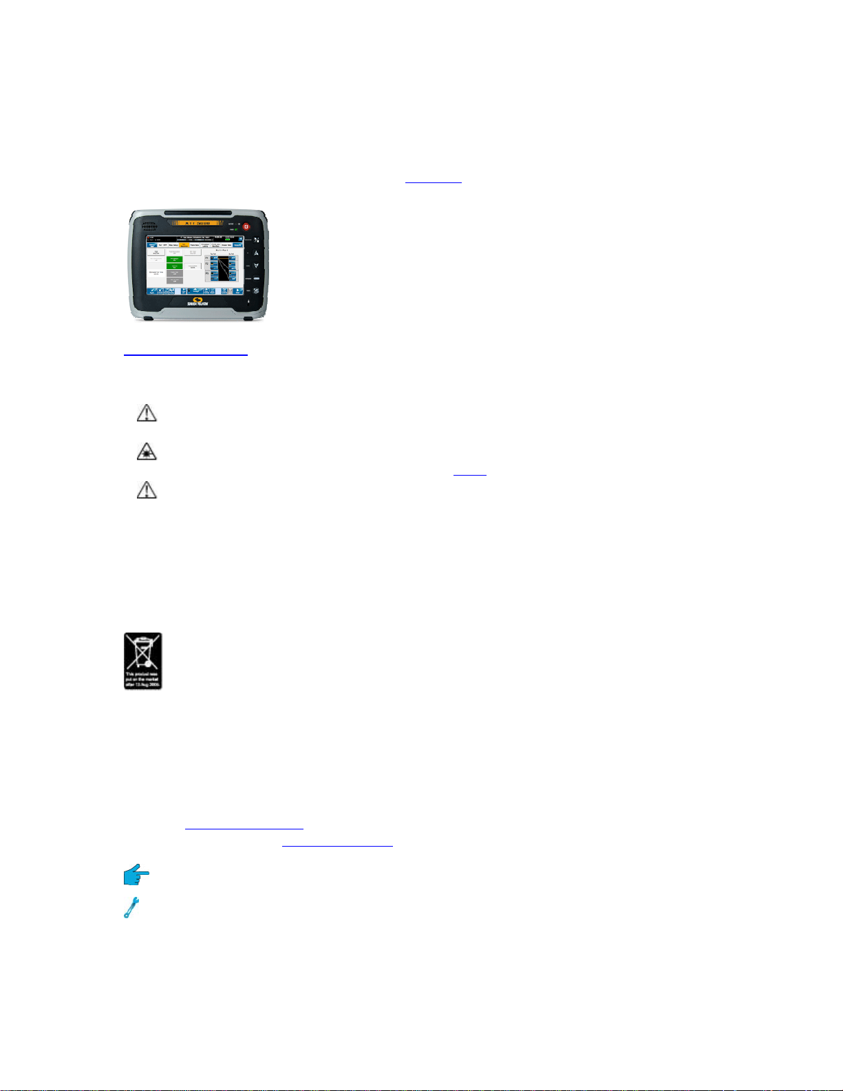
XTT 5000 System
Important Information Home
XTT 5000 provides not only sophisticated technical
specifications, but easy to use applications for the
verification, turn-up, and hand-off of Ethernet services.
Use XTT 5000 in conjunction with another test set or
loopback device (such as the Metro Responder), to
qualify network performance and verify quality of
service per ITU and MEF standards and service level
agreements.
Unpacking Details
Warnings and Cautions
Using the supplied equipment in a manner not specified by Sunrise
End of Life Recycling and Disposal Information
Telecom may impair the protection provided by the equipment.
This is a Class 1 LASER product. Avoid looking directly at the Transmitter
source. For added safety, turn off the laser
Using the supplied equipment in a manner not specified by Sunrise
Telecom may impair the protection provided by the equipment.
when not in use.
DO NOT dispose of Waste Electrical and Electronic Equipment (WEEE) as unsorted
municipal waste. For proper disposal return the product to Sunrise Telecom. Please
contact our local offices or service centers for information on how to arrange the
return and recycling of any of our products.
EC Directive on Waste Electrical and Electronic Equipment (WEEE).
The Waste Electrical and Electronic Equipment Directive aims to minimize the
impact of the disposal of electrical and electronic equipment on the environment. It
encourages and sets criteria for the collection, treatment, recycling, recovery, and
disposal of waste electrical and electronic equipment.
Tips on XTT 5000 & this Help System
Disclaimer: Contents of this Help system are subject to change without notice and
are not guaranteed for accuracy.
Visit the Working Desktop
and features. Visit the Hardware Notes
Get a technology tip related to the topic.
Get a testing tip; information that will help you in your testing.
A button may be referred to via text, or via its icon.
FCC Information
page to get an overview of how to use XTT 5000's controls
for hardware tips.
1
Page 8

XTT 5000 User's Manual
FCC ID: UEBXT5000
This device complies with Part 15 of the FCC Rules. Operation is subject to the
following two conditions: (1) this device may not cause harmful interference, and (2)
this device must accept any interference received, including interference that may
cause undesired operation.
Note: This equipment has been tested and found to comply with the limits for a
Class A digital device, pursuant to Part 15 of the FCC Rules. These limits are
designed to provide reasonable protection against harmful interference when the
equipment is operated in a commercial environment. This equipment generates,
uses, and can radiate radio frequency energy and, if not installed and used in
accordance with the instruction manual, may cause harmful interference to radio
communications. Operation of this equipment in a residential area is likely to cause
harmful interference in which case the user will be required to correct the
interference at his own expense.
Any changes or modifications not expressly approved by the party responsible for
compliance could void the user’s authority to operate the equipment.
Caution: Exposure to Radio Frequency Radiation
To comply with FCC RF exposure compliance requirements, this device must not be
co-located or operating in conjunction with any other antenna or transmitter.
Where do you want to go next?
View a list of Help contents at Home.
Set up a Throughput test.
Set up an RFC2544 test
Set up an IP test
.
Set up a Monitor test
Configure a Loopback
Customer Service
Home
.
.
2
Page 9

Home
Use this page to move through the Help system quickly.
XTT 5000 System Information
XTT 5000 System
Important
Warnings and Recycling information; Unpacking.
Information
Working Desktop
Hardware Notes
Measurement
An overview of how the STT 5000 desktop works, including
the Menu
Information about chassis, ports and buttons. Get details
on Handling Optical Fiber
, LEDs and Windows desktop notes.
.
Setup a manual or timed test.
Setup
Network Setup
System Setup
Status
View or update the system.
Configure system Ethernet settings if necessary.
Date, Time Zone, Time (of day).
Customer Service Contact Sunrise Telecom; view warranty
Port Setup
Choose a Port
Port Address
RJ-45:
Set up test ports.
Configure test port addresses if necessary.
Negotiation On
RJ-45
Negotiation Off
SFP Port Setup
XFP Port Setup
information.
Throughput Testing
Throughput
Applications
Ethernet
Connection
Signal Setup
Select BERT or Live, and choose the test layer.
Stream Table
Setup
Summary
Results
Aggregate
Results
Stream Results
View statistics for one stream.
Non Test Stream
Results
RFC2544 Testing
RFC2544
Make sure the link is up; troubleshooting.
MAC
, VLAN, MPLS, IP, UDP, TCP, Payload, Traffic Shape, Rx
Filter
View overall results for all streams.
View counts for results for all test streams.
View statistics for traffic not conforming to the test.
3
Page 10

XTT 5000 User's Manual
Applications
RFC2544/NE
Test Setup
Test Sequence
Setup
Frame Sizes
Setup
Throughput and
Latency Setup
Frame Loss &
Back-to-Back
Setup
Stream Table
Setup
NE Stress Test
Setup
RFC2544
Summary
Results
RFC2544
Throughput
Latency Results
Throughput
Chart Results
Thruput
Aggregate
Results
Select to run an RFC2544 or NE Stress Test.
IP/Ping Testing
IP Testing
Application
IP Setup Tab
Ping Test Setup
Ping Test Results
Ping Echo Log
Choose PING or TRACEROUTE test, setup IP and VLAN
Get details on tx pings and rx ping echoes.
Ping Trace Route
Setup
Ping Trace Route
Results
Aggregate
Results
Loopback Features
Loopback Test Setup
Loopback Responder
Loop Control
Monitor Testing
details.
Applies to both PING and TRACEROUTE tests.
4
Page 11

Monitor Applications
Monitor Setup
Technology Overview
XTT 5000 System
Learn about Ethernet technology
.
5
Page 12
XTT 5000 User's Manual
Working Desktop Home
Important Information
Windows System
Notes
Hardware Notes
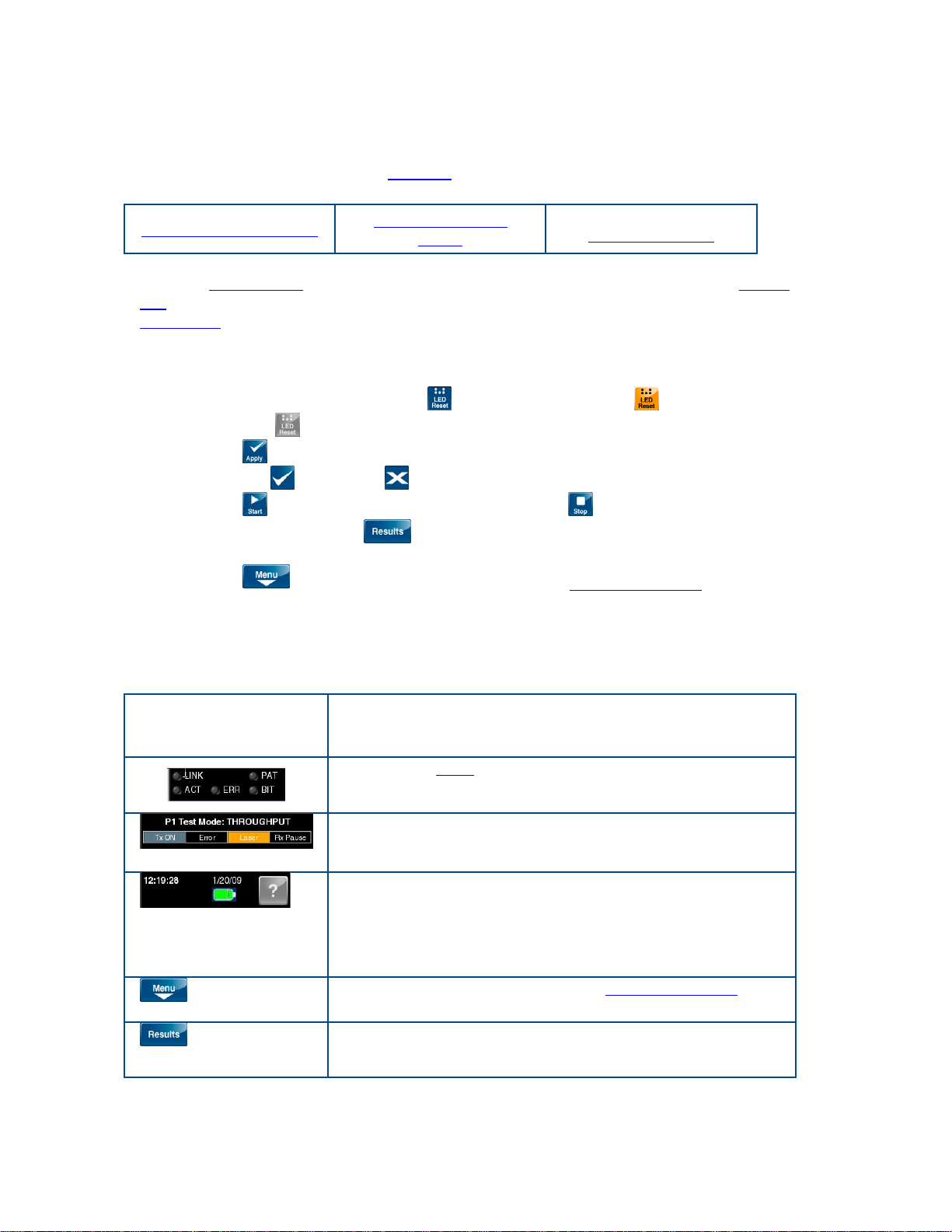
XTT 5000 is a touch-screen unit. Use your finger or the stylus to make selections.
Often, a number pad
will appear for use in entering alphanumeric data. The Status
Bar is the black row at the top of the screen; it provides system information. The
Action Bar
of buttons at the bottom of the screens gives access to many functions.
Here is an overview:
• Touch buttons to activate (single touch/click) the function, or to open (double
touch/click) their configuration screens.
• Button colors have meaning:
selection,
• Press
changes,
• Press
light gray-unavailable button.
to save changes and apply your new settings. When asked to verify
= Yes and = No (cancel).
to begin taking measurements. Press to stop a test.
• The 'Results' button (
blue-available button; orange-active
) at the top right takes you to the results screens,
but doesn't actually start a test.
• Press
to select a new test mode from the drop down menu. The
horizontal Menu Bar tabs will change depending on the test type (shown on
the Module Status panel; Throughput, RFC2554, etc.) selected. Touch a menu
tab label to see the items in that menu.
Status Bar: Located at the top of the screen.
Section Information
Soft virtual LEDs
the selected port.
show the logical and physical state of
Module Status Panel: Get module data, such as the
port, test mode and transmission status.
System Status Panel: Get system-related information,
including the battery charge status, and the '?' button,
Menu
Results
which is used to access this Help system. Press '?'
again to exi
t Help
Select a new test mode from the drop down menu
On the setup screens, press 'Results' to go to
measurement results.
.
6
Page 13
XTT 5000 System
Setup
Return to the test setup screen from a results window
(e.g Summary Results, Aggregate Results).
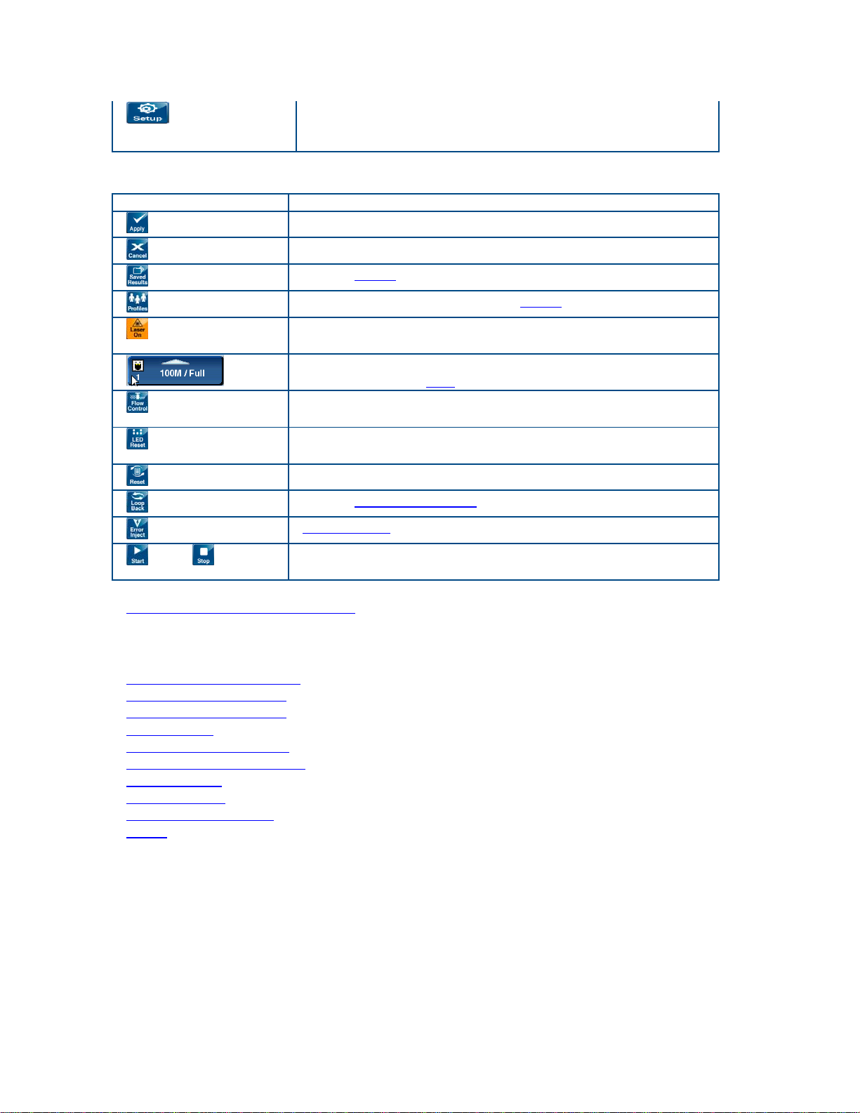
Action Bar: The Action Bar is located at the bottom of the screen.
Button Action
Apply
Cancel
Saved Results
Profiles
Laser On/Off
Save changes and apply your new settings.
Cancel (stop/delete) any changes in progress.
Access saved
Save or load test profiles. See saved
measurement results files.
files.
Activate the laser for testing. Turn the laser off for
safety.
View the type or port and its status. Press the button to
Port
Flow control
LED Reset
Reset
Loop Control
Error Inject
Start, Stop
select a different port
Transmits a flow control (pause) frame, according to
parameters set on the active port.
Clears all historical LED data, so the LEDs will display
the current line status.
Starts measurements counts over from 0.
Access Loopback Control
Inject errors
in the payload.
Start and stop a test. To get measurement results, start
at test.
to use.
.
Generate a measurement report
.
Where do you want to go next?
Configure an RJ-45 port.
Configure an SFP port.
Configure an XFP port.
Meas. Setup
: Configure measurement parameters
Throughput Test Setup
RFC2544/NE Applications
IP Test Setup
Monitor Setup
Loopback Test Setup
Home
7
Page 14

XTT 5000 User's Manual
Unpacking Home
To unpack and test a new test set:
1. Remove the packing list, test set, and accessories from the shipping
container.
2. Inspect all parts and immediately report any damage to the carrier and to
Sunrise Telecom.
3. Verify that all parts specified on the packing list were received.
4. Complete the Warranty Registration Card and return it immediately to Sunrise
Telecom.
Note: Sunrise Telecom must receive the Warranty Registration Card in order
to provide software updates.
Where do you want to go next?
Configure an RJ-45 port.
Configure an SFP port.
Meas. Setup
Throughput Test Setup
RFC2544/NE Applications
IP Test Setup
Monitor Setup
Loopback Test Setup
Working Desktop
Home
: Configure measurement parameters
8
Page 15

XTT 5000 System
Windows System Notes Home
Press the bottom hardware button to move between the XTT 500 and the Windows
system desktop. On the Windows desktop, access useful basic computer tools:
System
• Reset system: Shut down and restart.
• Calibrate Touchscreen: Recalibrate the touch screen if screen response
seems off. Touch each 'x'.
• XTT 5000: Start the XTT 5000 application.
PDF Viewer: Launch a viewer to read PDF files.
Calculator
File Manager
System Administrator: Access XTT 5000 system information and setups.
Eject SD Card: Safely eject an SD memory card.
Eject USB Drive: Safely eject a USB memory drive.
Important Note - Caution: External memory devices must be ejected properly,
using the appropriate button, in order to safeguard your data. Failure to eject a drive
properly may result in lost data.
Where do you want to go next?
The Working Desktop
Configure an RJ-45 port.
Configure an SFP port.
Configure an XFP port
Meas. Setup
Throughput Test Setup
RFC2544/NE Applications
IP Test Setup
Monitor Setup
Loopback Test Setup
Home
: Configure measurement parameters
.
9
Page 16

XTT 5000 User's Manual
Hardware Notes Home
XTT 5000 is a touch screen test set; use your finger or a stylus to make selections.
However, you may find attaching and using a mouse is fastest. Plug the power cord
in on the right side, and press and hold the top round button for a few moments to
turn the unit on (or off).
Get unpacking details
Ports - Right Side
SD Card Use to transfer files; may also use Micro SD with SD
10/100 Ethernet Use for a network connection.
Mini USB client Used to send files between a computer and the XTT 5000
Power Plug in the AC charger.
Ports - Left Side
2 USB host ports: Use to attach USB devices, e.g., keyboard and mouse.
.
Adapter.
hardware.
USB Mouse Troubleshooting Hint: For best functionality, use a ferrite mouse, or
place a ferrite bead on the USB mouse cord.
Ports - Top
The top connector panel holds the test ports; a combination of RJ-45, SFP, and XFP
ports, depending on the configuration ordered.
• See Port_Address
• See Choose a Port
• See SFPs and XFPs are hot-swappable. Handle the bale carefully, and avoid
touching the end of the connector. See Handling Optical Fiber
Buttons
• The round top button is the power on/off button.
• The top square button brings up the soft keyboard. Press it again to bring up
a number pad.
• Use the Up (third button) and Down (fourth) buttons on the right side of the
chassis to scroll up and down in the screens.
A scroll bar appears on a screen where there is more information below the
current window (for example, results and Help screens often have long
pages).
• Use the bottom button to toggle between the computer desktop
5000 application.
External Storage
.
.
.
and the STT
If you are using an external form of storage on the XTT-5000 (USB drive, etc.) (and
have written files to the external volume), you must cleanly dismount the volume
from Windows
external storage volume.
Use a desktop icon
10
before removing it, or the files may not be written safely to the
to Safely Remove Hardware.
Page 17

Where do you want to go next?
Unpacking Details
Configure an RJ-45 port.
Configure an SFP port.
Meas. Setup
Throughput Test Setup
RFC2544/NE Applications
IP Test Setup
Monitor Setup
Loopback Test Setup
Working Desktop
Home
: Configure measurement parameters
XTT 5000 System
11
Page 18
XTT 5000 User's Manual
Handling Optical Fiber Home
In general, handle fiber patch cords and connectors carefully. Always replace dust
covers. Keep the optical connectors clean, and make a practice of not looking into
fiber ends.
An optical fiber is a strand of glass about the same diameter as a human hair.
Though it is remarkably durable, careful handling is required to ensure continued
high performance and long life.
• Do not pull or kink patch cords, as the glass strand in the middle might
become damaged or broken.
• A sharp bend will cause excessive signal loss.
• Keep patch cord bend radiuses no less than an inch.
• Use specialized optical cable raceways and plenums whenever they are
available.
• Don’t use tie wraps as you would with electrical cables. Tie wraps will put
strain on the fiber. The next figure shows the proper method of wrapping and
securing fiber patch cords.
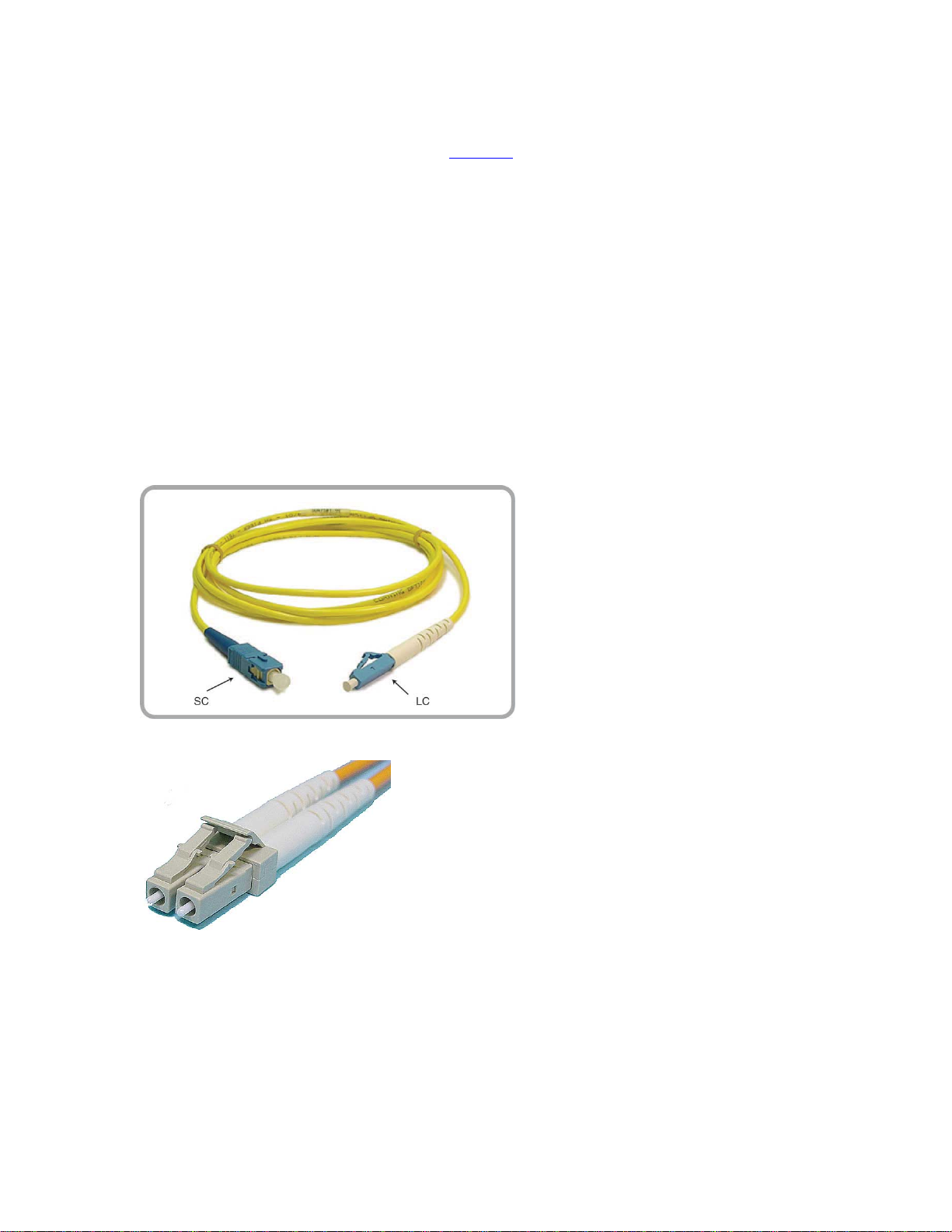
There are several types of
optical connectors in use today.
This figure shows the two most
popular for Ethernet, SC and
LC.
SC to LC Cable
This is a duplex multi-mode LC cord.
Look closely at the pictures to see the
details of the connection mechanism.
Duplex LC Cable
• When using optical connectors, insert or remove the ferrule straight into the
sleeve.
• Minimize wiggling the connector as this may loosen the tight fit that is
required for the ferrule and sleeve.
• For SC connectors, orient the prominent key on the connector body with the
slot in bulkhead adapter. Push the connector in until it clicks. To remove,
12
Page 19

XTT 5000 System
pinch the connector body between your thumb and finger, and gently pull
straight out.
• LC connectors evolved from the basic RJ-45 connector design, and are placed
on and removed in the same fashion as an RJ-45. Simply push the rear
prongs together to release the connector. Listen for the click when you seat
the connector.
Cleaning Optical Fiber
Fiber optic connectors must be kept clean to ensure long life of the connectors and to
minimize transmission loss at the connection point.
Precautions
• When not in use, always replace dust covers and caps to prevent deposits and
films from airborne particles. A single dust particle caught between two
connectors will cause significant signal loss. Dust particles can scratch the
polished fiber end, resulting in permanent damage.
• Do not touch the connector end or the ferrules, since this will leave an oily
deposit from your fingers.
• Do not allow uncapped connectors to drop on the floor.
How to Clean
• Should a fiber connector become dirty or exhibit high loss, carefully clean the
entire ferrule and end face.
• Special lint-free pads should be used with isopropyl alcohol.
• Even though not very accessible, the end face in a bulkhead adapter on test
equipment can be cleaned by using a special lint-free swab, again with
isopropyl alcohol.
• In extreme cases, a test unit may require more thorough cleaning at the
factory.
• Cotton, paper, or solvents should never be used for cleaning since they may
leave behind particles or residues.
• Use a fiber optic cleaning kit especially made for cleaning optical connectors,
and follow the directions.
• Canned air can do more harm than good if not used properly. Again, follow
the directions that come with the kit.
Where do you want to go next?
• Throughput Test Setup
• RFC2544/NE Applications
• IP Test Setup
• Monitor Setup
• Loopback Test Setup
• Working Desktop
• Home
13
Page 20

XTT 5000 User's Manual
Customer Service
Sunrise Telecom Customer Service is available 24/7. Customer Service performs the
following functions:
• Answers customer questions over the phone on such topics as product
operation and repair.
• Repairs malfunctioning XTT promptly.
• Provides information about product upgrades.
The warranty
hardware, software, accessories, and the battery.
A Return Merchandise Authorization (RMA) Number is required before any product
may be shipped to Sunrise Telecom for repair. Out-of-warranty repairs require both
an RMA and a Purchase Order before the unit is returned. All repairs are warranted
for 90 days.
Please contact Customer Service if you need additional assistance:
period covering the XTT 5000 is one year from the date of shipment on
Customer Service
Sunrise Telecom Incorporated
302 Enzo Drive
San Jose, CA 95138 U.S.A.
Tel: 1 408 363 8000 or 1 800 701 5208 (24 hours)
Fax: 1 408 363 8313
Internet: http://www.sunrisetelecom.com
E-mail: [email protected]
Offices
Sunrise Telecom offices are located around the world:
HEADQUARTERS
302 Enzo Drive, San Jose, CA 95138, USA
Tel: 408-363-8000, Fax: 408-363-8313
BROADBAND PRODUCTS GROUP - ATLANTA
3075 Northwoods Circle, Norcross, GA 30071, USA
Tel: 770-446-6086, Fax: 770-446-6850
[email protected]
OPTICAL PRODUCTS GROUP
7b Route Suisse, 1295 Mies, Switzerland
Tel: +41-22-755-5650, Fax: +41-22-755-5667
PROTOCOL PRODUCTS GROUP
Via Jacopo Peri, 41/c, 41100 Modena, ITALY
Tel: +39-059-403711, Fax: +39-059-403715
SUNRISE TELECOM CHINA
Room 1503, Tower 3 , No.1, Xizhimenwai Street
Xicheng District, Beijing, 100044, CHINA
Tel: +86-10-5830-2220, Fax: +86-10-5830-2239
14
Page 21

SUNRISE TELECOM FRANCE SAS
ZA Courtaboeuf 2 - Immeuble le Ceylan
6 Allée de Londres 91140 Villejust, FRANCE
Tel: +33 (0) 1 6993 8990, Fax: +33 (0) 1 6993 8991
SUNRISE TELECOM GERMANY GmbH
Buchenstr. 10
D- 72810 Gomaringen, GERMANY
Tel: +49 (0) 7072 9289 58, Fax: +49 (0) 7072 9289 55
SUNRISE TELECOM ITALY
Via G. Matteotti 98, Cinisello Balsamo (MI) 20092, ITALY
Tel: +39-023-651-1327, Fax: +39-029-287-8764
SUNRISE TELECOM JAPAN
Aoyamakouei Bldg 2F, 2-7-24, Kita-Aoyama,
Minato-Ku, Tokyo 107-0061 JAPAN
Tel: +81-3-5772-3403, Fax: +81-3-5770-4037
SUNRISE TELECOM LATIN AMERICA
Calle Cerro de las Campanas #3, Of. 418
Col. San Andrés Atenco, 54040 Tlalnepantla, México, MEXICO
Tel: +52-55-5370-2124
SUNRISE TELECOM TAIWAN
21, Wu Chuan 3rd Road, Wu-Ku Hsiang
Taipei County, 248, Taiwan, R.O.C.
Tel: +886-2-2298-2598, Fax: +886-2-2298-2575
XTT 5000 System
Where do you want to go next?
Throughput Test Setup
RFC2544/NE Applications
IP Test Setup
Monitor Setup
Loopback Test Setup
Working Desktop
Home
15
Page 22

XTT 5000 User's Manual
Express Limited Warranty Home
A. Hardware Coverage. COMPANY warrants hardware products against defects in
materials and workmanship. During the warranty period COMPANY will, at its sole
option, either (i) refund of CUSTOMER’S purchase price without interest, (ii) repair
said products, or (iii) replace hardware products which prove to be defective;
provided, however, that such products which COMPANY elects to replace must be
returned to COMPANY by CUSTOMER, along with acceptable evidence of purchase,
within twenty (20) days of request by COMPANY, freight prepaid.
B. Software and Firmware Coverage
firmware materials against defects in materials and workmanship. During the
warranty period COMPANY will, at its sole option, either (i) refund of CUSTOMER’S
purchase price without interest, (ii) repair said products, or (iii) replace software or
firmware products which prove to be defective; provided, however, that such
products which COMPANY elects to replace must be returned to COMPANY
by CUSTOMER, along with acceptable evidence of purchase, within twenty (20) days
of request by COMPANY, freight prepaid. In addition, during the warranty period,
COMPANY will provide, without charge to CUSTOMER, all fixes, patches, new releases
and updates which COMPANY issues during the warranty period. COMPANY does not
warrant or represent that all software defects will be corrected. In any case where
COMPANY has licensed a software product “AS IS,” COMPANY’S obligation will be
limited to replacing an inaccurate copy of the original material.
C. Period
Year from date of shipment to CUSTOMER. The COMPANY may also sell warranty
extensions or provide a warranty term of three years with the original sale, which
provide a longer coverage period for the test set chassis, software and firmware, in
which case the terms of the express limited warranty will apply to said specified
warranty term.
D. Only for CUSTOMER
CUSTOMER and not for the benefit of any subsequent purchaser or licensee of any
merchandise.
E. LIMITATION ON WARRANTY
WARRANTY MADE BY COMPANY WITH RESPECT TO HARDWARE, SOFTWARE AND
FIRMWARE. THERE ARE NO OTHER WARRANTIES, EXPRESS OR IMPLIED. COMPANY
SPECIFICALLY DISCLAIMS THE IMPLIED WARRANTIES OF MERCHANTABILITY AND
FITNESS FOR A PARTICULAR PURPOSE. COMPANY’S LIABILITY UNDER THIS
AGREEMENT WITH RESPECT TO A PRODUCT, INCLUDING COMPANY’S LIABILITY FOR
FAILURE AFTER REPEATED EFFORTS TO INSTALL EQUIPMENT IN GOOD WORKING
ORDER OR TO REPAIR OR REPLACE EQUIPMENT, SHALL IN NO EVENT EXCEED THE
PURCHASE PRICE OR LICENSE FEE FOR THAT PRODUCT, NOR SHALL COMPANY IN
ANY EVENT BE LIABLE FOR ANY INCIDENTAL, CONSEQUENTIAL, INDIRECT, OR
SPECIAL DAMAGES OF ANY KIND OR NATURE WHATSOEVER, ARISING FROM OR
RELATED TO THE SALE OF THE MERCHANDISE HEREUNDER, INCLUDING BUT NOT
LIMITED TO DAMAGES ARISING FROM OR RELATED TO LOSS OF BUSINESS, LOSS
OF PROFIT, LOSS OF GOODWILL, INJURY TO REPUTATION, OVERHEAD, DOWNTIME,
REPAIR OR REPLACEMENT, OR CHARGE-BACKS OR OTHER DEBITS FROM CUSTOMER
OR ANY CUSTOMER OF CUSTOMER.
F. No Guaranty, Nonapplication of Warranty
that the operation of hardware, software, or firmware will be uninterrupted or errorfree. Further, the warranty shall not apply to defects resulting from:
(1) Improper or inadequate maintenance by CUSTOMER;
. The warranty period for Hardware, Software and Firmware will be One (1)
. COMPANY makes this warranty only for the benefit of
. COMPANY warrants software media and
. THIS CONSTITUTES THE SOLE AND EXCLUSIVE
. COMPANY does not guaranty or warrant
16
Page 23

XTT 5000 System
(2) CUSTOMER-supplied software or interfacing;
(3) Unauthorized modification or misuse;
(4) Operation outside of the environmental specifications for the product;
(5) Improper site preparation or maintenance; or
(6) Improper installation by CUSTOMER.
Where do you want to go next?
Throughput Test Setup
RFC2544/NE Applications
IP Test Setup
Monitor Setup
Loopback Test Setup
Working Desktop
Home
17
Page 24

XTT 5000 User's Manual
Menu Home
Press 'Menu' on the working desktop to choose the type of test to perform. The menu
selections appear below the button.
Parameter Details
SYSTEM Configure basic system properties if necessary.
THROUGHPUT Perform a BER test; perform end-to-end testing with a test
pattern; get results on the pattern. This is the basic
configuration.
RFC2544/NE
TEST
IP TEST Perform an IP /Ping Test to check Layer 3 connectivity.
LOOPBACK Loop incoming traffic back to its source.
MONITOR Bidirectionally monitor live traffic.
Take measurements in accordance with RFC 2544.
The secondary port may be in Loopback mode regardless of
the test performed by the primary port.
Where do you want to go next?
The Working Desktop
BERT Application - Layer 1
BERT Application - Layer 2
RFC2544 Applications
IP Test Setup
Loopback Test Setup
Loop Control
Monitor Applications
Home
18
Page 25
XTT 5000 System
LEDs Home
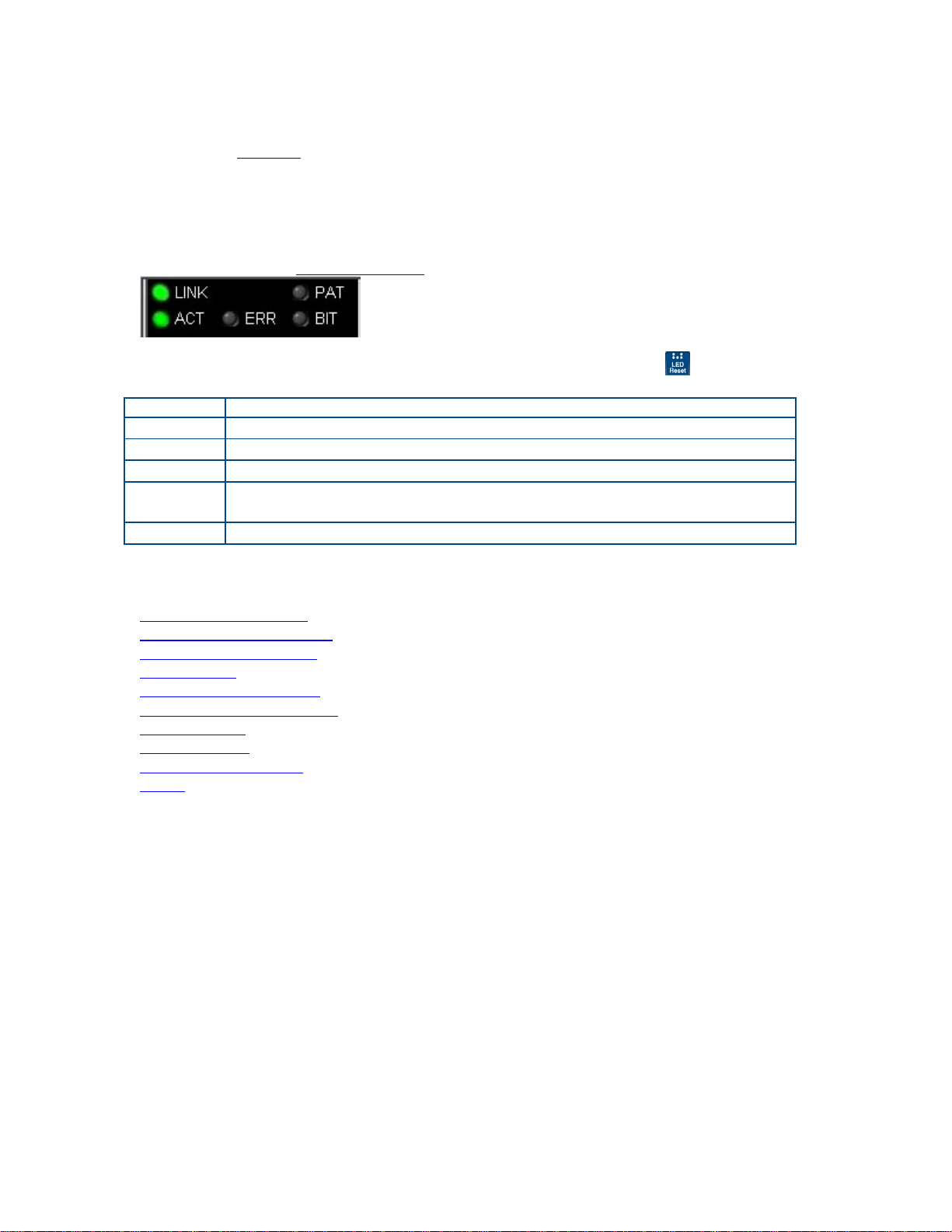
Physical LEDs are located next to the ports on the top of XTT 5000. They report on
the status of the Ethernet connection.
Green = good
Red = bad
Virtual LEDs on the working desktop
Green = good
Red = bad
- steady red: currently receiving errors/alarms
- flashing red: errors/alarms received in the past.
provide line status.
Press 'LED Reset' (
flashing.
LED Details
Link Connected/not connected Ethernet link status.
ACT Activity status of the Ethernet link.
ERR Received errors.
PAT Test pattern errors; received pattern does not match the expected
pattern.
BIT Bit errors received.
) to clear the
Where do you want to go next?
The Working Desktop
Configure an RJ-45 port.
Configure an SFP port.
Meas. Setup
Throughput Test Setup
RFC2544/NE Applications
IP Test Setup
Monitor Setup
Loopback Test Setup
Home
: Configure measurement parameters
19
Page 26

XTT 5000 User's Manual
Measurement Setup Home
Configure how and when results are taken.
Parameter Options Details
Start Mode PROGRAM: Program a specified
date and time in the future to
begin taking measurements. Once
you have selected Program, enter
the desired date and time in the
next two items.
MANUAL: Manually begin the test
measurements.
Stop Mode CONTINUOUS: Test will run
indefinitely until you press 'Stop'.
TIMED: Test runs for the Test
Duration length of time.
Start Time Specify the Hour, Minute, and
Seconds to begin measurements.
Test
Hours/Minutes
Start Date Enter the Year, Month, and Day to
Save Mode Auto_Save: Results are saved
Start TX
Coupled
To access the window, touch Measurement Setup on the System Setup
Enter the number of Hours and
Minutes you want the test to run
for in those fields.
begin measurements.
automatically when the test is
stopped. A file name will be
assigned automatically.
Never_Save: Results are not
saved.
Manual_Save: Results are saved
when the test is stopped. A dialog
box will appear for you to input a
filename in.
On: The transmitter and
measurement begin at the same
time.
Off: A 'TX On' button appears on
the Action Bar. This button is
grayed out until the measurement
is started. Once the measurement
is started, press the 'TX On' button
to begin sending traffic.
Select the method to
begin your test
measurements.
Set the mode in which
measurements will be
taken.
Start Mode=PROGRAM.
Stop Mode=TIMED.
Set the length of time
a timed test will run
once you press 'Start'.
Start Mode=PROGRAM.
On the calendar which
appears, use the
arrows to scroll to the
month you want, then
tap the specific date.
Select the method to
save your test
measurements.
Determine when the
transmitter will turn
on.
menu.
20
Page 27

Where do you want to go next?
Throughput Stream Table Setup
Throughput Summary Results
Throughput Aggregate Results
Tech: Ethernet Overview
Home
XTT 5000 System
21
Page 28

XTT 5000 User's Manual
Status Home
Get details on XTT 5000 system performance. Select Menu > System > Status.
General
Statistic Meaning
File Usage Percentage of system currently in use.
Memory
Usage
Temperature Unit temperature; normal range is 0˚C to 45˚C.
Power
Statistic Meaning
AC Power ON if the unit is plugged in; OFF if it is not.
Total Charge The percentage of charge remaining in the battery; see the
Remaining
Time
Time to Full
Charge
Percentage of system RAM in use.
Battery icon
When running on battery, approximately how long the battery
will last.
When running on battery, approximately how long it will take to
recharge the battery.
.
Version Information
Firmware Version
Serial Number
Where would you like to go next?
Test Type Menu
Working Desktop Overview
Home
22
Page 29

XTT 5000 System
System Setup Home
Set the basic system information if required. Select Menu > System > System Setup.
System Clock
Parameter Function
Date Set the calendar date if necessary.
Time Enter the time of day on the pop window.
Get Local Time Align the XTT-5000 system clock to the time that
is "local" to the PC with the browser.
Applies when XTT-5000 is controlled from a
"remote browser".
Where do you want to go next?
Throughput Signal Setup
Throughput Stream Table Setup
Throughput Summary Results
Tech: Ethernet Overview
Loopback Test Setup
IP Test Setup
IP Testing
Throughput Test Setup
RFC2544 Applications
Home
23
Page 30
XTT 5000 User's Manual
Date Home
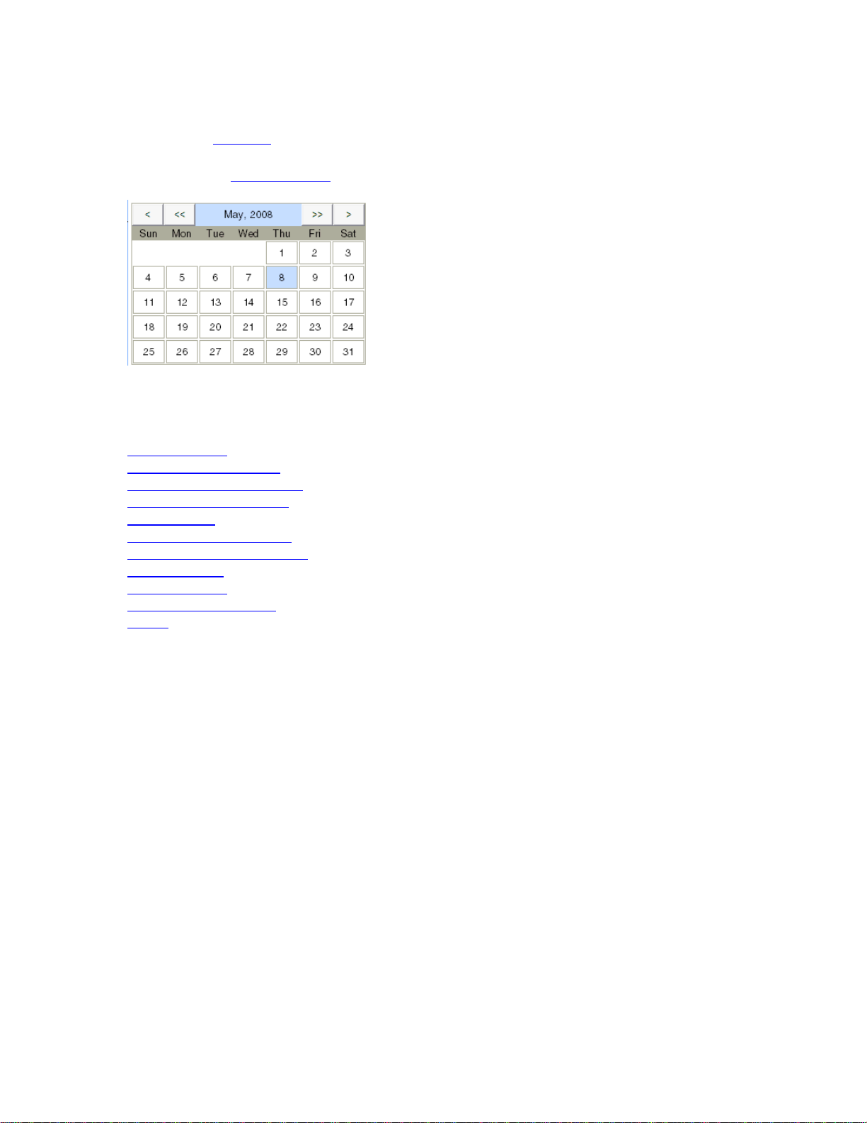
Press Date on System Setup tab to set the calendar date for the system. The
calendar window is shown below.
To select a date, click on it.
<< , >> Move backward or forward a year.
< , > Move backward or forward a month.
Set the Calendar Date
Where do you want to go next?
System Setup
The Working Desktop
Configure an RJ-45 port.
Configure an SFP port.
Meas. Setup
Throughput Test Setup
RFC2544/NE Applications
IP Test Setup
Monitor Setup
Loopback Test Setup
Home
: Configure measurement parameters
24
Page 31

XTT 5000 System
Time Zone Home
Press Time Zone on the System Setup tab to select the local time zone.
Press the button corresponding to your time zone.
The window will close and return you to the System Setup
Where do you want to go next?
System Setup
The Working Desktop
Home
Configure an RJ-45 port.
Configure an SFP port.
Meas. Setup
Throughput Test Setup
RFC2544/NE Applications
IP Test Setup
Monitor Setup
Loopback Test Setup
: Configure measurement parameters
window.
25
Page 32

XTT 5000 User's Manual
Time Home
Set the time of day. Press Time on the System Setup tab to access this function.
The cursor appears to the left of the time on the window.
Enter the entire time of day, in the hours:minutes:seconds format.
Enter the time using the number pad
Select AM or PM at the bottom of the number pad.
Where do you want to go next?
The Working Desktop
System Setup
Configure an RJ-45 port.
Configure an SFP port.
Meas. Setup
Throughput Test Setup
RFC2544/NE Applications
IP Test Setup
Monitor Setup
Loopback Test Setup
Home
: Configure measurement parameters
.
26
Page 33

XTT 5000 System
Network Setup Home
Configure system settings if necessary. Access this window from the System menu
Network Setup tab.
Ethernet Port
Configure the system settings, if necessary.
IMPORTANT NOTE: These settings apply to the XTT 5000 module’s own LAN
port, NOT the test ports. Changing these settings may cause the module to lose
connection with the system.
Parameter Details
Admin IP Enter the IP address for the XTT 5000 module.
Subnet Mask Enter the subnet address for the XTT 5000 module, if
appropriate.
Gateway Specify the gateway address for the XTT 5000. Used for
static IP.
DHCP Enabled XTT 5000 automatically retrieves the appropriate IP
address when connected to a LAN. When enabled, the
previous three items are grayed out.
MAC Address View the LAN port's MAC address.
DNS servers
Parameter Details
Primary DNS
Server
Secondary DNS
Server
Specify the local primary (master) DNS server address.
Enter an address directly, using the number pad which pops
up.
The secondary Server is a server that obtains information
about a zone from a Primary Server via a zone transfer
mechanism. Sometimes known as a Slave Server.
Specify the secondary (slave) DNS server address.
Where do you want to go next?
Configure an RJ-45 port.
Configure an SFP port.
Meas. Setup
Throughput Test Setup
RFC2544/NE Applications
IP Test Setup
Monitor Setup
Loopback Test Setup
Home
: Configure measurement parameters
27
Page 34

XTT 5000 User's Manual
System Update Home
View the system's current version as well as a list of other available versions, and
install updates.
XTT 5000 will check for a software update when you enter the screen; this takes
several seconds.
The 'Install Update' button becomes available if a new update is found. Press it to
install the update. XTT 5000 will look for upgrade files in the following locations, in
order:
USB Drive
SD Card
Network Server
Often, XTT 5000 will power off to complete the update. Power the unit back on to
resume testing.
Press 'Refresh' to recheck the current software version.
Where would you like to go next?
Menu
Working Desktop Overview
Home
28
Page 35

XTT 5000 System
Port Address Home
Configure the local port settings, if necessary.
IMPORTANT NOTE: These settings apply to the XTT 5000 module’s test ports.
For each port, set the IP Address, Subnet Mask, and Gateway addresses, and view
the factory default MAC Source address. The port numbers refer to the port labels on
the outside of the unit.
A number pad will appear for you to edit the addresses with.
Make sure to press 'Laser On' in the Action Bar
Where would you like to go next?
Port Summary
RJ45 Port: Auto-Neg On
SFP Port Configuration
XFP Port Setup
Menu
Working Desktop Overview
Home
to activate the laser when required.
29
Page 36

Page 37

Port Setup
Choose a Port Home
The port selection button at the bottom center of the screen
reports the connection type (shown by the connector; RJ-45
here) and rate (100M/Full duplex here).
Press the button to change the port in use. The Ports Summary window appears.
The port in use is highlighted. Port and test data appears for each port.
To select another port, touch its icon.
Configure an RJ-45, Auto Negotiation On
Configure a 1 GigE SFP
Configure a 10 GigE XFP
Configure a Port Address
Choose a port to test with
Tests can run on all three ports at the same time.
Port1: XFP – 10 GigE test
Port2/3: RJ-45 – 10/100/1000BASE-T test
Port2/3: SFP – 1000BASE-T or 100BASE-FX test
Possible Port Combinations
A Port1: XFP Port2: RJ-45 Port3: RJ-45
B Port1: XFP Port2: RJ-45 Port3: SFP
C Port1: XFP Port2: SFP Port3: SFP
D Port1: XFP Port2: SFP Port3: RJ-45
• Port2/3 can't be selected as RJ-45 and SFP at the same time; only one
interface at a time.
port.
port.
if necessary.
, Auto Negotiation Off
Where do you want to go next?
The Working Desktop
Configure an RJ-45 port.
Configure an SFP port.
Configure an XFP port
Meas. Setup
Throughput Test Setup
RFC2544/NE Applications
IP Test Setup
Monitor Setup
Loopback Test Setup
Home
: Configure measurement parameters
.
31
Page 38

XTT 5000 User's Manual
RJ-45 Port Setup: Auto-Negotiation On Home
Select a test from the menu in order to access the port configuration tabs.
Green buttons: On/active
Gray buttons: Off/inactive
Auto Negotiation: The unit will auto-negotiate with the link partner, selecting the
highest mutually compatible rate between the two ports.
• The port settings (including line rate, duplex, pause, etc) are negotiated
following the appropriate IEEE standards.
• See the negotiation results in the field.
Parameter Options Description
Advertisement 10M Half/Full
Duplex, 100M
Half/Full Duplex,
1000M Half/Full
Duplex
Pause On, Off Set if the local device will respond
RJ-45 Polarity Auto, Straight,
Cross
Pause Frame
0-335,539 μs Set the length of time indicated
Delay
Asymmetric
Pause
Decide if the TX port will send
The unit can ’advertise’ itself as
running at the rate(s) you select
by pressing the rate buttons.
to pause packets.
Determine the wiring polarity of
the Ethernet Port.
by the Pause frame sent by the
module.
Pause frames even if the receiver
has disabled.
RJ-45 Port Window
Auto-Negotiations Result field: Presents the auto-negotiations results. The field
appears on the right side of the window.
Where do you want to go next?
RJ45 Port Setup: Auto-Neg Off
Throughput Applications
RFC2544 Applications
Home
32
Page 39

Port Setup
RJ-45 Port Setup: Auto-Negotiation Off Home
Select a test from the menu in order to access the port configuration tabs.
Auto Negotiation: The unit will auto-negotiate with the link partner, selecting the
highest mutually compatible rate between the two ports.
• The port settings (including line rate, duplex, pause, etc) are negotiated
following the appropriate IEEE standards.
• If you set Auto Negotiation to on
itself.
When Auto Negotiation is set to Off, configure the following:
Parameter Options Description
Port Rate 10M, 100M, 1000M Set the line rate
Port Duplex Full Duplex, Half
Duplex
Pause On, Off Set if the local device will respond
RJ-45
Polarity
Pause
AUTO, Straight,
Cross
0-335,539 Set the length of time indicated by
Frame
Delay
, you can set how the XTT 5000 advertises
Configure the Ethernet mode.
to pause packets.
Determine the wiring polarity of
the Ethernet Port.
the Pause frame sent by the
module.
Where do you want to go next?
Throughput Test Setup
RFC2544 Applications
Home
33
Page 40

XTT 5000 User's Manual
Pause Frame Delay Home
Parameter Options Details
Pause Frame
Delay
On the RJ45 port setup window (Auto-Negotiation off)
(μs)' button to access this setting. A number pad appears for you to enter the
number with.
0 to 3355
μs
Set the length of time indicated by the
Pause frame sent by the XTT 5000.
, touch the 'Pause Frame Delay
Press
to ok your choice.
Where do you want to go next?
Configure an RJ-45 port
Configure an SFP port
Throughput Test Setup
RFC2544 Test Summary
Home
34
Page 41

Port Pause Home
Parameter Options Details
Port
Pause
XTT 5000 will only send pause frames when you choose, and it will send them
when instructed to do so, even if the RX Pause is off.
Where do you want to go next?
Throughput Test Setup
RFC2544 Test Summary
Home
Off: The test port will
temporarily stop
transmitting upon reception
of pause flow control
frames.
On: The test port will not
stop upon reception of flow
control frames.
Set how the local device will
respond to pause packets.
Port Setup
35
Page 42

XTT 5000 User's Manual
Port Duplex Home
Parameter Options Details
Port
Duplex
Where do you want to go next?
Throughput Test Setup
RFC2544 Applications
Home
Half: The local device will attempt to
link up in half-duplex mode. Data
cannot be transmitted and received at
the same time.
Full: The local device will attempt to
link up in full-duplex mode. The data
can be transmitted and received at the
same time.
Configure the
Ethernet mode.
36
Page 43

Port Setup
Asymmetric Pause Home
On The TX port sends Pause frames even if the receiver has
disabled Pause.
Off The TX port does not sends Pause frames.
The Asymmetric Pause settings only apply to Auto-Negotiation.
You may always transmit pause frames regardless of this setting.
Upon completion of the auto-negotiation information exchange, the arbitration
process determines the highest common mode and enables the appropriate
functions.
Where do you want to go next?
Throughput Test Setup
RFC2544 Test Summary
Home
37
Page 44

XTT 5000 User's Manual
RJ-45 Port Polarity Home
Determine the wiring polarity of the Ethernet Port.
• Match this setting to your cable type for specific testing purposes, or let the
unit accommodate whatever type of cable you use.
Options: Auto, Straight-through, Cross-over
Auto The unit automatically determines the
polarity of the cable connected to the
Ethernet port.
Straightthrough
Crossover
Where do you want to go next?
Throughput Test Setup
RFC2544 Test Summary
Home
Force the Ethernet port to work only with
a straight-through cable.
Force the Ethernet port to work only with
a cross-over cable.
38
Page 45
Port Setup
SFP Port Configuration Home
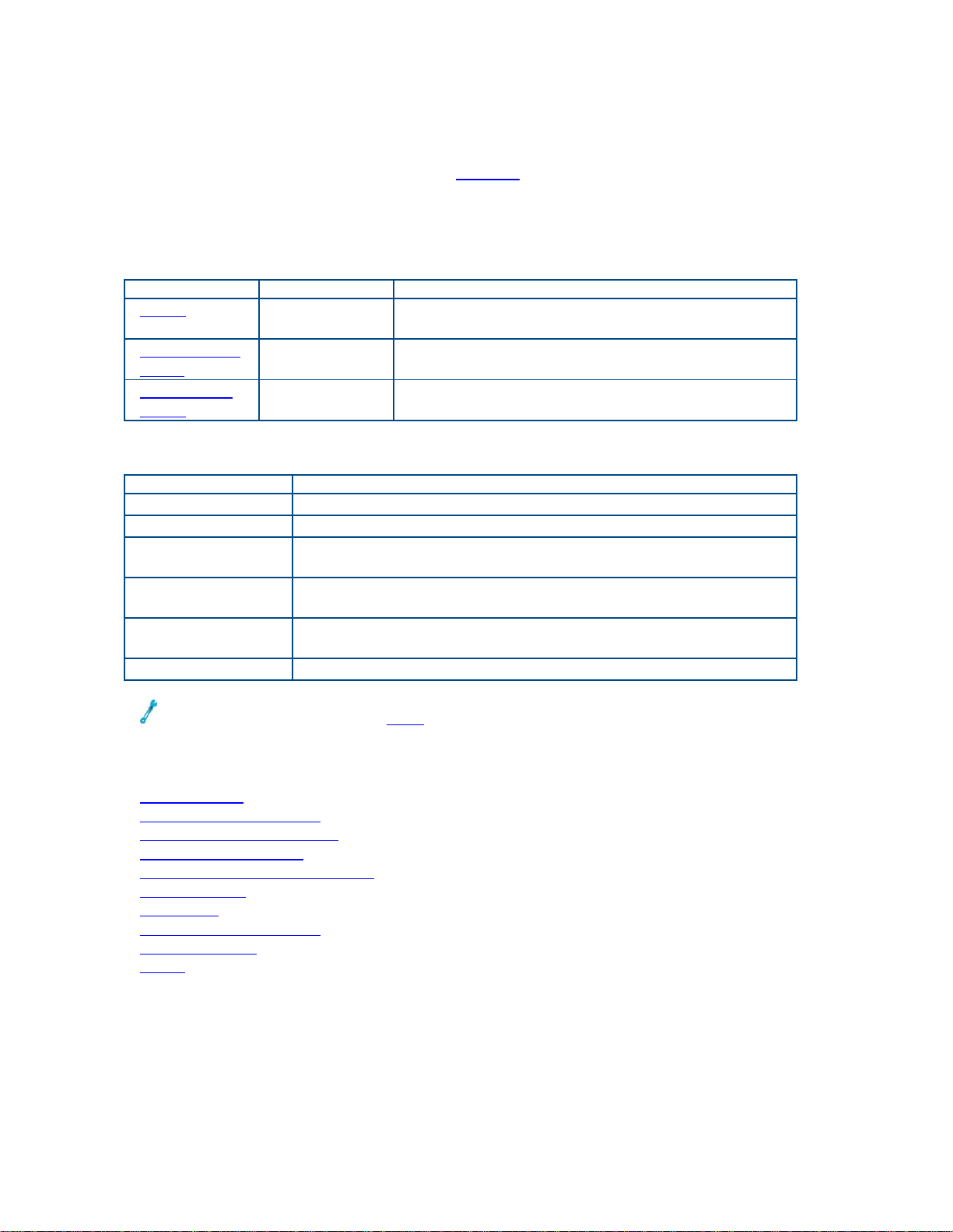
Interface: Set the Ethernet interface: Gigabit Ethernet, 100Base FX
Auto-Negotiation: Select ON to auto-negotiate with the link partner, selecting the
highest mutually compatible rate between the two ports.
Parameter Options Details
Pause On, Off Set to On, the unit will not stop transmitting
on receipt of flow control packets.
Pause Frame
Delay
Asymmetric
Pause
Auto-Negotiation Result
When Auto-Negotiation is On, view the results of the negotiations. Data includes:
Statistic Details
Line Rate
Duplex XTT 5000 duplex: Half or Full
Link Partner AN Whether the link partner uses Auto-Negotiation; shows as
Local RX, Tx
Pause
Remote RX, TX
Pause
Status Link status.
0 to 3355 μs Set the length of time indicated by the Pause
frame sent by the module.
On, Off Determine if the TX port will send Pause
frames even if the receiver has disabled Pause.
Disable or Enable.
Enable or Disable status of pause transmission by XTT
5000.
Enable or Disable status of link partner's transmission by
XTT 5000.
Remember to make sure the laser is on for testing.
Where do you want to go next?
Port_Address: Set the local port parameters.
Throughput Test Setup
RFC2544/NE Applications
Loopback Test Setup
Throughput Summary Results
IP Test Setup
IP Testing
Throughput Test Setup
IP Ping Testing
Home
39
Page 46

XTT 5000 User's Manual
XFP Port Setup Home
Touch the Port Button and choose the XFP 10 GigE port.
Select the XFP port for 10 Gigabit testing per applicable IEEE standards.
XTT 5000 supports the 10GE LAN-PHY. The XFP may be the primary or secondary
port.
Parameter Options Description
Pause On: The unit will not stop
transmitting on receipt of
flow control packets.
Off: Transmission stops.
Pause Frame
Delay
0 to 3355 μs Set the length of time indicated
Remember to make sure the laser is on for testing.
XTT 5000 support XFP digital diagnostics including:
• XFP Signal Results
• Vendor name
• Wavelength
• Rx optical power
Set the pause transmission
by the Pause frame sent by the
module
Where do you want to go next?
Throughput Test Setup
RFC2544/NE Applications
Loopback Test Setup
Throughput Summary Results
IP Test Setup
IP Testing
Throughput Test Setup
IP Ping Testing
Home
40
Page 47

Throughput Testing
Throughput Applications Home
Select Throughput as the test type on the menu. Before you begin testing, make
sure the link is up
To send loopback commands in a test, press the 'Loop Control
Action Bar
.
.
' ( ) button in the
BERT Applications
Select BERT as the Test Type on the Signal tab.
Layer 1 BERT
Layer 1 testing is used for verifying the quality of the physical layer connection. Most
commonly, this is done for basic point-to-point fiber connections, whether over a
single fiber pair or through a DWDM network.
Layer 2 BERT
Run a BERT between two testers.
Layer 2 testing is often performed to verify the quality of service provided over an
Ethernet network. Unlike a Layer 1 BERT , the Layer 2 BERT generates valid MAC
frames so that the test traffic can traverse through bridges and switches.
Caution: If you are sending packets to your responder via a router or other device
with its own IP address, make sure to set the Dest MAC to the MAC address of the
router, NOT the responder. Otherwise, the router will likely discard the packets
(without ARP in use).If you are staying down at layer 2 (MAC) this does not apply. IP
works fine if all the devices are on the same local network segment; this is applies
when sending traffic off your local network segment.
Where do you want to go next?
Throughput Summary Results
Throughput Aggregate Results
Throughput Stream Results
Throughput Test Setup
Working Desktop
Home
41
Page 48

XTT 5000 User's Manual
Ethernet Connection Home
Troubleshooting
Extras:
Before you begin testing, verify the link.
• Make sure to use the right type of connectors when connecting the test port
to the fiber access point of the network.
• Make sure the laser
• Verify the port has a green LINK LED
• For RJ-45 and SFP ports, if there is no link, then go to the Port window and
set the Auto-Negotiation to Disable (on both units, if applicable). If that
doesn’t work, set Auto-Negotiation to Enable, and configure the test set to
match the DUT settings.
Getting the link up is the most important step in any application, and it can be the
most frustrating. Take the time to ensure the Ethernet tab is properly configured.
You may need to make a change, see what effect that has, make another change,
and so on, until the configuration is correct.
Once you have a green LINK LED, testing is ready to begin.
Troubleshooting an ARP Error Message
The ARP feature makes configuring XTT 5000 easier. ARP takes an IP address and
returns the MAC address of the destination system.
If the unit Failed to resolve the host via ARP, one of two things are likely responsible:
• The IP Address configuration on the test equipment does not match the
network you are testing.
Solution: Enable DHCP if available, or check your network configuration by
pinging your default gateway. If you get no response, your configuration is
invalid.
• The IP Address provided for the destination host is wrong or the host is not on
the network.
Solution: Please check the configuration of the destination host.
From that host, attempt to ping the default gateway to verify network
connectivity.
• XTT-5000 will always ARP for the default gateway. If the ARP fails it will not
affect anything. Requesting the MAC of the default gateway is only required
when sending traffic off of your local Ethernet segment.
ARP Error Message STT Ethernet Connection
is turned on.
.
Troubleshooting an STT Ethernet Connection
If you are testing using an STT Ethernet there common configuration will cause
problems:
XTT-5000 Throughput --> STT Ethernet
XTT-5000 Throughput <-- STT Ethernet
By default, if you are using Layer 2-4 testing, the XTT-5000 will default to 802.3
framing, and the STT Ethernet will default to Ethernet type II framing.
When sending Throughput (BERT)traffic in both directions, a LOPS error will appear
on one of the units, due to bidirectional traffic.
Where do you want to go next?
42
Page 49

Throughput Summary Results
Throughput Aggregate Results
Throughput Stream Results
Throughput Test Setup
Working Desktop
Home
Throughput Testing
43
Page 50

XTT 5000 User's Manual
Layer 1 BERT Application Home
Layer 1 Throughput testing is used for verifying the quality of the physical layer
connection. Most commonly, this is done for basic point-to-point fiber connections,
whether over a single fiber pair or through a DWDM network.
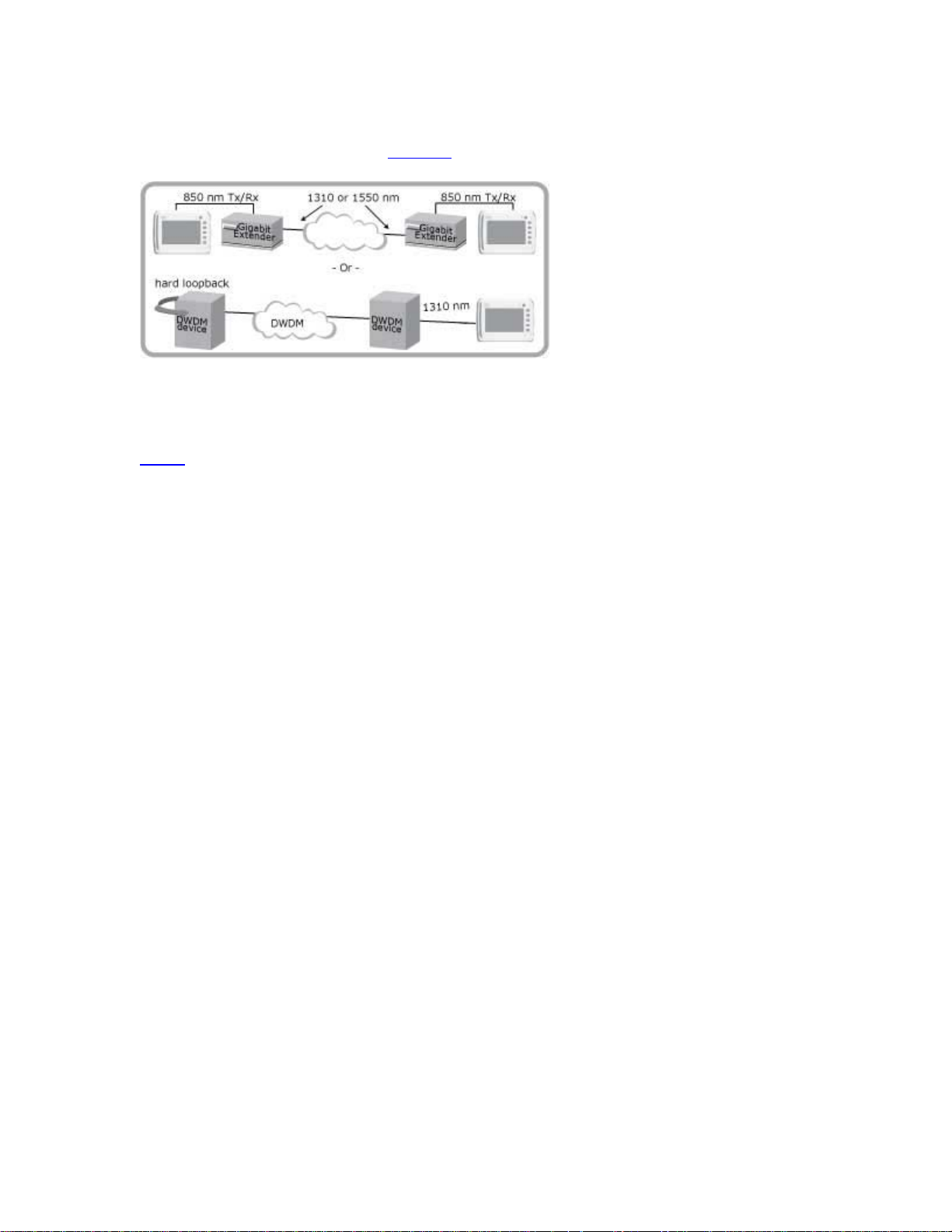
As test traffic is not passing through a Layer 2 (or higher) device, a Layer 1 test can
be performed with a single STT at one end and a hardware loopback, such as a patch
cord, at the far end.
Alternatively, the test can be performed with two STT units, one at each end of the
connection.
See the Application Diagram
Many networks, such as Ethernet over SONET/SDH (EOS), are not true Layer 1
networks, in that they require proper Ethernet framing. Only perform a Layer 1 test
when you are certain that framing is not required. Many problems with Layer 1
testing can be corrected by performing a Layer 2 test
How to Perform Layer 1 BER Testing
1. From the drop down menu, select Throughput as the test type.
2. Configure the port.
RJ-45 - Fast Ethernet
Augo-Negotiation: On
Port Rate: Match the rate of the line under test; 10M, 100M, 1000M
Port Duplex: FULL
Pause: OFF
RJ-45 Polarity: AUTO
Pause Frame Delay: 0 ms
SFP - Gigabit Ethernet
Pause: Off
Pause Frame Delay: 0 ms
XFP - Gigabit Ethernet
Pause: Off
Pause Frame Delay: 0 ms
.
.
Remember to make sure the laser is on for testing.
3. Configure the Signal
Test Type: BERT
Test Layer: PRBS + CRC (Layer 1 Framed)
• Set the desired frame size.
Traffic Shape: Constant
• Set the Constant Bandwidth at 100%.
• Use the 2^31 test pattern.
Far End Tester Configuration
• If performing this test between two units back-to-back, configure both units
as above.
• If performing to a software loopback, configure the far end module as follows:
Test Mode: LOOP BACK
Mode: Manual
Layer: Layer 1
44
tab.
Page 51

• Otherwise, make sure the far end has a hardware loop back.
Start the test.
Throughput Testing
Press
The Summary Results window will open automatically. Wait a few moments and
you should see ’No Errors’ on the Summary tab.
then to start the BERT .
Where do you want to go next?
Throughput Summary Results
Throughput Aggregate Results
Throughput Stream Results
Working Desktop
Home
45
Page 52
XTT 5000 User's Manual
L1 BERT Diagram Home
Layer 1 BERT Applications
Where do you want to go next?
Home
46
Page 53

Throughput Testing
Layer 2 BERT Application Home
In Layer 2 Throughput testing, you can run a BERT between two testers.
See the application diagram
Layer 2 devices (switches) keep track of MAC address information in order to forward
traffic to the appropriate port, therefore each test set has to be configured with valid
source and destination MAC address.
Layer 2 testing is often performed to verify the quality of service provided over an
Ethernet network. Unlike a Layer 1 BERT, the Layer 2 BERT generates valid MAC
frames so that the test traffic can traverse through bridges and switches.
How to perform Layer 2 BER testing
Local Configuration
.
1. From the drop down menu
2. Configure the port.
RJ-45 - Fast Ethernet
Augo-Negotiation: On
Port Rate: Match the rate of the line under test; 10M, 100M, 1000M
Port Duplex: FULL
Pause: OFF
RJ-45 Polarity: AUTO
Pause Frame Delay: 0 ms
SFP - Gigabit Ethernet
Pause: Off
Pause Frame Delay: 0 ms
XFP - Gigabit Ethernet
Pause: Off
Pause Frame Delay: 0 ms
Remember to make sure the laser is on for testing.
3. Configure the Signal
Test Type: BERT
Test Layer: Layer 2: Framed
• Set the desired frame size.
4. Configure the Stream Table
5. Configure the Payload tab
Traffic Shape: Constant
• Set the Constant Bandwidth at 100%.
• Use the 2^31 test pattern.
tab.
, select Throughput as the test type.
.
.
Far End Tester Configuration
• If performing this test between two units back-to-back, configure both units
as above.
• If performing to a software loopback, configure the far end module as follows:
Test Mode: LOOP BACK
Mode: Manual
Layer: Layer 1
• Otherwise, make sure the far end has a hardware loop back.
47
Page 54

XTT 5000 User's Manual
Start the test.
Press
automatically. Wait a few moments and you should see ’No Errors’ on the Summary
tab.
then to start the BERT. The Summary Results window will open
Where do you want to go next?
Throughput Summary Results
Throughput Aggregate Results
Throughput Stream Results
Home
48
Page 55
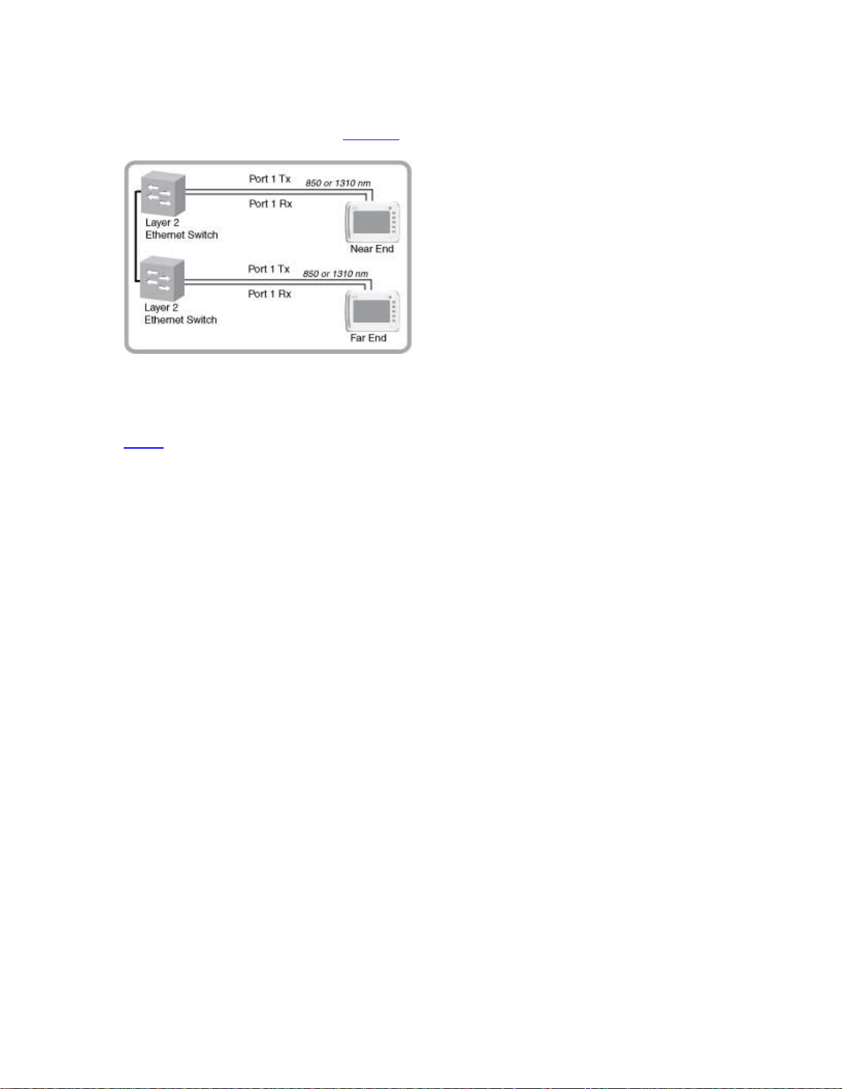
L2 BERT Diagram Home
Throughput Testing
Layer 2 BERT
Where do you want to go next?
Home
49
Page 56

XTT 5000 User's Manual
Throughput Signal Setup Home
The Signal graphic reflects the Ethernet frame; for L2 Framed, many frame elements
may be chosen from; see the Frame Setup
Choose a port
Before you begin testing, make sure the link is up.
Parameter Options Details
Test
Type
Layer L1 64B/66B,L1 8B/10B: Unframed
and configure the Stream Table (L2 Framed only).
BERT: Out-of-service testing; traffic
would be disrupted; perform a
throughput/BER test.
LIVE: Take statistics on frames, but
does not look for pattern
synchronization or bit errors.
signal. Continuous bits without
framing, containing 8B/10B line coding
for RJ-45 and SFP ports.
L2 PRBS+FCS: Layer 2 Framed.
The BERT is performed at OSI Layer 1
(physical layer), using the FCS or the
CRC field defined for an Ethernet
frame, without the MAC header.
L2:Framed: The BERT is performed at
OSI Layer 2 (data link).
tab.
Select the type of test.
BERT Note: The key
metrics are utilization
and lost frames. This is
the basic configuration.
Select the test layer.
L1: Unframed Note:
Configure the Pattern
L2: PRBS+FCS Note:
Configure the Pattern
and Traffic Shape
L2: Framed Note:
Configure the Stream
Table.
.
.
To send loopback commands in a test, press the 'Loop Control' ( ) button in the
Action Bar
To start the test, press 'Apply' (
will appear.
Select Throughput from the drop down menu
.
), then 'Start' ( ). The results Summary screen
.
Where would you like to go next?
Throughput Applications
Ethernet Frame Type
Throughput Summary Results
Throughput Aggregate Results
Throughput Stream Results
Throughput Test Setup
Working Desktop
Home
50
Page 57
Throughput Testing
Stream Table Setup Home
• Each stream may be configured independently. See Auto Fill to configure multiple
streams.
• Throughput tests support up to 16 streams. RFC 2544 tests support one stream.
• Visit the Technology Overview
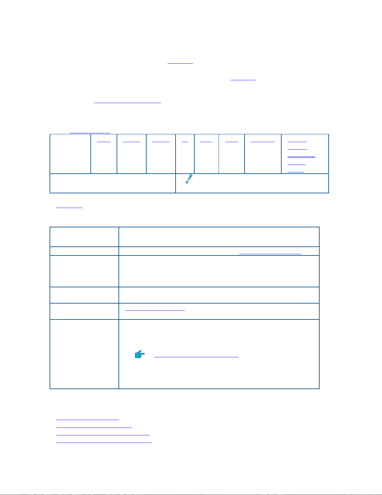
To configure a stream, tap a stream row. The Stream Number X window will pop
up, for configuring the stream in detail. When there are multiple streams, the
window will have scroll arrows for moving between Stream Number x windows.
The Frame Setup
MAC in
tab appears on top. Configure each tab on the window.
MAC VLAN MPLS IP TCP UDP Payload Traffic
MAC^
^Available at a future date.
Rx Filter
: Filter on received messages.
for information on frame components and more.
Shape*:
Constant
,
Ramp
Burst
*
Traffic shaping is not available in Layer
1, Unframed mode.
,
Stream Table Buttons
Button
Function
'Structure' Tap a frame element in the table to configure the frame.
'Total Streams' View/set the number of streams in use. Use the Total
Streams keypad to enter a new quantity (1-16) of streams
for the table if necessary. The number in use is shown on
the 'Streams' button.
'Remove' Delete the highlighted stream and reduce the total number
of streams by one.
'Auto Fill' Automatically fill in the addresses of all streams in the
table.
'TPID/BERT ID'
Note: This is a
global settings;
all BERT streams
get the same ID.
Edit the TPID directly in the field if required; applies only
when VLAN is in use.
• 8100 is the standard IEEE 802.1Q/802.1P value.
• A TPID is available for each VLAN.
• Technology: VLAN Tagging
BERT ID: Ox40 to 0x8100.
• The XTT 5000 place the BERT ID value in the IP Header
(Identification field) s, the tester can easily identify
whether IP traffic is BERT traffic or not.
Where do you want to go next?
Configure the frame
Throughput Applications
Throughput Summary Results
Throughput Aggregate Results
51
 Loading...