

Page 1
WHEELCHAIR
FAUTEUIL ROULANT
ROLSTOEL
Helium &
Helium Pro
DIRECTIONS FOR USE
NOTICE D’UTILISATION
GEBRUIKSAANWIJZING
000690966.02
Page 2

IF YOU ARE VISUALLY IMPAIRED, THIS DOCUMENT CAN BE VIEWED IN PDF
FORMAT AT WWW.SUNRISEMEDICAL.CO.UK
SI VOUS SOUFFREZ DE DÉFICIENCE VISUELLE, CE DOCUMENT PEUT ÊTRE
CONSULTÉ EN FORMAT PDF SUR WWW.SUNRISEMEDICAL.FR
ALS U VISUEEL GEHANDICAPT BENT KAN DIT DOCUMENT OOK WORDEN
GELEZEN IN PDF-FORMAAT OP: WWW.SUNRISEMEDICAL.NL
Wheelchair Components
We at SUNRISE MEDICAL have been awarded the ISO-9001 certicate, which afrms the quality of our products at every stage, from R & D to
production. This products meet the requirements in accordance with EC guidelines. Options or accessories shown are available at extra cost.
Description du fauteuil
SUNRISE MEDICAL est certié ISO -9001, une norme qui garantit la qualité des produits à toutes les étapes, de la conception à la production, en passant par la recherche et le développement. Ce produit est conforme aux directives de la Communauté européenne. Les options
ou accessoires illustrés sont disponibles moyennant un coût supplémentaire.
Rolstoelonderdelen
SUNRISE MEDICAL heeft het ISO 9001 certicaat toegekend gekregen, een bewijs van de kwaliteit van onze processen in elk stadium, vanaf
het onderzoek en de ontwikkeling tot de productie. Deze producten voldoen aan de eisen in overeenstemming met de EG-richtlijnen. Getoonde
opties en accessoires zijn tegen betaling verkrijgbaar.
2
EN
FR
NL
Helium-Rev.7.0
Page 3
2
12
11
10
1
3
4
5
9
6
04
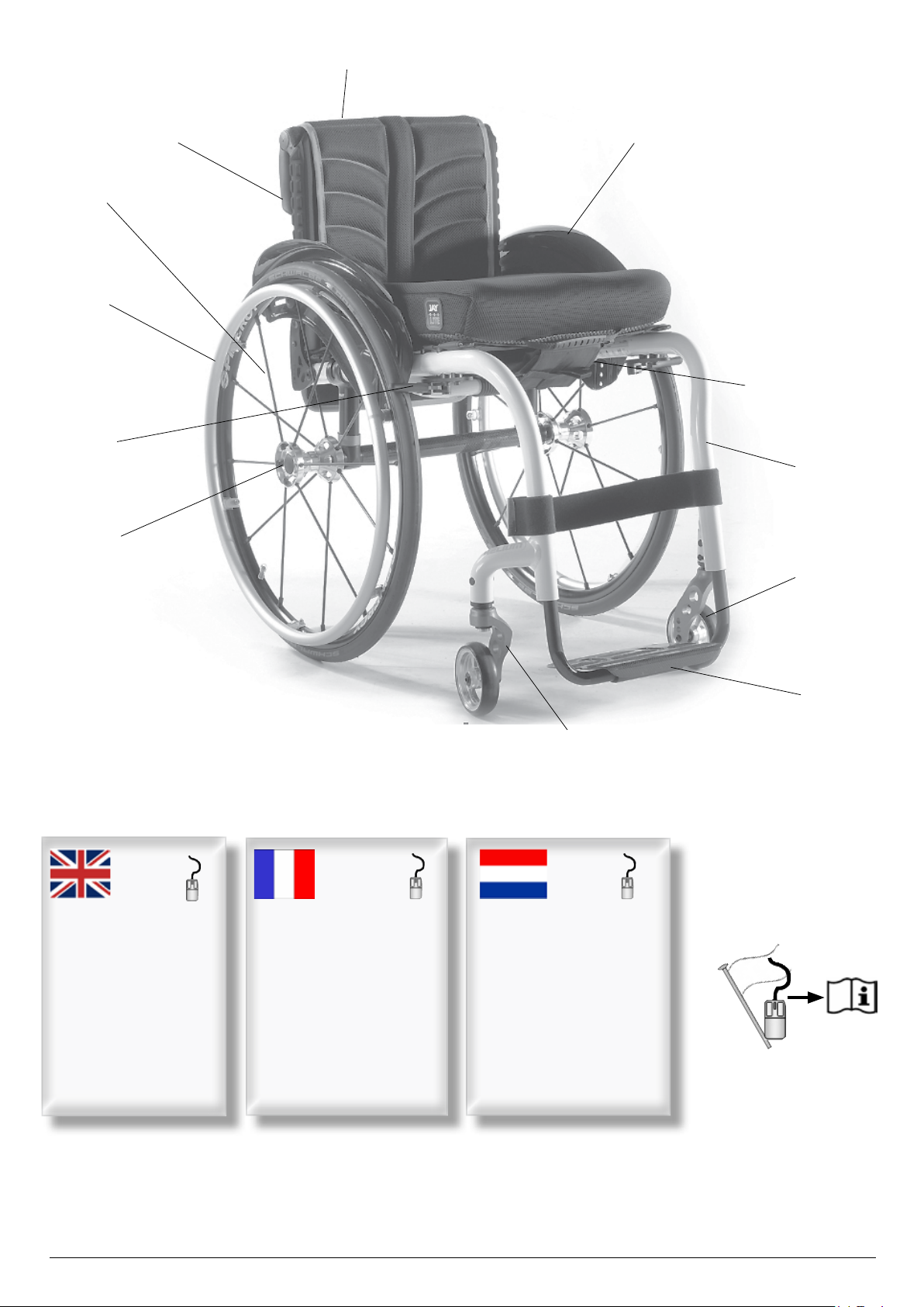
1. Push handles
2. Backrest upholstery
3. Sideguard
4. Seat sling
5. Footrest
6. Castors
7. Footboard
8. Fork
9. Quick-release axle
10. Wheel locks
11. Handrim
12. Rear wheel
29
1. Poignée de poussée
2. Toile de dossier
3. Protège-vêtement
4. Toile du siège
5. Repose-jambe
6. Roues avant
7. Plate-forme
8. Fourche
9. Axes à déverrouillage rapide
10. Freins
11. Main courante
7
8
54
1. Duwhandvatten
2. Spanbanden rug
3. Zijkant
4. Zittingbespanning
5. Voetsteun
6. Voorwielen
7. Voetplaten
8. Vork
9. Quick release assen
10. Remmen
11. Hoepel
12. Achterwiel
Helium-Rev.7.0
3
Page 4
Table of Contents
Definitions
Table of Contents 4
Definitions 4
Foreword 5
Use 5
Area of Application. 5
1.0 General safety notes and driving limits 6
ENGLISH
2.0 Handling 8
3.0 Transporting the wheelchair 8
4.0 Options 8
Step Tubes 8
Brakes 8
Suspension System 10
Hand-Bike Axle Adjustment 11
Helium centre of gravity setting 12
Helium Pro centre of gravity setting 12
Footplate Adjustment 13
Seat 13
Options - Snoll on 13
Castors 14
Wheel Alignment 14
Backrest 15
Sideguards 17
Push handle 18
Anti-tip tubes 18
Crutch Holder 19
Pelvic Restraint Belt 19
5.0 Tyres and Mounting 20
6.0 Maintenance and care 20
7.0 Disposal / Recycling of Materials 21
8.0 Trouble-shooting 21
9.0 Transportation 22
10.0 Nameplate 24
11.0 Warranty 24
12.0 Technical Data 25
13.0 Torque 28
3.1 Denitions of words used in this manual
Word Definition
Advice to the user of potential risk of
DANGER!
WARNING!
CAUTION!
NOTE: General advice or best practice
serious injury or death if the advice
is not followed
Advice to the user of a risk of injury
if the advice is not followed
Advice to user that potential
damage to equipment may occur if
the advice is not followed
Reference To Additional
Documentation
NOTE:
The wheelchairs shown and described in this user guide may
not correspond in every detail exactly to your own model.
However, all instructions are completely relevant, regardless of
possible detail differences.
The manufacturer reserves the right to alter without notice any
weights, measurements or other technical data shown in this
manual. All figures, measurements and capacities shown in this
manual are approximate and do not constitute specifications.
4
NOTE:
Please keep a note of your local service agent’s address and
t e le p h on e nu m b er i n t h e sp a ce p r ov i de d .
In the event of a breakdown, contact them and try to give all
relevant details so they can help you quickly.
Dealer signature and stamp
Helium Rev.7.0
Page 5

Foreword
Use
Dear Customer,
We are very happy that you have decided in favour of a highquality product from SUNRISE MEDICAL.
This owner's manual will provide numerous tips and ideas so
that your new wheelchair can become a trustworthy and reliable
partner in your life.
For Sunrise Medical, it is very important that we have a good
relationship with our customers. We like to keep you up-to-date
about new and current developments at our company. Keeping
close to our customers means: fast service, as little red tape as
possible, working closely with customers. When you need
replacement parts or accessories, or if you just have a question
about your wheelchair – we are there for you.
We want you to be satisfied with our products and service. At
Sunrise Medical we are constantly working to develop our
products further. For this reason, changes can occur in our
palette of products with regard to form, technology and
equipment. Consequently, no claims can be construed from the
data or pictures contained in this user’s manual.
The management system of SUNRISE MEDICAL is certified
to EN ISO 9001, ISO 13485 and ISO 14001.
As the manufacturer, SUNRISE MEDICAL,
declares that the lightweight wheelchairs
conform to the 93/42/EEC / 2007/47/EEC
guideline.
Please contact your local, authorised SUNRISE MEDICAL
dealer if you have any questions concerning the use,
maintenance, or safety of your wheelchair.
In case there is no authorised dealer in your area,
or you have any questions about product safety and product
recalls, contact Sunrise Medical either in writing or by telephone
or find the information on www.sunrisemedical.co.uk
Wheelchairs are exclusively for a user who is unable to walk or
has limited mobility, for their own personal use, when selfpropelling and being moved by a third party (pushed by
attendant) within the home and outdoors.
The maximum weight limit (includes the user and any
weight of accessories fitted to the wheelchair) is marked on
the serial number label, which is affixed to the Axle Tube
below the seat.
Warranty can only be taken on if the product is used under the
specified conditions and for the intended purposes.
The intended lifetime of the wheelchair is 5 years.
Please DO NOT use or fit any 3rd party components to the
wheelchair unless they are officially approved by Sunrise
Medical.
Area of Application.
The variety of fitting variants as well as the modular design
mean that it can be used by those who cannot walk or have
limited mobility e.g. because of:
• Paralysis
• Loss of extremity (leg amputation)
• Extremity defect deformity
• Joint contractures/joint injuries
• Illnesses such as heart and circulation deficiencies,
disturbance of equilibrium or cachexia as well as for elderly
people who still have the strength in the upper body.
ENGLISH
IMPORTANT:
DO NOT USE YOUR WHEELCHAIR UNTIL THIS
MANUAL HAS BEEN READ AND UNDERSTOOD.
Sunrise Medical
Thorns Road
Brierley Hill
West Midlands
DY5 2LD
England
Phone: 0845 605 66 88
Fax: 0845 605 66 89
www.SunriseMedical.co.uk
When considering provision, please also note the body size,
weight, physical and psychological constitution, the age of the
person, living conditions and environment.
Helium Rev.7.0
5
Page 6
1.0 General safety notes and driving limits
ENGLISH
The engineering and construction of this wheelchair has been
designed to provide maximum safety. International safety
standards currently in force have either been fulfilled or
exceeded in parts. Nevertheless, users may put themselves at
risk by improperly using their wheelchairs. For your own safety,
the following rules must be strictly observed.
Unprofessional or erroneous changes or adjustments increase
the risk of accident. As a wheelchair user, you are also part of
the daily traffic on streets and pavements, just like anyone else.
We would like to remind you that you are therefore also subject
to any and all traffic laws.
Be careful during your first ride in this wheelchair. Get to know
your wheelchair.
Before each use, the following should be checked:
• Quick-release axles on the rear wheels
• Velcro on seats and backrests
• Tyres, tyre pressure and wheel locks.
Before changing any of the adjustments of this wheelchair, it is
important to read the corresponding section of the user’s
manual.
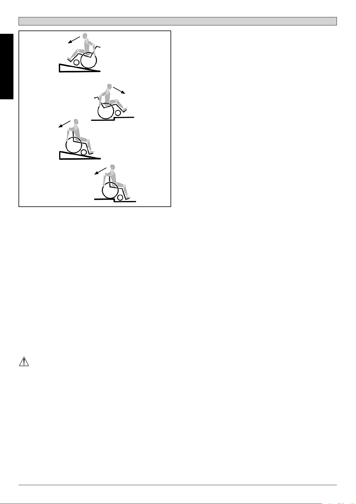
It is possible that potholes or uneven ground could cause this
wheelchair to tip over, especially when riding uphill or downhill.
When riding forwards over a step or up an incline, the body
should be leaning forward.
DANGER!
• NEVER exceed the maximum load of 125 kg for driver plus
any items carried on the wheelchair. Please note the weight
information for lighter weight options, which are quoted
separately. If you exceed the maximum load, this can lead
to damage to the chair, or you may fall or tip over, lose
control and may lead to serious injury of the user and other
people.
• When it is dark, please wear light clothing or clothing with
reflectors, so that you can be seen more easily. Make sure
that the reflectors on the side and back of the wheelchair
are clearly visible. We would also recommend that you fit
an active light.
• To avoid falls and dangerous situations, you should first
practice using your new wheelchair on level ground with
good visibility.
• When getting on or off the wheelchair, do not use the
footboards. These should be flipped up beforehand and
swung to the outside as far as possible. Always position
yourself as close as possible to the place where you wish
to sit.
• Only use your wheelchair properly. For example, avoid
travelling against an obstacle without braking (step, kerb
edge) or dropping down gaps.
• The wheel locks are not intended to brake your wheelchair.
They are only there to ensure that your wheelchair does
not begin rolling unintentionally. When you stop on uneven
ground, you should always use the wheel locks to prevent
such rolling. Always apply both wheel locks; otherwise,
your wheelchair could tip over.
• Explore the effects of changing the centre of gravity on the
behaviour of the wheelchair, for example on inclines,
slopes, all gradients or when overcoming obstacles. Do this
with the secure aid of a helper.
• With extreme settings (e.g. rear wheels in the most forward
position) and less than perfect posture, the wheelchair may
tip over even on a level surface.
• Lean your upper body further forward when going up
slopes and steps.
• Lean your upper body further back when going down
slopes and steps. Never try to climb and descend a slope
diagonally.
• Avoid using an escalator which may lead to serious injury
in the event of a fall.
• Do not use the wheelchair on slopes > 10°. The Dynamic
safe slope is dependent on the chair configuration, the
user#s abilities and the style of riding. As the user’s abilities
and style of riding cannot be pre-determined then the max
safe slope cannot be determined. Therefore this must be
determined by the user with the assistance of an attendant
to prevent tipping. It is strongly recommended that
inexperienced users have anti-tip tubes fitted.
• It is possible that potholes or uneven ground could cause
this wheelchair to tip over, especially when riding uphill or
downhill.
• Do not use your wheelchair on muddy or icy ground. Do not
use your wheelchair where pedestrians are not allowed.
• To avoid hand injuries do not grab in between the spokes
or between the rear wheel and wheel lock when driving the
wheelchair.
• In particular when using lightweight metal handrims, fingers
will easily become hot when braking from a high speed or
on long inclines.
• Riding sideways on to a slope or incline, increases the
possibility of the wheelchair tipping over sideways.
• Only attempt stairs with the help of an attendant. There is
equipment available to help you, e.g. climbing ramps or
lifts, please use them. If there is no such equipment
available, then the wheelchair must be tipped and pushed,
never carried, over the steps (2 helpers). We recommend
that users over 100 kg in weight do not use this stairway
manoeuvre!
• In general, any anti-tip tubes fitted must be set beforehand,
so that they cannot touch the steps, as otherwise this could
lead to a serious tumble. Afterwards the anti-tip tubes must
be set back to their correct position.
• Make sure that the attendant only holds the wheelchair
using securely mounted parts (e.g. not on the footrests or
the sideguards).
• This wheelchair is not designed to be used whilst weight
training and/or when using dumbbells. Only use equipment
specifically designed for this purpose.
• Do not lift or carry the wheelchair by the backtubes or the
pushhandles.
• When using the lifting ramp make sure that the anti-tip
tubes fitted are positioned outside the danger area.
• Secure your wheelchair on uneven ground or when
transferring, e.g. into a car, by using the brakes.
6
Helium Rev.7.0
Page 7

• If and whenever possible, during a journey in a specially
fitted vehicle for disabled people, vehicle occupants should
use the seats in the vehicle and the appropriate restraint
system. This is the only way to ensure that occupants will
have the maximum protection if there is an accident. When
using safety elements offered by SUNRISE MEDICAL and
using a specially designed safety system, lightweight
wheelchairs can be used as a seat when being transported
in a specially fitted vehicle. (See the Chapter on
“Transportation”).
• Depending on the diameter and setting of the castors, as
well as the centre of gravity setting of the wheelchair, the
castors may begin to wobble at high speeds. This can lead
to the castors being blocked and the wheelchair may tip
over. Therefore, please make sure that the castors are
adjusted correctly (see the Chapter "Castors"). In particular,
do not travel on an incline without brakes, travel at a
reduced speed. We recommend that novice users use antitip tubes.
• Anti-tip tubes should prevent the chair tipping over
backwards unintentionally. Under no circumstances should
they take the place of transit wheels, and be used to
transport a person in a wheelchair with the rear wheels
removed.
• When reaching for objects (which are in front of, to the side
or behind the wheelchair) make sure that you do not lean
too far out of the wheelchair, as if you change the centre of
gravity there is a risk of tipping or rolling over. The hanging
of additional load (back pack or similar items) onto your
chair backposts can affect the rearward stability of your
chair, especially when used in combination with recliner
backrests. This can cause the chair to tip backwards
causing injury.
• Adjustments to your wheelchair, particularly to safetyrelated components must be carried out by an approved
dealer. This applies to adjustments to wheel locks, anti-tip
tubes, backrest angle and height, lower leg length, COG,
lap belt, rear wheel toe-in and camber, seat height as well
as toe-in and directional stability of the castor fork.
• When using mobility accessories fitted to the wheelchair
such as handbikes, electronic power assist, etc, make sure
that your wheelchair is fitted with the appropriate castor
forks, approved for this use. Please contact your dealer if
you have any questions.
• Do not fit any unauthorized electronic equipment, powered
or mechanically operated mobility drives, hand-bike or any
other device that changes the intended use or the structure
of the wheelchair.
• Any combination with other medical devices requires the
approval of Sunrise Medical.
• Please note that in certain configurations the wheelchair
may exceed a width of 700 mm. If this is the case, under
certain circumstances, it may not be possible to use some
or all of the available escape routes from a building. It may
be more difficult or impossible to travel on public transport.
• For thigh amputees you must use anti-tip tubes.
• Before setting off, check that your tyre pressure is correct.
For rear wheels it should be at least 3.5 bar (350 kPa). The
max. pressure is indicated on the tyre. The knee-lever
brakes will only work if there is sufficient tyre pressure and
if the correct setting has been made (see the Chapter on
“Brakes”).
• If the seat and back sling are damaged, you must replace
them immediately.
• Be careful with fire, in particular with burning cigarettes.
Seat and back slings can be set alight.
• If the wheelchair is subject to direct sunlight for a long
period of time, then parts of the wheelchair (e.g. frame,
legrests, brakes and sideguard) may become hot (>41°C).
• Always make sure that the quick-release axles on the rear
wheels are set properly and lock in. If the button on the
quick-release axle is not pressed in, the rear wheel cannot
be removed.
WARNING!
• The effect of the knee-lever brake as well as the general
driving characteristics are dependent on tyre pressure. The
wheelchair is significantly lighter and easier to manoeuvre
when the rear wheels are pumped up correctly and both
wheels have the same pressure.
• Make sure that your tyres have sufficient tread! Please note
that you are subject to any and all traffic laws when driving
in public traffic.
• Always be careful with your fingers when working or
adjusting the wheelchair!
WARNING!
CHOKING HAZARD – This mobility aid uses small parts which
under certain circumstances may present a choking hazard to
small children.
The wheelchairs shown and described in this user guide may
not correspond in every detail exactly to your own model.
However, all instructions are completely relevant, regardless of
possible detail differences.
The manufacturer reserves the right to alter without notice any
weights, measurements or other technical data shown in this
manual. All figures, measurements and capacities shown in this
manual are approximate and do not constitute specifications.
Sunrise Medical is ISO 9001 certified, which ensures quality at
all stages of the development and production of our products.
This product complies with the standards set forth in EU
directives. Optional equipment and accessories are available at
extra charge.
ENGLISH
Helium Rev.7.0
7
Page 8

2.0 Handling
Quick-release axles on rear
wheel
The rear wheels are equipped with
quick-release axles.
The wheels can thus be installed or
removed without using tools.
To remove a wheel, simply depress
the quick-release button on the axle
ENGLISH
(1) and pull it out (Fig. 2.1).
CAUTION!
Hold the quick-release button on the axle depressed when
inserting the axle into the frame to mount the rear wheels.
Release the button to lock the wheel in place. The quick-release
button should snap back to its original position.
Fig. 2.1
1
3.0 Transporting the wheelchair
Transporting the wheelchair
Removing the rear wheels will keep the wheelchair as compact
as possible. The backrest can be folded down by pulling the cord
(1) (see picture 3.2) located on the backrest (Fig. 3.1 and 3.2).
Getting into your wheelchair on your own
• Push the wheelchair to a wall or a solid piece of furniture
• Apply the brakes
• The user can lower themselves into the wheelchair
• Then position the feet in front of the heel straps
(Fig. 4.1).
Getting out of your wheelchair on your own
• Apply the brakes
• With one hand on the wheel or side guard, the person should
lean forwards slightly, to transfer the body weight to the front
edge of the seat and then push up to an upright position with
both feet firmly on the floor and one foot behind the other (Fig.
4.2).
Fig. 4.1
Fig. 4.2
Fig. 3.1
In this state the wheelchair can be lifted by the frame tubes and
the seat sling. When transporting the unoccupied wheelchair in
a vehicle, it should be tied down or strapped in.
Fig. 3.2
1
4.0 Options
Step Tubes
Step Tubes
Step tubes are used by attendants to push a wheelchair over an
obstacle. Simply step on the tube to push a wheelchair, for
example, over a kerb or step.
WARNING!
Sunrise Medical strongly recommends the use of a step tube on
any model where attendant use is the predominant intended
use. Damage to the backposts may occur if you constantly use
the backpost without a step tube, as a lever to pull back on to tip
the wheelchair.
Brakes
Fig. 4.3
CAUTION!
Braking power can be
affected by incorrect fitting and
adjustment of the brakes, as well as tyre pressure which is too
low.
Wheel Locks
Your wheelchair is equipped with two wheel locks. They are
applied directly against the tyres. To engage, press both wheel
lock levers forward against the stops. To release the locks, pull
the levers back to their original positions.
Braking power will decrease with:
• Worn tyre tread
• Tyre pressure that is too low
• Wet tyres
• Improperly adjusted wheel locks.
Fig. 4.4
3.0 mm
8
Helium Rev.7.0
Page 9
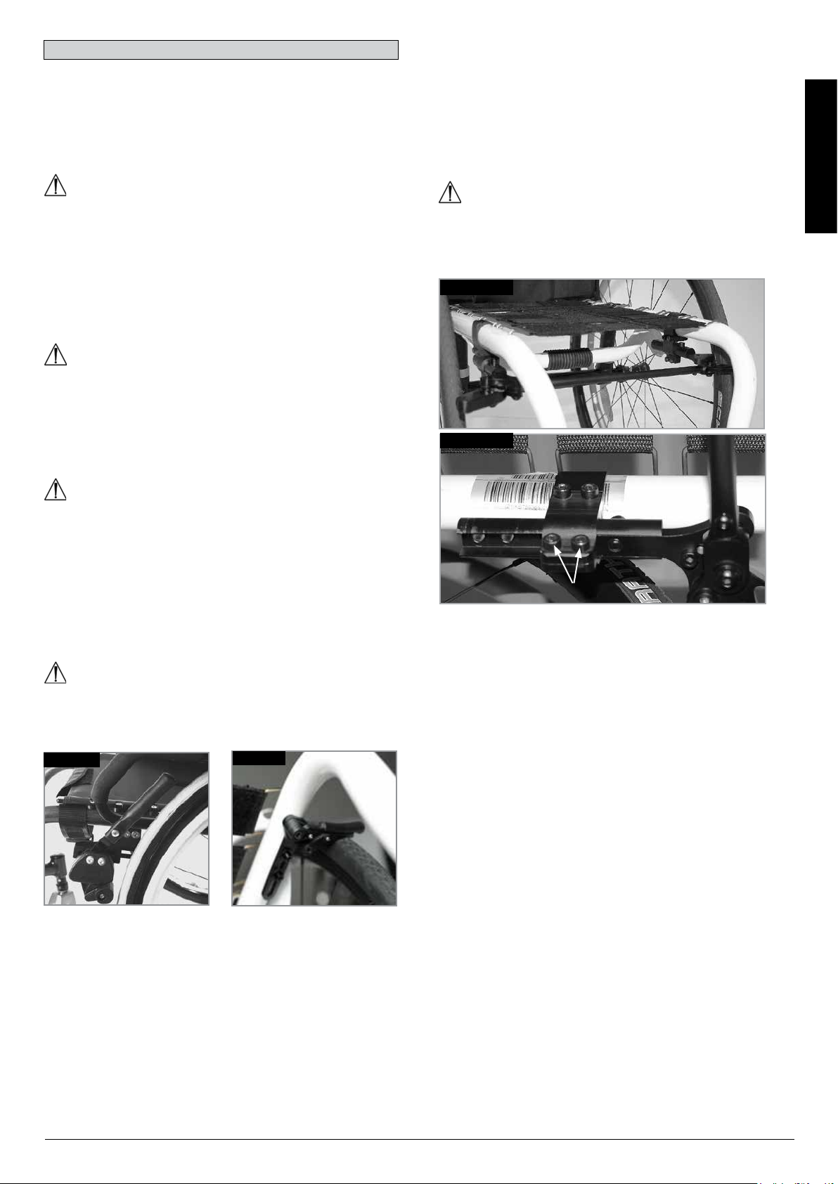
Brakes...
The wheel locks have not been designed to be used as brakes
for a moving wheelchair. The wheel locks should therefore never
be used to brake a moving wheelchair. Always use the handrims
for braking. Make sure that the interval between the tyres and
wheel locks complies with given specifications. To readjust,
loosen screw and set the appropriate interval. Then re-tighten
the screw, (Fig. 4.3 and 4.4).
CAUTION!
After each adjustment of the rear wheels, check the interval to
the wheel locks and readjust if necessary.
Brake lever extension
The longer lever helps to minimize the effort needed to set the
wheel locks.
The brake lever extension is screwed to the brakes. By raising
this, it can be flipped forward (Fig. 4.5).
CAUTION!
Mounting the wheel lock too close towards the wheel will result
in a higher effort to operate. This might cause the brake lever
extension to break!
The One-arm Wheel Lock
The one arm wheel lock is underneath the seat sling and is
operated by pulling the brake lever, which is located on the left
or right side, towards the rear, in the direction of the tyre. For
the brakes to work properly, this must be pulled until it reaches
the stop, (Fig. 4.6.1)
Adjustment
To adjust the brake, loose the screws (1) and mount the wheel
lock where it will work in a proper way (Fig. 4.6.2).
ENGLISH
CAUTION!
Incorrect mounting of the one arm wheel lock can lead to
serious injury of the user and other people.
Fig. 4.6.1
Leaning onto the brake lever extension while transferring will
cause the lever to break! Splashing water from tires might cause
the wheel lock to malfunction.
CAUTION!
Incorrect mounting of the wheel lock will result in a higher effort
to operate.
This might cause the wheel lock extension lever to break!
Compact Wheel Lock
Compact wheel locks are underneath the seat sling and are
operated by pulling the wheel locks towards the rear, in the
direction of the tyre. For the brakes to work properly, this must
be pulled until it reaches the stops, (Fig. 4.6).
CAUTION!
The mounting bolts for the brakes must not be loosened and/or
re-tightened.
Fig. 4.5
Fig. 4.6
Fig. 4.6.2
1
Helium Rev.7.0
9
Page 10

Suspension System
CAUTION!
WARNING!
Rear suspension can affect the stability of the wheelchair. To
avoid a fall, use a spotter and/or anti-tip tubes when becoming
familiar with new equipment.
1. Tuning the 4-Link Rear Suspension
ENGLISH
a. to stiffen the suspension, turn the spring preload adjustor (E)
clockwise (looking up at the suspension system from
underneath the wheelchair).
b. to soften the suspension, turn the spring preload adjustor (E)
counter-clockwise (looking up at the suspension system from
underneath the wheelchair).
2. Alignment of Suspension Link Arms
Do not adjust the link arms (F, Fig. 4.10). These are set at the
factory to ensure proper tracking and performance of the 4-Link
suspension system.
(see next page).
Setting the toe-in/toe-out to zero (using the factory fitted
adjuster)
Loosen the Allen screws (G), (2 per side), that
secure the axle tube on both sides. Observe the ball in the
transparent adjuster in the centre of the axle tube, then turn the
axle tube (C), until the ball is exactly centred at the lowest point
of the adjuster. The toe is now set at zero (Fig. 4.7, 4.10).
When turning the 4-Link Rear Suspension, make one change at a
time and write down each change. This takes patience, but allows
you to understand how each change affects the ride of the
wheelchair in conjunction with rear suspension.
NOTE– The lower shock mount is designed to have a loose feel,
this is by design to allow for proper suspension travel.
CAUTION!
Under no circumstances, loosen the screw connection between
the axle clamp and the shock absorber.
3. Maintenance
The maintenance requirements listed below should be followed
along with general wheelchair maintenance shown in Section 6.0.
a. do not apply lubrication to shock end bushings or coils.
b. you can apply lubrication to the link ends after cleaning with a
mild soap and soft
brush.
c. use a soft brush to clear any dirt or debris from coil system.
d. never use a high-powered washer for cleaning the 4-Link Rear
Suspension.
Before re-tightening the screws (G), check that
the flat surfaces of the camber adapter in the axle tube protrude
outside the axle tube clamp. The end of the cylindrical camber
adapter should be flush with the end of the axle tube. Tighten
the screws to a torque of 7 Nm
Setting the toe-in/toe-out to zero (using a 90° setting gauge)
Place the entire wheelchair on a flat
horizontal table or ground surface. Loosen the Allen screws (G)
(2 per side) which hold the axle tube on both sides of the axle
tube.
Then put the setting gauge at an angle of exactly 90° (e.g. a
carpenter’s square) on the flat surfaces of the camber adapter
(D) (Fig. 4.8, Fig. 4.9). Then turn the axle tube until the wrench
surfaces are exactly parallel to the upper surface of the setting
gauge (Fig. 4.8).
Before re-tightening the screws (G), check that
the flat surfaces of the camber adapter in the axle tube protrude
outside the axle tube clamp. The end of the cylindrical camber
adapter should be flush with the end of the axle tube. Tighten
the screws to a torque of 7 Nm
C
BALL
Fig. 4.7
Fig. 4.9
Fig. 4.8
D
B
Fig. 4.10
10
C
D
F
E
Helium Rev.7.0
PAR ALLEL
H
I
G
Page 11

Hand-Bike Axle Adjustment
Hand-Bike-Axle
It is necessary to adjust the hand-bike axle to bias the centre of
gravity rearwards. This allows safe use of a hand-bike
accessory, (Fig. 4.10.1).
Fig. 4.10.2
DANGER!
Using a hand-bike without the hand-bike axle makes the
wheelchair unstable and can lead to serious injury of the user
and other people.
Fig. 4.10.1
ENGLISH
Fig. 4.10.3
Fig. 4.10.4
Hand-Bike Reinforcement Kit
To assemble the hand-bike reinforcement kit:
• Insert the nipple at one end of the cable into the receptor
at the front of the frame, (Fig. 4.10.2).
• Insert the nipple at the other end of the cable into the
receptor at the rear of the frame, (Fig. 4.10.3).
• Insert the tensioner tool, (A), into the cable receptor at the
rear of the frame, (Fig. 4.10.4).
• Move the tensioner tool, (A), upwards until the receptor
and the front tube, (B), just starts to move towards the
rear, (Fig. 4.10.5).
• Hold the cable under tension with the tensioner tool and
tighten the screw on the rear cable receptor, (Fig. 4.10.5).
• Repeat the process for the other side.
WARNING!
The tension of both cables must be checked for tightness
before and after each use of the hand-bike.
A
Fig. 4.10.5
A
B
Helium Rev.7.0
11
Page 12
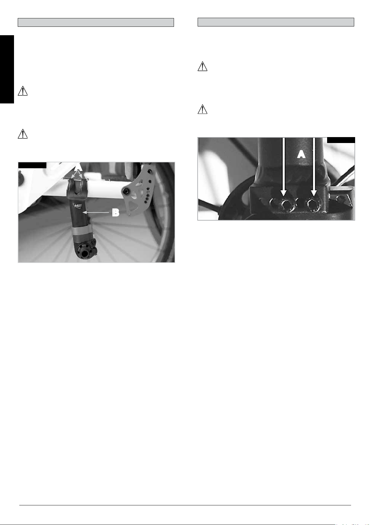
Helium centre of gravity setting
Helium Pro centre of gravity setting
Remove the rear wheels. Undo both Allen screws (A) on the
top of the axle stem (B) on both sides of the wheelchair, (Fig.
4.10.6). Then push the complete unit out of the axle and push
both axles stems forwards on the frame, (in terms of the
direction of travel), for a more active COG, or backwards for a
more passive, stable COG. Then re-tighten the screws (A) on
both sides to a torque of 5 Nm. Now adjust the side guards and
brakes to the new wheel position.
ENGLISH
CAUTION!
Please note that the tipping behaviour of the wheelchair will
change if the COG has been changed. This may mean that you
need to use anti-tip tubes.
DANGER!
The brakes must be adjusted to the new COG position.
Fig. 4.10.6
A
B
To adjust the centre of gravity (COG) remove the 2 screws, (A)
and move the bracket into preferred position, (Fig. 4.10.7). Refit
and tighten the screws (5 Nm).
CAUTION!
Please note that the tipping behaviour of the wheelchair will
change if the COG has been changed. This may mean that you
need to use anti-tip tubes.
DANGER!
The brakes must be adjusted to the new COG position.
Fig. 4.10.7
A
12
Helium Rev.7.0
Page 13
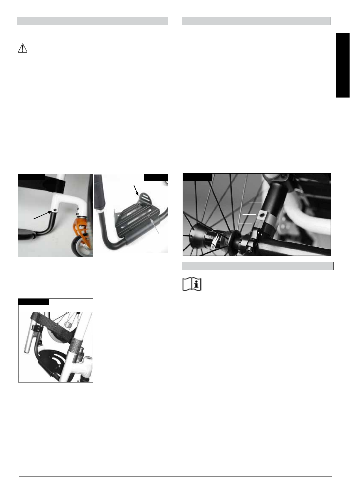
Footplate Adjustment
Adjusting The Footrest
WARNING!
• Do not stand on the footboard! Even if the user is sitting in
the chair, there is still a risk of tipping over and injury.
• When transferring, do not stand on the footboard, there is a
risk of tipping over and injury.
Releasing the screw (1) will allow you to adjust the footrest to
correspond to the length of your lower leg and re-attach the
footrest. The angle of the footrest may be individually adjusted
by loosening screws (2). The side protection (3) on the footrest
prevents the feet slipping off accidentally. Make sure that after
any adjustment work, all screws are tightened correctly (see the
page on torque) (Fig. 4.11 - 4.12).
Seat
Adjusting the seat height
To adjust the rear seat height release the Allen screws (1) (one
on each side), which fix the clamp to the axle stem (2).
Remove the spacer bracket (3), to adjust the seat height +/- 1
cm. For large adjustments, reduce the length of the axle stem
as required.
Tighten the 2 Allen screws to 7 Nm. (Fig. 4.14).
NOTE:
An adjustment to the castor angle may be necessary when
adjusting the rear seat height.
Seat Sling
To tighten the upholstery, please use the straps below the
upholstery.
ENGLISH
Fig. 4.11
3
Fig. 4.12
1
High-mount footrest
The high-mount footrest is fitted on the inner part of the frame
and permits a higher footrest position (Fig. 4.13).
Fig. 4.13
Fig. 4.14
2
1
3
2
Options - Snoll on
Please see the separate Owners' Manual for details of
the Snoll On accessory.
Helium Rev.7.0
13
Page 14

Castors
Wheel Alignment
Castor, Castor adapter, Castor fork
From time to time the wheelchair may veer slightly to the right or
left or the castors may flutter. This may be caused by the
following:
• Forward and/or reverse wheel motion has not been set
properly.
• The castor angle has not been adjusted properly.
ENGLISH
• Castor and/or rear wheel air pressure is incorrect; wheels do
not turn smoothly.
The optimum adjustment of the castors is required so that the
wheelchair runs in a straight line.
The castor plates must be re-adjusted, and the wheel locks must
be checked every time the rear wheel position has been altered.
Adjusting the castor
To ensure that both forks are set parallel, simply count the teeth
visible on both sides. After setting the castor fork, the teeth will
guarantee a secure position, allowing an adjustment of 16° in 2°
increments. Use the flat side on the front of the castor fork to
check for a right-angled position to the ground (Fig. 4.15).
The patented design allows the castor fork to be turned, so that
it can be reset at right-angles to the ground when the seat angle
is changed.
Setting the directional stability
Release the Allen screws (1) on the underside of the fork. You
can then undo the screw (2). You can now turn the black socket
(3) left or right.
Left – chair pulls to the left
Right – chair pulls to the right
Then tighten up the screw (2) again. Please set a 90° angle from
the fork to the floor.
Now tighten up the screw (1) again. (Fig. 4.16).
Fig. 4.15
Fig. 4.16
2
+8 -8
1
Adjusting the wheel alignment
Important: To achieve the very best movement, the rear wheels
must be adjusted to their optimum position, which means
correctly adjusting the wheel alignment.
To do this, measure the distance between both wheels front and
rear to ensure that they are parallel to one another.
The difference between both measurements should not exceed
5 mm.
To adjust the wheels to make them parallel, loosen the screws
and turn the axle sleeve accordingly. Make sure that after any
adjustment work, all screws are tightened correctly (see the
page on torque).
HELIUM tracking adjustment
Setting the toe-in/toe-out to zero
NOTE: A wheelchair with 0° camber cylinders cannot have toe-in
or toe-out. This setting is necessary only with 3° and 6° camber
cylinders.
The term "toe-in or toe-out" defines how well the rear wheels of
the chair are aligned in relation to the ground. This determines
how well the chair will run. Normal resistance or rolling
resistance is present when toe-in is set to zero.
To set toe-in/toe-out to zero: Loosen the Allen screw (1) (one on
each side), that secures the camber tube clamp. Check the ball
in the horizontal (2) plane and turn the angle tube (3) until the
ball is in the centre. Toe-in is now zero.
Before tightening the screws (1), check that the camber tube is
centred left-to-right. The gap should be the same on both sides,
or there should be no gap at all. Tighten the screws to 7 Nm.
(Fig. 4.17 - 4.19).
Adjusting the rear wheelbase width:
The rear wheelbase is defined as the distance between the
upper side of the rear wheels and the backrest tubes, and is
represented by factory setting (1.25 cm). This has to be
increased if a larger gap between the tyres and the optional
height-adjustable armrests has to be created (Fig. 4.20).
3
NOTE:When adjusting the rear wheelbase, adjust first one
wheel then the other. If both sides are loosened at the same
time, this will alter the toe-in/toe-out adjustment. To adjust the
rear wheelbase, the parts of the camber (4) move telescopically
into or out of the camber tube (5), and lock into place when they
reach the end. Loosen screw (6) (located closest to the camber
tube) on the left side of the chair. Move the quick-release axle
inwards or outwards to achieve the desired wheelbase. Tighten
the screws to 7 Nm. Repeat this procedure on the right side of
the chair and adjust the gap so that it is the same amount as on
the left side.
14
Helium Rev.7.0
Page 15

Fig. 4.17
Fig. 4.18
CAUTION!
When folding the backrest down, please make sure that your
fingers do not get caught.
1
Fig. 4.19
Fig. 4.20
3
5
4
6
BALL
2
Backrest
Angle-adjustable back
The backrest angle is adjusted by altering the position of the pin
in the backrest mounting. The pin (1) must be completely clicked
into place in the hole pattern on both sides, this gives you an
angle adjustment of 8.5°.
Fit the black plastic pins into the unused holes. To reach a
smaller angle increment (3.5°), you open the Allen key screw (2)
and re-set the screw into the second hole. Please use the
relevant torque force (see matrix) to tighten the screw (2).
This gives you 12° change in the back angle. Then move the pin
(1) in the opposite direction to the next hole, which gives you 12°
- 8°= 3.5° change. (Fig. 4.21)
To reduce the play in the backrest, the nut (1) can be released,
then the optimal position can be set using the set screw (2).
Then re-tighten the nut (1). (Fig. 4.22).
Fig. 4.21
2
1
Fig. 4.22
1
2
Adjustable Back Sling
The adjustable back sling can be adjusted for tension by using
several straps.
The back sling upholstery can be accessed from the inside via
an opening and can be padded to suit individual tastes, (Fig.
4.23).
Height-adjustable backrest
The backrest may be set to various back heights, in 25 mm
steps. The adjustment ranges are 250 - 300 mm, 300 - 350 mm,
350 - 400 mm and 400 - 450 mm. Release the screws (1+2) and
set the backrest to the desired height. Tighten up the screws
again (see the page on torque). (Fig. 4.24)
CAUTION!
Please note that the tipping behaviour of the wheelchair will
change if the backrest angle or backrest upholstery has been
changed. This may mean that you need to use anti-tip tubes.
Fig. 4.23
Fig. 4.24
1
ENGLISH
CAUTION!
The screws must be re-tightened. Otherwise the angle
adjustment will be lost.
Folding Backrest
Release the backrest by pulling the cord. At the same time, push
it forward to fold it down. To return the backrest to its original
position, this must be pulled back as far as possible until it locks
into place on both sides.
1
Helium Rev.7.0
15
Page 16
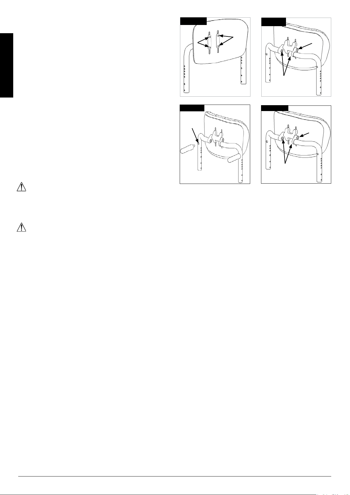
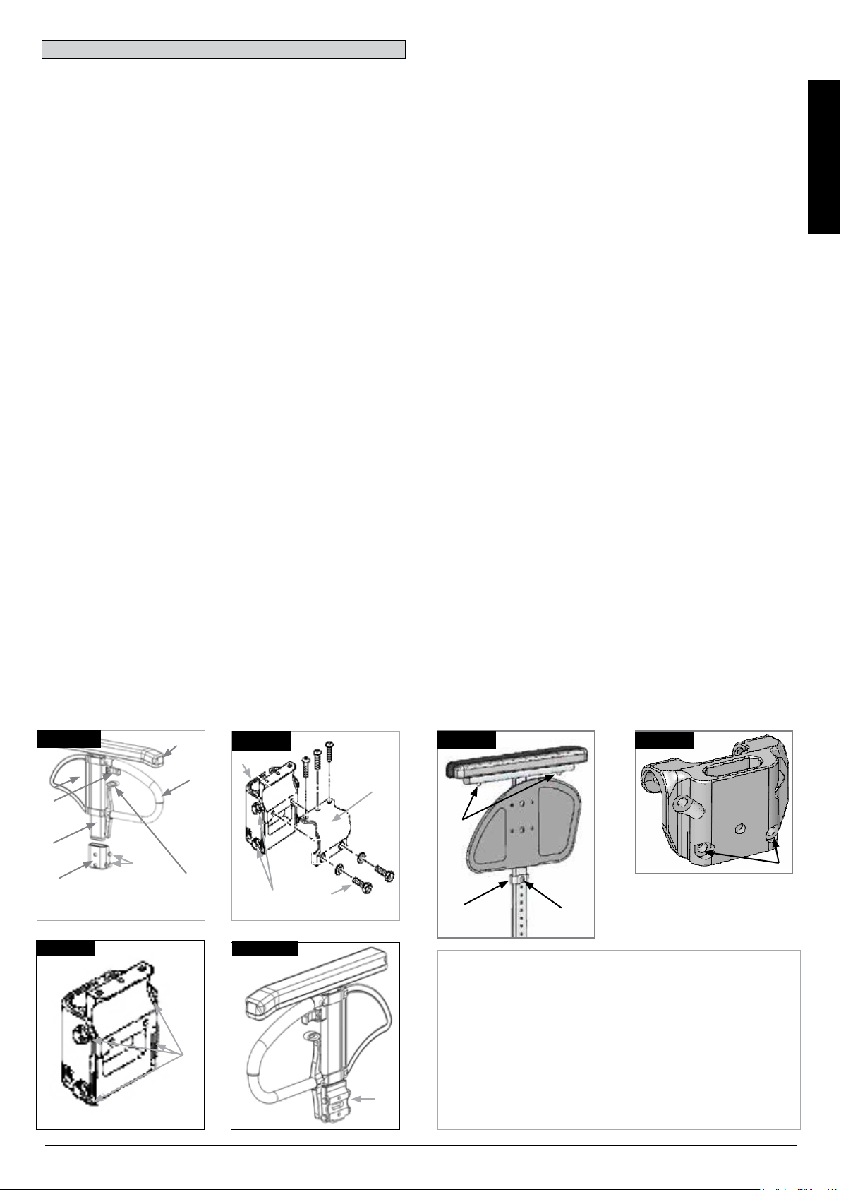
Freestyle Back
The Freestyle back can be adjusted in height, depth and angle
to provide maximum comfort and support.
Height adjustment:
Remove the back cushion to gain access to the adjustment
hardware. Loosen the 4 screws (1) using a 4 mm hex key and
move the back shell up or down to the desired height. Tighten
the screws to lock the adjustment and re-install the back
cushion.
ENGLISH
Fine Depth and Height adjustment
The Freestyle back adjustment system provides a maximum of
25 mm fine depth combined with a fine height adjustment .
Loosen the screws (2) using a 8 mm hex key and rotate the
back shell to the desired position. Tighten the screws with 20
Nm to lock the adjustment.
Angle adjustment
The Freeestyle back adjustment system allows the adjustment
of the backrest angle. Loosen the screws (3) using a 8 mm hex
key and rotate the back shell to the desired position. Tighten the
screws with 20 Nm to lock the adjustment.
Fig. 4.25
Fig. 4.27
A
Fig. 4.26
1
1
3
2
Fig. 4.28
20 Nm
In case some attendant support is required the removable push
handles can be screwed into position A.
WARNING!
Always make sure that the push handles are screwed in
completely.
WARNING!
The Freestyle back is not approved for using the wheelchair as
a seat in a car during transport.
20 Nm
16
Helium Rev.7.0
Page 17
Sideguards
Central support
Single Post Height-Adjustable Armrests
(Fig. 4.29 - 4.32).
1. Assembly
a. slide the outer armpost into the receiver mounted to the
wheelchair frame.
b. the armrest will automatically lock into place.
2. Height adjustment
a. rotate height release lever (2) to second stop.
b. slide armrest pad up or down to desired height.
c. return lever to locked position against arm post.
d. push arm pad (4) until upper arm post locks firmly into
place.
3. Removing the armrest
a. pull lever 3 and lift entire arm.
4. Replacing Armrest
a. slide armrest back into receiver until arm latches in place.
Armrest Receiver Attachment
(Fig. 4.29 - 4.32).
Adjusting Armrest Receiver Fit
To tighten or loosen the fit of the outer armpost in the receiver:
1. Loosen the four receiver adjustment bolts (9) on the sides of
the receiver.
2. With the armrest in the receiver (7), squeeze the receiver to
achieve the desired fit.
3. Tighten the four bolts (9). (16.3 Nm)
Position Adjustment
1. Loosen the two clamp bolts (10) until clamp is loose.
2. Slide armrest receiver to desired position.
3. Tighten
Installation: Slide the arm post into the receiver, located on the
wheelchair frame, until it stops
Height adjustment:
Slide the armrest post out of the receiver.
Adjust the position of the height adjustment bracket (1) by
removing the screw (2) and moving it to the desired position.
Re-fit the screw and tighten it.
Slide the arm rest post back into the receiver, (Fig. 4.32.1).
Armpad Position:
The armpad position can be adjusted by releasing the screws
(3), then moving the arm pad to the desired position. Re-tighten
the screws, (Fig. 4.32.1).
Adjusting Armrest Receiver
The tightness of the armrest receiver can be adjusted (tightened
/loosened) by means of the 2 screws (1) - (Fig. 4.32.2).
ENGLISH
Fig. 4.29
6
2
1
7
Fig. 4.31
4
Fig. 4.30
Fig. 4.32.1
Fig. 4.32.2
7
5
9
9
10
8
3
1
3
9
Fig. 4.32
9
10
1
Fig. 4.25 - 4.28 Parts key
1. Outer armpost
2. Height Release Lever
3. Release lever
4. Armrest Pad
5. Transfer bar
6. Sideguard
7. Receiver
7
8. Clamp
9. Receiver adjustment bolts
10. Clamp bolts
2
Helium Rev.7.0
17
Page 18

Push handle
Height-adjustable push handles
These handles are secured with pins to prevent them from
sliding out unintentionally. Opening the quick-release lever (1)
makes it possible to adjust the height of the push handles (2) to
meet your individual needs. As you move the lever, you will hear
a locking mechanism; you may now easily position the push
handle as desired. The nut on the tension lever determines how
tightly the push handles are clamped into place. If the nut is
ENGLISH
loose after adjusting the tension lever, the push handle will also
be too loose. Turn the push handle from side to side before use
to make sure that it is clamped securely enough into place. After
adjusting handle height, always clamp the tension lever (1)
securely into place. If the lever is not secure, injuries could result
when ascending stairs. (Fig. 4.33).
NOTE – If the height-adjustable push handles are not fitted
properly, there is a risk that these will develop "play" or that they
move out of position. Please make sure that the relevant screws
are tightened correctly.
Folding push-handles
If the push handles are not in use, they can be folded down by
depressing the button (2). When they are needed again, simply
flip them back up until they click into place. (Fig. 4.34).
2. Adjusting Anti-Tip Tubes
To achieve the correct ground clearance of approx. 1" to 2" (25
mm to 50 mm), the anti-tip tubes must be raised or lowered.
Press the anti-tip tube release button, so that both release pins
are drawn inwards. Move the inner tube up or down to slot into
the height holes provided. Release the button. Fit the second
anti-tip tube in the same way. Both wheels should be at the
same height. (Fig. 4.35).
DANGER!
Sunrise Medical Recommends Use Of Anti-Tip Tubes:
If the anti-tip tubes are not fitted, or have been fitted incorrectly,
there is a risk of tipping over and of injury.
Fig. 4.35
Fig. 4.33
Fig. 4.34
2
1
2
Anti-tip tubes
WARNING!
Sunrise Medical recommends anti-tip tubes for all chairs. When
fitting anti-tip tubes, use a torque of 7 Nm.
1. Slotting the anti-tip tubes into the clamp:
a. press the rear button on the anti-tip tube on the anti-tip tube
adaptor, so that both release pins are drawn inwards.
b. slot the anti-tip tubes (1) into the anti-tip tube adapter.
c. turn the anti-tip tubes downwards until the release pin locks
into the clamp.
d. fit the second anti-tip tubein the same way.
Active Anti-Tip tube/Flip Up
The active anti-tip tube is mounted on the left or right side of the
axle tube. By pushing it towards the axle tube, it can be flipped
downwards for operation, (Fig. 4.35.1).
WARNING!
Make sure that the anti-tip tube will lock in the final position. An
unlocked active anti-tip tube can lead to serious injury of the
user.
Fig. 4.35.1
18
Helium Rev.7.0
Page 19
Anti-tip tubes...
Pelvic Restraint Belt
Active Anti-Tip tubes For Sport
To remove the active anti-tip tubes for sport, press the button of
the quick release pin and pull it out. Now pull out the tube from
the anti-tip receiver, (4.35.2 - 4.35.3).
Fig. 4.35.2
Fig. 4.35.3
DANGER!
• Before using your wheelchair ensure the lap belt is worn.
• The lap belt must be checked on a daily
• basis to ensure it is free from any obstruction or adverse
wear.
• Always make sure that the lap strap is correctly secured
and adjusted prior to use. If the strap is too loose it could
cause the user to slip down and risk suffocation or cause
serious injury.
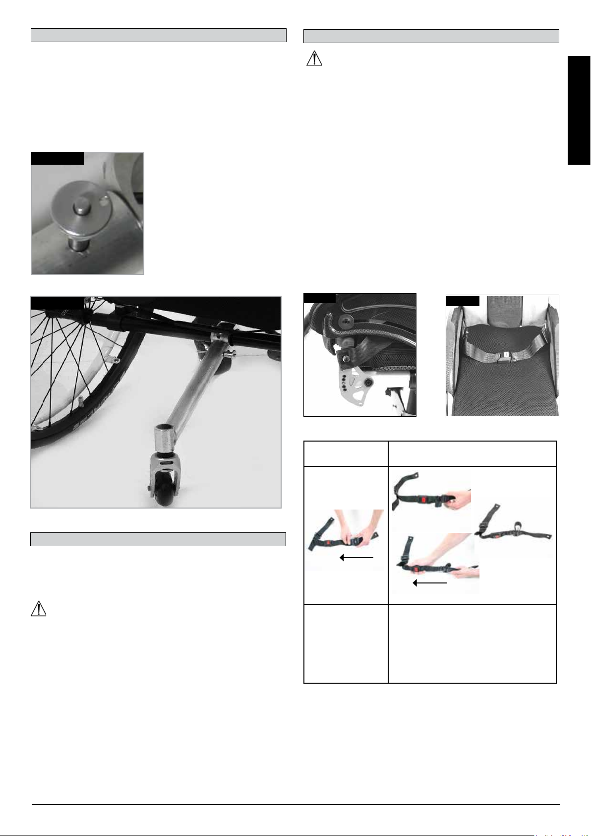
The lap belt is fitted to the wheelchair as shown in the
illustrations. The seat belt comprises 2 halves. They are fitted
using the existing seat stay retaining bolt fitted through the
eyelet on the belt. The belt is routed under the rear of the side
panel. (Fig. 4.36)
Adjust the belt position so buckles are in the centre of the seat.
(Fig. 4.37)
Fig. 4.36
Fig. 4.37
ENGLISH
Crutch Holder
Crutch Holder
This device permits crutches to be transported directly on a
wheelchair. It has a Velcro loop to fasten crutches or other aids.
CAUTION!
Never try to use or even remove the crutches or other aids while
moving.
Adjust lap belt to suit the user’s needs as follows:
To reduce the belt
length
Feed free belt
back through male
buckle and slide
adjusters.
Ensure belt is not
looped at male
buckle.
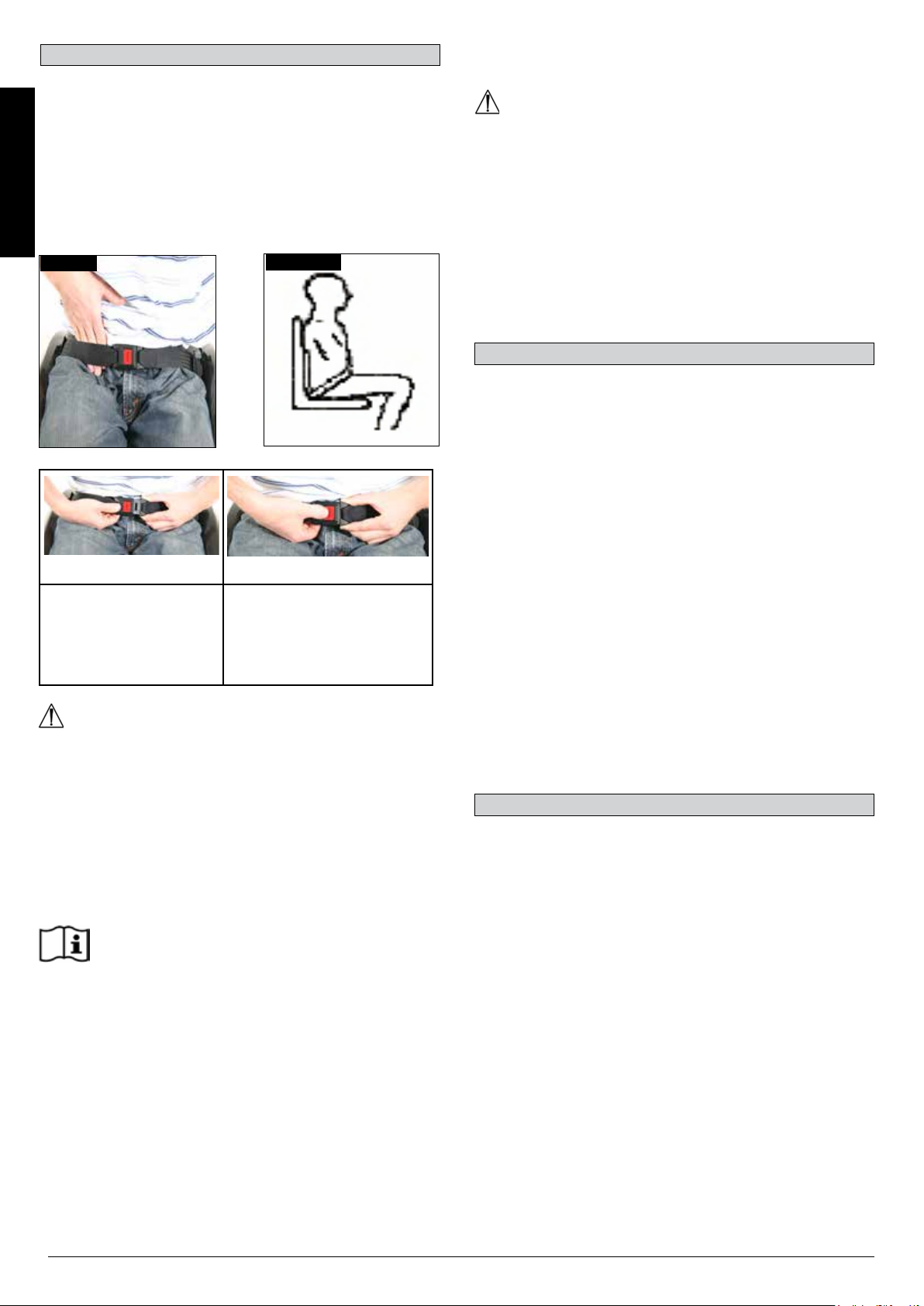
When fastened check space between the pelvic restraint belt
and user. When correctly adjusted it should not be possible to
insert more than the flat of the hand between the lap belt and the
user. (Fig. 4.38)
To increase the belt length
Feed free belt through slide adjusters
and male buckle to provide more belt
length.
Helium Rev.7.0
19
Page 20
Pelvic Restraint Belt...
The lap belt should be fixed so that the belt sits at an angle of 45
degrees across the user’s pelvis. The user should be upright
and be as far back as possible in the seat when correctly
adjusted. The lap belt should not allow the user to slip down in
the seat.
(Fig. 4.39)
ENGLISH
Maintenance:
Check lap belt and securing components at regular intervals for
any sign of fraying or damage. Replace if necessary.
WARNING
The lap belt should be adjusted to suit the end user as detailed
above. Sunrise Medical recommends that the length and fit of
the belt be checked on a regular basis to reduce the risk of the
end user inadvertently re-adjusting the belt to an excessive
length.
Fig. 4.38
To fasten buckle:
Firmly push male buckle
into female buckle.
Fig. 4.39
To release belt:
Press exposed sides of male
buckle and push towards
centre whilst gently pulling
apart.
5.0 Tyres and Mounting
Solid rubber tyres are standard.
With pneumatic tyres always make sure that the tyres have the
correct air pressure, as otherwise the performance of the
wheelchair may be affected. If the tyre pressure is too low, rolling
resistance will increase, requiring more effort to move the chair
forward. Low tyre pressure also has a negative impact on
manoeuverability. If the tyre pressure is too high, the tyre could
burst. The correct pressure for a given tyre is printed on the
surface of the tyre itself.
Tyres can be mounted the same way as an ordinary bicycle tyre.
Before installing a new inner tube, you should always make sure
that the base of the rim and the interior of the tyre are free of
foreign objects. Check the pressure after mounting or repairing a
tyre. It is critical to your safety and to the wheelchair’s
performance that regulation air pressure be maintained and that
tyres are in good condition.
WARNING!
• If in doubt about the use and operation of the lap belt then
ask your healthcare professional, wheelchair dealer, carer
or attendant for assistance.
• If you want to retrofit a lap belt, then please contact your
authorised Sunrise Medical dealer.
• The lap belt must be checked on a daily basis to ensure it
is adjusted correctly and free from any obstruction or
adverse wear.
• Sunrise Medical does not encourage the transportation of
any person in a vehicle using this lap belt as a method of
restraint.
Please see Sunrise Medical transit booklet for further
advice on transportation.
6.0 Maintenance and care
• Check the tyre pressure every 4 weeks. Check all tyres for
wear and damage.
• Check the brakes approximately every 4 weeks to make
sure that they are working properly and are easy to use.
• Change tyres as you would an ordinary bicycle tyre.
• All of the joints that are critical to using your wheelchair
safely are self-locking nuts. Please check every three
months to make sure that all bolts are secure (see the
section on torque). Safety nuts should only be used once
and should be replaced after use.
• Please use only mild household cleansers when your
wheelchair is dirty. Use only soap and water when cleaning
the seat upholstery.
• You should only use genuine parts approved by Sunrise
Medical. Do not use parts from other manufacturers, that
have not been by authorised by Sunrise Medical.
20
Helium Rev.7.0
Page 21

6.0 Maintenance and care...
• If your wheelchair should ever get wet, please dry it afterwards.
• A small amount of sewing-machine oil should be applied to
quick-release axles approximately every 8 weeks. Depending
on the frequency and type of use, we recommend taking your
wheelchair to your authorised dealer every 6 months to have it
inspected by trained personnel.
• If you want to store the wheelchair for a long period of time,
then no further measures are required. Make sure that the
wheelchair is stored at room temperature in a dry place which
is protected from strong sunlight. Before using it again, the
wheelchair should be checked by an authorised dealer.
CAUTION!
Sand and sea water (or salt in the winter) can damage the
bearings of the front and rear wheels. Clean the wheelchair
thoroughly after exposure.
The following parts can be removed and sent back to the
manufacturer/dealer for repair:
• Rear wheels
• Armrest
• Anti-Tip tubes
These components are available as spare parts. For further
information, please see the spare parts catalogue.
Hygiene measures when being re-used:
Prior to the wheelchair being re-used, it must be carefully
prepared. All surfaces which come into contact with the user
must be treated with a disinfection spray.
To do this, you must use a disinfectant from the DGHM list, e.g.
Antifect Liquid (Schülke & Mayr) for rapid alcohol-based
disinfection for medical products and medical devices, which
must be disinfected quickly.
Please pay attention to the manufacturer’s instructions of the
disinfectant you are using.
In general, a complete disinfection cannot be guaranteed on
seams. We therefore recommend that you dispose of seat and
back slings to avoid microbacterial contamination with active
agents according to § 6 infection protection law.
7.0 Disposal / Recycling of Materials
If the wheelchair has been made available to you free of charge,
then it does not belong to you. If it is no longer required, then
follow the instructions to return it as given by the organisation
that made the wheelchair available to you.
In the following section, there is a description of the materials
used on the wheelchair, in view of the disposal or recycling of
the wheelchair and its packaging.
Particular regulations with regard to disposal or recycling may
be in force locally and these must be taken into account when
performing disposal. (This can include the cleaning or
decontamination of the wheelchair prior to disposal).
Aluminium: Castor forks, wheels, sideguards for the chassis,
armrest frame, footrest, push handles
Steel: Fixing points, quick-release axle
Plastic: Handgrips, tube plugs, castor wheels, footplates,
armpads and 12” wheel/tyre
Packaging: Plastic bags made of soft polyethylene, cardboard
Upholstery:Woven polyester with PVC coatings and expanded
combustion modified foam.
Disposal or recycling should be done through a licensed agent
or authorised place of disposal. Alternatively your wheelchair
may be returned to your dealer for disposal.
8.0 Trouble-shooting
Wheelchair pulls to one side
• Check tyre pressure
• Check to make sure wheel turns easily (bearings, axle)
• Check the castor angle
• Check to make sure both castors are making proper contact
with the ground.
Castors begin to wobble
• Check the castor angle
• Check to make sure all bolts are secure; tighten if necessary
(see the section on torque)
• Check to make sure both castors are making proper contact
with the ground.
Wheelchair / Cross-tube assembly does not snap into
position in the seat saddle
• Chair is still new, i.e., the seat or backrest upholstery is still
very stiff. This will improve with time.
Wheelchair is difficult to fold up:
• Adjustable backrest upholstery is too stiff. Loosen it
accordingly.
Wheelchair squeaks and rattles
• Check to make sure all bolts are secure; tighten if necessary
(see the section on torque)
• Apply small amount of lubrication to spots where movable parts
come into contact with one another
Wheelchair begins to wobble
• Check angle at which castors are set
• Check tyre pressure
• Check to see if rear wheels are adjusted differently.
ENGLISH
Helium Rev.7.0
21
Page 22
9.0 Transportation
DANGER!
There is a risk of serious injury or death if this advice is ignored!
Transportation of your wheelchair within a vehicle:
A wheelchair secured in a vehicle will not provide the equivalent
level of safety and security as a vehicle seating system. We
recommend that the user transfers to the vehicle seating. It is
ENGLISH
recognised that this is not always practical for the user to be
transferred and in these circumstances where the user must be
transported whilst in the wheelchair the following advice should
be followed:
DANGER!
• Confirm that your chair is crashtest suitable (see nameplate
or crashtest bracket at the rear of the chair (Fig. I)
• Confirm that the vehicle is suitably equipped to transport a
passenger in a wheelchair, and ensure the method of
access/egress is suitable for your wheelchair type. The
vehicle should have the floor strength to take the combined
weight of the user, the wheelchair and accessories.
• Sufficient space should be available around the wheelchair
to enable clear access to attach, tighten and release the
wheelchair and occupant tie down restraints and safety
belts.
• The occupied wheelchair must be located in a forward
facing position and secured by the wheelchair tie down and
occupant restraint straps (WTORS tie downs meeting the
requirements of ISO 10542 Part 2 or SAE J2249) in
accordance with the WTORS manufacturer’s instructions.
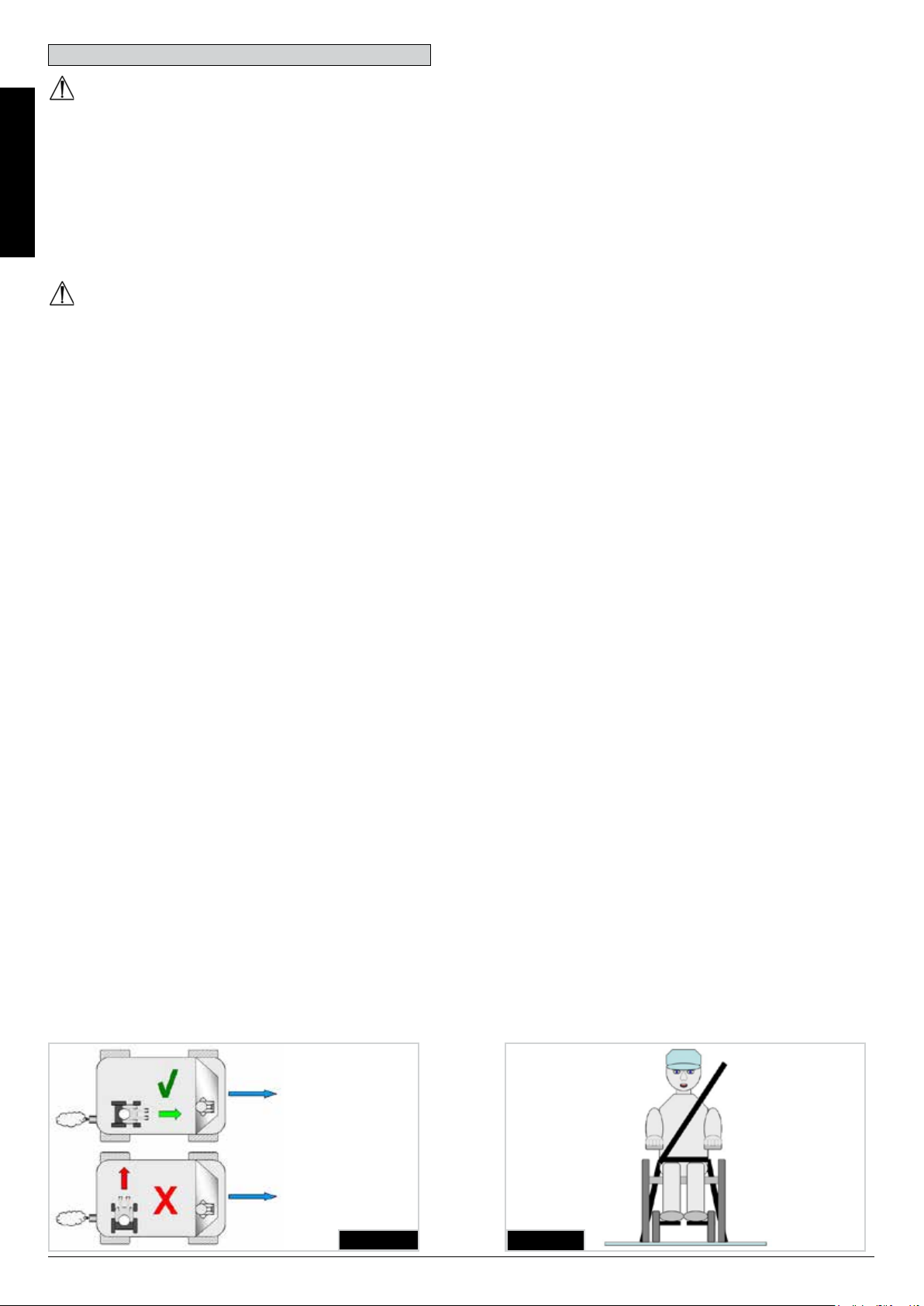
• The wheelchair’s use in other positions within a vehicle has
not been tested e.g. transportation in a side facing position
must not be carried out under any circumstances (Fig. A).
• The wheelchair should be secured by a Tie Down Restraint
system, conforming to ISO 10542 or SAE J2249 with nonadjustable front straps and adjustable rear straps, which
typically use Karabiner clips/S hooks and tongue and
buckle fittings. These restraints generally comprise of 4
individual straps that are attached to each corner of the
wheelchair.
• The tie-down restraints should be fitted to the main frame of
the wheelchair as indicated in the diagram on the following
page, and not to any attachments or accessories, e.g. not
around the spokes of wheels, brakes or footrests.
• The tie–down restraints should be attached as close as
possible at an angle of 45 degrees and tightened securely in
accordance with the manufacturer’s instructions.
• Alterations or substitutions must not be made to the wheelchair
tie down points or to structural and frame or components
without consulting the manufacturer. Failure to do so will
invalidate the ability of a Sunrise Medical wheelchair to be
transported within a vehicle.
• Both pelvic and upper torso restraint belts must be used to
restrain the occupant to reduce the possibility of head and
chest impacts with the vehicle components and serious risk of
injury to the user and other vehicle occupants. (Fig. B) The
upper torso restraint belt should be mounted to the vehicle “B”
pillar - failure to do so will increase the risk of serious
abdominal injuries to the user.
• A head restraint suitable for transportation (see label on
headrest) must be fitted and suitably positioned at all times
during transportation.
• Postural supports (lap straps, lap belts) should not be used or
relied on for occupant restraint in a moving vehicle unless they
are labelled as meeting the requirements specified in ISO
7176-19:2001 or SAE J2249.
• The safety of the user during transportation depends upon the
diligence of the person securing the tie-down restraints and
they should have received appropriate instructions and/or
training in their use.
• Wherever possible remove and stow safely away from the
wheelchair all auxiliary equipment, for example:
• Crutches, Loose cushions and Tray Tables.
• Articulating/elevating legrest should not be used in the elevated
position when the wheelchair and user are being transported
and the wheelchair is restrained using Wheelchair Transport
and Occupant Restraints.
• Reclining backrests should be returned to an upright position.
• The manual brakes must be firmly applied.
• Restraints should be mounted to the vehicle “B” pillar and
should not be held away from the body by wheelchair
components such as armrest or wheels.
22
Fig. A
Fig. B
Helium Rev.7.0
Page 23
Transportation...
Occupant Restraints Instruction:
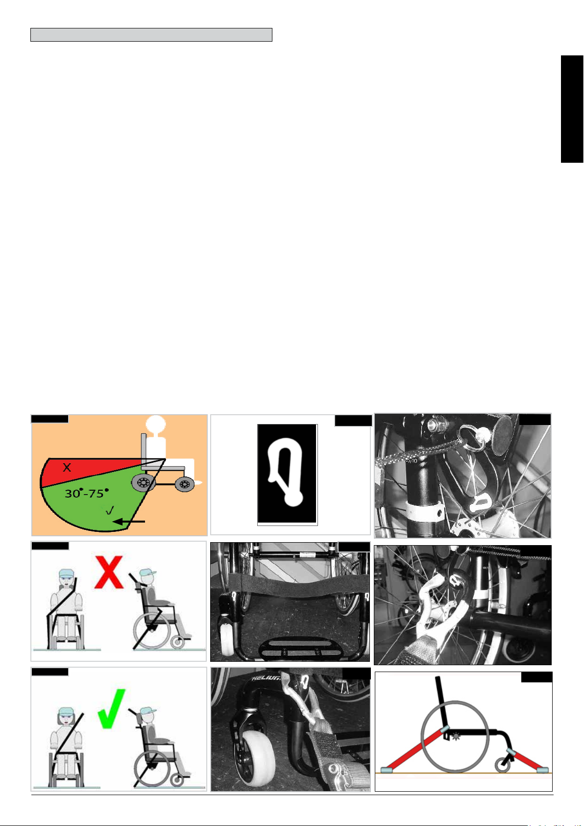
1. The pelvic restraint belt must be worn low across the front of
the pelvis so that the angle of the pelvic belt is within the
preferred zone of 30 to 75 degrees to the horizontal.
A steeper (greater) angle within the preferred zone is desirable
i.e. closer to, but never exceeding 75°. (Fig. C)
2. The upper torso restraint belt must fit over the shoulder and
across the chest as illustrated Fig. D and E.
Restraint belts must be adjusted as tightly as possible
consistent with user comfort.
Restraint belt webbing must not be twisted when in use.
The upper torso restraint belt must fit over the shoulder and
across the shoulder as illustrated in Fig. D and E.
3. The attachment points to the chair are the inner front side
frame just above the castor, and the rear side frame. The straps
are fitted around the side frames at the intersection of the
horizontal and vertical frame tubes. (See Figs G-H-I)
4. The tie down symbol (Fig. F) on the wheelchair frame
indicates the position of the wheelchair restraint straps. The
straps are then tensioned after the front straps have been fitted
to secure the wheelchair.
USER WEIGHT LESS THAN 22 kg
When the user being transported is a child, less than 22 kg mass
and the vehicle involved has less than eight (8) seated passengers
it is recommended that they be transferred to an UNCE Regulation
44 compliant child restraint system (CRS).
This type of restraint system provides a more effective occupant
restraint system than the conventional 3 point occupant restraint
system and some CRS systems also include additional postural
supports to assist in maintaining the position of the child when
seated.
Parents or care providers may consider the option, in some
circumstances, for their child is to remain in their wheelchair whilst
in transport due to the level of posture control and comfort
provided by the set up in the wheelchair.
We would recommend in such circumstances that a risk
assessment be carried out by your attendant and relevant
competent persons.
Positioning of wheelchair tie down restraints on wheelchair:
1. Location of the front and rear tie down labels (Fig. G - H).
2. Position of the front, (Fig. I) and rear, (Fig. J), wheelchair tie
down restraint and the tie down label.
3. Side view of tie down straps, (Fig. K).
ENGLISH
Fig. C
Fig. D
Fig. E
PREFERRED
ZONE
Fig. F
Fig. G
Fig. H
Fig. I
Fig. J
Fig. K
Helium Rev.7.0
23
Page 24
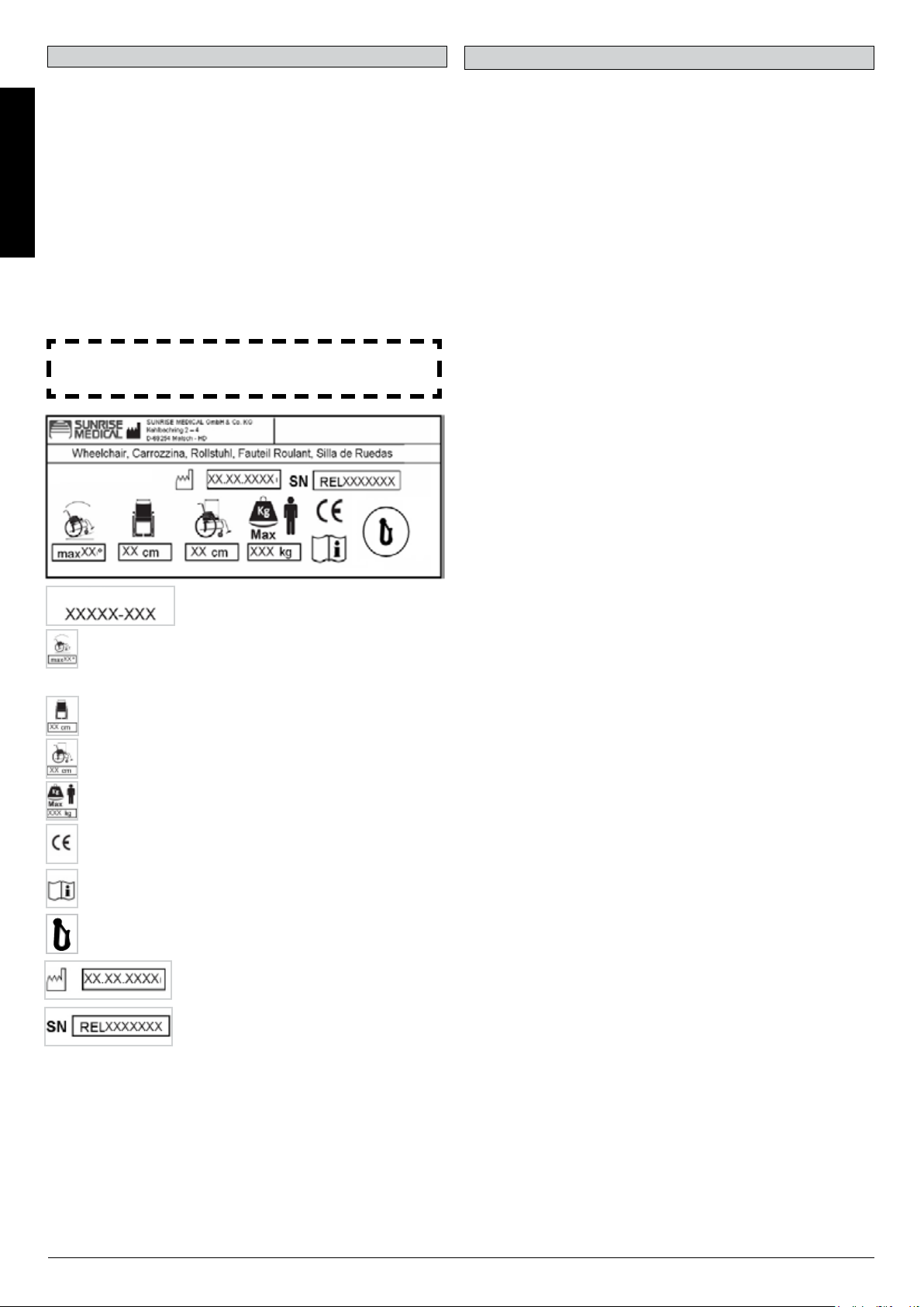
10.0 Nameplate
Name Plate
The nameplate is located on either the cross-tube assembly or
the transverse frame tube, as well as on a label in the owner’s
manual. The nameplate indicates the exact model designation
and other technical specifications. Please provide the following
pieces of information whenever you have to order replacement
parts or to file a claim:
ENGLISH
• Serial number
• Order number
• Month/Year
SAMPLE
Helium
Helium
Product Name/SKU Number.
Maximum safe slope with anti-tip tubes fitted,
Depends on wheelchair setting, posture and
physical capabilities of the user.
Seat width.
Depth (maximum).
Load Maximum.
CE Mark
11.0 Warranty
Warranty
THIS IN NO WAY AFFECTS YOUR STATUTORY RIGHTS.
Warranty conditions
1) Repair or replacement is carried out by the authorised Sunrise
Medical dealer.
2) To fulfil the guarantee conditions, should servicing need to be
carried out on your wheelchair under this agreement, contact the
designated Sunrise Medical customer service agent immediately,
with precise details on the type of difficulty. Should you be using
the wheelchair outside the area covered by the designated Sunrise
Medical customer service agent, the work will be carried out under
"guarantee conditions" by another agency as designated by the
manufacturer.
3) Should any part of the wheelchair require repair or replacement,
as a result of a specific manufacturing or material defect, within 24
months (5 years on frame and cross brace) from the date on which
the possession of the product was transferred to the original
purchaser, and subject to it remaining within that ownership, the
part or parts will be repaired or replaced completely free of charge
if returned to the authorised service agent.
Note: This guarantee is not transferable.
4) The guarantee also covers all repaired or replaced parts for the
remaining period of the guarantee for the wheelchair.
5) For spare parts which are fitted after the start of the original
guarantee, we give a further 24-month guarantee.
6) Consumable parts are normally excluded from the guarantee,
except in the case that premature wear of the part is the direct
result of a manufacturing fault. These parts include, amongst
others, upholstery, tyres, inner tubes and similar parts.
7) The above warranty conditions apply to all product parts for
models purchased at full retail price.
8) Normally we do not accept responsibility if a repair or
replacement of the wheelchair is required for one of the following
reasons:
a) The product or part has not been maintained or serviced in
accordance with the manufacturer's recommendations as shown in
the User Instructions and/or the Service Instructions. Accessories
have been used which are not specified as original accessories.
b) The wheelchair or a part of the wheelchair was damaged
through neglect, accident or improper use.
c) Alterations to the wheelchair or parts, which are not in
accordance with the manufacturer’s specifications or the carrying
out of repairs before informing the customer service agent.
24
User's Guide.
Crash Tested
Date of manufacture.
Serial number.
Helium Rev.7.0
Page 25

12.0 Technical Data
Total width:
With 25" standard wheels, incl. handrims with 6° camber: SW + 300 mm
Overall length: 910 mm with SD 48
Total height: 1120 mm with BH 45
Weight in kg: from 6.4 kg
Maximum load:
Helium 125 kg
Seat heights:
The choice of frames, forks and castors, as well as the rear wheel size (24”, 25”) determines the seat heights which can be achieved.
Norm Min. Max. Norm Min. Max.
Overall length with
footrest
Overall Width 620 mm 760 mm Effective seat depth 340 mm 480 mm
Folded length N/A N/A Effective seat width 320 mm 460 mm
Folded width N/A N/A Seat surface height at
Folded Height N/A N/A Backrest angle 59° 105°
Total Mass 6.4 kg 13.0 kg Backrest height 250 mm 450 mm
Slope for the use of
the wheel locks
Mass of the heaviest
part
Static stability
downhill
Static stability uphill
with anti-tip tubes
Static stability
sideways
Dynamic stability uphill power
consumption
770 mm 1050 mm Seat surface angle 0° 15°
front edge
0° 7° Turning radius 670 mm
- 2.1 kg with
24" rear wheel
*
10° 10° Angle from leg to seat 92° 100°
10° 10° Distance from the
10° 10° Front location of
N/A N/A Handrim diameter 540 mm 567 mm
Distance from the
footrest to the seat
armrest to the seat
armrest structure
430 mm 550 mm
220 mm 520 mm
N/A N/A
N/A N/A
ENGLISH
Overcoming
obstacles
*Standard wheel with stainless steel handrim
The wheelchair conforms to the following standards:
a) Requirements and tests for static strength, impact resistance and fatigue strength (ISO 7176-8) Yes.
b) Drive and control systems for power wheelchairs, requirements and test (ISO 7176-14) n.a.
c) Environmental test in accordance with ISO 7176-9 n.a.
d) Flammability resistance of upholstered parts in accordance with ISO 7176-16 (EN 1021-1/2) Yes.
Helium Rev.7.0
N/A N/A Horizontal location
of axle
+ 56 mm + 11 mm
25
Page 26

Technical Data >>>
Castor Fork Frame Type Front seat height
in mm
430 430 - 300
ENGLISH
low
98 mm x 32 mm
440 440- 310
450 450 - 320
470 470 - 340
high
480 480 - 350
490 490 - 360
3" (76.2 mm)
440 440 - 310
low
450 450 - 320
460 460 - 330
111 mm x 32 mm
480 480 - 350
high
490 490 - 360
500 500 - 370
440 440 - 310
low
450 450 - 320
460 460 - 330
98 mm x 32 mm
480 480 - 350
high
490 490 - 360
500 500 - 370
450 450 - 320
low
460 460 - 330
470 470 - 340
111 mm x 32 mm
490 490 - 360
high
500 500 - 370
510 510 - 380
450 450 - 320
4" (101.6 mm)
low
460 460 - 330
470 470 - 340
111 mm x 45 mm
490 490 - 360
high
500 500 - 370
510 510 - 380
450 450 - 320
460 460 - 330
low
470 470 - 340
480 480 - 350
123 mm x 45 mm
490 490 - 360
500 500 - 370
high
510 510 - 380
520 520 - 370
Rear seat height
in mm
26
Helium Rev.7.0
Page 27

Technical Data ...
Castor Fork Frame Type Front seat height
in mm
460 460 - 330
low
470 470 - 340
98 mm x 32 mm
500 500 - 370
high
510 510 - 380
460 460 - 330
low
470 470 - 340
480 480 - 350
111 mm x 32 mm
500 500 - 370
high
510 510 - 380
520 520 - 390
470 470 - 340
5" (127 mm)
low
480 480 - 350
111 mm x 45 mm
high 510 510 - 380
520 520 - 390
470 470 - 340
480 480 - 350
low
490 490 - 360
500 500 - 370
123 mm x 45 mm
510 510 - 380
520 520 - 390
high
530 530 - 400
540 540 - 410
500 500 - 370
low
510 510 - 380
6" (152.4 mm) 123 mm x 45 mm
540 540 - 410
high
550 550 - 420
Rear seat height
in mm
ENGLISH
Helium Rev.7.0
27
Page 28

13.0 Torque
ENGLISH
Torque.
20 Nm
20 Nm
NOTE: Wherever torque settings are specified, it is strongly recommended that a torque meter (not included), is used to verify correct
torque specification is achieved.
If no other information is given, the generic torque for M6 screws is 7 Nm.
CAUTION: Some of the screws that are used during manufacture are fitted with threadlock, (blue dot on the thread) and can be undone
and re-tightened up to three times before they must be replaced with new screws and threadlock. Alternatively, you can put Loctite™
243 threadlock on the screws and re-fit them.
28
Helium Rev.7.0
Page 29

Sommaire
Définitions
Sommaire 29
Définitions 29
Avant-propos 30
Utilisation 30
Champ d'application. 30
1.0 Consignes générales de sécurité et
limites de conduite 31
2.0 Manipulation 33
3.0 Transport du fauteuil 33
4.0 Options 33
Leviers de basculement 33
Freins 33
Mécanisme de suspension 35
Réglage du support d'axe pour handbike 36
Réglage du centre de gravité de l'Helium 37
Réglage du centre de gravité de l'Helium Pro 37
Réglage de la palette 38
Siège 38
Options - Snoll on 38
Roues avant 39
Alignement des roues 39
Dossier 40
Protège-vêtements 42
Poignée de poussée 43
Roulettes anti-bascule 43
Porte-canne 44
Ceinture pelvienne 44
5.0 Pneus et montage des pneus 45
6.0 Maintenance et entretien 45
7.0 Mise au rebut / Recyclage des matériaux 46
8.0 Dépannage 46
9.0 Transport 47
10.0 Plaque signalétique 49
11.0 Garantie 49
12.0 Caractéristiques techniques 50
13.0 Couple réel 53
3.1 Dénitions des termes employés dans le manuel
Terme Définition
Indication d'un risque
potentiel de blessures
DANGER !
AVERTISSEMENT !
ATTENTION !
REMARQUE :
sérieuses ou de mort en
cas de non-respect des
consignes
Indication d'un risque de
blessure en cas de nonrespect des consignes
Indication que le matériel
peut être endommagé si le
conseil fourni n'est pas suivi
Conseil d'ordre général ou
pratique recommandée
Référence faite à d'autres
manuels
FRANÇAIS
REMARQUE :
Il est possible que les fauteuils illustrés et décrits dans le
présent manuel ne soient pas complètement identiques au
modèle que vous avez acheté. Toutefois, toutes les instructions
fournies dans le présent manuel sont valables pour votre
matériel, malgré d'éventuelles différences minimes.
Le fabricant se réserve le droit de modifier sans préavis les
poids, mesures et autres données techniques indiquées dans
le présent manuel. Tous les chiffres, dimensions et capacités
indiqués dans ce manuel sont approximatifs et ne constituent
pas des caractéristiques.
Helium Rev.7.0
REMARQUE :
Il vous est conseillé de noter dans l’encadré prévu ci-dessous
les coordonnées du technicien chargé de votre service aprèsvente.
En cas de panne, contactez-le en lui donnant le plus
d’informations possible sur la nature de la panne pour qu’il
puisse vous aider efficacement et rapidement.
Tampon et signature du revendeur
29
Page 30

Avant-propos
Utilisation
Chère cliente, cher client,
Vous avez choisi un produit de SUNRISE MEDICAL de grande
qualité. Nous nous en réjouissons.
Ce manuel d’utilisation vous fournira de nombreux conseils et
suggestions de sorte que votre produit deviendra pour vous un
partenaire familier digne de confiance.
Pour Sunrise Medical, être proche de nos clients est une
priorité. C’est pourquoi, nous tenons à vous tenir informé de
FRANÇAIS
toutes nos nouveautés, actuelles et à venir. Etre proche de nos
clients signifie, assurer un service rapide, avec le moins de
formalités administratives possible et entretenir une bonne
relation avec eux. Que vous souhaitiez commander des pièces
de rechange ou des accessoires, ou encore poser des
questions concernant votre fauteuil, nous sommes à votre
service.
Notre objectif est que vous soyez satisfait de nos services.
Chez Sunrise Medical, nous travaillons en permanence au
développement de nos produits. Ainsi, des modifications quant
à la forme, à la technique et à l’équipement peuvent être
apportées à notre gamme de produits. Aucune réclamation ne
pourra donc être adressée au sujet des informations et
illustrations de ce manuel d’utilisation.
Le système de gestion de SUNRISE MEDICAL est certifié
EN ISO 9001, ISO 13485 et ISO 14001.
En sa qualité de fabricant, SUNRISE MEDICAL,
déclare que les fauteuils sont conformes à la
directive 93/42/CEE telle que modifiée par
2007/47/CEE.
Adressez-vous à notre service après-vente SUNRISE
MEDICAL, compétent et agréé, pour toute question concernant
l’utilisation, la maintenance ou la sécurité de votre fauteuil
roulant.
S’il n’y a aucun revendeur près de chez vous
ou si vous avez des questions relatives à la sécurité des
produits et des rappels de produits, contactez Sunrise Medical
par écrit ou par téléphone, ou rendez-vous sur www.
sunrisemedical.co.uk
Les fauteuils roulants sont exclusivement destinés aux
utilisateurs dans l'incapacité de marcher ou à mobilité restreinte
et pour leur propre usage, qu'ils soient capables de faire
avancer leur fauteuil seuls ou qu'ils soient poussés par une
tierce personne (un accompagnateur), à leur domicile et à
l'extérieur.
La charge maximale (à savoir le poids de l'utilisateur et des
accessoires éventuellement embarqués) est indiquée sur la
plaque signalétique apposée sur le tube d'axe, sous le
siège.
La garantie n'est valable que si le produit est utilisé dans les
conditions spécifiées et pour l'usage pour lequel il est prévu.
La durée de vie prévue pour ce fauteuil est de cinq années.
N'utilisez ET n'installez aucun composant tiers sur le fauteuil, à
moins qu'ils n'aient été formellement approuvés par Sunrise
Medical.
Champ d'application.
De par la diversité des options de montage et sa conception
modulaire, ce fauteuil convient pour les personnes dans
l'incapacité de marcher ou à mobilité restreinte, suite à :
• Une paralysie
• La perte d'un membre (amputation de la jambe)
• Un problème/la difformité d'un membre
• Des contractures/blessures aux articulations
• Maladie, telle qu'une insuffisance cardiaque et circulatoire,
trouble de l'équilibre ou cachexie, ainsi que pour les personnes
âgées ayant assez de force dans le haut du corps.
Sélectionner le bon fauteuil nécessite de prendre en compte des
éléments tels que la taille de l'utilisateur, son poids, sa
constitution physique et psychologique, son âge, son mode de
vie et son environnement.
IMPORTANT :
N'UTILISEZ PAS VOTRE FAUTEUIL AVANT
D'AVOIR LU ET COMPRIS CE MANUEL.
Sunrise Medical S.A.S
ZAC de la Vrillonnerie
17 Rue Mickaël Faraday
37170 Chambray-Lès-Tours
Tel : + 33 (0) 247554400
Fax : +30 (0) 247554403
www.sunrisemedical.fr
30
Helium Rev.7.0
Page 31

1.0 Consignes générales de sécurité et limites de conduite
• Pour éviter les chutes et situations dangereuses, il est
• Pour monter et descendre du fauteuil, ne prenez pas appui
• Utilisez toujours votre fauteuil de manière adéquate. Evitez
• Les freins d'immobilisation ne servent pas à ralentir le
• Changer le centre de gravité peut avoir un impact sur le
• Avec des réglages extrêmes (comme les roues arrière en
• Lorsque vous franchissez des côtes et des marches,
La conception et la construction du fauteuil sont réalisées pour
garantir une sécurité maximale. A l'échelle internationale, toutes
les exigences applicables en matière de normes de sécurité
sont respectées, voire dépassées. Toutefois, l’utilisateur peut se
mettre en situation de danger en utilisant son fauteuil de façon
incorrecte. Pour votre sécurité, vous devrez impérativement
respecter les consignes suivantes.
Les altérations ou réglages non professionnels ou erronés
augmentent le risque d'accidents. En tant qu’utilisateur de
fauteuil roulant, vous participez à la circulation publique, sur
routes ou trottoirs. Vous êtes par conséquent tenu de respecter
le code de la route.
Lors de votre première utilisation du fauteuil, roulez
prudemment. Familiarisez-vous avec l'utilisation de votre
nouveau fauteuil roulant.
Avant chaque utilisation de votre fauteuil, contrôlez
impérativement :
• Les axes à déverrouillage rapide des roues arrière
• Le Velcro du siège et des accoudoirs
• Les pneus, la pression et les freins.
Avant de modifier un quelconque réglage, il est important de lire
le paragraphe correspondant du présent manuel d'utilisation.
Des nids de poule ou un sol irrégulier peuvent faire basculer le
fauteuil roulant lors de la montée ou de la descente des pentes.
Si une marche ou une pente est abordée de face, le corps doit
être incliné vers l'avant.
DANGER !
• Ne dépassez JAMAIS la charge maximale de 125 kg
combinée entre l'utilisateur et tout autre accessoire
éventuellement embarqué. Veuillez noter les informations
relatives au poids pour les options plus légères, lesquelles
sont indiquées séparément. Toute charge supérieure
pourrait endommager le fauteuil ou vous faire basculer,
perdre le contrôle et entraîner de graves blessures pour
vous et toute autre personne.
• Dans la pénombre, portez des vêtements clairs ou
réfléchissants de sorte à être vu par les autres usagers de
la route. Veillez à ce que les réflecteurs latéraux et arrière
du fauteuil restent bien visibles. Il est également
recommandé d'installer une lumière.
• Lorsque vous descendez des côtes et des marches,
• Evitez d'utiliser les escalators. En cas de chute, vous
• N'utilisez pas le fauteuil sur des pentes de plus de 10°
• Des nids de poule ou un sol irrégulier peuvent faire
• N'utilisez pas le fauteuil sur des terrains boueux ou
• Pour éviter de vous blesser aux mains, ne placez pas vos
• Si vous utilisez une main courante métallique et freinez
• Monter ou descendre une pente latéralement augment le
• Ne montez et descendez les escaliers que si vous êtes
recommandé de vous entraîner et de vous familiariser avec
votre nouveau fauteuil sur une surface plane offrant une
bonne visibilité.
sur les palettes. Il convient au contraire de les rabattre et
de les pivoter vers l'extérieur le plus possible. Placez-vous
toujours le plus près possible de l'endroit où vous voulez
vous asseoir.
par exemple de franchir des obstacles sans avoir
préalablement ralenti (marche, bord de trottoir).
fauteuil. Ils empêchent votre fauteuil d'avancer
involontairement. Quand vous vous tenez sur un terrain
accidenté, utilisez impérativement vos freins
d’immobilisation. Pensez toujours à actionner les deux
freins simultanément, autrement votre fauteuil pourrait
basculer.
comportement du fauteuil dont vous devez être conscient.
Il est recommandé de vous entraîner, par exemple en
pente ou lors du franchissement d'obstacles. Familiarisezvous avec les différents comportements en présence d'un
accompagnateur.
position la plus avancée possible) et une posture
inadéquate, le fauteuil risque de basculer, même sur une
surface plane.
penchez votre corps plus en avant.
penchez votre corps plus en arrière. Ne tentez jamais de
monter ou de descendre une pente en diagonal.
pourriez vous blesser gravement.
d'inclinaison. Le degré d'inclinaison maximum des pentes
dépend de la configuration du fauteuil, des capacités de
l'utilisateur et du style de conduite. Les capacités de
l'utilisateur et son style de conduite ne pouvant être
prédéfinis, le degré d'inclinaison maximum des pentes ne
peut être déterminé. Il revient donc à l'utilisateur, assisté de
son accompagnateur, de déterminer l'inclinaison maximale
afin d'éviter tout risque de basculement. Il est vivement
recommandé d'installer des roulettes anti-bascule pour les
utilisateurs inexpérimentés.
basculer le fauteuil roulant lors de la montée ou de la
descente des pentes.
verglacés. N'utilisez pas le fauteuil dans des zones
interdites aux piétons.
doigts entre les rayons ou entre la roue arrière et le frein de
la roue lorsque le fauteuil est en déplacement.
dans une longue pente ou pour réduire votre allure, le
frottement peut chauffer la main courante et vous brûler les
doigts.
risque de voir le fauteuil basculer sur le côté.
accompagné. Des équipements à cet effet sont à votre
disposition, comme les rampes d'accès et les ascenseurs.
Utilisez-les. En l'absence de tels équipements, deux
personnes sont nécessaires pour faire basculer le fauteuil
et lui faire franchir les marches une à une en le poussant,
et non pas en le soulevant. Il est déconseillé de procéder à
de telles manœuvres dans les escaliers avec des
utilisateurs de plus de 100 kg.
FRANÇAIS
Helium Rev.7.0
31
Page 32

• En général, en présence de roulettes anti-bascule, il
convient de les régler de sorte qu'elles ne puissent heurter
les marches, car cela pourrait entraîner une grave chute.
Replacez ensuite les roulettes anti-bascule à leur position
normale.
• L'accompagnateur doit toujours tenir le fauteuil par les
parties fixes et non pas par les parties amovibles, comme
le repose-pied ou la protection latérale.
• Ce fauteuil n'est pas prévu pour être utilisé pendant des
séances de musculation et/ou l'utilisation d'haltères.
Utilisez uniquement du matériel prévu à cet effet.
• Ne soulevez pas le fauteuil en l'attrapant par les tubes du
FRANÇAIS
dossier, ni par les poignées.
• Lors de l'utilisation d'une rampe d'accès, pensez à
positionner les roulettes anti-bascule (le cas échéant) en
dehors de la zone à risque.
• Immobilisez toujours votre fauteuil à l'aide des freins
lorsqu'il se trouve sur les surfaces accidentées ou lorsque
vous montez dessus ou en descendez.
• Dans la mesure du possible, au cours d'un déplacement à
bord d'un véhicule pour personnes handicapées, il est
conseillé aux occupants de s'asseoir sur les sièges et
d'utiliser le système de retenue approprié. C'est le seul
moyen d'assurer une protection optimale aux occupants en
cas d'accident. Si vous utilisez des éléments de sécurité
proposés par SUNRISE MEDICAL et un système de
sécurité spécifique, les fauteuils légers peuvent servir de
siège pour le déplacement à bord d'un véhicule
spécialement adapté. (Voir le chapitre sur "Transport").
• Selon le diamètre et le réglage des roues avant, ainsi que
le centre de gravité du fauteuil, les roues avant peuvent se
mettre à vibrer à mesure que la vitesse du fauteuil
augmente. Les roues avant risquent alors de se bloquer et
le fauteuil de basculer. Il est donc essentiel de régler
correctement les roues avant (voir le chapitre "Roues
avant"). Ne descendez pas une pente sans frein et
déplacez-vous lentement. Il est recommandé aux
utilisateurs inexpérimentés d'utiliser des roulettes antibascule.
• Les roulettes anti-bascule empêchent le fauteuil de
basculer accidentellement vers l'arrière. En aucun cas,
elles ne doivent remplacer les roulettes de transit et servir
au transport d'une personne dans un fauteuil dont les
roues arrière auraient été retirées.
• Si vous souhaitez atteindre un objet (placé devant, derrière
ou latéralement par rapport au fauteuil), évitez de trop vous
pencher afin de ne pas modifier le centre de gravité et
risquer de faire basculer le fauteuil. La présence d'une
charge supplémentaire (sac à dos ou objets similaires) sur
les montants arrière du dossier peut avoir un impact sur la
stabilité de votre fauteuil (surtout si le dossier est incliné en
arrière) et peut faire basculer le fauteuil en arrière et
entraîner des blessures.
• Les réglages de votre fauteuil, et plus particulièrement les
réglages des composants relatifs à la sécurité, doivent être
réalisés exclusivement par un revendeur agréé. Cette
exigence concerne les freins d'immobilisation, les roulettes
anti-bascule, l'angle d'inclinaison et la hauteur du dossier,
la longueur de jambe inférieure, le centre de gravité, la
ceinture sous-abdominale, le pincement et le carrossage
des roues arrière, la hauteur du siège, ainsi que le
pincement et la stabilité directionnelle de la fourche.
• Lors de l'utilisation d'accessoires de mobilité montés sur le
fauteuil roulant, comme le handbike, la fonction assistée,
etc., vérifiez que votre fauteuil est équipé des fourches
appropriées à cet usage. N'hésitez pas à contacter votre
revendeur en cas de doute.
• N'équipez le fauteuil d'aucun dispositif électronique,
dispositif de mobilité électrique ou mécanique, vélo à main
ou tout autre dispositif non approuvé susceptible de
modifier l'usage prévu du fauteuil ou sa structure.
• L'ajout de dispositifs médicaux supplémentaires nécessite
l'approbation de Sunrise Medical.
• À noter que dans certaines configurations, le fauteuil peut
dépasser la largeur de 700 mm. Si tel est le cas, certaines
issues de secours peuvent ne pas permettre le passage du
fauteuil. Par ailleurs, le déplacement à bord des transports
publics peut être difficile, voire impossible.
• Pour les personnes amputées d'un ou des membres
inférieurs, il est impératif d'utiliser les roulettes anti-bascule.
• Avant d’utiliser votre fauteuil, vérifiez la pression des
pneus. Pour les roues arrière, la pression doit être au
moins de 3,5 bars (350 kPa). La pression maximale est
indiquée sur la jante des pneus. Le frein à manette à
hauteur du genou ne fonctionne que si la pression des
pneus est suffisante et si le réglage est correct (voir le
chapitre sur les "Freins").
• Si les toiles du dossier et du siège sont abîmées,
remplacez-les immédiatement.
• Soyez très vigilants avec les risques d'incendie, surtout
avec les cigarettes allumées. Les toiles du dossier et du
siège peuvent prendre feu.
• Si le fauteuil est exposé au soleil pendant une période
prolongée, certaines parties du fauteuil (par ex. le châssis,
les repose-jambes, les freins et le protège-vêtement)
peuvent chauffer (>41°C).
• Vérifiez que les axes à déverrouillage rapide des roues
arrière sont bien réglés et verrouillés. Si le bouton de l'axe
à déverrouillage rapide n'est pas enfoncé, vous ne pouvez
pas enlever la roue arrière.
AVERTISSEMENT !
• L'efficacité du frein à manette au genou et des
caractéristiques de conduite générales dépend de la
pression des pneus. Le fauteuil sera considérablement plus
léger et plus facile à manœuvrer si les pneus des roues
arrière sont correctement gonflés et ont la même pression.
• Vérifiez la sculpture des pneus. N'oubliez pas que lorsque
vous vous déplacez au milieu de la circulation, vous devez
respecter toutes les réglementations relatives au code de
la route.
• Faites attention de ne pas vous pincer les doigts lorsque
vous procédez à des réglages du fauteuil.
AVERTISSEMENT !
RISQUE D'ÉTOUFFEMENT – Cette aide à la mobilité est
composé de petites pièces qui, dans certaines conditions,
peuvent présenter un risque d'étouffement pour les jeunes
enfants.
Il est possible que les fauteuils illustrés et décrits dans le
présent manuel ne soient pas complètement identiques au
modèle que vous avez acheté. Toutefois, toutes les instructions
fournies dans le présent manuel sont valables pour votre
matériel, malgré d'éventuelles différences minimes.
Le fabricant se réserve le droit de modifier sans préavis les
poids, mesures et autres données techniques indiquées dans le
présent manuel. Tous les chiffres, dimensions et capacités
indiqués dans ce manuel sont approximatifs et ne constituent
pas des caractéristiques.
Sunrise Medical est certifié ISO 9001, garantie d’une qualité
irréprochable à toutes les étapes du développement et de la
fabrication de ses produits. Ce produit est conforme aux
exigences des directives CE. Options ou accessoires
représentés disponibles avec un supplément de prix.
32
Helium Rev.7.0
Page 33

2.0 Manipulation
Axes à déverrouillage rapide de
la roue arrière
Les roues arrière doivent être
munies d'axe à déverrouillage
rapide.
Les roues peuvent être démontées
ou montées sans outils.
Pour démonter les roues, pressez
sur le bouton d'arrêt (1) et retirez la
roue arrière (Fig. 2.1).
ATTENTION !
Lors du montage, appuyez sur le bouton de l'axe à
déverrouillage rapide et insérer l'axe dans le canon, tout en
conservant le bouton pressé. Relâchez le bouton et la roue est
bloquée. Le bouton d'arrêt doit revenir dans sa position de
départ.
Fig. 2.1
1
3.0 Transport du fauteuil
Transport du fauteuil
Les roues arrière sont démontables pour obtenir un fauteuil
aussi compact que possible. Le dossier se rabat en tirant sur la
corde (1) (voir image 3.2) située sur le dossier (Fig. 3.1 et 3.2).
Vous asseoir dans votre fauteuil par vous-même
• Poussez le fauteuil roulant contre un mur ou contre un meuble
solide ;
• Serrez les freins
• L'utilisateur peut s'installer dans le fauteuil
• Puis positionnez les pieds devant les sangles talonnières.
(Fig. 4.1).
Sortir de votre fauteuil par vous-même
• Serrez les freins
• La personne doit se pencher légèrement vers l'avant en se
tenant d'une main sur la roue ou le garde-boue afin de
transférer le poids de son corps vers l'avant du siège, puis
levez-vous en poussant avec les deux pieds par terre, un pied
derrière l'autre (Fig. 4.2).
Fig. 4.1
Fig. 4.2
FRANÇAIS
Fig. 3.1
Dans cette configuration, il est possible de soulever le fauteuil
en l'attrapant par les montants du châssis et la toile d'assise.
Lorsque le fauteuil est transporté inoccupé à bord d'un véhicule
motorisé, il convient de l'arrimer ou de l'attacher.
Fig. 3.2
1
4.0 Options
Leviers de basculement
Leviers de basculement
Le levier de basculement permet à l'accompagnateur(-trice) de
faire basculer le fauteuil pour franchir un obstacle. Placez votre
pied sur le tube d’appui pour faire franchir au fauteuil un trottoir
ou une marche, par exemple.
AVERTISSEMENT !
Freins
Fig. 4.3
ATTENTION !
La puissance de freinage peut être
affectée par un mauvais montage ou
réglage des freins, ainsi que par une pression trop faible des
pneus.
Freins
Le fauteuil est équipé de deux freins d’immobilisation. Les freins
agissent directement sur les pneus. Pour immobiliser votre
fauteuil, abaissez les deux leviers de freinage jusqu'à la butée
avant. Tirez le levier de freinage en arrière pour le relâcher.
Fig. 4.4
3,0 mm
Sunrise Medical recommande vivement l'installation d'un levier
arrière de basculement sur les fauteuils où l'accompagnateur
sera l'utilisateur principal. En l'absence de levier arrière de
basculement, l'utilisation répétée du dossier et la force exercée
dessus pour incliner le fauteuil aura pour effet d'endommager
les montants du dossier.
Helium Rev.7.0
L'effet de freinage diminue quand :
• Les pneus sont usés
• La pression des pneus est trop faible
• Les pneus sont mouillés
•Les freins sont mal réglés.
33
Page 34

Freins...
Les freins d’immobilisation ne sont pas destinés à être utilisés
comme des freins de service. N'actionnez pas les freins en
marche. Freinez toujours à l'aide des mains courantes. Vérifiez
que l’écart entre les pneus et les freins d’immobilisation est
conforme aux valeurs spécifiées. Pour régler, dévissez la vis et
réglez le bon intervalle. Resserrez de nouveau la vis (Fig. 4.3 et
4.4).
ATTENTION !
Vérifiez le réglage des freins après chaque modification de la
FRANÇAIS
position de la roue arrière et refaites votre réglage, si
nécessaire.
Rallonge du levier de frein
La rallonge vous permet de déployer moins d’efforts pour
actionner les freins.
La rallonge est directement vissée aux freins. En le levant, le
levier pourra être rabattu vers l'avant (Fig. 4.5).
ATTENTION !
Plus les freins seront montés près de la roue, plus l’effort à
fournir pour les actionner sera grand. Cela pourrait casser la
rallonge du levier de frein !
Frein unilatéral
Le frein unilatéral se trouve sous la toile d'assise. Pour l'activer,
il suffit de tirer le levier de frein (situé à droite ou à gauche) vers
l'arrière, en direction du pneu. Pour que le frein fonctionne
correctement, il convient de le tirer à fond, jusqu'à ce qu'il
heurte la butée (Fig. 4.6.1).
Réglage
Pour régler le frein, desserrez les vis (1) et placez le frein à
l'endroit où il pourra fonctionner de manière optimale (Fig.
4.6.2).
ATTENTION !
Le montage incorrect du frein unilatéral peut entraîner de
graves blessures pour l'utilisateur et toute autre personne.
Fig. 4.6.1
Veillez à ne pas prendre appui sur la rallonge du levier lorsque
vous montez ou descendez du fauteuil, car vous risqueriez de la
casser ! L’eau projetée par les pneus peut réduire l’efficacité des
freins d’immobilisation.
ATTENTION !
Si le frein n'est pas correctement monté, vous devrez forcer
pour l'actionner.
Cela pourrait casser la rallonge du levier de frein.
Freins compacts
Les freins compacts se trouvent sous la toile du siège. Pour les
activer, il suffit de tirer les freins vers l'arrière, en direction du
pneu. Pour que les freins fonctionnent correctement, il convient
de les tirer jusqu'à ce qu'ils heurtent la butée, (Fig. 4.6).
ATTENTION !
Les vis de montage des freins ne doivent pas être desserrées
et/ou resserrées.
Fig. 4.5
Fig. 4.6
Fig. 4.6.2
1
34
Helium Rev.7.0
Page 35

Mécanisme de suspension
ATTENTION !
AVERTISSEMENT !
La suspension arrière peut avoir un impact sur la stabilité du
fauteuil. Pour éviter de basculer, utilisez un contrôleur et/ou des
roulettes anti-bascule une fois que vous êtes familiarisé avec
votre nouveau fauteuil.
1. Réglage de la suspension arrière 4-Link
a. pour durcir la suspension, tournez l'ajusteur de pré-charge de
ressort (E) dans le sens horaire (si vous regardez le système
de suspension par dessous).
b. pour assouplir la suspension, tournez l'ajusteur de pré-charge
de ressort (E) dans le sens anti-horaire (si vous regardez le
système de suspension par dessous).
2. Alignement des bras de liaison de suspension
Ne modifiez pas l'alignement des bras de liaison (F), (Fig. 4.10).
Les bras sont réglés à l'usine pour garantir un bon alignement et
une bonne performance du système de suspension arrière
4-Link.
(Veuillez-vous référer à la page suivante).
Réglage du pincement et de l’ouverture à zéro (à l'aide de
l'ajusteur installé en usine).
Desserrez les vis hexagonales (G) (2 de chaque côté), qui
maintiennent le support d’axe en place. Observez la bille de
l'ajusteur transparent au centre du support d'axe, puis tournez le
tube d'essieu (C) jusqu'à ce que la bille soit parfaitement
centrée au point le plus bas de l'ajusteur. Le pincement est
maintenant réglé sur zéro (Fig. 4.7, 4.10).
Lorsque vous réglez la suspension arrière 4-Link, procédez à un
seul réglage à la fois et prenez note de chaque changement
apporté. Cela requiert de la patience mais vous permet de
comprendre l'impact de chaque changement sur le déplacement
du fauteuil.
REMARQUE – L'amortisseur de vibrations bas résulte en des
sensations plus souples et permet une bonne course des
suspensions.
ATTENTION !
En aucun cas vous ne devez desserrer la connexion à vis entre le
collier du moyeu et l'amortisseur.
3. Entretien
Les consignes de maintenance énoncées ci-dessous doivent être
respectées, tout comme les instructions relatives à l'entretien
général du fauteuil indiquées à la Section 6.0
a. ne lubrifiez pas les bagues, ni les serpentins.
b. vous pouvez apposer du lubrifiant sur les extrémités de liaison
après avoir nettoyé au savon doux et avec une
brosse à poils souples.
c. utilisez une brosse à poils souples pour enlever les saletés ou
débris du système de serpentin.
d. n'utilisez jamais d'appareil haute pression pour nettoyer la
suspension arrière 4-Link.
FRANÇAIS
Avant de resserrer les vis (G), vérifiez que
les surfaces plates de l'adaptateur de carrossage du support
d'axe dépassent (en saillie) la fixation du support d’axe.
L'extrémité du tube de l'adaptateur de carrossage cylindrique
doit arriver à ras de l'extrémité du support d’axe. Serrez les vis
au couple de 7 Nm.
Réglage du pincement et de l’ouverture à zéro (à l'aide
d'une jauge de réglage à 90°).
Posez le fauteuil sur une table
plate horizontale ou au sol. Dévissez les vis hexagonales (G) (2
de chaque côté) qui maintiennent le support d’axe en place.
Placez ensuite la jauge d'ajustage à un angle de 90°
précisément (utilisez par ex. une équerre) sur les surfaces
plates de l'adaptateur de carrossage (D) (Fig. 4.8, Fig. 4.9).
Tournez le support d’axe jusqu'à ce que les surfaces de la clé
soient parfaitement parallèles à la surface supérieure de la
jauge d'ajustage (Fig. 4.8).
Avant de resserrer les vis (G), vérifiez que
les surfaces plates de l'adaptateur de carrossage du support
d'axe dépassent (en saillie) la fixation du support d’axe.
L'extrémité du tube de l'adaptateur de carrossage cylindrique
doit arriver à ras de l'extrémité du support d’axe. Serrez les vis
au couple de 7 Nm.
C
BALLE
Fig. 4.7
Fig. 4.9
Fig. 4.8
D
B
Fig. 4.10
C
Helium Rev.7.0
D
F
E
35
PARALLÈLE
H
I
G
Page 36

Réglage du support d'axe pour handbike
Support d'axe pour handbike
Il est nécessaire de régler le support d'axe du handbike afin de
déplacer le centre de gravité vers l'arrière. Cela permet une
utilisation sûre de l'accessoire (Fig. 4.10.1).
DANGER !
Utiliser le handbike sans le support d'axe pour handbike a pour
effet de déstabiliser le fauteuil et peut entraîner de graves
blessures pour l'utilisateur et toute autre personne.
FRANÇAIS
Fig. 4.10.1
Fig. 4.10.2
Fig. 4.10.3
Kit de renforcement pour handbike
Pour monter le kit de renforcement pour handbike :
• Insérez le bouton à une extrémité du câble dans le
récepteur à l'avant du châssis (Fig. 4.10.2).
• Insérez le bouton de l'autre extrémité du câble dans le
récepteur à l'arrière du châssis (Fig. 4.10.3).
• Insérez le tendeur (A) dans le récepteur de câble à
l'arrière du châssis (Fig. 4.10.4).
• Tournez le tendeur (A) vers le haut jusqu'à ce que le
récepteur et le montant avant (B) commencent à tirer vers
l'arrière (Fig. 4.10.5).
• Maintenez le câble tendu à l'aide du tendeur et serrez la
vis du récepteur de câble arrière (Fig. 4.10.5).
• Répétez cette étape pour l'autre côté.
AVERTISSEMENT !
Vérifiez la tension et la solidité des deux câbles avant et après
chaque utilisation du handbike.
Fig. 4.10.4
A
Fig. 4.10.5
A
B
36
Helium Rev.7.0
Page 37

Réglage du centre de gravité de l'Helium
Réglage du centre de gravité de l'Helium Pro
Déposez les roues arrière. Dévisser les deux vis hexagonales
(A) situées en haut de la tige d'axe (B), des deux côtés du
fauteuil (Fig. 4.10.6). Sortez ensuite l'unité complète hors de
l'axe et enfoncez les deux support d’axe vers l'avant du châssis
(vers le sens du déplacement), pour obtenir un centre de
gravité plus actif, ou vers l'arrière pour obtenir un centre de
gravité plus passif et plus stable. Resserrez ensuite les vis (A)
des deux côtés, au couple de 5 Nm. Réglez maintenant les
protège-vêtements et les freins en fonction de la nouvelle
position des roues.
ATTENTION !
Il est important de comprendre que la stabilité du fauteuil
change lorsque le centre de gravité est modifié. L'installation
de roulettes anti-bascule pourra s'avérer nécessaire.
DANGER !
Les freins doivent être réglés en fonction du nouveau centre de
gravité.
Fig. 4.10.6
A
Pour régler le centre de gravité, retirez les 2 vis (A), déplacez
la fixation à la position désirée (Fig. 4.10.7). Puis resserrez les
vis (à 5 Nm).
ATTENTION !
Il est important de comprendre que la stabilité du fauteuil
change lorsque le centre de gravité est modifié. L'installation
de roulettes anti-bascule pourra s'avérer nécessaire.
DANGER !
Les freins doivent être réglés en fonction du nouveau centre de
gravité.
Fig. 4.10.7
A
FRANÇAIS
B
Helium Rev.7.0
37
Page 38

Réglage de la palette
Réglage du repose-pied
AVERTISSEMENT !
• Ne jamais prendre appui sur la palette ! Même si l'utilisateur
est assis dans son fauteuil, cela pourrait faire basculer le
fauteuil et entraîner des blessures.
• Lorsque vous montez ou descendez du fauteuil, ne prenez
pas appui sur la palette, cela pourrait faire basculer le
FRANÇAIS
fauteuil et entraîner des blessures.
Enlevez la vis (1) pour régler le repose-pied à la longueur
adapté à vos jambes puis rattachez le repose-pied. L'angle du
repose-pied peut se régler individuellement en desserrant les
vis (2). Les cales latérales de la palette (3) empêchent tout
glissement involontaire des pieds. Après avoir procédé à vos
réglages, vérifiez toujours d’avoir bien revissé toutes les vis (voir
la section sur la force de torsion) (Fig. 4.11 - 4.12).
Siège
Réglage de la hauteur du siège
Pour régler la hauteur d'assise à l'arrière, dévissez les vis
hexagonales (1) (une de chaque côté) qui maintiennent la
fixation sur l'axe de la barre de carrossage (2). Retirez
l'entretoise du support (3) pour régler la hauteur du siège de
+/- 1 cm. Pour les réglages plus importants, réduisez la
longueur de l'axe de la barre de carrossage suivant votre
besoin.
Serrez les 2 vis hexagonales à 7 Nm. (Fig. 4.14).
REMARQUE :
Il peut être nécessaire de régler l'inclinaison des roues avant
pendant le réglage de la hauteur d'assise à l'arrière.
Toile du siège
Pour tendre la toile, veuillez utiliser les sangles situées
dessous celle-ci.
Fig. 4.11
3
Fig. 4.12
1
2
Repose-pieds montage haut
Ce repose-pieds se monte à l'intérieur du châssis et permet une
position surélevée des pieds (Fig. 4.13).
Fig. 4.13
Fig. 4.14
2
1
3
Options - Snoll on
Pour toute information sur l'accessoire Snoll On,
consultez le manuel qui s'y rapporte.
38
Helium Rev.7.0
Page 39

Roues avant
Alignement des roues
Roue avant, Support de fourche, Fourche
Il est possible que le fauteuil tire légèrement à droite ou à
gauche ou que les roues avant aient du jeu. Cela peut être dû
aux raisons suivantes :
• Mauvais réglage du déplacement avant et/ou arrière de la
roue.
• Mauvais réglage de l’angle des roues avant.
• Gonflage insuffisant des roues avant et/ou des roues arrière.
Le roulement des roues en est gêné.
Les roues avant doivent être réglées de façon optimale pour que
le fauteuil roule de façon rectiligne.
En cas de modifications de la position de la roue arrière, les
réglages du support de fourche et du frein doivent être contrôlés.
Réglage des roues avant
Comptez les dents visibles des deux côtés pour vérifier que les
deux fourches sont bien parallèles. Une fois la fourche des
roues avant ajustée, les dents garantissent stabilité au fauteuil,
permettant un réglage de 16° obtenu par incréments de 2°.
Utilisez le côté plat à l'avant de la fourche pour vérifier qu'elle est
perpendiculaire au sol (Fig. 4.15).
Le modèle breveté permet de faire pivoter la fourche de manière
à la régler perpendiculairement au sol en cas d’inclinaison de
l'assise.
Réglage de la stabilité directionnelle
Retirez les vis hexagonales (1) du dessous de la fourche. Vous
pouvez maintenant dévisser la vis (2) Vous pouvez maintenant
orienter la douille noire (3) vers la droite ou la gauche.
Gauche – le fauteuil tire vers la gauche
Droite – le fauteuil tire vers la droite
Resserrez la vis (2). Réglez un angle à 90° entre la fourche et le
sol.
Revissez maintenant la vis (1). (Fig. 4.16).
Fig. 4.15
Fig. 4.16
2
3
+8 -8
1
Réglage de l'alignement des roues
Important :Pour obtenir un déplacement optimal du fauteuil, les
roues arrière doivent être parfaitement réglées, ce qui revient à
régler correctement leur alignement.
Pour le vérifier, mesurez la distance entre les deux roues avant
et arrière pour s'assurer qu'elles sont parallèles l'une par rapport
à l'autre.
La différence entre les deux mesures ne doit pas dépasser 5
mm.
Pour régler les roues de sorte qu'elles soient parallèles,
desserrez les vis et tournez le canon d'axe dans un sens ou
dans l'autre. Après avoir procédé à vos réglages, vérifiez
toujours d’avoir bien revissé toutes les vis (voir la section sur la
force de torsion).
Réglage du guidage de l'HELIUM
Réglage du pincement ou de l'ouverture des roues à zéro
REMARQUE :Un fauteuil avec des canons de carrossage de 0°
ne peut avoir de pincement, ni d'ouverture des roues. Ce
réglage est réservé aux canons de carrossage de 3° et 6°.
Les termes « pincement » et « ouverture » désignent
l’alignement des roues arrière du fauteuil par rapport au sol,
lequel détermine le bon fonctionnement du fauteuil. Une
résistance normale ou une résistance au roulement est présente
lorsque le pincement est réglé sur zéro.
Pour définir le pincement ou l’ouverture sur zéro : Desserrez la
vis (1) (une de chaque côté) qui maintient en place le collier du
tube de carrossage. Vérifiez la bille sur le plan horizontal (2),
puis tournez le tube d’équerre (3) jusqu’à ce que la bille soit au
centre. Le pincement est égal à zéro.
Avant de resserrer les vis (1), vérifiez que le tube d’équerre est
bien centré de gauche à droite. L’espace doit être identique des
deux côtés ou nul. Serrez les vis à 7 Nm. (Fig. 4.17 - 4.19).
Réglez la largeur de l’empattement :
L’empattement arrière correspond à la distance entre la partie
supérieure des roues arrière et les montants du dossier, et son
réglage usine est de 1,25 cm. Pour obtenir un espace plus
important entre les pneus et les accoudoirs réglables en hauteur,
en option, il convient d'augmenter l'empattement arrière (Fig.
4.20).
REMARQUE : Réglez une roue après l'autre pour définir
l'empattement arrière. Le resserrage simultané des deux roues a
pour effet de dérégler le pincement ou l’ouverture. Pour régler
l’empattement arrière, les pièces du carrossage (4) coulissent
vers l’intérieur ou l’extérieur de la barre de carrossage (5) et
s’enclenchent lorsqu’elles atteignent la butée. Resserrez la vis
(6) (la plus proche de la barre de carrossage) sur le côté gauche
du fauteuil. Déplacez l’axe à déverrouillage rapide vers l’intérieur
ou l’extérieur jusqu’à obtenir l'empattement souhaité. Serrez les
vis à 7 Nm. Procédez de même du côté droit du fauteuil en
veillant à ce que l'espacement soit identique à celui de gauche.
FRANÇAIS
Helium Rev.7.0
39
Page 40

Fig. 4.17
Fig. 4.18
ATTENTION !
Lorsque vous rabattez le dossier vers l'avant, veillez à ne pas
vous pincer les doigts.
1
FRANÇAIS
Fig. 4.19
Fig. 4.20
3
4
6
BALLE
2
Dossier
Dossier réglable en angle
L'angle d'inclinaison du dossier se règle en modifiant la position
de la goupille située dans le montant du dossier. La goupille (1)
doit être complètement mise en place dans les configurations de
trous de chaque côté, vous permettant un réglage de l'angle de
8.5°.
Placez les goupilles en plastique noires dans les trous nonutilisés. Pour obtenir un angle plus petit (3.5°), retirez la vis
hexagonale (2) et replacez-la dans le second trou. Veuillez
utiliser le couple correct (voir matrice) pour serrer les vis (2).
Ceci vous donne 12° de réglage d'angle du dossier de 12°.
Déplacez ensuite la goupille (1) dans la direction opposée vers
le trou suivant, vous permet une modification de 12° - 8°= 3.5°.
(Fig. 4.21)
Pour réduire le jeu dans le dossier, l'écrou (1) peut être retiré,
puis une position optimale peut être obtenue en utilisant la vis
de pression (2). Puis resserrez de nouveau l'écrou (1). (Fig.
4.22).
Fig. 4.21
2
1
5
Fig. 4.22
1
2
Toile du dossier réglable
Vous pouvez régler la tension de la toile du dossier à l'aide des
sangles.
Une fente permet d'accéder à la garniture de la toile depuis
l'intérieur et la matière choisie peut varier selon les choix
individuels, (Fig. 4.23).
Dossier à hauteur réglable
Vous pouvez régler la hauteur du dossier à diverses hauteurs,
par incréments de 25 mm. Les fourchettes de réglage sont de
250 - 300 mm, 300 - 350 mm, 350 - 400 mm et 400 - 450 mm.
Dévissez la vis (1+2) et réglez le dossier à la hauteur désirée.
Revissez ensuite les vis (Voir la page couples de serrage). (Fig.
4.24)
ATTENTION !
Il est important de comprendre que la stabilité du fauteuil
change si l'angle d'inclinaison du dossier ou la toile du dossier
est modifiée. L'installation de roulettes anti-bascule pourra
s'avérer nécessaire.
Fig. 4.23
Fig. 4.24
1
ATTENTION !
Il est impératif de bien revisser les vis, à défaut de quoi le
réglage de l'angle d'inclinaison sera perdu.
Dossier rabattable
Pour libérer le dossier, tirez sur la corde tout en poussant le
dossier vers l'avant jusqu'à ce qu'il se rabatte. Pour ramener le
dossier à sa position d'origine, tirez-le en arrière, jusqu'à ce que
les deux montants s'enclenchent.
40
1
Helium Rev.7.0
Page 41

Dossier Freestyle
Le dossier Freestyle peut se régler en hauteur, en profondeur et
en inclinaison afin de garantir un confort et un support optimaux.
Réglage de la hauteur :
Retirez le coussin du dossier pour accéder aux éléments
d'ajustement. Desserrez les 4 vis (1) à l'aide d'une clé
hexagonale de 4 mm, puis réglez la coque du dossier à la
hauteur désirée. Resserrez les vis et replacez le coussin du
dossier.
Ajustement précis de la profondeur et de la hauteur
Le dossier Freestyle permet un ajustement précis maximum de
25 mm en profondeur et en hauteur. Desserrez les vis (2) à
l'aide d'une clé hexagonale de 8 mm, puis pivotez la coque du
dossier à la position désirée. Resserrez les vis à 20 Nm.
Fig. 4.25
Fig. 4.27
Fig. 4.26
1
1
3
2
FRANÇAIS
Fig. 4.28
Réglage de l'inclinaison
Le dossier Freestyle permet un réglage de l'angle d'inclinaison.
Desserrez les vis (3) à l'aide d'une clé hexagonale de 8 mm,
puis pivotez la coque du dossier à la position désirée. Resserrez
les vis à 20 Nm.
Si la présence d'un accompagnateur est nécessaire, les
poignées de poussée amovibles peuvent être vissées à
l'emplacement A.
AVERTISSEMENT !
Veillez à ce que les poignées soient vissées à fond.
AVERTISSEMENT !
Le dossier Freestyle n'est pas homologué pour une utilisation
du fauteuil en tant que siège durant le transport.
A
20 Nm
20 Nm
Helium Rev.7.0
41
Page 42

Protège-vêtements
Support central
Accoudoirs réglables à montant unique
(Fig. 4.29 - 4.32).
1. Assemblage
a. Faites glisser le montant extérieur dans le tube de
logement monté sur le châssis du fauteuil.
b. L’accoudoir s’enclenchera automatiquement.
2. Réglage de la hauteur
a. Pivotez le levier de déverrouillage de réglage de la
hauteur (2) jusqu'à la deuxième butée.
b. Montez ou baissez l’accoudoir à la hauteur désirée.
FRANÇAIS
c. Ramenez le levier en position verrouillée contre le
montant.
d. Poussez la manchette d'accoudoir (4) jusqu’à
enclenchement du montant supérieur.
3. Retrait de l’accoudoir
a. tirez le levier 3 et soulevez l'accoudoir dans son intégralité.
4. Installation de l’accoudoir
a. glissez l'accoudoir à l'intérieur du tube de logement jusqu'à
enclenchement.
Fixation du tube de logement de l'accoudoir
(Fig. 4.29 - 4.32).
Réglage de l’ouverture du tube de logement de l’accoudoir
Pour réduire ou élargir la taille du montant extérieur de
l’accoudoir dans le tube de logement :
1. Desserrez les quatre boulons de réglage (9) du tube de
logement situés sur les côtés du tube.
2. Tandis que l’accoudoir se trouve dans le tube de logement
(7), serrez le tube à l'ouverture désirée.
3. Resserrez les quatre boulons (9). (16,3 Nm)
Réglage de la position
1. Desserrez les deux boulons de blocage (10) jusqu'à ce que la
pince soit desserrée.
2. Glissez le tube de logement de l'accoudoir à la position
désirée.
3. Revissez.
Installation : Glissez le montant dans le tube de logement
jusqu'à ce qu'il heurte le fond
Réglage de la hauteur :
Glissez le montant hors du tube de logement.
Réglez la position de la bague de réglage de la hauteur (1).
Retirez pour cela la vis (2) et déplacez la bague à la position
désirée. Remettez la vis et resserrez-la.
Glissez à nouveau le montant dans le tube de logement, (Fig.
4.32.1).
Position de la manchette :
Réglez la position de la manchette. Desserrez pour cela les vis
(3), puis déplacez la manchette à la position désirée. Resserrez
les vis (Fig. 4.32.1).
Réglage du tube de logement de l'accoudoir
Vous pouvez régler le degré de serrage du tube de logement de
l'accoudoir au moyen des 2 vis (1) - (Fig. 4.32.2).
Fig. 4.29
6
2
1
7
Fig. 4.31
4
Fig. 4.30
Fig. 4.32.1
Fig. 4.32.2
7
5
9
9
10
8
3
1
3
9
Fig. 4.32
9
10
1
Fig. 4.25 - 4.28 - Légende des composants
1. Montant extérieur
2. Levier de déverrouillage de réglage de la hauteur
3. Levier de déverrouillage
4. Manchette de l'accoudoir
5. Barre de transfert
6. Protège-vêtement
7. Récepteur
7
8. Fixation
9. Boulons de réglage du tube de logement
10. Boulons de blocage
2
42
Helium Rev.7.0
Page 43

Poignée de poussée
Poignées de poussée réglables en hauteur
Les poignées sont maintenues en place par des goupilles qui les
empêchent de sortir accidentellement. En ouvrant le levier de
serrage (1), il est possible de régler individuellement la hauteur
des poignées de poussée (2). Lors de l’enclenchement du levier,
un clic vous indiquera que vous pouvez mettre aisément la
poignée à pousser dans la position souhaitée. L’écrou du levier
de serrage détermine le serrage au niveau du support de la
poignée de poussée. Après enclenchement du levier, si l’écrou
est desserré, la poignée sera lâche. Avant utilisation, vérifiez
que le serrage est suffisant en faisant pivoter latéralement la
poignée. Après avoir réglé la hauteur de la poignée, serrez
fermement le levier de serrage (1). Quand le levier de serrage
n’est pas serré, cela peut occasionner des blessures lors de la
montée d’escaliers. (Fig. 4.33).
REMARQUE – Si les poignées réglables en hauteur ne sont pas
correctement positionnées, elles peuvent avoir du jeu ou se
déplacer. Vérifiez d'avoir fermement revissé toutes les vis.
Poignées rabattables
Lorsqu'elles ne sont pas utilisées, les poignées peuvent être
rabattues à l’aide d'un bouton poussoir (2). Dépliez-les jusqu'à
ce qu'elles soient encliquetées avant de les utiliser. (Fig. 4.34).
2. Réglage des roulettes anti-bascule
Il est nécessaire d'élever ou d'abaisser les roulettes anti-bascule
pour obtenir une garde au sol correcte d'une hauteur de 25 mm
à 50 mm.
Appuyez sur le bouton de déverrouillage de la roulette antibascule de sorte que les deux goupilles de déverrouillage se
rétractent vers l’intérieur. Abaissez ou élevez le montant intérieur
pour l’insérer dans les trous de réglage de la hauteur prévus à
cet effet. Relâchez le bouton. Fixez la deuxième roulette antibascule de la même façon. Les deux roulettes anti-bascule
doivent être exactement à la même hauteur. (Fig. 4.35).
DANGER !
Sunrise Medical recommande fortement l’utilisation de roulettes
anti-bascule :
En l'absence de roulettes anti-bascule, ou si celles-ci ont été
mal installées, le fauteuil risque de basculer et de provoquer des
blessures.
Fig. 4.35
FRANÇAIS
Fig. 4.33
Fig. 4.34
2
1
2
Roulettes anti-bascule
AVERTISSEMENT !
Sunrise Medical recommande l’utilisation de roulettes antibascule avec tous les fauteuils. Il convient d'utiliser un couple de
serrage de 7 Nm pour fixer les roulettes anti-bascule.
1. Insertion des roulettes anti-bascule dans le collier :
a. appuyez sur le bouton arrière de la roulette anti-bascule sur
le tube d’assemblage, de sorte que les deux goupilles de
déverrouillage se rétractent vers l’intérieur.
b. insérez les roulettes anti-bascule (1) dans l'adaptateur.
c. tournez le montant antibasculement vers le bas jusqu’à
l’enclenchement de la goupille de déverrouillage dans le
collier.
d. fixez la deuxième roulette anti-bascule de la même façon.
Roulettes anti-bascule relevables
Le dispositif anti-bascule actif se monte à droite ou à gauche du
tube de l'axe des roues arrière. Pour débloquer le dispositif antibascule afin de l'utiliser, il suffit de le ramener brièvement vers le
tube de l'axe des roues arrière (Fig. 4.35.1).
AVERTISSEMENT !
Vérifiez que le dispositif anti-bascule est bien enclenché en
position finale, À défaut de quoi cela pourrait entraîner de
graves blessures pour l'utilisateur.
Fig. 4.35.1
Helium Rev.7.0
43
Page 44

Roulettes anti-bascule...
Ceinture pelvienne
Roulettes anti-bascule pour le sport
Pour déployer le dispositif anti-bascule actif pour le sport,
enfoncez le bouton de la goupille à déverrouillage rapide et
sortez la goupille. Déployez le dispositif en le sortant de son
tube de logement (4.35.2 - 4.35.3).
Fig. 4.35.2
FRANÇAIS
Fig. 4.35.3
DANGER !
• Avant d'utiliser votre fauteuil roulant assurez-vous que la
ceinture sous-abdominale soit mise.
• La ceinture sous-abdominale doit être contrôlée
quotidiennement
• afin de s’assurer que son fonctionnement n'est pas altéré
par des éléments divers ou par l'usure.
• Toujours vérifier que la ceinture sous-abdominale est bien
fixée et correctement réglée avant d'utiliser le fauteuil. Une
sangle trop lâche peut entraîner le glissement de
l'utilisateur et causer un risque de suffocation ou des
blessures graves.
La ceinture sous-abdominale est fixée sur le fauteuil comme
représenté dans l’illustration. La ceinture de sécurité se
comprend de 2 moitiés. Elles sont installées en utilisant le
boulon de maintien existant du siège fixé à travers l'œillet de la
ceinture. La ceinture est passée sous l'arrière du panneau
latéral. (Fig. 4.36)
Ajustez la position de la ceinture afin que les attaches soient au
centre du siège. (Fig. 4.37)
Fig. 4.36
Fig. 4.37
Porte-canne
Porte-canne
Le porte-canne vous permet de toujours transporter votre canne
avec vous. Une bande Velcro sert à fixer la canne ou tout autre
système d’aide à la marche.
ATTENTION !
N’essayez jamais d’utiliser ni d’enlever votre canne ou tout autre
système d’aide à la marche pendant que vous vous déplacez en
fauteuil.
Ajustez la ceinture sous-abdominale afin de convenir aux
besoins de l'utilisateur comme ci-après :
Pour réduire la
longueur de la
ceinture
Passez la ceinture
par l'attache male
et le dispositif de
réglage coulissant.
Assurez-vous que
la ceinture n'ait
pas de nœud au
niveau de l'attache
male.
Pour augmenter la longueur de la
ceinture
Passez la ceinture par les dispositifs de
réglage coulissant et l'attache male an
d'obtenir plus de longueur de ceinture.
44
Une fois la ceinture attachée, vérifiez l'espace entre la ceinture
pelvienne et l'utilisateur : Si la ceinture est correctement réglée,
vous pouvez passer la main à plat entre la ceinture sousabdominale et l'utilisateur. (Fig. 4.38)
Helium Rev.7.0
Page 45

Ceinture pelvienne...
La ceinture sous-abdominale doit être fixée de façon à ce que la
ceinture soit à un angle de 45 degrés au travers du bassin de
l'utilisateur. L'utilisateur doit être bien droit et le plus à l'arrière
possible dans le siège quand réglée correctement. La ceinture
sous-abdominale ne doit pas permettre à l'utilisateur de glisser
du siège.
(Fig. 4.39)
Fig. 4.38
Fig. 4.39
Entretien :
Vérifiez régulièrement l’état de la ceinture et des composants de
retenue afin de détecter l’apparition d’éventuels signes
d’endommagement ou de déchirure. Remplacez la ceinture, si
nécessaire.
AVERTISSEMENT
La ceinture sous-abdominale doit être réglée de façon à
s'adapter à l'utilisateur comme détaillé ci-dessus. Sunrise
Medical recommande que la longueur et l'ajustement de la
ceinture soient vérifiés régulièrement afin de réduire les risques
de réajustement de la ceinture à une longueur excessive causés
par inadvertance par l'utilisateur final.
5.0 Pneus et montage des pneus
Le fauteuil est équipé de série de pneus à bandage en
caoutchouc.
Avec des pneus à chambre à air, veillez à toujours avoir la
bonne pression, à défaut de quoi la performance du fauteuil
pourrait être affectée. Quand la pression est insuffisante, il faut
dépenser plus d’énergie car la résistance du fauteuil est très
élevée. La maniabilité du fauteuil en est réduite. Le pneu peut
éclater si la pression est trop élevée. La pression correcte est
indiquée sur la surface du pneu.
FRANÇAIS
Pour attacher la ceinture
:
Poussez l'attache male de
façon ferme dans l'attache
femelle.
AVERTISSEMENT !
• Si vous avez des doutes au sujet de l'utilisation et de la
manipulation de la ceinture demandez l'assistance de votre
professionnel de la santé, de votre fournisseur du fauteuil
roulant, de votre aide-soignant ou de votre tierce personne.
• Pour installer une ceinture sous-abdominale, contactez
votre revendeur agréé Sunrise Medical.
• La ceinture sous-abdominale doit être contrôlée
quotidiennement afin de s’assurer que l'ajustement est
correct et que son fonctionnement n'est pas altéré par des
éléments divers ou par l'usure.
• Sunrise Medical déconseille le transport de toute personne
dans un véhicule utilisant la ceinture sous-abdominale en
tant que moyen de retenue.
Veuillez consulter la brochure du transit Sunrise
Medical afin d’obtenir des conseils sur le transport des
personnes.
Pour retirer la ceinture :
Appuyez sur les parties
exposées de l'attache male
vers le centre tout en tirant
doucement pour les séparer.
Les pneus se montent comme des pneus de vélo courants.
Avant de remplacer la chambre à air, inspectez la jante et la
paroi interne du pneu et enlevez tout éventuel corps étranger.
Vérifiez la pression des pneus après le montage ou la
réparation. Une pression correcte et un excellent état des pneus
constituent des conditions essentielles pour votre sécurité et le
comportement du fauteuil.
6.0 Maintenance et entretien
• Vérifiez la pression des pneus toutes les 4 semaines.
Inspectez tous les pneus pour repérer tout éventuel signe
d’usure ou d’endommagement.
• Vérifiez l’état des freins une fois par mois pour être certain
qu’ils fonctionnent correctement et qu’ils sont faciles à
utiliser.
• Les pneus se montent comme des pneus de vélo courants.
• Toutes les jointures essentielles au fonctionnement sécurisé
de votre fauteuil sont dotées d’écrous autofreinés. Vérifiez
SVP tous les trois mois que les raccords vissés (voir la
section des couples de serrage) sont solides. Les écrous de
sécurité ne doivent être utilisés qu’une seule fois. Après une
utilisation répétée, vous devez remplacer ces écrous.
• Quand votre fauteuil est sale, nettoyez-le uniquement avec
un nettoyant ménager doux. Pour nettoyer la garniture du
siège, n’utilisez qu’une solution savonneuse.
• N'utilisez que des pièces d'origine ayant été approuvées par
Sunrise Medical. N'utilisez pas des pièces provenant de
fabricants tiers qui n'auraient pas été approuvés par Sunrise
Medical.
Helium Rev.7.0
45
Page 46

6.0 Maintenance et entretien...
• Si votre fauteuil est humide, séchez-le SVP après utilisation.
• Tous les deux mois environ, appliquez une petite quantité
d’huile pour machine à coudre sur les axes à libération rapide.
Suivant l’utilisation que vous faites de votre fauteuil, nous vous
recommandons de demander à votre revendeur d’effectuer un
contrôle de votre fauteuil tous les 6 mois.
• Si vous souhaitez entreposer le fauteuil pendant une période
prolongée, aucune mesure supplémentaire n'est requise.
Veillez à entreposer le fauteuil roulant à température ambiante
dans un endroit sec, à l'abri du soleil. Avant de le réutiliser, le
fauteuil roulant doit faire l'objet d'une révision effectuée par un
FRANÇAIS
revendeur agréé.
ATTENTION !
Le sable et l’eau de mer (les projections de sel en hiver)
endommagent la suspension des roues avant et des roues
arrière. Nettoyez bien le fauteuil s’il a été exposé à ces
éléments.
Les pièces suivantes sont amovibles et peuvent être renvoyées
au
fabricant/revendeur pour être réparées :
• Roues arrière
• Accoudoir
• Roulettes anti-bascule
Ces composants sont disponibles comme pièces détachées.
Pour de plus amples
informations, consultez le catalogue des pièces détachées.
Mesure d'hygiène en cas de cession du fauteuil :
Avant de laisser une autre personne utiliser le fauteuil, il
convient de l'apprêter soigneusement. Toutes les surfaces
entrant en contact avec le nouvel utilisateur doivent être
désinfectées.
Pour effectuer ceci, vous devez utiliser un désinfectant de la
liste DGHM, par ex. Antifect Liquid (Schülke & Mayr) pour une
désinfection rapide à base d'alcool pour produits et appareils
médicaux, qui doivent être désinfectés rapidement.
Suivez bien les consignes du fabricant du désinfectant de votre
choix.
En règle générale, une désinfection totale ne peut être garantie
sur les coutures. Par conséquent et conformément à l’article 6
de la réglementation relative à la protection contre les infections,
il est recommandé de mettre au rebut la toile du siège et du
dossier afin d'éviter toute contamination micro-bactérienne par
les agents actifs.
7.0 Mise au rebut / Recyclage des matériaux
Si ce fauteuil a été mis à votre disposition gratuitement, il ne
vous appartient pas. Si vous n'en avez plus usage, veuillez le
rendre à l'organisation qui vous l'a fourni.
La section suivante décrit les différents matériaux composant le
fauteuil en vue de la mise au rebut ou du recyclage du fauteuil et
de ses matériaux d'emballage.
Vous devez respecter toute éventuelle réglementation spécifique
en vigueur dans votre localité pour la mise au rebut et le
recyclage. (notamment le nettoyage ou la décontamination du
fauteuil roulant avant sa mise au rebut).
Aluminium :Fourches, roues, protège-vêtement, cadre des
accoudoirs, repose-pieds, poignées de poussée
Acier :Points d'arrimage, axe à déverrouillage rapide
Plastique :Poignées, capuchons des tubes, roues avant,
palettes, manchettes et roue/pneu de 12 pouces
Emballage :Sacs en plastique composés de polyéthylène,
cartons
Toile : Polyester tissé à revêtement PVC et mousse expansée à
combustion modifiée.
La mise au rebut ou le recyclage doit être assuré par un agent
spécialisé ou une décharge agréée. Vous pouvez également
renvoyer votre fauteuil roulant à votre revendeur qui se chargera
de sa mise au rebut.
8.0 Dépannage
Le fauteuil tire sur le côté
• Vérifiez la pression des pneus
• Vérifiez que la roue tourne librement (roulements, axe)
• Vérifiez l’angle des roues avant
• Vérifiez que les deux roues avant sont en contact avec le sol.
Les roues avant oscillent
• Vérifiez l’angle des roues avant
• Vérifiez que les visseries sont fixes, resserrez-les le cas
échéant (voir la page des couples de serrage)
• Vérifiez que les deux roues avant sont en contact avec le sol.
Fauteuil / les tubes du croisillon ne s’enclenchent pas dans
le guide du siège
• Le fauteuil est encore neuf et la toile du siège ou du dossier est
encore rêche. Cela changera avec le temps.
Le fauteuil est difficile à plier :
• La toile du dossier est trop tendue. Détendez-la un peu.
Le fauteuil grince et cliquette
• Vérifiez que les visseries sont fixes, resserrez-les le cas
échéant (voir la page des couples de serrage)
• Graissez légèrement les parties articulées.
Le fauteuil a du jeu
• Vérifiez l’angle des roues avant
• Vérifiez la pression des pneus
• Regardez si les roues arrière sont réglées de différente
manière.
46
Helium Rev.7.0
Page 47

9.0 Transport
DANGER !
Avertissement Il y a risque de blessures sérieuses ou de mort si
ce conseil n'est pas respecté.
Transport de votre fauteuil roulant dans un véhicule :
Un fauteuil roulant arrimé dans un véhicule n'assurera pas le
même niveau de sécurité que les sièges du véhicule. Il est
recommandé de transférer l'utilisateur dans un siège du
véhicule. Sunrise Medical reconnaît qu'il n'est pas toujours facile
de transférer l'utilisateur et dans une telle situation où
l'utilisateur doit être transporté tout en étant dans son fauteuil
roulant, il convient de suivre les recommandations suivantes :
DANGER !
• Vérifiez que votre fauteuil roulant convient aux essais de
collision (voir plaque signalétique ou patte de fixation
d’essai de collision au dos du fauteuil (Fig. I).
• Faites vous confirmer que le véhicule est correctement
équipé pour transporter un passager dans un fauteuil
roulant, et assurez-vous que la méthode d'accès/de sortie
est convenable pour votre type de fauteuil roulant. Le sol du
véhicule doit être suffisamment résistant pour supporter le
poids de l'utilisateur, du fauteuil roulant et des accessoires.
• Suffisamment d'espace doit être disponible autour du
fauteuil afin d'avoir un accès facile pour attacher, serrer et
détacher le fauteuil roulant et le dispositif de retenue de
l'occupant et les ceintures de sécurité.
• Le fauteuil doit être placé dans le sens de la marche et être
ancré par les points d'arrimage et le système de retenue et
de fixation (conforme à la norme ISO 10542 Partie 2 ou
SAE J2249) conformément aux instructions du fabricant du
système de retenue.
• L'utilisation du fauteuil à bord d'un véhicule motorisé dans
une position autre que celle préconisée n'a pas fait l'objet
de tests, ainsi le positionnement latéral du fauteuil ne doit
être envisagé en aucun cas (Fig. A).
• Le fauteuil doit être sécurisé par un système d'arrimage
conforme à ISO 10542 ou SAE J2249 avec sangles avant
non-réglables et sangles arrière réglables, qui utilise
typiquement des mousquetons/crochet en S et des boucles
à ardillons. Ces dispositifs de retenue comprennent
généralement 4 sangles individuelles qui sont attachées de
chaque côté du fauteuil roulant.
• Ce système d'arrimage doit être fixé au châssis principal du
fauteuil roulant comme indiqué dans le schéma sur la page
suivante, et non pas à tous points d'attache ou accessoires,
ex. pas autour des rayons des roues, freins ou repose-pied.
• Le système de fixation doit être attaché le plus possible à un
angle de 45° et tendu conformément aux indications du
fabricant.
• Ne modifiez et ne remplacez pas les points d'ancrage du
fauteuil, ni les composants structurels sans avoir
préalablement demandé l'avis du fabricant, à défaut de quoi le
fauteuil Sunrise Medical ne sera pas conforme pour le
transport à bord d'un véhicule motorisé.
• Les deux ceintures de retenue au niveau du bassin et du torse
supérieur doivent être utilisées pour retenir le passager afin de
réduire la possibilité de choc de la tête ou du torse avec les
composants du véhicule et de risques graves de blessures à
l'utilisateur et tout autre occupant du véhicule. (Fig. B) La
ceinture de retenue du torse supérieur doit être montée au
pilier “B” du véhicule - ne pas respecter ceci augmente le
risque de blessures abdominales graves à l'utilisateur.
• Un soutien de tête adéquate pour le transport (voir étiquette de
l’appui-tête) doit être installé et doit être dans la position
souhaitée à tout moment pendant le transport.
• Les systèmes de maintien posturaux (sangles sousabdominales, ceintures sous-abdominales) ne doivent pas
servir de système de retenue dans un véhicule en
déplacement, à moins qu'ils ne soient conformes à la norme
ISO 7176-19:2001 ou SAE J2249, ce qui doit être
spécifiquement indiqué sur l'étiquette.
• La sécurité de l'utilisateur pendant son transport dépend de la
vigilance de la personne sécurisant le système d'arrimage et
cette personne devrait avoir reçu des instructions appropriées
et/ou une formation sur leur utilisation.
• Dans la mesure du possible, retirez du fauteuil et rangez tous
les accessoires et équipements auxiliaires, comme par
exemple :
• Les cannes, les coussins amovibles et les tablettes.
• Vous ne devez pas utiliser les repose-jambe en position élevée
quand le fauteuil roulant et l'utilisateur sont transportés et
quand le fauteuil roulant est retenu par des dispositifs de
retenue pour le transport de fauteuils roulants et de son
passager.
• Les dossiers inclinables doivent être remis en position
verticale.
• Les freins manuels du fauteuil doivent impérativement être
enclenchés.
• Les dispositifs de retenue doivent être montés au pilier “B” du
véhicule et ne doivent pas être retenus par des composants du
fauteuil roulant tel les accoudoirs ou les roues.
FRANÇAIS
Helium Rev.7.0
Fig. A
Fig. B
47
Page 48

Transport...
Instructions pour le système de retenue de l'occupant :
1. La ceinture de retenue du bassin doit être fixée en position
basse à travers le bassin de façon à ce que l'angle de la
ceinture du bassin soit dans la zone de préférence entre 30 et
75 degrés par rapport à l'horizontal.
Un plus grand angle au sein de la zone de préférence est
recommandé c'est-à-dire plus proche de 75°, mais sans jamais
cependant dépasser cette limite. (Fig. C)
2. La ceinture thoracique doit passer par-dessus l'épaule et en
travers de la poitrine, comme illustré aux Fig. D et E.
FRANÇAIS
Les ceintures de retenue doivent être serrées le plus possible,
tout en respectant le confort de l'utilisateur.
La sangle de la ceinture de sécurité ne doit pas être entortillée
pendant son utilisation.
La ceinture thoracique doit passer par-dessus l'épaule et en
travers de l'épaule, comme illustré aux Fig. D et E.
3. Les points de retenue au fauteuil sont le côté interne avant
du châssis juste au-dessus de la roue avant et l'arrière du
châssis. Les sangles sont fixées autour des flancs de châssis, à
l'intersection des tubes de châssis horizontaux et verticaux.
(Voir Fig. G-H-I)
4. Le symbole d'arrimage (Fig. F) sur le châssis du fauteuil
roulant indique la position des sangles de retenue du fauteuil
roulant. Les sangles sont ensuite tendues après que les
sangles avant aient été fixées pour sécuriser le fauteuil roulant.
POIDS DE L'UTILISATEUR INFÉRIEUR A 22 kg
Si l'utilisateur devant être transporté est un enfant pesant moins de
22 kg et si le véhicule utilisé compte moins de huit (8) passagers
assis, il est recommandé d'utiliser un dispositif de retenue pour
enfants conforme au règlement 44 de la CEE-ONU.
Ce type de dispositif de retenue est un moyen de retenue plus
efficace que les dispositifs à trois points, et certains dispositifs de
retenue pour enfants assurent également un support postural
supplémentaire afin de maintenir la position de l'enfant lorsqu'il est
assis.
Les parents ou toute autre personne s'occupant de l'enfant peut,
selon le cas, décider de laisser l'enfant dans son fauteuil roulant
pendant le transport en raison du niveau de contrôle de la posture
ou du niveau de confort assuré par les réglages du fauteuil.
Nous vous invitons à effectuer une évaluation des risques par
votre accompagnateur ou toute personne compétente en la
matière.
Positionnement du dispositif d'arrimage sur le fauteuil
roulant :
1. Emplacement des étiquettes d'arrimage à l'avant et à l'arrière
(Fig. G - H).
2. Emplacement du système d'arrimage et de l'étiquette d'arrimage
à l'avant (Fig. I) et à l'arrière (Fig. J).
3. Vue latérale des sangles d'arrimage, (Fig. K).
Fig. C
Fig. D
Fig. E
ZONE DE
PRÉFÉRENCE
Fig. F
Fig. G
Fig. H
Fig. I
Fig. J
Fig. K
48
Helium Rev.7.0
Page 49

10.0 Plaque signalétique
Plaque signalétique
La plaque signalétique se trouve sur les tubes du croisillon ,
ainsi que sur une étiquette dans le manuel d’utilisation. La
plaque indique la dénomination exacte du modèle et fournit
diverses informations techniques. Pour une commande de
pièces de rechange ou une réclamation, indiquez SVP les
informations suivantes :
• Numéro de série
• Numéro de commande
• Mois/année
ECHANTILLON
Helium
Helium
Désignation du produit/Numéro de SKU
Pente maximale pouvant être abordée par le
fauteuil équipé de roulettes anti-bascule.
Dépend de la configuration du fauteuil, de la
posture et des capacités physiques de
l'utilisateur.
Largeur du siège.
Profondeur (maximum).
Charge maximale.
Marquage CE
Manuel d'utilisation
Essais de choc
11.0 Garantie
Garantie
CECI NE PORTE PAS ATTEINTE À VOS DROITS LÉGAUX.
Conditions de garantie
1) Tout travail de réparation ou de remplacement sera effectué par
un revendeur agréé Sunrise Medical.
2) Pour tout travail de réparation devant être effectué sur votre
fauteuil en vertu du contrat, veuillez contacter immédiatement le
service après-vente agréé désigné par Sunrise Medical, en
indiquant précisément le type de difficulté rencontré. Si vous vous
trouvez dans une localité autre que celle du service après-vente
Sunrise Medical désigné, le travail pourra, en vertu des conditions
de garantie, être effectué par un autre service après-vente désigné
par le fabricant.
3) Si une pièce quelconque de votre fauteuil roulant devait être
réparée ou remplacée en raison d’un vice de fabrication ou de
matériau dans les 24 mois (5 ans pour le châssis et le croisillon)
suivant la date à laquelle la propriété du produit a été transférée à
l’acheteur original et à condition que ce dernier en ait conservé la
propriété, la ou les pièce(s) sera/seront réparée(s) ou
remplacée(s) gratuitement si le fauteuil est renvoyé au service
après-vente agréé.
Remarque : La garantie n’est pas transférable.
4) La garantie couvre également toutes les pièces réparées ou
remplacées pour la période restante de la garantie du fauteuil.
5) Toute pièce détachée installée après le début de la garantie
d'origine, est couverte une nouvelle garantie de 24 mois.
6) Les pièces consommables ne sont normalement pas garanties,
à part dans le cas de l'usure prématurée d'une pièce due à une
faute de fabrication. Il s'agit, en autres, des toiles, des pneus, des
chambres à air et autres pièces similaires.
7) Les conditions de garantie susmentionnées s’appliquent à
toutes les pièces des produits, pour les modèles achetés à plein
tarif.
8) Normalement nous déclinons toute responsabilité si une
réparation ou le remplacement d'une pièce s'avère nécessaire
pour l'une des raisons suivantes :
a) Le produit n’a pas été entretenu ou révisé conformément aux
recommandations du fabricant, telles qu'indiquées dans le manuel
d'utilisation et/ou les notices d'entretien. Les accessoires utilisés
ne sont pas des accessoires d'origine.
b) Le fauteuil roulant - ou l’une de ses pièces - a été endommagé
suite à un mauvais entretien, à un accident ou à une utilisation
inadéquate.
c) Des modifications ont été apportées au fauteuil - ou à l'une de
ses pièces - lesquelles ne sont pas conformes aux spécifications
du fabricant ou des réparations ont été effectuées avant d'en
informer le service après-vente.
FRANÇAIS
Helium Rev.7.0
Date de fabrication.
Nuéro de série.
49
Page 50

12.0 Caractéristiques techniques
Largeur totale :
Avec roues standard de 25 pouces, y compris la main courante avec un carrossage de 6° : LS + 300 cm
Longueur totale : 910 mm avec LS 48
Hauteur totale : 1120 mm avec HD 45
Poids en kg : à partir de 6,4 kg
Charge maximum :
Helium 125 kg
Hauteurs du siège :
Le châssis, la fourche, les roues avant et la taille des roues arrière (24", 25") déterminent la hauteur du siège.
FRANÇAIS
Norm Min. Max. Norm Min. Max.
Longueur totale
avec repose-pied
770 mm 1050 mm Angle de la surface de
l'assise
0° 15°
Largeur totale 620 mm 760 mm Profondeur utile du
Longueur du fauteuil
plié
Largeur du fauteuil
plié
Hauteur du fauteuil
plié
Poids total 6,4 kg 13,0 kg Hauteur du dossier 250 mm 450 mm
Pente pour
l'utilisation des freins
d'immobilisation
Poids de la pièce la
plus lourde
Stabilité statique en
descente
Stabilité statique- en
montée avec
roulettes antibascule
Stabilité statique de
côté
Stabilité dynamiqueconsommation de
puissance en
montée
N/D N/D Largeur utile du siège 320 mm 460 mm
N/D N/D Hauteur de la plaque
N/D N/D Angle d'inclinaison du
0° 7° Rayon de braquage 670 mm
- 2,1 kg avec
une roue
arrière de 24"
*
10° 10° Angle des jambes à
10° 10° Distance du repose-
10° 10° Emplacement avant
N/D N/D Diamètre de la main-
siège
d’assise (bord frontal)
dossier
Distance du reposepied au siège
l'assise
pied à l'assise
de la structure de
l'accoudoir
courante
340 mm 480 mm
430 mm 550 mm
59° 105°
220 mm 520 mm
92° 100°
N/D N/D
N/D N/D
540 mm 567 mm
Surpasser les
obstacles
*Roue standard avec main-courante en acier inoxydable
Le fauteuil est conforme aux normes suivantes :
a) Exigences et méthodes d'essai pour la résistance statique, la résistance aux chocs et la résistance à la fatigue (ISO 7176-8), Oui.
b) Systèmes d’alimentation et de commande des fauteuils roulants électrique – exigences et méthodes d’essai (ISO 7176-14), ND
c) Essai climatique conformément à ISO 7176-9 ND
d) Exigences en matière de résistance à l’inflammation des parties rembourrées conformément à ISO 7176-16 (EN 1021-1/2) Oui.
50
N/D N/D Emplacement
horizontal de l’axe
+ 56 mm + 11 mm
Helium Rev.7.0
Page 51

Caractéristiques techniques >>>
Roue avant Fourche Type de châssis Hauteur sol/siège
avant en mm
430 430 - 300
bas
440 440- 310
450 450 - 320
98 mm x 32 mm
470 470 - 340
haut
480 480 - 350
490 490 - 360
3" (76.2 mm)
440 440 - 310
bas
450 450 - 320
460 460 - 330
111 mm x 32 mm
480 480 - 350
haut
490 490 - 360
500 500 - 370
440 440 - 310
bas
450 450 - 320
460 460 - 330
98 mm x 32 mm
480 480 - 350
haut
490 490 - 360
500 500 - 370
450 450 - 320
bas
460 460 - 330
470 470 - 340
111 mm x 32 mm
490 490 - 360
haut
500 500 - 370
510 510 - 380
450 450 - 320
4" (101.6 mm)
bas
460 460 - 330
470 470 - 340
111 mm x 45 mm
490 490 - 360
haut
500 500 - 370
510 510 - 380
450 450 - 320
460 460 - 330
bas
470 470 - 340
480 480 - 350
123 mm x 45 mm
490 490 - 360
500 500 - 370
haut
510 510 - 380
520 520 - 370
Hauteur sol/siège
arrière en mm
FRANÇAIS
Helium Rev.7.0
51
Page 52

Caractéristiques techniques ...
Roue avant Fourche Type de châssis Hauteur sol/siège
avant en mm
460 460 - 330
bas
470 470 - 340
98 mm x 32 mm
500 500 - 370
haut
510 510 - 380
FRANÇAIS
bas
460 460 - 330
470 470 - 340
480 480 - 350
111 mm x 32 mm
500 500 - 370
haut
510 510 - 380
520 520 - 390
470 470 - 340
5" (127 mm)
bas
480 480 - 350
111 mm x 45 mm
haut 510 510 - 380
520 520 - 390
470 470 - 340
480 480 - 350
bas
490 490 - 360
500 500 - 370
123 mm x 45 mm
510 510 - 380
520 520 - 390
haut
530 530 - 400
540 540 - 410
500 500 - 370
bas
510 510 - 380
6" (152.4 mm) 123 mm x 45 mm
540 540 - 410
haut
550 550 - 420
Hauteur sol/siège
arrière en mm
52
Helium Rev.7.0
Page 53

13.0 Couple réel
Couple réel.
FRANÇAIS
20 Nm
20 Nm
REMARQUE : lorsque des valeurs de serrage sont indiquées, il est fortement conseillé d'utiliser une clef torx (non fourni avec le
dossier) afin de vérifier le couple de serrage.
En l'absence d'informations précises, le couple de serrage pour M6 est 7 Nm.
ATTENTION : Certaines des vis utilisées au cours de la fabrication sont dotées de frein-filet (point bleu sur le filetage) et peuvent être
desserrées et resserrées au maximum trois fois, après quoi il convient de les remplacer par des vis neuves avec frein-filet. Vous
pouvez également appliquer un adhésif frein-filet Loctite™ 243 sur les vis avant de les réutiliser.
Helium Rev.7.0
53
Page 54

Inhoudsopgave
Definities
Inhoudsopgave 54
Definities 54
Voorwoord 55
Gebruik 55
Toepassingen. 55
1.0 Algemene veiligheidstips en
rijbeperkingen 56
2.0 Gebruik 58
3.0 Transport van de rolstoel 58
4.0 Opties 58
Trapdop 58
NEDERLANDS
Remmen 58
Ophangsysteem 60
Aanpassing van de as van de handbike 61
Zwaartepunt-instelling van de Helium 62
Zwaartepunt-instelling van de Helium Pro 62
De hoogte van de voetenplaat instellen 63
Zitsysteem 63
Opties - Offroad connector 63
Voorwielen 64
Wielaanpassing 64
Rugleuning 65
Zijkanten 67
Duwhandvat 68
Anti-tip wielen 68
Krukkenhouder 69
Heupgordel 69
5.0 Banden en montage 70
6.0 Algemeen onderhoud 70
7.0 Afvalverwerking / recycling van materialen 71
8.0 Mogelijke problemen 71
9.0 Transport 72
10.0 Sticker 74
11.0 Garantie 74
12.0 Technische gegevens 75
13.0 Koppel 78
3.1 Betekenis van woorden die in deze handleiding
worden gebruikt.
Woord Betekenis
De gebruiker wordt
geattendeerd op de kans
GEVAAR!
WAARSCHUWING!
OPGELET!
OPMERKING:
op ernstig letsel of
overlijden indien het advies
niet wordt opgevolgd.
De gebruiker wordt
geattendeerd op de kans
op letsel indien het advies
niet wordt opgevolgd.
De gebruiker wordt
geattendeerd op de kans
op schade aan de
apparatuur indien het
advies niet wordt
opgevolgd.
Algemeen advies of beste
gebruik
Verwijzing naar aanvullende
documentatie
OPMERKING:
De getoonde en beschreven rolstoelen in deze
gebruikershandleiding kunnen op sommige punten van uw
eigen model afwijken. Alle instructies zijn echter belangrijk,
ongeacht de verschillen in detail.
De fabrikant houdt zich het recht voor zonder opgaaf gegevens
met betrekking tot gewicht, maten of andere technische
gegevens zoals genoemd in deze handleiding, te wijzigen. Alle
afbeeldingen, maten en mogelijkheden zoals getoond in deze
handleiding zijn slechts indicatief en bevatten geen
specificaties.
5454
OPMERKING:
Noteer het adres en telefoonnummer van uw plaatselijke dealer
in d e d a a r v o o r b e s t e md e ru im t e.
Neem in het geval van storingen contact met de dealer op en
probeer zoveel mogelijk relevante informatie te geven zodat hij
u snel kan helpen.
Stempel en handtekening dealer
Helium Rev.7.0
Page 55

Voorwoord
Gebruik
Beste klant,
Wij zijn erg blij dat u gekozen hebt voor een kwalitatief
hoogstaand SUNRISE MEDICAL-product.
In deze gebruikshandleiding vindt u tal van tips en ideeën
waarmee u van uw nieuwe rolstoel een betrouwbare partner in
uw leven kunt maken.
Wij van Sunrise vinden het heel belangrijk om goede banden
met onze klanten te onderhouden. Daarom willen wij u op de
hoogte houden van de huidige en de nieuwe ontwikkelingen in
ons bedrijf. Een goede band met onze klanten betekent ook:
snelle service, uitstekende toegankelijkheid en nauwe
samenwerking met onze klanten. Wanneer u vervangende
onderdelen of accessoires nodig hebt, of een vraag over uw
rolstoel hebt, staan wij voor u klaar.
Wij willen dat u tevreden bent over onze producten en diensten.
Bij Sunrise werken we voortdurend aan verdere ontwikkeling
van onze producten. Dat maakt dat de vorm, de technologie en
de uitrusting van onze producten kan veranderen. Er zijn dan
ook geen juridische vorderingen mogelijk op basis van de
gegevens of de afbeeldingen in deze gebruikershandleiding.
Het managementsysteem van SUNRISE MEDICAL is
gecertificeerd en voldoet aan de EN ISO 9001, ISO 13485 en
ISO 14001 normen.
Rolstoelen zijn uitsluitend bedoeld voor persoonlijk gebruik, voor
personen die niet in staat zijn te lopen of die beperkt mobiel zijn.
De rolstoelen kunnen door de gebruiker zelf worden
voortbewogen of door een derde (een begeleider die duwt),
zowel binnens- als buitenshuis.
De maximale belasting (het gewicht van de gebruiker en alle
op de rolstoel gemonteerde accessoires) van de
lichtgewicht rolstoelen staat vermeld bij het serienummer
dat u aantreft op de asbuis onder de zitting.
Aansprakelijkheid wordt uitsluitend geaccepteerd indien het
product wordt gebruikt onder die specifieke omstandigheden en
voor het doel waarvoor het product is gemaakt.
De verwachte levensduur van de rolstoel is vijf jaar.
Monteer of gebruik GEEN onderdelen van andere partijen op de
rolstoel, tenzij deze officieel goedgekeurd zijn door Sunrise
Medical.
Toepassingen.
NEDERLANDS
SUNRISE MEDICAL, als fabrikant, verklaart dat
de lichtgewicht rolstoelen zijn geproduceerd
conform de Europese richtlijnen 93/42/EEG /
2007/47/EEG.
Heeft u vragen over het gebruik, het onderhoud of de veiligheid
van uw rolstoel, neem dan contact op met uw plaatselijke
erkende dealer van SUNRISE MEDICAL.
Wanneer er geen erkende dealer in uw regio is,
of als u vragen hebt over productveiligheid of het terugroepen
van producten, kunt u schriftelijk of telefonisch contact
opnemen met Sunrise Medical, of de informatie vinden op www.
sunrisemedical.com.
BELANGRIJK:
GEBRUIK UW ROLSTOEL NIET TOT U DEZE
GEBRUIKSAANWIJZING HEEFT GELEZEN EN
BEGREPEN.
De keuze aan beschikbare accessoires en het modulaire
ontwerp betekenen dat de rolstoel kan worden gebruikt door
personen die niet kunnen lopen of beperkt mobiel zijn vanwege:
• Verlamming
• Amputatie (van been of benen)
• Disfunctioneren of misvorming van been of benen
• Contractuur van/letsel aan gewrichten
• Ziektes zoals hart- en vaatziekte, evenwichtsstoringen of
cachexie evenals voor oudere mensen die nog kracht in het
bovenlichaam hebben.
Wanneer levering/aanschaf van een rolstoel wordt overwogen,
neem dan de volgende zaken in overweging: lichaamsgrootte,
gewicht, fysieke en psychische toestand, leeftijd,
leefomstandigheden en -omgeving.
Sunrise Medical B.V.
Groningenhaven 18-20
3433 PE NIEUWEGEIN
The Netherlands
T: +31 (0)30 – 60 82 100
F: +31 (0)30 – 60 55 880
E: info@sunrisemedical.nl
www.SunriseMedical.nl
Helium Rev.7.0
5555
Page 56

1.0 Algemene veiligheidstips en rijbeperkingen
NEDERLANDS
De techniek en constructie van deze rolstoel zijn ontworpen
voor het bieden van maximale veiligheid. Aan de momenteel
van kracht zijnde internationale veiligheidsnormen is voldaan en
zij zijn overtroffen. Toch kunnen gebruikers zichzelf in gevaar
brengen door onjuist gebruik van hun rolstoel. Voor uw eigen
veiligheid moeten de volgende regels absoluut worden
opgevolgd.
Onprofessionele of foutieve aanpassingen of instellingen
kunnen de kans op ongelukken vergroten. Als rolstoelgebruiker
maakt u, net als andere weggebruikers, deel uit van het
dagelijkse verkeer op straten en trottoirs. Wij herinneren u er
aan dat u daardoor ook onderworpen bent aan alle
verkeerswetgeving.
Wees voorzichtig tijdens uw eerste rit in deze rolstoel. Leer uw
rolstoel kennen.
Voor elk gebruik, moet het volgende worden gecontroleerd:
• Quick release assen op de achterwielen
• Velcro op de zittingen en rugleuningen
• Banden, bandendruk en parkeerremmen.
Alvorens aanpassingen van deze rolstoel te wijzigen, is het
belangrijk het bijbehorende deel van de gebruiksaanwijzing te
lezen.
Het is mogelijk dat de rolstoel door kuilen of oneffen
oppervlakken kan kantelen, in het bijzonder wanneer heuvel op
of af wordt gereden. Wanneer over een trede of helling op wordt
gereden, moet het lichaam naar voren zijn gebogen.
GEVAAR!
• Overschrijd NOOIT de maximale belasting van 125 kg voor
bestuurder plus voorwerpen die op de rolstoel worden
meegenomen. Let op de informatie betreffende gewichten
voor de lichtgewichtopties. Deze worden apart vermeld. Als
u de maximale belasting overschrijdt, kan dit leiden tot
schade aan de stoel, of u kunt omvallen of omkantelen, de
controle verliezen, wat ernstig letsel aan de gebruiker en
andere personen tot gevolg kan hebben.
• Draag lichte of reflecterende kleding wanneer u in het
donker naar buiten gaat. Zo wordt u gemakkelijker gezien.
Zorg ervoor dat de reflectoren op de zij- en achterkant van
de rolstoel duidelijk zichtbaar zijn. Sunrise adviseert tevens
gebruik te maken van verlichting.
• Om vallen en gevaarlijke situaties te voorkomen, is het
verstandig om eerst met uw nieuwe rolstoel te oefenen op
een vlakke ondergrond, bij goed zicht.
• Gebruik de voetplaten niet als u in of uit de rolstoel stapt.
Deze moeten van tevoren omhoog worden geklapt en zo
ver mogelijk naar buiten worden gedraaid. Plaats uzelf
altijd zo dicht mogelijk bij de plek waar u wilt gaan zitten.
• Gebruik uw rolstoel alleen voor het daarvoor bestemde
doel. Bijvoorbeeld, probeer niet tegen een obstakel op te
rijden zonder te remmen (opstapje, trottoirrand) of
verschillen in afstapjes.
• De parkeerremmen zijn niet bedoeld om als rem voor uw
rolstoel te dienen. Zij dienen er slechts voor om te
voorkomen dat uw rolstoel onbedoeld begint te rollen.
Wanneer u op een oneffen oppervlak stopt, dient u altijd uw
parkeerremmen te gebruiken om wegrollen te voorkomen.
Gebruik altijd beide parkeerremmen anders kan uw rolstoel
kantelen.
• Onderzoek het effect van het veranderen van het
zwaartepunt op het gedrag van de rolstoel op bijvoorbeeld
hellingen of wanneer u obstakels neemt. Doe dit met de
hulp van een begeleider
• Met extreme instellingen (bijv. achterwielen in de voorste
positie) en minder dan perfecte houding, kan de rolstoel
zelfs op een effen oppervlak omkantelen.
• Leun met uw bovenlichaam naar voren als u hellingen en
opstapjes opgaat.
• Leun met uw bovenlichaam verder naar achteren, wanneer
u van een helling of afstapje afgaat. Probeer nooit
diagonaal een helling op of af te gaan.
• Gebruik nooit een roltrap, aangezien u hier vanaf kunt
vallen wat ernstig letsel kan veroorzaken.
• Gebruik de rolstoel niet op hellingen steiler dan > 10°. De
werking van de Dynamic beveiliging hangt af van de
instellingen van de stoel, de capaciteiten van de gebruiker
en de rijstijl. Omdat Sunrise Medical vooraf niet kan
voorzien hoe de capaciteiten en rijstijl van de gebruiker is,
kan de maximale veilig te nemen helling niet worden
bepaald. Daarom moet dit door de gebruiker worden
bepaald, samen met een begeleider, die kan voorkomen
dat de rolstoel kantelt. Sunrise Medical adviseert onervaren
gebruikers veiligheidswielen te laten installeren.
• Het is mogelijk dat de rolstoel door kuilen of oneffen
oppervlakken kan kantelen, in het bijzonder wanneer
heuvel op of af wordt gereden.
• Gebruik de rolstoel niet op modderige of bevroren (gladde)
ondergrond. Daar waar voetgangers niet zijn toegestaan,
mag u ook niet met de rolstoel rijden.
• Steek nooit uw handen tussen de spaken of tussen het
achterwiel en wielvergrendeling terwijl u rijdt. Dit kan leiden
tot letsel aan de handen.
• Met name bij het gebruik van lichtgewicht hoepels, worden
vingers gemakkelijk warm bij het remmen op hoge snelheid
of op steile hellingen.
• Door zijwaarts te rijden op een helling of glooiing, wordt de
kans vergroot dat de rolstoel zijwaarts kantelt.
• Gebruik geen trappen zonder de hulp van een begeleider.
Er bestaan middelen om u te helpen, bijv. hellingen op te
gaan of de lift te gebruiken. Wij raden u aan deze te
gebruiken. Als deze niet beschikbaar zijn, dient de rolstoel
naar achteren te worden gekanteld en over de treden te
worden geduwd (2 helpers), maar mag nooit worden getild.
Wij raden aan dat gebruikers die zwaarder dan 100 kg zijn
deze manier om trappen te nemen, niet gebruiken.
• Over het algemeen moeten anti-tip wielen vooraf zodanig
worden ingesteld dat ze de treden niet kunnen raken,
omdat dit tot een ernstige val zou kunnen leiden.
Naderhand moeten de anti-tip wielen weer in de oude
positie worden teruggebracht.
• Zorg ervoor dat de begeleider de rolstoel alleen aan stevig
bevestigde onderdelen vasthoudt (bijv. niet aan de
voetsteunen of zijkant).
5656
Helium Rev.7.0
Page 57

• Deze rolstoel is niet ontworpen om te worden gebruikt
tijdens gewichtstraining en/of tijdens het gebruik van
halters. Gebruik uitsluitend middelen die specifiek voor dit
doel zijn ontworpen.
• De stangen aan de achterzijde en de duwhendels zijn niet
bedoeld om de stoel op te tillen of te dragen.
• Wanneer u de rolstoellift gebruikt, dient u ervoor te zorgen
dat de aangebrachte anti-tip wielen buiten de gevarenzone
zijn geplaatst.
• Gebruik de remvergrendeling om de stoel vast te zetten
wanneer u zich op ongelijke grond bevindt of wanneer de
rolstoel bijvoorbeeld in een auto wordt geplaatst.
• Wanneer gebruik wordt gemaakt van een speciaal voor
gehandicaptenvervoer ingericht voertuig, dienen de
personen die worden vervoerd, voor zover mogelijk,
gebruik te maken van de stoelen van het voertuig en het
juiste gordelsysteem. Alleen op deze wijze genieten de
personen optimale bescherming indien een ongeluk
plaatsvindt. Wanneer u de veiligheidselementen van
SUNRISE MEDICAL en een speciaal ontwikkeld
veiligheidssysteem gebruikt, kunnen lichtgewicht rolstoelen
tijdens vervoer in een speciaal uitgerust voertuig als stoel
worden gebruikt. (Zie het hoofdstuk over "Vervoer").
• Afhankelijk van de diameter en instelling van de
zwenkwielen evenals de instelling van het zwaartepunt van
de rolstoel, kunnen de zwenkwielen op hoge snelheid
beginnen te trillen. Hierdoor kunnen de zwenkwielen
geblokkeerd raken en kan de rolstoel omkantelen. Zorg er
daarom goed voor dat de zwenkwielen goed zijn aangepast
(zie het hoofdstuk "Zwenkwielen"). Rijd met name niet op
een helling zonder remmen en rijd op lage snelheid. We
raden aan dat nieuwe gebruikers anti-tip gebruiken.
• Met anti-tip kan de stoel niet onbedoeld achterover
kantelen. Ze mogen in geen geval de transitwielen
vervangen en gebruikt worden om een persoon in een
rolstoel te vervoeren als de achterwielen zijn verwijderd.
• Wanneer u naar voorwerpen (die zich voor, aan de zijkant
of achter de rolstoel bevinden) reikt, zorg er dan voor dat u
niet te ver uit de rolstoel leunt, want als u het zwaartepunt
verandert, bestaat het gevaar dat u omkantelt of omver rolt.
Als u extra belasting (rugzak of gelijksoortige voorwerpen)
aan de buizen van de rugleuning hangt, kan dit van invloed
zijn op de stabiliteit aan de achterkant van uw stoel, vooral
in combinatie met rugleuningen die achterover kunnen
leunen. Hierdoor kan de stoel naar achteren kantelen en
letsel veroorzaken.
• Aanpassingen aan uw rolstoel, en in het bijzonder
aanpassingen aan onderdelen die voor de veiligheid van
belang zijn, moeten worden uitgevoerd door een erkende
dealer. Dit geldt voor aanpassing van wielvergrendeling,
anti-tipwielen, de hoek en hoogte van de rugleuning, het
onderbeenlengte, zwaartepunt, heupgordel, toe-in en
camber van het achterwiel, zithoogte en toe-in en de
richtingsstabiliteit van de vork van het zwenkwiel.
• Wanneer op de rolstoel gemonteerde
mobiliteitsaccessoires worden gebruikt, zoals handbikes,
elektrische aandrijfondersteuning, etc. verzeker u er dan
van dat uw rolstoel is uitgerust met de juiste, voor dit
gebruik goedgekeurde, voorvorken. Neem bij vragen
contact op met uw dealer.
• Monteer geen niet-erkende elektronische apparaten,
elektrisch of mechanisch aangedreven
voortstuwingsapparaten, handfiets, of andere hulpmiddelen
aan de rolstoel waardoor het bedoelde gebruik, of de
structuur van de rolstoel verandert.
• Alle combinaties met andere medische hulpmiddelen
moeten door Sunrise Medical worden goedgekeurd.
• NB: in sommige uitvoeringen kan de rolstoel breder zijn
dan 700 mm. In dat geval kan het in bepaalde
omstandigheden onmogelijk zijn om sommige, of alle,
beschikbare vluchtroutes uit een gebouw te gebruiken. Het
kan moeilijker of onmogelijk zijn om met openbaar vervoer
te reizen.
• Gebruikers met een amputatie vanaf de dij, moeten anti-tip
wielen gebruiken.
• Controleer voor vertrek of de bandenspanning correct is.
Voor de achterwielen moet de druk ten minste 3,5 bar (350
kPa). De maximale druk staat aangegeven op de band. De
knie-remhendels functioneren alleen bij voldoende
bandenspanning en wanneer ze correct zijn ingesteld (zie
ook het hoofdstuk "Remmen").
• Indien de zitting of rugbekleding van de rugleuning
beschadigd zijn, dient u deze direct te vervangen.
• Wees voorzichtig met vuur, en vooral met brandende
sigaretten. De banden van de rugleuning en zitting kunnen
vlam vatten.
• Wanneer de rolstoel langdurig blootgesteld wordt aan direct
zonlicht, kunnen sommige onderdelen (bijv. frame,
beensteunen, remmen, zijkant) heet worden (>41°C).
• Controleer altijd of de quick release assen op de
achterwielen goed zijn ingesteld en vergrendeld. Wanneer
de knop op de quick release as niet ingedrukt is, kan het
achterwiel niet worden verwijderd.
WAARSCHUWING!
• Niet alleen het vermogen van de knie-remhendel maar ook
de algemene rij-eigenschappen zijn afhankelijk van de
bandenspanning. De rolstoel is aanzienlijk lichter en
gemakkelijker te manoeuvreren wanneer de achterwielen
op de juiste spanning zijn en beide dezelfde spanning
hebben.
• De banden van de rolstoel moeten voldoende profiel
hebben! Let op dat u zich aan alle verkeerswetten moet
houden wanneer u zich op de openbare weg begeeft.
• Pas altijd goed op uw vingers wanneer u instellingen of
onderdelen van de rolstoel wijzigt of aanpast.
WAARSCHUWING!
VERSTIKKINGSGEVAAR - In dit mobiliteitshulpmiddel zijn
kleine onderdelen verwerkt die onder bepaalde
omstandigheden een verstikkingsgevaar voor kleine kinderen
kunnen vormen.
De getoonde en beschreven rolstoelen in deze
gebruikershandleiding kunnen op sommige punten van uw
eigen model afwijken. Alle instructies zijn echter belangrijk,
ongeacht de verschillen in detail.
De fabrikant houdt zich het recht voor zonder opgaaf gegevens
met betrekking tot gewicht, maten of andere technische
gegevens zoals genoemd in deze handleiding, te wijzigen. Alle
afbeeldingen, maten en mogelijkheden zoals getoond in deze
handleiding zijn slechts indicatief en bevatten geen
specificaties.
Sunrise Medical heeft een ISO-9001 certificaat, wat kwaliteit in
alle fasen van de ontwikkeling en productie van onze producten
waarborgt. Dit product voldoet aan de normen uit de
EU-richtlijnen. Optionele uitrusting en accessoires zijn te
verkrijgen tegen bijbetaling.
NEDERLANDS
Helium Rev.7.0
5757
Page 58

2.0 Gebruik
Quick release assen op de
achterwielen
De achterwielen zijn uitgerust met
quick release assen.
Zo kunt u de wielen zonder
gereedschap monteren of
verwijderen.
Om een wiel te verwijderen, drukt u
gewoon de quick release knop op
de as in (1) en trekt u het wiel weg
(Fig. 2.1).
OPGELET!
Houd de quick release as ingedrukt terwijl u de as in het frame
NEDERLANDS
steekt om de achterwielen te monteren. Laat de knop los om het
wiel op zijn plaats te vergrendelen. De quick release knop zou
weer op zijn oorspronkelijke plaats moeten klikken.
Fig. 2.1
1
3.0 Transport van de rolstoel
Transport van de rolstoel
Door het verwijderen van de achterwielen blijft de rolstoel zo
compact mogelijk. De rugleuning kan naar beneden worden
gevouwen door aan het koord (1) te trekken (zie afbeelding 3.2)
dat zich op de rugleuning bevindt (Fig. 3.1 en 3.2).
Zelf in uw rolstoel stappen
• Duw de rolstoel tegen een muur of een stevig meubelstuk;
• Zet de rem erop;
• De gebruiker kan zich in de rolstoel laten zakken;
• Plaats de voeten vervolgens voor de hielbanden
(Fig. 4.1).
Zelf uit uw rolstoel stappen
• Zet de rem erop;
• De persoon dient met een hand op het wiel of de
zijbescherming enigszins naar voren te leunen om het
lichaamsgewicht naar de voorrand van de stoel over te
brengen, en zich dan rechtop te duwen met beide voeten
stevig op de vloer en een voet achter de andere (Fig. 4.2).
Fig. 4.1
Fig. 4.2
Remmen
Fig. 3.1
Zo kan de rolstoel aan de stangen van het frame en de zitting
worden opgetild. Wanneer een lege rolstoel in een voertuig
wordt vervoerd, moet hij worden vastgezet of -gebonden.
Fig. 3.2
1
4.0 Opties
Trapdop
Trapdop
De trapdop kan door begeleiders worden gebruikt om de rolstoel
over een obstakel te duwen. Trap gewoon op de buis om een
rolstoel bijvoorbeeld over een stoep of een trede te duwen.
WAARSCHUWING!
Voor modellen waarbij de rolstoel voornamelijk zal worden
voortgeduwd door een begeleider, adviseert Sunrise Medical het
gebruik van een trapdop. Er kan schade ontstaan aan het
rugframe wanneer u deze voortdurend gebruikt als hendel om
de rolstoel naar achteren te trekken of zonder trapdop te
kantelen.
Fig. 4.3
OPGELET!
De remkracht kan worden
beïnvloed door onjuiste montage en
aanpassing van de remmen. Ook een te lage bandenspanning
kan de remkracht beïnvloeden.
Remmen
Uw rolstoel heeft twee wielvergrendelingen. Ze komen
rechtstreeks op de banden terecht. Om de vergrendelingen te
gebruiken, drukt u beide vergrendelingshendels naar voren tot
tegen de aanslagen. Om de vergrendeling ongedaan te maken,
trekt u de hendels weer naar hun oorspronkelijke positie.
Het remvermogen vermindert wanneer:
• het loopvlak van de band versleten is;
• de bandendruk niet voldoende is;
• de banden nat zijn;
• de remmen niet goed afgesteld zijn.
Fig. 4.4
3,0 mm
5858
Helium Rev.7.0
Page 59

Remmen...
De parkeerremmen zijn niet bedoeld om als rem voor een
bewegende rolstoel te dienen. U mag de remmen dan ook niet
gebruiken om een bewegende rolstoel te doen remmen. Rem
altijd met behulp van de hoepels. Zorg ervoor dat de afstand
tussen de banden en de remmen voldoet aan de vermelde
specificaties. Om die afstand aan te passen, draait u schroef los
en stelt u de juiste afstand in. Draai vervolgens de schroeven
weer aan (Fig. 4.3 en 4.4).
OPGELET!
Telkens wanneer u de achterwielen hebt bijgesteld, moet u
nagaan of de afstand tot de remmen in orde is. Pas die indien
nodig aan.
Verlenging van de remhendel
Het gebruik van de langere hendel kost u minder moeite om de
remmen in werking te zetten.
De langere remhendel is door schroeven verbonden aan de
remmen. Door deze op te lichten, kan hij naar voren worden
gekanteld (Fig. 4.5).
OPGELET!
Wanneer u de wielvergrendeling te dicht bij het wiel monteert,
zal deze moeilijker te hanteren zijn. Hierdoor kan de verlengde
hendel breken!
Wielvergrendeling met eenarmige bediening
De wielvergrendeling met eenarmige bediening bevindt zich
onder de zittingbespanning en wordt bediend via de remhendel
die aan de linker- of rechterzijde is geplaatst. Door de hendel
naar achteren te trekken, wordt de rem in werking gesteld. Om
de remmen goed te laten werken, moet dit helemaal naar
achteren getrokken worden, zo ver als mogelijk, (Fig. 4.6.1)
Aanpassing
Om het remsysteem aan te passen, draait u de schroeven (1)
los en monteert u de wielvergrendeling daar waar deze goed
functioneert (Fig. 4.6.2).
OPGELET!
Een onjuiste montage van de eenarmige wielvergrendeling kan
leiden tot ernstig letsel bij de rolstoelgebruiker of andere
mensen.
Fig. 4.6.1
NEDERLANDS
De hendel kan ook breken wanneer u op de verlenging gaat
leunen tijdens transfers! Opspattend water en vuil van de
banden kan slecht functioneren van de wielvergrendelingen
veroorzaken.
OPGELET!
Door verkeerde montage van de wielvergrendeling kan het meer
moeite kosten om deze gebruiken.
Hierdoor kan de verlengde hendel breken!
Compacte wielvergrendeling
De compacte remmen bevinden zich onder de zitmat. Door de
remmen naar achteren te trekken, in de richting van de band,
worden ze in werking gesteld. Om de remmen goed te laten
werken, moet dit helemaal naar achteren getrokken worden, zo
ver als mogelijk (Fig. 4.6).
OPGELET!
De bevestigingsbouten van de remmen mogen niet losgedraaid
en/of opnieuw vastgedraaid worden.
Fig. 4.5
Fig. 4.6
Fig. 4.6.2
1
Helium Rev.7.0
5959
Page 60

Ophangsysteem
OPGELET!
WAARSCHUWING!
De ophanging aan de achterzijde kan de stabiliteit van de
rolstoel beïnvloeden. Wanneer u nog niet gewend bent aan het
nieuwe systeem, is het verstandig anti-kantelwielen te gebruiken
en/of een begeleider te vragen aanwezig te zijn, om ongelukken
te voorkomen.
1. Afstellen van de 4-Link achterophanging
a. om de ophanging strakker af te stellen, draait u de
veeraanpassing (E) met de klok mee (wanneer u van onderaf
de rolstoel omhoog naar het ophangingssysteem kijkt).
b. om de ophanging minder strak af te stellen, draait u de
veeraanpassing (E) tegen de klok in (wanneer u van onderaf
NEDERLANDS
de rolstoel omhoog naar het ophangingssysteem kijkt).
2. Uitlijning van de verbindende ophangarmen
Verstel de ophangarmen (F) niet (Fig. 4.10). Deze zijn afgesteld
in de fabriek, om correcte en optimale prestaties van het
ophangingssysteem te garanderen.
(zie volgende pagina)
Instellen van de toe-in/toe-uit op nul (met gebruik van de
door de fabriek gemonteerde afsteller)
Draai de inbusschroeven (G) los (2 per zijde), waarmee
de asstang aan beide zijden is bevestigd. Kijk naar de bal in de
transparante afsteller in het midden van de asstang, en draai de
asstang (C) vervolgens tot de bal zich exact in het midden op
het laagste punt van de afsteller bevindt. Het spoor is nu op nul
ingesteld (Fig. 4.7, 4.10).
Wanneer u de 4-Link achter ophanging draait, wijzig dan één ding
tegelijk en schrijf iedere wijziging op. Dit kost even tijd, maar
hierdoor zult u beter begrijpen hoe iedere verandering van invloed
is op het rijgedrag van de rolstoel in verband met de
achterophanging.
LET OP – Het voelt alsof de onderste schokdemper los zit, maar
zo is deze ontworpen. Hierdoor functioneert de ophanging
optimaal.
OPGELET!
Maak nooit de schroefverbinding tussen de asbeugel en de
schokdemper los.
3. Onderhoud
De hieronder vermelde onderhoudsvereisten moeten worden
opgevolgd, evenals de instructies betreffende het algemene
onderhoud van de rolstoel, zoals vermeld in hoofdstuk 6.
a. breng geen smeermiddelen aan op de eindbussen van de
schokbrekers of op de veren.
b. u kunt een smeermiddel op de verbindingsstukken aanbrengen
nadat u deze met een mild reinigingsmiddel en zachte
borstel hebt schoongemaakt.
c. gebruik een zachte borstel om vuil en modder of stof van de
veren af te borstelen.
d. maak de 4-Link achterophanging nooit met een hogedrukspuit
schoon.
Controleer voor u de schroeven (G) weer vastdraait, of
de vlakke oppervlaktes van de camberadapter in de asstang
uitsteken aan de buitenzijde van de beugel van de asstang. Het
uiteinde van de cilindrische camberadapter moet gelijk zijn aan
het uiteinde van de asstang. Draai de schroeven weer aan naar
7 Nm.
Instellen van de toe-in/toe-uit op nul (met gebruik van een
90° instelmeter)
Zet de rolstoel (in zijn geheel) op een vlakke
horizontale tafel of grondoppervlak. Draai de inbusschroeven
(G) los (2 per zijde) waarmee de asstang aan beide zijden is
bevestigd.
Zet vervolgens de instelmeter met een hoek van exact 90° (bijv.
een blokhaak) op de vlakke oppervlaktes van de camberadapter
(D) (Fig. 4.8, Fig. 4.9). Draai vervolgens de asstang totdat de
oppervlaktes van de sleutel exact parallel zijn aan het bovenste
oppervlak van de instelmeter (Fig. 4.8.).
Controleer voor u de schroeven (G) weer vastdraait, of
de vlakke oppervlaktes van de camberadapter in de asstang
uitsteken aan de buitenzijde van de beugel van de asstang. Het
uiteinde van de cilindrische camberadapter moet gelijk zijn aan
het uiteinde van de asstang. Draai de schroeven weer aan naar
7 Nm.
C
BAL
Fig. 4.7
Fig. 4.9
Fig. 4.8
D
B
Fig. 4.10
C
6060
D
F
E
Helium Rev.7.0
PAR ALLEL
H
I
G
Page 61

Aanpassing van de as van de handbike
As van de handbike
De as van de handbike moet in een schuine lijn achterwaarts
aangepast worden ten opzichte van het zwaartepunt. Hierdoor
kan de accessoire handbike veilig worden gebruikt, (Fig.
4.10.1).
GEVAAR!
Het gebruik van een handbike zonder speciale as kan de
rolstoel instabiel maken. Dit kan leiden tot ernstig letsel bij de
rolstoelgebruiker of andere mensen.
Fig. 4.10.2
Fig. 4.10.1
Handbike versterkingskit
Om de handbike versterkingskit te monteren:
• Steek de nippel aan het ene uiteinde van de kabel in het
daartoe bestemde gat (de ontvanger) aan de voorzijde
van het frame (Fig. 4.10.2).
• Steek de nippel aan het andere uiteinde van de kabel in
het daartoe bestemde gat (de ontvanger) aan de
achterzijde van het frame (Fig. 4.10.3).
• Steek de spanner (A) in de kabelontvanger aan de
achterzijde van het frame (Fig. 4.10.4).
• Beweeg de spanner (A) naar boven naar de ontvanger tot
de voorzijde (B) net in beweging begint te komen richting
achterzijde (Fig. 4.10.5).
• Houd de kabel met behulp van de spanner strak
gespannen, en draai de schroef op de kabelontvanger aan
de achterzijde aan (Fig. 4.10.5).
• Herhaal het proces voor de andere kant.
WAARSCHUWING!
Controleer de spanning op beide kabels telkens voor en na
gebruik van de handbike.
A
A
Fig. 4.10.3
Fig. 4.10.4
Fig. 4.10.5
B
NEDERLANDS
Helium Rev.7.0
6161
Page 62

Zwaartepunt-instelling van de Helium
Zwaartepunt-instelling van de Helium Pro
Verwijder de achterwielen. Maak de inbusschroeven (A) aan de
bovenkant van de asschacht (B) aan beide zijden van de
rolstoel los (Fig. 4.10.6). Duw vervolgens de volledige unit uit
de as en duw beide asschachten voorwaarts op het frame (in
de rijrichting) voor een actiever zwaartepunt, of naar achteren
voor een passiever, stabiel zwaartepunt. Draai de schroeven
(A) aan beide zijden weer aan naar 5 Nm. Pas nu de zijkanten
en remmen aan op de nieuwe positie van de wielen.
OPGELET!
NB: het kantelpunt van de rolstoel verandert wanneer het
zwaartepunt is gewijzigd. Dit kan betekenen dat u anti-tipwielen
moet gebruiken.
NEDERLANDS
GEVAAR!
De remmen moeten worden aangepast aan de nieuwe positie
van het zwaartepunt.
Fig. 4.10.6
A
Om het zwaartepunt aan te passen, verwijdert u de 2
schroeven (A) en zet u de beugel in de gewenste positie, (Fig.
4.10.7). Plaats vervolgens de schroeven terug en draai ze aan
(5 Nm).
OPGELET!
NB: het kantelpunt van de rolstoel verandert wanneer het
zwaartepunt is gewijzigd. Dit kan betekenen dat u anti-tipwielen
moet gebruiken.
GEVAAR!
De remmen moeten worden aangepast aan de nieuwe positie
van het zwaartepunt.
Fig. 4.10.7
A
B
6262
Helium Rev.7.0
Page 63

De hoogte van de voetenplaat instellen
Aanpassen van de voetsteun
WAARSCHUWING!
• Ga niet op de voetenplaat staan! Zelfs als de gebruiker in
de stoel zit, bestaat het gevaar dat de stoel kantelt, wat tot
letsel kan leiden.
• Ga niet op de voetenplaat staan bij het overbrengen van de
gebruiker. Hierdoor kan de rolstoel kantelen, wat tot letsel
kan leiden.
Door de schroef los te maken (1) kunt u de voetsteun
aanpassen aan de lengte van uw onderbeen en de voetsteun
weer opnieuw bevestigen. De hoek van de voetsteun kan
afzonderlijk worden ingesteld door het losdraaien van de
schroeven (2). De beugel aan de zijkant van de voetenplaat (3)
voorkomt dat uw voeten per ongeluk van de plaat glijden.
Controleer na aanpassingen altijd of alle schroeven correct zijn
aangedraaid (zie ook de pagina betreffende draaikracht/torque)
(Fig. 4.11 - 4.12).
Zitsysteem
De zittinghoogte instellen
Om de hoogte van de achterzijde van de zitting aan te passen,
maakt u de inbusschroeven (1) (één aan elke zijde) waarmee
de klem aan de asschacht is bevestigd, los (2). Verwijder de
afstandsbeugel (3) om de hoogte van de stoel +/- 1 cm aan te
passen. Voor grote aanpassingen kunt u de lengte van de
asschacht naar wens verkorten.
Draai de schroeven tot 7 Nm aan. (Fig. 4.14).
OPMERKING:
Er kan een aanpassing aan de zwenkwielhoek noodzakelijk
zijn wanneer de zithoogte achter wordt ingesteld.
Zittingbespanning
U kunt de banden onder de bekleding gebruiken om de
bekleding strakker te trekken.
NEDERLANDS
Fig. 4.11
3
Fig. 4.12
1
2
Hoog gemonteerde voetenplaat
De hoog gemonteerde voetenplaat is bevestigd aan het
binnenste deel van het frame en maakt een hogere positie van
de voeten mogelijk (Fig. 4.13).
Fig. 4.13
Fig. 4.14
2
1
3
Opties - Offroad connector
Lees de afzonderlijke gebruikershandleiding voor meer
informatie over de offroad connector.
Helium Rev.7.0
6363
Page 64

Voorwielen
Wielaanpassing
Zwenkwiel, aanpassing zwenkwiel, zwenkwielvork
Het kan gebeuren dat de rolstoel iets afwijkt naar links of naar
rechts of dat de voorwielen wiebelen. Dat kan door de volgende
zaken komen:
• De voorwaartse en/of achterwaartse wielbeweging is niet goed
ingesteld.
• De camber is niet goed afgesteld.
• De luchtdruk van het voorwiel en/of van het achterwiel is niet
goed; de wielen draaien niet soepel genoeg.
Om de rolstoel in een rechte lijn te laten rijden, moeten de
zwenkwielen optimaal worden aangepast.
Telkens wanneer u de positie van het achterwiel hebt laten
veranderen, moet u het balhoofd opnieuw aanpassen en de
NEDERLANDS
remmen controleren.
Het zwenkwiel instellen
Om ervoor te zorgen dat beide vorken parallel worden ingesteld,
moet u de tanden tellen die aan beide kanten zichtbaar zijn.
Nadat u de zwenkwielvork heeft ingesteld, zorgen de tanden
voor een stevige positie, en kan een aanpassing van 16° met
stappen van 2° worden aangebracht. Gebruik de vlakke zijde
aan de voorkant van de zwenkwielvork om te controleren dat de
positie een rechte hoek met de grond vormt (Fig. 4.15).
Met het gepatenteerde ontwerp kan de zwenkwielvork zodanig
worden gedraaid, dat het op een rechte hoek met de grond
ingesteld kan worden wanneer de zittinghoek is aangepast.
De voorwaartse stabiliteit instellen
Maak de inbusschroeven (1) aan de onderkant van de vork los.
Hierna kunt u de schroef losmaken (2). Nu kunt u de fitting naar
links of rechts draaien (3).
Links - de stoel trekt naar links.
Rechts - de stoel trekt naar rechts.
Draai vervolgens de schroeven weer aan (2). Zet de wielvork in
een hoek van 90° ten opzichte van de vloer.
Draai vervolgens de schroeven weer aan (1). (Fig. 4.16).
Fig. 4.15
Fig. 4.16
2
+8 -8
1
Het toepassen van wielaanpassing
Belangrijk:Om de best mogelijke beweging te krijgen, moeten
de achterwielen ingesteld worden op hun optimale positie.
Daarom dienen de wielen correct uitgelijnd te zijn.
Hiertoe meet u de afstand tussen de beide voorwielen en
achterwielen om te verzekeren dat ze parallel aan elkaar staan.
Het verschil tussen beide metingen mag niet meer 5 mm
bedragen.
Om de wielen aan te passen zodat ze parallel staan, draait u de
schroeven los en draait u de asbus naar wens. Controleer na
aanpassingen altijd of alle schroeven correct zijn aangedraaid
(zie ook de pagina betreffende draaikracht/torque).
Spoorinstelling HELIUM
De inspoor/uitspoor op nul instellen
OPMERKING: een rolstoel met 0° cambercilinders kan geen in-
of uitspoor hebben. Deze instelling is alleen noodzakelijk bij 3°
en 6° cambercilinders.
De term “inspoor of uitspoor” geeft aan hoe goed de
achterwielen van de rolstoel op één lijn staan met de grond. Dit
bepaalt hoe goed de rolstoel rijdt. Wanneer de inspoor is
ingesteld op nul, is er sprake van normale weerstand of
rolweerstand.
De inspoor/uitspoor op nul instellen: Maak de inbusschroeven
(1) (één aan iedere zijde) waarmee de beugel van de
camberstang is bevestigd, los. Controleer de kogel in het
horizontale (2) vlak en draai de asbuis (3) tot de kogel in het
midden ligt. De inspoor is nu nul.
Controleer, voordat u de schroeven (1) aandraait, of de asbuis is
gecentreerd. De ruimte aan beide kanten moet gelijk zijn, of er
mag totaal geen ruimte zijn. Draai de schroeven tot 7 Nm aan.
(Fig. 4.17 - 4.19).
Breedte wielbasis instellen:
De achterwielbasis wordt gedefinieerd als de afstand tussen de
bovenkant van de achterwielen en de buizen van de rugleuning
wordt weergegeven door de fabrieksinstelling (1.25 cm). Deze
afstand moet worden vergroot indien een grotere ruimte
gecreëerd moet worden tussen de banden en de optionele in
hoogte verstelbare armsteunen (Fig. 4.20).
3
LET OP: Wanneer de achterwielbasis wordt ingesteld, pas dan
eerst één wiel en daarna het tweede aan. Als beide kanten
tegelijkertijd worden losgedraaid, wordt de aanpassing van de
inspoor/uitspoor veranderd. Voor het aanpassen van de
achterwielbasis, bewegen de delen van de camber (4)
telescopisch in of uit de asbuis (5) en worden op hun plaats
bevestigd wanneer zij het eind bereiken. Draai de schroef (6)
(die het dichtst bij de asbuis is bevestigd) aan de linkerkant van
de rolstoel los. Beweeg de camberbuis naar binnen of buiten om
de gewenste wielbasis te verkrijgen. Draai de schroeven tot 7
Nm aan. Herhaal dit proces aan de rechterkant van de rolstoel
en pas de ruimte aan zodat deze gelijk is aan de ruimte aan de
linkerkant.
6464
Helium Rev.7.0
Page 65

Fig. 4.17
Fig. 4.18
OPGELET!
Zorg ervoor dat uw vingers niet beklemd raken bij het naar
beneden vouwen van de rugleuning.
1
Fig. 4.19
Fig. 4.20
3
5
4
6
BAL
2
Rugleuning
Rugleuning met verstelbare hoek
De hoek van de rugleuning wordt aangepast door het
veranderen van de positie van de pen in de rugleuningmontage.
De pen (1) moet volledig op zijn plaats worden geklikt in het
gatenpatroon aan beide zijden. Dit geeft u een aanpassingshoek
van 8.5°.
Druk de zwarte plastic pen in de ongebruikte gaten. Om een
kleiner hoekverstelling (3.5°) te krijgen, opent u de Allenschroef
(2) en plaatst de schroef in het tweede gat. Gebruik het juiste
aandraaimoment (zie matrix) om de schroef aan te draaien (2).
Dit geeft u 12° verandering in de rughoek. Beweeg de pen (1)
vervolgens in de tegenovergestelde richting naar het volgende
gat, waarmee u 12° - 8°= 3.5° verandering krijgt. (Fig. 4.21)
Om de speling in de rugleuning te verminderen, kan de moer (1)
worden losgedraaid, waarna de optimale positie met de
instellingsschroef kan worden ingesteld(2). Draai daarna de
moer (1) weer aan. (Fig. 4.22).
Fig. 4.21
2
1
Fig. 4.22
1
2
Instelbare spanning rugleuning
De spanning van de rugleuning kan worden ingesteld met
gebruik van diverse banden.
De bekleding van de rugleuning kan via een opening aan de
binnenzijde worden bereikt en aangepast aan individuele
voorkeur, (Fig. 4.23).
Hoogteverstelbare rugleuning
De hoogte van de rugleuning kan in stappen van 25 mm worden
versteld naar verschillende hoogtes. De
aanpassingsmogelijkheden variëren van 250 - 300 mm, 300 - 35
0 mm, 350 - 400 mm en 400 - 450 mm. Draai de moer (1 en 2)
los, verwijder hem en plaats de rugstang in de gewenste positie.
Draai de schroef weer vast. (zie de pagina over torque sleutel).
(Fig. 4.24)
OPGELET!
NB: het kantelpunt van de rolstoel verandert wanneer de hoek
van de rugleuning of de bekleding van de rugleuning is
gewijzigd. Dit kan betekenen dat u anti-tipwielen moet
gebruiken.
Fig. 4.23
Fig. 4.24
1
NEDERLANDS
OPGELET!
De schroeven moeten vast aangedraaid worden, anders
gaat de gewijzigde instelling verloren.
Opvouwbare rugleuning
Maak de rugleuning los door aan het koord te trekken. De
rugleuning gelijktijdig naar voren te duwen om hem op te
vouwen. Om de rugleuning in zijn oorspronkelijke positie terug
te brengen, trekt u hem zo ver mogelijk naar achteren, totdat hij
aan beide zijden vergrendeld wordt.
Helium Rev.7.0
1
6565
Page 66

Freestyle rugleuning
De Freestyle rugleuning kan in hoogte, diepte en hoek worden
aangepast en biedt daarmee maximaal comfort en optimale
ondersteuning.
Aanpassing hoogte:
Om de rugleuning te verstellen verwijdert u eerst het rugkussen.
Maak de 4 schroeven (1) los met een 4 mm inbussleutel en
schuif de rugplaat omhoog of omlaag naar de gewenste hoogte.
Draai de schroeven weer aan en plaats het kussen terug.
Nauwkeurige aanpassing diepte en hoogte
Het Freestyle systeem maakt het mogelijk de diepte tot 25 mm
nauwkeurig af te stellen waarbij ook de hoogte nauwgezet kan
worden ingesteld. Maak de schroeven (2) los met een 8 mm
inbussleutel en draai de rugplaat naar de gewenste positie.
NEDERLANDS
Draai de schroeven aan met een kracht van 20 Nm om de
aanpassing vast te zetten.
Aanpassing hoek
Het Freestyle systeem maakt het mogelijk de hoek van de
rugleuning aan te passen. Maak de schroeven (3) los met een
8 mm inbussleutel en draai de rugplaat naar de gewenste
positie. Draai de schroeven aan met een kracht van 20 Nm om
de aanpassing vast te zetten.
In sommige gevallen is hulp van de begeleider nodig om de
verwijderbare duwhandvatten in positie A vast te schroeven.
Fig. 4.25
Fig. 4.27
A
Fig. 4.26
1
1
3
2
Fig. 4.28
20 Nm
20 Nm
WAARSCHUWING!
Controleer altijd of de duwhandvatten volledig vastgeschroefd
zijn.
WAARSCHUWING!
Een rolstoel met een Freestyle rugleuning is niet goedgekeurd
om tijdens transport als stoel in een auto te gebruiken.
6666
Helium Rev.7.0
Page 67

Zijkanten
Centrale ondersteuning
In hoogte verstelbare armleuningen, met een stang
bevestigd
(Fig. 4.29 - 4.32).
1. Montage
a. laat de buitenste stang van de armleuning in de houder
glijden die aan het frame van de rolstoel is gemonteerd.
b. de armleuning klemt automatisch vast.
2. Aanpassing hoogte
a. draai de ontgrendelingshendel (2) tot een tweede stop.
b. plaats het kussen van de armleuning naar wens hoger of
lager.
c. zet de ontgrendelingshendel terug in de vergrendelde
positie tegen de stang van de armleuning.
d. duw het armkussen (4) totdat de buis van de bovenste
armsteun stevig op zijn plaats wordt vergrendeld.
3. De armsteun verwijderen.
a. trek aan hendel 3 en til de hele armleuning op.
4. Vervangen van de armleuning
a. laat de armleuning terugglijden in de houder, totdat de leuning
op zijn plaats klikt.
Bevestiging houder en armleuning
(Fig. 4.29 - 4.32).
Aanpassen van houder voor armleuning
Om de buitenste armleuning in de houder strakker of losser te
stellen:
1. Draait u de vier stelbouten (9) aan beide zijden van de houder
los.
2. Met de armleuning in de houder (7), klemt u de houder vast,
totdat deze zo vast zit als u wilt.
3. Draai de vier bouten (9) aan. (16,3 Nm)
Instelling positie
1. Draai de twee klembouten (10) los, totdat de klem los is.
2. Laat de houder van de armleuning in de gewenste positie
glijden.
3. Vastdraaien.
Bevestiging: laat de stang van de armleuning in de houder op
het rolstoelframe glijden tot hij niet verder kan.
Aanpassing hoogte:
Trek de stang van de armsteun uit de houder.
Stel de positie van de beugel (1) door de schroef (2) te
verwijderen, waarna u de beugel in de gewenste positie kunt
zetten. Plaats de schroef terug en draai deze weer aan.
Laat de stang van de armsteun weer in de houder glijden, (Fig.
4.32.1).
Positie kussen armleuning:
De armleuning (het kussen) kan worden aangepast door de
schroeven (3) los te maken, en de armleuning in de gewenste
positie te plaatsen. Draai vervolgens de schroeven weer aan.
(Fig. 4.32.1).
Aanpassing armsteunhouder
Door middel van de twee schroeven (1) kan de armsteunhouder
strakker of losser worden vastgezet - (Fig. 4.32.2).
NEDERLANDS
Fig. 4.29
6
2
1
7
Fig. 4.31
4
Fig. 4.30
Fig. 4.32.1
Fig. 4.32.2
7
5
9
9
10
8
3
1
3
9
Fig. 4.32
9
10
1
Fig. 4.25 - 4.28 Legenda Onderdelen
1. Buitenste armleuning
2. Ontgrendelingshendel
3. Ontkoppelingshendel
4. Armsteunkussen
5. Overstapstang
6. Zijkant
7. Houder
7
8. Klem
9. Stelbouten houder
10. Klembouten
2
Helium Rev.7.0
6767
Page 68

Duwhandvat
In de hoogte verstelbare duwhandvatten
Die duwhandvatten zijn in hun positie beveiligd door pinnen die
voorkomen dat ze per ongeluk wegschuiven. Het openen van de
quick release hendel (1) maakt het mogelijk de hoogte van de
duwhendels aan te passen (2) aan uw individuele wensen.
Wanneer u de hendel beweegt, zult u een
vergrendelingsmechanisme horen; u kunt het duwhandvat nu
makkelijk in de gewenste positie brengen. De moer bepaalt hoe
stevig de duwhandvatten op hun plaats gehouden worden. Als
de moer losgedraaid is, zal ook het duwhandvat te los zitten.
Draai het duwhandvat naar beide kanten om u ervan te
vergewissen dat hij stevig op zijn plaats zit. Nadat u de hoogte
van het duwhandvat heeft ingesteld, moet u de fixatiehendel (1)
altijd stevig op zijn plaats vastmaken. Als de fixatiehendel niet
vergrendeld is, kan dit letsel veroorzaken bij het opgaan van een
NEDERLANDS
trap. (Fig. 4.33).
LET OP – Indien de in hoogte verstelbare duwhendels niet op
de juiste wijze zijn aangebracht, kan er 'speling' ontstaan of
kunnen ze zelfs uit positie raken. Controleer daarom zorgvuldig
of de relevante schroeven op de juiste wijze zijn aangedraaid.
Neerklapbare duwhandvatten
Wanneer u de duwhandvatten niet gebruikt, kunt u die
neerklappen door op de knop (2) te drukken. Zodra u ze
opnieuw nodig hebt, klapt u ze weer naar boven tot ze op hun
plaats klikken. (Fig. 4.34).
2. De anti-tip wielen instellen
Om de juiste afstand van de grond van ongeveer 25 to 50 mm te
verkrijgen, moeten de anti-tip wielen omhoog of omlaag worden
geschoven.
Druk op de ontsluitingsknop van de anti-tip wielen, zodat beide
ontsluitingspennen naar binnen worden getrokken. Beweeg de
binnenbuis omhoog of omlaag om in de aangebrachte
hoogtegaten te vallen. Laat de knop los. Breng het tweede antitip wiel op dezelfde wijze aan. De hoogte van beide wielen moet
gelijk zijn. (Fig. 4.35).
GEVAAR!
Sunrise Medical adviseert de anti-tip wielen te gebruiken:
Indien geen anti-tip wielen zijn aangebracht, of indien deze niet
correct zijn aangebracht, ontstaat het gevaar op kantelen en
letsel.
Fig. 4.35
Fig. 4.33
Fig. 4.34
2
1
2
Anti-tip wielen
WAARSCHUWING!
Sunrise Medical adviseert anti-tip wielen voor alle rolstoelen.
Wanneer u de anti-tip wielen aanbrengt, gebruik een
aanzetmoment van 7 Nm.
1. De anti-tip wielen in de klem schuiven:
a. druk op de knop aan de achterkant van het anti-tip wiel op de
anti-tip adapter, zodat beide ontsluitingspennen naar binnen
worden getrokken.
b. schuif de anti-tip wielen (1) in de anti-tip adapter.
c. draai de veiligheidswielen naar beneden tot de
ontsluitingspen in de klem is bevestigd.
d. breng het tweede anti-tip wielen op dezelfde wijze aan.
Actieve anti-tipwielen / Opklapbaar
De actieve anti-tip is op de linker- of rechterzijde van de asbuis
gemonteerd. Door de actieve anti-tip naar de asbuis te duwen,
kan hij naar beneden worden geklapt waardoor hij in werking
treedt (Fig. 4.35.1).
WAARSCHUWING!
Controleer of de anti-tip in de uiteindelijke positie wordt
vergrendeld. Een actieve anti-tip die niet is vergrendeld, kan
leiden tot ernstig letsel bij de gebruiker.
Fig. 4.35.1
6868
Helium Rev.7.0
Page 69

Anti-tip wielen...
Heupgordel
Actieve anti-tipwielen voor sportieve activiteiten
Om de actieve anti-tip tijdens sporten te verwijderen, drukt u op
de knop van de quick-release pin en trekt u deze eruit. Trek
vervolgens de stang uit de houder van de anti-tip, (4.35.2 -
4.35.3).
Fig. 4.35.2
Fig. 4.35.3
GEVAAR!
• Controleer alvorens de rolstoel te gebruiken of de
heupgordel is vastgemaakt.
• De heupgordel moet dagelijks
• worden gecontroleerd op slijtage. Tevens moet worden
gecontroleerd of de gordel nergens gehinderd wordt.
• Controleer voor gebruik altijd of de heupgordel op de juiste
wijze is bevestigd en op maat is gemaakt. Als de gordel te
los zit, kan de rolstoelgebruiker naar beneden glijden en
bestaat het gevaar op verstikking of ernstig letsel.
De heupgordel dient aan de rolstoel bevestigd te zijn zoals
getoond op de afbeeldingen. De gordel bestaat uit twee delen.
Ze worden bevestigd d.m.v. de aanwezige schroef, die door het
ringetje van de gordel wordt gestoken. De gordel wordt onder
de achterzijde van het zijpaneel geleid. (Fig. 4.36)
Pas de gordel zodanig aan dat de sluiting zich in het midden
van de stoel bevindt. (Fig. 4.37)
Fig. 4.36
Fig. 4.37
NEDERLANDS
Krukkenhouder
Krukkenhouder
Hiermee kunt u krukken meenemen op de rolstoel. De
krukkenhouder heeft een velcrolus waarmee u de krukken of
andere hulpmiddelen kunt vastmaken.
OPGELET!
Probeer de krukken of andere hulpmiddelen nooit al rijdend te
verwijderen.
De heupgordel wordt als volgt aangepast aan de wensen
van de gebruiker:
Om de lengte
van de gordel te
verkleinen:
Haal vervolgens
het niet-gebruikte
deel van de gordel
door de gesp en
geleiders.
Controleer of de
gordel niet om de
sluiting is gedraaid.
Om de lengte van de gordel te vergroten
Om de gordel langer te maken, haalt u
het niet-gebruikte deel van de gordel
door de geleiders en gesp.
Helium Rev.7.0
Controleer na het vastmaken de ruimte tussen de gordel en de
gebruiker. Als men een vlakke hand tussen de gordel en het
lichaam van de gebruiker kan steken (niet meer en niet minder),
is de gordel correct aangemeten. (Fig. 4.38)
6969
Page 70

Heupgordel...
De heupgordel moet zodanig bevestigd worden dat hij in een
hoek van 45 graden over het bekken van de gebruiker valt. Bij
het op maat maken dient de gebruiker rechtop en zo ver
mogelijk naar achteren te zitten. De heupgordel moet
voorkomen dat de gebruiker uit de rolstoel glijdt.
(Fig. 4.39)
Onderhoud:
Controleer de gordel en de bevestigingsmaterialen geregeld op
slijtage of beschadiging. Vervang de gordel indien noodzakelijk.
WAARSCHUWING
De heupgordel dient aangepast te worden aan de uiteindelijke
gebruiker zoals hierboven omschreven. Sunrise Medical
adviseert de lengte en bevestiging van de gordel regelmatig te
controleren om te voorkomen dat de gordel onbedoeld te lang
wordt.
Fig. 4.38
NEDERLANDS
Om de sluiting te sluiten:
Steek de tanden van de
gesp in de sluiting.
Fig. 4.39
Om de sluiting los te maken:
Druk op de zichtbare delen van
de tanden van de gesp en duw
deze naar binnen, terwijl u
tegelijkertijd de gesp rustig uit
elkaar trekt.
5.0 Banden en montage
Standaard wordt de rolstoel met massieve rubberbanden
geleverd.
Wanneer de rolstoel is voorzien van luchtbanden, controleer dan
regelmatig of de banden op de juiste spanning zijn. Een onjuiste
bandenspanning kan de prestaties van de rolstoel beïnvloeden.
Als er niet genoeg druk op de banden staat, zal de rolweerstand
toenemen waardoor u een grotere inspanning moet leveren om
de rolstoel voort te bewegen; Bovendien maakt een lage
bandendruk de rolstoel minder wendbaar. Als de bandendruk te
groot is, kan de band springen. De juiste druk voor een bepaalde
band staat vermeld op het oppervlak van de band zelf.
De banden zijn op dezelfde manier op de velg aan te brengen
als gewone fietsbanden. Alvorens u een nieuwe binnenband
oplegt, moet u altijd controleren of er zich geen vreemde
voorwerpen bevinden op de basis van de velg en de binnenzijde
van de band. Controleer de druk nadat u een band opgelegd of
hersteld hebt. Het is voor uw veiligheid en voor de goede
werking van uw rolstoel van erg groot belang dat de
voorgeschreven luchtdruk altijd gehandhaafd blijft en dat de
banden in goede conditie zijn.
WAARSCHUWING!
• Indien u vragen of twijfels heeft over het gebruik en de
wijze van gebruik van de heupgordel, vraag dan advies aan
uw medische begeleider, rolstoeldealer, verzorger of
begeleider.
• Neem contact op met uw erkende Sunrise Medical dealer
als u een heupgordel opnieuw wilt bevestigen.
• Controleer de gordel dagelijks op slijtage of de gordel goed
op maat is en of hij nergens op vastloopt of geklemd wordt.
• Sunrise Medical raadt ten zeerste af om tijdens het
transport van een persoon in een voertuig deze heupgordel
als veiligheidsgordel te gebruiken.
Zie ook de speciale brochure van Sunrise Medical over
transport.
6.0 Algemeen onderhoud
• Controleer de bandendruk om de 4 weken. Controleer alle
banden op slijtage en beschadiging.
• Controleer de remmen ongeveer om de 4 weken om na te
gaan of ze nog goed werken en makkelijk te bedienen zijn.
• Verander de banden zoals u dat bij een gewone fiets zou
doen.
• Alle verbindingen die van essentieel belang zijn voor het
veilige gebruik van uw rolstoel zijn zelfvergrendelend.
Controleer om de 3 maanden of alle bouten stevig vast
zitten (zie hoofdstuk over de koppelsleutel). U mag
borgmoeren maar één keer monteren en u moet ze
vervangen na een bepaalde gebruiksperiode.
• Gebruik alleen zachte (niet agressieve)
schoonmaakproducten om uw rolstoel schoon te maken. U
mag de bekleding van de zitting alleen met water en zeep
schoonmaken.
• Het geniet de voorkeur uitsluitend originele, door Sunrise
Medical goedgekeurde onderdelen te gebruiken. Gebruik
geen onderdelen van andere fabrikanten die niet zijn
goedgekeurd door Sunrise Medical.
7070
Helium Rev.7.0
Page 71

6.0 Algemeen onderhoud...
• Als uw rolstoel nat wordt, moet u hem na gebruik afdrogen.
• Om de 8 weken ongeveer moet u een klein beetje
naaimachine-olie op de quick-release-assen aanbrengen.
Afhankelijk van hoe frequent u uw rolstoel gebruikt, raden we
aan dat u om de 6 maanden met uw rolstoel naar uw dealer
gaat waar gespecialiseerd personeel hem kan nakijken.
• Er zijn geen verdere maatregelen nodig als u de rolstoel voor
langere tijd wilt opbergen. Zorg ervoor dat de rolstoel op
kamertemperatuur op een droge locatie wordt opgeborgen,
beschermd tegen fel zonlicht. Voordat de rolstoel weer in
gebruik wordt genomen, moet hij door een erkende dealer
worden nagekeken.
OPGELET!
Zand en zeewater (of zout in de winter) kan de rollagers van de
voor- en achterwielen beschadigen. Maak de rolstoel grondig
schoon nadat die aan zand en zeewater is blootgesteld.
De onderstaande onderdelen kunnen worden verwijderd en voor
reparatie teruggezonden naar de
fabrikant/dealer:
• Achterwielen
• Armsteunen
• Anti-tip wielen
Deze onderdelen zijn als reserveonderdelen beschikbaar. Meer
informatie hierover vindt u in onze onderdelencatalogus.
Hygiënemaatregelen bij hergebruik:
Voordat de rolstoel door een nieuwe gebruiker in gebruik
genomen wordt, moet de stoel zorgvuldig worden voorbereid.
Alle oppervlaktes waarmee de gebruiker in aanraking komt,
moeten behandeld worden met een desinfecterende spray.
Hiervoor heeft u een ontsmettingsmiddel van de DGHM-lijst
nodig, bijv. Antifect Liquid (Schülke & Mayr) voor snelle
ontsmetting op alcoholbasis voor medische producten en
medische instrumenten, die snel moeten worden ontsmet.
Let op de instructies van de fabrikant van het
ontsmettingsmiddel dat u gebruikt.
Over het algemeen kan op de naden van de rolstoel geen
volledige ontsmetting worden gegarandeerd. Daarom wordt
geadviseerd de zitting en rugleuning te vervangen om
microbacteriële besmetting te voorkomen. (In overeenstemming
met de Wet Medische hulpmiddelen).
7.0 Afvalverwerking / recycling van materialen
Indien u de rolstoel kosteloos hebt verkregen, is de rolstoel niet
uw eigendom. Wanneer de rolstoel niet langer nodig is, volg dan
de instructies van de organisatie op die de rolstoel beschikbaar
heeft gesteld, hoe deze terug te sturen.
Hieronder staan de materialen omschreven zoals deze worden
gebruikt in de rolstoel, met betrekking tot de verwerking tot afval
en recycling van de rolstoel en zijn verpakking.
Geldende specifieke wetgeving met betrekking tot
afvalverwerking en recycling moet in acht worden genomen
wanneer de rolstoel het einde van zijn levensduur heeft bereikt.
(Mogelijk moet de rolstoel gereinigd of gedesinfecteerd worden
alvorens deze naar de afvalverwerking wordt gebracht.)
Aluminium:Zwenkwielvork, wielen, zijkant van het chassis,
frame armleuning, voetplaat, duwhendels
Staal:Bevestigingspunten, quick release assen
Plastic:Handgrepen, dopjes van buizen, zwenkwielen,
voetplaten, armsteunen en 12" wiel/band
Verpakking:Plastic zakken gemaakt van zacht polyethyleen,
karton
Bekleding: Geweven polyester met PVC coating en
geëxpandeerd gevormd schuim.
Afvalverwerking of recycling dient plaats te vinden via een
erkende agent, afvalverwerking met vergunningen. Als
alternatief kunt u uw handbike ook terugbrengen naar uw dealer
voor verdere afvalverwerking.
8.0 Mogelijke problemen
Rolstoel trekt naar één kant
• Controleer bandendruk
• Controleer of het wiel vlot draait (lagers, as)
• Controleer hoeken van zwenkwielen.
• Controleer of beide voorwielen de grond goed raken.
Voorwielen beginnen te wiebelen
• Controleer hoeken van zwenkwielen.
• Controleer of alle bouten vast zitten; draai ze indien nodig vast
(zie hoofdstuk over de koppelsleutel)
• Controleer of beide voorwielen de grond goed raken.
Rolstoel/kruisframe klikt niet op haar plaats in het
zittingszadel
• Rolstoel is nog nieuw, d.w.z. dat de zitting of de rugbekleding
nog heel stijf is. Dat wordt beter naarmate de stoel meer
gebruikt wordt.
Het is moeilijk om de rolstoel in te klappen:
• Verstelbare rugbekleding is te stijf. Maak de losser tot het wel
lukt.
Rolstoel piept en rammelt
• Controleer of alle bouten vast zitten; draai ze indien nodig vast
(zie hoofdstuk over de koppelsleutel)
• Breng een beetje smeerolie aan op plaatsen waar beweegbare
delen met elkaar in contact komen
Rolstoel begint te wiebelen
• Controleer hoek waarin voorwielen ingesteld zijn
• Controleer bandendruk
• Controleer of achterwielen verschillend ingesteld zijn.
NEDERLANDS
Helium Rev.7.0
7171
Page 72

9.0 Transport
GEVAAR!
Indien dit advies wordt genegeerd ontstaat het risico op ernstig
letsel of overlijden.
Het vervoer van uw rolstoel in een voertuig:
Een in een voertuig vastgezette rolstoel biedt niet dezelfde
veiligheid als een normale stoel en veiligheidssysteem in dat
voertuig. Sunrise Medical adviseert dat de rolstoelgebruiker,
gebruikmaakt van de stoelen van het voertuig. Sunrise Medical
erkent dat het niet altijd praktisch is om een rolstoelgebruiker
over te brengen naar een gewone stoel in het voertuig. Wanneer
de gebruiker vervoerd moet worden in de rolstoel, moet
onderstaand advies worden opgevolgd:
NEDERLANDS
GEVAAR!
• Bevestig dat uw rolstoel geschikt is voor een crashtest (kijk
op de naamplaat of crashtest-beugel aan de achterzijde van
de stoel) (Fig. I).
• Controleer of het voertuig over de juiste hulpmiddelen
beschikt om een passagier in een rolstoel te vervoeren.
Controleer tevens of de methode om in en uit het voertuig
te komen, geschikt zijn voor uw type rolstoel. De vloer van
het voertuig moet sterk genoeg zijn om het gecombineerde
gewicht van de gebruiker, rolstoel en accessoires te dragen.
• Rondom de rolstoel dient voldoende ruimte te zijn om de
spanbanden en veiligheidsgordels te bevestigen en de
rolstoel goed en gemakkelijk vast te zetten en los te maken.
• De stoel met daarin de gebruiker moet in de rijrichting
worden geplaatst. De rolstoel dient te worden vastgezet met
spanbanden en voor de gebruiker dienen veiligheidsgordels
gebruikt te worden, waarbij wordt voldaan aan de normen
ISO 10542 Deel 2 of SAE J2249 en aan de WTORS
instructies van de fabrikant.
• De rolstoel is niet getest in andere posities binnen een
voertuig. De rolstoel met daarin de gebruiker mag nooit in
zijwaartse richting worden vervoerd (Fig. A).
• De rolstoel moet worden vastgezet met een
bevestigingssysteem dat voldoet aan ISO 10542 of SAE
J2249, met niet-verstelbare banden aan de voorzijde en
verstelbare banden aan de achterzijde, die worden
bevestigd door middel van karabijnhaken/S-haken en gesp
en gordel bevestigingen. De bevestigingen bestaan
doorgaans uit vier aparte banden die vastgemaakt worden
aan iedere hoek van de rolstoel.
• De verankeringsbanden moeten aan het frame van de rolstoel
worden bevestigd zoals aangegeven in de tekening op de
volgende pagina. Ze mogen niet worden bevestigd aan
accessoires, wielen, remmen, voetsteunen en dergelijke.
• De verankeringsbanden dienen in een hoek van 45 graden zo
dicht mogelijk bij de stoel bevestigd te worden; de banden
moeten strak vastgezet worden in overeenstemming met de
instructies van de fabrikant.
• Zonder overleg met de fabrikant mogen geen veranderingen of
vervangende onderdelen worden aangebracht op de
bevestigingsplaatsen waar verankeringsbanden aan de rolstoel
bevestigd moeten worden. Ook het frame, de structuur of
onderdelen mogen niet worden veranderd of vervangen zonder
overleg met de fabrikant. Dergelijke wijzigingen kunnen de
rolstoel van Sunrise Medical ongeschikt maken voor transport
in een voertuig.
• Zowel de heupgordel als de veiligheidsgordel voor het
bovenlichaam moet worden gebruikt om de rolstoelgebruiker
goed in de rolstoel te laten zitten. Hierdoor wordt het risico
verkleind dat hoofd en borst in botsing komen met onderdelen
van het voertuig. Tevens wordt risico verkleind dat de
rolstoelgebruiker of de andere inzittenden van het voertuig
geblesseerd raken. (Fig. B) De bovenlichaamgordel dient
bevestigd te worden aan de "B" stang van het voertuig. Indien
dit wordt nagelaten, wordt het risico van ernstig (onder)
buikletsel van de gebruiker vergroot.
• Tijdens het transport dient men gebruik te maken van een
hoofdsteun die geschikt is voor transport (zie etiket van de
hoofdsteun). Deze moet gedurende het hele transport op de
juiste wijze zijn aangebracht.
• Lichaamsondersteunende gordels (zoals heupgordels) mogen
niet worden gebruikt als veiligheidsgordel voor een
rolstoelgebruiker, tenzij deze voldoen aan de normen zoals
gespecificeerd in ISO 7176-19:2001 of SAE J2249.
• De veiligheid van de rolstoelgebruiker tijdens het transport
hangt af van de nauwkeurigheid waarmee de
verankeringsbanden worden bevestigd. De persoon/personen
die de verankering tot stand brengt/brengen, moet(en) op juiste
wijze zijn geïnstrueerd en getraind.
• Verwijder waar mogelijk hulpmiddelen en accessoires en berg
deze veilig op. Hierbij kunt u denken aan:
• Krukken, losse kussens en werkbladen.
• Een scharnierende/opgetilde beensteun mag zich niet in
opgetilde positie bevinden tijdens transport van de rolstoel en
gebruiker wanneer de rolstoel is verankerd met
verankeringsbanden en veiligheidsgordels.
• Een gekantelde rugleuning moet in rechte positie worden
gezet.
• De handremmen moeten goed worden vastgezet.
• Veiligheidsgordels moeten worden bevestigd aan de "B" stang
van het voertuig en mogen niet van het lichaam afgehouden
worden door bijvoorbeeld armsteunen of wielen.
7272
Fig. A
Fig. B
Helium Rev.7.0
Page 73

Transport...
Instructies voor veiligheidsgordels:
1. De heupgordel moet laag worden bevestigd over de voorzijde
van de heup, zodanig dat de hoek van de heupgordel zich
binnen de horizontale voorkeurszone van 30 tot 75 graden
bevindt.
Hoe groter de hoek binnen deze begrenzing, hoe beter, maar
de hoek mag nooit groter zijn dan 75 graden. (Fig. C)
2. De bovenlichaamgordel moet over de schouder en diagonaal
over de borst worden gedragen, zoals op de afbeelding
weergegeven. Fig. D en E.
De gordels moeten zo strak mogelijk worden gebruikt, maar
moeten altijd comfortabel zijn voor de gebruiker.
Veiligheidsnetten mogen niet gedraaid zitten tijdens gebruik.
De gordel voor het bovenlichaam moet dwars over de schouder
worden bevestigd, zoals getoond in afbeeldingen D en E.
3. De bevestigingspunten van de stoel bevinden zich aan de
binnenzijde aan de voorkant van het frame vlak boven het
zwenkwiel en aan het frame aan de achterzijde. De banden
worden rond het frame aan de zijkanten geplaatst waar de
horizontale en verticale buizen van het frame elkaar kruizen.
(Zie Fig. G-H-I)
4. Op het frame van de rolstoel wordt door middel van het
symbool voor het verankeringspunt (Fig. F) aangegeven waar
de verankeringsbanden geplaatst moeten worden. De banden
worden strak getrokken nadat de banden aan de voorzijde zijn
aangebracht om de rolstoel te borgen.
GEWICHT VAN GEBRUIKER MINDER DAN 22 KG
Wanneer de gebruiker die wordt vervoerd een kind is dat minder
dan 22kg weegt, en het betrokken voertuig minder dan acht (8)
inzittenden heeft, wordt het aanbevolen dat het kind wordt
overgeplaatst naar een kinderzitje met veiligheidsgordels dat
voldoet aan de UN-ECE R44 regelgeving.
Dit type gordelsysteem biedt een doelmatiger gordelsysteem dan
het conventionele 3-puntsgordelsysteem. Daarbij bieden sommige
kinderzitjes ook extra ondersteunende elementen waardoor de
houding van het kind wanneer het zit, beter wordt ondersteund.
In sommige omstandigheden kunnen de ouders of zorgverleners
overwegen om het kind in de rolstoel te laten zitten tijdens
transport, als de rolstoelinrichting het kind veel
lichaamsondersteuning en comfort biedt.
In dergelijke omstandigheden adviseren we een risicobeoordeling
te laten uitvoeren door uw begeleider en relevante personen die
over de vereiste kennis beschikken.
De plaatsing van verankeringsbanden op de rolstoel:
1. De plaats van de afbeeldingen die aangeven waar aan de vooren achterzijde de spanbanden geplaatst moeten worden (Fig. G
- H).
2. Positie aan de voorzijde (Fig. I) en achterzijde, (Fig. J), van de
sticker en het verankeringspunt.
3. Zijaanzicht van verankeringsbanden, (Fig. K).
NEDERLANDS
Fig. C
Fig. D
Fig. E
VOORKEURSGEBIED
Fig. F
Fig. G
Fig. H
Fig. I
Fig. J
Fig. K
Helium Rev.7.0
7373
Page 74

10.0 Sticker
Sticker
De sticker bevindt zich of op het kruisframe, of op de dwarsstang
van het frame. Ook vindt u een sticker met gegevens in de
gebruikershandleiding. Op de sticker met het serienummer staat
ook de precieze naam van het model en andere technische
gegevens. Wanneer u vervangingsonderdelen bestelt of een
schadeclaim indient, moet u de volgende gegevens vermelden:
• Serienummer
• Ordernummer
• Maand/Jaar
NEDERLANDS
VOORBEELD
Helium
Helium
Naam product, SKU nummer
De maximale veilige helling met anti-tip wielen,
hangt af van de instellingen van de rolstoel, en
van het postuur en de fysieke capaciteiten van
de gebruiker.
Zitbreedte
Diepte (maximaal).
Maximale belasting.
CE-keurmerk
Gebruikershandleiding
Crashtest uitgevoerd
Productiedatum
11.0 Garantie
Garantie
DIT HEEFT OP GEEN ENKELE WIJZE INVLOED OP UW
WETTELIJKE RECHTEN
Garantievoorwaarden
1) De reparatie of vervanging wordt door een erkende Sunrise
Medical dealer uitgevoerd.
2) Om aan de garantievoorwaarden te voldoen dient u, bij
eventueel noodzakelijke servicewerkzaamheden op uw rolstoel
krachtens deze overeenkomst, onmiddellijk contact op te nemen
met de aangewezen onderhoudsmonteur van Sunrise Medical met
nauwkeurige gegevens over het soort probleem dat u ondervindt.
Indien u de rolstoel gebruikt buiten de regio van de aangewezen
Sunrise Medical onderhoudsmonteur, wordt werk krachtens de
“Garantievoorwaarden” uitgevoerd door een andere, door de
fabriek aangewezen, onderhoudsmonteur.
3) Indien een onderdeel van de rolstoel gerepareerd of vervangen
moet worden, als gevolg van een specifiek gebrek van fabricage
of materiaal, binnen 24 maanden, (5 jaar voor het frame en het
kruisframe) vanaf de datum waarop het eigendom van het product
werd overgedragen naar de oorspronkelijke koper, en op
voorwaarde dat deze koper nog steeds de eigenaar is, wordt het
onderdeel of worden de onderdelen zonder kosten vervangen of
gerepareerd, op voorwaarde dat de rolstoel wordt teruggebracht
naar de erkende dealer.
Opmerking: Deze garantie is niet overdraagbaar.
4) Deze garantie dekt eveneens alle gerepareerde of vervangen
onderdelen voor de resterende garantieperiode van de rolstoel.
5) Wij geven een extra 24 maanden garantie voor
reserveonderdelen die na de aanvang van de oorspronkelijke
garantie zijn aangebracht.
6) Aan slijtage onderhevige onderdelen worden normaliter van de
garantie uitgesloten, behalve in het geval dat voortijdige slijtage
van het onderdeel het directe gevolg van een fabricagefout is. Tot
verbruiksgoederen worden onder andere gerekend: bekleding,
banden, interne buizen en dergelijke.
7) Bovenstaande garantievoorwaarden gelden voor alle
productonderdelen, voor modellen die voor de volle handelsprijs
gekocht zijn.
8) Normaliter wordt geen verantwoordelijkheid geaccepteerd
indien een reparatie of vervanging van de rolstoel nodig is
vanwege de onderstaande redenen:
a) Het product of onderdeel is niet onderhouden in
overeenstemming met de aanbevelingen van de fabrikant, zoals
uiteengezet in de gebruikershandleiding en/of de
onderhoudsinstructies. Er zijn accessoires gebruikt die niet
gespecificeerd zijn als originele onderdelen.
b) De rolstoel of het onderdeel is beschadigd door nalatigheid,
ongeval of oneigenlijk gebruik.
c) Wijzigingen aan de rolstoel of onderdelen daarvan, die niet in
overeenstemming zijn met de specificaties van de fabrikant, of het
uitvoeren van reparaties alvorens contact werd opgenomen met
de onderhoudsmonteur/dealer.
7474
Serienummer.
Helium Rev.7.0
Page 75

12.0 Technische gegevens
Totale breedte:
Met standaard 25” wielen, inclusief hoepels met 6° camber: ZB + 300 mm
Totale lengte: 910 mm met ZD 48
Totale hoogte: 1120 mm met RH 45
Gewicht in kg: vanaf 6,4 kg
Maximaal gebruikersgewicht:
Helium 125 kg
Stoelhoogtes:
De keuze van frames, vorken en zwenkwielen, evenals de maat van het achterwiel (24”, 25”) bepaalt de beschikbare stoelhoogtes.
Norm Min. Max. Norm Min. Max.
Totale lengte zonder
voetensteun
Totale breedte 620 mm 760 mm Effectieve diepte
Lengte wanneer
ingeklapt
Breedte wanneer
ingeklapt
Hoogte wanneer
ingeklapt
Totaal volume 6,4 kg 13,0 kg Hoogte rugleuning 250 mm 450 mm
Helling voor het
gebruik van de
remmen
Gewicht van het
zwaarste onderdeel
Statische stabiliteit
heuvelafwaarts
Statische stabiliteit
heuvelopwaarts met
anti-tipwielen
Statische stabiliteit
zijwaarts
Dynamische
stabiliteit elektriciteitsverbruik
bij beklimmen
hellingen
770 mm 1050 mm Hoek zittingoppervlak 0° 15°
zitsysteem
NVT NVT Effectieve breedte
NVT NVT Hoogte oppervlak
NVT NVT Hoek rugleuning 59° 105°
0° 7° Draaicirkel 670 mm
- 2,1 kg met 24"
achterwiel
10° 10° Hoek van been naar
10° 10° Afstand van de
10° 10° Plaatsing van
NVT NVT Doorsnee hoepel 540 mm 567 mm
zitsysteem
zitsysteem aan
voorkant
Afstand van de
voetsteun naar de
zitting
zitting
voetsteun naar de
zitting
armsteunstructuur aan
voorzijde
340 mm 480 mm
320 mm 460 mm
430 mm 550 mm
220 mm 520 mm
92° 100°
NVT NVT
NVT NVT
NEDERLANDS
Nemen van
obstakels
*Standaardwiel met roestvrij stalen hoepel
De rolstoel voldoet aan de volgende vereisten:
a) Vereisten en tests voor statische kracht, botsweerstand en vermoeiingsweerstand (ISO 7176-8) Ja
b) Besturings- en controlesystemen voor elektrische rolstoelen, vereisten en test (ISO 7176-14) nvt.
c) Milieutest overeenkomstig ISO 7176-9 nvt.
d) Brandwerendheid van beklede onderdelen overeenkomstig ISO 7176-16 (EN 1021-1/2) Ja
Helium Rev.7.0
NVT NVT Horizontale locatie
van de as
+ 56 mm + 11 mm
7575
Page 76

Technische gegevens >>>
Zwenkwiel Vork Type frame Hoogte voorkant
stoel in mm
430 430 - 300
lage
440 440- 310
450 450 - 320
98 mm x 32 mm
470 470 - 340
hoge
480 480 - 350
490 490 - 360
3" (76.2 mm)
NEDERLANDS
lage
440 440 - 310
450 450 - 320
460 460 - 330
111 mm x 32 mm
480 480 - 350
hoge
490 490 - 360
500 500 - 370
440 440 - 310
lage
450 450 - 320
460 460 - 330
98 mm x 32 mm
480 480 - 350
hoge
490 490 - 360
500 500 - 370
450 450 - 320
lage
460 460 - 330
470 470 - 340
111 mm x 32 mm
490 490 - 360
hoge
500 500 - 370
510 510 - 380
450 450 - 320
4" (101.6 mm)
lage
460 460 - 330
470 470 - 340
111 mm x 45 mm
490 490 - 360
hoge
500 500 - 370
510 510 - 380
450 450 - 320
460 460 - 330
lage
470 470 - 340
480 480 - 350
123 mm x 45 mm
490 490 - 360
500 500 - 370
hoge
510 510 - 380
520 520 - 370
Hoogte achterkant
stoel in mm
7676
Helium Rev.7.0
Page 77

Technische gegevens ...
Zwenkwiel Vork Type frame Hoogte voorkant
stoel in mm
460 460 - 330
lage
470 470 - 340
98 mm x 32 mm
500 500 - 370
hoge
510 510 - 380
460 460 - 330
lage
470 470 - 340
480 480 - 350
111 mm x 32 mm
500 500 - 370
hoge
510 510 - 380
520 520 - 390
470 470 - 340
5" (127 mm)
lage
480 480 - 350
111 mm x 45 mm
hoge 510 510 - 380
520 520 - 390
470 470 - 340
480 480 - 350
lage
490 490 - 360
500 500 - 370
123 mm x 45 mm
510 510 - 380
520 520 - 390
hoge
530 530 - 400
540 540 - 410
500 500 - 370
lage
510 510 - 380
6" (152.4 mm) 123 mm x 45 mm
540 540 - 410
hoge
550 550 - 420
Hoogte achterkant
stoel in mm
NEDERLANDS
Helium Rev.7.0
7777
Page 78

13.0 Koppel
NEDERLANDS
Koppel.
20 Nm
20 Nm
OPMERKING: Telkens wanneer de vereiste draaikracht (torque) is gespecificeerd, wordt het sterk aanbevolen om met behulp van een
draaikrachtmeter (niet meegeleverd) te controleren of de draaikracht is bereikt.
Als er geen andere informatie wordt gegeven, is de draaikracht voor M6 schroeven doorgaans 7 Nm.
OPGELET:Sommige schroeven die tijdens de fabricage worden gebruikt, zijn voorzien van een schroefdraadborgingsmiddel (blauwe
stip op de draad) en kunnen maximaal drie keer worden losgedraaid en weer vastgedraaid voordat ze vervangen moeten worden door
nieuwe schroeven met schroefdraadborgingsmiddel. Als alternatief kunt u Loctite™ 243 schroefdraadborgingsmiddel op de schroeven
aanbrengen en ze weer vastdraaien.
7878
Helium Rev.7.0
Page 79

Page 80

Sunrise Medical S.r.l.
Via Riva, 20 – Montale
29122 Piacenza
Italia
Tel.: +39 0523 573111
Fax: +39 0523 570060
www.SunriseMedical.it
Sunrise Medical GmbH & Co. KG
Kahlbachring 2-4
69254 Malsch/Heidelberg
Deutschland
Tel.: +49 (0) 7253/980-0
Fax: +49 (0) 7253/980-222
www.SunriseMedical.de
Sunrise Medical AG
Lückhalde 14
3074 Muri/Bern
Schweiz/Suisse/Svizzera
Fon +41 (0)31 958 3838
Fax +41 (0)31 958 3848
www.SunriseMedical.ch
Sunrise Medical AS
Delitoppen 3
1540 Vestby
Norge
Telefon: +47 66 96 38 00
Faks: +47 66 96 38 80
post@sunrisemedical.no
www.SunriseMedical.no
Sunrise Medical AB
Box 9232
400 95 Göteborg
Sweden
Tel: +46 (0)31 748 37 00
Fax: +46 (0)31 748 37 37
www.SunriseMedical.se
MEDICCO s.r.o.
H – Park, Heršpická 1013/11d,
625 00 Brno
Czech Republic
Tel.: (+420) 547 250 955
Fax: (+420) 547 250 956
www.medicco.cz
info@medicco.cz
Bezplatná linka 800 900 809
Sunrise Medical ApS
Park Allé 289 G
DK-2605 Brøndby
Tlf. 70 22 43 49
Email: info@sunrisemedical.dk
www.SunriseMedical.dk
Sunrise Medical Pty. Ltd.
6 Healey Circuit, Huntingwood,
NSW 2148,
Australia
Phone: 9678 6600,
Orders Fax: 9678 6655,
Admin Fax: 9831 2244.
Australia
www.sunrisemedical.com.au
Sunrise Medical
North American Headquarters
2842 Business Park Avenue
Fresno, CA, 93727, USA
(800) 333-4000
(800) 300-7502
www.SunriseMedical.com
Sunrise Medical
Thorns Road
Brierley Hill
West Midlands
DY5 2LD
England
Phone: 0845 605 66 88
Fax: 0845 605 66 89
www.SunriseMedical.co.uk
Sunrise Medical S.L.
Polígono Bakiola, 41
48498 Arrankudiaga – Vizcaya
España
Tel.: +34 (0) 902142434
Fax: +34 (0) 946481575
www.SunriseMedical.es
Sunrise Medical Poland
Sp. z o.o.
ul. Elektronowa 6,
94-103 Łódź
Polska
Telefon: + 48 42 275 83 38
Fax: + 48 42 209 35 23
E-mail: pl@sunrisemedical.de
www.Sunrise-Medical.pl
Sunrise Medical B.V.
Groningenhaven 18-20
3433 PE NIEUWEGEIN
The Netherlands
T: +31 (0)30 – 60 82 100
F: +31 (0)30 – 60 55 880
E: info@sunrisemedical.nl
www.SunriseMedical.nl
Sunrise Medical HCM B.V.
Vossenbeemd 104
5705 CL Helmond
The Netherlands
T: +31 (0)492 593 888
E: customerservice@sunrisemedical.nl
www.SunriseMedical.nl
www.SunriseMedical.eu (International)
Sunrise Medical S.A.S
ZAC de la Vrillonnerie
17 Rue Mickaël Faraday
37170 Chambray-Lès-Tours
Tel : + 33 (0) 247554400
Fax : +30 (0) 247554403
www.sunrisemedical.fr
OM_Helium & Pro_EU_EN_FR_NL_BE_Rev.7.0_2016_05_06
 Loading...