

Page 1
CE4000
Cable Explorer TDR Module
User Manual
Page 2

CE4000
Cable Explorer TDR
User Manual
Contents
iii
Version B00
March 2004
Part number: MAN-13186-001
Page 3

CE4000 Cable Explorer TDR
iv
User Manual
DISCLAIMER
Information in this document is subject to change without notice
and does not represent a commitment on the part of Sunrise
Telecom Broadband, Inc. The software and/or hardware described
in this document are furnished under a license agreement or
nondisclosure agreement. The software may be used or copied
only in accordance with the terms of the agreement. It is against
the law to copy the software on any medium except as specifically
allowed in the license or nondisclosure agreement. The purchaser
may make one copy of the software for backup purposes. No part
of this manual and/or hardware may be reproduced or transmitted
in any form or by any means, electronic or mechanical, including
photocopying, recording, or information storage and retrieval
system, for any purpose other than the purchaser’s personal use,
without the express written permission of Sunrise Telecom
Broadband Inc.
Throughout this book, trademarked names are used in an editorial
manner only and to the benefit of the trademark owner, with no
intention of infringement of the trademark. Where such
designations appear in this book, they have been printed with
initial capital letters.
SUNRISE, the SUNRISE logo, are registered trademarks of
SUNRISE TELECOM INC.
All other trademarks, copyrights, logos, brand names, etc.
mentioned herein are the property of their respective owners.
Page 4

Contents
Contents
Chapter 1 General Information............................................... 5
Introduction..................................................................... 5
Instrument Overview ...................................................... 5
CM1000 Mainframe and CE4000 Module ...................... 6
CE4000 Keyboard Functions ......................................... 8
Preparation For Use ..................................................... 10
Unpacking And Initial Inspection ............................................. 10
Shipment Contents ................................................................. 11
Charging Instructions .............................................................. 11
Power Requirements .................................................... 11
Safety Precautions ................................................................. 12
First Time Module Installation ..................................... 13
Chapter 2 Setup ..................................................................... 15
Getting Started ............................................................ 15
Power Up To Self Test Screen ................................................15
Main Menu Screen Detail ....................................................... 16
Setup Overview............................................................. 17
System Setup Detail ............................................................... 18
Cable Select Detail ................................................................. 20
Cable Test ...............................................................................23
Chapter 3 Measurements...................................................... 27
TDR Basics.................................................................... 27
Locating Cable Faults .............................................................27
TDR Tests with the CE4000 .......................................... 33
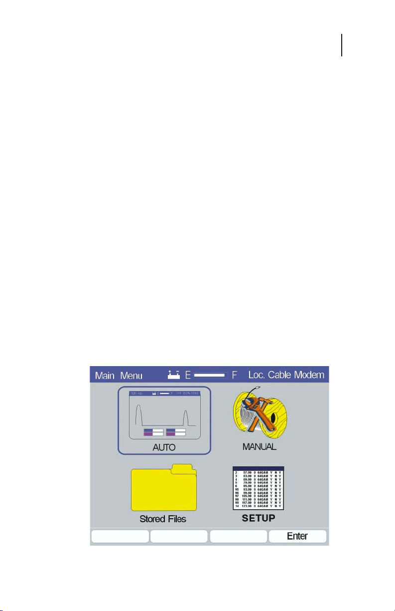
Auto Test Mode .......................................................................34
Manual TDR Measurements ...................................................40
Chapter 4 Specifications ...................................................... 53
Performance Specifications and Key Features ......... 53
Horizontal Resolution .............................................................. 53
Vertical Resolution .................................................................. 53
Range ..................................................................................... 53
Input Protection ....................................................................... 53
Measurements ........................................................................53
Waveform Storage .................................................................. 53
Cable VOP Database .............................................................53
Environment ............................................................................ 54
v
Page 5

CE4000 Cable Explorer TDR
vi
User Manual
Interfaces ................................................................................54
Power ...................................................................................... 54
Display ....................................................................................54
Physical .................................................................................. 54
Chapter 5 Maintenance And Service ................................... 55
Introduction................................................................... 55
Battery Replacement .............................................................. 55
General Maintenance ................................................... 56
Internal Rechargeable Battery ................................................56
Cleaning .................................................................................. 56
Troubleshooting ............................................................ 57
Firmware Upgrades ................................................................ 57
CompactFlash Card Replacement .......................................... 57
Technical Support ........................................................ 59
Warranty ........................................................................ 59
Returning Equipment To Sunrise ................................ 60
Chapter 6 Appendix .............................................................. 63
Additional Cable data .............................................................. 63
Page 6

General Information
Chapter 1
7
Chapter 1
General Information
INTRODUCTION
The CE4000 TDR (Time Domain Reflectometer) module is for
use with the CM1000 Cable Modem System Analyzer. The
Cable Modem System Analyzer tests both upstream and
downstream DOCSIS (Data Over Cable Systems Interface
Specification) paths in terms of error rate, transmit level, lost
packets and cable modem power ranging and registration. The
CE4000 TDR module is used in conjunction with the CM1000
to locate cable faults.
INSTRUMENT OVERVIEW
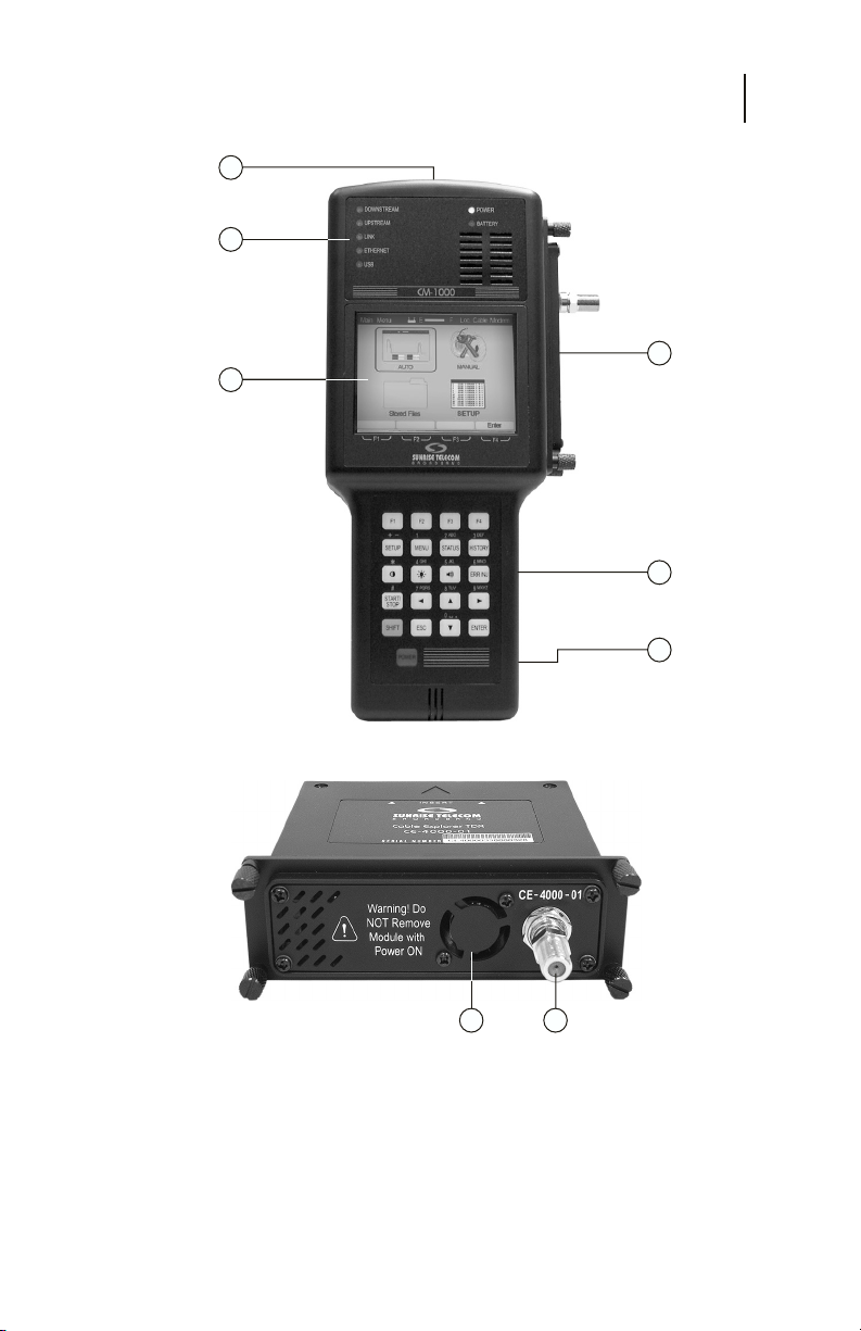
The CM1000 mainframe unit (Figure 1-1) houses the CE4000
TDR plug-in. The hand-held device features a full color display,
which indicates instrument status, signal identification, and
measurement values. The controls are pressure-sensitive keypad
switches with tactile feedback. A 75-ohm “F” connector accepts
the cable connection. A female DB9 provides access to a
computer serial interface connection. The DC input accepts
power from the supplied AC adapter. The weatherized hard
plastic case provides excellent protection from typical bumps
and bangs of normal use. Back panel access is provided for easy
battery pack replacement and the system memory card is readily
accessible from the side panel of the unit.
When installed in the mainframe, the CE-4000 plug-in module
provides comprehensive TDR testing capability. When activated,
the CE4000 TDR goes through the self-mode and provides the
user with a menu of TDR tests. The user may select an Auto Test
mode, Manual Test mode, recall stored data or set up the
configuration of the TDR. Once a cable is selected or the VOP
is set, the Auto Test mode will automatically identify any
impairments on the cable under test, greatly simplifying operation.
Note: This manual covers CE4000 TDR model and its
options. A software upgrade is required to use the
CE4000 module in an existing CM1000. Software
upgrades are available from the Sunrise web site:
www.sunrisetelecom.com.
Page 7

CE4000 Cable Explorer TDR
8
User Manual
CM1000 MAINFRAME AND CE4000 MODULE
1. Mainframe Input/Output
The mainframe I/O section, located at the top of the unit,
provides a female RS-232 9-pin connector (DB-9) for a serial
computer interface. In addition, there is an external power
connection to accept power from the DC power adapter
provided with the unit.
2. Plug-In Module Slot
The plug-in module slot accepts the CE4000 TDR or the
CM1000 Cable Modem Network Analyzer module.
Warning! Do not remove or install a module with the base unit
3. CompactFlash memory slot
4. Battery Access
5. Full Color Display
6. Status LED indicators
7. RF “F” Connector
8. Fan Outlet
powered on or connected to the system or other
equipment. Always turn unit off before removing or
installing a module.
This slot located on the lower right hand side of the unit
houses the mainframe’s CompactFlash memory card. This
memory card further enhances the unit’s ability to
accommodate future memory expansion/upgrades.
An access panel at the lower back of the unit provides easy
access to the user-replaceable battery pack.
The full color display provides clear, easily discernable test
and menu screens in both dark and full sunlight conditions.
Seven LED indicators show the status of downstream
connection, upstream connection, link, Ethernet connection,
power and battery functions.
Connection to the cable under test. Field replaceable.
Exhaust from cooling fan—Do not block airflow.
Page 8
1
Input/Output
Section
6
LED Status
Lights
5
Color Display
General Information
Chapter 1
6
Slot for
Plug-in
Module
3
Memory Card
Battery Access
in Back of Unit
Slot
4
9
CM1000 MAINFRAME
Fan Outlet RF "F"
8 7
Connector
CE4000 Module
Figure 1-1 CM1000 mainframe and CE4000 module
Page 9
CE4000 Cable Explorer TDR
10
User Manual
CE4000 Keyboard Functions
Figure 1-2 CM1000 keypad
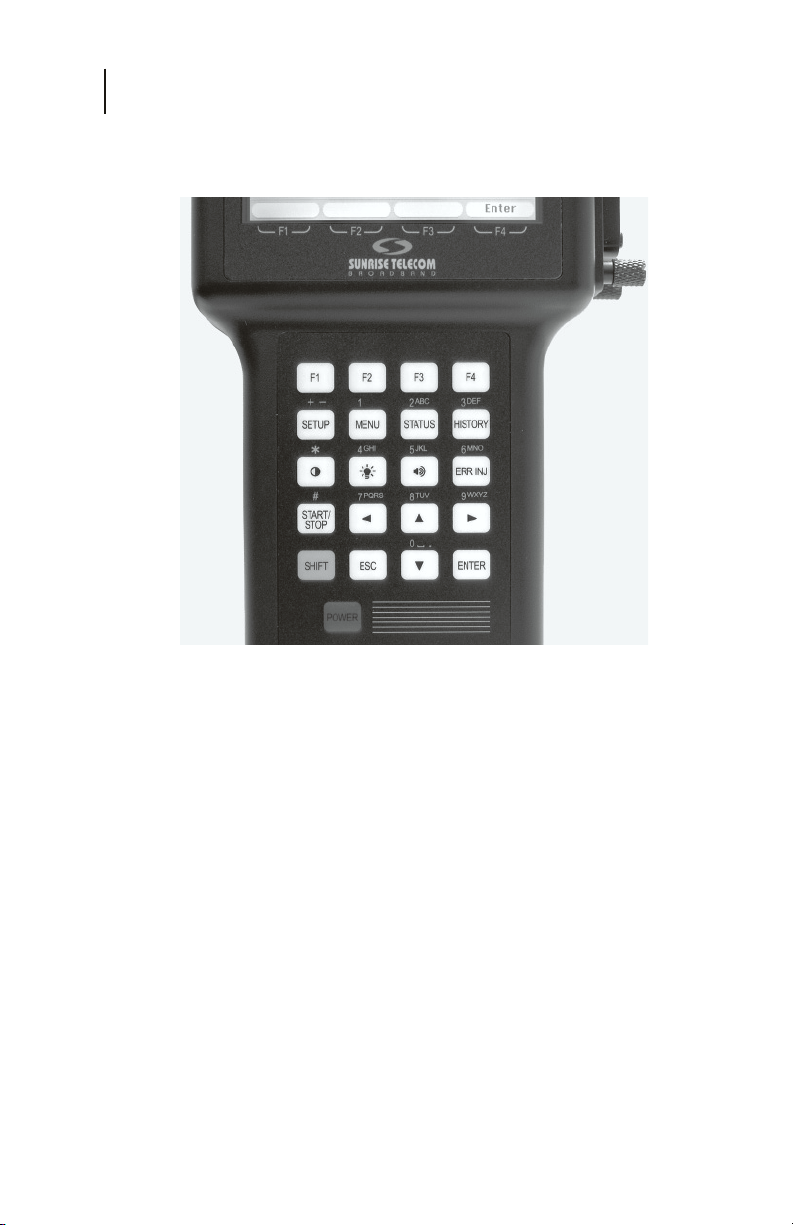
Function Keys F1 through F4
Soft keys to perform various tests and setups. Functions are
described on the display.
SETUP
Takes the user to the Main Setup screen. This screen allows
access to select a cable type, run a cable test on a known cable
or setup the CE4000 configuration information in System
Setup.
MENU
The menu button brings the user to the Main Menu screen.
Choices are Auto, Manual, Stored Data and Setup.
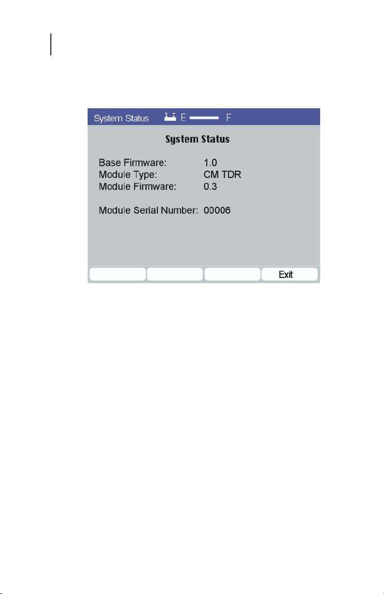
STATUS
Displays current firmware revision, module type, module
firmware and module serial number.
Page 10

General Information
Chapter 1
HISTORY
Not used. (Reserved for a future enhancements)
CONTRAST ( )
Activates the up/down arrows to raise or lower the screen
contrast level.
BACKLIGHT ( )
Turns the screen backlight on or off.
VOLUME ( )
Activates the up/down arrows to raise or lower the
volume.
ERR INJ
Not used in the TDR mode.
START/STOP
Not used in the TDR mode.
LEFT ARROW
Moves cursor or marker to the left.
UP ARROW
Moves cursor upward. Raises level of volume and
brightness when those functions are selected.
11
RIGHT ARROW
Moves cursor or marker to the right.
DOWN ARROW
Moves cursor downward. Lowers the level of volume and
brightness when those functions are selected.
SHIFT
Activates second function on keys (gold lettering).
ESC
Returns user to previous screen or backs up one space in
the alphanumeric mode.
POWER
Turns unit on/off.
Page 11
CE4000 Cable Explorer TDR
12
User Manual
Figure 1-3 Status Display
PREPARATION FOR USE
Follow the instructions for unpacking and inspecting the CE4000.
Compare the received items to the packing list. Read all warnings
and information on power requirements. Follow the initial
checkout procedure to verify that the CE4000 is in good working
order. Be sure to turn off the power of the CM1000 before
swapping modules.
Unpacking And Initial Inspection
Inspect the shipping container when the CE4000 is received.
If the shipping container is damaged, keep the container and
packing materials for inspection by the carrier, and notify the
carrier as well as Sunrise. If the container or shipping material
is damaged, check the contents for completeness. Check the
mechanical and electrical condition of the CE4000. Notify
Sunrise if the contents are incomplete, if there is mechanical
damage or defect, or if the CE4000 does not pass its internal
self-test.
Page 12

General Information
Chapter 1
Shipment Contents
The CE4000 TDR module comes with:
• CE4000-01 module
• CompactFlash memory card
• User manual
Charging Instructions
Charge the CM1000 before its first use for approximately 8
hours. To avoid damaging the internal battery, optimize its life
and guarantee a full charge in 6-8 hours, follow these steps:
• Let the CM1000 cool to room temperature before
recharging.
• Turn the CM1000 OFF before plugging in the
charger.
• Leave the CM1000 OFF while recharging.
• Always leave the charger connected whenever the
CE4000 is not in use.
Caution: Do not charge the CM1000 while above room
temperature or with the unit turned ON. The internal
battery can become hot, reducing its life and
significantly increasing the time required to reach
full charge.
13
Power Requirements
Operate the CM1000 from its internal battery, the supplied
external AC adaptor or the optional 12 VDC adaptor. The
supplied AC adaptor is a universal adaptor that converts 100240 VAC 50 Hz or 60 Hz to 18 VDC at 2.8A maximum. The AC
adaptor can power the unit for normal use. However, fast
charging will take place only when the unit is powered down
before and during charging.
CAUTION: Do not attempt to use any other charger or apply DC
voltage in excess of 18 VDC.
Page 13

CE4000 Cable Explorer TDR
14
User Manual
Safety Precautions
Read and follow these safety precautions before connecting the
CM1000 with CE4000 module to the cable plant.
CAUTION: Do not remove the module from the base unit while
CAUTION: Do not exceed the rated input AC plant operating
CAUTION: Do not remove the module from the base unit or plug
NOTE: The CM1000 is weather resistant but not waterproof
CAUTION: The CM1000 with CE4000 module contains delicate
CAUTION: Do not allow moisture to enter the ventilation holes
CAUTION: Do not allow foreign material to clog or enter the
it is connected to the cable plant or other equipment.
voltage maximum of 90V AC.
in another module while the CM1000 power is turned
on or the unit is connected to any other equipment,
damage to the electronic circuitry or shock hazard
may result.
during normal operation.
electronic circuitry. The chassis and case have been
designed for year-round, day-to-day field use, but
severe mechanical shocks and temperature extremes
could degrade the operation of the unit or damage it.
Do not drop the unit.
on the plug-in module as this may result in damage
to the internal components of the unit or cause
electrical shock when connected to the cable plant.
ventilation holes or to block the fan blades. Blocking
airflow or stalling the fan can cause overheating.
Note: Always follow the procedures outline in this manual
and do not attempt to modify the CE4000 or to use in
any manner not intended or outlined in this manual.
Page 14
First Time Module Installation
When installing the CE4000 into your existing CM1000
chassis, please follow these instructions carefully. The CE4000
module is shipped with a replacement CompactFlash memory
card. To install the module:
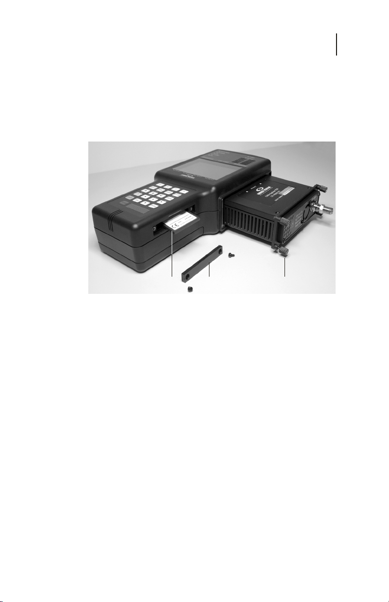
Memory Card Memory Card Cover Thumbscrew
Figure 1-4
General Information
Chapter 1
15
1. Power down the CM1000.
2. Loosen the four module thumbscrews and remove
the CM1000 module. Be sure to place the CM1000
module in the optional carry bag or other safe
location.
3. Insert the CE4000 TDR module, seating it firmly
and tighten the four thumbscrews.
4. Remove the CompactFlash memory card cover,
eject and remove the original memory card. See
detailed instructions for memory card replacement
in the Service section of this manual.
5. Insert the new CompactFlash card, being sure that
it is fully seated in the socket (Sunrise label facing
down) and replace the cover.
6. Connect the AC charger to the CE4000.
Page 15

CE4000 Cable Explorer TDR
16
User Manual
7. After turning the power on, a message will be
displayed that the CE4000 is loading. This process
takes approximately 10 minutes. Once the process
is completed, follow the on-screen instructions to
cycle power (turn off and back on).
8. Installation is complete and the CE4000 TDR is
ready for use. The new memory card contains the
firmware program for both the CM1000 Cable
Modem System Analyzer and the CE4000 TDR.
The memory card does not have to be swapped
when you switch back to the CM1000 Cable
Modem module.
Page 16

Chapter 2
Setup
17
Chapter 2
Setup
GETTING STARTED
Power Up To Self Test Screen
Press the Power button. The green power LED will light as the
unit boots up and performs its self-test. After about 10 seconds,
each of the status LEDs in the upper left portion of the instrument
will individually blink green and then red as the unit completes
the test process. The screen will display the following information:
Performing Self Test:
Serial NVRAM Pass
Loading FPGA (Please wait)
You may not see the last reported “Pass” because the unit
immediately goes to the Main menu (Figure 2-1) when the test
is complete with all criteria passed.
Figure 2-1
BASIC SCREEN LAYOUT
The basic screen layout for the CE4000 remains consistent
throughout the menus. The center of the screen always displays
the current command icons and test information.
Page 17

CE4000 Cable Explorer TDR
18
User Manual
The blue bar at the top of the screen provides current status
information for the module. The current screen name is shown
on the left side of the banner. In the center of the bar, the battery
status is displayed. A battery icon indicates the unit is on battery
power. An AC plug icon indicates the unit is externally powered.
The gauge to the right of the Power icon provides a relative
indication of battery status. This gauge indicates “charging”
when either an external power source is connected or the unit is
in charge mode. On the right side of the blue bar, the VOP and
Test Pulse width are displayed. At the bottom of the screen are
the function indicators that correspond with the F1 through F4
function keys.
Main Menu Screen Detail
The CE4000 is designed for easy-to-use operation. Any of the
menu choices may be selected by using the left/right or up/down
arrow keys and pushing either Enter (F4) or the Enter key. The
four Main menu choices are:
AUTO
Select the Auto TDR test mode by pressing Enter (F4) to initiate
an immediate series of automatic TDR tests. The CE4000 will
use the current (last used) VOP and automatically sequence
through the various pulse widths available, testing the connected
cable. It will configure the display to provide the best
representation of the first fault on the cable under test. The loss
of the cable under test (at the frequency of the test pulse) and the
distance to the fault are displayed at the bottom of the screen.
MANUAL
Choose the Manual mode to make adjustments to pulse width,
vertical gain, horizontal gain and position, and to set cursors for
measuring distance and loss. Operational details are provided in
Chapter 3. The initial Manual screen uses the first Auto test
screen as a starting point.
STORED DATA
The Stored Data menu provides access to the data files stored as
a result of screen saves. Operational details are provided in
Chapter 3.
SETUP
Provides access to the CE4000 Setup and Configuration icon
screen. Setup includes Select Cable, Cable Test and System
Setup.
Page 18

SETUP OVERVIEW
All Setup menus for the CE4000 can be accessed by pressing the
Setup key located just below the F1 key on the keyboard or by
selecting the System Setup icon on the Main menu. The Main
Setup screen is shown in Figure 2-2. Utilize the keyboard arrows
to highlight the setup screen you wish to edit and press Enter
(F4). The Setup menu label in the upper left corner of the screen
easily identifies this screen type.
Chapter 2
Setup
19
Figure 2-2
CABLE SELECT
Select the type of cable under test from the built in table of 50+
common cables or add your own data. Insert new cables or edit
the existing data. The cable VOP is used to determine the
distance to faults on the cable.
SYSTEM SETUP
Selecting the System Setup provides access to general system
functions such as backlight and power down timers, date/time
settings, RS232 serial port setup and display preferences.
CABLE TEST
If the VOP of a cable is unknown, the VOP may be measured
using this utility for a known length or known VOP.
Page 19

CE4000 Cable Explorer TDR
20
User Manual
Figure 2-3
System Setup Detail
SYSTEM
The System Setup screen (Figure 2-3) can be accessed at any
time by pushing the Setup button on your CE4000 keypad,
highlighting the System icon and pushing Enter (F4).
The Next Field (F1) key allows the user to move forward
through the screen menu. The Prev Screen (F2) key allows the
user to move backward through the screen menu. The Save
(F3) key activates and saves any changes. Exit takes you back
to the Setup menu.
BACKLIGHT TIMER
The backlight timer default is Disable. When Enabled, it will
automatically turn off the backlight after one minute of operation,
if no keys are pressed. Press Save to activate your choice and
save the parameter to memory. Even with the backlight timer
Disabled, the CE4000 will automatically turn the backlight off
after 15 minutes if no keys are pressed.
POWER DOWN TIMER
The Power Down Timer default option is Enable. This option
will power the unit down after a 3-minute period of inactivity.
When disabled the unit will remain powered on until turned off
manually utilizing the power button. Press Save to activate your
choice and save the parameter to memory.
Page 20

Chapter 2
Setup
TIME & DATE
The time and date on the CE4000 is set from the System Setup
screen (Figure 2-3). The time and date are in the formats
hh:mm:ss and mm, dd, yy. Simply use the next field (F1) or the
Prev Field (F2) keys to highlight the parameter you would like
to change and use the Up/Down arrow keys to increment through
the choices. The clock in the CE4000 is set in a 24-hr time
format. Press Save to activate your choice and save the parameters
to memory.
SERIAL PORT SETTINGS
The serial port speed settings may be set by highlighting them,
using the Next Field (F1) or the Prev Field (F2) keys and then
choosing the desired value by pressing the Up/Down or Left/
Right arrow keys. Press Save to activate your choice and save the
parameter to memory.
Available Serial port speeds (baud rates):
115,200 and 19,200 and 9600.
UNITS
The CE4000 may be set to US measurement units of feet (ft) or
to meters (m).
PLOT FILL
The default mode is Disabled. In the default Disabled mode the
incidence pulse and reflections are displayed as a simple line
graph on the display. When Plot Fill is Enabled, the TDR trace
will be filled in under the trace to enhance the viewability.
21
PLOT 1 COLOR
The color of the main TDR trace may be selected from the list of
Magenta, Red, Cyan, Green, Blue, Black and Brown. The
default is Magenta.
PLOT 2 COLOR
The color of a second trace, used when comparing traces, may
be selected form the list of Magenta, Red, Cyan, Green, Blue,
Black and Brown. The default is Blue.
Page 21
CE4000 Cable Explorer TDR
22
User Manual
Cable Select Detail
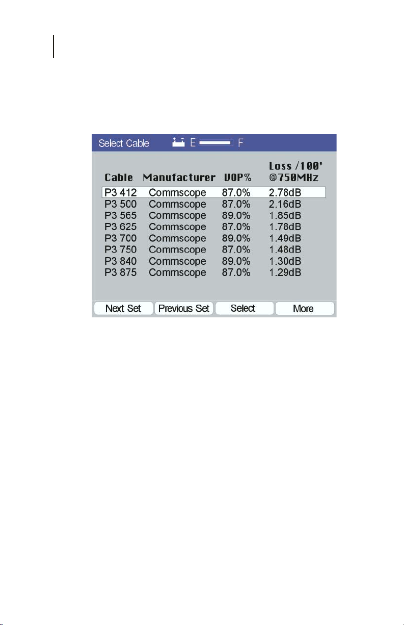
To access the Cable Select selection screen (Figure 2-4), press
the Setup button on the keypad, highlight the Cable Select icon
using the arrow keys and press ENTER (F4).
Figure 2-4
SELECT A CABLE
For cable selection, select the Cable Select icon and use the Next
Set (F1) or Prev Set (F2) key to sequence through the pages of
cable data. Next, use the up/down arrows to highlight the cable
to be made active and then press the Select key (F3). The cable
type, manufacturer, VOP (velocity of propagation) and typical
loss of 100 feet of cable at 750 MHz are all displayed. The VOP
of the selected cable will be used in calculating the distance to
cable faults in the TDR mode. Cable data for approximately 50
common cable types is available.
Cable - Up to 10 characters describing the cable type.
Manufacturer - Up to 12 characters describing the
manufacturer of the cable.
VOP - Three digits describing the cable’s VOP as a
percentage to the nearest 0.1%.
Loss/100 feet at 750 MHz - The typical loss of the
cable at 750 MHz for a length of 100 feet.
Page 22
Chapter 2
Setup
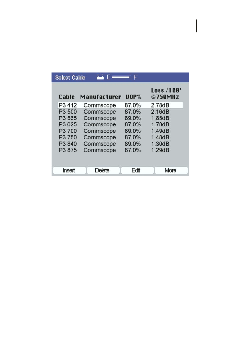
Additional functions, as shown in Figure 2-5, are available by
pressing the More (F4) key. Cable data may be edited or changed
using the Insert (F1), Delete (F2) or Edit (F3) key. Pressing More
again returns you to the original Cable Select screen.
Figure 2-5
23
INSERT
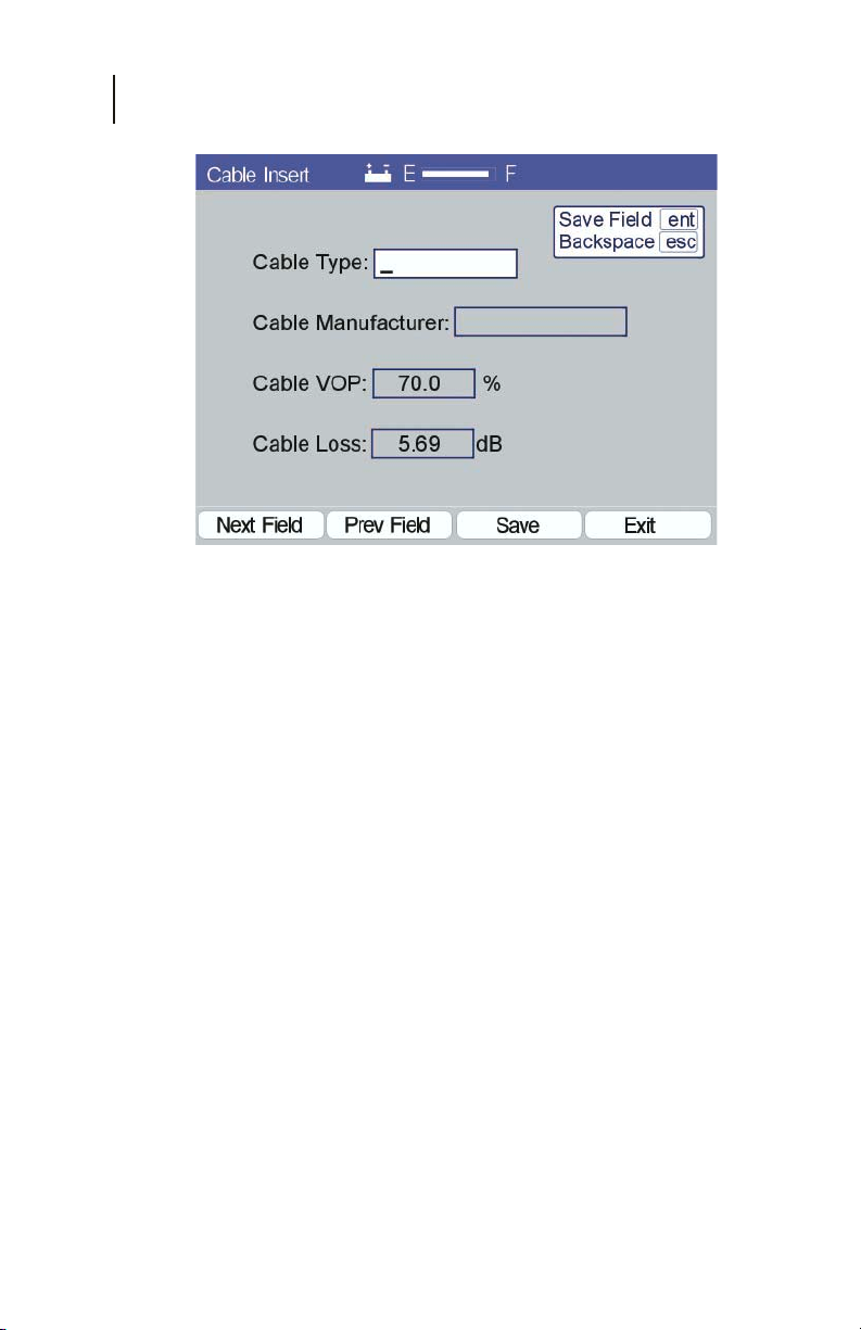
Press the Insert (F1) key to open a new screen, similar to the one
shown in Figure 2-6 (data fields blank), to provide fields for
entering the new cable data.
Cable Type - Enter up to 10 characters describing the
cable type using the alphanumeric keypad.
Cable Manufacturer - Enter up to 12 characters
describing the cable manufacturer using the
alphanumeric keypad.
VOP - Use the Up and Down arrow keys to increment/
decrement until the desired VOP is displayed in the
three digits describing the cable’s VOP as a percentage
(to the nearest 0.1%).
Loss / 100 feet at 750 MHz - Use the Up and Down
arrow keys to increment/decrement until the desired
loss is displayed in the three digits describing the
cable’s loss per 100 feet at 750 MHz (to the nearest
0.01 dB).
Page 23
CE4000 Cable Explorer TDR
24
User Manual
Figure 2-6
DELETE
Press the Delete (F2) key to delete the currently highlighted
cable.
Note: No warning or confirmation is provided. Data for the
highlighted cable is deleted and can only be recovered
by re-entering the data. A list of the standard cables
and data is provided in the Appendix for reference.
EDIT
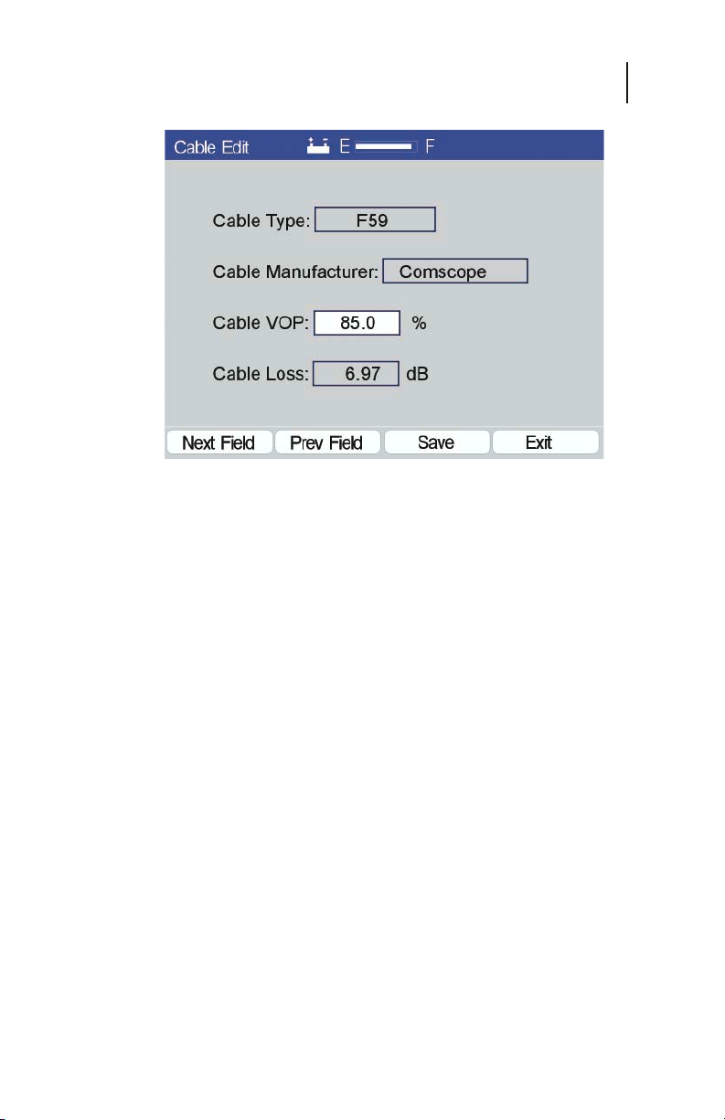
Press the Edit (F3) key to open the screen that displays the data
for the highlighted cable (Figure 2-7). Only the VOP and the
Cable Loss may be edited. Use Insert to add additional cable
types.
SELECT A FIELD
Press Next Field (F1) or Prev Field (F2) to sequence through the
VOP and Loss data fields. Data may be changed by using the up
and down arrow keys.
SAVE
Save changes by pressing the Save (F3) key.
Page 24
Chapter 2
Setup
Figure 2-7
EXIT
Press Exit to return to the Select Cable main screen.
Cable Test
Cable Test determines the VOP of a cable if the length of the
cable is known. This simple method only requires knowing the
length of cable. The length of the cable is entered into the
CE4000 and the unit calculates the appropriate VOP for that
length of cable under test.
25
Since the VOP is directly proportional to the distance
measurement, a 1% error in the VOP will project a 1% error in
the distance measurements. Determining an accurate VOP is
critical to the accuracy of the distance measurements. When
possible, choose a test cable of at least 100 feet (30m) to reduce
calculation errors. Longer cables increase the accuracy, but may
be difficult to measure accurately. Also avoid cable on reels,
since the coiling slightly affects the VOP. Lengths marked on
spools are often inaccurate.
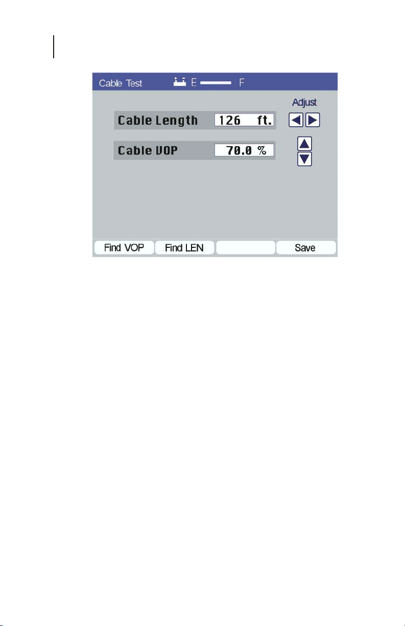
To determine the VOP of a cable using the CE4000, select the
Setup icon from the Main Menu or press the Setup key. Next,
select the Cable Test icon and press enter. The screen shown in
Figure 2-8 is displayed.
Page 25
CE4000 Cable Explorer TDR
26
User Manual
Figure 2-8
SET CABLE LENGTH
Use the Left/Right arrow keys to adjust the Cable Length
displayed to the length of the cable under test. The arrow keys
will increment or decrement the numbers displayed slowly when
first pressed. The step size of change will increase the longer the
key is pressed. For simple operation, hold down the key, noting
the step size as the numbers change. Release the key momentarily
when the number approaches the desired setting. This reduces
the step size. Then press the key for individual steps to fine-tune
the setting.
Measure VOP - Once the test cable’s length is set and
connected to the CE4000, press the Find VOP (F1)
function key. The CE4000 will calculate and display
the Cable VOP (Figure 2-8).
Measure LEN - The Cable Test mode can also be used
to make quick cable length measurements by setting
the VOP and pressing the Find LEN (F2) function key.
The CE4000 will calculate and display the cable length
(Figure 2-8).
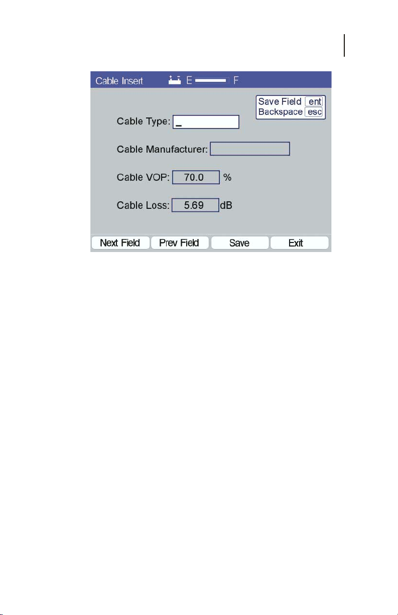
Save - Be sure to save the information if you want to
use the measured VOP for subsequent cable tests.
Press Save (F4) to display the screen shown in Figure
2-9. You must enter a cable type and manufacture in
this screen for the information to be saved.
Page 26
Chapter 2
Setup
FIGURE 2-9
CABLE TYPE
Use the alphanumeric keypad to enter up to 10 characters to
describe the cable type and press Enter. If you press Next Field
or Prev Field before Enter, the entry will be lost. Use the ESC key
to back up and delete the previous character input.
27
CABLE MANUFACTURER
Use the alphanumeric keypad to enter up to 12 characters to
describe the cable manufacturer and press Enter. If you press
Next Field or Prev Field before Enter, the entry will be lost. Use
the ESC key to back up and delete the previous character input.
SAVE
Be sure to save the entered information if you want to use it for
subsequent cable tests. Press Save (F3) to save the information.
EXIT
Exit completes this operation and returns you to the Select Cable
screen (Figure 2-4). To use the information just entered, select
the highlighted cable by pressing the Select (F3) function key.
Page 27

CE4000 Cable Explorer TDR
28
User Manual
Page 28
Chapter 3
Measurements
29
Chapter 3
Measurements
TDR BASICS
Locating Cable Faults
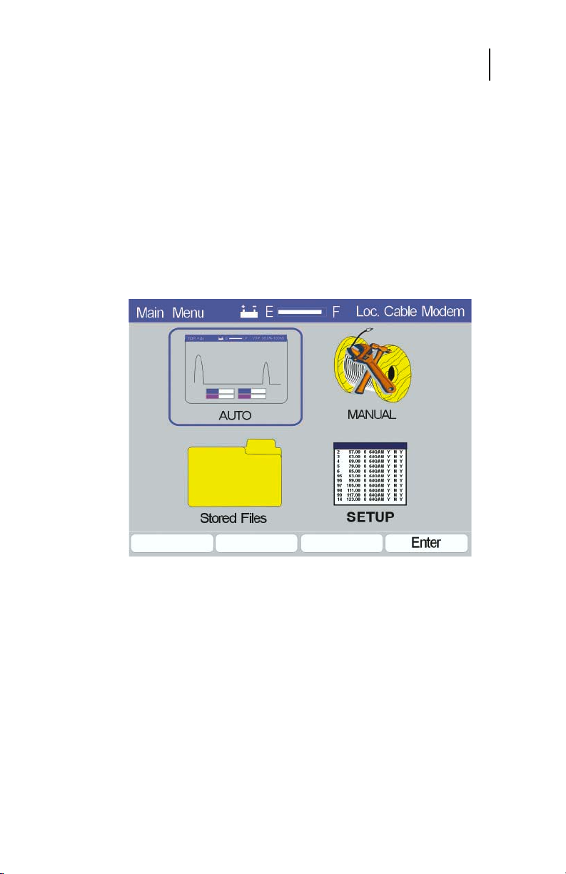
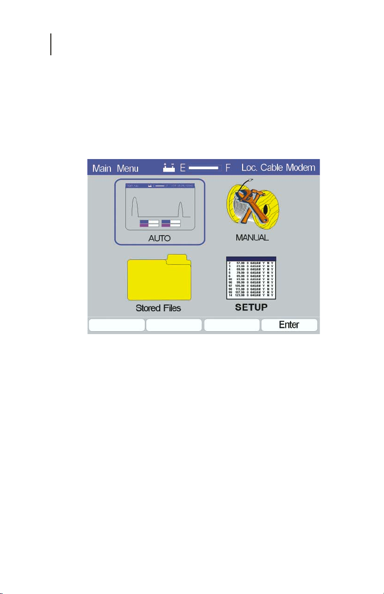
The CE4000 TDR has two cable test modes, Auto and Manual.
Select the desired icon on the Main menu for the preferred mode
of operation. Press the MENU key at any time during operation
and the unit will return to the Main Menu screen (Figure 3-1).
Figure 3-1
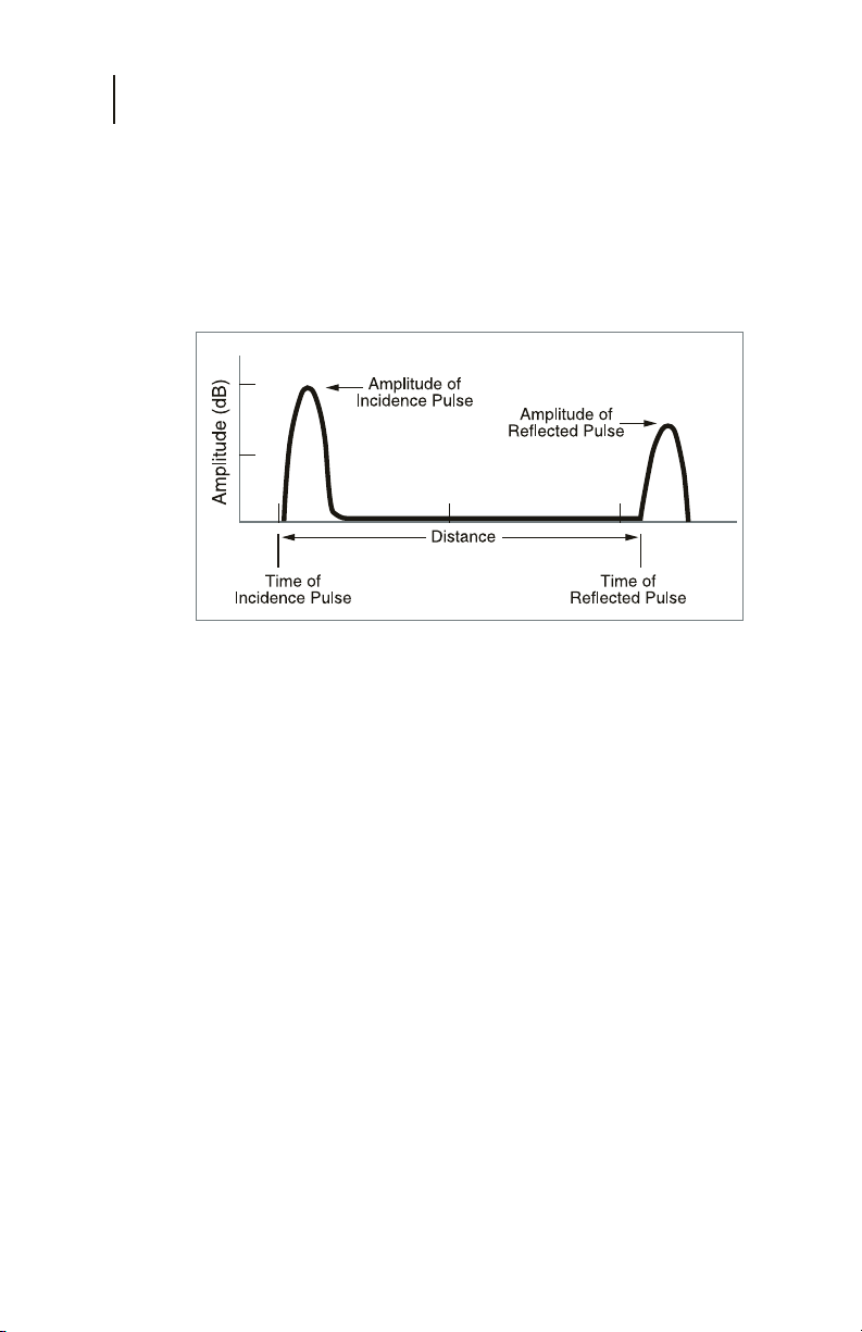
The CE4000 operates on the same principle as most TDRs. A
test pulse, typically called the incidence pulse is transmitted
into the cable under test. The pulse travels down the cable at
a speed that is controlled by the properties of the cable. The
speed is called the VOP or velocity of propagation and is
measured as a percentage or decimal fraction of the speed of
light. When the pulse reaches a discontinuity in the cable
some of the energy (all of the energy if the cable is open or
shorted) is reflected back up the cable toward the original
source. The TDR measures the time required for the round
trip of the reflected pulse from the TDR, from which it was
launched, to the fault and back to the TDR. The distance to the
fault is then calculated by the formula:
Page 29

CE4000 Cable Explorer TDR
30
User Manual
VOP
The velocity of propagation is the speed at which the signal
travels on the cable under test. The time required for the
television signals to reach the customers is normally not a
concern, however some delay is present in the system, due
primarily to the delay of the cable and filters in the network.
The VOP of a cable is the speed at which the signal travels
divided by the speed of light and is expressed as a decimal or as
a percentage (i.e. .85 or 85%). Most hard line cable will have a
VOP of .87 or 87% or better. Typical (newer) drop cable will
have a VOP of 80% to 85%. Older drop cables may have VOPs
as low as 70%.
Approximately 50 cables are pre-programmed into the CE4000
for use. The user may add, delete or edit this data table. (VOP
specifications are available from the cable manufacturer’s data
sheet.) As shown in the previous equation, TDR simply measures
the time between the incidence and reflected pulse and calculates
the distance to the fault. Obviously, the accuracy of the VOP has
a direct relationship to the accuracy of the resultant distance
measurements. A 1% error in the VOP will result in a 1% error
in the distance measurement, plus any inaccuracy in the time
measurement capability of the TDR. A cable’s VOP can also be
measured if the cable’s length is known by using the same
formula. This procedure is detailed in the Operation section of
this manual.
PULSE WIDTH
The pulse is 1/2 of a sine wave (negative pulse, but displayed as
positive). The pulse width is typically programmable, so that
longer pulses can be used for longer ranges—pulses with more
energy can travel longer distances. The cable under test exhibits
the same loss characteristics on the incidence pulse as they do on
the typical RF signals on the network. The longer the cable is, the
higher the loss. Note that the reflected pulse has traveled down
the cable and back, thus it has experienced twice the cable
attenuation.
Page 30
Chapter 3
Measurements
Figure 3-2
Short pulse widths are advantageous for two reasons. First, the
time period of the pulse prevents seeing reflections that occur in
the time period between the rise and fall of the incidence pulse.
Secondly, multiple reflections that are close together are seen as
a single fault because the time period of the reflected pulse
obscures any other reflections between the time of the rise and
fall of the reflected pulse.
31
The distance associated with the time during the rise and fall of
the incidence pulse is called the “dead zone”—an area where the
TDR cannot make measurements. The CE4000 eliminates this
dead zone by incorporating a built in delay line, which
effectively moves the “0 distance” to the right of the incidence
pulse allowing measurements right up to the connector on
the CE4000.
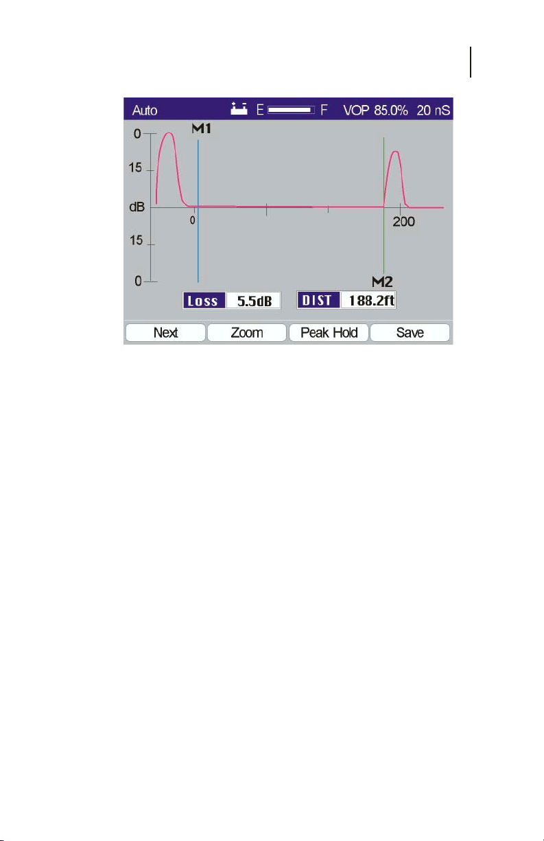
Figure 3-2 shows a typical CE4000 TDR display. The incidence
pulse is shown to the left of the display (just left of the “0” on the
horizontal distance scale). The reflection pulse can be seen just
below the 200-foot mark on the horizontal scale.
The CE4000 offers pulse widths of 10 nSec, 20 nSec, 50 nSec,
100 nSec, 200 nSec, and 350 nSec. Faults at longer distances
may be masked by the cable loss. Longer pulses represent more
Page 31
CE4000 Cable Explorer TDR
32
User Manual
energy and a lower frequency and thus more energy is transmitted
and less loss is present in the cable. This allows a longer range.
The range is dependent on the VOP and pulse width used for the
test. A table providing maximum ranges for each pulse width is
provided in the Appendix.
Figure 3-3
THE TDR TRACE
The TDR trace provides detailed information about the cable
under test. The horizontal axis is calibrated in distance, either
feet or meters. The vertical scale is calibrated in dB of loss with
both positive and negative axes. The positive axis represents
reflections, which result from impedances higher than the nominal
75W impedance of the cable. The negative axis represents
reflections that result from impedances lower than the nominal
75W impedance of the cable. Thus, an open cable will result in
a positive reflection pulse and a shorted cable will result in a
negative inclined reflection pulse. A perfect cable, terminated in
its characteristic impedance will absorb all of the energy from
the incidence pulse and no reflection will be seen on the TDR.
High impedance series mismatches (corroded or loose connectors,
loose seizure screws, and radial cracked sheath) will produce
positive inclined trace signatures.
Low impedance parallel mismatches (kinked cable, water ingress,
and shorts) will produce a negative inclined trace on the TDR
screen.
Page 32
Chapter 3
Measurements
The amplitude of the reflected pulse is proportional to the return
loss of the cable at the fault location plus two times the cable loss
between the TDR and the fault. Measuring the reflected pulse
from an open or shorted cable and dividing the resultant by two
can measure the loss of a cable. The cable loss is the loss at the
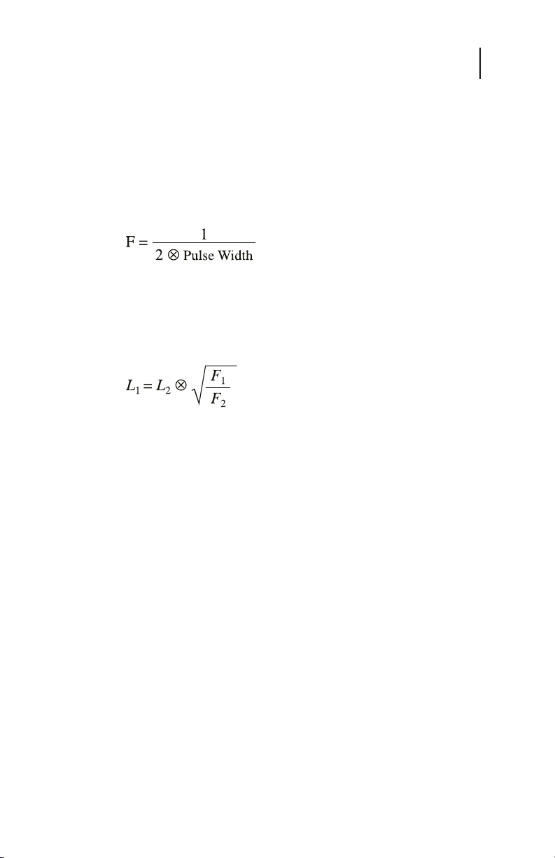
frequency of the incidence pulse. The frequency of the incidence
pulse is equal to the inverse of two times the pulse width.
Since the loss of the cable is proportional to the frequency, the
loss of the cable will depend on the pulse width used for the test.
Cable loss may be estimated for any frequency, when the loss is
known at some frequency. Cable loss may be estimated by the
formula:
Often, faults are not pure opens or shorts and therefore may
result in a complex reflected trace. System components typically
have reactive components (capacitors and inductors) and will
produce complex trace displays. Although the TDR is not
designed to test system components, each component will have
a typical signature that often can be used to determine the
difference between a good and bad component. A collection of
sample traces is provided in the Appendix.
33
See the Operation section of this manual for procedures to make
specific measurements with the CE4000, including cable loss,
return loss and distance to a fault.
LOSS AND RETURN LOSS (RTL)
The severity of a fault is determined by the amplitude of the
reflection. More severe faults will reflect more of the energy
back to the TDR. The vertical scale is calibrated with 0 dB equal
to the amplitude of the incidence pulse (both positive and
negative axes). The scale then increases logarithmically as it
approaches the center, where the horizontal axis crosses. The
loss may be read from the trace using the vertical axis or more
accurately read from the digital readout. The severity of the fault
or the quality of the termination is typically measured in Return
Page 33
CE4000 Cable Explorer TDR
K
34
User Manual
Loss (RTL). RTL is the ratio of the reflected signal to the
transmitted signal in dB. A 20 dB return loss means that the
reflected signal is 20 dB down from the transmitted signal.
Manufacturers provide Return Loss specifications for most RF
components.
OPEN
SPLICE
CORRODED
CONNECTOR
WET SPLICE
DIPLEXER
OR TUNER
SHORT
TAP OR
SPLITTER
CABLE KIN
WATER
INGRESS
Figure 3-4
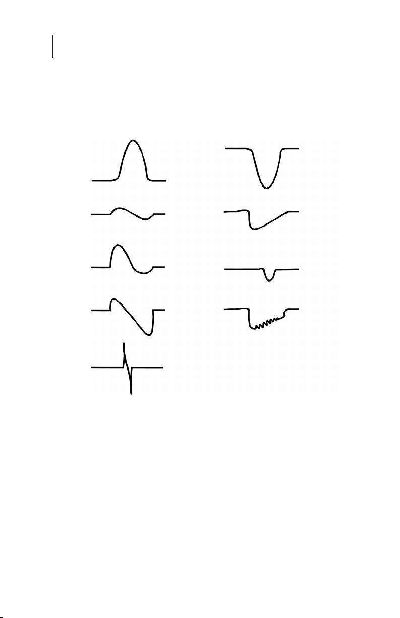
TRACE SIGNATURES
The TDR trace can be interpreted beyond the typical open and
short condition. Cable impairments and components on the
network have characteristic traces or signatures, representing
both good and bad performance. Figure 3-4 gives examples of
typical trace signatures for common cable faults and components.
Some variation should be expected in component signatures.
Technicians should note the characteristic trace signature of
good components as they use the TDR to recognize the bad
traces when testing similar components. Remember that the
cable under test has loss, which increases with distance, so the
Page 34
farther the reflection is from the TDR, the higher the cable loss.
Be sure to increase the TDR’s vertical gain to display any
impairments that could be hidden by the cable loss.
TDR TESTS WITH THE CE4000
The CE4000 has two basic TDR modes, Auto and Manual.
Auto is an automatic mode which automatically tests the
cable connected to the CE4000, sets the Pulse Width,
Horizontal Gain and Position, Vertical Gain and places the
Markers on the first fault to make a distance measurement to
the fault.
Manual is a secondary mode that allows the user to control all of
the TDR functions. To provide a user-friendly starting point, the
initial Manual screen displays the result of an AUTO test. This
places the first fault (if there is a fault) on screen and sets all of
the TDR parameters. After the initial screen is displayed the user
may change any of the settings for Pulse Width, Horizontal
Position and Gain, Vertical Gain and move the two markers as
desired.
To select a TDR test mode, select either the Auto or Manual icon
from the Main Menu (Figure 3-5). From any screen, press the
Menu key and use the arrow keys to highlight the desired icon
and press Enter.
Chapter 3
Measurements
35
Figure 3-5
Page 35
CE4000 Cable Explorer TDR
36
User Manual
Auto Test Mode
When the Auto test mode is selected, the CE4000 TDR will use
the last selected cable data (see Setup section) and initiate a
series of TDR tests. The initial screen will take several seconds
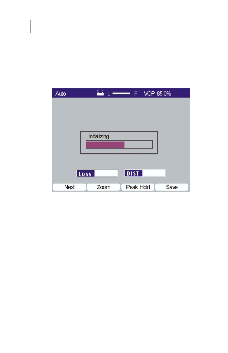
to appear, as the Auto test is being performed. A progress bar is
displayed with the text “ Initializing” (Figure 3-6)
Figure 3-6
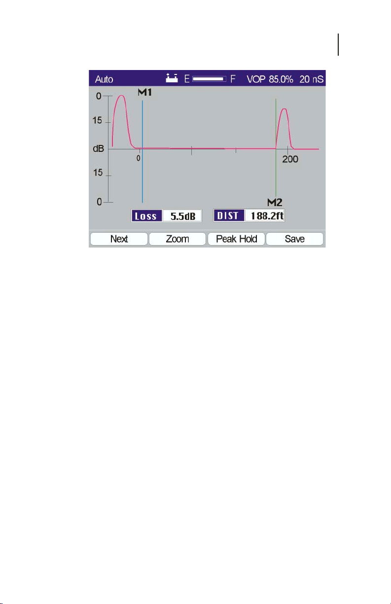
Once the tests are completed, the Auto test screen is displayed
(Figure 3-7). The cable VOP used for the test is shown in the
upper right corner. The Pulse Width, Horizontal Gain and
Position, Vertical Gain and Markers are all set automatically.
Although multiple faults may be present and found on the cable
under test, the CE4000 will automatically go to the first cable
fault, place the marker at that location and display the distance
to the fault.
Auto is the fastest and most accurate mode of operation.
Under microprocessor control, the CE4000 can sequence
through the various TDR settings very quickly and provide
the best display of the test results. Since the Auto test
results are calculated based on the raw test data, the
accuracy is not subject to the limitations of the display
resolution as with most TDRs.
Page 36
Chapter 3
Measurements
Figure 3-7
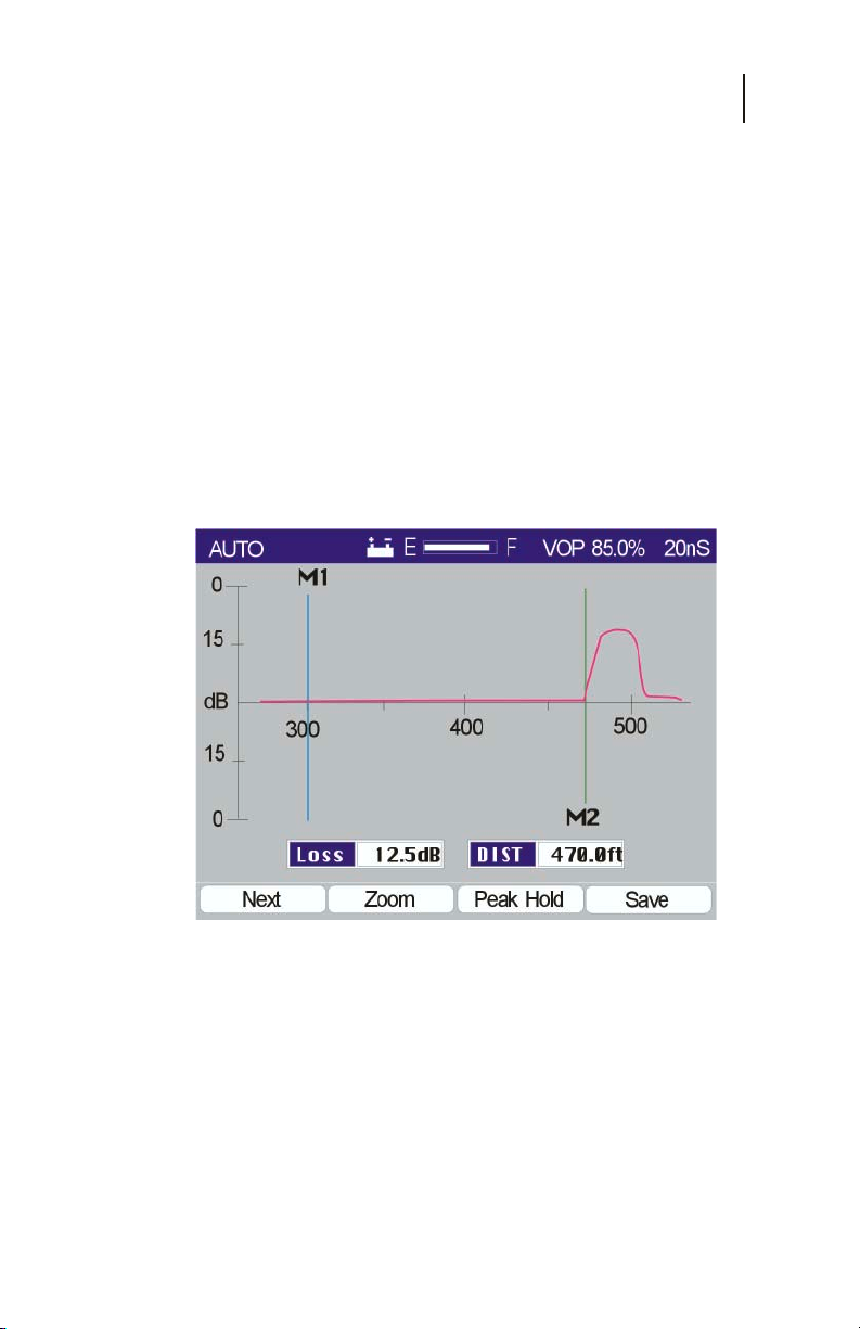
DISPLAY
The CE4000 color display provides comprehensive information
and measurement details.
Top Bar - The top bar provides basic unit information,
including the current test mode “Auto”. The battery
icon indicates operation from battery power; the bar
graph indicates the battery charge condition (full),
the VOP (85.0%) used for the test and the Pulse
Width (20 nSec).
37
Axes - The horizontal and vertical axes depict the
distance to the fault and the severity of the fault in dB
of Return Loss. The scale of the axes is dependent on
automatic or manual settings. Calibrated marks with
numbers are provided.
Markers – Two markers are provided and automatically
placed in the Auto test mode. The Loss and DIST
measurements are made at the markers.
DIST - Distance is the measurement of the cable’s
distance from the TDR to the reflection from the fault.
Loss - The Loss is the measurement of the Return Loss
at the fault plus two times the cable loss over the
distance from the TDR to the fault.
Page 37
CE4000 Cable Explorer TDR
38
User Manual
The TDR displays the distance measurement both on the
horizontal scale and digitally based on the placement of the M2
marker. M1 is automatically placed at the beginning of the cable
under test and M2 is placed at the point of the reflection (fault).
The loss at the point of the reflection is also displayed, indicating
the loss to the reflection—or the ratio of the level of the
reflection to the level of the incidence pulse in dB. The vertical
scale is logarithmic, with level marks, also indicating the ratio of
the reflected pulse to the incidence pulse.
Note: An open or shorted cable would only measure the
loss of the cable between the TDR and the fault,
since both (short and open) will reflect 100% of the
pulse.
At the bottom of the display the user is offered additional
function keys, Next (F1), Zoom (F2), Peak Hold (F3) and Save
(F4) to further investigate the results of the TDR auto test.
NEXT - The Next (F1) function will sequence the
CE4000’s Auto test mode from the first fault to any
subsequent faults on the cable under test, as shown in
Figure 3-8.
Figure 3-8
Page 38
Chapter 3
Measurements
The marker is automatically set to the next reflection fault, the
vertical and horizontal scales are adjusted and the measurements
are displayed. If no faults are found, the CE4000 will display a
message over the TDR screen indicating “No Faults“ and the
range of the TDR test. Once “No Faults” are found, the TDR will
wrap back around to the original test screen displaying the first
fault.
ZOOM
The Zoom (F2) function key readjusts the CE4000 display,
increasing the horizontal gain and moving the M2 marker to the
center of the screen (Figure 3-9). Although the M1 marker may
not be displayed, it remains the reference for distance
measurements. Use the Up and Down arrows to increase or
decrease the vertical gain.
39
Figure 3-9
Page 39
CE4000 Cable Explorer TDR
40
User Manual
PEAK HOLD
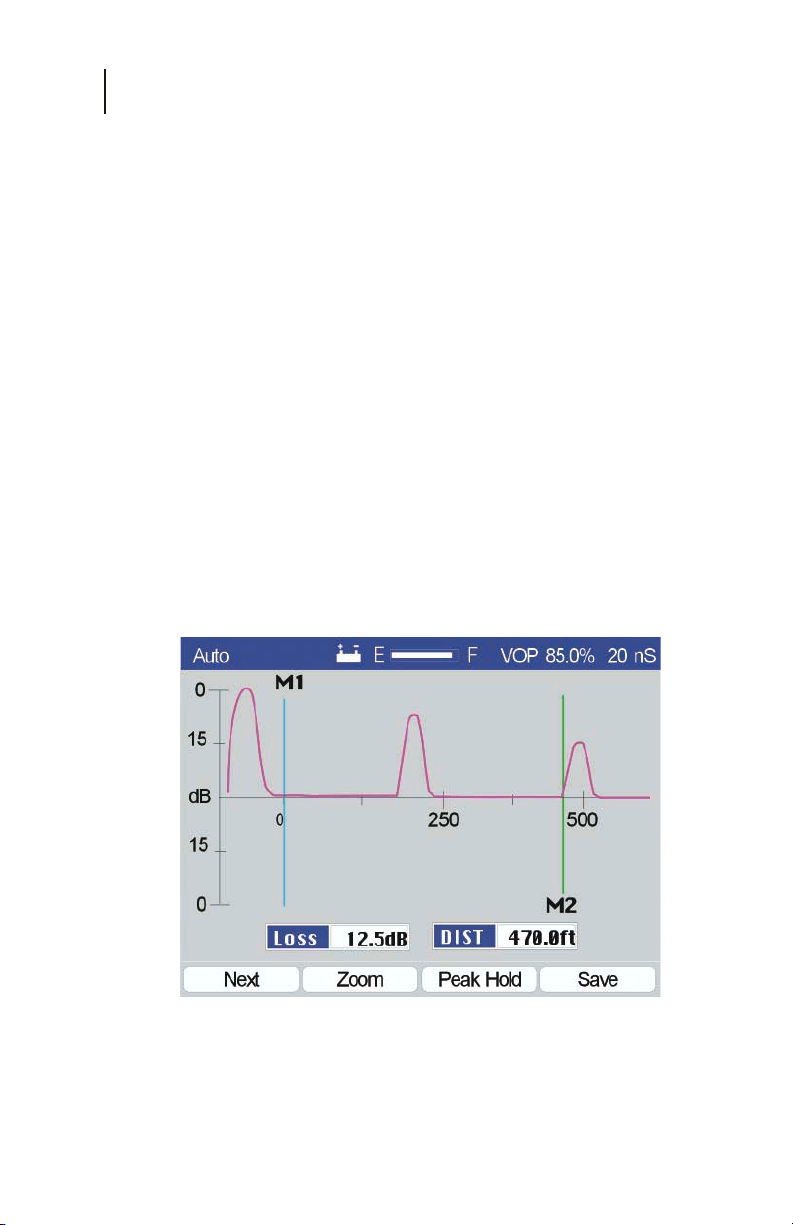
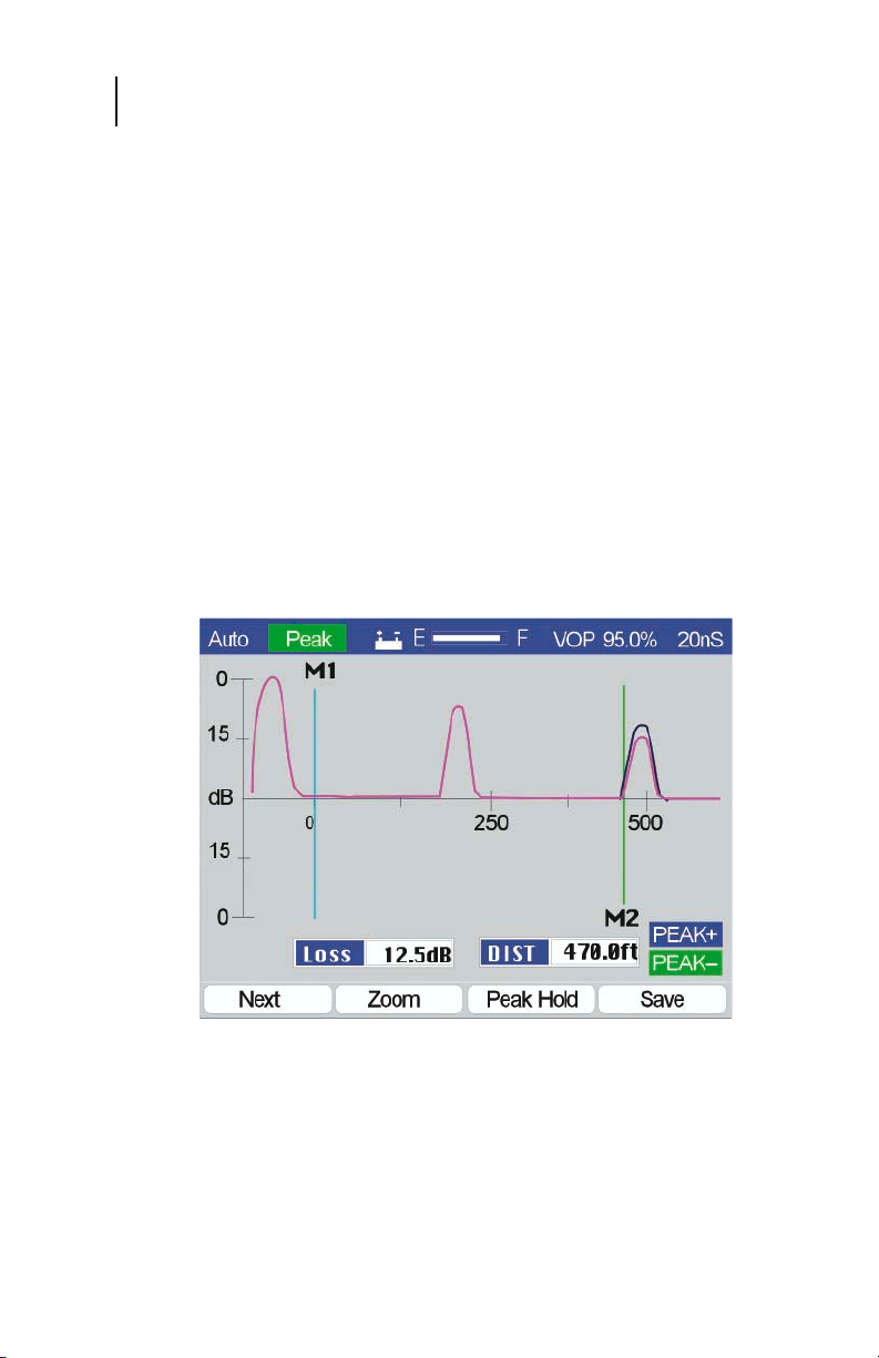
The Peak Hold (F3) function key will cause the CE4000 display
to hold the worst-case peak measurements—both positive (near
open) and negative (near short), as shown in Figure 3-10.
The positive peak trace is displayed in blue, the negative peak
trace in green and the normal trace (current test result) in purple.
In Figure 3-10, note that the highest loss (worst case) is held
on the display (at 470 feet), while the current display (less
positive result) is displayed below the worst-case result. Use
this display type to troubleshoot intermittent-type problems
where the cable may alternately test good and then bad. While
in the Peak Hold mode, the user would flex or stress the
components under test to see if good or bad results can be
displayed. The TDR captures the worst-case results.
Note: The display update speed will slow down, since the
TDR is displaying three separate traces alternatively.
Figure 3-10
Page 40
Chapter 3
Measurements
SAVE
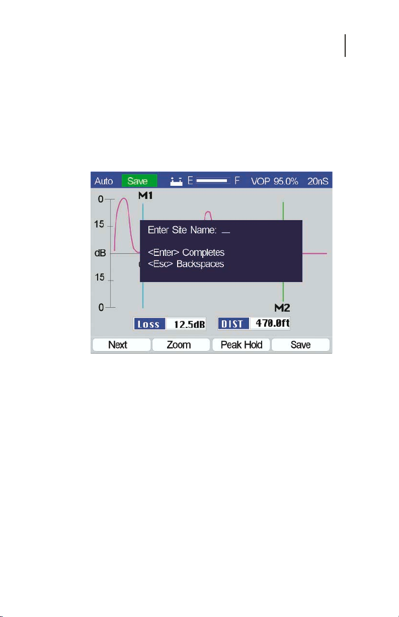
The Save (F4) function key freezes the current screen to allow
entering a Site Name for the screen to be stored (Figure 3-11). Up
to 10 characters may be entered to describe the screen data. Use
the alphanumeric keys to enter the information. Press ESC to
back up one space if the wrong character is entered. Press Enter
when the desired Site Name is displayed. The type of display,
date and time will automatically be saved along with the data.
41
Figure 3-11
Page 41
CE4000 Cable Explorer TDR
42
User Manual
Manual TDR Measurements
The Manual measurement mode allows you to set manually all
of the TDR controls for maximum test flexibility, but requires
more than the one-button operation of the Auto test mode.
Manual TDR operation is not complex if time is taken to review
TDR basics in Chapter 2 of this manual and carefully follow the
outlined procedures in this Operational section.
Figure 3-12
To access the Manual test screen from the Main Menu (Figure
3-12), use the UP/DOWN or LEFT/RIGHT arrows to highlight
the Manual icon and then press Enter (F4).
The CE4000 will use automatically the VOP setting last selected
in the Setup procedure. The VOP data is preserved, even when
the CE4000 is turned off. The initial Manual screen is configured
based on the results of an Auto test.
MANUAL
The initial screen will take several seconds to appear, as the
initial auto test is being performed. A progress bar is displayed
with the text “ Initializing”. Once the tests are completed, the
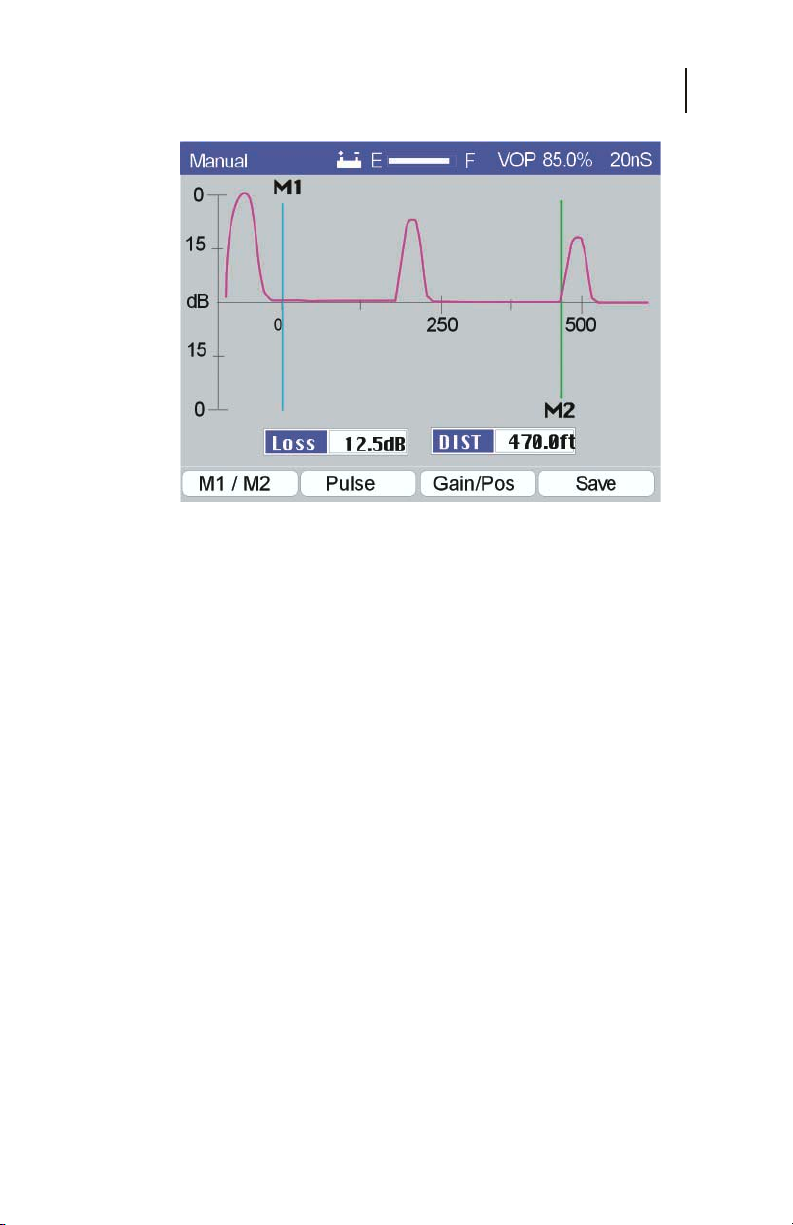
Manual test screen is displayed (Figure 3-13). The tested cable
VOP is shown in the upper right corner. The Pulse Width,
Horizontal Gain and Position, Vertical Gain and Markers are all
set automatically, but may be manually controlled by the user
with the function and arrow keys.
Page 42
Chapter 3
Measurements
Figure 3-13
Although multiple faults may be present and found on the cable
under test, the CE4000 will automatically go to the first cable
fault, place the marker at that location and display the distance
to the fault. The best practice is always to repair the first fault and
retest. This is because the first reflection reduces the energy
delivered to the second fault and prevents an accurate
measurement of the return loss at subsequent faults.
43
Auto is the fastest and most accurate mode of operation.
Under microprocessor control, the CE4000 can sequence
through the various TDR settings very quickly and provide
the best display of the test results. Since the Auto test results
are calculated based on the raw test data, the accuracy is not
subject to the limitations of the display resolution, as with
most TDRs.
DISPLAY
The CE4000 color display provides comprehensive
information and measurement details.
Top Bar - The top bar provides basic unit information,
including the current test mode “Manual”. The battery
icon indicates the unit is operating from battery power,
the bar graph indicates the battery charge condition
(full), the VOP (85.0%) used for the test and the Pulse
Width (20 nSec).
Page 43

CE4000 Cable Explorer TDR
44
User Manual
Axes - The horizontal and vertical axes depict the
distance to the fault and the severity of the fault in dB
of Return Loss. The scale of the axes is dependent on
automatic or manual settings with the numeric values
shown with calibrated tic mark locations.
Markers - Two markers are provided and automatically
placed. The Loss and DIST measurements are made at
the markers. Arrow keys can be used to move the
markers.
DIST - Distance is the measurement of the cable’s
distance from the TDR to the reflection from the fault.
Loss - The Loss is the measurement of the Return Loss
at the fault plus two times the cable loss over the
distance from the TDR to the fault.
The TDR displays the distance measurement both on the
horizontal scale and digitally for the placement of the M2
marker. M1 is automatically placed at the beginning of the cable
under test and M2 is placed at the point of the reflection (fault).
The loss at the point of the reflection is also displayed, indicating
the return loss of the reflection—or the ratio of the level of the
reflection to the level of the incidence pulse in dB. The vertical
scale is logarithmic, with level marks, also indicating the ratio of
the reflected pulse to the incidence pulse.
Function Keys - At the bottom of the display are additional
function keys, M1/M2 (F1), Pulse Width (F2), H Pos/Gain (F3)
and Save (F4). These may be used to further investigate the
results of the TDR display.
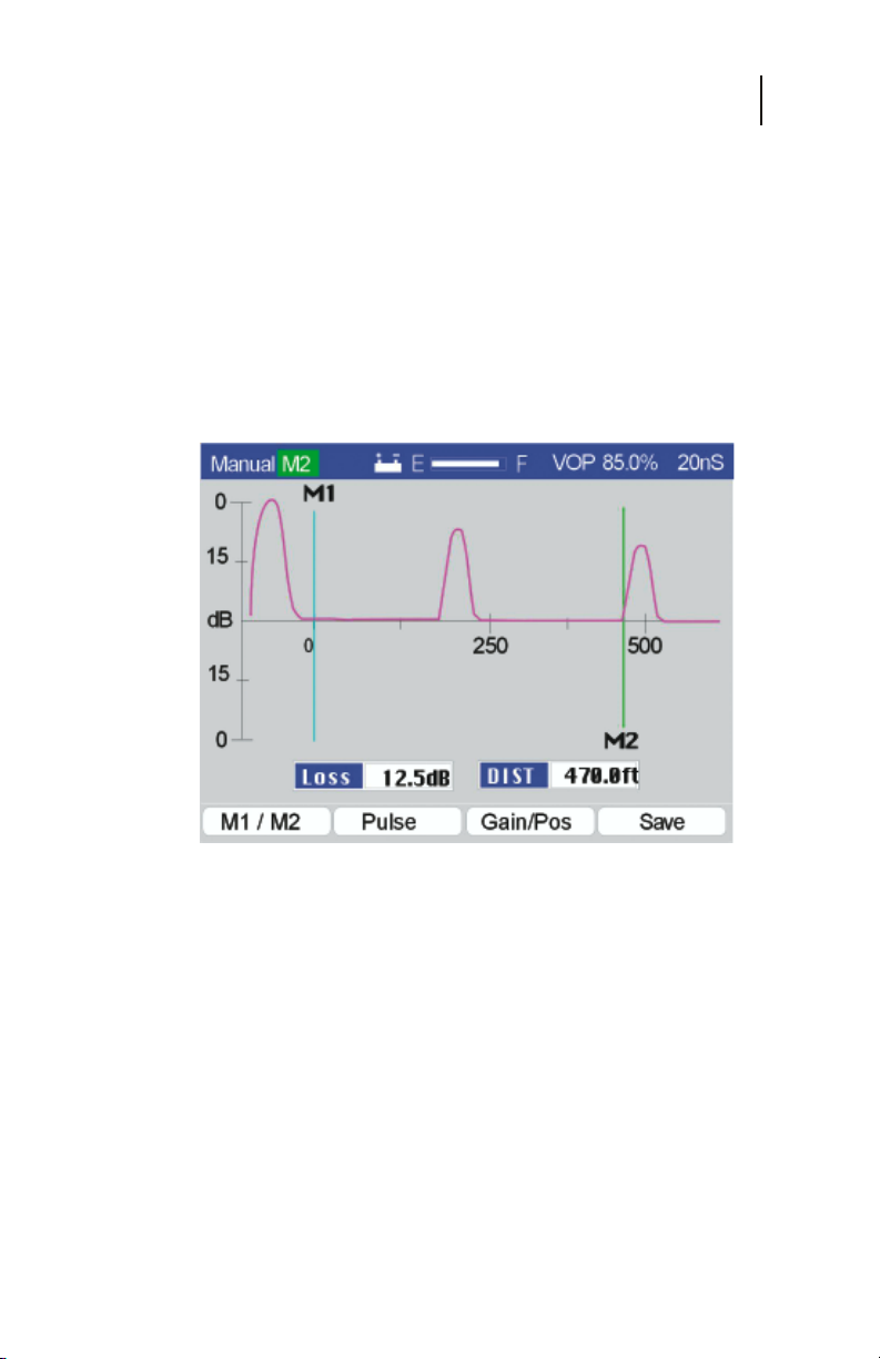
M1/M2
The M1/M2 (F1) function will sequence the Left and Right
arrows between controlling the M1 marker, the M2 marker, both
markers and turning off both markers. The selected marker is
indicated at the top left of the display next to the screen name and
is highlighted with a green background.
Use the Left and Right Arrow keys to move the selected marker.
The marker may be moved one pixel at a time with one press of
the button, or the button may be held down, causing the marker
to sequentially move in larger increments.
Page 44
Chapter 3
Measurements
Distance measurements are made at the beginning of the
reflection pulse. Position the marker at the point on the TDR
trace where the pulse rises quickly. The measured distance
will be displayed in the DIST box on the screen.
Loss is measured in the same fashion. The actual loss
measurement is made at the peak of the pulse automatically
when the marker is placed on the rising edge of the pulse. Thus,
the distance and the loss are made from a single marker position.
The loss measurement window is roughly as wide as the reflected
pulse displayed on the screen.
45
Figure 3-14
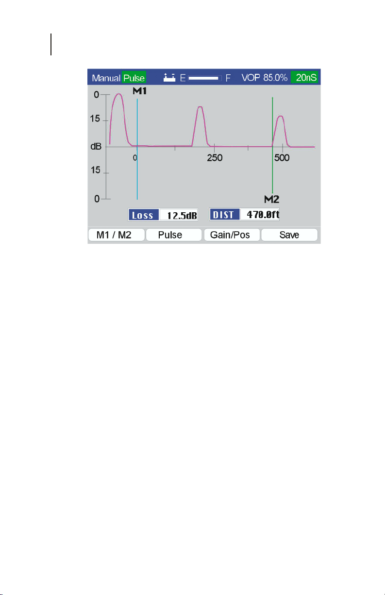
PULSE
The Pulse Width (F2) function key permits using the Left and
Right Arrow keys to sequence through the available pulse
widths of the CE4000. Pulse widths of 10 nSec, 20 nSec, 50
nSec, 100 nSec, 200 nSec and 350 nSec are available.
The right arrow key increases the pulse width, while the left
arrow key decreases the pulse width. A new trace is provided
when the pulse width is changed (Figure 3-15).
Longer pulse widths allow you to test longer cables and to view
higher return losses. Since they provide more energy in the
incidence pulse, more energy is reflected by the fault and
detectable for display.
Page 45
CE4000 Cable Explorer TDR
46
User Manual
Figure 3-15
GAIN / POS
The Gain/Pos (F3) function key toggles the Left and Right arrow
keys to control the horizontal position and range on the CE4000
display. Pressing the Gain/Pos (F3) key once will display Gain
next to the screen name (upper left portion of the screen),
highlighted by a green background (Figure 3-16), and will allow
the Right and Left arrow keys to sequence through the horizontal
gain ranges. The CE4000 full scale ranges are 100, 250, 500,
1300, 2700 and 5500 feet or 30, 76, 152, 396, 822 and 1676
meters.
Pressing the Gain/Pos (F3) key a second time will display “Pos”
next to the screen name (upper left portion of the screen),
highlighted by a green background (Figure 3-17), and will allow
the Right and Left arrow keys to slide the horizontal scale to the
left or right on the display increasing or decreasing the full scale
value, but not changing the range. POS allows the user to reposition the trace on the display.
Page 46
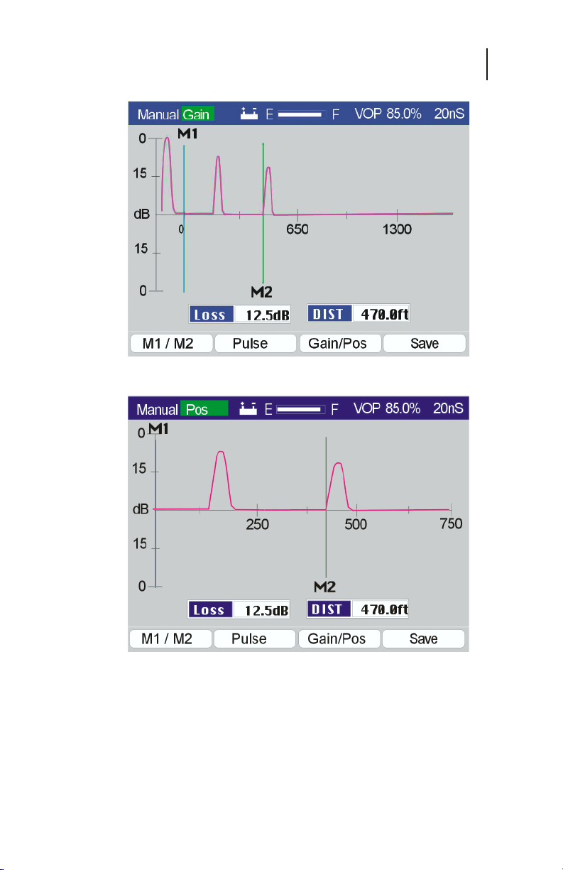
Figure 3-16
Chapter 3
Measurements
47
Figure 3-17
Using a combination of Gain and Pos, the user can expand the
horizontal resolution and view any distance on the horizontal
scale.
Page 47
CE4000 Cable Explorer TDR
48
User Manual
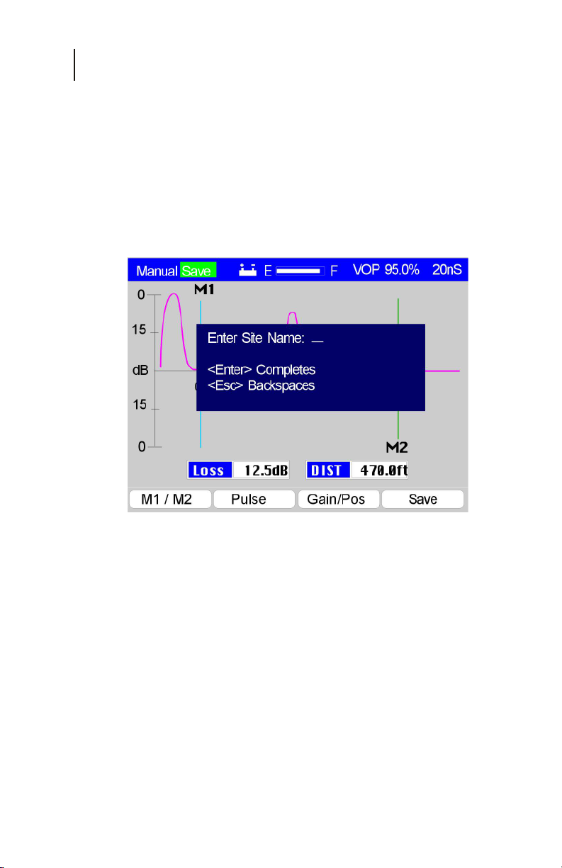
SAVE - The Save (F4) function key freezes the current
screen and permits the entry of a Site Name for the
screen to be stored (Figure 3-18). Up to 10 characters
may be entered to describe the screen data. Use the
alphanumeric keys to enter the information. Press ESC
to back up one space if the wrong character is entered.
Press Enter when the desired Site Name is displayed.
The type of display, date and time will be saved
automatically along with the data.
Figure 3-18
Page 48
STORED FILES
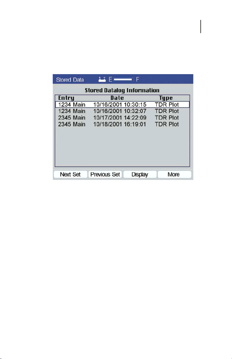
Screens that have been saved may be recalled to the display
through the Stored Data icon on the Main Menu.
Figure 3-19
Chapter 3
Measurements
49
Highlight the Stored Files icon from the Main Menu using the
arrow keys and press Enter (F4). The Stored Files screen will be
displayed as shown in Figure 3-19.
The display lists the Stored Data Log information that has been
stored using the Save functions in the Manual or Automatic
measurements modes. The information listed is the site name
that the user entered for the screen when it was saved, the date
and time and type of screen that were stored. The list is sorted by
the date and time, most recent listed first. Screens may be
selected using the arrow keys to highlight the data and pressing
the Display (F3) key. Approximately 50 screens may be saved.
As shown in figure 3-19, the user is offered the functions: Next
Set, Prev Set, Display and More.
Next Set – With Next Set (F1) allows the user to scroll
a page at a time—Page Down.
Page 49
CE4000 Cable Explorer TDR
50
User Manual
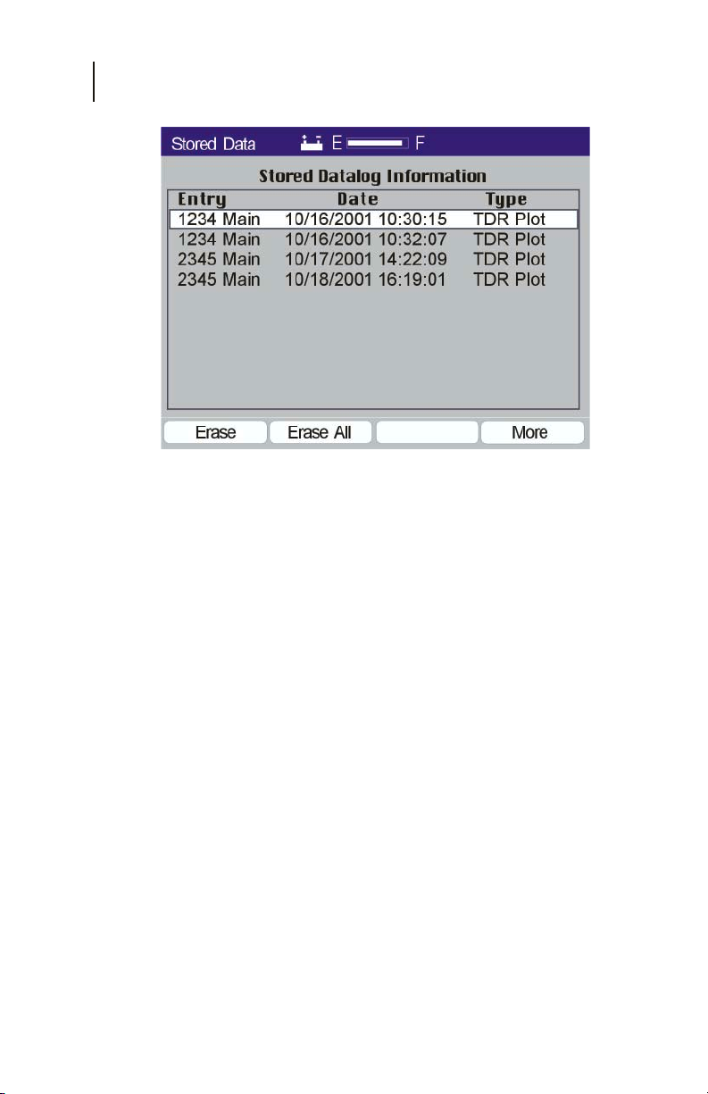
Figure 3-20
Prev Set - Previous Set (F2) allows the user to scroll
backward a page at a time—Page Up.
Display - Recalls the stored screen to the display.
More - Provides the user with additional functions:
Erase, Erase All and More (Figure 3-20).
Erase - Erase (F1) clears the currently selected set
of data from the file.
Note: No warning is provided and recovery is not possible.
Once the ERASE (F1) key is pressed the data is lost.
Erase All - Erase All (F2) clears all of data from
the files.
Note: No warning is provided and recovery is not possible.
Once the ERASE ALL (F2) key is pressed the data
is lost.
More - More (F4) wraps back to the original list of
functions.
When the user selects a Stored File by pressing the Display (F3)
function key, the TDR screen is displayed, just as it was stored.
When the screen was saved, the data which produced the test
results was stored, not just a bitmap image. Thus, additional
Page 50
Chapter 3
Measurements
views of the data are available by pressing the Nest (F1) function
key to display the next fault or the Adjust (F2) function key to
adjust the vertical gain or horizontal gain (range).
Two stored files may be compared by pressing the Compare (F3)
function key and selecting a second saved file.
DISPLAY CONTROLS
The Up and Down arrow keys adjust the vertical gain. Increasing
the vertical gain shows smaller reflections from faults (higher
return loss). The Left or Right arrow keys adjust the horizontal
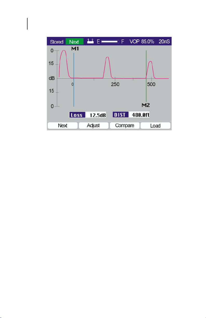
gain (range) of the display as shown in Figure 3-21. In comparing
Figure 3-21 to Figure 3-22, notice that the horizontal scale has
increased from 250 to 500, showing a second fault at 480.
51
Figure 3-21
NEXT
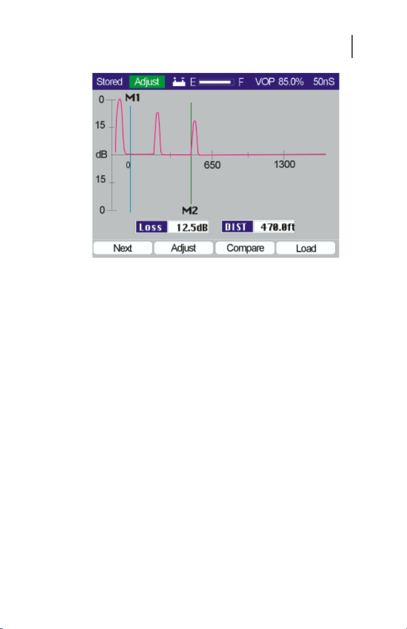
The Next (F1) function will sequence the CE4000’s Auto test
mode from the first fault to any subsequent faults on the cable
under test (Figure 3-22).
The marker is set automatically to the next reflection fault, the
vertical and horizontal scales are adjusted and the measurements
are displayed. If no faults are found, the CE4000 will display a
message over the TDR screen, which indicates: “No Faults“ and
the range of the TDR test. Once “No Faults” is found, the TDR
will wrap back around to the original test screen displaying the
first fault.
Page 51
CE4000 Cable Explorer TDR
52
User Manual
Figure 3-22
ADJUST
The Adjust (F2) function allows adjustment of the Pulse Width
using the Up/Down arrow keys, as shown in Figure 3-23.
Typically two pulse widths will be stored automatically,
depending on the mode and length of cable under test. Only
Pulse Widths stored may be viewed. After pressing the Adjust
(F2) function key you may also press the Left/Right arrow keys
to adjust the position of the second marker M2. As in the Manual
operating mode, the digital display measures the Distance and
Loss relative to the placement of the M2 marker. The correct
placement for distance measurements is at the beginning of the
rising edge of the reflected trace. The Loss measurement is made
automatically 1/2 the distance of the pulse width to the right of
the marker placement. Pressing the Adjust (F2) key again will
turn the adjust mode off.
Page 52
Chapter 3
Measurements
Figure 3-23
COMPARE
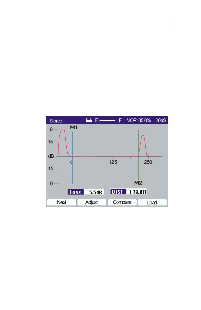
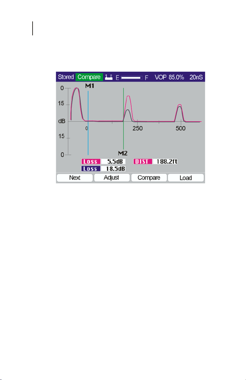
The Compare (F3) function key displays a Stored Data screen,
(Figure 3-19), prompting the user to select a second saved screen
to display. The first and second screens will be displayed
simultaneously, the first in the normal Plot 1 color and the
second in the Plot 2 color, as selected in the Setup screens. See
the Setup section for details of selecting trace colors. A sample
Compare display is shown in Figure 3-24, displaying two traces
of the same cable with an intermittent fault shown at 170 feet.
The first trace shows a loss of only 5.5 dB (a very poor return
loss) and the second trace shows a return loss of 18.5 dB (much
better), thus indicating that a problem such as a loose or corroded
connecter likely exists at 188 feet down the cable under test.
53
Next and Adjust provide the same functions in the Compare
mode as in the normal Single Trace mode. Next will display the
next cable fault. Adjust will allow you to adjust the vertical and
horizontal scale.
Page 53
CE4000 Cable Explorer TDR
54
User Manual
LOAD
Load returns the user to the Stored Data screen (Figure 3-19), to
select another saved screen to display.
Figure 3-24
Page 54

Chapter 4
Specifications
53
Chapter 4
Specifications
PERFORMANCE SPECIFICATIONS AND KEY FEATURES
Horizontal Resolution
<2000 ft: at .99 VOP 0.25 ft
>2000 ft: at any VOP 1.00 ft
Vertical Resolution
Bits 14
Pixels 140
Vertical Sensitivity: 62 dB
Range
Maximum All VOPs 4000 ft
Dead Zone 0 ft
Distance Accuracy: ± .1ft ±.01%
Input Protection
DC to 400 Hz 400 V
>1 MHz 10 V
Measurements
Loss Measurement accuracy ±2 dB
VOP 0.01
Velocity of Propagation: .300 to .990 or 30.0% to 99.0%
Increments. 0.001 or .1%
Pulse Widths 10, 20, 50, 100, 200, 350
Waveform Storage
Full resolution
Standard: 25
Automatic Noise Filter
Power filters 50 & 60 Hz
Cable VOP Database
Pre-Programmed Database ~50 Common Cables
Cable Loss Compensation
Page 55

CE4000 Cable Explorer TDR
54
User Manual
Environment
Min. Operating temperature: 0˚C
Max. Operating temperature: 50˚C
Humidity: (non-condensing.) 95%
Storage temperature: -4 deg F (-20 C) to
Interfaces
RF Input: 75-ohm F81 (Do not exceed 90V AC/DC or
10V > 1 MHz)
RS232 serial port (DB9 female)
RJ-45 Ethernet 10/100Base-T
Power
Internal: NiMH battery pack, part number:
ASY-12183-010
Operating time: 3 hours continuous (typical)
Automatic low battery shutdown
Charger Input: Min. 15.5VDC 2.5A— Max 18VDC 2.8A
Display
Color Active Matrix LCD 320 x 240
Backlight—Programmable Auto Off
+140 deg F (+60 C)
Physical
Size: 11” high x 5” wide x 2-3/4” deep
Weight: 3 lbs.
Operating Temperature Range: 0˚C to 50˚C
(32˚F to 122˚F)
Page 56
Maintenance and Service
Chapter 5
55
Chapter 5
Maintenance And Service
INTRODUCTION
This section contains information on maintenance and service
for the CM1000 Cable Modem Analyzer.
Battery Replacement
The CM1000 uses a user-replaceable nickel metal hydride
battery. Battery replacements are available from Sunrise. The
use of batteries other than those specifically approved may
damage the test equipment and will void the warranty.
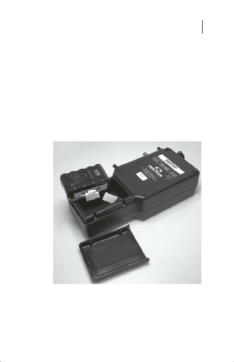
Figure 5-1
The battery is easily replaced by removing four screws located
in the lower portion of the unit’s rear panel. The part number for
the replacement battery is ASY-12183-010.
Page 57

CE4000 Cable Explorer TDR
56
User Manual
GENERAL MAINTENANCE
Internal Rechargeable Battery
To avoid damaging the internal battery, optimize its life and
guarantee a full charge in 6-8 hours, the following steps should
be followed:
• Let the CM1000 cool to room temperature before
recharging.
• Turn the CM1000 OFF before plugging in the
charger.
• Leave the CM1000 OFF while recharging.
• Always leave the charger connected whenever the
CM1000 is not in use.
PRECAUTION: Do not charge the CM1000 above room temperature
NOTE: Use only the supplied AC adapter or the optional DC
or with the unit turned ON. The internal battery may
be
hot
, or can become
significantly increasing the time required to fully
charge the battery.
adapter to recharge the CM1000. Incorrect polarity or
voltage could damage the CM1000 or its internal
battery.
hot
, reducing its life and
Cleaning
Clean the CM1000 with a soft cloth moistened with water. Use
a small amount of mild soap if necessary. Do not apply abrasive
or chemical cleaners. These may damage the plastic finishes on
the case, keypad, or display windows.
Page 58

TROUBLESHOOTING
If the CM1000 fails to operate and no front panel indicators are
illuminated, the internal nickel metal hydride battery may be
discharged. Use the supplied AC adapter to power the unit and
recharge the battery. If the failure persists while using the AC
adapter, call Sunrise for service.
If the internal battery fails to recharge, verify that the AC
adapter is actually sending power to the CM1000. Plug the
AC adapter into the CE4000 RECHARGE input and then
connect the AC adapter to the 115VAC source. Turn the
CM1000 on to test the battery condition and then back off. If
the internal battery fails to recharge, but the AC adapter
delivers power to the CM1000, the battery may be deeply
discharged or damaged. A deep discharge requires a longer
charge time. If the battery is not restored to normal operation
by an eight-hour recharge (unit off), call Sunrise for service.
Firmware Upgrades
Firmware upgrades may be downloaded from the Sunrise web
site at www.sunrisetelecom.com. Complete instructions are
provided at the web site.
Maintenance and Service
Chapter 5
57
CompactFlash Card Replacement
The CE4000 utilizes a removable CompactFlash card for future
expansions and/or firmware upgrades.
Before removing the CompactFlash card, be sure that the
CM1000 is off.
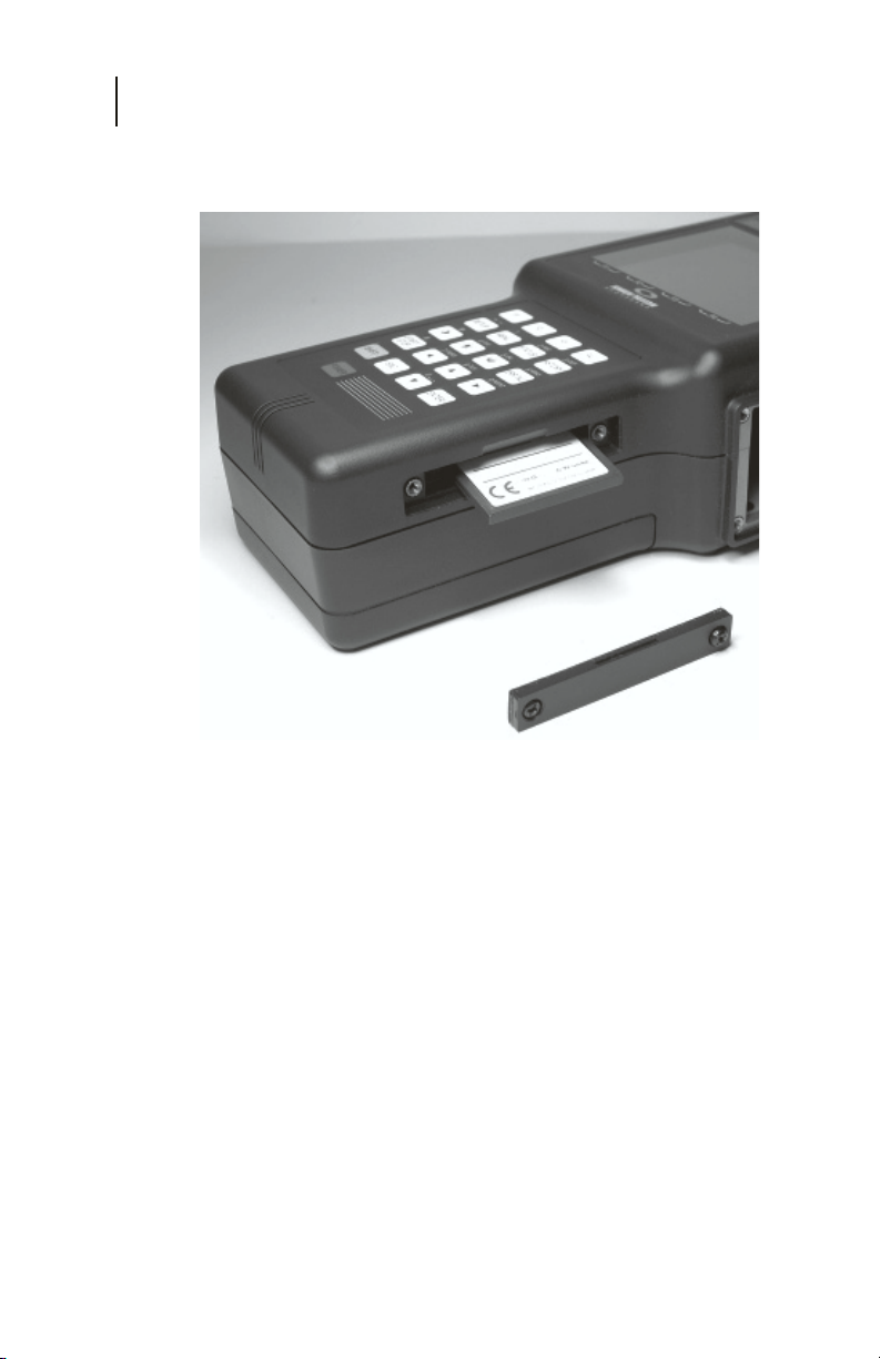
Set the unit on its side on a flat surface with the plug-in module
slot facing upward and the keypad facing you. The memory card
slot is located on the side of the unit just to the right of the keypad
and is protected by a small cover held in place by two Phillips
head screws. Remove the two Phillips head screws and the
protective cover. The memory card will be visible in the slot. A
small rectangular shaped button to right of the memory card will
also be visible. Press this button to eject the memory card from
its slot and then pull the card out of the slot (a pair of tweezers
or needle nose pliers may be helpful).
Page 59
CE4000 Cable Explorer TDR
58
User Manual
Insert the new memory card and press it firmly but gently into the
slot. Replace the protective cover. Powering the unit on will
automatically load the new software into the CM1000. This
process may take several minutes depending on the software
being loaded. The Link LED will flash green during the software
update process.
Be sure to seat the memory card fully and tighten the access
cover screws.
Note: The CompactFlash card installs with the Sunrise
label facing down.
Page 60

TECHNICAL SUPPORT
Sunrise is located in the Eastern Time zone with regular office
hours from 8:00AM to 8:00PM. A toll free number service
covering all of North America is provided at no charge. Key
Sunrise personnel can always be reached any time of the day
through a toll free number or electronic mail service over the
Internet.
International customers should contact the nearest Sunrise
Representative or the factory at 1-725-6652 or by fax at 1-514725-5637
North America Toll Free: 1-800-297-9726
Outside of North America: 1-514-725-6652
E-mail address for Technical Support:
website: www.sunrisetelecom.com
WARRANTY
Sunrise warrants the CE4000 Cable Explorer TDR module
against defects in materials and workmanship for a period of one
year from receipt by the customer. During the warranty period,
Sunrise will, at its option, repair or replace defective products.
Maintenance and Service
Chapter 5
59
Liability under this warranty extends only to the replacement
value of the equipment.
This warranty does not apply under the following conditions:
The CE4000 has been partially or fully disassembled,
altered or repaired by persons not authorized by Sunrise.
The CE4000 is installed or operated other than in
accordance with instructions contained in its operating
manual.
No other warranty is expressed or implied. Sunrise is not liable
for consequential damages.
Page 61

CE4000 Cable Explorer TDR
60
User Manual
RETURNING EQUIPMENT TO SUNRISE
Sunrise manufactures equipment to very high standards. Products
are warranted against defects in materials and workmanship, as
specified in our published product warranty. When properly
used and operated, your equipment will provide many years of
service. Should it become necessary to return the, equipment to
Sunrise for in or out of warranty repairs or calibration, the
following steps should be followed.
Note: If products are repaired or altered by persons not
authorized by Sunrise, or not in accordance with
instructions furnished by Sunrise or if the products
have become defective due to a result of misuse,
improper repair, abnormal operating conditions, the
labor and materials required to effect the changes
will be billed at our standard repair rates.
Customer’s Responsibility
1. Contact Sunrise and request a Returned Material
Authorization (RMA) number. Be sure to have your
model and serial number ready.
2. After receiving the RMA number, return the
equipment with an accurate description of the
symptoms and be sure to state the authorization
number on your paperwork. The client is responsible
for all transportation charges to Sunrise.
3. Original packaging is preferred. If unavailable,
carefully package the equipment in alternate packing
material to ensure adequate protection during
shipping.
Sunrise’s Responsibility
1. Sunrise will acknowledge the receipt of the
returned equipment and at that time bring any
discrepancies to your attention.
2. Sunrise will replace or repair, at its discretion, any
component or sub-assembly it deems necessary to
return the unit to a proper condition.
3. After the necessary repairs, Sunrise will perform
complete test and re-calibration of the unit.
Page 62

Maintenance and Service
Chapter 5
All precautions are taken by Sunrise to ensure that every unit
meets all electrical and mechanical specifications prior to
returning the equipment to the client.
Note: Sunrise is not responsible for failures caused by
transportation to/from the customer’s location, nor
by rough handling by the customer after receipt
causing further damage to the product. Sunrise is
solely responsible for the defects stated above and
in our standard product warranty policy.
If you require information or assistance, contact SunriseTelecom
Broadband at 1-800-297-9726 toll free from anywhere in
North America or by fax 1-514-725-5637 or by e-mail to:
[email protected].
61
Page 63

CE4000 Cable Explorer TDR
62
User Manual
Page 64

Chapter 6 Appendix
Additional Cable data
Appendix: Cable Data
Chapter 6
63
Cable Type Cable Manufacturer VOP
Cable
Loss
Page 65

CE4000 Cable Explorer TDR
yp
64
User Manual
e
Cable T
P3-412 Comscope 87.0% 2.65 dB
P3-500 Comscope 87.0% 2.04 dB
P3-565 Comscope 89.0% 1.78 dB
P3-625 Comscope 87.0% 1.66 dB
P3-700 Comscope 89.0% 1.44 dB
P3-750 Comscope 87.0% 1.38 dB
P3-840 Comscope 89.0% 1.26 dB
P3-875 Comscope 87.0% 1.21 dB
P3-1000 Comscope 87.0% 1.21 dB
QR-540 Comscope 88.0% 1.80 dB
QR-715 Comscope 88.0% 1.36 dB
QR-860 Comscope 88.0% 1.17 dB
QR-1125 Comscope 88.0% 0.93 dB
MDU-320 Comscope 87.0% 3.15 dB
F59 Comscope 85.0% 6.97 dB
F6 Comscope 85.0% 5.65 dB
F7 Comscope 85.0% 4.57 dB
F11 Comscope 85.0% 3.65 dB
MC.440 Trilogy 93.0% 2.13 dB
MC.500 Trilogy 93.0% 1.83 dB
MC.650 Trilogy 93.0% 1.50 dB
MC.750 Trilogy 93.0% 1.25 dB
MC1.00 Trilogy 93.0% 0.97 dB
MVP-59 Trilogy 85.0% 7.34 dB
MVP-6 Trilogy 85.0% 5.76 dB
MVP-7 Trilogy 85.0% 4.64 dB
MVP-11 Trilogy 85.0% 3.79 dB
T10-412 Times Fiber 87.0% 2.68 dB
T10-500 Times Fiber 87.0% 2.16 dB
T10-625 Times Fiber 87.0% 1.79 dB
T10-750 Times Fiber 87.0% 1.48 dB
T10-875 Times Fiber 87.0% 1.29 dB
T10-1000 Times Fiber 87.0% 1.21 dB
TX10-565 Times Fiber 89.0% 1.85 dB
TX10-700 Times Fiber 89.0% 1.49 dB
TX10-840 Times Fiber 89.0% 1.30 dB
TX10-1160 Times Fiber 89.0% 1.01 dB
SPC-625 Times Fiber 87.0% 1.82 dB
T10 RG-59 Times Fiber 85.0% 6.96 dB
T10 RG-6 Times Fiber 85.0% 5.62 dB
T10 RG-7 Times Fiber 85.0% 4.50 dB
T10 RF-11 Times Fiber 85.0% 3.58 dB
TX Flex Times Fiber 88.0% 2.23 dB
Beldon 59 Beldon 82.0% 6.97 dB
Beldon 6 Beldon 82.0% 5.35 dB
Beldon 7 Beldon 82.0% 4.13 dB
Beldon 11 Beldon 82.0% 3.39 dB
Mfg. VOP 750 MHz
Attenuation
 Loading...