

Page 1
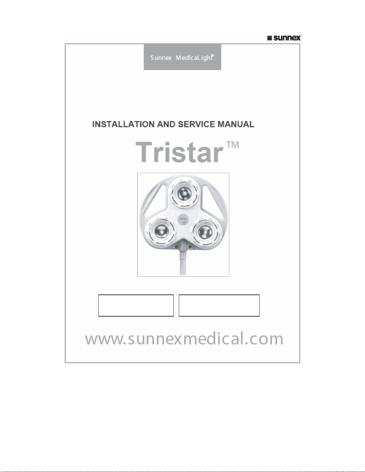
MOBILE
TS2035M, TS2015M
WALL
TS2035W, TS2015W
Page 2

Table of Contents
1. SHIPPING CARTON & CONTENTS.......................................................... 3
2. INTRODUCTION........................................................................................ 4
3. OPERATION.............................................................................................. 5
4. ASSEMBLY OF TRISTAR MOBILE......................................................... 5
5. ASSEMBLY AND INSTALLATION OF TRISTAR WALL.......................... 5
6. ABOUT YOUR TRISTAR...........................................................................7
7. CARE FOR YOUR TRISTAR LIGHT......................................................... 8
8. SERVICE AND MAINTENANCE ............................................................... 9
9. WARRANTY............................................................................................. 12
10. TROUBLESHOOTING........................................................................... 13
• SAVE THIS PRODUCT MANUAL
• READ ALL INSTRUCTIONS BEFORE ASSEMBLY AND USE
• IF YOU DON’T UNDERSTAND ANY GUIDELINES IN THIS MANUAL, CALL
DISTRIBUTOR OR MANUFACTURER
• DO NOT USE THIS LIGHT IF IT IS DAMAGED, BROKEN, OR HAS MISSING
PARTS
Sunnex Tristar Service & Installation Manual
2
Page 3

1. SHIPPING CARTON & CONTENTS
TS2015M / TS2035M
• The 14” (35cm) base
• The Hand-Ez upright column
• The lamp head and Dual/Flex arm
• A four-wing wire frame with casters assembled
TS2015W / TS2035W
• Wall board with Tee Nuts and “U” mounting bracket
• Wall extension arm 30” (75cm)
• The lamp head with the balance arm
• 2 X (1/4”-20) socket cap screws for attaching wall extension arm to wall
board
• Plastic washers (Two)
• Allen wrench (5/32)
CAREFULLY CHECK THE CONTENTS OF THE SHIPMENT. REPORT SHORTAGES
AND/OR ERRORS, TO SUNNEX OR YOUR DEALER’S CUSTOMER SERVICE
DEPARTMENT, WITHIN FIVE (5) WORKING DAYS.
THE RECOVERY OF COSTS RELATED TO SHIPPING DAMAGE, CONCEALED OR
OTHERWISE, CAN BE A LONG AND FRUSTRATING EXPERIENCE. IN ORDER TO
AVOID THE UNCOMFORTABLE ASPECTS, ALL FREIGHT CLAIMS BY EITHER THE
DEALER OR CONSIGNEE SHOULD BE FILED WITH THE TRANSPORTATION
COMPANY WITHIN FIVE (5) WORKING DAYS. THE CARTON AND ITS INSERTS
SHOULD BE KEPT FOR INSPECTION BY THE TRANSPORTATION COMPANY.
CAUTION: PLEASE BE AWARE, IF THIS ROUTINE IS NOT FOLLOWED, AND THE
CARTON AND ITS CONTENTS ARE DISPOSED OF OR DESTROYED BEFORE
INSPECTION BY THE TRANSPORTATION
COMPANY, OUR ASSISTANCE IS OF NO VALUE TO YOU.
2. INTRODUCTION
The objective of this manual is to assist you in assembling your TRISTAR
light, and, to familiarize you to it’s more important features. Some
suggestions for its care are also included.
CAUTION: IF A WALL DIMMER IS USED WITH THE LIGHT, IT VOIDS
CERTIFICATION LISTING OF THE PRODUCT. NO DIMMERS ARE APPROVED
TO BE USED WITH THIS LIGHT.
Sunnex Tristar Service & Installation Manual
3
Page 4

2.1 APPLICATIONS
The Sunnex Tristar offers an economical alternative to traditional minor
surgical and examination lights.
2.2 TECHNICAL DATA
This light is certified according to the following standards:
CAN/CSA-C22.2 No. 601.1-M90
EN 60601-1, UL 60601-1, IEC 60601-2-41
Power Supply: 120V or 230V, 50- 60Hz
Nominal Effect 105VA
Light Intensity: 38,000 Lux @ 1 meter (35 W MODEL) (with UV
filter) *
27,000 Lux @ 1 meter (20 W MODEL) (with UV
filter) *
Light Source: 35 W MODEL: Halogen Bulb –12V/3x35W/10°
20 W MODEL: Halogen Bulb –12V/3x20W/10°
Color temp: 3,000K
Medical Standard: Class II Listing
Weight: 25 lbs (Mobile)
20.4 lbs (Wall)
* 46,000 Lux at 1 meter available without UV filter for 35 W MODEL
This product is rated as a Class II device, mode of operations is
suited for continuous use
Radiated and conducted emissions testing has been completed
on the TS2015 series lights and for compliance with IEC 60601-1-2
(2001-09) 2
nd
edition (EN55011:1991, Group I Class B)
2.3 TRANSPORTATION AND STORAGE
The light is packaged in card board and should be transported protected from
moisture. The light should be stored in a dry environment and room
temperature.
Transportation and storage temperature: -5°F to 140°F
Humidity < 95%
3. OPERATION
Sunnex Tristar Service & Installation Manual
4
Page 5

Plug the three prong molded plug into an appropriate Hospital Grade
receptacle. Power-on your light via the rocker switch in the back cover of the
lamp head. The TRI*STAR is powered by a 105W isolation, step-down
transformer, that contains an internal thermal cutoff for your added safety.
The transformer steps down ordinary wall current to allow for activation of the
three lamp reflectors.
4. ASSEMBLY OF TRISTAR MOBILE
Remove the Hand-Ez upright column and the lamp head assembly from the
shipping carton.
Insert the bottom of upright column and screw the upright column into the
base. Mount the screw with washer to the bottom of pole, using Allen wrench
(provided).
Attaching the lamp head assembly is a simple procedure. Raise the metal
collar of the connector, and slip the assembly onto the standoff on top of the
Hand-Ez upright column. Once in place, push down on the metal collar to
properly seat the connection. CAUTION: IF YOU DO NOT FEEL A
POSITIVE SEATING, PROPER CONNECTION HAS NOT BEEN
ACCOMPLISHED. CHECK AGAIN TO ENSURE YOU HAVE SECURELY
CONNECTED THE LAMP HEAD ASSEMBLY TO THE UPRIGHT COLUMN.
Next, place the wire frame/caster assembly on the floor or a flat surface.
Position the cast iron base within the wire frame. It should be captured by the
three (3) wings. Grasp the fourth (4th.) wing. While gently pulling outward,
push down on the surface of the iron base. It should SNAP DOWN AND
NOW SEAT WITHIN THE GRASP OF ALL FOUR (4) WINGS. Roll the base
around to ensure the base is properly seated and the light rolls easily.
5. ASSEMBLY AND INSTALLATION OF TRISTAR WALL
Your shipping carton will contain a lamp head and flex arm, an extension
arm, Melamine covered wall board (24” W X 16” L X 0.78” THK OR 610mm
W X 407mm L X 20mm THK) with U-bracket and transformer enclosure
mounted on the board, and four (4) plastic fasteners to capture the power
cord on the underside of the arm. Surface mounting lag bolts are not
supplied. These should be purchased to meet local codes, and to ensure
they are appropriate for your particular mounting surface.
There are several factors involved with proper installation. Considering them
will help you produce a safe work environment for you and your patients.
Sunnex Tristar Service & Installation Manual
5
Page 6
1. The length of the board has been chosen so that two wooden wall
studs may be engaged during installation.
2. The wooden wall studs or surface holding the mounting board and the
four (4) lag bolts, SHOULD SUPPORT A MINIMUM OF 100 POUNDS
PULL ON EACH MOUNTING BOLT, AND A MINIMUM OF 100 SHEAR
ON EACH BOLT.
3. Use no smaller than 1/2” lag bolts. The bolts should penetrate the
wooden wall studs to at least a depth of 2 1/2”.
The pilot holes should be drilled beyond full depth to ensure the lag bolts are
not broken off during installation. These MINIMUM REQUIREMENTS are
called for in order to support loads applied each time the beam is adjusted.
CAUTION: IF METAL WALL STUDS ARE A PART OF YOUR FACILITY
CONSTRUCTION, ADDITIONAL STEPS MUST BE TAKEN TO ENSURE
THE LIGHT IS SAFELY INSTALLED.
WARNING! METAL WALL STUDS ARE TOO THIN TO ADEQUATELY
ACCEPT AND SECURE LAG BOLTS. ANY ATTEMPT TO DO ONLY THAT
WILL LEAD TO PROBLEMS OF SAFETY WHICH MAY INCLUDE THE
LIGHT FALLING FROM THE WALL.
ATTACHMENT OF LAMP HEAD/ARM/ASSEMBLY:
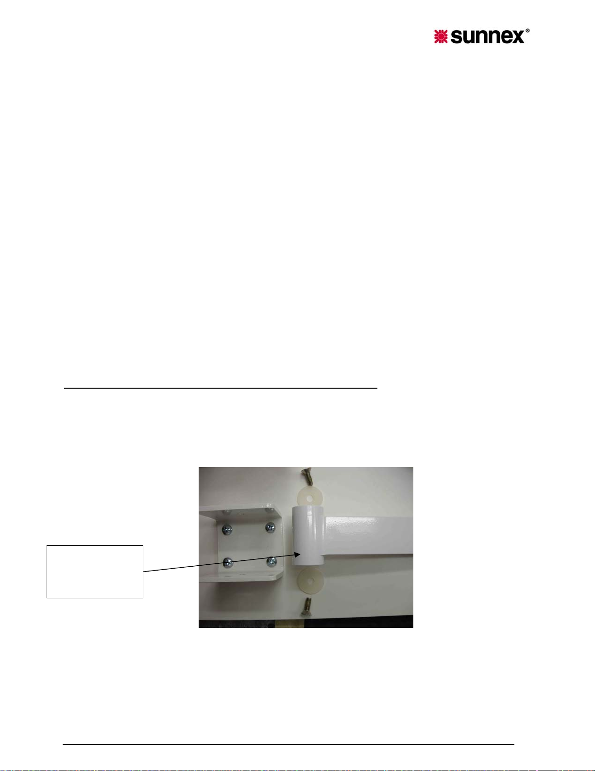
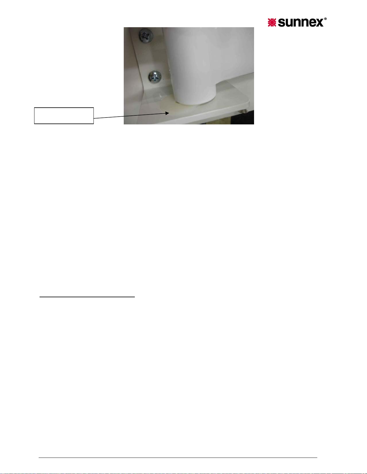
1. Attaching extension arm to wall board: Place the end of the extension
arm inside U-bracket and place plastic washers so that washers are
between U-bracket and end of arm. Secure arm end to U-bracket with
socket cap screws (2 X 1/4”-20), use provided Allen key (5/32). (See
following illustrations).
END OF
EXTENSION
ARM
Sunnex Tristar Service & Installation Manual
6
Page 7
WASHER
2. Raise the metal QUIK-CONNECT collar at the base of the DUAL/FLEX
arm, and slip the assembly onto the standoff on top of the wall
extension arm. Once in place, push down on the collar to properly seat
the connection. CAUTION! IF YOU DO NOT EITHER HEAR IT SNAP
INTO PLACE OR FEEL A POSITIVE SEATING, PROPER
CONNECTION HAS NOT BEEN ACCOMPLISHED. CHECK AGAIN
TO ENSURE YOU HAVE SECURELY CONNECTED THE LAMP
HEAD/ARM ASSEMBLY TO THE STANDOFF.
3. Fix the lamp head arm cord to the under surface of the arms with the
furnished plastic fasteners.
4. Plug the lamp head cord into the outlet in the transformer enclosure.
5. Plug the three-prong power cord from the transformer enclosure into
the wall outlet.
6. ABOUT YOUR TRISTAR
TRISTAR LAMP HEAD:
The lamp head is constructed of high impact
polycarbonate, which offers certain protection not available with metal
reflector lights. The covers and frame provide a safeguard to the reflectors
encased within their design. Along with good physical and thermal qualities,
polycarbonates offer the added advantage of presenting a level of protection
against possible current leakage. The reward is a lack of heat build-up that is
normally experienced with metal reflectors, thus eliminating the danger of
contact burns from a hot reflector surface.
The lamp head rotates 359 degrees in either direction at the point at which it
attaches to the DUAL/FLEX, vinyl coated arm. The control of its movement is
via the handles built into the lamp head frame. The TRISTAR lamp head has
been designed to accept a Sterilizable handle. Should you desire this option,
order a STERILIZABLE HANDLE & MOUNT ASSEMBLY, COMPLETE, P/N
STHM-2.
Sunnex Tristar Service & Installation Manual
7
Page 8

THE DUAL/FLEX ARM: A vinyl covered 17” flexible positioning arm connects
the lamp head to the Hand-Ez upright column, via a QUIKLOK
CONNECTOR. The arm is engineered to two sections with different degrees
of tension. The lower section has a tenseness which allows for proper
positioning of the lamp head while ensuring the beam does not drift. The
upper section provides a lesser degree of tension to allow you the fine lamp
head adjustments needed for more precise positioning.
LAMP HEAD & DUAL/FLEX ARM MOVEMENT:
The combination of the lamp
head on the DUAL/FLEX arm, the arm on the Hand-Ez Upright column, plus
the unrestricted movement of the DUAL/FLEX arm itself, provides you the
greatest range of lamp head motion and positioning. They adjust to your
requirements, and not you to them.
HAND-EZ UPRIGHT EXTENSION COLUMN
: This uniquely designed column
allows you one hand control of the height of your lamp. Simply squeeze the
control at the top of the column and you can raise or lower the column,
easily. The lamp head DUAL/FLEX positioning arm, connects with an inner
column that extends 32” out of a 31” outer, fixed column. The lamp head and
DUAL/FLEX positioning arm combines with both Hand-Ez columns, to offer
you a range of light positioning from a low of 55”, to a height of 80” and,
anywhere in between.
THE BASE:
The low-profile base provides good support, whether the column
is at full extension or, at its lowest position. And, the 4-caster assembly can
easily be removed, when and if mobility is not desired. CAUTION: THE
TRANSFORMER IS ENCLOSED IN POLYCARBONATE HOUSING. WHILE
THAT HOUSING MAY BE CARED FOR AS COVERED IN THE SECTION
RELATING TO THE CARE OF YOUR LIGHT, ENSURE THAT NO FLUIDS
ARE SPILLED ON IT.
7. CARE FOR YOUR TRISTAR LIGHT
The design of bulb housing is such the ambient heat that builds up in front of
any lamp, is moved up and through the back cover louvers, providing a
cooler and more comfortable work atmosphere for you and your patient. In
addition, that movement of air over each lamp/reflector adds to their longer
and more useful life. While your TRI*STAR has been designed to provide
many hours of professional performance, it will benefit from your periodic
care and concern.
Good physical characteristics of polycarbonate offer other advantages in
combination with our low voltage circuitry; they offer a level of “DOUBLE
INSULATION” against possible current leakage.
Sunnex Tristar Service & Installation Manual
8
Page 9
The covers and frame may be easily cleaned with a soft damp cloth of a mild
soap and water solution or, mineral spirits. Isopropyl alcohol is another
acceptable cleansing agent.
The heat absorbing glass filters offer a protection between the patient and
the lamp/reflectors. They provide you a BARRIER to falling pieces of those
assemblies should they experience a physical failure. In addition, they
contribute to a cooler task site by absorbing certain light rays which could
dissipate into hear when incident on the task. “They can be cleaned with any
commercial glass cleaner. CAUTION! DO NOT USE EXCESSIVE
AMOUNTS OF ANY FLUID AND WHEN CLEANING, DO NOT INTRODUCE
ANY FLUIDS TO THE INSIDE OF THE LAMP HEAD HOUSING.
The metal components of your light are powder coated for long life. They too
can be cleaned with a damp cloth of mild soap and water solution, mineral
spirits or, isopropyl alcohol.
SUGGESTION! Periodically dust the back side louvers to ensure
uninterrupted convection of the ambient air and filtered infrared rays through
them. This arm movement cools three lamp/reflector assemblies, further
extending their useful and effective life. Using a vacuum in a manner similar
to the cleaning of a computer key board, will ensure no internal build-up of
dust or powder.
8. SERVICE AND MAINTENANCE
Other than fuse replacement and bulb replacement, there are no repair
procedures or preventive maintenance requirements for the lamp. Any
repairs to the lamp must be performed by a qualified technician or the lamp
can be returned to the manufacturer for repair.
8.1 BULB REPLACEMENT
Sunnex Tristar Service & Installation Manual
9
Page 10
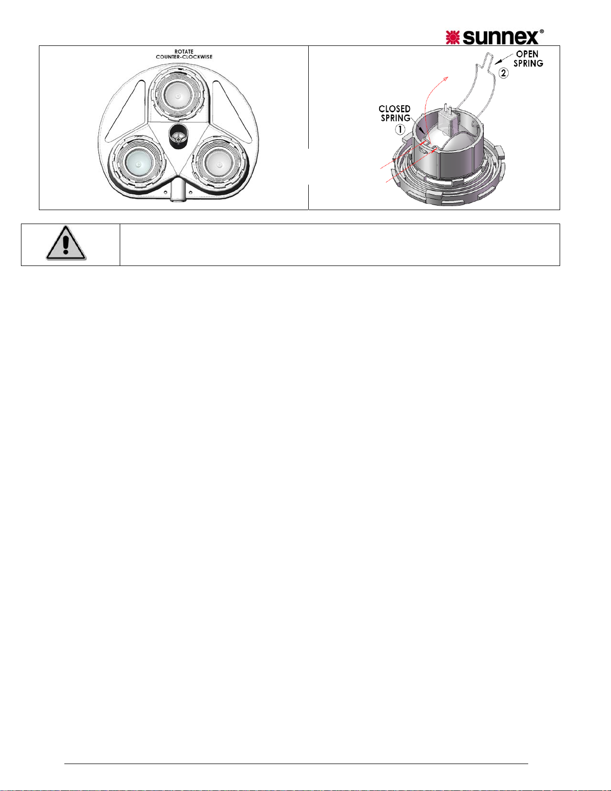
PUSH HERE
TO REMOVE
CAUTION: ONLY USE OSRAM/SYLVANIA TRU-AIM TITAN BULBS, ANY
DEVIATION FROM THE DIRECTIONS MAY SERIOUSLY DAMAGE YOUR
LIGHT. 35W IS MAXIMUM ALLOWED.
When a lamp/reflector burns out, ALLOW SUFFICIENT TIME FOR IT TO
COOL BEFORE ATTEMPTING A REPLACEMENT. Once cool, you should:
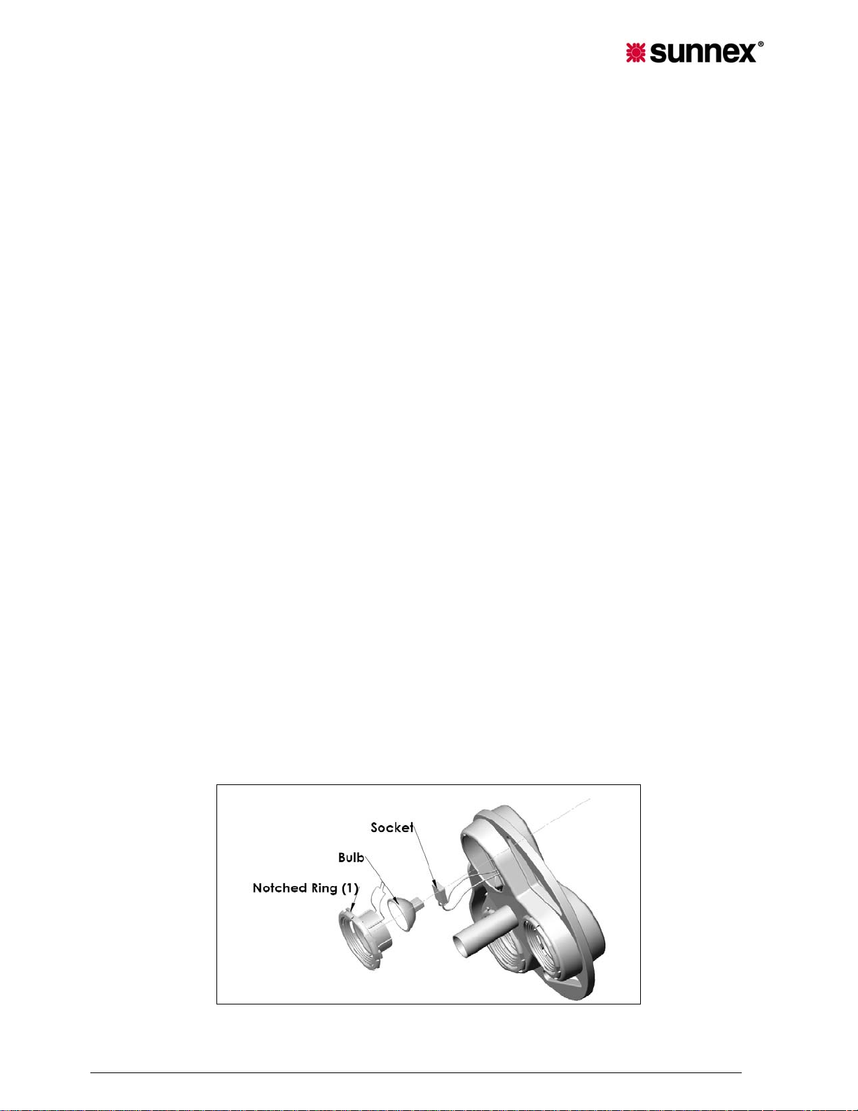
1. Refer to figure. Turn the lamp head over so the three glass
assemblies face upward.
2. With one hand supporting the backside of the lamp, grasp the
notched ring assembly (1) and twist it counter clockwise.
3. Grasp the bulb with one hand and unplug socket connector with the
other.
4. The notched ring assembly may now be removed from the lamp head
and placed face down on a flat surface.
5. Hold the notched ring assembly with thumbs and place two index
fingers at flat part of spring (two red lines in figure 8), pull the spring
towards you pulling it out from the slot (Keep two ends of spring inside
it’s holes)
6. Remove old bulb
7. Install new bulb. Do not touch inside reflector surface of bulb, always
grasp from bulb outside edges
8. Close the retainer spring on the bulb by inserting the front tab of
spring in the slot (using index fingers), so that it fits properly. Check to
ensure proper seating of the spring, by pulling on the bulb. [Position
(1) in figure 8 is “CLOSED SPRING”]. Ensure that two open ends of
spring are properly seated into holes in the notched ring assembly.
9. Reconnect plug socket to bulb.
10. Replace the notched ring assembly in the lamp head by aligning the
three guide projections into the slots on the lamp head. Refer to figure
9. Press gently inward as you twist the assembly clockwise. You will
hit a stop and set in place. Before turning the lamp head over, BE
POSITIVE THE ASSEMBLY IS PROPERLY SEATED by comparing it
with the other two.
Sunnex Tristar Service & Installation Manual
10
Page 11

11. The light is now ready for use.
Only use the following bulbs:
Sunnex part# 18560
3x35W: Sylvania Tru-Aim Titan FRB 35MR16Q/10/NSP/T
3x35W: Osram IRC 35W 10°
CAUTION! A CHOICE OF A REPLACEMENT LAMP/REFLECTOR CAN
AFFECT THE PERFORMANCE OF YOUR TRISTAR LIGHT. WE
STRONGLY SUGGEST THAT ONLY OSRAM/SYLVANIA TRU-AIM TITAN
ESX LAMP/REFLECTORS BE USED. THESE
ARE DESIGNED TO FILTER BOTH INFRARED AND ULTRAVIOLET
RAYS, PROVIDING YOU A CONTINUED SAFE, COOL PERFORMANCE.
THEY PRODUCE A PATTERN WITH A TIGHT CENTER, HARMONIOUS
TO A TEN INCH PERIMETER. INCREASED FRONTAL HEAT AND A
DISTORTED PATTERN ARE BUT A COUPLE OF THE DISADVANTAGES
OF PURCHASING INCORRECT REPLACEMENT LAMP REFLECTORS.
8.2 FUSE REPLACEMENT
1. Remove the plug from wall receptacle.
2. Access the transformer housing and detach the front cover by
removing the four plastic screws using a flat screwdriver.
3. Locate fuse blocks (2) in the transformer.
4. Turn the fuse holder counter clockwise using a suitable tool and
remove the fuse holder from the fuse block by pulling it out.
5. Replace fuse with proper replacement fuse.
Fuse Replacement Specifications:
USA (110V): Buss Fuse – MDA 2 250 Volt OR Interpower 813MDA-2
(250V, 2 Amp Fuse, MUST USE A SLOW-BLOW FUSE
)
Europe (230V): Littlefuse – T-1.25A-218 (250V, 1.25 Amp Fuse,
MUST USE A SLOW-BLOW FUSE
)
6. Follow procedure in reverse to return lamp to operating condition.
The functional earth conductor is not intended for use as a protective
earth (chassis) ground.
For more information on our product, visit our web site at
www.sunnexonline.com
or call us at (800) 445-7869.
SYMBOLS
Sunnex Tristar Service & Installation Manual
11
Page 12
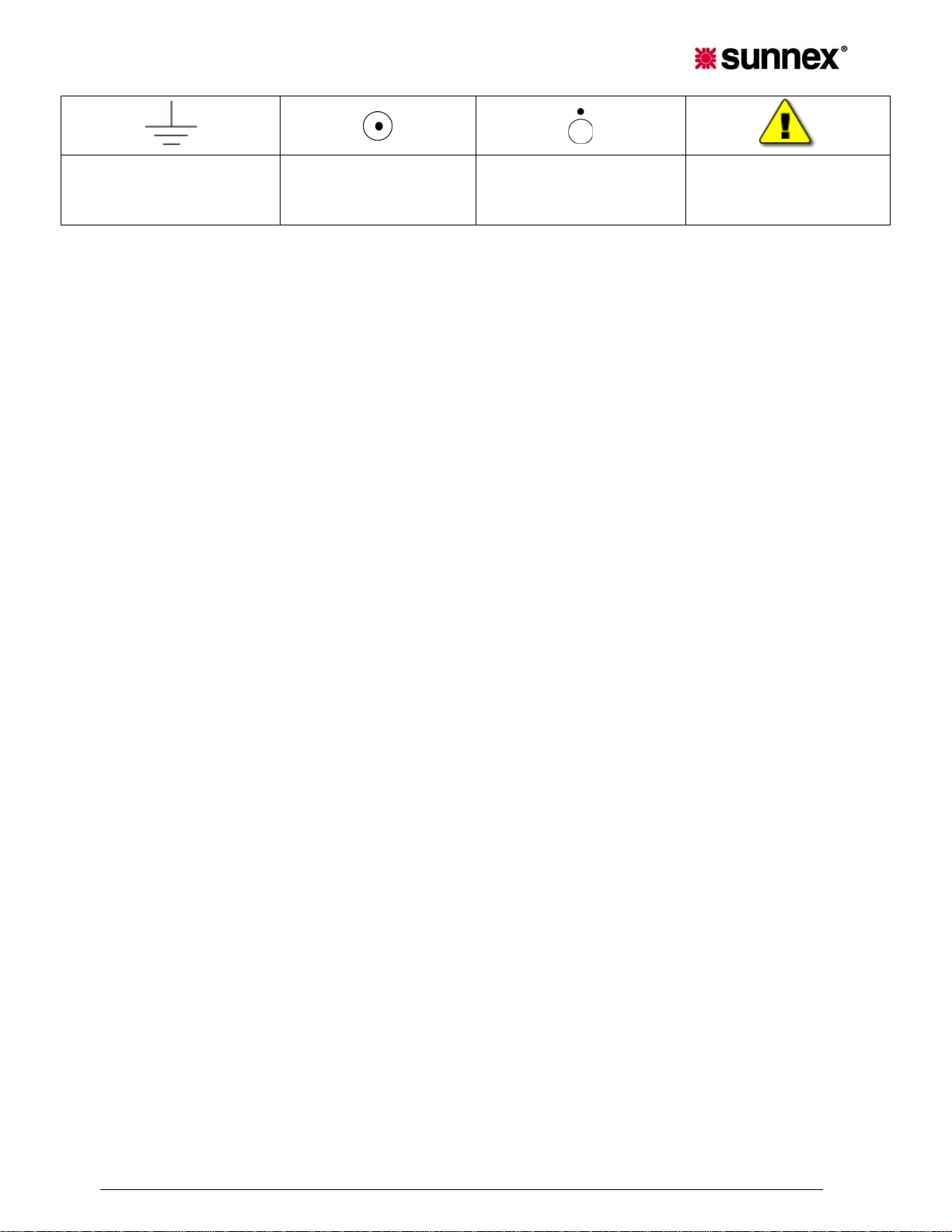
GROUND
SWITCH ON
SWITCH OFF
CAUTION
9. WARRANTY
Limited Warranty
Sunnex warrants that the Product, if properly used, will be free from defects in material and
workmanship, for a period of three (3) years from the date of shipment to Customer. This
Limited Warranty extends only to the original buyer. If the Product is determined to be
defective within the warranty period, Sunnex, at its option, will repair or replace the Product, at
no charge or refund the then-current value of the Product.
8.2 Disclaimers and Limitations.
This Limited Warranty shall be the sole remedy of Customer and the sole liability of
Sunnex to Customer.
This Limited Warranty does not extend or apply to any defects, failures or damage due to
or resulting from: (a) acts of God, accident, misuse, use of the Product other than its
normal and customary manner, abuse or negligence; (b) everyday wear and tear; (c)
alteration or modification of, or to any part of, the Product; (d) improper operation and
maintenance; or (d) any repairs or attempted repairs by anyone other than Sunnex. This
Limited Warranty does not cover any products sold AS IS or WITH ALL FAULTS. This
Limited Warranty excludes the replacement of bulbs for the Product.
TO THE FULL EXTENT PERMITTED BY APPLICABLE LAW, THIS LIMITED
WARRANTY REPLACES ALL OTHER WARRANTIES OR CONDITIONS, EXPRESS OR
IMPLIED INCLUDING, WITHOUT LIMITATION, ANY AND ALL IMPLIED WARRANTIES
OF MERCHANTABILITY AND FITNESS FOR A PARTICULAR PURPOSE. SUNNEX
DISCLAIMS ALL OTHER WARRANTIES AND CONDITIONS, EXPRESS OR IMPLIED,
INCLUDING, WITHOUT LIMITATION, IMPLIED WARRANTIES OF TITLE,
NONINFRINGEMENT, ABSENCE OF LIENS OR INCUMBRANCES,
MERCHANTABILITY AND FITNESS FOR A PARTICULAR PURPOSE, REGARDLESS
OF WHETHER SUNNEX KNOWS OR HAS REASON TO KNOW OF CUSTOMER’S
PARTICULAR NEEDS. IF IMPLIED WARRANTIES MAY NOT BE DISCLAIMED UNDER
APPLICABLE LAW, THEN ANY IMPLIED WARRANTIES THAT MAY BE IMPOSED BY
LAW ARE LIMITED IN DURATION TO THE LIMITED WARRANTY PERIOD SET FORTH
HEREIN, AND THEREAFTER ANY IMPLIED WARRANTIES ARE EXPRESSLY
DISCLAIMED.
No employee, agent, dealer, reseller or distributor of Sunnex is authorized to modify this
Limited Warranty, or to make any additional warranties.
Sunnex Tristar Service & Installation Manual
12
Page 13

REPAIR, REPLACEMENT OR REFUND, AS PROVIDED UNDER THIS LIMITED
WARRANTY, ARE CUSTOMER’S SOLE AND EXCLUSIVE REMEDIES. IN NO EVENT
SHALL SUNNEX BE LIABLE FOR ANY DIRECT, INDIRECT, SPECIAL, INCIDENTAL,
CONSEQUENTIAL OR TORT DAMAGES OR LOSSES, WHETHER TO PERSON OR
PROPERTY, INCLUDING DEATH, ARISING OUT OF OR RESULTING FROM ANY
BREACH OF WARRANTY OR ANY OTHER LEGAL THEORY, OR ARISING OUT OF OR
IN CONNECTION WITH THE PRODUCT OR CUSTOMER’S USE OF THE PRODUCT,
EVEN IF SUNNEX IS ADVISED OF THE POSSIBILITY OF SUCH DAMAGES. IN ANY
EVENT, THE TOTAL LIABILITY OF SUNNEX TO YOU FOR ANY CAUSE
WHATSOEVER SHALL BE LIMITED TO THE PURCHASE PRICE YOU PAID FOR THE
PRODUCT. THIS LIMITATION SHALL APPLY REGARDLESS OF THE FORM OF
ACTION, WHETHER IN CONTRACT OR TORT (INCLUDING, WITHOUT LIMITATION,
NEGLIGENCE).
SOME STATES DO NOT ALLOW THE EXCLUSION OR LIMITATION OF INCIDENTAL
OR CONSEQUENTIAL DAMAGES, OR ALLOW LIMITATIONS ON HOW LONG AN
IMPLIED WARRANTY LASTS, SO THE ABOVE LIMITATIONS OR EXCLUSIONS MAY
NOT APPLY TO YOU. THIS LIMITED WARRANTY GIVES YOU SPECIFIC LEGAL
RIGHTS, AND YOU MAY ALSO HAVE OTHER RIGHTS THAT VARY FROM STATE TO
STATE.
8.3 Claims Procedure.
(a) Customer must contact Sunnex at (800)-445-7869 with a request for warranty service or to
report a technical issue. Sunnex Technical Support will attempt to identify, diagnose and
resolve the reported problem via the telephone.
(b) If attempts by Sunnex to resolve a reported problem are unsuccessful, Customer will then
be provided with a Customer-specific Returned Merchandise Authorization number (“RMA”).
The RMA number must be noted on any correspondence to Sunnex and displayed
prominently on the outside packaging of any Product shipped to Sunnex.
(c) Within ten (10) days of receipt of the RMA number, Customer mu st ship the Product to
Sunnex at Customer’s expense (insuring the Product is recommended) in either its original
packaging or packaging affording an equal degree of protection, to Sunnex Inc. 3 Huron Drive,
Natick MA 01760, with a statement describing the problem in reasonable specificity. Proof of
purchase must be included to obtain warranty service. Sunnex will not be held responsible for
shipping damages that occur in transit. Any damage to the Product during shipping will not be
covered under this Limited Warranty and shall be subject to a service charge.
(d) Subject to the limitations specified herein, upon receipt, Sunnex will inspect the shipped
Product and, at its sole discretion, repair or replace the Product with the same or a like product
to the extent it does not conform to this Limited Warranty. In the event Sunnex, at its sole
discretion, opts to replace the Product, should said product be discontinued or no longer be
offered for sale by Sunnex, a like product in design and functionality will be provided to
Customer.
(e) Sunnex will ship the repaired Product or a replacement to Customer within ten (10)
business days after receipt from the date that Sunnex receives the Product. Standard
shipments to the Customer will be paid by Sunnex. Sunnex assumes no responsibility for
shipment delays by the carrier.
(f) If Customer requires warranty service to be provided in less than ten (10) business days,
but not less than three (3) business days, Sunnex will charge Customer an additional One
Hundred Dollars ($100.00) express handling charge per request for each Product.
8.4 Customer Responsibilities.
(a) To validated warranty customer is required to fill out online or provided warranty card.
Sunnex Tristar Service & Installation Manual
13
Page 14
(b) Customer is required to follow the user manual associated with the Product for proper
operation.
(c) Customer is required to perform periodic preventive maintenance as called for in the
user manual associated with the Product.
(d) Any modifications or repairs made to the Product without prior written authorization
from Sunnex will render this Limited Warranty null and void. Instances whereby this is
determined to be the case by Sunnex technical staff will be subject to an initial service
charge of $75.00 ($25.00 evaluation charge and $50.00 minimum labor cost).
8.5 Miscellaneous.
In the event that any provision of this Limited Warranty should be or becomes invalid
and/or unenforceable during the warranty period, the remaining provisions shall continue
in full force and effect.
The provisions of this Limited Warranty shall be governed by the laws of the
Commonwealth of Massachusetts without regard to its conflict of laws principles. This
Limited Warranty shall not be modified except by an agreement signed by both parties
specifically referencing this Limited Warranty.
This Limited Warranty represents the entire agreement between Sunnex and Customer
with respect to the subject matter herein and supersedes all prior or contemporaneous
oral or written communications, representations, understandings or agreements relating to
this subject.
For service assistance or resolution of a service problem, or for Product or warranty
information, write to Sunnex Inc. 3 Huron Drive, Natick MA 01760, or visit
www.sunnex.com
8.6 Optional Extended Limited Warranty Plan.
The purchase of the Optional Extended Limited Warranty extends the duration of this
Limited Warranty from a period of three (3) years to a period of five (5) years from the
date of shipment to Customer. The Optional Limited Warranty may be purchased at the
time of the original purchase of the Product or the Extended Limited Warranty to become
effective and apply to the Product. Customer must pay the appropriate Extended Limited
Warranty fee and upon initial purchase, register each Product with Sunnex within thirty
(30) days from the date of shipment to Customer by Sunnex, or a Sunnex authorized
dealer or reseller.
Sunnex Customer Service
Sunnex Inc, USA + 1 508 651 0009
Sunnex Equipment AB Sweden + 46 565 177 00
Warranty + 1 508 651 0009
.
10. TROUBLESHOOTING
Please refer to the following table for troubleshooting.
Sunnex Tristar Service & Installation Manual
14
Page 15
CAUTION! DISCONNECT THE LIGHT FROM THE POWER
SUPPLY BEFORE ATTEMPTING ANY OF THE
ELECTRICAL CHECKS MENTIONED BELOW.
PROBLEM POSSIBLE CAUSE SOLUTION
No light from light head Light head is on OFF
position
No light from light head, when
ON/OFF switch is ON
Bulb has not been
installed or it has burned
Turn on the ON/OFF switch to
ON position
Refer to bulb replacement
procedure in the manual
out
Fuse is blown Inspect / replace the fuse
following the fuse replacement
procedure
No power to the
transformer box
Transformer is
malfunctioning
Check for facility power to the
transformer box
Check for 14 V AC output at
the transformer when it is
under load.
Incorrect bulb installed Install correct bulb
Bulb burns out quickly Incorrect bulb installed in
Install correct bulb
the light head
Light output is irregular in its
shape or intensity
Incorrect bulb installed in
the light head
Install correct bulb
Bulb/reflector is not
seated in its holder
correctly
No light from light head even
when the bulb and fuse are in
good condition, light head
flashes intermittently when light
Circuit or wiring problem
within transformer, arm
assemblies or other part
of lighting system
head or arms are moved
Adjust the bulb/reflector so it
seats in the holder properly.
Check all wiring connections. If
problem cannot be repaired,
call Sunnex Customer Service
Sunnex Tristar Service & Installation Manual
15
Page 16

REV. 1.3
APRIL 2009
 Loading...