

Page 1
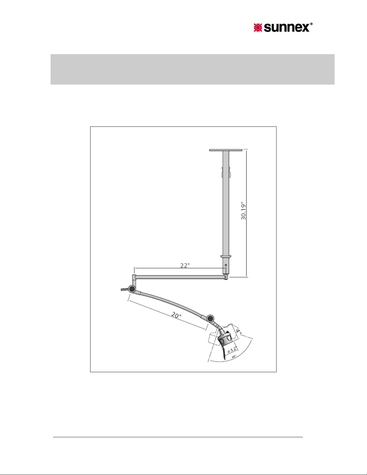
Installation Instructions
Sunnex HM Exam Light
Models: HM1006-37W, HM28002W, HM1000-37W, HM2017-44
1.1 Applications
This HM LIGHT is intended to be used as a medical examination lamp in consulting rooms and health
care centers.
HM Ceiling
Sunnex HM Light Service & Installation Manual
1
Page 2
1.2 Cleaning and Disinfection
The lamp fixture can be cleaned as needed with a damp cloth and a mild detergent. For disinfection use a
soft cloth with a disinfectant solution such as isopropyl alcohol. NOTE! Do not introduce any fluids to the
inside of the lamp head as this could cause a fire hazard.
The glass lens can be cleaned with a damp cloth and a mild detergent and i nside part of the lens can be
easily cleaned with Q-tips.
Technical Data
2.1 Manufacturer
Sales office
Sunnex, Inc.
3 Huron Drive
Natick, MA 01760, USA
Phone: 508-651-0009
Fax: 508-651-0099
Email: [email protected]
Production Facility
Sunnex, Inc.
3 Huron Drive
Natick, MA 01760, USA
Phone: 508-651-0009
Fax: 508-651-0099
Email: [email protected]
2.2 Technical Data
Main Voltage
Nominal effect
Safety Class
Transformer
120VAC 60Hz (230V 50Hz available)
60W
I
Medical Grade Plug-in transformer
INPUT: 120VAC, 60Hz, 0.5A, OUTPUT: +12VAC, 5.0A MAX.
Part# GS-1451
INPUT: 230VAC, 50Hz, OUTPUT: +11.5VAC
Part# 18395 (EURO), 18396 (UK), 18397 (AUSTRALIA)
Bulb
12V/20W/NSP
Color Temperature (CCT) 3584 Kelvin (at 1meter)
Color rendition index (CRI) 95 (at 1meter)
Total irradiance 16 W/m2 (at 1meter)
Certifications ETL Listed: CAN/CSA-C22.2 No. 601.1-M90
EN60601-1, UL60601-1, EN60601-2-41
IEC60601-2-41, IEC 60601-1-2 (2001-09) 2nd edition
(EN55011:1991, Group I Class B)
Only original accessories must be used with HM light. The HM light is equipped with a push-button
ON-OFF switch on the lamp head that should be used to turn the light ON and OFF.
EMC
The lamp complies with the EMC requirements in accordance with EN 60601-1-2. Wireless
transmission equipment e.g. mobile phones etc. should not be used in the vicinity of the lamp since
this can affect the function. Special care should be observed during the use of strong sources of
interference e.g. diathermy and the like, so that the diathermy cables not are placed on or close to the
lamp. If in doubt consult your technician or the supplier. Accessories other than here mentioned are
not allowed to use as they may negatively affect emissions and immunity. The complete light must be
recycled in accordance with WEEE standard.
Sunnex HM Light Service & Installation Manual
2
Page 3
2.3 Transportation and Storage
This light is packaged in card board and should be transported protected from moisture. The light
should be stored in a dry environment and room temperature.
Transportation and storage temperature: -5°F / -20°C to 140°F / 60°C
Humidity < 95%
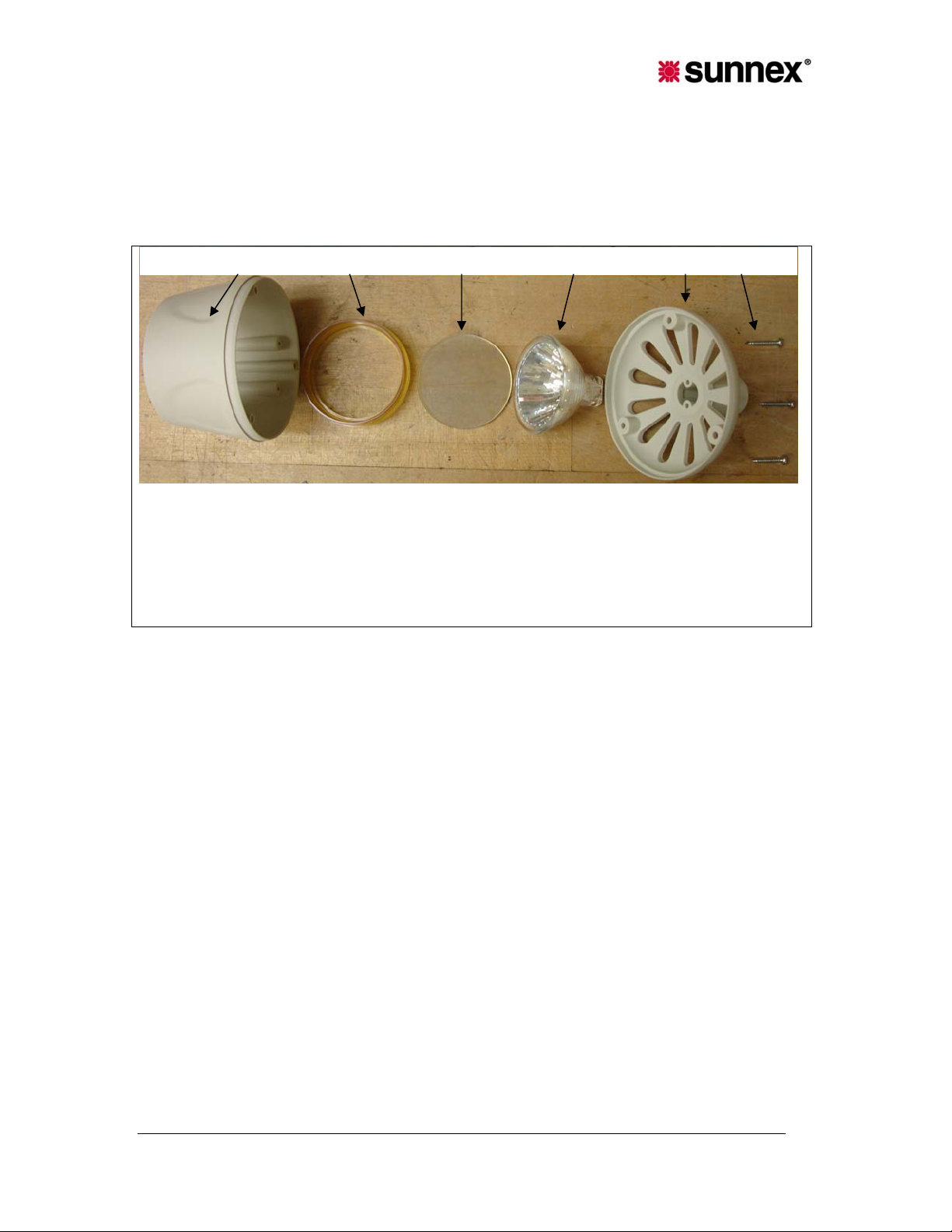
2.4 Bulb replacement
1. Lamp front, part#: 18018
2. Bulb support, part#: 18291
3. Color filter, part#: 18676
4. MR 16 bulb, part#: 18562
5. Lamp back, part# 18016
6. Screws, part#: 4475057
1. Unplug lamp from power source and wait at least one hour for lamp to cool.
2. Loosen the connecting cable from the transformer to make sure that lamp is not supplied with
voltage.
3. Unscrew the three screws from back cover of the lamp.
4. Remove the halogen cold light bulb from its socket.
5. Replace the damaged halogen cold light reflector. Only Sunnex cold light reflector with part. no.
18562 must be used. NOTE! Make sure the cold light reflector is clean and without fingerprints.
6. Refit the back cover, with the three screws. NOTE! The color filter must not be removed, since the
color temperature of the lamp depends on this. A damaged color filter must be replaced immediately.
CAUTION! Be sure the lampshade components are properly seated when screws are tightened!
2.0 Assembly Instructions
Sunnex HM Light Service & Installation Manual
3
Page 4
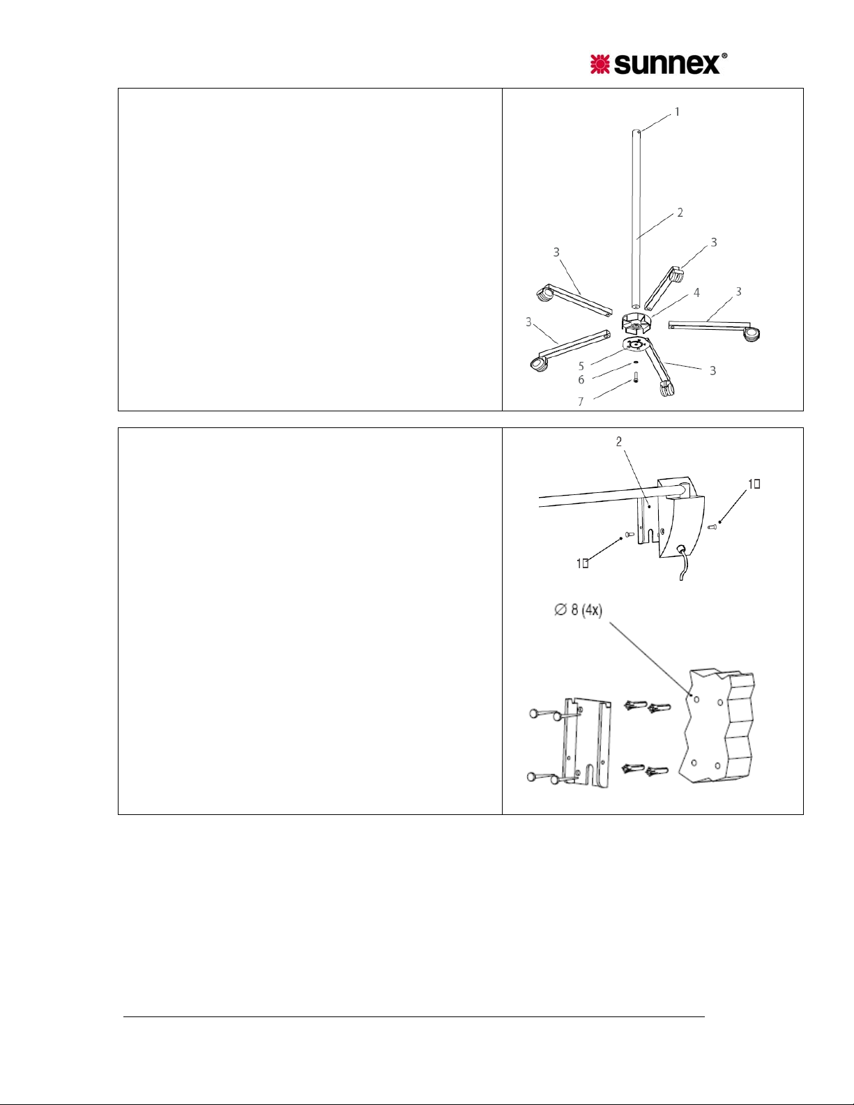
2.1 HM LIGHT Mobile (HM1006-37W)
1. Place the pole (2) in the center housing (4)
2. Press down until you feel resistance.
Assemble the clamp plate (5) using the provided screw (7)
and washer (6). Do not tighten the screw. The teeth on the
plate should face inwards.
3. Insert each of the 5 legs into the center housing, and
place the 2 lockable casters on opposite sides.
4. Tighten the screw (7). Secure the legs in the housing by
lining up the teeth on the clamp plate (5) with the holes in
the legs.
2.2 HM LIGHT Wall – Articulating Arm (HM28002W)
Wall Mount - 20W - Plug-in transformer
A. Remove the screws in the wall plate (1&2).
B. Remove the wall plate from casing (2)
C. Drill 4 holes (8mm) in alignment with the holes in wall
plate. Make sure plate is leveled. NOTE! Wall plate must
be mounted to wall stud or structural member.
D. Insert the anchors into the holes and attach the wall
plate with the screws provided.
E. Attach wall casing to the wall plate with provided screws.
F. Make sure that the wall casing is securely fastened to
the plate and adjust and tighten the arm as needed.
G. Plug the transformer into power outlet and turn on lamp
with switch on back of lamp head.
CAUTION! The arm is equipped with friction joints. Do not tighten the joints excessively as
this will cause uneven movement and could damage the arm.
d
Sunnex HM Light Service & Installation Manual
4
Page 5
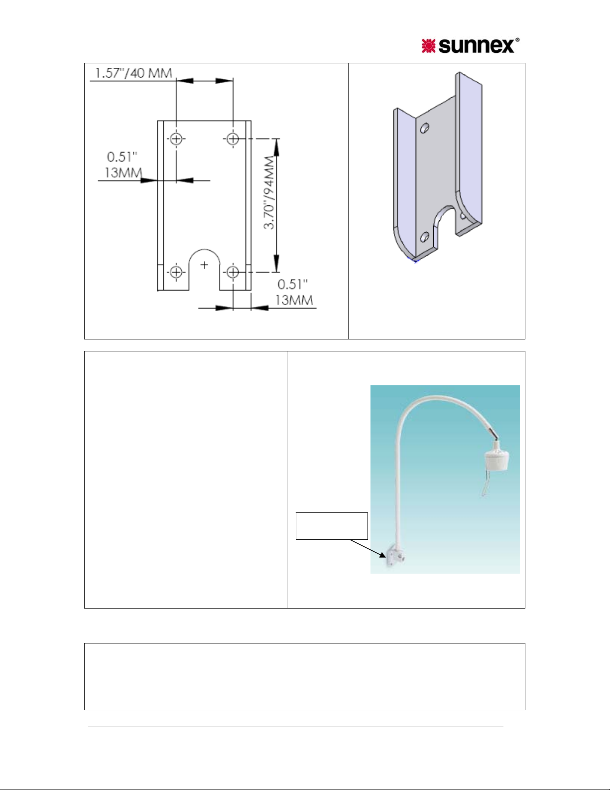
HM WALL BRACKET HOLE PATTERN
2.3 HM LIGHT Wall - Gooseneck Arm
(HM1000-37W)
1. Mount the light using four screws. There
are four holes on the universal mount.
2. Be sure transformer plug is not plugged
into power source at this time.
3. After universal mount is secured, plug in
the plug-in transformer to use the light.
Universal
Joint
HM Light Wall – Gooseneck Arm
2.4 HM LIGHT Ceiling (HM2017-44)
1. Securely fasten lamp down tube from ceiling. It is recommended that 6-5/16" diameter or larger
fasteners of the proper length for your individual application be used. Be sure down tube is securely
mounted to structural framework. Down tube should be mounted plumb and square to ceiling surface.
Sunnex HM Light Service & Installation Manual
5
Page 6
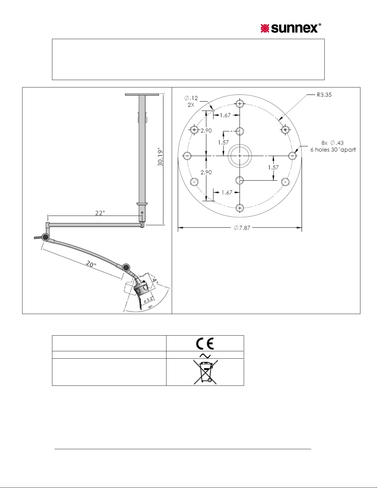
2. Be sure transformer plug is not plugged into power source at this time.
3. After down tube support is secured plug electrical connectors at the end of the down tube support
and lamp arm together.
HM CEILING DOWN TUBE HOLE PATTERN
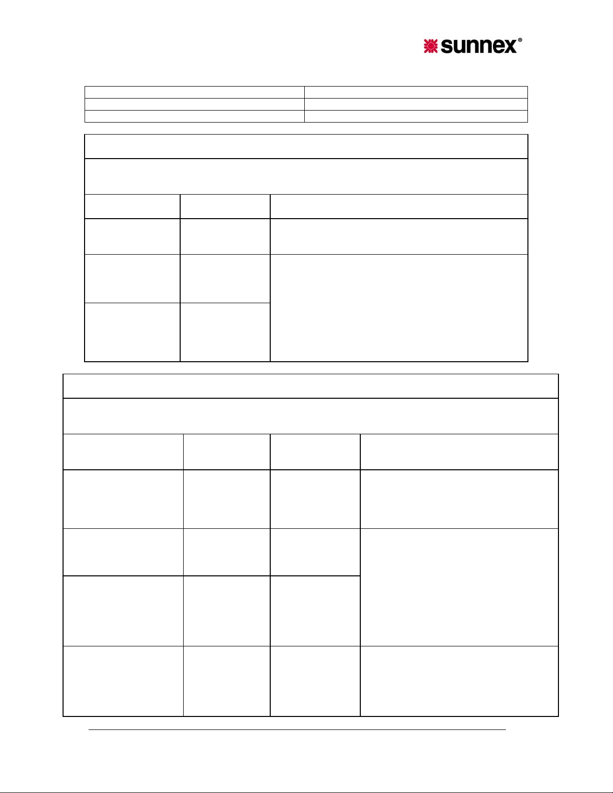
2.6 Symbols
CE-Mark
AC powered:
This product must be sorted as Waste
from Electrical and Electronic
Equipment (WEEE):
3. Sunnex Limited Warranty
3.1 Limited Warranty.
Sunnex warrants that the Product, if properly used, will be free from def ects in materi al and
workmanship, for a period of three (3) years from the date of shipment to Customer. This Limited
Warranty extends only to the original buyer. If the Product is determined to be defective within the
Sunnex HM Light Service & Installation Manual
6
Page 7

warranty period, Sunnex, at its option, will repair or replace the Product, at no charge or refund the
then-current value of the Product.
3.2 Disclaimers and Limitations.
This Limited Warranty shall be the sole remedy of Customer and the sole liability of Sunnex to
Customer.
This Limited Warranty does not extend or apply to any defects, failures or damage due to or
resulting from: (a) acts of God, accident, misuse, use of the Product other than its normal and
customary manner, abuse or negligence; (b) everyday wear and tear; (c) alteratio n or
modification of, or to any part of, the Product; (d) improper operation and maintenance; or (d) any
repairs or attempted repairs by anyone other than Sunnex. This Limited Warranty does not cover
any products sold AS IS or WITH ALL FAULTS. This Limited Warranty excludes the replacement
of bulbs for the Product.
TO THE FULL EXTENT PERMITTED BY APPLICABLE LAW, THIS LIMITED WARRANTY
REPLACES ALL OTHER WARRANTIES OR CONDITIONS, EXPRESS OR IMPLIED
INCLUDING, WITHOUT LIMITATION, ANY AND ALL IMPLIED WARRANTIES OF
MERCHANTABILITY AND FITNESS FOR A PARTICULAR PURPOSE. SUNNEX DISCLAIMS
ALL OTHER WARRANTIES AND CONDITIONS, EXPRESS OR IMPLIED, INCLUDING,
WITHOUT LIMITATION, IMPLIED WARRANTIES OF TITLE, NONINFRINGEMENT, ABSENCE
OF LIENS OR INCUMBRANCES, MERCHANTABILITY AND FITNESS FOR A PARTICULAR
PURPOSE, REGARDLESS OF WHETHER SUNNEX KNOWS OR HAS REASON TO KNOW OF
CUSTOMER’S PARTICULAR NEEDS. IF IMPLIED WARRANTIES MAY NOT BE DISCLAIMED
UNDER APPLICABLE LAW, THEN ANY IMPLIED WARRANTIES THAT MAY BE IMPOSED BY
LAW ARE LIMITED IN DURATION TO THE LIMITED WARRANTY PERIOD SET FORTH
HEREIN, AND THEREAFTER ANY IMPLIED WARRANTIES ARE EXPRESSLY DISCLAIMED.
No employee, agent, dealer, reseller or distributor of Sunnex is authorized to modify this Limited
Warranty, or to make any additional warranties.
REPAIR, REPLACEMENT OR REFUND, AS PROVIDED UNDER THIS LIMITED WARRANTY,
ARE CUSTOMER’S SOLE AND EXCLUSIVE REMEDIES. IN NO EVENT SHALL SUNNEX BE
LIABLE FOR ANY DIRECT, INDIRECT, SPECIAL, INCIDENTAL, CONSEQUENTIAL OR TORT
DAMAGES OR LOSSES, WHETHER TO PERSON OR PROPERTY, INCLUDING DEATH,
ARISING OUT OF OR RESULTING FROM ANY BREACH OF WARRANTY OR ANY OTHER
LEGAL THEORY, OR ARISING OUT OF OR IN CONNECTION WITH THE PRODUCT OR
CUSTOMER’S USE OF THE PRODUCT, EVEN IF SUNNEX IS ADVISED OF THE
POSSIBILITY OF SUCH DAMAGES. IN ANY EVENT, THE TOTAL LIABILITY OF SUNNEX TO
YOU FOR ANY CAUSE WHATSOEVER SHALL BE LIMITED TO THE PURCHASE PRICE YOU
PAID FOR THE PRODUCT. THIS LIMITATION SHALL APPLY REGARDLESS OF THE FORM
OF ACTION, WHETHER IN CONTRACT OR TORT (INCLUDING, WITHOUT LIMITATION,
NEGLIGENCE).
SOME STATES DO NOT ALLOW THE EXCLUSION OR LIMITATION OF INCIDENTAL OR
CONSEQUENTIAL DAMAGES, OR ALLOW LIMITATIONS ON HOW LONG AN IMPLIED
WARRANTY LASTS, SO THE ABOVE LIMITATIONS OR EXCLUSIONS MAY NOT APPLY TO
YOU. THIS LIMITED WARRANTY GIVES YOU SPECIFIC LEGAL RIGHTS, AND YOU MAY
ALSO HAVE OTHER RIGHTS THAT VARY FROM STATE TO STATE.
3.3 Claims Procedure.
(a) Customer must contact Sunnex at (800)-445-7869 with a request for warranty service or to report a
technical issue. Sunnex Technical Support will attempt to identify, di agnose and re solve the rep orted
problem via the telephone.
(b) If attempts by Sunnex to resolve a reported problem are unsuccessful, Customer will then be
provided with a Customer-specific Returned Merchandise Authorization number (“RMA”). The RMA
number must be noted on any correspond ence to Sunnex and displayed promine ntly on the outsi de
Sunnex HM Light Service & Installation Manual
7
Page 8

packaging of any Product shipped to Sunnex.
(c) Within ten (10) days of receipt of the RMA number, Customer must ship th e P ro duc t t o S unn e x a t
Customer’s expense (insuring the Product is recommended) in either its original packaging or
packaging affording an equal degree of protection, to Sunnex Inc. 3 Huron Drive, Natick MA 01760,
with a statement describing the problem in reasonable specificity. Proof of pur cha se m ust b e
included to obtain warranty service. Sunnex will not be held responsible for shipping damages that
occur in transit. Any damage to the Product during shipping will not be covered under this Limited
Warranty and shall be subject to a service ch arge.
(d) Subject to the limitations specified herein, upon receipt, Sunnex will inspect the shipped Product
and, at its sole discretion, repair or replace the Product with the same or a like produ ct to the extent it
does not conform to this Limited Warranty. In the even t Sunnex, at its sole discreti on, opts to re place
the Product, should said product be discontinued or no lo nger be offered for sale by Sunnex, a like
product in design and functionality will be provided to Customer.
(e) Sunnex will ship the rep aired Product or a replacement to Custom er within ten (10) business d ays
after receipt from the date that Sunnex receives the Product. Standard shipments to the Customer will
be paid by Sunnex. Sunnex assumes no responsibility for shi pment delays by the carrier.
(f) If Customer requires warranty service to be provided in less than ten (10) business days, but not
less than three (3) business days, Sunnex will charge Customer an additional One Hundred Dollars
($100.00) express handling charge per request fo r each Produ ct.
3.4 Customer Responsibilities.
(a) To validated warranty customer is required to fill out online or provided warranty card.
(b) Customer is required to follow the user manual associated with the Product for proper
operation.
(c) Customer is required to perform periodic preventive maintenance as called for in the user
manual associated with the Product.
(d) Any modifications or repairs made to the Product without prior written authorization from
Sunnex will render this Limited Warranty null and void. Instances whereby this is determined to
be the case by Sunnex technical staff will be subject to an initial service charge of $75.00 ($25.00
evaluation charge and $50.00 minimum labor cost).
3.5 Miscellaneous.
In the event that any provision of this Limited Warranty should be or becomes invalid and/or
unenforceable during the warranty period, the remaining provisions shall continue in full force and
effect.
The provisions of this Limited Warranty shall be governed by the laws of the Commonwealth of
Massachusetts without regard to its conflict of laws principles. This Limited Warranty shall not be
modified except by an agreement signed by both parties specifically referencing this Limited
Warranty.
This Limited Warranty represents the entire agreement between Sunnex and Customer with
respect to the subject matter herein and supersedes all prior or contemporaneous oral or written
communications, representations, understandings or agreements relating to this subje ct.
For service assistance or resolut ion of a service problem, or for Product or warranty information,
write to Sunnex Inc. 3 Huron Drive, Natick MA 01760, or visit www.sunnex.com
3.6 Optional Extended Limited Warranty Plan.
The purchase of the Optional Extended Limited Warranty extends the duration of this Limited
Warranty from a period of three (3) years to a period of five (5) years from the date of shipment to
Customer. The Optional Limited Warranty may be purchased at the time of the original purchase
of the Product or the Extended Limited Warranty to become effective and apply to the Product.
Customer must pay the appropriate Extended Limited Warranty fee and upon initial purchase,
register each Product with Sunnex within thirty (30) days from the date of shipment to Customer
by Sunnex, or a Sunnex authorized dealer or reseller.
.
Sunnex HM Light Service & Installation Manual
8
Page 9
Sunnex Customer Service
Sunnex Inc, USA + 1 508 651 0009
Sunnex Equipment AB Sweden + 46 565 177 00
Warranty + 1 508 651 0009
Guidance and manufacturer’s declaration — electromagnetic emissions
The HM LIGHT is intended for use in the electromagnetic environment specified below. The
customer or the user of the HM LIGHT should assure that it is used in such an environment.
Emissions test Compliance Electromagnetic environment — guidance
Emissions test
CISPR 15
Complies
HM LIGHT may not be interconnected with other
electrical equipment.
Harmonic
emissions
IEC 61000-3-2
Voltage
fluctuations/ flicker
emissions
Not applicable
.
Not applicable
The HM LIGHT is suitable for use in all establishments,
including domestic establishments and those directly
connected to the public low-voltage power supply
network that supplies buildings used for domestic
purposes.
IEC 61000-3-3
Guidance and manufacturer’s declaration — electromagnetic immunity
The HM LIGHT Image Intensifier is intended for use In the electromagnetic environment specified bel ow. The
customer or the user of the HM LIGHT Image Intensifier should assure that it is used in such an environment.
Immunity test
Electrostatic discharge
(ESD)
lEC 61000-4.2
lEC 60601
test level
±6 kV contact
±8 kV air
Compliance
level
±6 kV contact
±8 kV air
Electromagnetic environment —
guidance
Floors should be wood, concrete or
ceramic tile, If floors are covered with
synthetic material, the relative humidity
should be at least 30 %.
Electrical fast
transient/burst
lEC 61000-4-4
Surge
lEC 61000-4-5
Voltage dips, short
Interruptions and
voltage variations on
power supply Input lines
IEC 61000-4-11
±2 kV for power
supply lines
±2 kV for power
supply lines
Mains power quality should be that of a
typical commercial or hospital
±1 kV differential
mode
±2 kV common
mode
<5 % UT (>95 %
dip In U
) for 0,5
T
cycle
40 % U
T
(60 % dip in U
±1 kV differential
mode
±2 kV common
mode
<5 % U
dip In UT) for 0.5
cycle
40 % U
(60 % dip in U
)
T
(>95 %
T
T
environment.
Mains power quality should be that of a
typical commercial or hospital
environment, If the user of the HM LIGHT
Image Intensifier requires continued
operation during power mains
)
Interruptions, It is recommended that the
T
Sunnex HM Light Service & Installation Manual
9
Page 10
Power frequency (50/60
Hz) magnetic field
IEC 6 1000-4-8
for 5 cycles
70 % U
T
(30 % dip In U
for 25 cycles
<5% U
T
(>95 % dip In
U
) for 5 s
T
for 5 cycles
70 % U
(30 % dip in U
)
T
for 25 cycles
<5% U
(>95 % dip in U
for 5 s
3 A/m 0,3 A/m
T
T
HM LIGHT Image Intensifier be powered
from an uninterruptible power supply or a
battery.
)
T
)
T
If Image distortion occurs, It may be
necessary to position the HM LIGHT
Image Intensifier further from sources of
power frequency magnetic fields or to
install magnetic shielding. The power
frequency magnetic field should be
measured In the intended installation
location to assure that It is sufficiently low.
NOTE UT is the a.c. mains voltage prior to application of the test level.
Guidance and manufacturer’s declaration — electromagnetic immunity
The HM LIGHT is intended for use In the electromagnetic environment specified below. The customer or the
user of the HM LIGHT should assure that it is used in such an environment.
Immunity test
lEC 60601 test
level
Compliance
level
Electromagnetic environment — guidance
Sunnex HM Light Service & Installation Manual
10
Page 11
Conducted RF
IEC 61000-4-6
Radiated RF
lEC 61000-4-3
3 V
rms
150 kHz to 80 MHz
3 V/m
80 MHz to 2,5 GHz
3 V
3 V/m
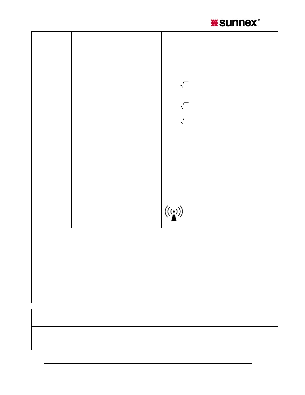
Portable and mobile RF communications
equipment should be used no closer to any part of
the HM LIGHT, including cables, than the
recommended applicable to the frequency of the
transmitter.
Recommended separation distance
d = 1,2
P
d = 1,2
d = 2,3
P 80 MHz to 800 MHz
P
800 MHz to 2,5 0Hz
where P is the maximum output power rating of
the transmitter in watts (W) according to the
transmitter manufacturer and d is the
recommended separation distance In metres (m).
Field strengths from fixed RF transmitters, as
determined by an electromagnetic site survey,
should be less than the compliance level in each
frequency range.
b
a
Interference may occur in the vicinity of equipment
marked with the following symbol:
NOTE 1 At 80 MHz and 800 MHz, the higher frequency range applies.
NOTE 2 These guidelines may not apply in all situations. Electromagnetic propagation is affected by
absorption and reflection from structures, objects and people.
a
Field strengths from fixed transmitters, such as base stations for radio (cellular/cordless) telephones and land
mobile radios, amateur radio, AM and FM radio broadcast and TV broadcast cannot be predicted theoretically with
accuracy. To assess the electromagnetic environment due to fixed RF transmitters, an electromagnetic site survey
should be considered. If the measured field strength in the location in which the HM LIGHT is used exceeds the
applicable RF compliance level above, the HM LIGHT should be observed to verify normal operation. if abnormal
performance is observed, additional measures may be necessary, such as re-orienting or relocating the HM
LIGHT.
b
Over the frequency range 150 kHz to 80 MHz, field strengths should be less than 3 V/m.
Recommended separation distances between
portable and mobile RF communications equipment and the HM LIGHT
The HM LIGHT is intended for use in an electromagnetic environment in which radiated RF disturbances are
controlled. The customer or the user of the HM LIGHT can help prevent electromagnetic interference by
maintaining a minimum distance between portable and mobile RF communications equipm ent (transmitters)
and the HM LIGHT as recommended below, according to the maximum output power of the communications
Sunnex HM Light Service & Installation Manual
11
Page 12
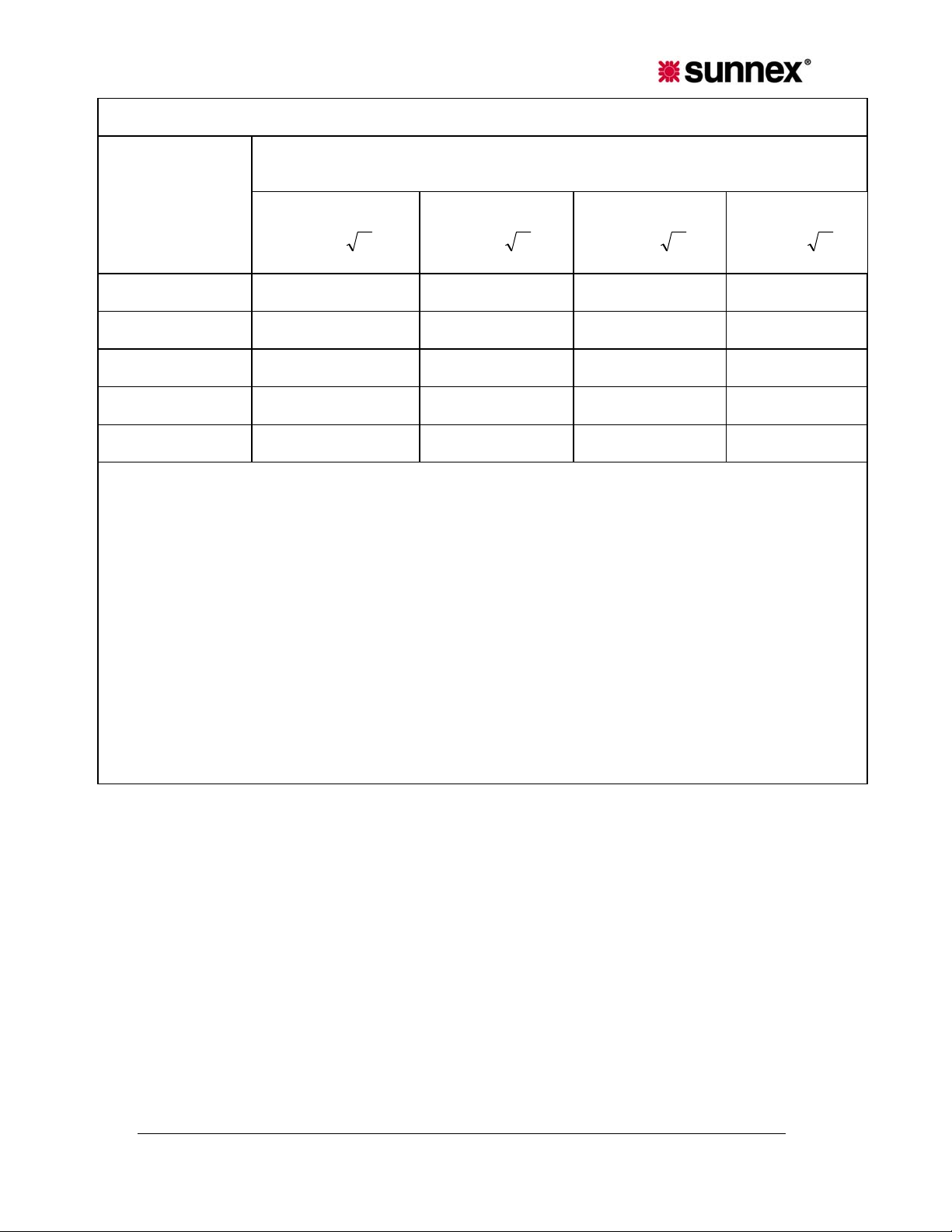
equipment.
Separation distance according to frequency of transmitter
Rated maximum
output power of
transmitter
w
0,01 0,35 1,2 0,35 0,35
0,1 1,1 3,8 1,1 1,1
1 3,5 12 3,5 3,5
10 11 38 11 11
100 35 120 35 35
For transmitters rated at a maximum output power not listed above, the recommended separation distance d
in metres (m) can be determined using the equation applicable to the frequency of the transmitter, where P is
the maximum output power rating of the transmitter in watts (W) according to the transmitter manufacturer.
150 kHz to 80 MHz
outside ISM bands
d = 3,5
P
150 kHz to 80 MHz
in ISM bands
d = 12 P
m
80 MHz to 800
MHz
d = 1,2 P
800 MHz to 2,5
GHz
d = 2,3 P
NOTE 1 At 80 MHz and 800 MHz, the separation distance for the higher frequency range applies.
NOTE 2 The ISM (industrial, scientific and medical) bands between 150 kHz and 80 MHz are 6,765 MHz to
6,795 MHz; 13,553 MHz to 13,567 MHz; 26,957 MHz to 27,283 MHz; and 40,66 MHz to 40,70 MHz.
NOTE 3 An additional factor of 10/3 is used In calculating the recommended separation distance for
transmitters In the ISM frequency bands between 150 kHz and 80 MHz and In the frequency range 80 MHz
to 2,5 GHz to decrease the likelihood that mobile/portable communications equipment could cause
interference If it is inadvertently brought into patient areas.
NOTE 4 These guidelines may not apply in all situations. Electromagnetic propagation is affected by
absorption and reflection from structures, objects and people.
REV. 1
JULY 2008
Sunnex HM Light Service & Installation Manual
12
 Loading...