

Page 1
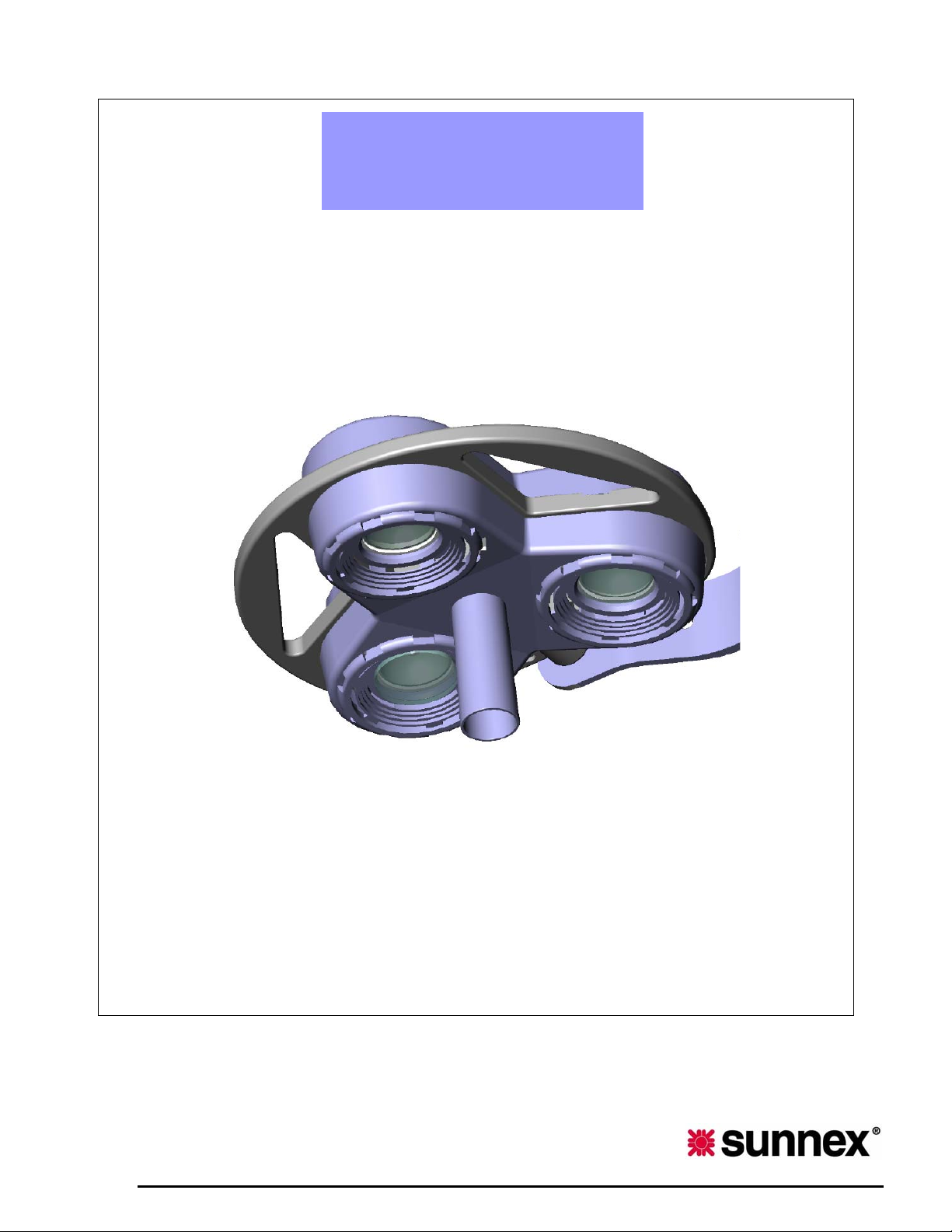
SUNNEX MEDICALIGHT
©
INSTALLATION & OPERATING MANUAL
Celestial Star
CS2050M (Mobile) CS2050W (Wall)
CS2050C (Ceiling) CS2050D (Dual)
WWW.SUNNEXMEDICAL.COM
INSTALLATION AND OPERATING MANUAL
Page 2

Dear Customer:
We appreciate that you have chosen to purchase a Sunnex Medical product and believ e that it will fulf ill your
expectations. Sunnex takes great pride in our products which have been designed and manufactured in
accordance with our strict ISO 9001 certified quality system, UL and CE electrical standards and, if
applicable, the United States Food and Drug Administration’s regulations. You will find Sunnex brand
products to be reliable, durable, and an exceptional value providing innovation while maintaining a low
overall lifetime cost.
We try our outmost to focus on our customers needs. Our sales and customer service staff will assist
you with any questions you might have regarding your new Sunnex product - the functionality, installation or
other concerns. Sunnex’s network of business partners - Nation al and Regional distributors may also be called
upon to provide excellent advice and additional sales support.
Again, I thank you for purchasing Sunnex products and I believe it will serve you well.
Anders Utter
President, Sunnex, Inc.
• SAVE THIS PRODUCT MANUAL
• READ ALL INSTRUCTIONS BEFORE ASSEMBLY AND USE
• IF YOU DON’T UNDERSTAND ANY GUIDELINES IN THIS MANUAL, CALL
DISTRIBUTOR OR MANUFACTURER
• DO NOT USE THIS LIGHT IF IT IS DAMAGED, BROKEN, OR HAS MISSING
PARTS
1
INSTALLATION AND OPERATING MANUAL
Page 3

CONTENTS
1. Introduction ………………………………………..………………..
1.1 Contents and Packaging
1.2 About the Light
2. Technical Description ……………………………..…………………
2.1 Technical Data
2.2 Symbols
2.3 Main Components and Dimensions
3. Customer Responsibilities ……………………………………………
4. Pre-wiring Instructions………………………………………………
4.1 Standard Receptacle Installations
4.2 Hard-wire to Junction Box
5. Installation Instructions ………………………………………………
Ceiling Light……………………………………………………………
5.1 Pre-installation Instructions
5.2 Installation Instructions
Ceiling Dual Light ……………………………………………………..
5.3 Pre-installation Instructions
5.4 Installation Instructions
Wall Light ……………………………………………………………..
5.5 Installation Instructions
Mobile Light …………………………………………………………..
5.6 Installation Instructions
6. Operating Instructions…………………………………………………
7. Maintenance ……………………………………………………………
7.1 Cleaning and Disinfection
7.2 Handle Autoclaving
7.3 Bulb Replacement
7.4 Fuse Replacement
8. Warranty ……………………………………………………………...
9. Troubleshooting ………………………………………………………
10. Appendix ……………………………………………………………..
INSTALLATION AND OPERATING MANUAL
3
5
7
8
8
8
15
16
18
19
20
23
26
27
2
Page 4
1. Introduction
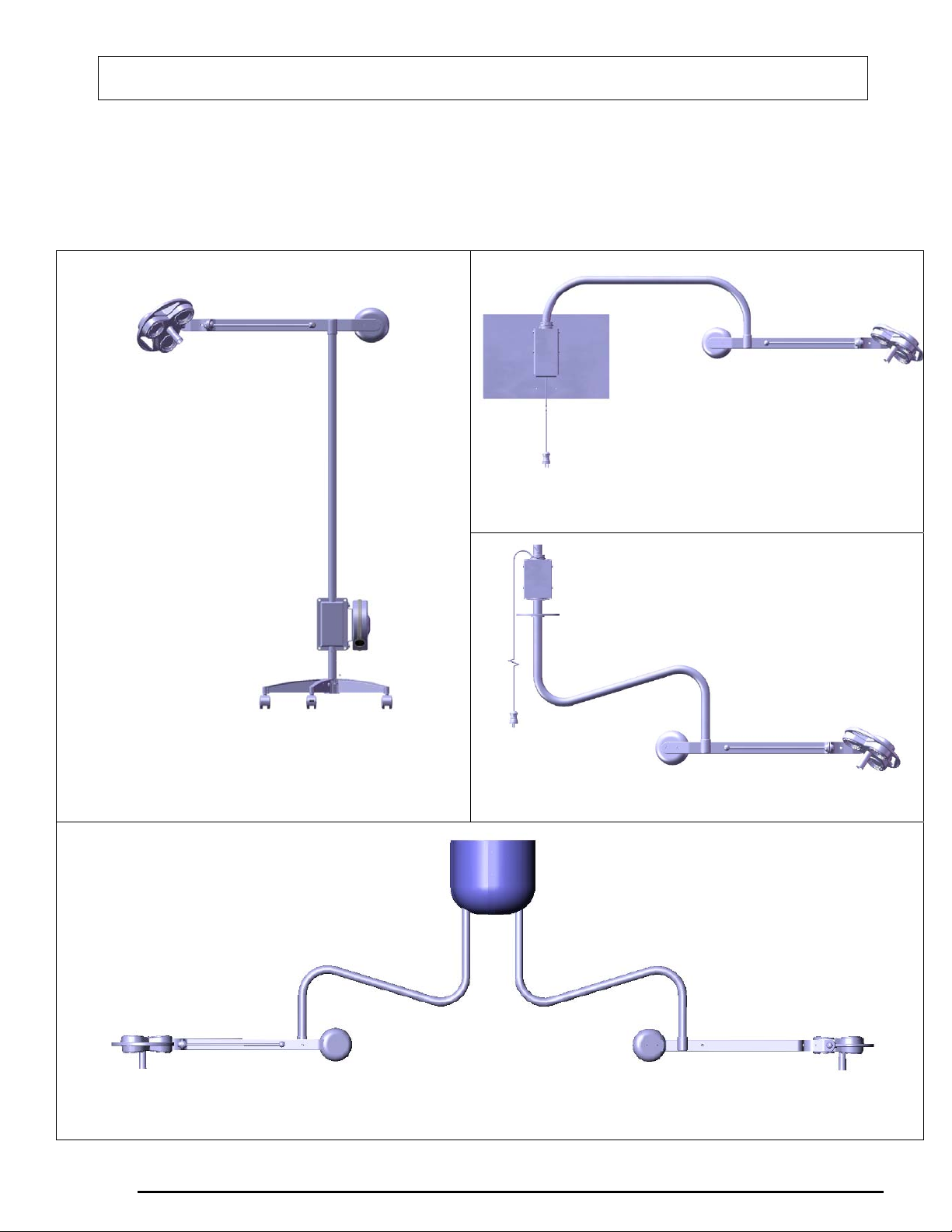
1.1 Contents and Packaging
Wall
Mobile
Ceiling
Ceiling Dual
3
INSTALLATION AND OPERATING MANUAL
Page 5
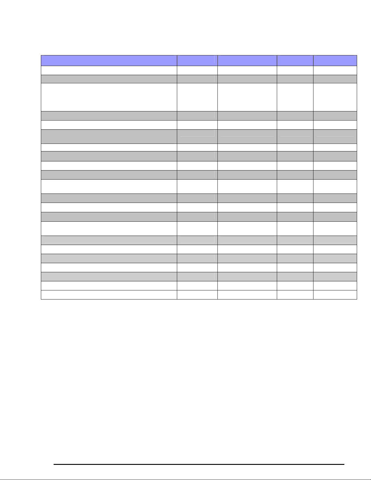
Packaging Checklist
CONTENTS CEILING DUAL CEILING WALL MOBILE
BALANCE ARM ASSEMBLY 1 2 1 1
CEILING ARM & TRANSFORMER ASSEMBLY 1 2
BOX CONTAINING
- ONE (1) SET OF DOME COVERS (LEFT
& RIGHT)
- ONE (1) SEISMIC BRACKET DUAL
U ARM & TRANSFORMER ASSEMBLY 0 0 1 0
WALL BOARD 0 0 1 0
VERTICAL POLE ARM & TRANSFORMER
ASSEMBLY
CASTER BASE WITH WHEELS 0 0 0 1
COUNTER BALANCE 1 2 1 1
ACCESSORY BAG TO INCLUDE FOLLOWING:
- STERILIZABLE HANDLE 1 2 1 1
- INSTRUCTION MANUAL &
WARRANTY CARD
- FLAT HEAD SCREWS (1/4-20 X 1/2”) 2 4 2 2
- PAN HEAD SCREWS (8-32 X 1/2”) 3 6 3 3
- ALLEN WRENCH – 5/32 1 2 1 1
- PAN HEAD PLASTIC SCREWS (1/4-20 X
1/2”)
- HEX BOLT (1/4-20 X 3/4”) 0 0 4 0
- ALLEN WRENCH – 5/16 0 1 0 0
- HEX BOLTS (3/8-24 X 3/4”) 0 4 0 0
- HEX NUTS (3/8-24 X 1/2”) 0 4 0 0
- ALLEN WRENCH – 1/8 1 1 1 1
- CEILING COVER (AESTHETIC) 1 2 0 0
DUAL SEISMIC MOUNTING BRACKET 0 1 0 0
0
0 0 0 1
1 2 1 1
4 8 4 0
1
0
0
MOUNTING BRACKET IS NOT INCLUDED FOR CEILING SINGLE LIGHT
ONE MOUNTING BRACKET IS INCLUDED FOR CEILING DUAL LIGHT
*Carefully check the contents of the shipment. Report shortages and/or errors, to Sunnex or your
dealer's customer service department, within five (5) working days. The carton and its inserts
should be kept for inspection by the transportation company if you see damage in the packages
received.
1.2 About the Light
You will find your Celestial Star light, with its many features, ideal for a myriad of clinical
applications, minor surgical procedures and gross examination. It provides excellent illumination
with a minimum of shadows for use in emergency departments, trauma rooms, and other critical
care areas.
Surgical Light Features
• High Light Output … up to 60,000 Lux
• High Color Temperature, 3300 Degree Kelvin
4
INSTALLATION AND OPERATING MANUAL
Page 6
• Patented Lamp Shade reduces heat output
• Unparalleled Flexibility with Extensive Reach and Range of Motion
• Drift Free Balance Arm Design
• Quick & Easy Bulb Replacement
• Removable Sterilizable Handle
This manual will assist you in assembling your light, introduce some of its most important and
prominent features, and provide suggestions for its care. The light is intended for use in medical
specialty environments where illumination is required for various medical examinations and
procedures. The light must be operated with the safety of the user and patient in mind. Please read
this manual carefully and any other instructions prior installing the equipment.
2. Technical Description
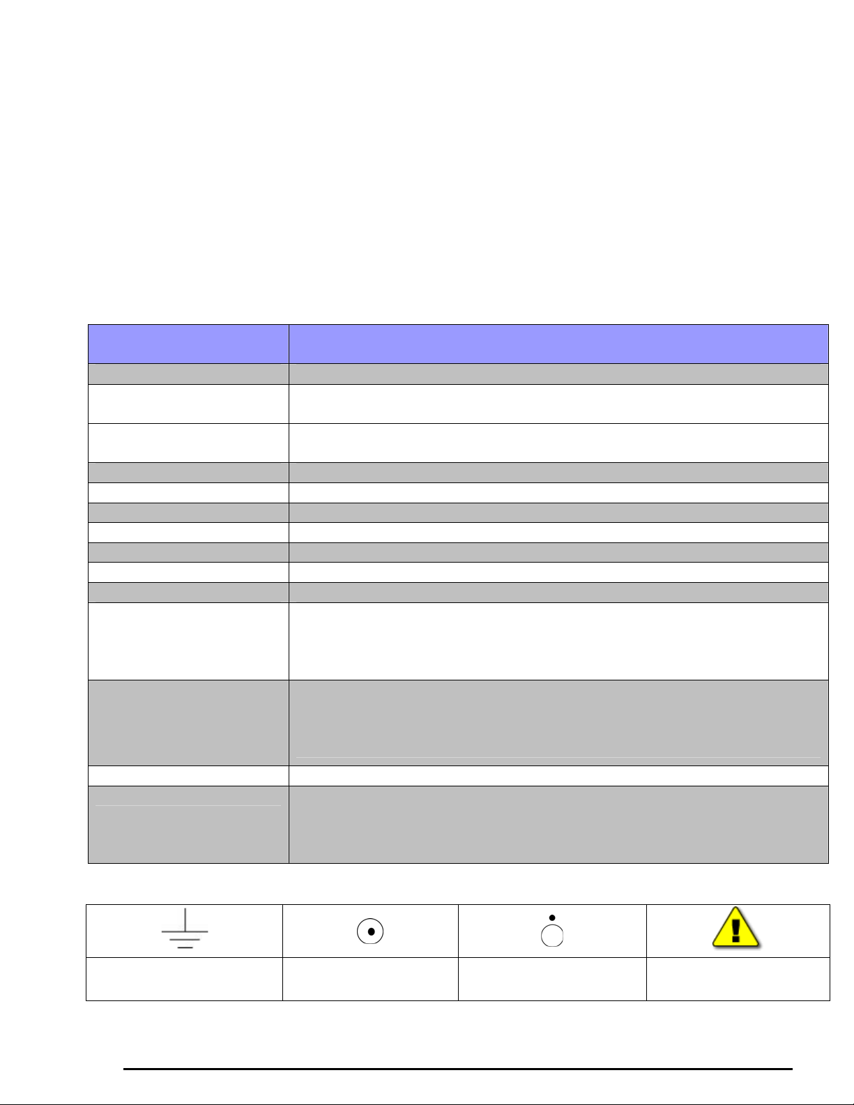
2.1 Technical Data
WARNING! Do not use this device in the presence of flammable anesthetics (EXPLOSION RISK)
SPECIFICATION
VALUE & CONDITION
Power supply 120V - 60Hz and 230V - 50Hz-60Hz (+/-10%)
Fuse 120V :Sunnex part# 18565 (2 AMP, 250V, 1/4” X 1-1/4”, SLOW BLOW)
230V: Sunnex part# 18641 (1.25 AMP, 250V, 5mm X 20mm, SLOW BLOW)
Nominal Effect 120Vac, 60Hz, 3 X 35W - 1.5A
230Vac, 50Hz, 3 X 35W - 1.0A
Light Source Halogen bulb - Dichroic 3 X 12V/35W/10°
Bulb Life 4,000 hours
Light Intensity 38,000 Lux at 1 Meter
Color Temperature 3,300 Degree Kelvin
Color Rendering Index 96
Total Irradiance 116W/m2
Medical Standard Class II
Total Weight Ceiling – 56 lbs (25 Kg)
Ceiling Dual - 130 lbs (59 Kg) (including dual seismic bracket)
Wall - 64 lbs (29 Kg) (including wall board)
Mobile - 40 lbs (18 Kg)
Moment (One 29” [74cm] long ceiling arm) = 50 lbs X 57 inches = 2,850 lbs-inches
(322 Nm)
(One 39” [100cm] long ceiling arm) = 50 lbs X 67 inches = 3,350 lbs-inches
(379 Nm)
Mode of Operation Continuous
Certifications ETL Listed: CAN/CSA-C22.2 No. 601.1-M90
EN60601-1, UL60601-1, EN60601-2-41
UL60601-2-41, IEC 60601-1-2 (2001-09) 2nd edition (EN55011:1991, Group
I Class B)
2.2 Symbols
GROUND
SWITCH ON
SWITCH OFF
INSTALLATION AND OPERATING MANUAL
CAUTION
5
Page 7
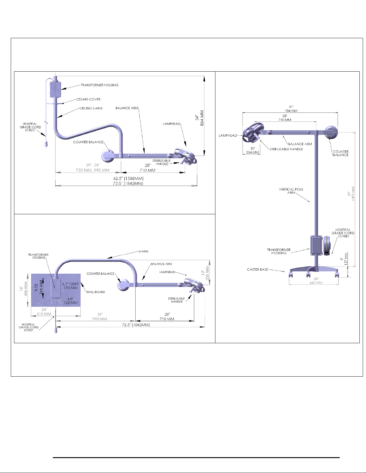
2.3 Main Components and Dimensions
Figure 1. Ceiling
Figure 3. Mobile (120V Model)
(230V Model does not come with cord reel,
Figure 2. Wall
instead it has cord hooks)
6
INSTALLATION AND OPERATING MANUAL
Page 8
3. Customer Responsibilities
Sunnex lights are built to provide exceptional
illumination and should impart you with years of
reliable service. Please follow the list below of
installation criteria to ensure proper steps are taken
prior to the mounting of the fixture, and help ensure
its appropriate use.
9 Note down product’s serial #
- Serial # is: _________
9 Carefully follow guidelines specified in this
manual (refer to figures 8, 9 and 10)
9 The contractor / installer has responsibility for
the superstructure / mounting brackets strength
and stability
9 Check with State and Local compliance boards
or engineering agencies to assure that all
installation and use codes are followed
INSTALLATION AND OPERATING MANUAL
7
Page 9
4. Pre-wiring Instructions
4.1 Standard Receptacle Installations
Standard models are designed to be used with standard hospital grade 3 prong grounded outlet
(receptacle) boxes. No modification or pre-wire is required.
4.2 Hard-wire to Junction Box
The hard-wiring instructions apply to following models only:
1. CS2050C-HW (Ceiling, 120V)
2. CS2050W-HW (Wall, 120V)
3. CS2050CE-HW (Ceiling, 230V)
4. CS2050WE-HW (Wall, 230V)
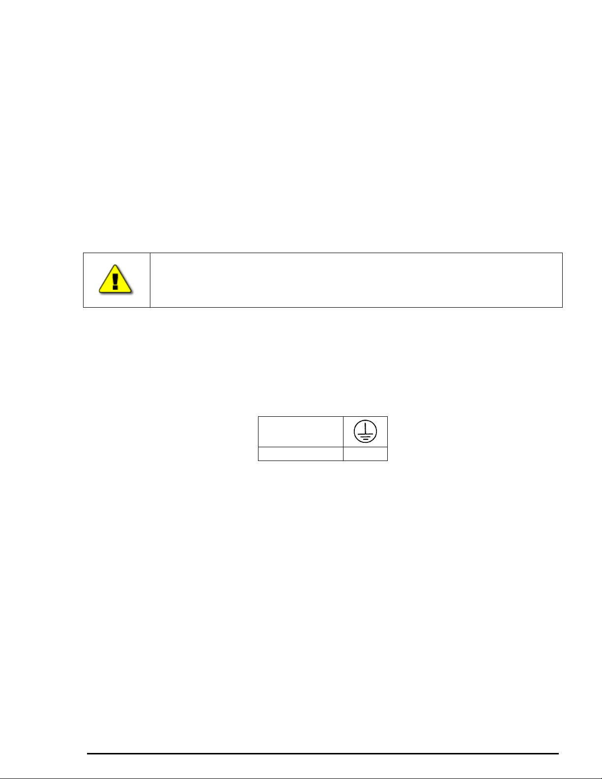
CAUTION: A LICENSED ELECTRICIAN MUST BE UTILIZED TO
PERFORM HARD-WIRING INSTALLATIONS, NATIONAL ELECTRICAL
CODE (NEC) MUST BE FOLLOWED DURING HARD-WIRING
INSTALLATION.
The lights mentioned above may be hard-wired with mains supply. During such hard-wiring, the
following instructions must be used:
1. The light is supplied with a hard service cord (STOW 18/3, 600V, -35O C to 105O C, 10
Amp per conductor @ 25O C, approved as water resistant, oil resistant, outdoor use)
suitable for ceiling hard-wiring applications. The cord has 3 conductors (Hot, Neutral and
Ground). The earth and neutral conductors are labeled as follows:
EARTH
NEUTRAL N
2. This STOW cord runs through a hole in the transformer box. The outer diameter of the
STOW cord is 0.378” (9.66mm). The hole in transformer box is 0.80” (20mm) for a metal
conduit of (trade size ½ or metric designator 16). The conduit must be fixed to the
transformer box with use of nut.
3. Connect the earth conductor with earthing of the facility, neutral conductor with neutral of
mains supply and hot conductor with hot terminal of mains supply.
4. Use proper wire nuts of appropriate electrical rating considering the STOW cord
specifications and electrical rating of the light.
5. Installation Instructions
Ceiling Light
5.1 Pre-installation Instructions
Please follow the directions for assembly carefully, as failure to do so may result in the voiding of
the lights warranty. * Note - any modification to the physical or mechanical structure of the lamp
will most likely be cause to void any UL, CE or other electrical listing which this product may
carry.
INSTALLATION AND OPERATING MANUAL
8
Page 10
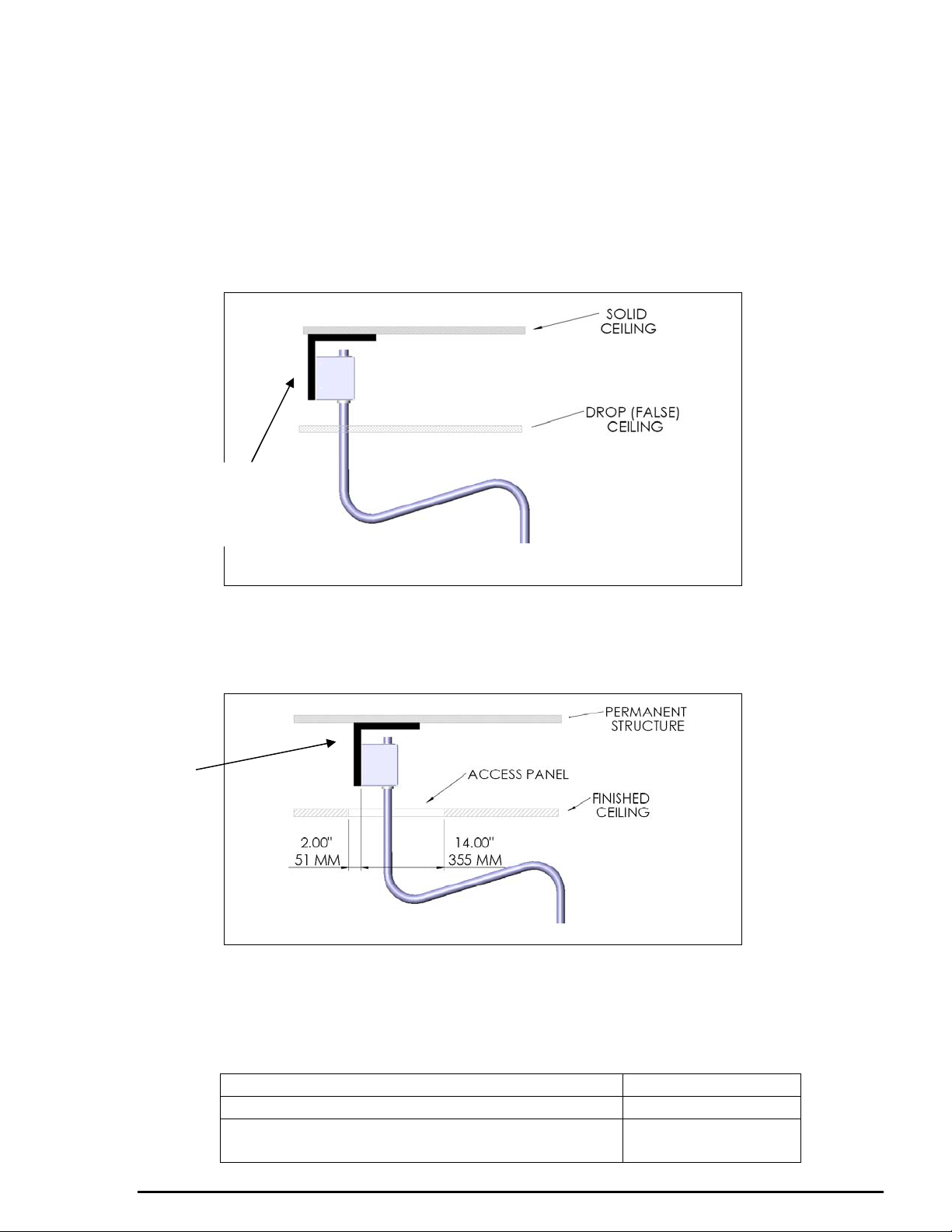
Refer to Figures 8, 9 & 10 and Table 1 for mounting heights and appendix A for hole pattern of the
transformer housing and optional brackets & plates.
1. NEVER attempt to affix a ceiling light directly to a drop (false) ceiling, as many are
not designed to withstand the weight requirements of the lighting systems, and may
result in damage to the ceiling, the lighting unit or both. Additionally this may
present a situation where failure may present a hazard to persons, resulting in
injury.
2. The transformer housing should be mounted against a permanent member just
above the drop (false) ceiling.
L-BRACKET
NOT
INCLUDED
L-BRACKET
NOT
INCLUDED
Figure 4
3. If during construction or remodeling, the ceiling surface is to be finished, it is
recommended that the installation of the light be accomplished first, leaving a small
access panel to facilitate access to the transformer housing and the safety fuses
mounted inside the mounting bracket.
Figure 5
4. Installations in which there is a distance of over 24 inches between the hard ceiling
surface and the drop (false) ceiling surface, often requires construction of an
additional support structure.
5. Weight:
One ceiling light (29” horizontal arm) 56 Lbs (25 Kg)
One ceiling light (39” horizontal arm) 58 Lbs (26 Kg)
Dual ceiling lights (29” horizontal arm)
130 Lbs (59 Kg)
plus dual seismic bracket
INSTALLATION AND OPERATING MANUAL
9
Page 11
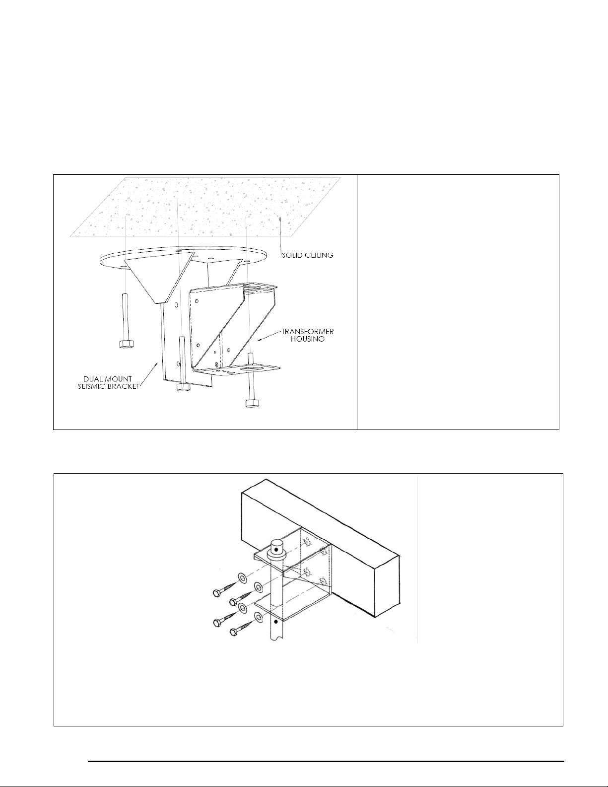
6. The contractor assumes the ultimate responsibility for the stability and strength of
the final mounted fixture.
MOUNTING TO A HORIZONTAL SURFACE
An L-bracket can be used to secure the transformer housing to vertical plane above the drop (false)
ceiling. Please refer to the dimensions of the optional bracket in appendix A.
Seismic steel bracket can be used to
secure the transformer housing to solid
ceiling surface or cement ceiling
surface. Minimum ½” (1.2 CM)
diameter bolts are recommended, with
minimum 2” (5.0 CM) depth into the
cement surface.
(This dual mount seismic bracket
comes with DUAL lights only)
NOTE
IT MAY BE NECESSARY TO
MOUNT THE DUAL BRACKET
BELOW THE HARD CEILING AT
A CERTAIN DISTANCE TO
ACHIEVE PROPER FLOOR TO
LIGHT DISTANCE. REFER TO
Figure 6
TABLE 1 AND FIGURE 8.
MOUNTING TO VERTICAL SURFACE
Figure 7
1. Prepare your solid surface (joist) with the mounting holes, per the hole locations of the housing
as shown in appendix B.
2. Secure transformer housing to the solid surface (joist), using four (4) 3/8” (M10) bolts, washers
& nuts, as required.
INSTALLATION AND OPERATING MANUAL
10
Page 12
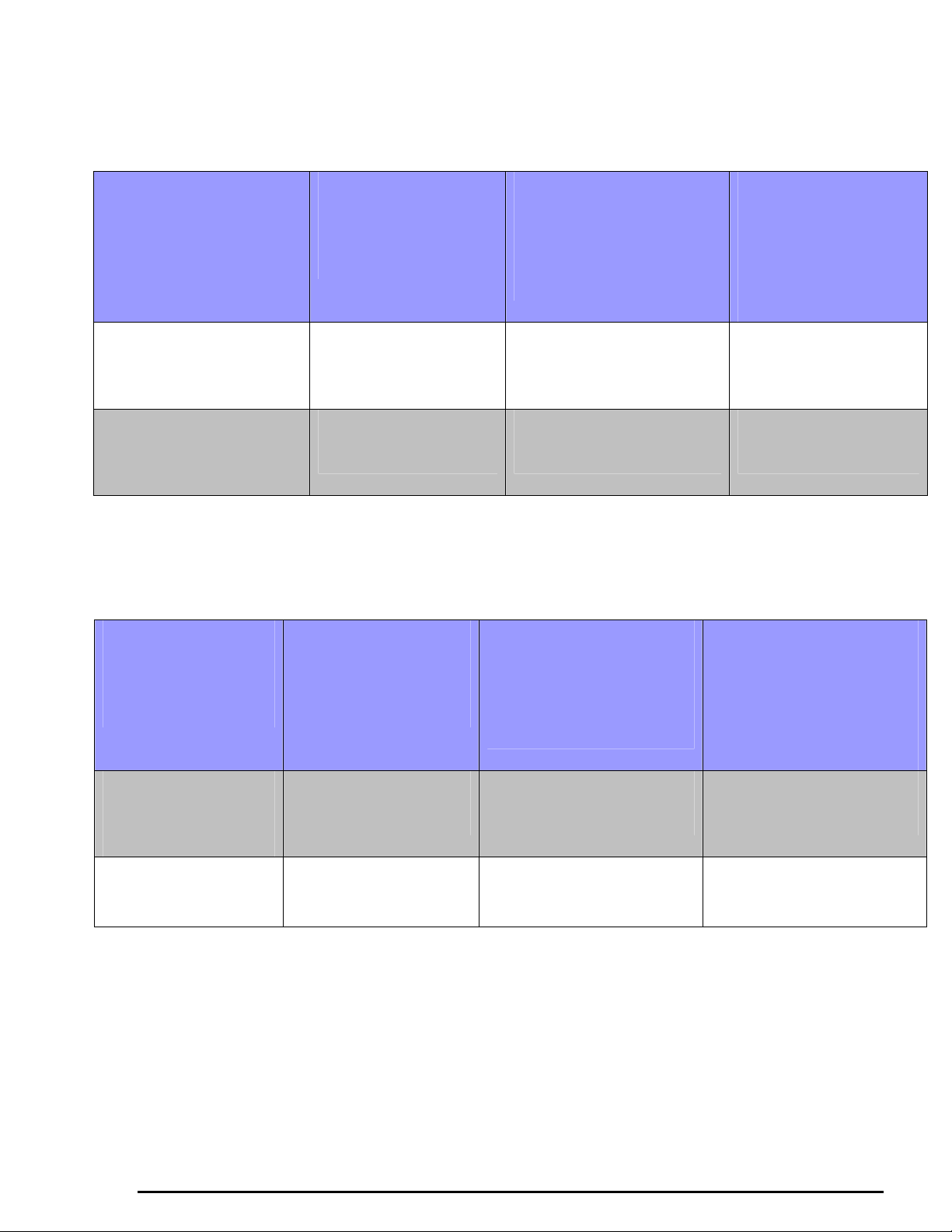
Table 1 Guideline for ceiling style mount
(Refers to Figures 8, 9 & 10)
CEILING LIGHT MOUNTING INSTRUCTIONS
WITH STANDARD EXTENSION Z-ARM
TO ACHIEVE FLOOR
IF DROP CEILING
TO LIGHT DISTANCE
OF
“A”
75 INCHES
(1905 mm
)
86 INCHES
(2184 mm)
______________________________________________________________________________
IS
“B”
8.0 FEET
(2440 mm)
9.0 FEET
(2740 mm)
MOUNT BOTTOM OF
TRANSFORMER
BRACKET
FROM FLOOR AT
“C”
99.8 INCHES
(2535 mm)
109.8 INCHES
(2789 mm)
GAP BETWEEN
DROP CEILING
AND CEILING ARM
MINIMUM 2”
REQUIRED
CEILING LIGHT MOUNTING INSTRUCTIONS
“D”
6.5”
(165mm)
4.5”
(114mm)
TO ACHIEVE
FLOOR TO LIGHT
DISTANCE OF
“A”
72 INCHES
(1828 mm)
85 INCHES
(2032 mm)
WITH EXTRA-HIGH EXTENSION Z-ARM
IF DROP CEILING
IS
“B”
10 FEET
(2280 mm)
11 FEET
(3350 mm)
MOUNT BOTTOM OF
TRANSFORMER
FROM FLOOR AT
123.8 INCHES
133.8 INCHES
GAP BETWEEN DROP
BRACKET
“C”
(3145 mm)
(3399 mm)
CEILING AND
CEILING ARM
“D”
MINIMUM 2”
REQUIRED
2.5”
(63mm)
4.5”
(114mm)
11
INSTALLATION AND OPERATING MANUAL
Page 13
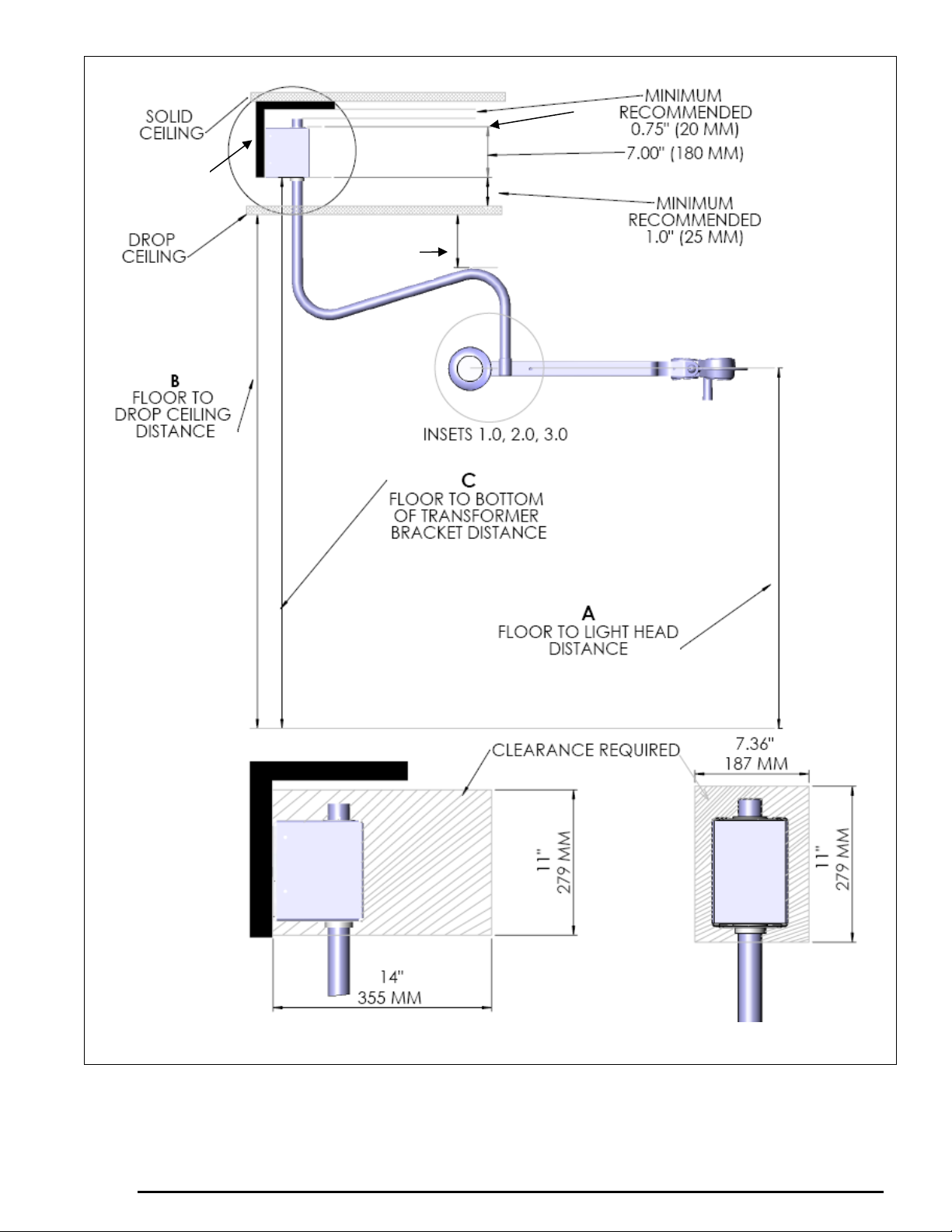
L-BRACKET
NOT
INCLUDED
2.25””
D
GAP
Figure 8. General mounting (shown with an L-bracket)
12
INSTALLATION AND OPERATING MANUAL
Page 14
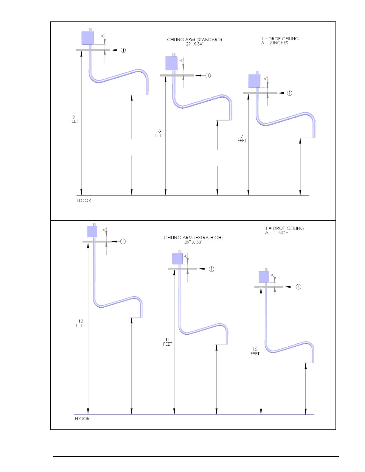
7 FEET
1 INCH
6 FEET
1 INCH
Figure 9. Ceiling light (Standard arm)
5 FEET
1 INCH
8 FEET
4 INCHES
7 FEET
4 INCHES
6 FEET
4 INCHES
Figure 10. Ceiling light (Extra-high arm)
INSTALLATION AND OPERATING MANUAL
13
Page 15
5.2 Installation Instructions
1. Slide transformer housing covers off of transformer brackets and set aside for future
installation.
2. Follow Table 1 and Figures 8, 9 & 10 to determine the location of installation.
3. Fasten the transformer housing to the desired location using four (4) 3/8” or M10 bolts (not
provided). The type of bolt will be dependent on your installation. These bolts may need
to be either lag or machine bolts. Minimum lag bolt length is 2-1/4” or 60mm. Verify that
the transformer housing is level. If not, arm will drift.
4. Position and install transformer housing cover on mounting bracket. Secure with plastic
screws (4) provided.
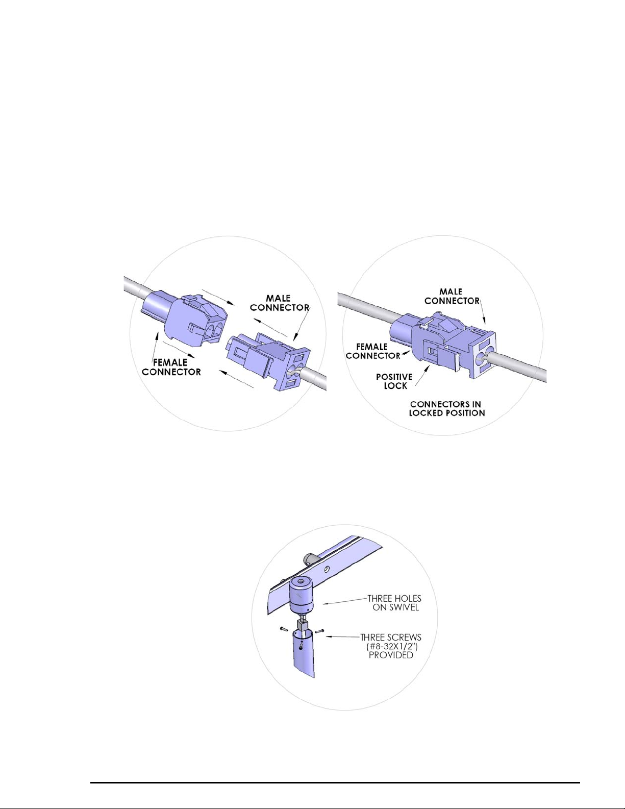
5. Connect the male connector with the female connector on swivel joint of the balance arm.
Connectors can be installed only one way. Ensure that connectors make a “CLICK” sound
for a positive lock.
Inset 1.0 (Figure 8)
6. Line up the holes on arm with the holes on the swivel joint on the balance arm. Use the (3)
pan head screws (#8-32X1/2”) provided to secure the connection.
Inset 2.0 (Figure 8)
7. Fix the round counter weight to other end of the lamp head balance arm. There are two
14
INSTALLATION AND OPERATING MANUAL
Page 16
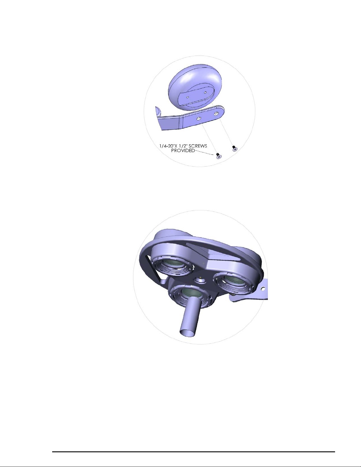
counter sunk holes on this end of the balance arm. Position the counter weight on the
opposite side of the counter sunk holes on the balance arm. Set the (2) flat head screws
(1/4-20” X 1/2”) supplied hex screws in the counter sunk holes and tighten them down
using provided (5/32”) Allen wrench.
Inset 3.0 (Figure 8)
8. Insert the sterilizable handle onto the mounting screw in the center of the lamp head and
rotate clockwise to tighten.
9. Plug the hospital grade plug into the outlet. The light is ready for use.
5.3 Pre-Installation Instructions (Ceiling Dual Light)
1. The dual mounted light comprises of two identical single ceiling mounted lights combined
with the use of a dual seismic ceiling bracket.
2. In order to utilize the provided aesthetic dome covers, the dual mount seismic bracket must
be used. These installations are predominantly below the false ceiling. If installing the dual
light above a drop ceiling, it is likely the bracket cover (dome) will not be required as the
bracket will not be visible to the user. Alternatively, the flat, plastic ceiling covers (provided
INSTALLATION AND OPERATING MANUAL
15
Page 17
with each light) can then be used to cover the hole in the drop ceiling created for the
extension arms.
3. The dimensions and recommended installation heights are identical to the single ceiling arm.
5.4 Installation Instructions (Ceiling Dual Light)
1. Follow instructions in sections 5.1 and 5.2 to complete installation of lights to ceiling.
Figure 11
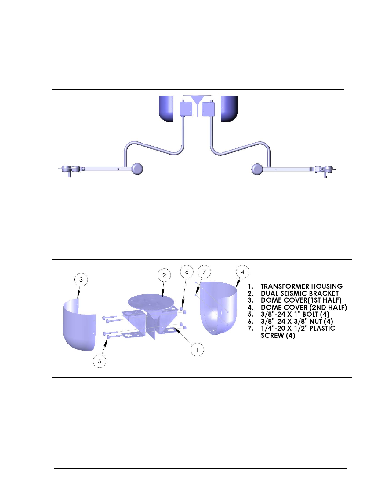
2. If using dual mount seismic bracket, securely fasten dual mount seismic bracket to a
structural member in the ceiling. Three ½" (12mm) holes on a 12" (30.4cm) bolt circle have
been provided on the flat plate of seismic bracket.
3. To install dome covers, position both halves of the dome and secure with the 4 plastic screws
provided. (There is a nylon collar on ceiling arm just below the transformer box, adjust the
collar by loosening the set screw on collar so it holds the dome covers).
Figure 12
5.5 Installation Instructions (Wall Light)
1. Locate the two wall studs or other permanent members to which the board is to be affixed.
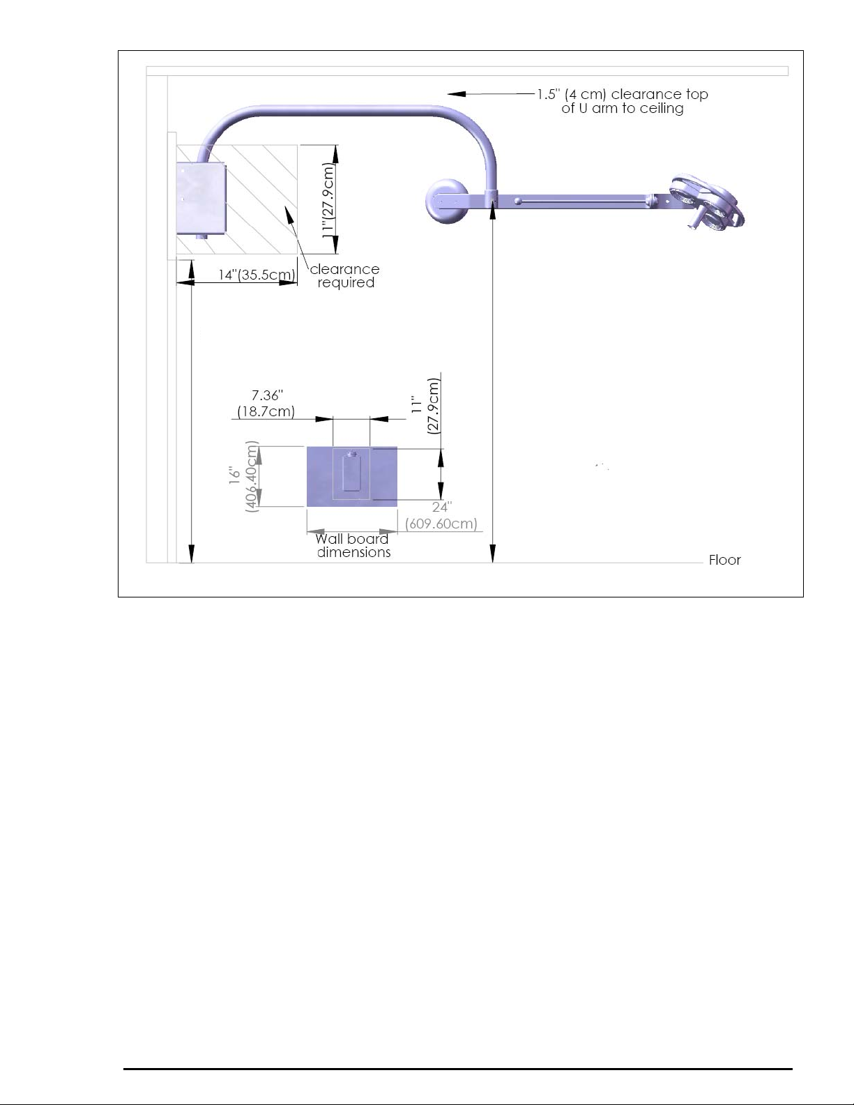
2. For a room with a floor-to-ceiling distance of eight feet, mark the position of the wall board on
the wall so the bottom of the wall bracket is 64.875” (165cm) from the floor surface. This will
result in floor to light clearance of 75” and should place the Extension U-arm where it will
move freely without scraping the ceiling. (This is based on the assumption that the floor-toceiling height is 8’ (2.4m)).
16
INSTALLATION AND OPERATING MANUAL
Page 18
64.875” (165cm)
floor to bottom of
wall board
75” (190cm)
Figure 13
3. Measure and mark on the wall board two vertical lines for three lag bolts, right and left of the
wall board. Drill three holes on each line, approximately the size of the lag bolts chosen for
mounting.
RECOMMENDATION: LAG BOLTS OF AT LEAST 1/4” X 5” (M8 X 130mm) LONG,
WITH WASHERS, SHOULD BE USED. BE SURE TO DRILL APPROPRIATE PILOT
HOLES OF ADEQUATE DEPTH TO AVOID BREAKING THE BOLTS.
17
INSTALLATION AND OPERATING MANUAL
Page 19
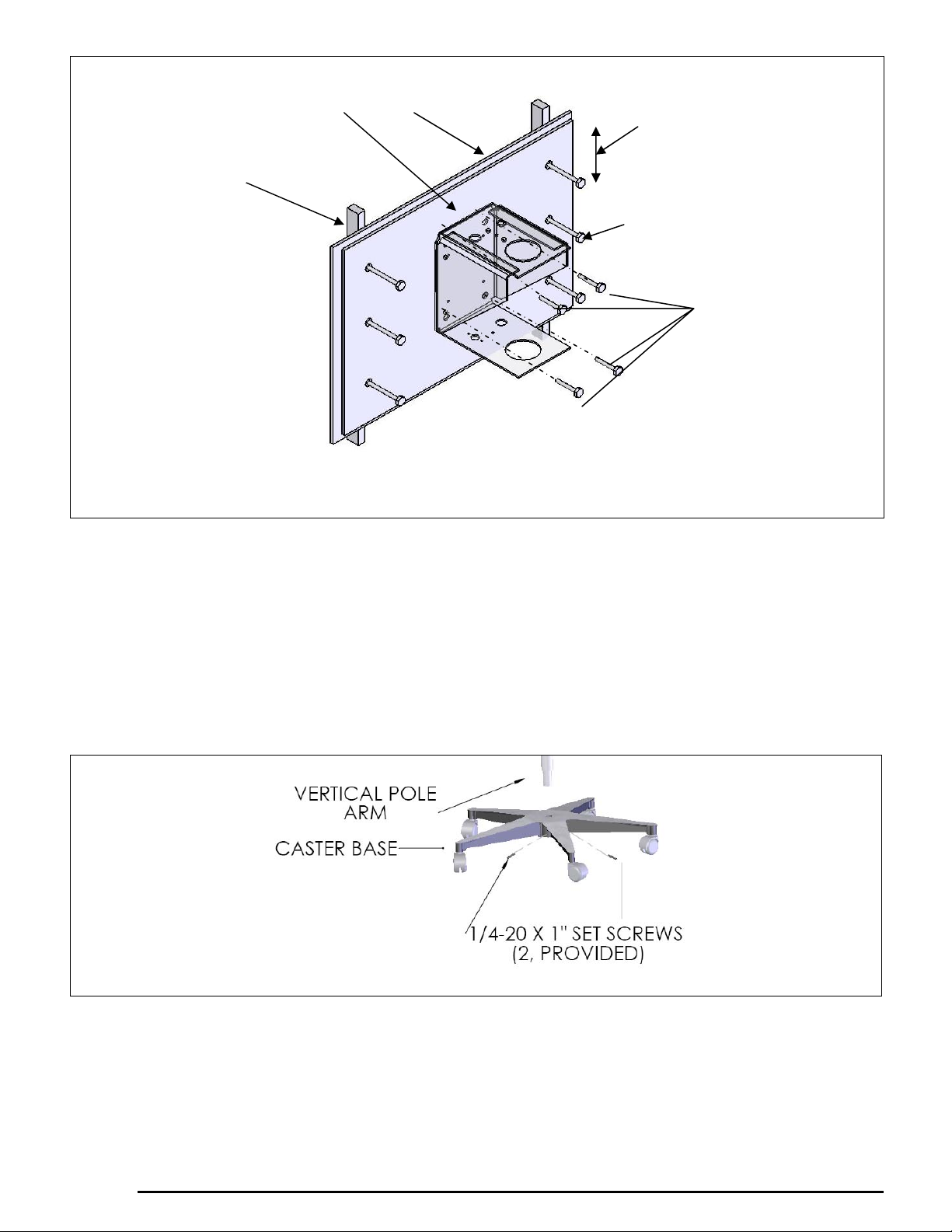
Supplied high
density wall board
Wood or metal stud
CAUTION! Do not use lag
bolts if wall studs are metal.
Appropriate fasteners must be
utilized.
Dry wall
Edge distance (any edge)
1-1/2” (19mm) minimum
1/4” X 5” (M6X13cm) long steel
hex head lag bolts. Minimum 6
required
The bracket is secured to
the wall board. 4 x 3/8”
(M10) bolts.
Figure 14
4. Place the wall board in position and secure through the wall to the wooden wall studs, using six
lag bolts. CAUTION! EACH LAG BOLT MUST BE CAPABLE OF RESISTING PULL OUT
AND SHEAR FORCES OF 100 POUNDS (45kg).
5. Ensure the Extension U-arm is level.
6. Follow instructions in section 5.2 (Items 5 thru 9) to complete the balance arm assembly.
5.6 Installation Instructions (Mobile Light)
1. Insert the bottom of the vertical pole arm into the center housing of the caster base. Secure the
vertical pole with the two (2) provided (1/4-20 X 1”) set screws using provided Allen wrench.
Figure 15
2. Follow instructions in section 5.2 (items 5 thru 9) to complete the light assembly.
INSTALLATION AND OPERATING MANUAL
18
Page 20
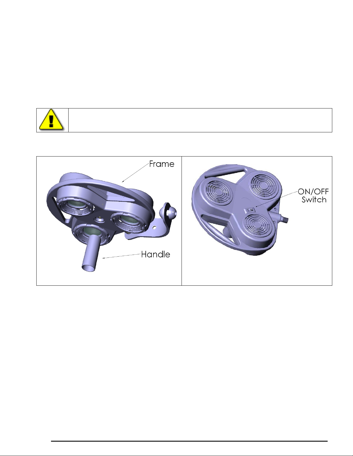
6. Operating Instructions
1. After successful assembly of your light, plug the Hospital Grade plug into an appropriate
Hospital Grade outlet. Do not use three-to-two prong adapters that are not grounded.
2. Turn on your light with the rocker switch in the back cover of the lamp head. (If a wall switch
is also in use, be sure to have the rocker switch to off position before turning the wall switch
on.)
CAUTION: IF A WALL DIMMER IS USED WITH THE LIGHT, IT VOIDS
CERTIFICATION LISTING OF THE PRODUCT. NO DIMMERS ARE APPROVED
TO BE USED WITH THIS LIGHT.
Figure 17
Figure 16
RANGES OF MOTION (REFER TO FIGURE 18)
EXTENSION ARM /BALANCE ARM MOVEMENT: The balance arm moves 340 degrees
both horizontally and vertically at its junction with the extension arm.
LAMP HEAD/YOKE & YOKE/BALANCE ARM MOVEMENT: The lamp head rotates 340
degrees at its connection to the yoke. The yoke rotates 560 degrees at its connection to the balance
arm. The two co-act to provide unlimited choices for beam positioning. All axis of rotation have
very little resistance and no force is needed or should be used to rotate the light.
REACH: With the lamp head/balance arm fully extended in the horizontal plane, the reach from
the center of the ceiling “Z” extension arm to beam center is 58” (1.5m).
CEILING EXTENSION ARM MOVEMENT: The ceiling “Z” extension arm rotates 700
degrees. There is a built-in rotation stop which limits rotary movement in either direction.
19
INSTALLATION AND OPERATING MANUAL
Page 21
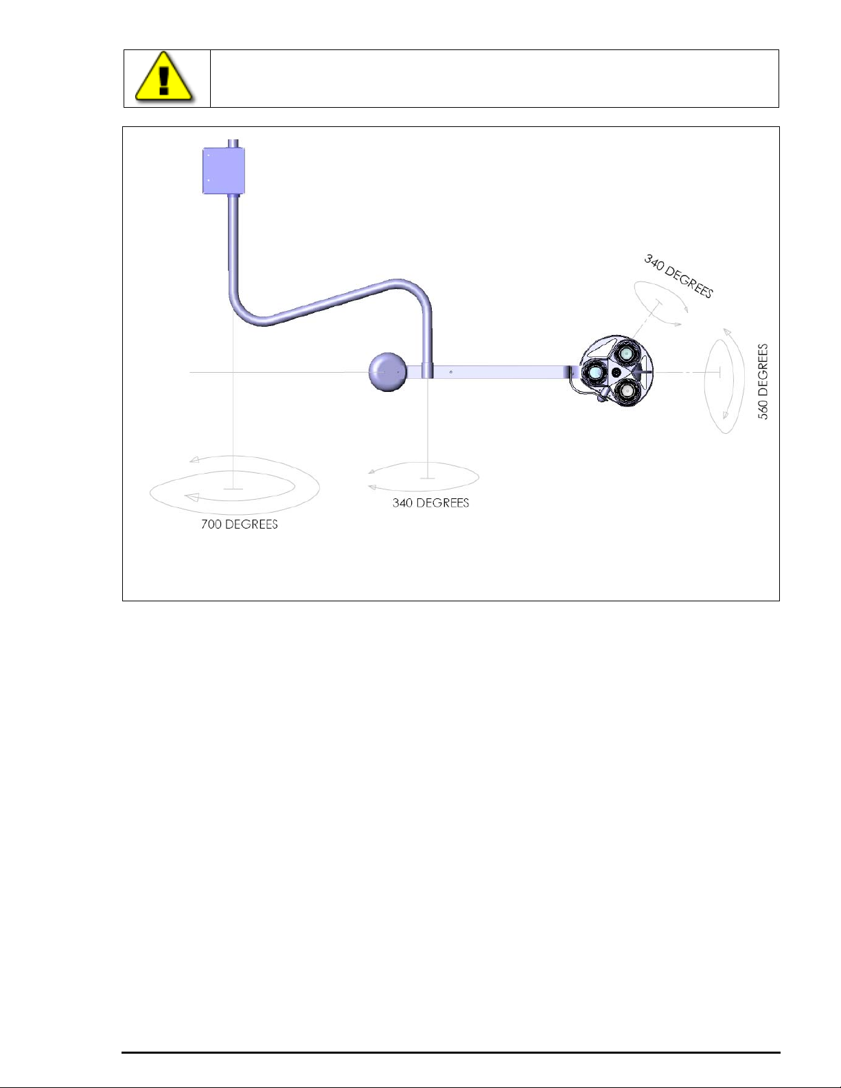
CAUTION! DO NOT FORCE MOVEMENT PAST ITS STOP
POSITION.
Figure 18
Ceiling Light (Ranges of Motion)
7. Maintenance
While your lamp light has been designed to provide you many hours of professional performance,
it will benefit from your periodic care and concern.
7.1 Cleaning and Disinfection
• The covers and frame may easily be cleaned with a soft damp cloth of a mild soap water
solution or mineral spirits.
• Isopropyl alcohol is another acceptable cleansing agent. The front glass filters can be
cleaned with any commercial glass cleaner.
• The metal components are powder coated for long life and can be cleaned with a damp
cloth of mild soap and water solution, mineral spirits or, isopropyl alcohol.
• Periodically dust the backside louvers to ensure uninterrupted convection of ambient air.
This air movement also cools the three lamp/reflector assemblies, further extending their
effectiveness and useful life.
7.2 Handle Autoclaving
• The Delrin handles may be sterilized as any stainless steel instruments.
• Although it is of sufficient diameter to engage a disposable sleeve, it is recommended that
it is treated as a stainless steel item when submitting it to sterilization process below:
INSTALLATION AND OPERATING MANUAL
20
Page 22

1. A flash cycle at 275 – 279O F (135 – 137O C), for 16 minutes
2. A standard cycle at 275 – 279O F (135 – 137O C), for 4 minutes
7.3 Bulb Replacement
CAUTION: ONLY USE OSRAM/SYLVANIA TRU-AIM TITAN BULBS
(DICHROIC, 12V/35W/10°), ANY DEVIATION FROM THESE
INSTRUCTIONS MAY SERIOUSLY DAMAGE YOUR LIGHT. 35WATTS
IS MAXIMUM ALLOWABLE.
Should you experience a bulb failure, ALLOW SUFFICIENT TIME FOR IT TO COOL BEFORE
ATTEMPTING A REPLACEMENT. Once cool, you should:
1. Refer to figures 19, 20 & 21. Turn the lamp head over so the three glass assemblies face
upward.
2. With one hand supporting the backside of the lamp, grasp the notched ring assembly (1)
and twist it counter clockwise.
3. Grasp the bulb with one hand and unplug socket connector with the other.
4. The notched ring assembly may now be removed from the lamp head and placed face down
on a flat surface.
5. Hold the notched ring assembly with thumbs and place two index fingers at flat part of
spring (two red lines in figure 21), pull the spring towards you pulling it out from the slot
(keep other two ends of spring inside its holes).
6. Remove old bulb.
7. Install new bulb. Do not touch inside reflector surface of bulb, always grasp from bulb
outside edges.
8. Close the retainer spring on the bulb by inserting the front tab of spring in the slot (using
index fingers), so that it fits properly. Check to ensure proper seating of the spring, by
pulling on the bulb. [Position (1) in figure 21 is “CLOSED SPRING”]. Ensure that two
open ends of spring are properly seated into holes in the notched ring assembly.
9. Reconnect plug socket to bulb.
10. Replace the notched ring assembly in the lamp head by aligning the three guide projections
into the slots on the lamp head. Refer to figure 20. Press gently inward as you twist the
assembly clockwise. You will hit a stop and set in place. Before turning the lamp head
over, BE POSITIVE THE ASSEMBLY IS PROPERLY SEATED by comparing it with the
other two.
11. The light is now ready for use.
21
INSTALLATION AND OPERATING MANUAL
Page 23
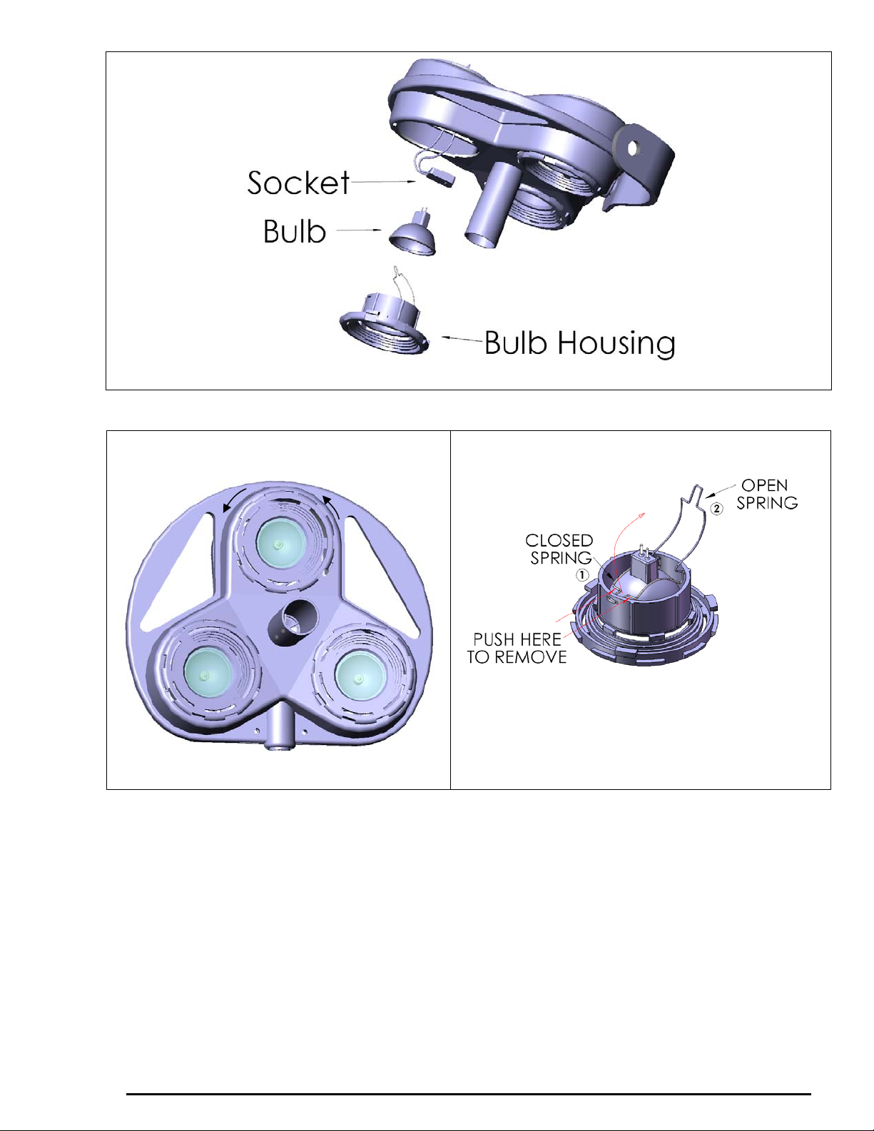
ROTATE
COUNTER-CLOCKWISE
Figure 20. Bulb Replacement - 2
Figure 19. Bulb Replacement - 1
Figure 21. Bulb Replacement - 3
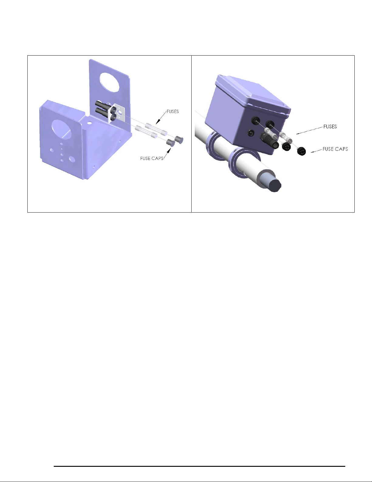
7.4 Fuse Replacement
1. Refer to figures 22 & 23. Remove the plug from outlet.
2. Locate two fuse blocks.
Ceiling and Wall Models: Unscrew the plastic screws from transformer cover. Take off
the transformer cover. Locate fuse holders (2) inside the transformer housing.
Mobile Models: Locate two fuse blocks on the bottom of the transformer housing.
3. Push in and turn the fuse holder counter clockwise. Remove the fuse holder from the fuse
block.
4. Remove and replace the fuse. A blown fuse may not be noticeably different from a good
one. BOTH FUSES SHOULD BE REPLACED AT THE SAME TIME.
5. Follow procedure in reverse to return lamp to operating condition.
6. Fuse Replacement Specifications:
a. USA : Sunnex part# 18565 (2 AMP, 250V, 1/4” X 1-1/4”)
INSTALLATION AND OPERATING MANUAL
22
Page 24
MUST USE A SLOW-BLOW FUSE
b. Europe: Sunnex part# 18641 (1.25 AMP, 250V, 5mm X 20mm)
MUST USE A SLOW-BLOW FUSE
Figure 22
Ceiling/Wall Fuse location
Figure 23
Mobile Fuse location
8. Warranty
8.1 Limited Warranty.
Sunnex warrants that the Product, if properly used, will be free from defects in material and
workmanship, for a period of three (3) years from the date of shipment to Customer. This Limited
Warranty extends only to the original buyer. If the Product is determined to be defective within the
warranty period, Sunnex, at its option, will repair or replace the Product, at no charge or refund the thencurrent value of the Product.
8.2 Disclaimers and Limitations.
This Limited Warranty shall be the sole remedy of Customer and the sole liability of Sunnex to
Customer.
This Limited Warranty does not extend or apply to any defects, failures or damage due to or
resulting from: (a) acts of God, accident, misuse, use of the Product other than its normal and
customary manner, abuse or negligence; (b) everyday wear and tear; (c) alteration or modification
of, or to any part of, the Product; (d) improper operation and maintenance; or (d) any repairs or
attempted repairs by anyone other than Sunnex. This Limited Warranty does not cover any
products sold AS IS or WITH ALL FAULTS. This Limited Warranty excludes the replacement of
bulbs for the Product.
TO THE FULL EXTENT PERMITTED BY APPLICABLE LAW, THIS LIMITED
WARRANTY REPLACES ALL OTHER WARRANTIES OR CONDITIONS, EXPRESS OR
IMPLIED INCLUDING, WITHOUT LIMITATION, ANY AND ALL IMPLIED WARRANTIES
OF MERCHANTABILITY AND FITNESS FOR A PARTICULAR PURPOSE. SUNNEX
DISCLAIMS ALL OTHER WARRANTIES AND CONDITIONS, EXPRESS OR IMPLIED,
INCLUDING, WITHOUT LIMITATION, IMPLIED WARRANTIES OF TITLE,
NONINFRINGEMENT, ABSENCE OF LIENS OR INCUMBRANCES,
23
INSTALLATION AND OPERATING MANUAL
Page 25

MERCHANTABILITY AND FITNESS FOR A PARTICULAR PURPOSE, REGARDLESS OF
WHETHER SUNNEX KNOWS OR HAS REASON TO KNOW OF CUSTOMER’S
PARTICULAR NEEDS. IF IMPLIED WARRANTIES MAY NOT BE DISCLAIMED UNDER
APPLICABLE LAW, THEN ANY IMPLIED WARRANTIES THAT MAY BE IMPOSED BY
LAW ARE LIMITED IN DURATION TO THE LIMITED WARRANTY PERIOD SET FORTH
HEREIN, AND THEREAFTER ANY IMPLIED WARRANTIES ARE EXPRESSLY
DISCLAIMED.
No employee, agent, dealer, reseller or distributor of Sunnex is authorized to modify this Limited
Warranty, or to make any additional warranties.
REPAIR, REPLACEMENT OR REFUND, AS PROVIDED UNDER THIS LIMITED
WARRANTY, ARE CUSTOMER’S SOLE AND EXCLUSIVE REMEDIES. IN NO EVENT
SHALL SUNNEX BE LIABLE FOR ANY DIRECT, INDIRECT, SPECIAL, INCIDENTAL,
CONSEQUENTIAL OR TORT DAMAGES OR LOSSES, WHETHER TO PERSON OR
PROPERTY, INCLUDING DEATH, ARISING OUT OF OR RESULTING FROM ANY
BREACH OF WARRANTY OR ANY OTHER LEGAL THEORY, OR ARISING OUT OF OR
IN CONNECTION WITH THE PRODUCT OR CUSTOMER’S USE OF THE PRODUCT,
EVEN IF SUNNEX IS ADVISED OF THE POSSIBILITY OF SUCH DAMAGES. IN ANY
EVENT, THE TOTAL LIABILITY OF SUNNEX TO YOU FOR ANY CAUSE WHATSOEVER
SHALL BE LIMITED TO THE PURCHASE PRICE YOU PAID FOR THE PRODUCT. THIS
LIMITATION SHALL APPLY REGARDLESS OF THE FORM OF ACTION, WHETHER IN
CONTRACT OR TORT (INCLUDING, WITHOUT LIMITATION, NEGLIGENCE).
SOME STATES DO NOT ALLOW THE EXCLUSION OR LIMITATION OF INCIDENTAL
OR CONSEQUENTIAL DAMAGES, OR ALLOW LIMITATIONS ON HOW LONG AN
IMPLIED WARRANTY LASTS, SO THE ABOVE LIMITATIONS OR EXCLUSIONS MAY
NOT APPLY TO YOU. THIS LIMITED WARRANTY GIVES YOU SPECIFIC LEGAL
RIGHTS, AND YOU MAY ALSO HAVE OTHER RIGHTS THAT VARY FROM STATE TO
STATE.
8.3 Claims Procedure.
(a) Customer must contact Sunnex at (800)-445-7869 with a request for warranty service or to report a
technical issue. Sunnex Technical Support will attempt to identify, diagnose and resolve the reported
problem via the telephone.
(b) If attempts by Sunnex to resolve a reported problem are unsuccessful, Customer will then be
provided with a Customer-specific Returned Merchandise Authorization number (“RMA ”). The RMA
number must be noted on any correspondence to Sunnex and displayed prominently on the outside
packaging of any Product shipped to Sunnex.
(c) Within ten (10) days of receipt of the RMA number, Custom er m u st s hi p t he Pr od uc t t o Su n nex at
Customer’s expense (insuring the Product is recommended) in either its o riginal packaging or pack aging
affording an equal degree of protection, to Sunnex Inc. 3 Huron Drive, Natick MA 01760, with a
statement describing the problem in reasonable specificity. Proof of purchase must be included to
obtain warranty service. Sunnex will not be held responsible for shipping damages that occur in transit.
Any damage to the Product during shipping will not be covered under this Limited Warranty and shall
be subject to a service charge.
(d) Subject to the limitations specified herein, upon receipt, Sunnex will inspect the ship ped Product
and, at its sole discretion, repair or replace the Prod uct with th e same or a like product to the exten t it
does not conform to this Limited Warranty. In the event Sunnex, at its sole discretion, opts to replace the
Product, should said product be discontinued or no longer be offered for sale by Sunnex, a like product
in design and functionality will be provided to Customer.
24
INSTALLATION AND OPERATING MANUAL
Page 26

(e) Sunnex will ship the repaired Product or a replacement to Custom er within ten (10) business days
after receipt from the date tha t Sunnex receives the Product. Standard shipments to the Customer will
be paid by Sunnex. Sunnex assumes no responsibility for shipment delays by the carrier.
(f) If Customer requires warranty service to be provided in less than ten (10) business days, but not less
than three (3) business days, Sunnex will charge Customer an additional One Hundred Dollars
($100.00) express handling charge per request for each Product.
8.4 Customer Responsibilities.
(a) To validated warranty customer is required to fill out online or provided warranty card.
(b) Customer is required to follow the user manual associated with the Product for proper
operation.
(c) Customer is required to perform periodic preventive maintenance as called for in the user
manual associated with the Product.
(d) Any modifications or repairs made to the Product without prior written authorization from
Sunnex will render this Limited Warranty null and void. Instances whereby this is determined to
be the case by Sunnex technical staff will be subject to an initial service charge of $75.00 ($25.00
evaluation charge and $50.00 minimum labor cost).
8.5 Miscellaneous.
In the event that any provision of this Limited Warranty should be or becomes invalid and/or
unenforceable during the warranty period, the remaining provisions shall continue in full force and
effect.
The provisions of this Limited Warranty shall be governed by the laws of the Commonwealth of
Massachusetts without regard to its conflict of laws principles. This Limited Warranty shall not be
modified except by an agreement signed by both parties specifically referencing this Limited
Warranty.
This Limited Warranty represents the entire agreement between Sunnex and Customer with respect
to the subject matter herein and supersedes all prior or contemporaneous oral or written
communications, representations, understandings or agreements relating to this subject.
For service assistance or resolution of a service problem, or for Product or warranty information,
write to Sunnex Inc. 3 Huron Drive, Natick MA 01760, or visit www.sunnex.com
.
8.6 Optional Extended Limited Warranty Plan.
The purchase of the Optional Extended Limited Warranty extends the duration of this Limited
Warranty from a period of three (3) years to a period of five (5) years from the date of shipment to
Customer. The Optional Limited Warranty may be purchased at the time of the original purchase
of the Product or the Extended Limited Warranty to become effective and apply to the Product.
Customer must pay the appropriate Extended Limited Warranty fee and upon initial purchase,
register each Product with Sunnex within thirty (30) days from the date of shipment to Customer
by Sunnex, or a Sunnex authorized dealer or reseller.
Sunnex Customer Service
Sunnex Inc, USA + 1 508 651 0009
Sunnex Equipment AB Sweden + 46 565 177 00
Warranty + 1 508 651 0009
25
INSTALLATION AND OPERATING MANUAL
Page 27
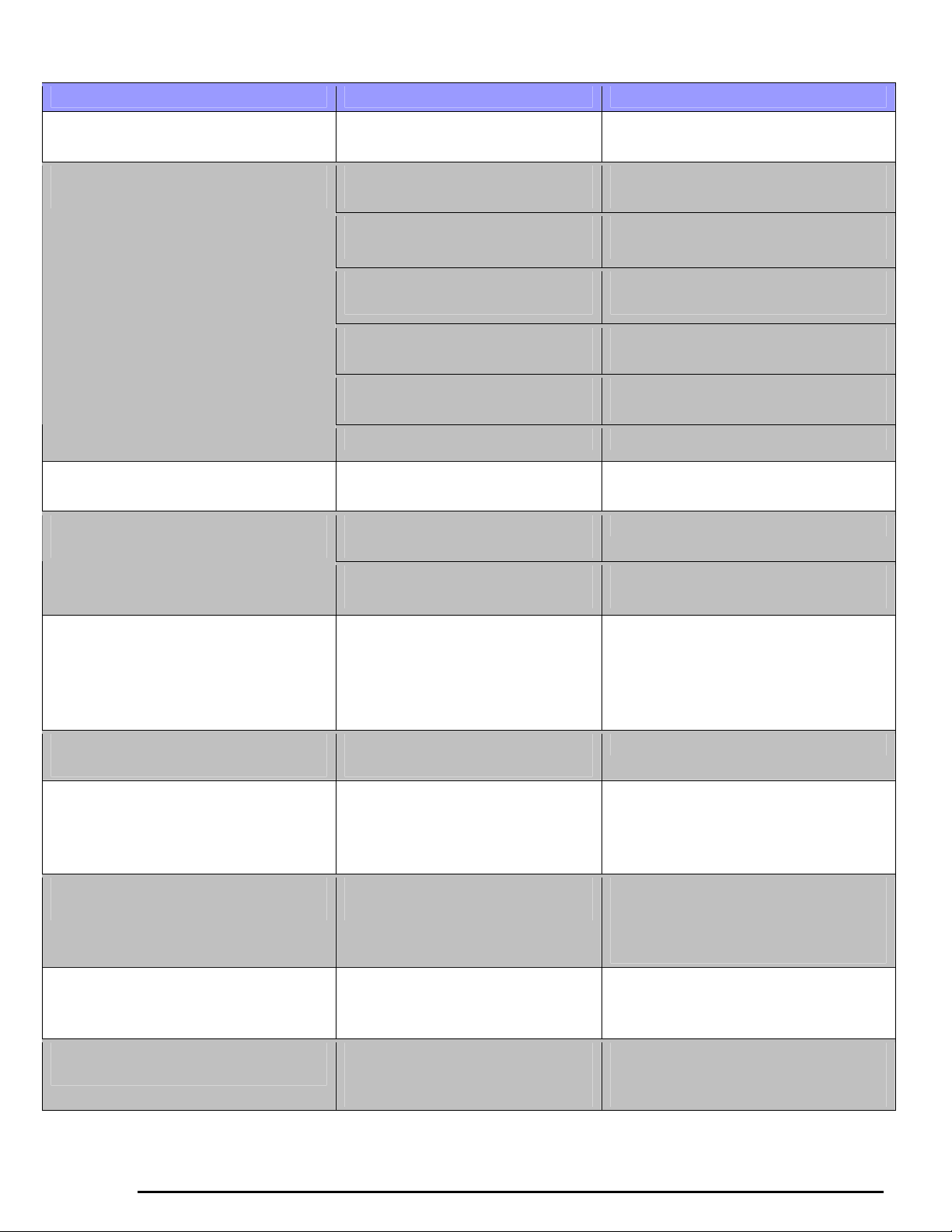
9. Troubleshooting
PROBLEM POSSIBLE CAUSE SOLUTION
No light from light head Light head switch is on OFF
position
No light from light head, when
ON/OFF switch is ON
Connection at balance arm and
extension arm not correct
Bulb has not been installed or it
has burned out
Fuse is blown
No power to the transformer box Check for facility power to the
Transformer is malfunctioning
Incorrect bulb installed Install correct bulb
Bulb burns out quickly Incorrect bulb installed in the
light head
Incorrect bulb installed in the
or intensity
light head
Bulb/reflector is not seated in its
holder correctly
Turn on the ON/OFF switch to ON
position
Check the connection
Refer to bulb replacement procedure
in the manual
Replace BOTH FUSES following
the fuse replacement procedure
transformer box
Check for 14 V AC output at the
transformer when it is under load
Install correct bulb
Install correct bulb Light output is irregular in its shape
Adjust the bulb/reflector so it seats
in the holder properly
No light from light head even when
the bulb and fuse are in good
condition, light head flashes
intermittently when light head or
arms are moved
Head & balance arm drift (moves
down) slightly
Extension arm does not rotate freely
or drifts (Ceiling)
Extension arm does not rotate freely
or drifts (Wall)
Balance arm does not rotate freely
or drifts when released in desired
position
Light head does not rotate freely at
lamp head/yoke joint
Circuit or wiring problem within
transformer, arm assemblies or
other part of lighting system
Normal wear in leather antisqueak washer
Improper installation of the
ceiling bracket
Improper installation of the wall
board on wall studs of the room
The nut joining the balance arm
and the extension arm is loose
The screw/nut joining lamp head
with the yoke is too tight or too
loose
INSTALLATION AND OPERATING MANUAL
Check all wiring connections. If
problem cannot be repaired, call
Customer Service
GENTLY tighten balance arm nut
Check for excessive flexing of
ceiling support structure and check
if ceiling plate is level. Readjust if
necessary.
Check the joint of transformer
housing with wall board, and wall
board with wall studs. Readjust if
necessary.
Tighten this nut slightly
Tighten/loosen as appropriate until
free movement of lamp head is
achieved
26
Page 28
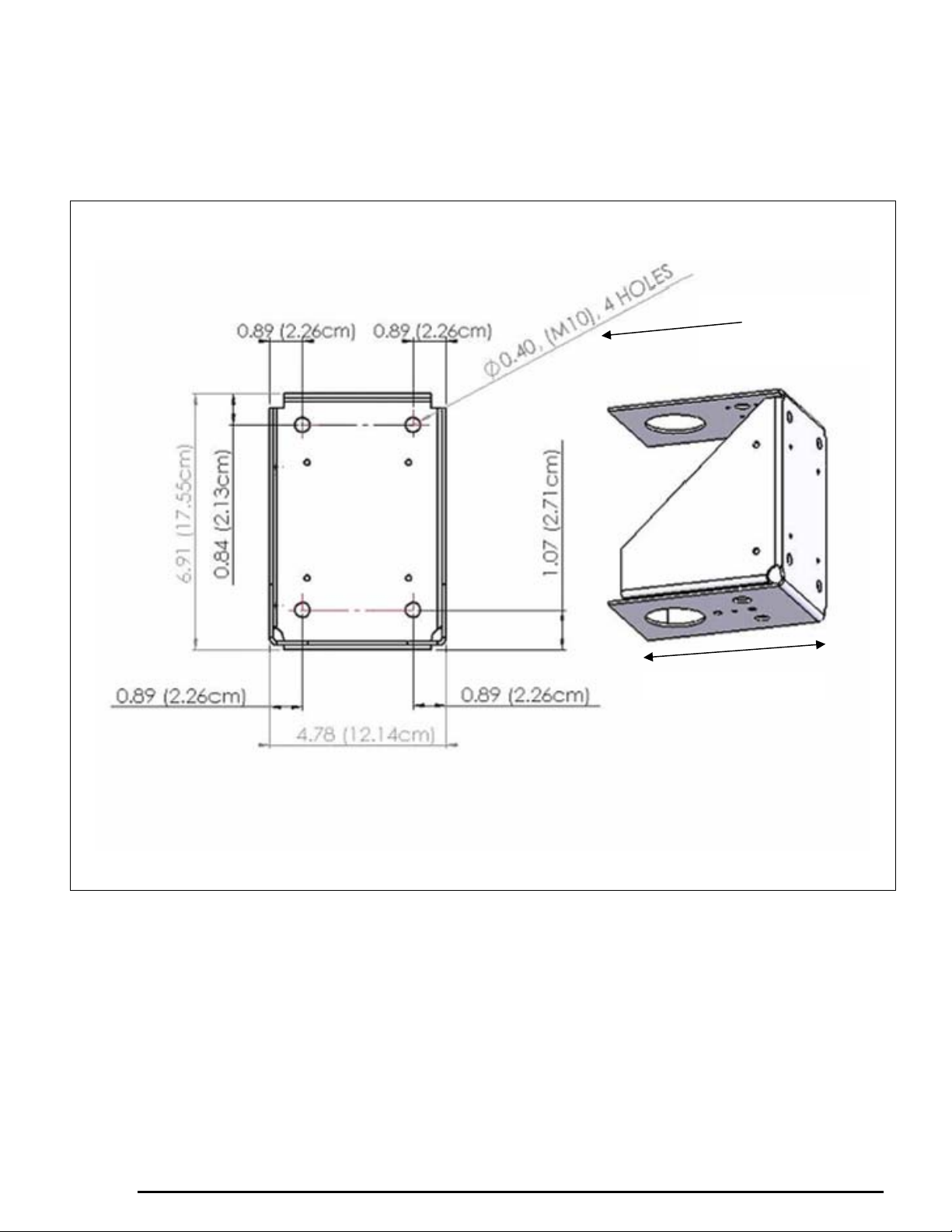
10. Appendix
Appendix A: TRANSFORMER HOUSING (CEILING, DUAL & WALL)
DIMENSIONS
MOUNTING
HOLES
”
INSTALLATION AND OPERATING MANUAL
27
Page 29
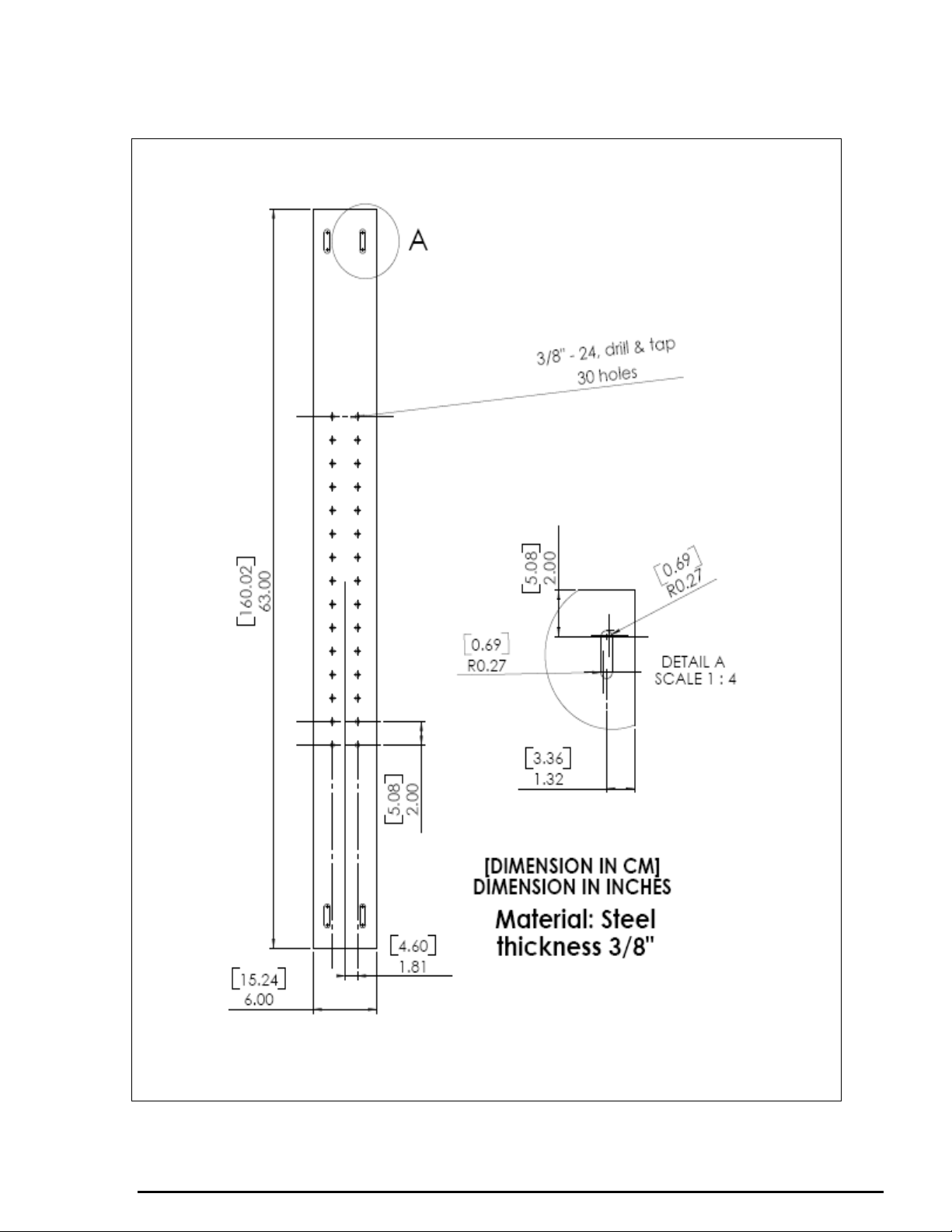
Appendix B: OPTIONAL STEEL STRUCTURE
PART# 18750
HORIZONTAL PLATE
(OPTIONAL, TO BE PURCHASED SEPARATELY)
INSTALLATION AND OPERATING MANUAL
28
Page 30
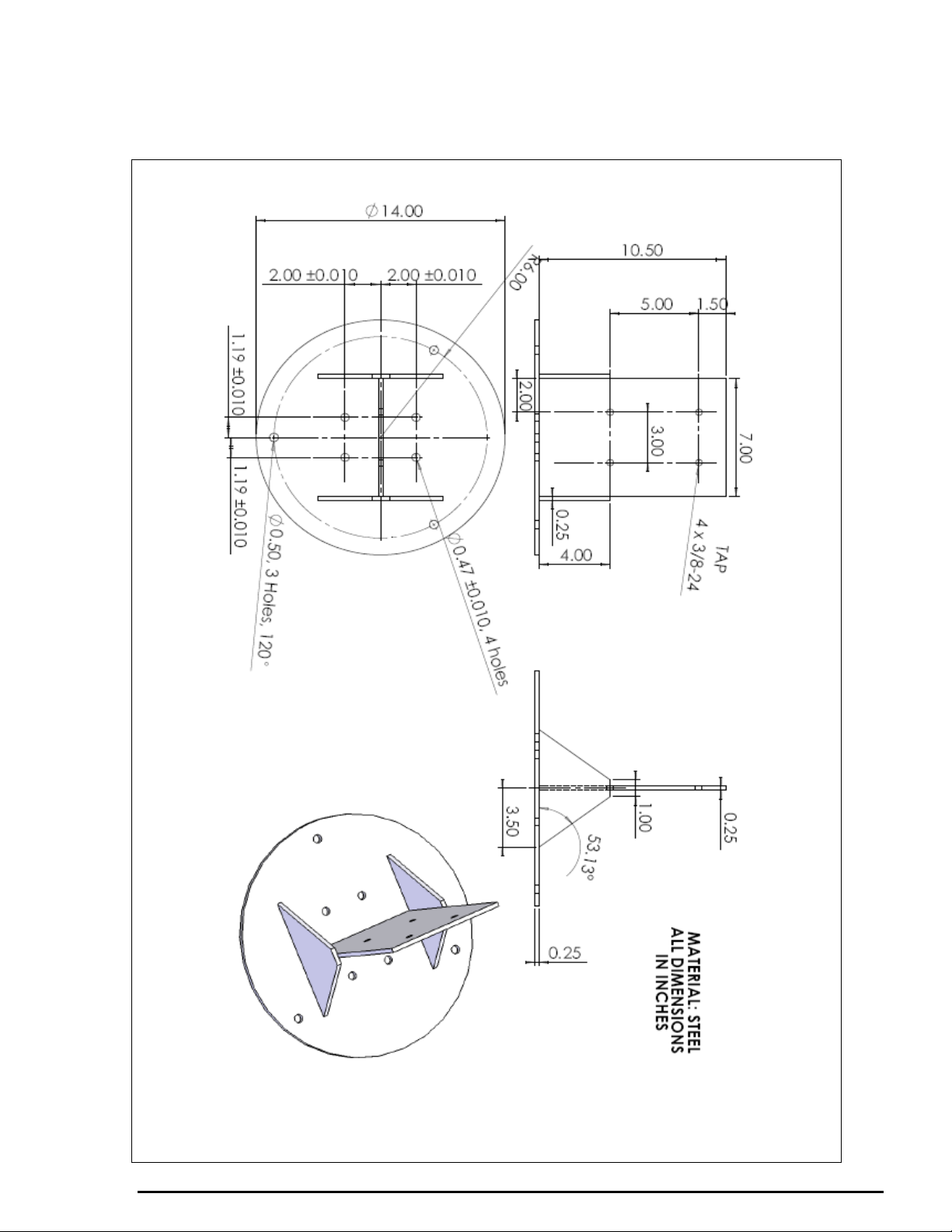
APPENDIX C: DUAL MOUNT SEISMIC BRACKET
PART# 18523
OR 4 X 0.394”
holes
SEISMIC BRACKET
(COMES STANDARD WITH DUAL LIGHTS ONLY)
MUST BE PURCHASED SEPARATELY FOR SINGLE CEILING LIGHT
INSTALLATION AND OPERATING MANUAL
29
Page 31

PRODUCT SPECIFICATIONS SUBJECT TO CHANGE WITHOUT NOTICE
INSTALLATION AND OPERATING MANUAL
30
Page 32

WWW.SUNNEXMEDICAL.COM
_______________________________________________________________________
Sunnex, Inc.
3 Huron Drive
Natick, MA 01760-1314
USA
Tel: + 1 800 445 7869
Fax: 1 508 651 0099
Email: [email protected]
Sunnex Equipment AB
Box 8064
SE-163 08 Spånga
Sweden
Tel: + 46 8 546 802 30
Fax: + 46 8 546 802 59
Email: [email protected]
Sunnex is certified ISO
9001:2008 by
Sunnex Equipment Sarl
Zl. Les Milles B.P. 154 000
13794 Aix en Provence, Cedex 3
France
Tel: + 33 442 39 78 96
Fax: + 33 442 39 78 77
Email: [email protected]
INSTALLATION AND OPERATING MANUAL
Sunnex GmbH
Ricarda-Huch-Str. 2
D-14480 Potsdam
Germany
Tel: + 49 331 600 77 27
Fax: + 49 331 600 77 63
Email: [email protected]
REVISION 3.3
MARCH 2010
 Loading...