

Page 1

Sun ZFS Storage 7120, 7320, and 7420
Appliance Installation Guide
Part No: E38245
December 2012 E38245–01
Page 2

Copyright © 2009, 2011, 2012, Oracle and/or its aliates. All rights reserved.
This software and related documentation are provided under a license agreement containing restrictions on use and disclosure and are protected by intellectual
property laws. Except as expressly permitted in your license agreement or allowed by law, you may not use, copy, reproduce, translate, broadcast, modify, license,
transmit, distribute, exhibit, perform, publish or display any part, in any form, or by any means. Reverse engineering, disassembly, or decompilation of this software,
unless required by law for interoperability, is prohibited.
The information contained herein is subject to change without notice and is not warranted to be error-free. Ifyou nd any errors, please report them to us in writing.
If this is software or related documentation that is delivered to the U.S. Government or anyone licensing it on behalf of the U.S. Government, the following notice is
applicable:
U.S. GOVERNMENT END USERS. Oracle programs, including any operating system, integrated software, any programs installed on the hardware, and/or
documentation, delivered to U.S. Government end users are "commercial computer software" pursuant to the applicable Federal Acquisition Regulation and
agency-specic supplemental regulations. As such, use, duplication, disclosure, modication, and adaptation of the programs, including any operating system,
integrated software, any programs installed on the hardware, and/or documentation, shall be subject to license terms and license restrictions applicable to the
programs. No other rights are grantedto the U.S. Government.
This software or hardware is developed for general use in a variety of information management applications. It is not developed or intended for use in any inherently
dangerous applications, including applications that may create a risk of personal injury. If you use this software or hardware in dangerous applications, then you shall
be responsible to take all appropriate fail-safe, backup, redundancy, and other measures to ensure its safe use. Oracle Corporation and its aliates disclaim any
liability for any damages caused by use of this software or hardware in dangerous applications.
Oracle and Java are registered trademarks of Oracle and/or its aliates. Other names may be trademarks of their respective owners.
Intel and Intel Xeon are trademarks or registered trademarks of Intel Corporation. All SPARC trademarks are used under license and are trademarks or registered
trademarks of SPARC International, Inc. AMD, Opteron, the AMD logo, and the AMD Opteron logo are trademarks or registered trademarks of Advanced Micro
Devices. UNIX is a registered trademark of The Open Group.
This software or hardware and documentation may provide access to or information on content, products, and services from third parties. Oracle Corporation and
its aliates are not responsible for and expressly disclaim all warranties of any kind with respect to third-party content, products, and services. Oracle Corporation
and its aliates will not be responsible for any loss, costs, or damages incurred due to your access to or use of third-party content, products, or services.
Ce logiciel et la documentation qui l’accompagnesont protégés par les lois sur la propriété intellectuelle. Ils sont concédés sous licence et soumis à des restrictions
d’utilisation et de divulgation. Sauf disposition de votre contrat de licence ou de la loi, vous ne pouvez pas copier, reproduire, traduire, diuser, modier, breveter,
transmettre, distribuer, exposer, exécuter, publier ou acher le logiciel, même partiellement, sous quelque forme et par quelque procédé que ce soit. Par ailleurs, il est
interdit de procéder à toute ingénierie inverse du logiciel, de le désassembler ou de le décompiler, excepté à des ns d’interopérabilité avec des logiciels tiers ou tel que
prescrit par la loi.
Les informations fournies dans ce document sont susceptibles de modication sanspréavis. Par ailleurs, Oracle Corporation ne garantit pas qu’elles soient exemptes
d’erreurs et vous invite, le cas échéant, à lui en faire part par écrit.
Si ce logiciel, ou la documentation qui l’accompagne,est concédé sous licence au Gouvernement des Etats-Unis, ou à toute entité qui délivre la licence de ce logiciel
ou l’utilise pour le compte du Gouvernement des Etats-Unis, la notice suivante s’applique :
U.S. GOVERNMENT END USERS. Oracle programs, including any operating system, integrated software, any programs installed on the hardware, and/or
documentation, delivered to U.S. Government end users are "commercial computer software" pursuant to the applicable Federal Acquisition Regulation and
agency-specic supplemental regulations. As such, use, duplication, disclosure, modication, and adaptation of the programs, including any operating system,
integrated software, any programs installed on the hardware, and/or documentation, shall be subject to license terms and license restrictions applicable to the
programs. No other rights are grantedto the U.S. Government.
Ce logiciel ou matériel a été développé pour un usage général dans le cadre d’applications de gestion des informations. Ce logiciel ou matériel n’est pas conçu ni n’est
destiné à être utilisé dans des applications à risque, notamment dans des applications pouvant causer des dommages corporels. Si vous utilisez ce logiciel ou matériel
dans le cadre d’applications dangereuses, il est de votre responsabilité de prendre toutes les mesures de secours, de sauvegarde, de redondance et autres mesures
nécessaires à son utilisation dans des conditions optimales de sécurité. Oracle Corporation et ses aliés déclinent toute responsabilité quant aux dommages causés
par l’utilisation de ce logiciel ou matériel pour ce type d’applications.
Oracle et Java sont des marques déposées d’OracleCorporation et/ou de ses aliés.Tout autre nom mentionné peut correspondre à des marques appartenant à
d’autrespropriétairesqu’Oracle.
Intel Xeon sont des marques ou des marques déposées d'Intel Corporation. Toutes les marques SPARCsontutilisées sous licence et sont des marques ou des marques
déposées de SPARC International, Inc. AMD, Opteron, le logo AMD et le logo AMD Opteron sont des marques ou des marques déposées d'Advanced Micro Devices.
UNIX est une marque déposée d'The Open Group.
Ce logiciel ou matériel et la documentation qui l'accompagne peuvent fournir des informations ou des liens donnant accès à des contenus, des produits et des services
émanant de tiers. Oracle Corporation et ses aliés déclinent toute responsabilité ou garantie expresse quant aux contenus, produits ou services émanant de tiers. En
aucun cas, Oracle Corporation et ses aliés ne sauraient être tenus pour responsables des pertes subies, des coûts occasionnés ou des dommages causés par l'accès à
des contenus, produits ou services tiers, ou à leur utilisation.
121219@25097
Page 3

Contents
Preface .....................................................................................................................................................7
1 Introduction ...........................................................................................................................................9
Overview ..................................................................................................................................................9
Introduction ....................................................................................................................................9
2 Installation ............................................................................................................................................13
Installation ........................................................................................................................................... 13
Introduction ................................................................................................................................. 13
Overview ............................................................................................................................................... 14
Precautions ................................................................................................................................... 14
Prerequisites ................................................................................................................................. 14
Controller, Cabinet and Disk Shelf Installation Tasks ............................................................ 15
7x20 Controllers .................................................................................................................................. 15
7x20 Controller Installation Tasks ............................................................................................. 15
Prerequisites ................................................................................................................................. 15
Tools and Equipment Needed .................................................................................................... 16
Tasks .............................................................................................................................................. 16
DE2 24C ................................................................................................................................................ 29
Precautions ................................................................................................................................... 29
Prerequisites ................................................................................................................................. 30
Tools and Equipment Needed .................................................................................................... 30
Tasks .............................................................................................................................................. 30
DE2 24P ................................................................................................................................................ 37
Precautions ................................................................................................................................... 37
Prerequisites ................................................................................................................................. 37
Tools and Equipment Needed .................................................................................................... 38
3
Page 4

Tasks .............................................................................................................................................. 38
Sun Disk Shelf ...................................................................................................................................... 45
Precautions ................................................................................................................................... 45
Prerequisites ................................................................................................................................. 45
Tools and Equipment Needed .................................................................................................... 45
Tasks .............................................................................................................................................. 46
3 Cabling ..................................................................................................................................................51
Cabling .................................................................................................................................................. 51
Cabling Diagrams ........................................................................................................................ 51
7120 Cabling ........................................................................................................................................ 52
Connecting Sun Disk Shelves/J4x00s to the Sun ZFS Storage 7120 ....................................... 52
7320 Cabling ........................................................................................................................................ 54
Connecting Sun Disk Shelves/J4x00s to the Sun ZFS Storage 7320 ....................................... 54
7320 Cluster Cabling ........................................................................................................................... 56
Connecting Sun Disk Shelves/J4x00s to the Sun ZFS Storage 7320 Cluster ......................... 56
7420 Cabling pt.1 ................................................................................................................................. 58
Connecting Sun Disk Shelves/J4x00s to the Sun ZFS Storage 7420 (2 HBAs) ...................... 58
7420 Cabling pt.2 ................................................................................................................................. 60
Connecting Sun Disk Shelves/J4x00s to the Sun ZFS Storage 7420 (3 HBAs) ...................... 60
7420 Cabling pt.3 ................................................................................................................................. 62
Connecting Sun Disk Shelves/J4x00s to the Sun ZFS Storage 7420 (4 HBAs) ...................... 62
7420 Cabling pt.4 ................................................................................................................................. 65
Connecting Sun Disk Shelves/J4x00s to the Sun ZFS Storage 7420 (5 HBAs) ...................... 65
7420 Cabling pt.5 ................................................................................................................................. 68
Connecting Sun Disk Shelves/J4x00s to the Sun ZFS Storage 7420 (6 HBAs) ...................... 68
7420 Cluster Cabling pt.1 ................................................................................................................... 71
Connecting Sun Disk Shelves/J4x00s to the Sun ZFS Storage 7420 Cluster (2 HBAs) ........ 71
7420 Cluster Cabling pt.2 ................................................................................................................... 74
Connecting Sun Disk Shelves/J4x00s to the Sun ZFS Storage 7420 Cluster (3 HBAs) ........ 74
7420 Cluster Cabling pt.3 ................................................................................................................... 77
Connecting Sun Disk Shelves/J4x00s to the Sun ZFS Storage 7420 Cluster (4 HBAs) ........ 77
7420 Cluster Cabling pt.4 ................................................................................................................... 80
Connecting Sun Disk Shelves/J4x00s to the Sun ZFS Storage 7420 Cluster (5 HBAs) ........ 80
7420 Cluster Cabling pt.5 ................................................................................................................... 83
Contents
Sun ZFS Storage 7120, 7320, and7420 Appliance Installation Guide • December2012E38245–014
Page 5

Connecting Sun Disk Shelves/J4x00s to the Sun ZFS Storage 7420 Cluster (6 HBAs) ........ 83
DE2-24 .................................................................................................................................................. 87
Connecting DE2 Enclosures to the Sun ZFS Storage 7120 ..................................................... 87
DE2-24 .................................................................................................................................................. 89
Connecting DE2 Enclosures to the Sun ZFS Storage 7320 ..................................................... 89
DE2-24 .................................................................................................................................................. 91
Connecting DE2 Enclosures to the Sun ZFS Storage 7320 Cluster ........................................ 91
DE2-24x2 .............................................................................................................................................. 93
Connecting DE2 Enclosures to the Sun ZFS Storage 7420 (2 HBAs) .................................... 93
DE2-24x3 .............................................................................................................................................. 95
Connecting DE2 Enclosures to the Sun ZFS Storage 7420 (3 HBAs) .................................... 95
DE2-24x4 .............................................................................................................................................. 97
Connecting DE2 Enclosures to the Sun ZFS Storage 7420 (4 HBAs) .................................... 97
DE2-24x5 ............................................................................................................................................ 100
Connecting DE2 Enclosures to the Sun ZFS Storage 7420 (5 HBAs) .................................. 100
DE2-24x6 ............................................................................................................................................ 103
Connecting DE2 Enclosures to the Sun ZFS Storage 7420 (6 HBAs) .................................. 103
DE2-24x2 ............................................................................................................................................ 106
Connecting DE2 Enclosures to the Sun ZFS Storage 7420 Cluster (2 HBAs) ..................... 106
DE2-24x3 ............................................................................................................................................ 109
Connecting DE2 Enclosures to the Sun ZFS Storage 7420 Cluster (3 HBAs) ..................... 109
DE2-24x4 ............................................................................................................................................ 112
Connecting DE2 Enclosures to the Sun ZFS Storage 7420 Cluster (4 HBAs) ..................... 112
DE2-24x5 ............................................................................................................................................ 115
Connecting DE2 Enclosures to the Sun ZFS Storage 7420 Cluster (5 HBAs) ..................... 115
DE2-24x6 ............................................................................................................................................ 118
Connecting DE2 Enclosures to the Sun ZFS Storage 7420 Cluster (6 HBAs) ..................... 118
HBA Expansion pt.1 .......................................................................................................................... 122
Expanding from 2 to 3 HBAs .................................................................................................... 122
HBA Expansion pt.2 .......................................................................................................................... 126
Expanding from 3 to 4 HBAs .................................................................................................... 126
HBA Expansion pt.3 .......................................................................................................................... 131
Expanding from 4 to 5 HBAs .................................................................................................... 131
HBA Expansion pt.4 .......................................................................................................................... 135
Expanding from 5 to 6 HBAs .................................................................................................... 135
Contents
5
Page 6

4 PoweringOn and Conguringthe System .................................................................................... 141
Power .................................................................................................................................................. 141
Powering On and Conguring the Appliance ........................................................................ 141
Tasks ............................................................................................................................................ 142
Next Steps .................................................................................................................................... 144
Initial ................................................................................................................................................... 144
Initial Conguration .................................................................................................................. 144
Prerequisites ............................................................................................................................... 145
Summary ..................................................................................................................................... 145
BUI ............................................................................................................................................... 146
CLI ............................................................................................................................................... 146
Update ................................................................................................................................................ 151
Post-Installation Controller Update ........................................................................................ 151
Glossary .............................................................................................................................................. 153
Contents
Sun ZFS Storage 7120, 7320, and7420 Appliance Installation Guide • December2012E38245–016
Page 7

Preface
The Sun ZFS Storage 7x20 Appliance Installation Guide contains installation, cabling and initial
conguration documentation for Oracle's Sun ZFS Storage 7120, 7320, 7420 appliances.
This documentation is also available while using the appliance Browser User Interface (BUI),
accessible via the Help button. The appliance documentation may be updated using the System
Upgrade procedure documented in the System Service Manual.
Who Should Use This Book
This guide is for users and system administrators who install and use the Sun ZFS Storage 7x20
NAS appliances.
Related Documentation
Refer to the following documentation for administration information, hardware overviews,
service procedures and software update notes.
■
Administration Guide, Analytics Guide and Service Manual (http://www.oracle.com/
technetwork/documentation/)
Access to Oracle Support
Oracle customers have access to electronic support through My Oracle Support. For
information, visit
http://www.oracle.com/pls/topic/lookup?ctx=acc&id=info or visit
http://www.oracle.com/pls/topic/lookup?ctx=acc&id=trs if you are hearing impaired.
7
Page 8

8
Page 9

Introduction
Overview
Introduction
The Sun ZFS Storage 7000 family of products provide ecient le and block data services to
clients over a network, and a rich set of data services that can be applied to the data stored on the
system.
Controllers
■
7120
■
7320
■
7420
Legacy platforms: 7110 | 7210 | 7310 | 7410
Expansion Storage
■
Disk Shelves
Legacy platforms: J4400/J4500
1
CHAPTER 1
9
Page 10

Protocols
Sun ZFS Storage appliances include support for a variety of industry-standard client protocols,
including:
■
SMB
■
NFS
■
HTTP and HTTPS
■
WebDAV
■
iSCSI
■
FC
■
SRP
■
iSER
■
FTP
■
SFTP
Key Features
Sun ZFS Storage systems also include new technologies to deliver the best storage
price/performance and unprecedented observability of your workloads in production,
including:
■
Analytics, a system for dynamically observing the behavior of your system in real-time and
viewing data graphically
■
The ZFS Hybrid Storage Pool, composed of optional Flash-memory devices for acceleration
of reads and writes, low-power, high-capacity disks, and DRAM memory, all managed
transparently as a single data hierarchy
Data Services
To manage the data that you export using these protocols, you can congure your Sun ZFS
Storage system using the built-in collection of advanced data services, including:
LICENSE NOTICE: Remote Replication and Cloning may be evaluated free of charge,
but each feature requires that an independent license be purchased separately for use in
production. After the evaluation period, these features must either be licensed or
deactivated. Oracle reserves the right to audit for licensing compliance at any time. For
details, refer to the "Oracle Software LicenseAgreement ("SLA") and Entitlement for
Hardware Systems with Integrated Software Options."
■
RAID-Z (RAID-5 and RAID-6), mirrored, and striped disk congurations
■
Unlimited read-only and read-write snapshots, with snapshot schedules
■
Data deduplication
■
Built-in data compression
■
Remote replication of data for disaster recovery
■
Active-active clustering for high availability (7310, 7320, 7410, and 7420)
Overview
Sun ZFS Storage 7120, 7320, and7420 Appliance Installation Guide • December2012E38245–0110
Page 11

■
Thin provisioning of iSCSI LUNs
■
Virus scanning and quarantine
■
NDMP backup and restore
Availability
To maximize the availability of your data in production, Sun ZFS Storage appliances include a
complete end-to-end architecture for data integrity, including redundancies at every level of the
stack. Key features include:
■
Predictive self-healing and diagnosis of all system hardware failures: CPUs, DRAM, I/O
cards, disks, fans, power supplies
■
ZFS end-to-end data checksums of all data and metadata, protecting data throughout the
stack
■
RAID-6 (double- and triple-parity) and optional RAID-6 across disk shelves
■
Active-active clustering for high availability (7310, 7320, 7410, and 7420)
■
Link aggregations and IP multipathing for network failure protection
■
I/O Multipathing between the controller and disk shelves
■
Integrated software restart of all system software services
■
Phone-Home of telemetry for all software and hardware issues
■
Lights-out Management of each system for remote power control and console access
Browser User Interface (BUI)
The browser user interface
The BUI is the graphical tool for administration of the appliance. The BUI provides an intuitive
environment for administration tasks, visualizing concepts, and analyzing performance data.
Overview
Chapter 1 • Introduction 11
Page 12

The management software is designed to be fully featured and functional on a variety of web
browsers.
Direct your browser to the system using either the IP address or host name you assigned to the
NET-0 port during initial conguration as follows: https://ipaddress:215 or
https://hostname:215. The login screen appears.
The online help linked in the top right of the BUI is context-sensitive. For every top-level and
second-level screen in the BUI, the associated help page appears when you click the Help
button.
Command Line Interface (CLI)
The CLI is designed to mirror the capabilities of the BUI, while also providing a powerful
scripting environment for performing repetitive tasks. The following sections describe details of
the CLI. When navigating through the CLI, there are two principles to be aware of:
■
Tab completion is used extensively: if you are not sure what to type in any given context,
pressing the Tab key will provide you with possible options. Throughout the
documentation, pressing Tab is presented as the word "tab" in bold italics.
■
Help is always available: the help command provides context-specic help. Help on a
particular topic is available by specifying the topic as an argument to help, for example help
commands. Available topics are displayed by tab-completing the help command, or by typing
help topics.
You can combine these two principles, as follows:
dory:> help tab
builtins commands general help properties script
Overview
Sun ZFS Storage 7120, 7320, and7420 Appliance Installation Guide • December2012E38245–0112
Page 13

Installation
Installation
Introduction
This section addresses how to physically install the system chassis into a rack, connect
controllers in a high-availability cluster, and expand storage. The following topics are
described.
■
Overview
■
Controllers
■
7x20 family
■
Expansion Storage
■
Oracle Storage Drive Enclosure DE2-24C
■
Oracle Storage Drive Enclosure DE2-24P
■
Sun Disk Shelf
■
Cabling
■
Powering on
■
Initial conguration
2
CHAPTER 2
13
Page 14

Overview
Precautions
Observe the following cautions when installing any Sun ZFS Storage 7x20 controller or cabinet.
■
Always load equipment into a rack from the bottom up so that it will not become top-heavy
and tip over. Deploy the anti-tip bar to the prevent the rack from tipping during equipment
installation.
■
Ensure that the temperature in the rack does not exceed the controller's maximum ambient
rated temperatures. Consider the total airow requirements of all equipment installed in the
rack to ensure that the equipment is operated within its specied temperature range.
■
For best results, only qualied Oracle service personnel should perform cluster installation
and conguration. Contact Oracle Service for assistance.
Prerequisites
Refer to the Quick Setup poster that shipped with the product or the following hardware service
sections for an overview of your system controller or cabinet.
■
7120 Overview - view component diagrams and specications
■
7320 Overview - view component diagrams and specications, and cluster options
■
7420 Overview - view component diagrams, specications, and cluster options
If you intend to install disk shelves into the same rack, refer to the Disk Shelf Installation section
for how to install them into the bottom of your rack.
Legacy platform overviews are provided in the 7110 Overview, 7210 Overview, 7310 Overview,
7410 Overview online sections.
For controller installation, check that your rack is compatible with the slide rail and cable
management assembly options as follows:
■
The structure is a four-post rack with mounting at both front and back. Two-post racks are
not compatible.
■
The horizontal opening and unit vertical pitch conforms to ANSI/EIA 310-D-1992 or IEC
60927 standards.
■
The distance between the front and back mounting planes is between 24 in and 36 in (610
mm to 915 mm).
■
The distance to the front cabinet door, providing clearance depth in front of the front
mounting plane, is at least 1 in (25.4 mm).
Overview
Sun ZFS Storage 7120, 7320, and7420 Appliance Installation Guide • December2012E38245–0114
Page 15

■
The distance to the back cabinet door, providing clearance depth behind the front mounting
plane, is at least 31.5 in (800 mm) with the cable management assembly, or 27.5 in (700 mm)
without the cable management assembly.
■
The distance between structural supports and cable troughs, providing clearance width
between the front and back mounting planes, is at least 18 in (456 mm).
For cabinet installation, you will need a total distance of at least 15 ft/4.5 m for safe maneuvering
when you roll the cabinet o the shipping pallet.
Controller, Cabinet and Disk Shelf InstallationTasks
The following sections provide installation tasks with enumerated steps.
■
7x20 controller installation tasks
■
Disk shelf installation tasks
■
7x10 controller installation tasks (see online section)
7x20 Controllers
7x20 Controller Installation Tasks
This section provides enumerated steps for installing the Sun ZFS Storage 7120, 7320 or 7420
controllers into a rack using the rail assembly in the rack mount kit. Note that if your rack
mount kit shipped with installation instructions, use those instructions instead.
Observe the following cautions:
■
Always load equipment into a rack from the bottom up so that it will not become top-heavy
and tip over. Deploy the anti-tip bar to the prevent the rack from tipping during equipment
installation.
■
Ensure that the temperature in the rack will not exceed the controller's maximum ambient
rated temperatures. Consider the total airow requirements of all equipment installed in the
rack to ensure that the equipment is operated within its specied temperature range.
Prerequisites
Refer to the Quick Setup poster that shipped with the product or the following sections for an
overview of your controller.
■
7120 Overview - view component diagrams and specications
■
7320 Overview - view component diagrams and specications
7x20 Controllers
Chapter 2 • Installation 15
Page 16

■
7420 Overview - view component diagrams and specications
Tools and Equipment Needed
To install the system, you need the following tools:
■
No. 2 Phillips screwdriver
■
ESD mat and grounding strap
■
Pencil, stylus, or other pointed device, for pushing front panel buttons
You also need a system console device, such as one of the following:
■
Sun workstation
■
ASCII terminal
■
Terminal server
■
Patch panel connected to a terminal server
Tasks
7x20 ControllersTasks
▼
Installing Mounting Bracketson the Controller Chassis
If the mounting brackets are shipped inside the slide rails, you must remove them before
beginning this procedure, as follows.
■
Unpack the slide rails and locate the slide rail lock at the front of the assembly.
■
Squeeze and hold the tabs at top and bottom of the lock (1) while you pull the mounting
bracket out to the stop.
■
Push the mounting bracket release button toward the front of the mounting bracket (2)
while withdrawing the bracket from the assembly.
The following graphic illustrates the procedure for disassembling the 7120/7320 rail kit.
7x20 Controllers
Sun ZFS Storage 7120, 7320, and7420 Appliance Installation Guide • December2012E38245–0116
Page 17

The following graphic illustrates the procedure for disassembling the 7420 rail kit.
7x20 Controllers
Chapter 2 • Installation 17
Page 18

Position a mountingbracket against the chassis so that the slide rail lock is at the front of the
chassis, and the keyed openings on the mounting bracket are alignedwith the locating pins on
the side of the chassis.
The following graphic illustrates how to attach the 7120/7320 mounting brackets.
1
7x20 Controllers
Sun ZFS Storage 7120, 7320, and7420 Appliance Installation Guide • December2012E38245–0118
Page 19

The following graphic illustrates how to attach the 7420 mounting brackets.
With the heads of the four chassis locatingpins protruding though the four keyedopenings in
the mounting bracket,pull the mounting-bracket toward the front of the chassis until the
mounting-bracket clip locks into place with an audible click.
Verify that all mounting pins aresecurely fastened to the chassis.
Repeat to install the remaining mounting bracket on the other side of the chassis.
▼
Installing the ControllerChassis into the Rack Slide Rails
This procedure requires a minimum of two people because of the weight of the chassis.
Attempting this procedure alone could result in equipment damage or personal injury. Always
load equipment into rack from the bottom up.
2
3
4
7x20 Controllers
Chapter 2 • Installation 19
Page 20

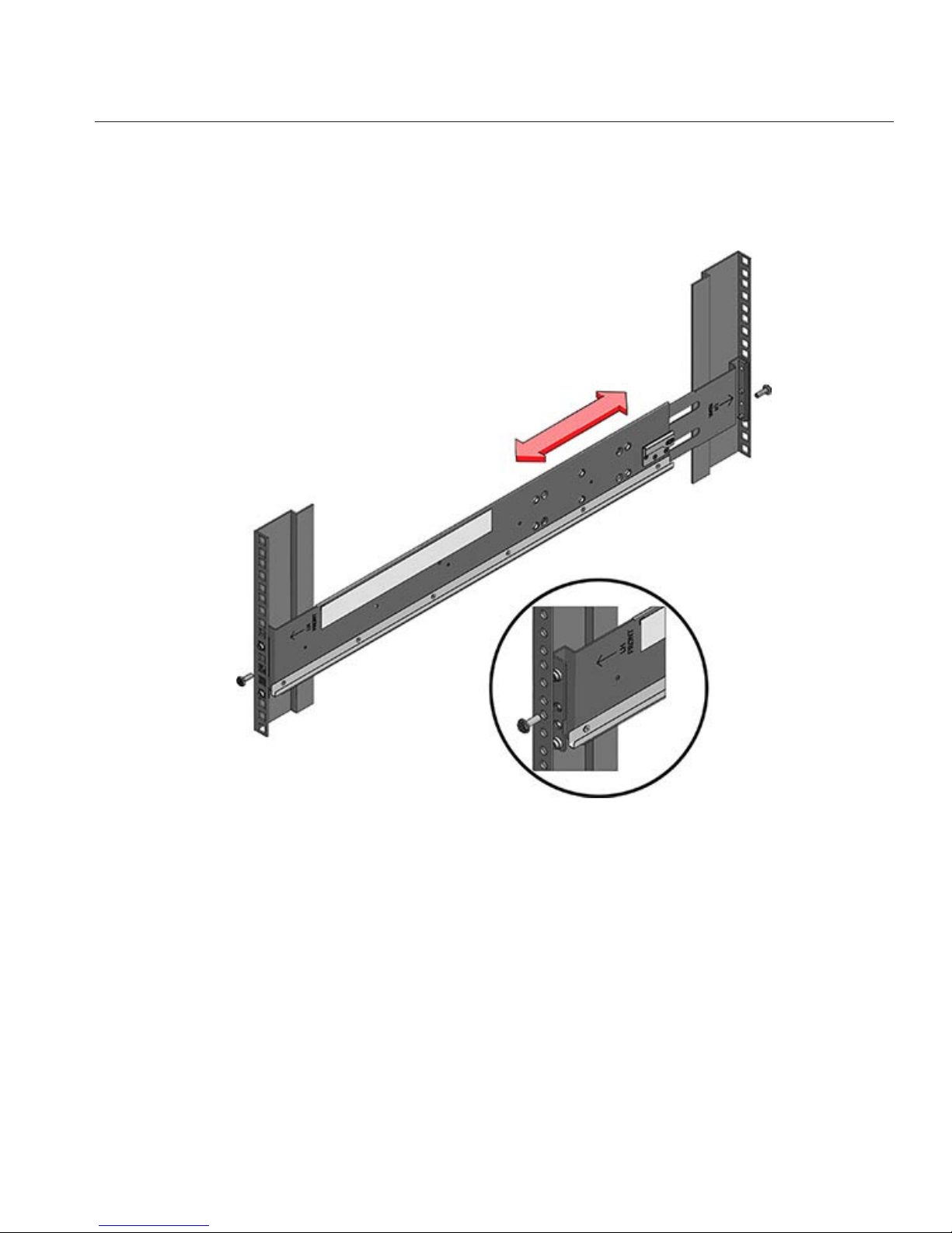
If you areusing a universal 19-inch cabinet, snap an M6 square cage nut into the top and bottom
holes of the location whereyou will be installing the rail plate as shown.
Position a sliderail assembly in your rack so that thebrackets at each end of the slide rail
assembly are on the outsideof the front and backrack posts. The followinggraphic illustrates
1
2
7x20 Controllers
Sun ZFS Storage 7120, 7320, and7420 Appliance Installation Guide • December2012E38245–0120
Page 21

the rail assembly brackets.
Attach each slide rail assembly to the rack posts, but do not tightenthe screws completely.3
7x20 Controllers
Chapter 2 • Installation 21
Page 22

From the front of the rack, set the proper width of the railswith the rail-width spacer (1).
Tighten the screwson the brackets.
Remove the spacerand conrm that the rails are attached tightly to the rack.
4
5
6
7x20 Controllers
Sun ZFS Storage 7120, 7320, and7420 Appliance Installation Guide • December2012E38245–0122
Page 23

If your rack includes an anti-tip foot, extend it from the bottom of the rack.
Lower the rack stabilization feet if you have not already done so.
Push the slide rails into the slide rail assemblies in the rack as far as possible.
7
8
9
7x20 Controllers
Chapter 2 • Installation 23
Page 24

Raise the chassis so that the back ends of the mounting bracketsare aligned with the slide rail
and insertthe chassis into the slide rails, pushing the chassis slowly, until the mounting brackets
meet the slide rail stops(~12 in or 30 cm).You will hear an audible click.
The following graphic illustrates the 7120/7320 chassis insertion and slide rail locks usage.
10
7x20 Controllers
Sun ZFS Storage 7120, 7320, and7420 Appliance Installation Guide • December2012E38245–0124
Page 25

The following graphic illustrates 7420 chassis insertion.
▼
Installing the Cable Management Assembly
This procedure is completed from the back of the equipment rack.
7x20 Controllers
Chapter 2 • Installation 25
Page 26

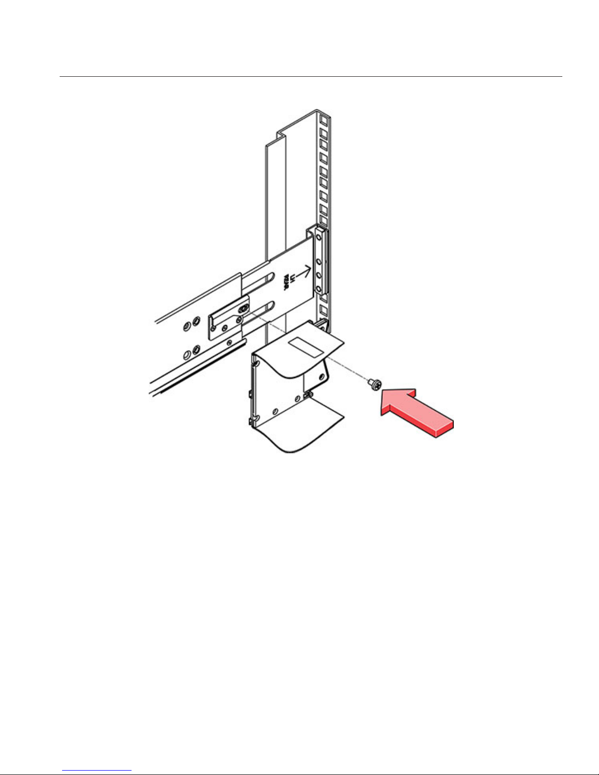
Attach the cable management assembly (CMA) rail extension to the left slide railuntil the
extension locks into place.
Insert the CMA mounting bracket connector intothe right slide rail until the connector locks
into place.
1
2
7x20 Controllers
Sun ZFS Storage 7120, 7320, and7420 Appliance Installation Guide • December2012E38245–0126
Page 27

Insert the right CMA slide rail connector (1) into the right slide rail assembly (2) until the
connector locks into place.
3
7x20 Controllers
Chapter 2 • Installation 27
Page 28

Insert the left CMA slide rail connector (1) intothe rail extension on theleft slide rail assembly
(2) until the connector locks into place.
4
7x20 Controllers
Sun ZFS Storage 7120, 7320, and7420 Appliance Installation Guide • December2012E38245–0128
Page 29

After you install and route the cables throughthe assembly, attach the hook and loop straps (1)
to secure the cables. Then attach the right andleft outer latches to support the assembly.
DE2 24C
Precautions
Observe the following cautions when installing the Oracle Storage Drive Enclosure DE2-24C
into a rack using the supplied rail kit. Note that if your rail kit shipped with installation
instructions, use those instructions instead.
■
Always load equipment into a rack from the bottom up so that it will not become top-heavy
and tip over. Deploy the anti-tip bar to prevent the rack from tipping during equipment
installation.
■
Ensure that the temperature in the rack does not exceed the controller's maximum ambient
rated temperatures. Consider the total airow requirements of all equipment installed in the
rack to ensure that the equipment is operated within its specied temperature range.
■
Do not remove a component if you do not have an immediate replacement. The disk shelf
must not be operated without all components in place.
5
DE2 24C
Chapter 2 • Installation 29
Page 30

■
Do not lift the disk shelf by the handles on the power supply with fan modules; they are not
designed to take the weight.
Prerequisites
Refer to the following section for an overview of your disk shelf.
■
Disk Shelf Overview - view component diagrams and specications
Tools and Equipment Needed
To install the shelf, you need the following tools:
■
Phillips head No. 2 screwdriver that is a minimum of 4 inches long.
■
A mechanical lift is highly recommended because the chassis can weigh approximately 110
lbs (50 kg). At least three people are required: two to install the shelf and one spotter to
engage the rails.
■
If a mechanical lift is not available, remove the power supply with fan modules to reduce the
weight, see Disk Shelf Maintenance Procedures for instructions.
Use one of the following racks for the disk shelf:
■
Sun Rack II 1042/1242 cabinet
■
Any 19-inch wide, 4-post, EIA-compatible rack or cabinet with a front-to-back depth
between vertical cabinet rails of 61 cm to 91 cm (24 in. to 36 in.). The cabinet can have
threaded or unthreaded cabinet rails. Threaded cabinets must be M6 or 10-32 cabinets.
Cabinets must be able to support the weight of all equipment contained within them.
Position the rack where the shelf is to be installed adjacent to the rack where the controller is
installed, if separate. Stabilize the cabinet and lock the casters. To facilitate access, remove doors
from cabinets.
Tasks
Installing the Disk Shelf into the Rack Slide Rails
1. The Oracle Storage Drive Enclosure DE2-24C requires four standard mounting units (4RU)
of vertical space in the cabinet. Starting at the bottom of the cabinet, locate the appropriate
rack unit (RU) height. Install disk shelves below controllers to prevent the rack from
tipping.
DE2 24C
Sun ZFS Storage 7120, 7320, and7420 Appliance Installation Guide • December2012E38245–0130
Page 31

2. If using an unthreaded universal 19-inch or Sun Rack II cabinet, snap one supplied cage nut
into the 8th rack hole, counting upward, in each front rail of the 4RU space.
3. Prepare the screws in each rail end:
Square-hole unthreaded cabinet: No preparation.
Round-hole unthreaded cabinet: Remove the screws from each rail end and discard.
Locate the 8 screws with washers for round-hole cabinets and place aside.
Threaded cabinet: Remove screws and replace them in the opposite direction (from the
inside of the rail ange) so they act as location pins.
4. Position the front of the rails inside the cabinet, with the rail ange inside of the cabinet
ange, and the rail label facing the inside of the cabinet.
Square-hole unthreaded cabinet: The screw heads t inside the rack holes.
Round-hole unthreaded cabinet: Install two screws with at and spring washers through
the rack and into the front of each rail. Do not install into the cage nut in the rack, or the clip
nut on the rail.
DE2 24C
Chapter 2 • Installation 31
Page 32

Threaded cabinet: The location pins t inside the rack holes.
5. Adjust the rail lengths to t.
6. Install one screw, plain washer, and spring washer through the rack and into the rear of each
rail.
DE2 24C
Sun ZFS Storage 7120, 7320, and7420 Appliance Installation Guide • December2012E38245–0132
Page 33

7. Tighten the two locking screws in the rails.
8. Using a mechanical lift or two people, one at each side of the disk shelf, carefully lift and rest
the shelf on the bottom ledge of the left and right rails.
DE2 24C
Chapter 2 • Installation 33
Page 34

9. Do not lift using the power supply handles.
10. Carefully slide the shelf into the cabinet. Ensure that the shelf is fully seated within the rails.
If removing the shelf to reseat it, support it at all times.
11. Remove the front side caps, install two screws, two plain washers, and two spring washers
into each front side, and replace the caps.
DE2 24C
Sun ZFS Storage 7120, 7320, and7420 Appliance Installation Guide • December2012E38245–0134
Page 35

12. Install one long patchlock screw per rail to secure the rear of the shelf to the rear of the rack.
13. Connect and supply power to the disk shelf as described in the next section.
Powering On the Disk Shelf
Ensure you have met the following electrical safety measures before applying power to the disk
shelf:
■
Provide a suitable power source with electrical overload protection to meet the power
supply input voltage range of 100-240 VAC, 50-60 Hz. The disk shelves are compatible with
100-120 VACor 200-240 VAC sources. The power source must not be overloaded by the
total number of disk shelves in the cabinet. At full load, each DE2-24 draws 1,140W, and
each Sun Disk Shelf draws 912W.
■
The power source must provide a reliable earth connection for each disk shelf and the
cabinet.
■
Ensure that the power source is easily accessible because the power cord is the main
disconnect device for the disk shelf.
DE2 24C
Chapter 2 • Installation 35
Page 36

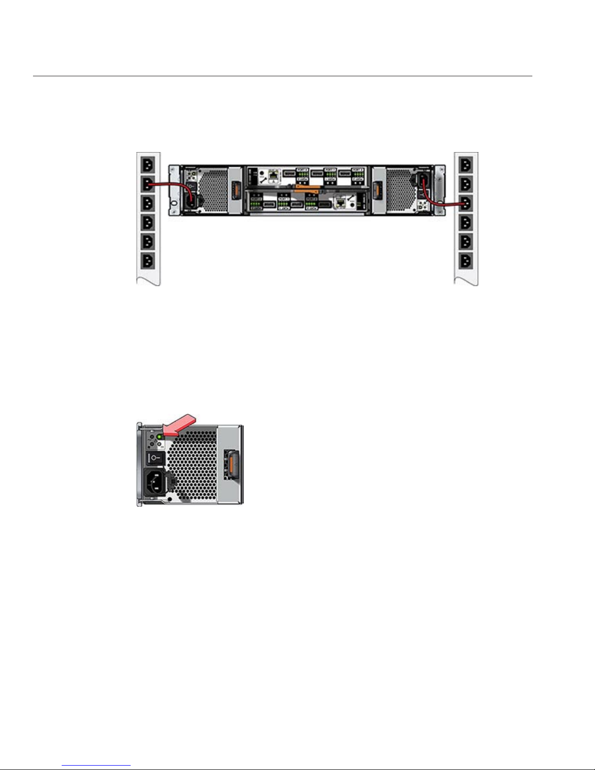
1. Plug a power cord into each power supply with fan module.
2. Plug the other end of the power cords into the external power source for the cabinet.Note:
To guarantee redundancy, power cords must be connected to two separate and independent
power sources.
3. Supply power to the external power source.
4. Place the power supply on/o switches to the "I" on position.
5. Turn on the cabinet circuit breakers, if applicable.
6. After the disk shelf powers on, which could take several minutes, ensure that the system
power indicator on the front of the disk shelf is lit a steady green, and that each power supply
with fan module status indicator on the rear is lit a steady green. If not, power o the disk
shelf as described in the next section and reseat the faulted module. If the module status
indicator is not a steady green after module reinsertion, contact Oracle Customer Service.
7. Perform the software setup tasks as described in the storage controller installation guide.
Powering O the Disk Shelf
Most disk shelf components are hot-swappable; you do not need to remove power when
replacing them. Do not remove a component if you do not have an immediate replacement. The
disk shelf must not be operated without all components in place.
Powering o or removing all SAS chains from a disk shelf will cause the controller(s) to panic to
prevent data loss, unless the shelf is part of an NSPF (no single point of failure) data pool. To
avoid this, shut down the controller(s) before decommissioning the shelf. For details on NSPF
proles, see Prole Conguration.
DE2 24C
Sun ZFS Storage 7120, 7320, and7420 Appliance Installation Guide • December2012E38245–0136
Page 37

1. Stop all input and output to and from the disk shelf.
2. Wait approximately two minutes until all disk activity indicators have stopped ashing.
3. Place the power supply on/o switches to the "O" o position.
4. Disconnect the power cords from the external power source for the cabinet.Note: All power
cords must be disconnected to completely remove power from the disk shelf.
See Also
■
Cabling Diagrams
DE2 24P
Precautions
Observe the following cautions when installing the Oracle Storage Drive Enclosure DE2-24P
into a rack using the supplied rail kit. Note that if your rail kit shipped with installation
instructions, use those instructions instead.
■
Always load equipment into a rack from the bottom up so that it will not become top-heavy
and tip over. Deploy the anti-tip bar to prevent the rack from tipping during equipment
installation.
■
Ensure that the temperature in the rack does not exceed the controller's maximum ambient
rated temperatures. Consider the total airow requirements of all equipment installed in the
rack to ensure that the equipment is operated within its specied temperature range.
■
Do not remove a component if you do not have an immediate replacement. The disk shelf
must not be operated without all components in place.
■
Do not lift the disk shelf by the handles on the power supply with fan modules; they are not
designed to take the weight.
Prerequisites
Refer to the following section for an overview of your disk shelf.
■
Disk Shelf Overview - view component diagrams and specications
DE2 24P
Chapter 2 • Installation 37
Page 38

Tools and Equipment Needed
To install the shelf, you need the following tools:
■
Phillips head No. 2 screwdriver that is a minimum of 4 inches long.
■
T20 Torx driver if using a threaded cabinet.
■
A mechanical lift is highly recommended because the chassis can weigh approximately 51
lbs (23 kg). At least three people are required: two to install the shelf and one spotter to
engage the rails.
Use one of the following racks for the disk shelf:
■
Sun Rack II 1042/1242 cabinet
■
Any 19-inch wide, 4-post, EIA-compatible rack or cabinet with a front-to-back depth
between vertical cabinet rails of 61 cm to 91 cm (24 in. to 36 in.). The cabinet can have
threaded or unthreaded cabinet rails. Threaded cabinets must be M6 or 10-32 cabinets.
Cabinets must be able to support the weight of all equipment contained within them.
Position the rack where the shelf is to be installed adjacent to the rack where the controller is
installed, if separate. Stabilize the cabinet and lock the casters. To facilitate access, remove doors
from cabinets.
Tasks
DE2 24PTasks
▼
Installing the Disk Shelf into the Rack Slide Rails
The Oracle StorageDrive Enclosure DE2-24P requires two standardmounting units (2RU) of
vertical space in the cabinet.Starting atthe bottom of the cabinet, locate the appropriate rack
unit (RU) height, which issix rack holes. Install diskshelves below controllersto prevent rack
from tipping.
Install the rails into the cabinet.
For an unthreaded universal 19-inch or Sun Rack II cabinet:
a) Position the front rail location pegs fully inside the appropriate holes in the front of the rack.
The rail ange must be inside of the cabinet ange, and the rail label facing the inside of the
cabinet.
b) Insert and loosely tighten one screw through the front of the rack and into the top hole in the
rails.
1
2
DE2 24P
Sun ZFS Storage 7120, 7320, and7420 Appliance Installation Guide • December2012E38245–0138
Page 39
c) Adjust the rail lengths to t, and position the rear rail location pegs in the corresponding rear
rack holes.
d) Insert and loosely tighten one screw through the back of the rack and into the back of the
rails.
For a threaded universal 19-inch cabinet:
a) Use the T20 Torx driver to remove the rail location pegs from the front and rear of the rails.
DE2 24P
Chapter 2 • Installation 39
Page 40

b) Use the supplied wrench to insert two pins into each end of the rails, in the same location
where the location pegs were removed.
c) Position the front of the rails inside the cabinet, with the rail ange inside of the cabinet
ange, and the rail label facing the inside of the cabinet. The pins should be fully located within
the rack holes.
d) Insert and loosely tighten one screw through the front of the rack and into the top hole in the
rails.
e) Adjust the rail lengths to t, and locate the rear pins inside the corresponding rear rack holes.
DE2 24P
Sun ZFS Storage 7120, 7320, and7420 Appliance Installation Guide • December2012E38245–0140
Page 41

f) Insert and loosely tighten one screw through the back of the rack and into the back of the rails.
Using a mechanical lift or two people, one at each side of the disk shelf, carefully lift and rest the
shelf on the bottom ledgeof the left and right rails. Do not lift using the powersupply with fan
3
DE2 24P
Chapter 2 • Installation 41
Page 42

module handles.
Carefully slide the shelf into the rails until it is fully seated within the cabinet. Ensure that the
shelf is fully seated within the rails. If removing the shelf to reseat it, support it at all times.
Remove the diskshelf approximately 7.87 in. (200 mm).
Tighten all fourscrews that were previouslyinserted and loosely tightened in the rails.
Fully insert the disk shelf again, and check that the shelf is still fully seated within the rails.
Remove the frontside caps, install one screw into each frontside, and replacethe caps.
4
5
6
7
8
DE2 24P
Sun ZFS Storage 7120, 7320, and7420 Appliance Installation Guide • December2012E38245–0142
Page 43
Install one long patchlock screw per rail tosecure the rear of the shelf to the rear of the rack.
Connect and apply power to the disk shelf as described in the next section.
Powering On the Disk Shelf
Ensure you have met the following electrical safety measures before applying power to the disk
shelf:
■
Provide a suitable power source with electrical overload protection to meet the power
supply input voltage range of 100-240 VAC, 50-60 Hz. The disk shelves are compatible with
100-120 VACor 200-240 VAC sources. The power source must not be overloaded by the
total number of disk shelves in the cabinet. At full load, each DE2-24 draws 1,140W, and
each Sun Disk Shelf draws 912W.
■
The power source must provide a reliable earth connection for each disk shelf and the
cabinet.
■
Ensure that the power source is easily accessible because the power cord is the main
disconnect device for the disk shelf.
9
10
DE2 24P
Chapter 2 • Installation 43
Page 44
1. Plug a power cord into each power supply with fan module.
2. Plug the other end of the power cords into the external power source for the cabinet.Note:
To guarantee redundancy, power cords must be connected to two separate and independent
power sources.
3. Apply power to the external power source.
4. Place the power supply on/o switches to the "I" on position.
5. Turn on the cabinet circuit breakers, if applicable.
6. After the disk shelf powers on, which could take several minutes, ensure that the system
power indicator on the front of the disk shelf is lit a steady green, and that each power supply
with fan module status indicator on the rear is lit a steady green. If not, power o the disk
shelf as described in the next section and reseat the faulted module. If the module status
indicator is not a steady green after module reinsertion, contact Oracle Customer Service.
7. Perform the software setup tasks as described in the storage controller installation guide.
Powering O the Disk Shelf
Most disk shelf components are hot-swappable; you do not need to remove power when
replacing them. Do not remove a component if you do not have an immediate replacement. The
disk shelf must not be operated without all components in place.
Powering o or removing all SAS chains from a disk shelf will cause the controller(s) to panic to
prevent data loss, unless the shelf is part of an NSPF (no single point of failure) data pool. To
avoid this, shut down the controller(s) before decommissioning the shelf. For details on NSPF
proles, see Prole Conguration.
DE2 24P
Sun ZFS Storage 7120, 7320, and7420 Appliance Installation Guide • December2012E38245–0144
Page 45

1. Stop all input and output to and from the disk shelf.
2. Wait approximately two minutes until all disk activity indicators have stopped ashing.
3. Place the power supply on/o switches to the "O" o position.
4. Disconnect the power cords from the external power source for the cabinet.Note: All power
cords must be disconnected to completely remove power from the disk shelf.
See Also
■
Cabling Diagrams
Sun Disk Shelf
Precautions
Observe the following cautions when installing a Sun Disk Shelf into a rack using the rail
assembly in the bolt-on rack mount kit. Note that if your rack mount kit shipped with
installation instructions, use those instructions instead.
■
Always load equipment into a rack from the bottom up so that it will not become top-heavy
and tip over. Deploy the anti-tip bar to prevent the rack from tipping during equipment
installation.
■
Ensure that the temperature in the rack does not exceed the controller's maximum ambient
rated temperatures. Consider the total airow requirements of all equipment installed in the
rack to ensure that the equipment is operated within its specied temperature range.
Prerequisites
Refer to the poster that shipped with the product or the following section for an overview of
your disk shelf.
■
Disk Shelf Overview - view component diagrams and specications
Tools and Equipment Needed
To install the shelf, you need the following tools:
■
You will need a No. 2 Phillips head screwdriver that is a minimum of 4 inches long.
■
A mechanical lift is highly recommended because the chassis can weigh between 91-170 lbs.
(42-77kg). At least three people are required: two to install the shelf or controller and one
spotter to engage the rails.
Sun Disk Shelf
Chapter 2 • Installation 45
Page 46

■
If a mechanical lift is not available, remove the power supplies, SIM boards and hard disk
drives to reduce the weight, see Disk Shelf Maintenance Procedures for instructions.
Use one of the following racks for the Sun Disk Shelf:
■
Sun Rack 900/1000 cabinet
■
Sun Fire cabinet
■
Sun StorEdge Expansion cabinet
■
Sun Rack II 1042/1242 cabinet
■
Any 19-inch wide, 4-post, EIA-compatible rack or cabinet with a front-to-back depth
between vertical cabinet rails of 61 cm to 91 cm (24 in. to 36 in.). The cabinet can have
threaded or unthreaded cabinet rails.
Position the rack where the shelf is to be installed adjacent to the rack where the controller is
installed, if separate. Stabilize the cabinet and lock the casters.
Tasks
Sun Disk ShelfTasks
▼
Installing the Sun DiskShelf into the Rack Slide Rails
Starting atthe bottom of the cabinet,locate the appropriaterack unit (RU)height. Install Disk
Shelves below controllersto prevent rack from tipping. The Sun Disk Shelf requiresfour
standard mounting units (4RU) of vertical space in the cabinet.
1
Sun Disk Shelf
Sun ZFS Storage 7120, 7320, and7420 Appliance Installation Guide • December2012E38245–0146
Page 47

If you areusing a universal 19-inch or Sun Rack II cabinet, snap an M6 square cage nut into the
4U location where you will be installing the system. Install in the top and bottom holes.
Install appropriate railplates in fourlocations on the rack (2 front and 2 back) by aligning the
two pins on the railplate with holes on the cabinet rails.
2
3
Sun Disk Shelf
Chapter 2 • Installation 47
Page 48

Insert M6 screws in the top and bottom holes of each rail plate and tighten(8 total places).
Install each rail by rst aligning the front pins of the rack adapter plates with corresponding
holes in the front ofthe rail, then adjust the rail to t the rack and insert the pins fromthe rear
rack adapter platesinto the corresponding holes of the rail.
4
5
Sun Disk Shelf
Sun ZFS Storage 7120, 7320, and7420 Appliance Installation Guide • December2012E38245–0148
Page 49

Install four 8-32 screws into the four remaining front and rearholes of each rack rail (16 total).6
Sun Disk Shelf
Chapter 2 • Installation 49
Page 50

Using a mechanical lift or two people, one at each side of the shelf orcontroller, carefully lift and
rest the shelf on the bottom ledge of the left and right rails.The following graphic illustrates the
chassis insertion.
Carefully slide the shelf into the cabinet until the front anges of the shelf touch the vertical
face of the rack.
Tighten the captivescrews on eachside of the front of the shelf to secure theshelf to the rack.
At the back of the disk shelf, slide a system lockingclip onto each lower corner of the chassis.
See Also
■
Cabling Diagrams
7
8
9
10
Sun Disk Shelf
Sun ZFS Storage 7120, 7320, and7420 Appliance Installation Guide • December2012E38245–0150
Page 51

Cabling
Cabling
Cabling Diagrams
Disk shelves can be added to standalone or clustered storage controllers without powering
down the appliance or loss of service to clients. Use the diagrams in the following sections to
properly connect one or more disk shelves. After connecting expansion storage, verify
redundant paths to each disk shelf in the Maintenance > Hardware section of the BUI.
Note: The diagrams are abstractions and are not intended to depict actual hardware. Slot
locations may dier from those shown.
Oracle Storage Drive Enclosure DE2-24
■
Connecting DE2 Enclosures to the 7120
■
Connecting DE2 Enclosures to the 7320 | 7320 Cluster
■
Connecting DE2 Enclosures to the 7420: 2HBAs| 3HBAs| 4HBAs| 5HBAs| 6HBAs
■
Connecting DE2 Enclosures to the 7420 Cluster: 2HBAs| 3HBAs| 4HBAs| 5HBAs| 6
HBAs
Sun Disk Shelf and J4x00
■
Connecting Disk Shelves to the 7120
■
Connecting Disk Shelves to the 7320 | 7320 Cluster
3
CHAPTER 3
51
Page 52

■
Connecting Disk Shelves to the 7420: 2HBAs| 3HBAs| 4HBAs| 5HBAs| 6HBAs
■
Connecting Disk Shelves to the 7420 Cluster: 2HBAs| 3HBAs| 4HBAs| 5HBAs| 6HBAs
Expanding storage may require adding another HBA to your conguration. To add an HBA for
a standalone controller, interrupt service and power down the appliance. For a clustered
conguration, you can power down each controller, reconnect to the new storage chain, and
power on individually with no interruption to service. Refer to the following sections for
procedures.
■
Expanding from 2to3HBAs| 3to4HBAs| 4to5HBAs| 5to6HBAs
■
7x20 Maintenance Procedures: PCIe Cards and Risers
■
7x10 Maintenance Procedures: PCIe Cards and Risers
To view cabling diagrams for legacy platforms, refer to the following online sections.
■
Connecting Expansion Storage to the 7210
■
Connecting Expansion Storage to the 7310 | 7310 Cluster
■
Connecting Expansion Storage to the 7410: 2 HBAs | 3 HBAs
■
Connecting Expansion Storage to the 7410 Cluster: 2 HBAs | 3 HBAs
7120 Cabling
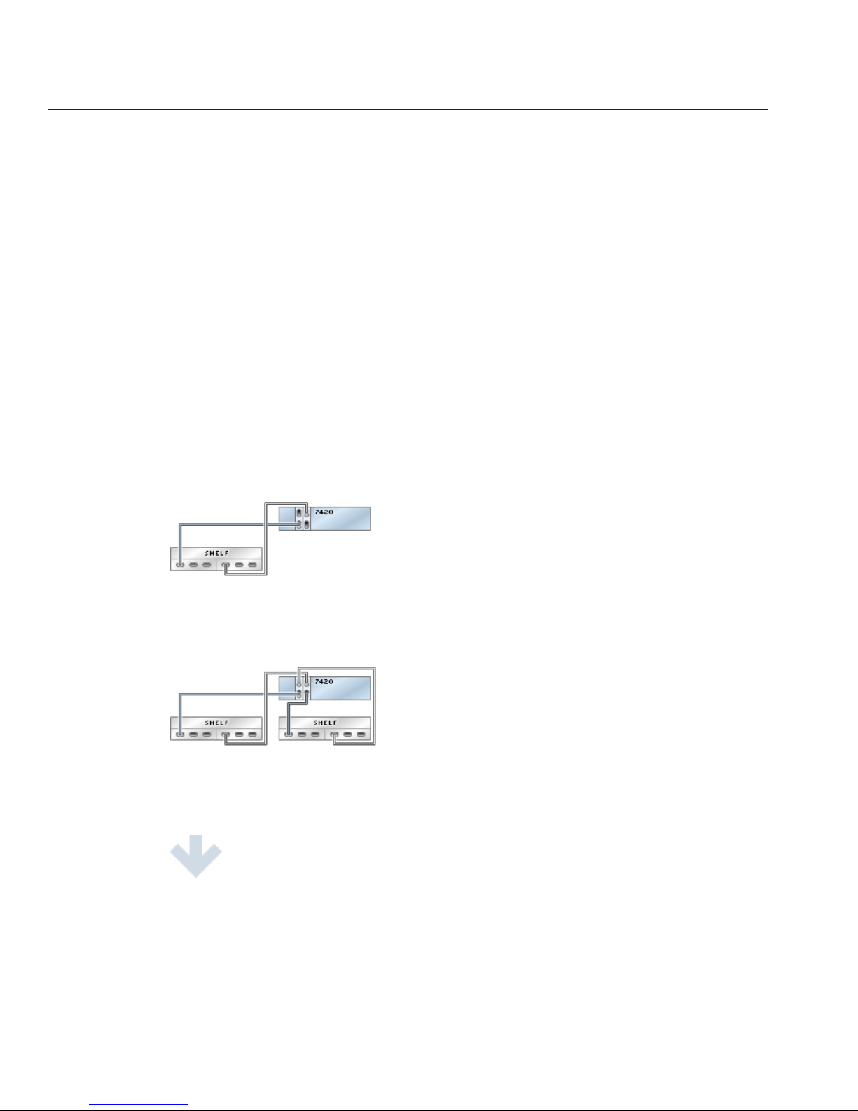
Connecting Sun Disk Shelves/J4x00s to the Sun ZFS
Storage 7120
The Sun ZFS Storage 7120 can support up to two disk shelves. The gures below show the
complete set of supported congurations, as well as steps to migrate from one state to another.
Note: Location of HBAs in the diagrams below are not representative. Refer to the PCIe
Options of your appliance model's Hardware Maintenance Overview for proper slot allocation.
Cabling Diagrams
fig.1 Sun ZFS Storage 7120 with one disk shelf
7120 Cabling
Sun ZFS Storage 7120, 7320, and7420 Appliance Installation Guide • December2012E38245–0152
Page 53

fig.2 Sun ZFS Storage 7120 with two disk shelves
7120 Cabling
Chapter 3 • Cabling 53
Page 54

7320 Cabling
Connecting Sun Disk Shelves/J4x00s to the Sun ZFS
Storage 7320
The Sun ZFS Storage 7320 can support up to six disk shelves. The gures below show a subset of
supported congurations, as well as steps to migrate from one state to another.
Note: Location of HBAs in the diagrams below are not representative. Refer to the PCIe
Options of your appliance model's Hardware Maintenance Overview for proper slot allocation.
Cabling Diagrams
fig.1 Sun ZFS Storage 7320 with one disk shelf
7320 Cabling
Sun ZFS Storage 7120, 7320, and7420 Appliance Installation Guide • December2012E38245–0154
Page 55

fig.2 Sun ZFS Storage 7320 with two disk shelves
fig.3 Sun ZFS Storage 7320 with six disk shelves
7320 Cabling
Chapter 3 • Cabling 55
Page 56

7320 Cluster Cabling
Connecting Sun Disk Shelves/J4x00s to the Sun ZFS
Storage 7320 Cluster
The Sun ZFS Storage 7320 cluster can support up to six disk shelves. The gures below show a
subset of supported congurations, as well as steps to migrate from one state to another.
Note: Location of HBAs in the diagrams below are not representative. Refer to the PCIe
Options of your appliance model's Hardware Maintenance Overview for proper slot allocation.
Cabling Diagrams
fig.1 Sun ZFS Storage 7320 cluster with one disk shelf
7320 Cluster Cabling
Sun ZFS Storage 7120, 7320, and7420 Appliance Installation Guide • December2012E38245–0156
Page 57

fig.2 Sun ZFS Storage 7320 cluster with two disk shelves
fig.3 Sun ZFS Storage 7320 cluster with six disk shelves
7320 Cluster Cabling
Chapter 3 • Cabling 57
Page 58
7420 Cabling pt.1
Connecting Sun Disk Shelves/J4x00s to the Sun ZFS
Storage 7420 (2 HBAs)
The Sun ZFS Storage 7420 supports from two to six HBA cards, each of which connects to a
chain of up to six disk shelves. The gures below show a subset of stable, balanced
congurations with two HBAs, as well as steps to migrate from one state to another.
Note: Location of HBAs in the diagrams below are not representative. Refer to the PCIe
Options of your appliance model's Hardware Maintenance Overview for proper slot allocation.
Cabling Diagrams
fig.1 Sun ZFS Storage 7420 with two HBAs and one disk shelf
fig.2 Sun ZFS Storage 7420 with two HBAs and two disk shelves
7420 Cabling pt.1
Sun ZFS Storage 7120, 7320, and7420 Appliance Installation Guide • December2012E38245–0158
Page 59

fig.3 Sun ZFS Storage 7420 with two HBAs and four disk shelves
7420 Cabling pt.1
Chapter 3 • Cabling 59
Page 60

fig.4 Sun ZFS Storage 7420 with two HBAs and 12 disk shelves
7420 Cabling pt.2
Connecting Sun Disk Shelves/J4x00s to the Sun ZFS
Storage 7420 (3 HBAs)
The Sun ZFS Storage 7420 supports from two to six HBA cards, each of which connects to a
chain of up to six disk shelves. The gures below show a subset of stable, balanced
congurations with three HBAs, as well as steps to migrate from one state to another.
Note: Location of HBAs in the diagrams below are not representative. Refer to the PCIe
Options of your appliance model's Hardware Maintenance Overview for proper slot allocation.
Cabling Diagrams
fig.1 Sun ZFS Storage 7420 with three HBAs and one disk shelf
7420 Cabling pt.2
Sun ZFS Storage 7120, 7320, and7420 Appliance Installation Guide • December2012E38245–0160
Page 61

fig.2 Sun ZFS Storage 7420 with three HBAs and two disk shelves
fig.3 Sun ZFS Storage 7420 with three HBAs and three disk shelves
7420 Cabling pt.2
Chapter 3 • Cabling 61
Page 62

fig.4 Sun ZFS Storage 7420 with three HBAs and six disk shelves
fig.5 Sun ZFS Storage 7420 with three HBAs and 18 disk shelves
7420 Cabling pt.3
Connecting Sun Disk Shelves/J4x00s to the Sun ZFS
Storage 7420 (4 HBAs)
The Sun ZFS Storage 7420 supports from two to six HBA cards, each of which connects to a
chain of up to six disk shelves. The gures below show a subset of stable, balanced
congurations with four HBAs, as well as steps to migrate from one state to another.
Note: Location of HBAs in the diagrams below are not representative. Refer to the PCIe
Options of your appliance model's Hardware Maintenance Overview for proper slot allocation.
7420 Cabling pt.3
Sun ZFS Storage 7120, 7320, and7420 Appliance Installation Guide • December2012E38245–0162
Page 63

Cabling Diagrams
fig.1 Sun ZFS Storage 7420 with four HBAs and one disk shelf
fig.2 Sun ZFS Storage 7420 with four HBAs and two disk shelves
fig.3 Sun ZFS Storage 7420 with four HBAs and three disk shelves
fig.4 Sun ZFS Storage 7420 with four HBAs and four disk shelves
7420 Cabling pt.3
Chapter 3 • Cabling 63
Page 64

fig.5 Sun ZFS Storage 7420 with four HBAs and eight disk shelves
7420 Cabling pt.3
Sun ZFS Storage 7120, 7320, and7420 Appliance Installation Guide • December2012E38245–0164
Page 65

fig.6 Sun ZFS Storage 7420 with four HBAs and 24 disk shelves
7420 Cabling pt.4
Connecting Sun Disk Shelves/J4x00s to the Sun ZFS
Storage 7420 (5 HBAs)
The Sun ZFS Storage 7420 supports from two to six HBA cards, each of which connects to a
chain of up to six disk shelves. The gures below show a subset of stable, balanced
congurations with ve HBAs, as well as steps to migrate from one state to another.
Note: Location of HBAs in the diagrams below are not representative. Refer to the PCIe
Options of your appliance model's Hardware Maintenance Overview for proper slot allocation.
Cabling Diagrams
fig.1 Sun ZFS Storage 7420 with ve HBAs and one disk shelf
7420 Cabling pt.4
Chapter 3 • Cabling 65
Page 66

fig.2 Sun ZFS Storage 7420 with ve HBAs and two disk shelves
fig.3 Sun ZFS Storage 7420 with ve HBAs and three disk shelves
fig.4 Sun ZFS Storage 7420 with ve HBAs and four disk shelves
fig.5 Sun ZFS Storage 7420 with ve HBAs and ve disk shelves
7420 Cabling pt.4
Sun ZFS Storage 7120, 7320, and7420 Appliance Installation Guide • December2012E38245–0166
Page 67

fig.6 Sun ZFS Storage 7420 with ve HBAs and 10 disk shelves
7420 Cabling pt.4
Chapter 3 • Cabling 67
Page 68

fig.7 Sun ZFS Storage 7420 with ve HBAs and 30 disk shelves
7420 Cabling pt.5
Connecting Sun Disk Shelves/J4x00s to the Sun ZFS
Storage 7420 (6 HBAs)
The Sun ZFS Storage 7420 supports from two to six HBA cards, each of which connects to a
chain of up to six disk shelves. The gures below show a subset of stable, balanced
congurations with six HBAs, as well as steps to migrate from one state to another.
Note: Location of HBAs in the diagrams below are not representative. Refer to the PCIe
Options of your appliance model's Hardware Maintenance Overview for proper slot allocation.
Cabling Diagrams
fig.1 Sun ZFS Storage 7420 with six HBAs and one disk shelf
7420 Cabling pt.5
Sun ZFS Storage 7120, 7320, and7420 Appliance Installation Guide • December2012E38245–0168
Page 69

fig.2 Sun ZFS Storage 7420 with six HBAs and two disk shelves
fig.3 Sun ZFS Storage 7420 with six HBAs and three disk shelves
fig.4 Sun ZFS Storage 7420 with six HBAs and four disk shelves
fig.5 Sun ZFS Storage 7420 with six HBAs and ve disk shelves
fig.6 Sun ZFS Storage 7420 with six HBAs and six disk shelves
7420 Cabling pt.5
Chapter 3 • Cabling 69
Page 70

fig.7 Sun ZFS Storage 7420 with six HBAs and 12 disk shelves
7420 Cabling pt.5
Sun ZFS Storage 7120, 7320, and7420 Appliance Installation Guide • December2012E38245–0170
Page 71

fig.8 Sun ZFS Storage 7420 with six HBAs and 36 disk shelves
7420 Cluster Cabling pt.1
Connecting Sun Disk Shelves/J4x00s to the Sun ZFS
Storage 7420 Cluster (2 HBAs)
The Sun ZFS Storage 7420 cluster supports from two to six HBA cards, each of which connects
to a chain of up to six disk shelves. The gures below show a subset of stable, balanced and
redundant cluster congurations with two HBAs, as well as steps to migrate from one state to
another.
Note: Location of HBAs in the diagrams below are not representative. Refer to the PCIe
Options of your appliance model's Hardware Maintenance Overview for proper slot allocation.
Cabling Diagrams
fig.1 Sun ZFS Storage 7420 cluster with two HBAs and one disk shelf
7420 Cluster Cabling pt.1
Chapter 3 • Cabling 71
Page 72

fig.2 Sun ZFS Storage 7420 cluster with two HBAs and two disk shelves
7420 Cluster Cabling pt.1
Sun ZFS Storage 7120, 7320, and7420 Appliance Installation Guide • December2012E38245–0172
Page 73

fig.3 Sun ZFS Storage 7420 cluster with two HBAs and four disk shelves
fig.4 Sun ZFS Storage 7420 cluster with two HBAs and 12 disk shelves
7420 Cluster Cabling pt.1
Chapter 3 • Cabling 73
Page 74

7420 Cluster Cabling pt.2
Connecting Sun Disk Shelves/J4x00s to the Sun ZFS
Storage 7420 Cluster (3 HBAs)
The Sun ZFS Storage 7420 cluster supports from two to six HBA cards, each of which connects
to a chain of up to six disk shelves. The gures below show a subset of stable, balanced and
redundant cluster congurations with three HBAs, as well as steps to migrate from one state to
another.
Note: Location of HBAs in the diagrams below are not representative. Refer to the PCIe
Options of your appliance model's Hardware Maintenance Overview for proper slot allocation.
Cabling Diagrams
fig.1 Sun ZFS Storage 7420 cluster with three HBAs and one disk shelf
fig.2 Sun ZFS Storage 7420 cluster with three HBAs and two disk shelves
7420 Cluster Cabling pt.2
Sun ZFS Storage 7120, 7320, and7420 Appliance Installation Guide • December2012E38245–0174
Page 75

fig.3 Sun ZFS Storage 7420 cluster with three HBAs and three disk shelves
7420 Cluster Cabling pt.2
Chapter 3 • Cabling 75
Page 76

fig.4 Sun ZFS Storage 7420 cluster with three HBAs and six disk shelves
fig.5 Sun ZFS Storage 7420 cluster with three HBAs and 18 disk shelves
7420 Cluster Cabling pt.2
Sun ZFS Storage 7120, 7320, and7420 Appliance Installation Guide • December2012E38245–0176
Page 77

7420 Cluster Cabling pt.3
Connecting Sun Disk Shelves/J4x00s to the Sun ZFS
Storage 7420 Cluster (4 HBAs)
The Sun ZFS Storage 7420 cluster supports from two to six HBA cards, each of which connects
to a chain of up to six disk shelves. The gures below show a subset of stable, balanced and
redundant cluster congurations with four HBAs, as well as steps to migrate from one state to
another.
Note: Location of HBAs in the diagrams below are not representative. Refer to the PCIe
Options of your appliance model's Hardware Maintenance Overview for proper slot allocation.
Cabling Diagrams
fig.1 Sun ZFS Storage 7420 cluster with four HBAs and one disk shelf
fig.2 Sun ZFS Storage 7420 cluster with four HBAs and two disk shelves
7420 Cluster Cabling pt.3
Chapter 3 • Cabling 77
Page 78

fig.3 Sun ZFS Storage 7420 cluster with four HBAs and three disk shelves
fig.4 Sun ZFS Storage 7420 cluster with four HBAs and four disk shelves
7420 Cluster Cabling pt.3
Sun ZFS Storage 7120, 7320, and7420 Appliance Installation Guide • December2012E38245–0178
Page 79

fig.5 Sun ZFS Storage 7420 cluster with four HBAs and eight disk shelves
7420 Cluster Cabling pt.3
Chapter 3 • Cabling 79
Page 80

fig.6 Sun ZFS Storage 7420 cluster with four HBAs and 24 disk shelves
7420 Cluster Cabling pt.4
Connecting Sun Disk Shelves/J4x00s to the Sun ZFS
Storage 7420 Cluster (5 HBAs)
The Sun ZFS Storage 7420 cluster supports from two to six HBA cards, each of which connects
to a chain of up to six disk shelves. The gures below show a subset of stable, balanced and
redundant cluster congurations with ve HBAs, as well as steps to migrate from one state to
another.
Note: Location of HBAs in the diagrams below are not representative. Refer to the PCIe
Options of your appliance model's Hardware Maintenance Overview for proper slot allocation.
Cabling Diagrams
fig.1 Sun ZFS Storage 7420 cluster with ve HBAs and one disk shelf
fig.2 Sun ZFS Storage 7420 cluster with ve HBAs and two disk shelves
7420 Cluster Cabling pt.4
Sun ZFS Storage 7120, 7320, and7420 Appliance Installation Guide • December2012E38245–0180
Page 81

fig.3 Sun ZFS Storage 7420 cluster with ve HBAs and three disk shelves
fig.4 Sun ZFS Storage 7420 cluster with ve HBAs and four disk shelves
fig.5 Sun ZFS Storage 7420 cluster with ve HBAs and ve disk shelves
7420 Cluster Cabling pt.4
Chapter 3 • Cabling 81
Page 82

fig.6 Sun ZFS Storage 7420 cluster with ve HBAs and 10 disk shelves
7420 Cluster Cabling pt.4
Sun ZFS Storage 7120, 7320, and7420 Appliance Installation Guide • December2012E38245–0182
Page 83

fig.7 Sun ZFS Storage 7420 cluster with ve HBAs and 30 disk shelves
7420 Cluster Cabling pt.5
Connecting Sun Disk Shelves/J4x00s to the Sun ZFS
Storage 7420 Cluster (6 HBAs)
The Sun ZFS Storage 7420 cluster supports from two to six HBA cards, each of which connects
to a chain of up to six disk shelves. The gures below show a subset of stable, balanced and
redundant cluster congurations with six HBAs, as well as steps to migrate from one state to
another.
Note: Location of HBAs in the diagrams below are not representative. Refer to the PCIe
Options of your appliance model's Hardware Maintenance Overview for proper slot allocation.
Cabling Diagrams
7420 Cluster Cabling pt.5
Chapter 3 • Cabling 83
Page 84

fig.1 Sun ZFS Storage 7420 cluster with six HBAs and one disk shelf
fig.2 Sun ZFS Storage 7420 cluster with six HBAs and two disk shelves
fig.3 Sun ZFS Storage 7420 cluster with six HBAs and three disk shelves
7420 Cluster Cabling pt.5
Sun ZFS Storage 7120, 7320, and7420 Appliance Installation Guide • December2012E38245–0184
Page 85
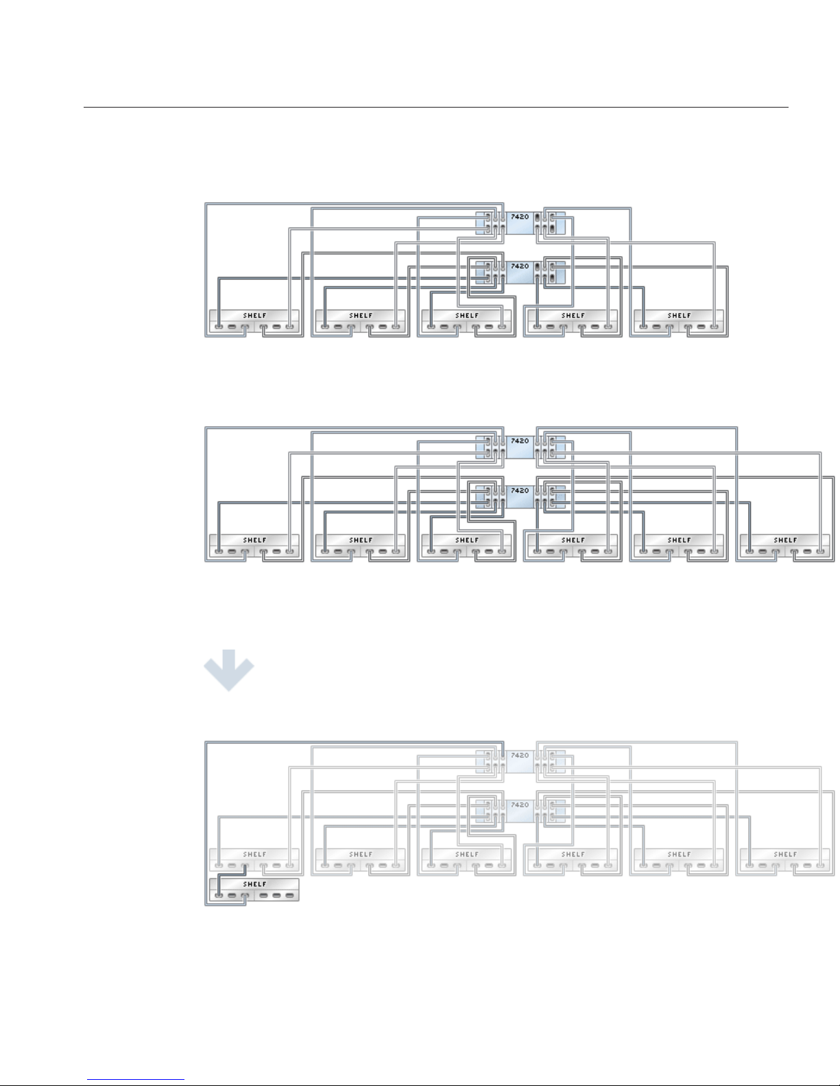
fig.4 Sun ZFS Storage 7420 cluster with six HBAs and four disk shelves
fig.5 Sun ZFS Storage 7420 cluster with six HBAs and ve disk shelves
fig.6 Sun ZFS Storage 7420 cluster with six HBAs and six disk shelves
7420 Cluster Cabling pt.5
Chapter 3 • Cabling 85
Page 86
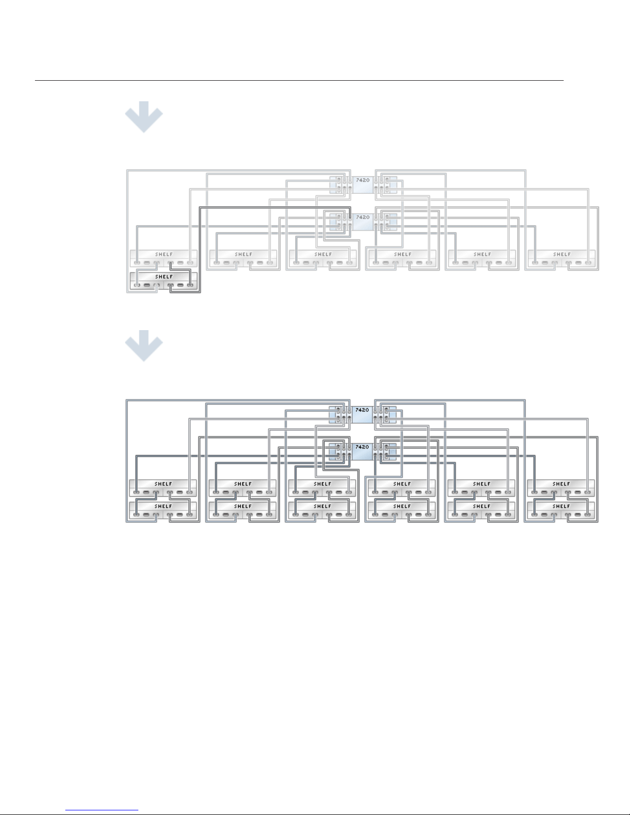
fig.7 Sun ZFS Storage 7420 cluster with six HBAs and 12 disk shelves
7420 Cluster Cabling pt.5
Sun ZFS Storage 7120, 7320, and7420 Appliance Installation Guide • December2012E38245–0186
Page 87

fig.8 Sun ZFS Storage 7420 cluster with six HBAs and 36 disk shelves
DE2-24
Connecting DE2 Enclosures to the Sun ZFS Storage
7120
The Sun ZFS Storage 7120 can support up to two DE2-24 drive enclosures. The gures below
show the complete set of supported congurations, as well as steps to migrate from one state to
another.
Note: Location of HBAs in the diagrams below are not representative. Refer to the PCIe
Options of your appliance model's Hardware Maintenance Overview for proper slot allocation.
Cabling Diagrams
fig.1 Sun ZFS Storage 7120 with one drive enclosure
DE2-24
Chapter 3 • Cabling 87
Page 88

fig.2 Sun ZFS Storage 7120 with two drive enclosures
DE2-24
Sun ZFS Storage 7120, 7320, and7420 Appliance Installation Guide • December2012E38245–0188
Page 89

DE2-24
Connecting DE2 Enclosures to the Sun ZFS Storage
7320
The Sun ZFS Storage 7320 can support up to six DE2-24 drive enclosures. The gures below
show a subset of supported congurations, as well as steps to migrate from one state to another.
Note: Location of HBAs in the diagrams below are not representative. Refer to the PCIe
Options of your appliance model's Hardware Maintenance Overview for proper slot allocation.
Cabling Diagrams
fig.1 Sun ZFS Storage 7320 with one drive enclosure
DE2-24
Chapter 3 • Cabling 89
Page 90
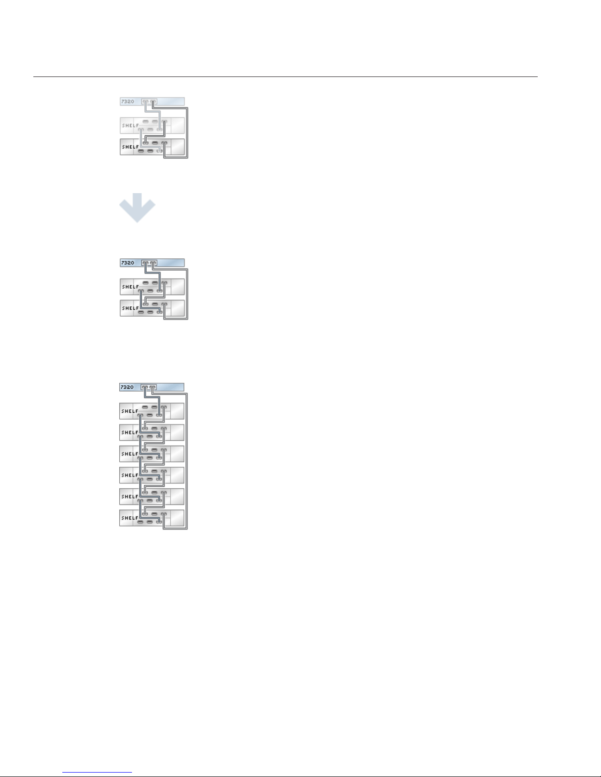
fig.2 Sun ZFS Storage 7320 with two drive enclosures
fig.3 Sun ZFS Storage 7320 with six drive enclosures
DE2-24
Sun ZFS Storage 7120, 7320, and7420 Appliance Installation Guide • December2012E38245–0190
Page 91

DE2-24
Connecting DE2 Enclosures to the Sun ZFS Storage
7320 Cluster
The Sun ZFS Storage 7320 cluster can support up to six DE2-24 drive enclosures. The gures
below show a subset of supported congurations, as well as steps to migrate from one state to
another.
Note: Location of HBAs in the diagrams below are not representative. Refer to the PCIe
Options of your appliance model's Hardware Maintenance Overview for proper slot allocation.
Cabling Diagrams
fig.1 Sun ZFS Storage 7320 cluster with one drive enclosure
DE2-24
Chapter 3 • Cabling 91
Page 92

fig.2 Sun ZFS Storage 7320 cluster with two drive enclosures
fig.3 Sun ZFS Storage 7320 cluster with six drive enclosures
DE2-24
Sun ZFS Storage 7120, 7320, and7420 Appliance Installation Guide • December2012E38245–0192
Page 93

DE2-24x2
Connecting DE2 Enclosures to the Sun ZFS Storage
7420 (2 HBAs)
The Sun ZFS Storage 7420 supports from two to six HBA cards, each of which connects to a
chain of up to six DE2-24 drive enclosures. The gures below show a subset of stable, balanced
congurations with two HBAs, as well as steps to migrate from one state to another.
Note: Location of HBAs in the diagrams below are not representative. Refer to the PCIe
Options of your appliance model's Hardware Maintenance Overview for proper slot allocation.
Cabling Diagrams
fig.1 Sun ZFS Storage 7420 with two HBAs and one drive enclosure
fig.2 Sun ZFS Storage 7420 with two HBAs and two drive enclosures
DE2-24x2
Chapter 3 • Cabling 93
Page 94
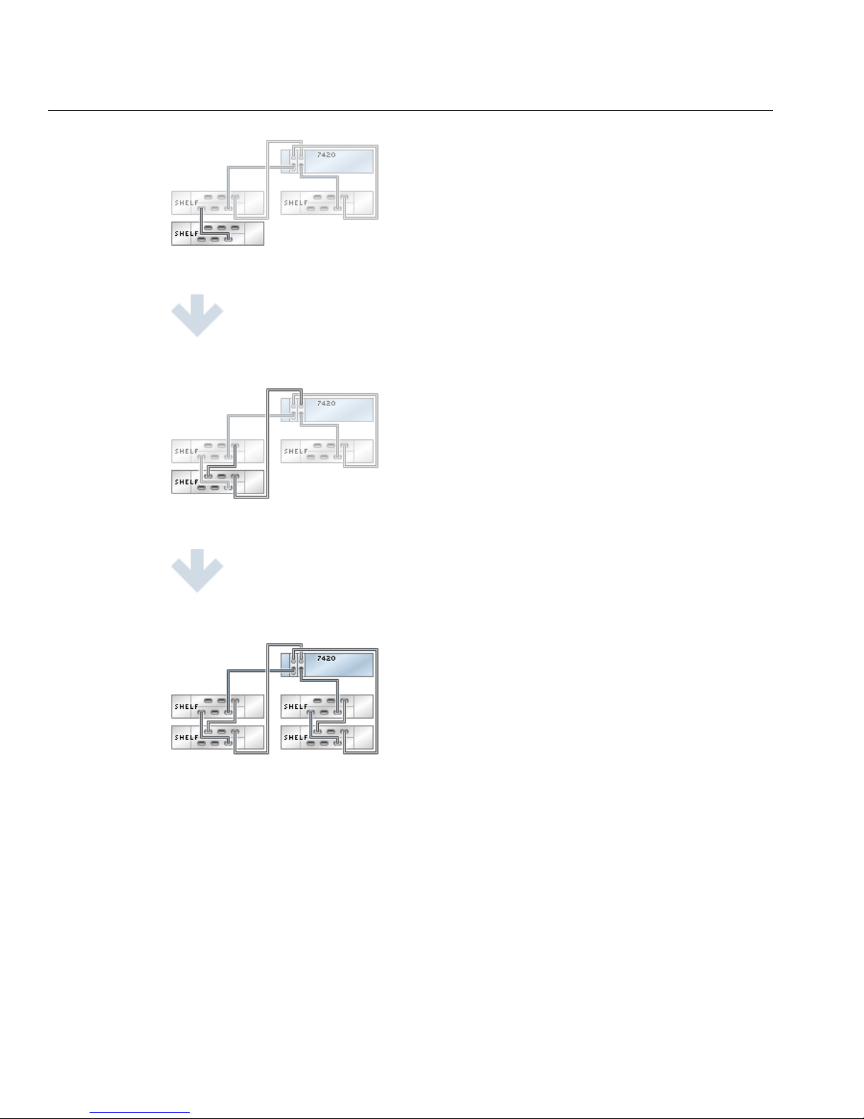
fig.3 Sun ZFS Storage 7420 with two HBAs and four drive enclosures
DE2-24x2
Sun ZFS Storage 7120, 7320, and7420 Appliance Installation Guide • December2012E38245–0194
Page 95
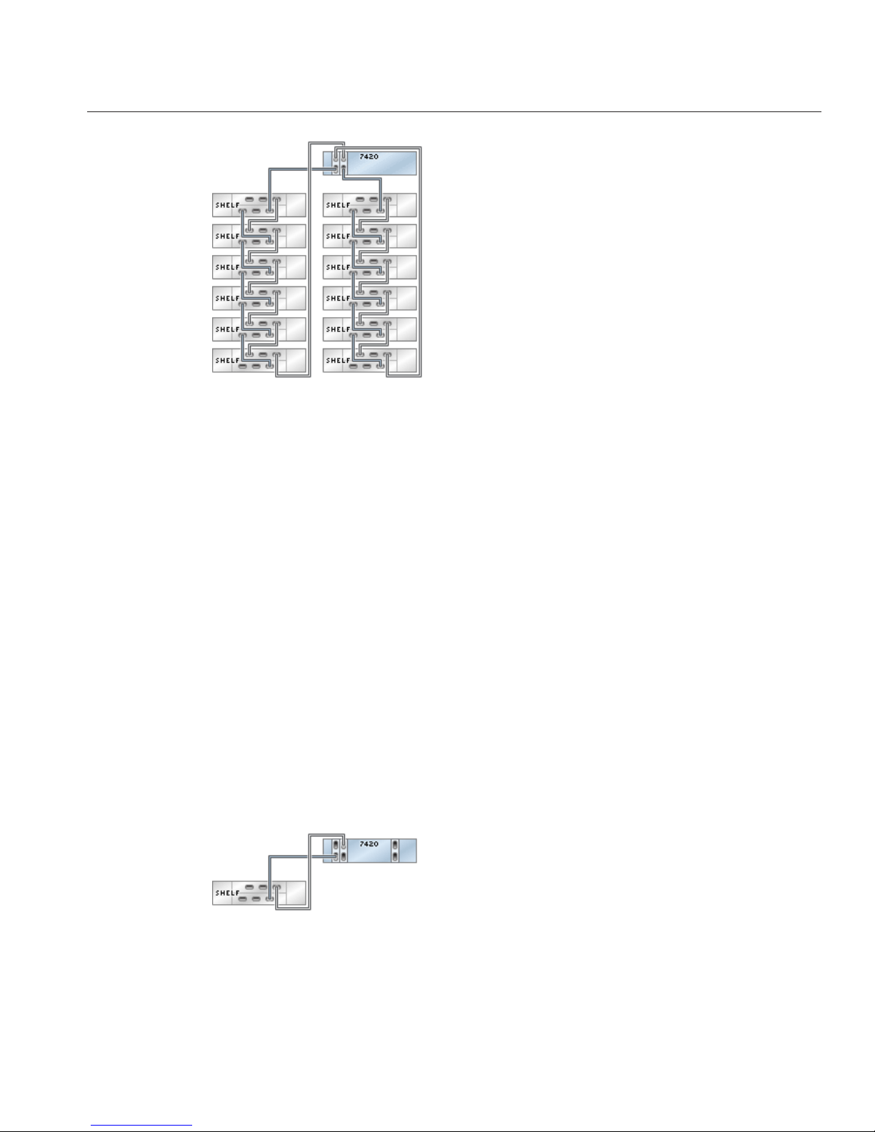
fig.4 Sun ZFS Storage 7420 with two HBAs and 12 drive enclosures
DE2-24x3
Connecting DE2 Enclosures to the Sun ZFS Storage
7420 (3 HBAs)
The Sun ZFS Storage 7420 supports from two to six HBA cards, each of which connects to a
chain of up to six DE2-24 drive enclosures. The gures below show a subset of stable, balanced
congurations with three HBAs, as well as steps to migrate from one state to another.
Note: Location of HBAs in the diagrams below are not representative. Refer to the PCIe
Options of your appliance model's Hardware Maintenance Overview for proper slot allocation.
Cabling Diagrams
fig.1 Sun ZFS Storage 7420 with three HBAs and one drive enclosure
DE2-24x3
Chapter 3 • Cabling 95
Page 96

fig.2 Sun ZFS Storage 7420 with three HBAs and two drive enclosures
fig.3 Sun ZFS Storage 7420 with three HBAs and three drive enclosures
DE2-24x3
Sun ZFS Storage 7120, 7320, and7420 Appliance Installation Guide • December2012E38245–0196
Page 97

fig.4 Sun ZFS Storage 7420 with three HBAs and six drive enclosures
fig.5 Sun ZFS Storage 7420 with three HBAs and 18 drive enclosures
DE2-24x4
Connecting DE2 Enclosures to the Sun ZFS Storage
7420 (4 HBAs)
The Sun ZFS Storage 7420 supports from two to six HBA cards, each of which connects to a
chain of up to six DE2-24 drive enclosures. The gures below show a subset of stable, balanced
congurations with four HBAs, as well as steps to migrate from one state to another.
Note: Location of HBAs in the diagrams below are not representative. Refer to the PCIe
Options of your appliance model's Hardware Maintenance Overview for proper slot allocation.
DE2-24x4
Chapter 3 • Cabling 97
Page 98

Cabling Diagrams
fig.1 Sun ZFS Storage 7420 with four HBAs and one drive enclosure
fig.2 Sun ZFS Storage 7420 with four HBAs and two drive enclosures
fig.3 Sun ZFS Storage 7420 with four HBAs and three drive enclosures
fig.4 Sun ZFS Storage 7420 with four HBAs and four drive enclosures
DE2-24x4
Sun ZFS Storage 7120, 7320, and7420 Appliance Installation Guide • December2012E38245–0198
Page 99

fig.5 Sun ZFS Storage 7420 with four HBAs and eight drive enclosures
DE2-24x4
Chapter 3 • Cabling 99
Page 100

fig.6 Sun ZFS Storage 7420 with four HBAs and 24 drive enclosures
DE2-24x5
Connecting DE2 Enclosures to the Sun ZFS Storage
7420 (5 HBAs)
The Sun ZFS Storage 7420 supports from two to six HBA cards, each of which connects to a
chain of up to six DE2-24 drive enclosures. The gures below show a subset of stable, balanced
congurations with ve HBAs, as well as steps to migrate from one state to another.
Note: Location of HBAs in the diagrams below are not representative. Refer to the PCIe
Options of your appliance model's Hardware Maintenance Overview for proper slot allocation.
Cabling Diagrams
fig.1 Sun ZFS Storage 7420 with ve HBAs and one drive enclosure
DE2-24x5
Sun ZFS Storage 7120, 7320, and7420 Appliance Installation Guide • December2012E38245–01100
 Loading...