

Page 1

Sun™XVR-200
Graphics Accelerator
Installation Guide
Sun Microsystems, Inc.
www.sun.com
Part No. 819-5737-11
December 2006, Revision A
Submit comments about this document at: http://www.sun.com/hwdocs/feedback
Page 2

Copyright ©2006 SunMicrosystems, Inc., 4150 Network Circle, Santa Clara, California 95054, U.S.A. All rights reserved.
U.S. GovernmentRights -Commercial software. Government users are subject to the Sun Microsystems, Inc.standard license agreement and
applicable provisions ofthe FAR and its supplements. Use is subject to license terms.
This distributionmay includematerials developedby third parties.
Parts ofthe product maybe derivedfrom Berkeley BSD systems, licensed from the University of California. UNIX is a registered trademarkin
the U.S.and inother countries,exclusively licensedthrough X/Open Company, Ltd.
Sun, SunMicrosystems, Solaris, Sun Fire, SunVTS and the Sun logo are trademarks or registered trademarksof SunMicrosystems, Inc. in the
U.S. andother countries.
OpenGL isa registered trademark of Silicon Graphics, Inc.
The OPENLOOK andSun
TM
Graphical UserInterface wasdeveloped bySun Microsystems, Inc.for itsusers andlicensees. Sunacknowledges
the pioneeringefforts of Xerox in researchingand developingthe conceptof visualor graphicaluser interfacesfor thecomputer industry. Sun
holds anon-exclusive licensefrom Xerox to the Xerox Graphical User Interface, which license also covers Sun’s licensees who implement OPEN
LOOK GUIsand otherwisecomply withSun’s writtenlicense agreements.
This product iscovered and controlled by U.S. Export Control laws and may be subject to the export or import laws in other countries. Nuclear,
missile, chemicalbiological weaponsor nuclearmaritime enduses orend users,whether direct orindirect, are strictly prohibited. Export or
reexport to countries subject to U.S. embargo or to entities identified on U.S. export exclusion lists, including, but not limited to, the denied
persons andspecially designatednationals listsis strictlyprohibited.
Copyright © 2006 Sun Microsystems, Inc., 4150 Network Circle, Santa Clara, California 95054, Etats-Unis. Tous droits réservés.
L’utilisation est soumise aux termes de la Licence.
Cette distribution peut comprendre des composants développés par des tierces parties.
Des parties de ce produit pourront être dérivées des systèmes Berkeley BSD licenciés par l’Université de Californie. UNIX est une marque
déposée aux Etats-Unis et dans d’autres pays et licenciée exclusivement par X/Open Company, Ltd.
Sun, Sun Microsystems, Solaris, Sun Fire, SunVTS et le logo Sun sont des marques de fabrique ou des marques déposées de Sun Microsystems,
Inc. aux Etats-Unis et dans d’autres pays.
OpenGL est une marque déposée de Silicon Graphics, Inc.
TM
L’interface d’utilisation graphique OPEN LOOK et Sun
a été développée par Sun Microsystems, Inc. pour ses utilisateurs et licenciés. Sun
reconnaît les efforts de pionniers de Xerox pour la recherche et le développement du concept des interfaces d’utilisation visuelle ou graphique
pour l’industrie de l’informatique. Sun détient une license non exclusive de Xerox sur l’interface d’utilisation graphique Xerox, cette licence
couvrant également les licenciés de Sun qui mettent en place l’interface d’utilisation graphique OPEN LOOK et qui, en outre, se conforment
aux licences écrites de Sun.
Ce produit est soumis à la législation américaine en matière de contrôle des exportations et peut être soumis à la règlementation en vigueur
dans d’autres pays dans le domaine des exportations et importations. Les utilisations, ou utilisateurs finaux, pour des armes nucléaires,des
missiles, des armes biologiques et chimiques ou du nucléaire maritime, directement ou indirectement, sont strictement interdites. Les
exportations ou réexportations vers les pays sous embargo américain, ou vers des entités figurant sur les listes d’exclusion d’exportation
américaines, y compris, mais de manière non exhaustive, la liste de personnes qui font objet d’un ordre de ne pas participer, d’une façon directe
ou indirecte, aux exportations des produits ou des services qui sont régis par la législation américaine en matière de contrôle des exportations
et la liste de ressortissants spécifiquement désignés, sont rigoureusement interdites.
Please
Recycle
Page 3

Regulatory Compliance Statements
The Sun XVR-200 graphics accelerator is supported on the Sun Fire T2000 server as a Class A device according to worldwide
requirements for EMI (Electromagnetic Interference.) The following statements apply:
FCC Class A Notice
This device complies with Part 15 of the FCC Rules. Operation is subject to the following two conditions:
1. This device may not cause harmful interference.
2. This device must accept any interference received, including interference that may cause undesired operation.
Note: This equipment has been tested and found to comply with the limits for a Class A digital device, pursuant to Part 15 of
the FCC Rules. These limits are designed to provide reasonable protection against harmful interference when the equipment
is operated in a commercial environment. This equipment generates, uses, and can radiate radio frequency energy, and if it is
not installed and used in accordance with the instruction manual, it may cause harmful interference to radio communications.
Operation of this equipment in a residential area is likely to cause harmful interference, in which case the user will be required
to correct the interference at his own expense.
Shielded Cables: Connections between the workstation and peripherals must be made using shielded cables to comply with
FCC radio frequency emission limits. Networking connections can be made using unshielded twisted-pair (UTP) cables.
Modifications: Any modifications made to this device that are not approved bySun Microsystems, Inc. may void the authority
granted to the user by the FCC to operate this equipment.
ICES-003 Class A Notice - Avis NMB-003, Classe A
This Class A digital apparatus complies with Canadian ICES-003.
Cet appareil numérique de la classe A est conforme à la norme NMB-003 du Canada.
iii
Page 4

BSMI Class A Notice
The following statement is applicable to products shipped to Taiwan and marked as Class A on the product compliance
label.
iv Sun XVR-200 Graphics Accelerator Installation Guide • December 2006
Page 5

Declaration of Conformity
Compliance Model Number: G55-MDDE32LPDF
Product Family Name: Sun XVR-200 Graphics Accelerator (X3777)
EMC
USA—FCC Class A
This equipment complies with Part 15 of the FCC Rules. Operation is subject to the following two conditions:
1. This equipment may not cause harmful interference.
2. This equipment must accept any interference that may cause undesired operation.
European Union
This equipment complies with the following requirements of the EMC Directive 89/336/EEC:
As Telecommunication Network Equipment (TNE) in Both Telecom Centers and Other Than Telecom Centers per (as applicable):
EN 300 386 V.1.3.2 (2003-05) Required Limits:
EN 55022:1994 +A1:1995 +A2:1997 ClassA
EN 61000-3-2:2000 Pass
EN 61000-3-3:1995 +A1:2000 Pass
IEC 61000-4-2 6 kV (Direct), 8 kV (Air)
IEC 61000-4-3 3 V/m 80-1000MHz, 10 V/m 800-960 MHz, and 1400-2000 MHz
IEC 61000-4-4 1 kV AC and DC Power Lines, 0.5 kV Signal Lines
IEC 61000-4-5 2 kV AC Line-Gnd, 1 kV AC Line-Line and Outdoor Signal Lines, 0.5 kV Indoor signal Lines > 10m.
IEC 61000-4-6 3 V
IEC 61000-4-11 Pass
As Information Technology Equipment (ITE) Class A per (as applicable):
EN 55022:1994 +A1:1995 +A2:1997 Class A
EN 61000-3-2:2000 Pass
EN 61000-3-3:1995 +A1:2000 Pass
EN 55024:1998 +A1:2001 +A2:2003 Required Limits:
IEC 61000-4-2 4 kV (Direct), 8 kV (Air)
IEC 61000-4-3 3 V/m
IEC 61000-4-4 1 kV AC Power Lines, 0.5 kV Signal and DC Power Lines
IEC 61000-4-5 1 kV AC Line-Line and Outdoor Signal Lines, 2 kV AC Line-Gnd, 0.5 kV DC Power Lines
IEC 61000-4-6 3 V
IEC 61000-4-8 1 A/m
IEC 61000-4-11 Pass
Safety: This equipment complies with the following requirements of the Low Voltage Directive 73/23/EEC:
EC Type Examination Certificates:
EN 60950-1:2001, 1st Edition
IEC 60950-1:2001, 1st Edition
Evaluated to all CB Countries
UL and cUL/CSA 60950-1:2001, CSA C22.2 No. 60950-00
FDA DHHS Accession Number (Monitors Only)
Declaration of Conformity v
Page 6

Supplementary Information: This product was tested and complies with all the requirements for the CE Mark. This
equipment complies with the Restriction of Hazardous Substances (roHS) directive 2002/95/EC.
/S/ /S/
Dennis P. Symanski DATE
Worldwide, Compliance Engineering
Sun Microsystems, Inc.
4150 Network Circle, MPK15-102
Santa Clara, CA 95054 U.S.A.
Tel: 650-786-3255
Fax: 650-786-3723
Donald Cameron DATE
Program Manager/Customer Quality
Sun Microsystems Scotland, Limited
Blackness Road, Phase I, Main Bldg.
Springfield, EH49 7LR
Scotland, United Kingdom
Tel: +44 1 506 672 539 Fax: +44 1 506 670 011
vi Sun XVR-200 Graphics Accelerator Installation Guide • December 2006
Page 7

Contents
Preface xiii
1. Sun XVR-200 Graphics Accelerator Overview 1
Installation Kit 1
Features 2
PCI-Express Bus Interface 3
8+24 Simultaneous Visuals 3
Cached Pixmaps 3
OpenGL Support 4
2. Installing the Software and Hardware 5
Before Installation 5
Software Requirements 5
Installing the Software 6
Software Package Locations 6
Installing the Sun XVR-200 Software 7
Removing the Software 10
Installing the Hardware 11
Man Pages 12
Changing Resolution and Color Depth Through the GUI 13
vii
Page 8

Interactive Configuration 14
Noninteractive Configuration 15
Dual-Screen Mode 17
3. Modifying the Xservers File 19
Configuring the Graphics Device Through the Xservers File 19
A. Changing the Console Resolution at the OpenBoot Prompt 21
Overview 21
Output-Device Method 23
Video-Mode Method 24
Video-Timing Method 26
Video Mode Troubleshooting 27
B. Monitor Cable Adapters 29
Cable Adapter 29
Connecting Monitors With DVI Video Ports 30
Monitors With HD15 (VGA) Video Ports 31
C. Sun XVR-200 Graphics Accelerator Specifications 33
Board Specifications 33
LFH60 Connector Pinout 34
DVI Connector Pinouts 36
HD15 (VGA) Connector Pinouts 38
D. SunVTS 39
E. Keyboard and Mouse 41
Index 43
viii Sun XVR-200 Graphics Accelerator Installation Guide • December 2006
Page 9

Figures
FIGURE 1-1 Sun XVR-200 Graphics Accelerator 2
FIGURE 1-2 Sun XVR-200 Graphics Accelerator Back Panel LFH-60 Port 3
FIGURE 2-1 Configuration Interface Display 14
FIGURE B-1 LHF60 Video Port Connection to DVI Video Ports Using LFH60 – 2xDVI Adapter Splitter
Cable 30
FIGURE B-2 LHF60 Video Port Connection Using DVI–HD15 Adapters 31
FIGURE C-1 LFH60 Connector and Pin Signal Descriptions 35
FIGURE C-2 DVI Connector Pinouts 36
FIGURE C-3 HD15 (VGA) Connector Pinouts 38
ix
Page 10

x Sun XVR-200 Graphics Accelerator Installation Guide • December 2006
Page 11

Tables
TABLE 2-1 Sun XVR-200 Graphics Accelerator CD Directories 6
TABLE 2-2 Location of Sun XVR-200 Software Packages 6
TABLE 2-3 Solaris Package Names 7
TABLE 2-4 Supported Systems 11
TABLE 2-5 Configuration Interface Options 15
TABLE 2-6 Parameter Options 15
TABLE A-1 Default Console Resolution 21
TABLE A-2 Screen Resolutions by Video Mode 24
TABLE A-3 Video Mode Troubleshooting 27
TABLE C-1 Sun XVR-200 Graphics Accelerator Power Consumption 33
TABLE C-2 Sun XVR-200 Graphics Accelerator DVI Cable Pinouts 36
TABLE C-3 Sun XVR-200 Graphics Accelerator HD15 Connector Pinouts 38
xi
Page 12

xii Sun XVR-200 Graphics Accelerator Installation Guide • December 2006
Page 13

Preface
This guide describes how to install the SunTMXVR-200 graphics accelerator software
and hardware in a Sun Fire
How This Document Is Organized
Chapter 1 provides an overview of the Sun XVR-200 graphics accelerator.
Chapter 2 provides hardware and software installation instructions.
Chapter 3 describes the procedure for modifying your Xservers file for identifying
the graphics device.
Appendix A describes how to change the console screen resolution.
Appendix B provides information on cabling for digital and analog monitors.
TM
T2000 system.
Appendix C provides the Sun XVR-200 graphics accelerator product specifications.
Appendix D provides information regarding SunVTS
Appendix E provides keyboard and mouse information.
TM
.
xiii
Page 14

Using UNIX Commands
This document might not contain information about basic UNIX®commands and
procedures such as shutting down the system, booting the system, and configuring
devices. Refer to the following for this information:
■ Software documentation that you received with your system
■ Solaris™ Operating System documentation, which is at:
http://docs.sun.com
Shell Prompts
Shell Prompt
C shell machine-name%
C shell superuser machine-name#
Bourne shell and Korn shell $
Bourne shell and Korn shell superuser #
xiv Sun XVR-200 Graphics Accelerator Installation Guide • December 2006
Page 15

Typographic Conventions
Typeface
AaBbCc123 The names of commands, files,
AaBbCc123 What you type, when contrasted
AaBbCc123 Book titles, new words or terms,
1 The settings on your browser might differ from these settings.
1
Meaning Examples
Edit your.login file.
and directories; on-screen
computer output
with on-screen computer output
words to be emphasized.
Replace command-line variables
with real names or values.
Use ls -a to list all files.
% You have mail.
su
%
Password:
Read Chapter 6 in the User’s Guide.
These are called class options.
You must be superuser to do this.
To delete a file, type rm filename.
Documentation, Support, and Training
Sun Function URL
Documentation http://www.sun.com/documentation/
Support http://www.sun.com/support/
Training http://www.sun.com/training/
Third-Party Web Sites
Sun is not responsible for the availability of third-party web sites mentioned in this
document. Sun does not endorse and is not responsible or liable for any content,
advertising, products, or other materials that are available on or through such sites
or resources. Sun will not be responsible or liable for any actual or alleged damage
or loss caused by or in connection with the use of or reliance on any such content,
goods, or services that are available on or through such sites or resources.
Preface xv
Page 16

Sun Welcomes Your Comments
Sun is interested in improving its documentation and welcomes your comments and
suggestions. You can submit your comments by going to:
http://www.sun.com/hwdocs/feedback
Please include the title and part number of your document with your feedback:
Sun XVR-200 Graphics Accelerator Installation Guide , part number 819-5737-10
xvi Sun XVR-200 Graphics Accelerator Installation Guide • December 2006
Page 17

CHAPTER
1
Sun XVR-200 Graphics Accelerator
Overview
The Sun XVR-200 graphics accelerator (FIGURE 1-1) is a low-profile single-slot 24-bit
PCI-Express graphics frame buffer. The Sun XVR-200 graphics accelerator runs on
the Sun Fire T2000 system. This chapter includes the following topics:
■ “Installation Kit” on page 1
■ “Features” on page 2
Installation Kit
The Sun XVR-200 graphics accelerator installation kit includes:
■ Sun XVR-200 graphics accelerator
■ Sun XVR-200 software CD-ROM
■ LFH-60 – 2xDVI-I adapter splitter cable
■ Two DVI – HD15 adapters
■ Antistatic wrist strap
■ Sun XVR-200 Graphics Accelerator Installation Guide, this document
1
Page 18

Features
The Sun XVR-200 graphics accelerator (FIGURE 1-1) offers the following advanced
features:
■ 32-Mbyte PCI-Express (PCI-E) x1 bus interface
■ 8+24-bit simultaneous visuals
■ Off-screen pixmap caching
■ Sun OpenGL
extension
See the following sections for details.
Sun XVR-200
graphics accelerator
®
for SolarisTMsupport through Sun Direct Pixel Access (DPA)
Backplate
FIGURE 1-1 Sun XVR-200 Graphics Accelerator
2 Sun XVR-200 Graphics Accelerator Installation Guide • December 2006
Page 19
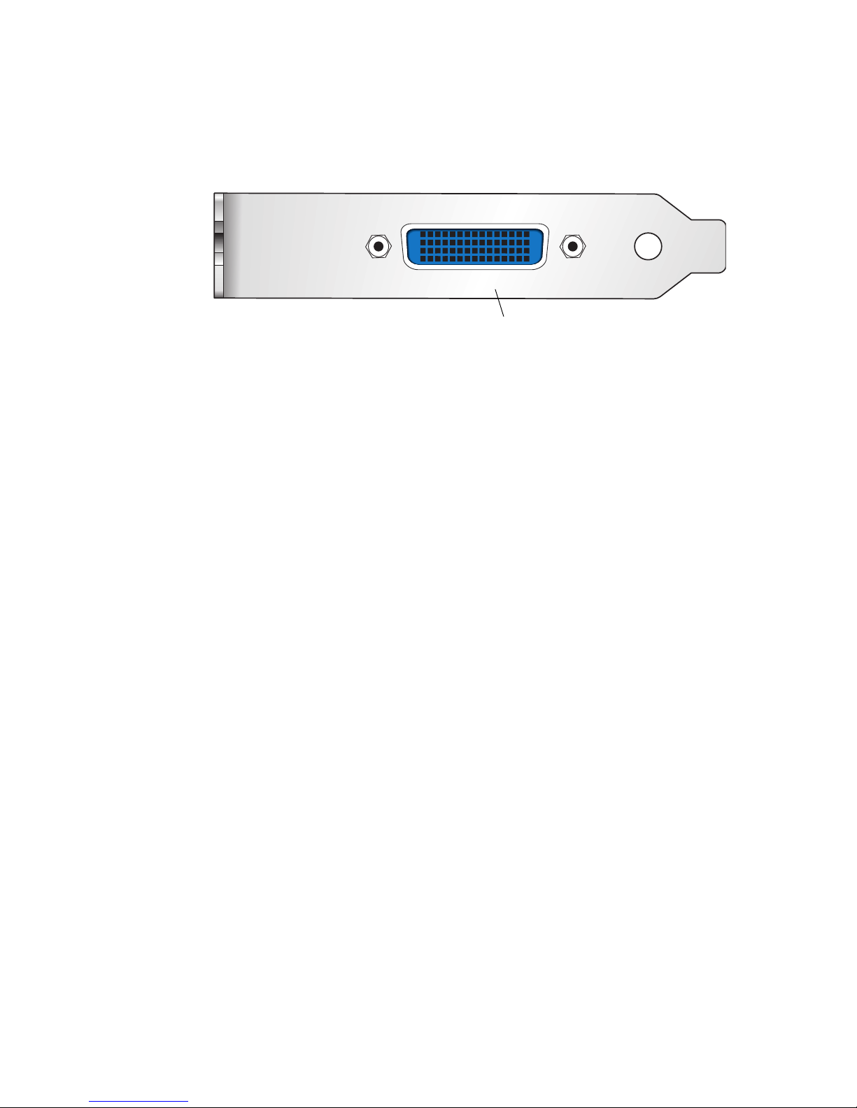
FIGURE 1-2 shows the Sun XVR-200 graphics accelerator back panel LFH-60 I/O port.
LFH-60 video port
FIGURE 1-2 Sun XVR-200 Graphics Accelerator Back Panel LFH-60 Port
PCI-Express Bus Interface
The Sun XVR-200 graphics accelerator is a low-profile single-slot 32-Mbyte frame
buffer keyed for an x1 PCI-Express bus interface. The output connector is an LFH-60
video port that requires the monitor cable adapters provided in the installation kit
for DVI and HD15 (VGA) type monitor cabling.
8+24 Simultaneous Visuals
The 8+24 mode simultaneously supports 8- and 24-bit visuals. This mode addresses
the classic colormap flashing issue with a 24-bit visual while providing the 8-bit
visual that is required by some legacy 8-bit color only applications.
Cached Pixmaps
All Sun XVR-200 graphics accelerators support off-screen pixmap caching. Cached
pixmaps are those that are stored in the off-screen memory. These off-screen
pixmaps allow faster transfer rates to and from on-screen windows.
The available off-screen memory depends on the amount of video memory, the
current resolution, and depth settings. For example, the Sun XVR-200 graphics
accelerator has 32 Mbytes of video memory.
If the board is running at 1024 × 768 resolution with a depth of 8-bits, 768K is used
for on-screen memory. That leaves 31.2 Mbytes available for pixmaps. In 24-bit and
8+24-bit modes, the on-screen memory that is used is four times larger than what is
used in the 8-bit mode.
Chapter 1 Sun XVR-200 Graphics Accelerator Overview 3
Page 20

The largest pixmaps are stored in off-screen memory. If a larger pixmap replaces a
smaller pixmap in the off-screen memory, the smaller pixmap moves to system
memory and remains there even after the larger pixmap is destroyed.
OpenGL Support
Sun OpenGL for Solaris support is provided through the Direct Pixel Access (DPA)
Extension. The Sun OpenGL 1.5 for Solaris software support is provided in the
Solaris 10 1/06 Operating System.
4 Sun XVR-200 Graphics Accelerator Installation Guide • December 2006
Page 21

CHAPTER
2
Installing the Software and
Hardware
This chapter provides Sun XVR-200 graphics accelerator software and hardware
installation information.
■ “Before Installation” on page 5
■ “Software Requirements” on page 5
■ “Installing the Software” on page 6
■ “Removing the Software” on page 10
■ “Installing the Hardware” on page 11
■ “Man Pages” on page 12
■ “Changing Resolution and Color Depth Through the GUI” on page 13
Before Installation
Refer to the Solaris Handbook for Sun Peripherals that corresponds to your Solaris
Operating System. The handbook describes how to shut down the system safely
before installing any internal cards and how to reboot your system after installation.
Software Requirements
The Solaris 10 1/06 Operating System, or subsequent compatible version of the
Solaris Operating System, is required on your SPARC
Sun XVR-200 graphics accelerator software.
®
system before installing the
5
Page 22

Installing the Software
Install the Sun XVR-200 software from the CD-ROM provided with your Sun
XVR-200 graphics accelerator installation kit.
graphics accelerator CD-ROM directories.
TABLE 2-1 Sun XVR-200 Graphics Accelerator CD Directories
Directory Name Description
Copyright U.S. version of copyright
Docs Sun XVR-200 graphics accelerator documentation
FR_Copyright French version of copyright
README Listing of Sun XVR-200 graphics accelerator CD contents
SLA_TRANSLATED.pdf Translated software licensing agreement
Solaris_10/ Sun XVR-200 software packages
Sun_XVR-200_Driver_SLAandEntitlement.txt Software licensing agreement and information
install Product installation script
uninstall Product removal script
TABLE 2-1 lists the Sun XVR-200
Software Package Locations
The Sun XVR-200 software packages are located in the directory listed in TABLE 2-2.
TABLE 2-2 Location of Sun XVR-200 Software Packages
Software Packages Directory Location
Solaris 10 software /cdrom/cdrom0/sun_xvr_200/Solaris_10/Packages
6 Sun XVR-200 Graphics Accelerator Installation Guide • December 2006
Page 23

Software Package Names
TABLE 2-3 lists the Sun XVR-200 software package names and descriptions.
TABLE 2-3 Solaris Package Names
Package name Description
TSImkox 64-bit system software and device driver
TSImkow Window system support
TSImkomn Manual pages
Installing the Sun XVR-200 Software
If necessary, see Appendix E for keyboard and mouse installation references.
1. Boot your system at the ok prompt.
ok boot
Boot your system to the ok prompt by using the procedures outlined in your server
installation guide. If you have not already set up your server, you need to use the
integrated service console with the server. After you have been able to successfully
boot the server and log in as superuser, go to Step 2.
2. As superuser, check if the Sun XVR-200 graphics accelerator is already on your
system.
To do this, type:
# /usr/bin/pkginfo | grep mko
3. Insert the Sun XVR-200 graphics accelerator CD-ROM into the drive.
■ If the drive is already mounted, type the following, and go to Step 4:
# cd /cdrom/cdrom0
■ If the CD-ROM is not already mounted, type:
# mount -F hsfs -O -o ro /dev/dsk/c0t6d0s0 /cdrom
# cd /cdrom
Chapter 2 Installing the Software and Hardware 7
Page 24

Note – The CD-ROM device might be different on your system. For example,
/dev/dsk/c0t2d0s2.
4. Run the installation script. Type:
# ./install
The following Sun Entitlement information is displayed:
Sun Microsystems, Inc. (“Sun”) ENTITLEMENT for SOFTWARE
Licensee/Company: Entity receiving Software
Effective Date: Date Sun delivers the Software to You.
Software: “Software” means all software provided to You to be used with
the Host.
Host: The hardware product described in the Software’s documentation
with which the Software is intended to be used.
.
.
.
Do you accept the license agreement? [y/n]: y
At the end of the licensing agreement information, you are asked to accept it.
8 Sun XVR-200 Graphics Accelerator Installation Guide • December 2006
Page 25

5. Type y, and Return, to accept the license agreement.
The following is displayed:
Installing TSImkox.v TSImkomn TSImkow for Solaris 10 ...
*** Installation of drivers is complete.
To uninstall this software, use the ’uninstall’ script on this CDROM, or
the following script:
/var/tmp/xvr-200.uninstall
A log of this installation can be found at:
/var/tmp/xvr-200.install.2006.03.29
To configure a Sun XVR-200 accelerator, use the fbconfig
utility. See the fbconfig(1m) and TSCmko_config(1m) manual
pages for more details.
*** IMPORTANT NOTE! ***
This system must be rebooted for the new software to take effect.
6. Install the Sun XVR-200 graphics accelerator.
(See “Installing the Hardware” on page 11.)
7. Do a reconfiguration reboot of your system at the ok prompt to complete the
installation:
ok boot -r
To use the Sun XVR-200 graphics accelerator as a console, type a Solaris prompt:
# eeprom output-device=screen
# eeprom input-device=keyboard
Chapter 2 Installing the Software and Hardware 9
Page 26

Removing the Software
1. Log in as superuser.
2. Insert the Sun XVR-200 graphics accelerator CD-ROM into the drive.
■ If the drive is already mounted, type the following, and go to Step 3:
# cd /cdrom/cdrom0
■ If the CD-ROM is not already mounted, type:
# mount -F hsfs -O -o ro /dev/dsk/c0t6d0s0 /cdrom
# cd /cdrom
Note – The CD-ROM device might be different on your system. For example,
/dev/dsk/c0t2d0s2.
3. To remove Sun XVR-200 graphics accelerator software, type:
./uninstall
#
In this example, the following is displayed.
Removal of Sun XVR-200 Sun XVR-200 Graphics accelerator Software is complete.
A log of this uninstall is at:
/var/tmp/xvr-200.uninstall.2006.03.29
10 Sun XVR-200 Graphics Accelerator Installation Guide • December 2006
Page 27

Installing the Hardware
Refer to the hardware installation documentation provided with your Sun system
for instructions on accessing your system and installing Sun PCI-Express (PCI-E)
graphics cards. Your system platform documentation also provides removal
procedures.
To find the most recent information on supported systems for the Sun XVR-200
graphics accelerator, and additional specifications, go to:
http://www.sun.com/desktop/products/graphics/xvr200/
TABLE 2-4 lists the supported systems and number of PCI-E slots supported.
TABLE 2-4 Supported Systems
System Maximum Number of Boards
Sun Fire T2000 system 1
Chapter 2 Installing the Software and Hardware 11
Page 28

Man Pages
The Sun XVR-200 graphics accelerator man pages describe how you can query and
set frame buffer attributes such as screen resolutions and visual configurations.
Use the fbconfig(1M) man page for configuring all Sun graphics accelerators.
TSImko_config(1M) contains Sun XVR-200 device-specific configuration
information.
● To get a list of all graphics devices on your system, type:
host% fbconfig -list
This example shows a list of graphics devices displayed:
Device-Filename Specific Config Program
--------------- ---------------------- /dev/fbs/mko0 TSImko_config
Use the fbconfig -help option to display the attributes and parameters
information of the man page.
host% fbconfig -dev mko0 -help
● To access the fbconfig man page, type:
host% man fbconfig
● To access the Sun XVR-200 graphics accelerator man page, type:
host% man TSImko_config
12 Sun XVR-200 Graphics Accelerator Installation Guide • December 2006
Page 29

Changing Resolution and Color Depth
Through the GUI
The default resolution is dictated either by EDID information from the connected
monitor or by the console resolution that is set (Appendix A). In the absence of this
piece of information, the default resolution is 1024 × 768 × 75 Hz and the default
window system color depth is 24-bit.
● To get a list of available screen resolutions for your display device, type:
host% fbconfig -res \?
See Appendix A, “Changing the Console Resolution”, which includes methods on
changing your screen resolution from the OpenBoot ok prompt, a list of supported
resolutions, and additional information.
However, if you decide to set a different resolution and color depth configuration
under the X Window System, follow the instructions in this section to set your
resolution and color depth appropriately.
You can use the fbconfig utility any time after installation to change these
parameters and to turn on dual-screen mode.
Please see the man page on TSImko_config for a detailed description.
Note – dual-screen mode is a feature described in “Dual-Screen Mode” on page 17.
In this mode, you can only configure the Sun XVR-200 to a color depth of 24-bits.
The next two sections describe two methods of using fbconfig to configure the
graphics board.
Chapter 2 Installing the Software and Hardware 13
Page 30
Interactive Configuration
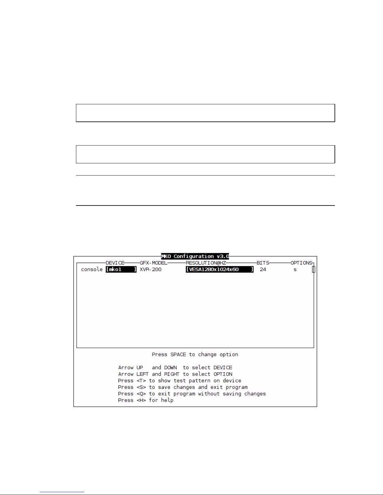
fbconfig has an interactive menu-style interface (FIGURE 2-1).
● To configure your Sun XVR-200 graphics accelerator, type one of the following:
# fbconfig -i
or
# fbconfig -dev mko0 -i
Note – If the X Window System is running on the Sun XVR-200 graphics accelerator
to be configured, please exit out of it before running fbconfig. Failure to do so
could result in a corrupted screen for the remainder of the X Windows session.
The Sun XVR-200 graphics accelerator device is listed in the left column of the
configuration screen displayed by fbconfig -i (
FIGURE 2-1).
FIGURE 2-1 Configuration Interface Display
14 Sun XVR-200 Graphics Accelerator Installation Guide • December 2006
Page 31

TABLE 2-4 lists the configuration interface options:
TABLE 2-5 Configuration Interface Options
Option Description
Up/Down Arrow To select the desired graphics device you want to modify.
Left/Right Arrow To select the parameter to modify (for example, resolution,
color depth, or sync).
Space Bar To modify the parameter for the selected graphics device
(displays a menu when applicable).
t Puts a test pattern on the entire display (press any key to
return to the main screen). Note that the test pattern feature
is disabled if the X Window System is running.
s Saves current settings and exits.
h Help
q
Exits the program without saving any changes.
Note – To enable dual-screen, select the OPTION menu and enter w. (See “Dual-
Screen Mode” on page 17.)
Noninteractive Configuration
Sometimes it is convenient to configure the Sun XVR-200 graphics accelerator
noninteractively. This method is especially useful when configuring many systems
identically or when the appropriate configuration for the system is already known.
You can set the parameters using the interactive version by specifying the option
followed by a desired value.
TABLE 2-6 Parameter Options
Parameter Description
TABLE 2-4 lists the parameters.
-d device Selects the device to configure.
-res resolution Sets the resolution.
-res \? Lists supported resolutions.
Chapter 2 Installing the Software and Hardware 15
Page 32

TABLE 2-6 Parameter Options (Continued)
Parameter Description
-file machine | system Specifies whether to modify OWconfig from
/etc/openwin/server/etc or
/usr/openwin/server/etc, respectively.
-depth 8|24|8+24 Changes the color depth to 8 only or 8+24 mode.
-defaults Changes all option values to their default values.
doublewide,
doublehigh enable/disable
-24only enable/disable Forces all windows to use 24-bit visuals. This disables 8+24
-cachedpixmap enable/disable Turns off the off-screen cached pixmap feature. Default is
-propt Displays current settings.
-prconf Displays hardware information.
-help Shows complete usage listing.
Enable/disable the dual-screen output feature. (See “Dual-
Screen Mode” on page 17.)
mode and might prohibit some 8-bit applications from working.
enable.
Note – By default, the color depth is set to 24-bit for all resolutions.
Examples
To configure the resolution to 1280 × 1024 × 60 Hz, type:
# fbconfig -res 1280x1024x60
Note – If no device is specified, fbconfig configures the console Sun XVR-200
graphics accelerator.
To verify the resolution prior to setting it permanently, add the word try after the
resolution name. This option displays a test pattern on the screen until you press the
Return key. The resolution is then accepted or rejected. For example:
# fbconfig
16 Sun XVR-200 Graphics Accelerator Installation Guide • December 2006
-dev /dev/fbs/mko0 -res 1280x1024x60 try
Page 33

To set the resolution to 1024 × 768 × 60 with a single TrueColor visual (no 8-bit
PseudoColor visual):
# fbconfig -res 1024x768x60 -24only enable
To display the current settings for /dev/fbs/mko0:
# fbconfig -dev /dev/fbs/mko0 -propt
Dual-Screen Mode
The Sun XVR-200 graphics accelerator has the ability to support two displays – two
digital displays, two analog displays, or one analog and one digital. You can
configure the card so that the two displays appear as one unified screen to the X
Windows display. In other words, windows can be easily moved between the two
displays (without the need for a special xinerama mode). This unified screen mode
is also called dual-screen mode.
The Sun XVR-200 graphics accelerator has only one graphic processor and two
DACs. The drawing engine is capable of driving both DACs. See “X Window System
(Dual-Screen Mode) Configuration” below.
Console Display Configuration
In console mode (that is, prior to starting the X Window System), only one monitor
head is used.
X Window System (Dual-Screen Mode) Configuration
You can configure graphics boards under the X Window System in either a singlescreen mode or a dual-screen mode, using the fbconfig utility.
● To configure the graphics board to dual-screen mode, type:
# /usr/sbin/fbconfig -dev /dev/fbs/mko0 -doublewide enable
When running fbconfig in the interactive mode (fbconfig -i), select w under the
OPTION menu to enable dual-screen mode.
Chapter 2 Installing the Software and Hardware 17
Page 34

In dual-head configurations, the X Window System acts as one single display across
two screens. Both heads must be set to the same resolution, and each is limited to
1600 × 1200 × 60 analog. So, the maximum effective resolution across both screens is
3200 × 1200 × 60 analog. In the dual-screen mode, only the 24-bit TrueColor visual is
supported.
In single-head configurations, the resolution is limited to 1920 × 1200 × 76, and
supports 8-bit, 24-bit, and 8+24-bit modes.
Note – These limits apply to analog output only. Digital output is restricted to
1280 × 1024 × 60. Dual-head configurations that include a digital monitor are also
limited to 1280 × 1024 × 60 for both heads.
18 Sun XVR-200 Graphics Accelerator Installation Guide • December 2006
Page 35

CHAPTER
3
Modifying the Xservers File
To configure the Sun XVR-200 graphics accelerator, you must modify your
Xservers file. This chapter describes how to make that modification.
Configuring the Graphics Device
Through the Xservers File
The Sun XVR-200 graphics accelerator device name is mko0. To configure the
Xservers file, do the following:
1. Become superuser and open the /etc/dt/config/Xservers file.
# cd /etc/dt/config
# vi + Xservers
If the /etc/dt/config/Xservers file does not exist, create the /etc/dt/config
directory and copy the Xservers file from /usr/dt/config/Xservers to
/etc/dt/config.
# mkdir -p /etc/dt/config
#
cp /usr/dt/config/Xservers /etc/dt/config
# cd /etc/dt/config
# vi + Xservers
19
Page 36

2. Modify the file by adding the device location for the Sun XVR-200 graphics
accelerator device.
Enter the Xservers file content in one long line.
This example shows the Xservers configuration file modified for one Sun XVR-200
graphics accelerator (mko0) to start the desktop:
:0 Local local_uid@console root /usr/openwin/bin/Xserver :0 -dev
/dev/fbs/mko0 -nobanner
3. Log out, then log back in.
4. If you are editing the Xservers file after completing installation, reboot your
system.
20 Sun XVR-200 Graphics Accelerator Installation Guide • December 2006
Page 37

APPENDIX
A
Changing the Console Resolution at
the OpenBoot Prompt
This appendix describes how to change the console screen resolution.
■ “Overview” on page 21
■ “Output-Device Method” on page 23
■ “Video-Mode Method” on page 24
■ “Video-Timing Method” on page 26
■ “Video Mode Troubleshooting” on page 27
Overview
Changing the screen resolution at the OpenBoot ok prompt enables you to view
console boot messages and the DT login screen. If a type of monitor is used where
the EDID auto-detect is not preset at the ok prompt, console boot messages and
DT login screen will not display. In this case, set screen resolutions using fbconfig
or the GUI method, which displays console boot messages and the DT login screen
(see “Changing Resolution and Color Depth Through the GUI” on page 13).
Console Resolution
The the Sun XVR-200 graphics accelerator has a default console resolution and
default color depth as shown in the
TABLE A-1 Default Console Resolution
Board Resolution Refresh Bits/Pixels Sync
XVR-200 Auto Detect - 24 Separate/composite
TABLE A-1:
21
Page 38

Reason for Changing the Console Resolution
Normally, the default console resolution is sufficient for most users. If the monitor
does not sync up at the default console resolution, it might be necessary to choose a
different console resolution.
Guidelines for Changing the Console Resolution
By default, all console resolutions are set to 24-bit mode. Use fbconfig -i to test a
resolution before configuring the console to that resolution.
Note – Digital output on the LFH-60 port is limited to 1280 × 1024 × 60.
EDID Auto-Detect Feature
Auto-Detect is limited to 1280 × 1024 × 60 on the digital video port only. If overrides
are used to exceed this limit, only analog signals will be produced by the DVI port.
Digital signals will be turned off.
If you are using a monitor with DDC2B/EDID protocol the default resolution will be
determined using the Auto-Detect feature. With this protocol, the Sun XVR-200
graphics accelerator first checks the Established Timing Identifiers (taking the first
one supported) then tries to match the Standard Timings.
Note – The monitor must be powered up and turned on prior to booting the system
in order for the Sun XVR-200 graphics accelerator to communicate with it. Some
adapters and cables might block this signal.
If the Auto-Detect feature fails, the card will default to 1024 × 768 × 75 Hz.
Note – The other methods described in this appendix override any information
obtained through EDID.
22 Sun XVR-200 Graphics Accelerator Installation Guide • December 2006
Page 39

Output-Device Method
To specify the console resolution of Sun XVR-200 graphics accelerator through the
output-device environment variable, use the format screen:rAxBxC where:
■ A is the desired horizontal resolution.
■ B is the desired vertical resolution.
■ C is the desired refresh rate.
The system checks these values against an internal list of resolutions (see “Video-
Mode Method” on page 24 for a list of video modes) and use the corresponding
entry as the console resolution. For example, to use VESA1280 × 1024 × 75 as the
console resolution, go to the ok prompt and type:
ok setenv output-device screen:r1024x768x75
ok reset-all
Note – The Sun Fire T2000 system default console defaults to:
output-device=virtual-console
input-device=virtual-console
To use the Sun XVR-200 graphics accelerator as a console, type a Solaris prompt:
# eeprom output-device=screen
# eeprom input-device=keyboard
Or, at the ok prompt, type:
ok setenv output-device screen
ok setenv input-device keyboard
Reboot after installing the Sun XVR-200 graphics accelerator into the Sun Fire T2000
system.
Appendix A Changing the Console Resolution at the OpenBoot Prompt 23
Page 40

Video-Mode Method
You can set the Sun XVR-200 console resolution at the ok prompt in boot PROM
mode, using one of the 32 preinstalled resolution modes. These resolution settings
are identified by video modes 1-32.
● To change the video mode, type:
ok nvedit
0:8 value video-mode
1: <ctrl-c>
ok
nvstore
ok setenv use-nvramrc? true
ok reset-all
where 8 is the selected video mode.
Note – The last three commands enable the NVRAM. Without these lines, the
changes you make with nvedit will be ignored.
TABLE A-2 Screen Resolutions by Video Mode
Video Mode Resolution
1 640 × 480 ×72
2 640 × 480 ×75
3 640 × 480 ×85
4 800 × 600 × 60
5 800 × 600 × 72
6 800 × 600 × 75
7 800 × 600 × 85
8 1024 × 768 × 60
9 1024 × 768 × 70
10 1024 × 768 × 75
11 1024 × 768 × 77 ∗
12 1024 × 768 × 85
13 1024 × 800 × 85 ∗
24 Sun XVR-200 Graphics Accelerator Installation Guide • December 2006
Page 41

TABLE A-2 Screen Resolutions by Video Mode (Continued)
Video Mode Resolution
14 1152 × 900 × 60
15 1152 × 900 × 66 ∗
16 1152 × 900 × 70
17 1152 × 900 × 75
18 1152 × 900 × 76 ∗
19 1152 × 900 × 85
20 1280 × 800 × 76 ∗
21 1280 × 1024 × 60
22 1280 × 1024 × 67
23 1280 × 1024 × 67 ∗
24 1280 × 1024 × 75
25 1280 × 1024 × 76 ∗
26 1280 × 1024 × 85
27 1600 × 1000 × 66 ∗
28 1600 × 1000 × 76 ∗
29 1600 × 1200 × 60
30 1600 × 1200 × 65
31 1600 × 1200 × 70
32 1600 × 1200 × 75
* Uses composite sync.
Appendix A Changing the Console Resolution at the OpenBoot Prompt 25
Page 42

Video-Timing Method
If all of the previously described methods fail for your configuration, it is possible to
specify the exact timing numbers for a particular resolution. The last method for
setting the console resolution also uses nvedit. This method is more involved and
requires knowledge of all timing parameters for the desired resolution, and is only
to be used for monitors with resolutions that are not available in the video-mode
method.
Note – The video-timing method should be used only if the preceding methods
have been unsuccessful.
For example, to set the console resolution to 1280 × 1024 × 76 Hz, type:
ok nvedit
0::video-timing " 1280, 384, 32, 64, 1024, 43, 3, 8, 135000000, 0" ;
1: <ctrl-c>
nvstore
ok
ok setenv use-nvramrc? true
ok reset-all
Note – The syntax is very important. The spaces must be present exactly as they
appear in the example.
Note – The last three commands enable the NVRAM. Without these entry lines, the
changes you make with nvedit will be ignored.
26 Sun XVR-200 Graphics Accelerator Installation Guide • December 2006
Page 43

The following is a brief description of the 10 parameters used in this method:
■ Horizontal resolution (in pixels)
■ Horizontal blanking total
■ Horizontal front porch
■ Horizontal sync width
■ Vertical resolution (in lines)
■ Vertical blanking total
■ Vertical front porch
■ Vertical sync width
■ Dotclock in Hz
■ Sync value:
■ 0 separate sync
■ 25 6sync on green
■ 512 positive vertical sync pulse
■ 1024 positive horizontal sync pulse
■ 2048 composite sync
You can add the sync values together to select more than one of the preceding
values.
Video Mode Troubleshooting
TABLE A-3 Video Mode Troubleshooting
Problem Solution
Used the method
described in this
Appendix to
configure the
console resolution,
but the card still
defaults to
something other
than the resolution
specified.
A priority scheme is used to determine the boot console resolution.
The Sun XVR-200 graphics accelerator firmware checks the various
methods in order of priority. If the device finds the resolution from
the current method, it uses that resolution. Otherwise, it goes down
the priority list to find the resolution information. Finally, if there is
no resolution information, the device uses the default resolution.
The resolution-setting methods are enumerated in order of
decreasing priority:
1. output-device method (see “Output-Device Method” on page 23)
2. video-timing method (see “Video-Timing Method” on page 26)
3. video-mode method (see “Video-Mode Method” on page 24)
4. DDC2B/EDID (see “Output-Device Method” on page 23)
5. Default resolution for the board
Appendix A Changing the Console Resolution at the OpenBoot Prompt 27
Page 44

28 Sun XVR-200 Graphics Accelerator Installation Guide • December 2006
Page 45

APPENDIX
B
Monitor Cable Adapters
This appendix describes Sun XVR-200 graphics accelerator cabling for DVI and
HD15 (VGA) type monitor video ports.
■ “Cable Adapter” on page 29
■ “Connecting Monitors With DVI Video Ports” on page 30
■ “Monitors With HD15 (VGA) Video Ports” on page 31
Cable Adapter
The Sun XVR-200 graphics accelerator installation kit includes the following adapter
assemblies:
■ LFH60 – 2xDVI-I adapter splitter cable
■ Two DVI – HD15 adapters
You can order DVI
(http://store.sun.com).
– HD15 adapters (part number 530-3474) through the Sun store
29
Page 46
Connecting Monitors With DVI Video
Ports
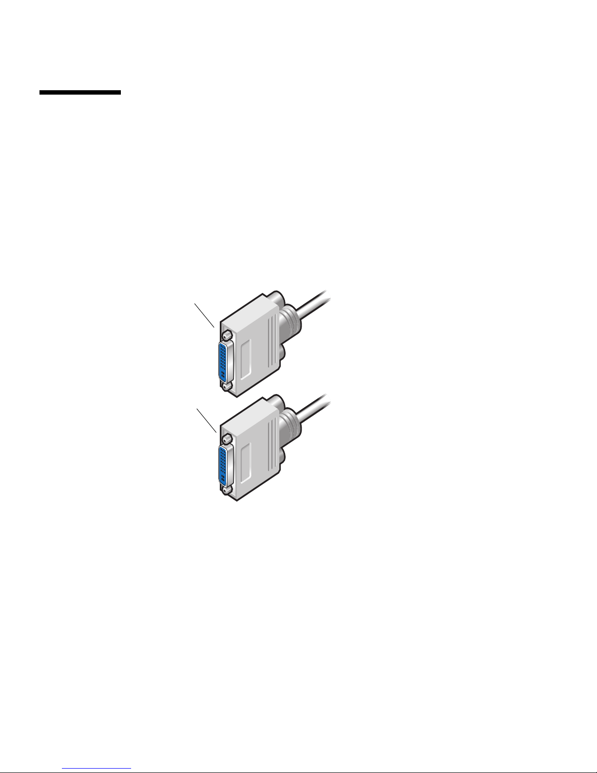
1. Connect the LFH60 end of LFH60–DVI adapter splitter cable to the Sun XVR-200
graphics accelerator LFH60 video port.
2. Connect each DVI connector end of the adapter splitter cable to the DVI ports of
your digital monitor (
DVI cable connector
To DVI video port
DVI cable connector
FIGURE B-1).
To LFH60 video port
(LFH60 – 2xDVI adapter
splitter cable)
To DVI video port
FIGURE B-1 LHF60 Video Port Connection to DVI Video Ports Using LFH60 – 2xDVI
Adapter Splitter Cable
30 Sun XVR-200 Graphics Accelerator Installation Guide • December 2006
Page 47
Monitors With HD15 (VGA) Video Ports
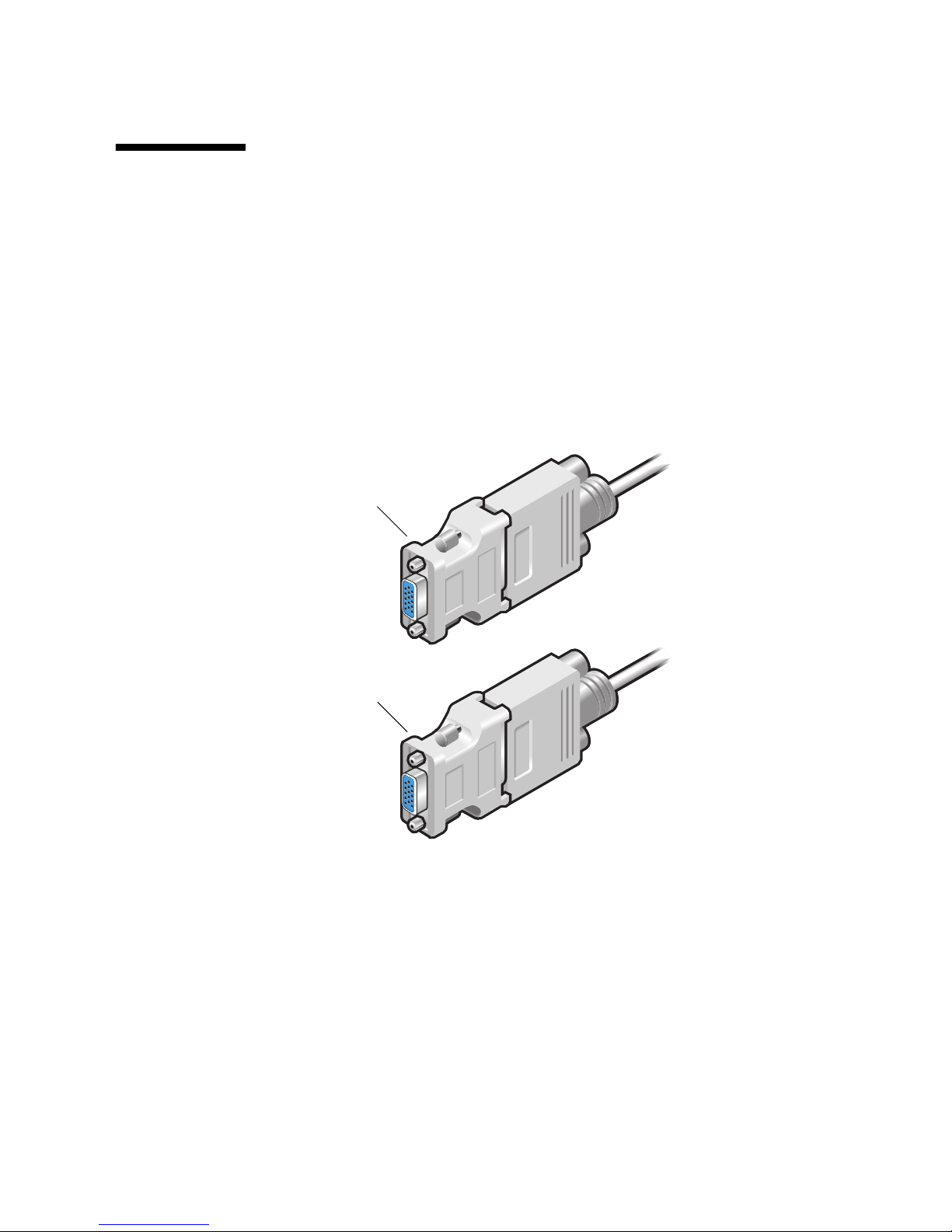
1. Connect the LFH60 end of the LFH60–DVI adapter splitter cable to the Sun
XVR-200 graphics accelerator LFH60 video port.
2. Connect a DVI–HD15 adapter to each end of the LFH60–DVI adapter splitter cable
DVI connector (
3. Connect the HD15 end of the DVI-HD15 adapter to the HD15 (VGA) monitor
video port.
DVI – HD15 adapter
To HD15 (VGA) video port
FIGURE B-2).
To LFH60 video port
(LFH60 – 2xDVI adapter
splitter cable)
DVI – HD15 adapter
To HD15 (VGA) video port
FIGURE B-2 LHF60 Video Port Connection Using DVI–HD15 Adapters
Appendix B Monitor Cable Adapters 31
Page 48

32 Sun XVR-200 Graphics Accelerator Installation Guide • December 2006
Page 49

APPENDIX
C
Sun XVR-200 Graphics Accelerator
Specifications
This appendix provides the Sun XVR-200 graphics accelerator product specifications.
■ “Board Specifications” on page 33
■ “LFH60 Connector Pinout” on page 34
■ “DVI Connector Pinouts” on page 36
■ “HD15 (VGA) Connector Pinouts” on page 38
Board Specifications
This graphics accelerator is for use with UL Listed ITE that have installation
instructions detailing user installation of card cage accessories.
TABLE C-1 lists the product specifications.
TABLE C-1 Sun XVR-200 Graphics Accelerator Power Consumption
Parameter Specification
Frame buffer 32 Mbytes
Hardware cursor 3 color, 64 x 64 bitmap
Color lookup tables 256 entries
PCI-E interface PCIe x 1
Video interface Analog (75 ohm) or DVI
Temperature rating 0° to 55° C operating
-40° to 75° C nonoperating
Humidity rating 20 to 80% operating (noncondensing)
5 to 95% nonoperating (noncondensing
33
Page 50

TABLE C-1 Sun XVR-200 Graphics Accelerator Power Consumption (Continued)
Parameter Specification
Power rating +5V @ 3 Amps
Dimensions 16.13cm x 6.89cm
(6.35" x 2.712")
Dot clock max 360 MHz (primary)
230 MHz (secondary)
135 MHz (digital)
Video sync Separate, composite
Video connector LFH60 (15pm D-shell, VGA or DVI-I using
splitter cable)
Boot support IEEE 1275 Compliant F Code
LFH60 Connector Pinout
FIGURE C-1 shows the Sun XVR-200 LFH60 video connector and pin signal
descriptions
.
34 Sun XVR-200 Graphics Accelerator Installation Guide • December 2006
Page 51

1516 301
4645 3160
Display
#1/#3
Display
#2/#4
FIGURE C-1 LFH60 Connector and Pin Signal Descriptions
Appendix C Sun XVR-200 Graphics Accelerator Specifications 35
Page 52
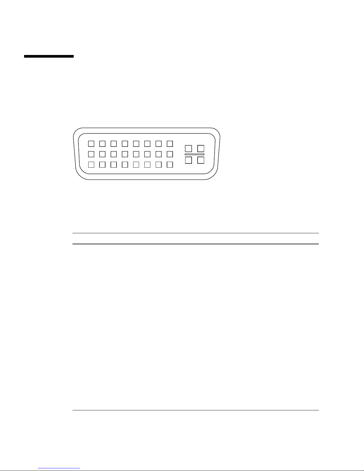
DVI Connector Pinouts
FIGURE C-2 and TABLE C-2 shows the DVI connector and pinout signals. The DVI
cable connector is a 30-pin connector for a supported workstation monitor.
16
24
C1 C2
C5
C3 C4
18
9
17
FIGURE C-2 DVI Connector Pinouts
TABLE C-2 Sun XVR-200 Graphics Accelerator DVI Cable Pinouts
Pin Signal
1 TMDS Data 2-
2 TMDS Data 2+
3 TMDS Data 2/4 Shield
4 TMDS Data 4-
5 TMDS Data 4+
6 DDC Clock
7 DDC Data
8 Analog vertical sync
9 TMDS Data 1-
10 TMDS Data 1+
11 TMDS Data 1/3 shield
12 TMDS Data 3-
13 TMDS Data 3+
14 +5V power
15 Ground
36 Sun XVR-200 Graphics Accelerator Installation Guide • December 2006
Page 53

TABLE C-2 Sun XVR-200 Graphics Accelerator DVI Cable Pinouts (Continued)
Pin Signal
16 Hot plug detect
17 TMDS Data 0-
18 TMDS Data 0+
19 TMDS Data 0/5 shield
20 TMDS Data 5-
21 TMDS Data 5+
22 TMDS Clock shield
23 TMDS Clock+
24 TMDS Clock-
C1 Red analog
C2 Green analog
C3 Blue analog
C4 Analog horizontal sync
C5 Analog ground
Appendix C Sun XVR-200 Graphics Accelerator Specifications 37
Page 54

HD15 (VGA) Connector Pinouts
FIGURE C-3 and TABLE C-3 shows the HD15 (VGA) connector and pinout signals.
51
10
15
FIGURE C-3 HD15 (VGA) Connector Pinouts
TABLE C-3 Sun XVR-200 Graphics Accelerator HD15 Connector Pinouts
Pin Signal
1 Red analog video
2 Green analog video
3 Blue analog video
6
11
4 Monitor ID2
5 Ground
6 Red shield
7 Green shield
8 Blue shield
9 No connect
10 Sync RTN
11 Monitor ID0
12 Monitor ID1 or DDC data
13 Horizontal sync
14 Vertical sync
15 Monitor ID3 or DDC clock
38 Sun XVR-200 Graphics Accelerator Installation Guide • December 2006
Page 55

APPENDIX
D
SunVTS
This appendix provides information regarding SunVTSTMfor the Sun XVR-200
graphics accelerator.
For information regarding SunVTS, refer to the SunVTS Test Reference Manual which
lists a number of tests that exercise frame buffers. Use graphicstest for the mko
devices. You can run SunVTS on the Sun XVR-200 graphics accelerator at the console
or on the desktop (follow the guidelines for each specific test).
Note – Use SunVTS that comes with the Solaris 10 1/06 Operating System, or
subsequent compatible version of the Solaris Operating System.
39
Page 56

40 Sun XVR-200 Graphics Accelerator Installation Guide • December 2006
Page 57

APPENDIX
E
Keyboard and Mouse
Refer to the Sun Type 7 Keyboard and Mouse Installation Guide (819-2907) for
instructions on connecting the keyboard and mouse to a Sun system.
Refer to the Sun Fire T2000 Server Installation Guide (819-2546) to locate the four USB
ports for the keyboard, and other devices, on the Sun Fire T2000 server.
41
Page 58

42 Sun XVR-200 Graphics Accelerator Installation Guide • December 2006
Page 59

Index
Symbols
./install,8
./uninstall,10
Numerics
8+24 simultaneous visuals, 3
A
adapters, cable
DVI-HD15 adapter, 29
LFH60-2xDVI adapter splitter cable, 29
B
back panel, LFH60 video port, 3
C
cable adapters
DVI-HD15 cable adapter, 29
LFH60-2xDVI adapter splitter cable, 29
cable adapters, LFH60-HD15, 31
cabling for DVI and HD15 type video ports, 29
cabling for DVI video ports, 30
cached pixmaps, 3
CD directories, 6
changing resolution (GUI), 13
color depth, default, 13
configuration, GUI menu, 14
configuration, interactive, 14
configuration, noninteractive, 15, 16
D
default color depth, 13, 21
default console resolution, 21
default console resolution, changing (using
OpenBoot prompt), 22
default resolution and color depth, 13
device name, mko0,12
DVI connector pinouts, 36
E
EDID auto-detect, 22
F
fbconfig, 12, 13
-list,12
man page, 12
features
8+24 simultaneous visuals, 3
cached pixmaps, 3
OpenGL support, 4
PCI-Express bus interface, 3
G
GUI configuration menu, 14
H
hardware installation, 5, 11
HD15 (VGA) connector pinouts, 38
HD15 cabling for HD15 (VGA) video ports, 31
HD15 cabling for HD15 video ports, 31
43
Page 60

I
illustration of board, 3
installation kit, 1
installation script, ./install,8
installation script, ./uninstall,10
installing the hardware, 11
installing the software, 6
interactive configuration, 14
interface display, graphical, 14
L
LFH60 connector pinouts, 34
LFH60 video port, 3
LFH60-2xDVI adapter splitter cable, 29
LFH60-DVI adapter splitter cable, 30
LFH60-HD15 cable adapters, 31
M
man pages, 12
fbconfig,12
TSImko_config, 12, 13
mko0 device, 12
modifying Xservers file, configuring, 20
monitor cable adapters, 29
N
noninteractive resolution configuration, 15, 16
nvedit, 24, 26
O
OpenGL support, 4
output-device environment variable, 23
overview, 1
removing the software, 10
S
screen resolution, changing
output-device environment variable, 23
overview, 21
video-mode method, 24
video-mode troubleshooting, 27
video-timing method, 26
screen resolutions, 21, 24
software and hardware installation, 5
software installation, 5, 6
software packages, 6
software removal, 10
software requirements, 5
Solaris 10 Operating System, 5, 39
specifications
power requirements, 33
Sun OpenGL for Solaris support, 4
Sun XVR-200 illustration, 3
SunVTS, 39
supported systems, 11
T
troubleshooting, video-mode, 27
TSImko_config, 12, 13
V
video-mode method, changing resolutions, 24
video-mode troubleshooting, 27
video-timing method, changing resolutions, 26
X
Xservers file, configuring, 19, 20
P
PCI-Express bus interface, 3
pinouts
DVI connector, 36
HD15 (VGA) connector, 38
LFH-60 connector, 34
power requirements, 33
R
reboot, 9
44 Sun XVR-200 Graphics Accelerator Installation Guide • December 2006
 Loading...