


Sun
TM
XVR-1000
Graphics Accelerator
Installation and User’s Guide
Sun Microsystems, Inc.
4150 Network Circle
Santa Clara, CA 95054 U.S.A.
650-960-1300
Part No. 816-1330-11
June 2002, Revision A
Send comments about this document to: docfeedback@sun.com

Copyright 2002Sun Microsystems, Inc.,4150 NetworkCircle, SantaClara, California95054, U.S.A.All rightsreserved.
Sun Microsystems, Inc.has intellectualproperty rightsrelating totechnology embodiedin theproduct that is described in this document. In
particular,and without limitation, these intellectual property rightsmay includeone ormore ofthe U.S.patents listedat
http://www.sun.com/patentsand oneor moreadditional patentsor pendingpatent applicationsin theU.S. andin othercountries.
This document and the productto whichit pertainsare distributedunder licensesrestricting theiruse, copying,distribution, and
decompilation. No part of the product orof thisdocument maybe reproducedin anyform byany meanswithout priorwritten authorizationof
Sun and its licensors, if any.
Third-partysoftware, includingfont technology,is copyrightedand licensedfromSun suppliers.
Parts of the product maybe derivedfrom BerkeleyBSD systems,licensed fromthe Universityof California.UNIX isa registeredtrademark in
the U.S. and in other countries, exclusively licensed throughX/Open Company,Ltd.
Sun, Sun Microsystems,the Sunlogo, SunBlade, docs.sun.com,SunService, OpenBoot,Ultra, UltraSPARC,JumpStart, andSolaris are
trademarks or registeredtrademarks ofSun Microsystems,Inc. inthe U.S.and inother countries.
All SPARCtrademarks areused underlicense andare trademarksor registeredtrademarks ofSPARCInternational, Inc.in theU.S. andin other
countries. Products bearingSPARCtrademarks arebased uponan architecturedeveloped bySun Microsystems,Inc.
The OPEN LOOK and Sun™ Graphical User Interface was developed by Sun Microsystems,Inc. forits usersand licensees. Sun acknowledges
the pioneering effortsof Xeroxin researchingand developing the concept of visual or graphical user interfaces for the computer industry.Sun
holds a non-exclusive license fromXerox tothe XeroxGraphical UserInterface, whichlicense alsocovers Sun’slicensees whoimplement OPEN
LOOK GUIs and otherwise comply with Sun’s written license agreements. OpenGLis aregistered trademarkof SiliconGraphics, Inc
Use,duplication, ordisclosure bythe U.S.Government issubject to restrictionsset forthin theSun Microsystems,Inc.license agreementsand as
providedin DFARS227.7202-1(a) and227.7202-3(a) (1995),DFARS252.227-7013(c)(1)(ii) (Oct.1998), FAR 12.212(a) (1995), FAR 52.227-19, or
FAR52.227-14 (ALT III), as applicable.
DOCUMENTATION IS PROVIDED "AS IS" AND ALL EXPRESS OR IMPLIED CONDITIONS, REPRESENTATIONS AND WARRANTIES,
INCLUDING ANYIMPLIED WARRANTYOF MERCHANTABILITY,FITNESS FORA PARTICULARPURPOSE ORNON-INFRINGEMENT,
ARE DISCLAIMED, EXCEPT TO THE EXTENT THAT SUCH DISCLAIMERS ARE HELD TO BE LEGALLY INVALID.
Copyright 2002 Sun Microsystems, Inc.,4150 NetworkCircle, SantaClara, California95054, Etats-Unis.Tousdroits réservés.
Sun Microsystems, Inc.a lesdroits depropriété intellectuelsrelatants à la technologie incorporée dans le produit quiest décritdans ce
document. En particulier,et sans la limitation, ces droits depropriété intellectuelspeuvent inclureun ouplus desbrevets américains énumérés
à http://www.sun.com/patentset unou lesbrevets plussupplémentaires oules applicationsde breveten attente dans les Etats-Unis et dans
les autres pays.
Ce produit oudocument estprotégé parun copyrightet distribuéavec deslicences quien restreignentl’utilisation, la copie, la distribution, et la
décompilation. Aucune partie de ce produit oudocument nepeut êtrereproduite sous aucune forme, parquelquemoyen quece soit,sans
l’autorisation préalable et écrite de Sun et de ses bailleurs de licence, s’il y ena.ls
Le logiciel détenu par des tiers, et qui comprendla technologierelative auxpolices decaractères, estprotégé par un copyright et licencié par des
fournisseurs de Sun.
Des parties de ce produitpourront êtredérivées dessystèmes BerkeleyBSD licenciéspar l’Universitéde Californie.UNIX estune marque
déposée aux Etats-Unis et dans d’autres payset licenciéeexclusivement parX/Open Company,Ltd.
Sun, Sun Microsystems,le logoSun, SunBlade, docs.sun.com,SunService, OpenBoot,Ultra, UltraSPARC,JumpStart, etSolarissont des
marquesde fabriqueou desmarques déposéesde SunMicrosystems, Inc.aux Etats-Uniset dansd’autres pays.
Toutesles marquesSPARCsont utiliséessous licenceet sontdes marquesde fabrique ou des marquesdéposées deSPARCInternational, Inc.
aux Etats-Unis et dans d’autrespays. Lesproduits protantles marquesSPARCsont baséssur unearchitecture développéepar Sun
Microsystems,Inc.
L’interfaced’utilisation graphique OPEN LOOK et Sun™ a été développée par Sun Microsystems, Inc.pour sesutilisateurs etlicenciés. Sun
reconnaîtles effortsde pionniersde Xeroxpour larechercheet ledéveloppment duconcept desinterfaces d’utilisationvisuelle ougraphique
pour l’industrie de l’informatique. Sun détient une license non exclusive do Xerox surl’interface d’utilisationgraphique Xerox,cette licence
couvrant également les licenciées de Sun qui mettent en place l’interface d ’utilisation graphique OPEN LOOK et qui en outre seconforment
aux licences écrites de Sun. OpenGL est une marquedéposée deSilicon Graphics,Inc.
LA DOCUMENTATION EST FOURNIE "EN L’ÉTAT" ET TOUTES AUTRES CONDITIONS, DECLARATIONS ET GARANTIES EXPRESSES
OU TACITES SONT FORMELLEMENTEXCLUES, DANSLA MESUREAUTORISEE PARLA LOIAPPLICABLE, YCOMPRIS NOTAMMENT
TOUTE GARANTIE IMPLICITE RELATIVE A LA QUALITE MARCHANDE, A L’APTITUDE A UNE UTILISATION PARTICULIERE OU A
L’ABSENCE DE CONTREFAÇON.
Please
Recycle

Regulatory Compliance Statements
Your Sun product is marked to indicate its compliance class:
• Federal Communications Commission (FCC) — USA
• Industry Canada Equipment Standard for Digital Equipment (ICES-003) — Canada
• Voluntary Control Council for Interference (VCCI) — Japan
• Bureau of Standards Metrology and Inspection (BSMI) — Taiwan
Please read the appropriate section that corresponds to the marking on your Sun product before attempting to install the
product.
FCC Class A Notice
This device complies with Part 15 of the FCC Rules. Operation is subject to the following two conditions:
1. This device may not cause harmful interference.
2. This device must accept any interference received, including interference that may cause undesired operation.
Note: This equipment has been tested and found to comply with the limits for a Class A digital device, pursuant to Part 15 of
the FCC Rules. These limits are designed to provide reasonable protection against harmful interference when the equipment
is operated in a commercial environment. This equipment generates, uses, and can radiate radio frequency energy, and if it is
not installed andused in accordance with theinstruction manual, it may causeharmful interference to radio communications.
Operation of thisequipment in a residentialareais likely to causeharmful interference, in which casethe user will be required
to correct the interference at his own expense.
Shielded Cables: Connections between the workstation and peripherals mustbemadeusing shielded cables to comply with
FCC radio frequency emission limits. Networking connections can be made using unshielded twisted-pair (UTP) cables.
Modifications:Anymodifications made tothis device thatare not approvedby SunMicrosystems,Inc. mayvoid the authority
granted to the user by the FCC to operate this equipment.
FCC Class B Notice
This device complies with Part 15 of the FCC Rules. Operation is subject to the following two conditions:
1. This device may not cause harmful interference.
2. This device must accept any interference received, including interference that may cause undesired operation.
Note: This equipment has been tested and found to comply with the limits for a Class B digital device, pursuant to Part 15 of
the FCC Rules. These limits are designed to provide reasonable protection against harmful interference in a residential
installation. This equipment generates, uses and can radiate radio frequency energy and, if not installed and used in
accordance with the instructions, may cause harmful interference to radio communications. However, there is no guarantee
that interference will not occur in a particular installation. If this equipment does cause harmful interference to radio or
television reception,which can be determined byturning the equipment offand on, the user isencouraged to try to correctthe
interference by one or more of the following measures:
• Reorient or relocate the receiving antenna.
• Increase the separation between the equipment and receiver.
• Connect the equipment into an outlet on a circuit different from that to which the receiver is connected.
• Consult the dealer or an experienced radio/television technician for help.
Shielded Cables: Connections between the workstation and peripherals must be made using shielded cables in order to
maintain compliance with FCC radio frequency emission limits. Networking connections can be made using unshielded
twisted pair (UTP) cables.
Modifications:Anymodifications made tothis device thatare not approvedby SunMicrosystems,Inc. mayvoid the authority
granted to the user by the FCC to operate this equipment.
iii

ICES-003 Class A Notice - AvisNMB-003, ClasseA
This Class A digital apparatus complies with Canadian ICES-003.
Cet appareil numérique de la classe A est conforme à la norme NMB-003 du Canada.
ICES-003 Class B Notice - AvisNMB-003, ClasseB
This Class B digital apparatus complies with Canadian ICES-003.
Cet appareil numérique de la classe B est conforme à la norme NMB-003 du Canada.
iv Sun XVR-1000 Graphics Accelerator Installation and User’s Guide • June 2002

BSMI Class A Notice
The following statement is applicable to products shipped to Taiwan and marked as Class A on the product compliance
label.
v

vi Sun XVR-1000 Graphics Accelerator Installation and User’s Guide • June 2002

Contents
Preface xv
1. Sun XVR-1000 Graphics Accelerator Overview 1
Installation Kit 1
Sun XVR-1000 Graphics Accelerator Features 2
System Configurations 3
Screen Resolutions 4
Using Sun XVR-1000 Graphics Accelerator With Other UPA Graphics Boards 6
Window System Support and Supported Visuals 7
Technical Support 7
2. Installing the Sun XVR-1000 Graphics Accelerator Software 9
Software Requirements 9
Sun XVR-1000 Graphics Accelerator Software Packages 10
Software Package Locations 11
Software Package Names 11
Patches for JumpStart Users 12
Installing the Software 13
Removing the Software 16
Multiple Frame Buffer Configuration 17
vii

Changing the Monitor Screen Resolution 19
Man Pages 19
3. Installing the Sun XVR-1000 Graphics Accelerator Hardware 21
Before Installation 21
Installing the Hardware 22
Removing the Hardware 23
System Configurations 24
4. Using Sun XVR-1000 Graphics Accelerator Features 25
Sun XVR-1000 Graphics Accelerator Multistreaming 25
Multistream Options 26
Setting Up Option 1 (Default) 28
Setting Up Option 2 29
Setting Up Option 3 30
Setting Up Option 4 31
Port Selection 32
Multicard Setup 33
Dynamic Multisample Antialiasing 34
Enabling Multisampling for a Specific OpenGL Application 34
Enabling Multisampling for All OpenGL Applications 35
5. Sun XVR-1000 Graphics Accelerator Frame Locking and Buffer Swap
Synchronization 39
Sun XVR-1000 Graphics Accelerator Frame Lock System 39
Buffer Swap Synchronization 40
Creating a Multiscreen Application 41
Configuring Sun XVR-1000 Graphics Accelerators for Frame Locking 42
Frame Lock Cable Assembly 44
Stereo Connector Pinout for Frame Lock 45
viii Sun XVR-1000 Graphics Accelerator Installation and User’s Guide • June 2002

Typical Cable Wiring Application 46
Connecting the Frame Lock Cable Assembly 46
A. Sun XVR-1000 Graphics Accelerator Specifications 49
Sun XVR-1000 Graphics Accelerator I/O Ports 49
Screen Resolution Matrix 51
B. Setting Up S-Video 53
S-Video Configuration Option 1 53
S-Video Configuration Option 2 54
S-Video Configuration Option 3 55
Example for Using Two Sun XVR-1000 Graphics Accelerators 56
Daughter Board Interactions 57
C. Xinerama 59
D. Setting the Default Console Display 61
Contents ix

x Sun XVR-1000 Graphics Accelerator Installation and User’s Guide • June 2002

Figures
FIGURE 1-1 Sun XVR-1000 Graphics Accelerator 3
FIGURE 3-1 Installing the Sun XVR-1000 Graphics Accelerator 22
FIGURE 3-2 Removing the Sun XVR-1000 Graphics Accelerator 23
FIGURE 5-1 Frame Lock Cable Assembly 44
FIGURE 5-2 Sun XVR-1000 Graphics Accelerator Backplate Stereo Connector 45
FIGURE 5-3 Sun XVR-1000 Graphics Accelerator and Frame Lock Cable Assembly 47
FIGURE A-1 Sun XVR-1000 Graphics Accelerator External I/O Port Connectors 49
FIGURE A-2 Sun XVR-1000 Graphics Accelerator Backplate Stereo Connector 50
xi

xii Sun XVR-1000 Graphics Accelerator Installation and User’s Guide • June 2002

Tables
TABLE 1-1 Sun XVR-1000 Graphics Accelerators System Configurations 3
TABLE 1-2 Sun XVR-1000 Graphics Accelerator Screen Resolutions 4
TABLE 1-3 Sun System UPA Bus Slots 6
TABLE 2-1 Sun XVR-1000 Graphics Accelerator CD Directories 10
TABLE 2-2 Location of Sun XVR-1000 Graphics Accelerator Software Packages 11
TABLE 2-3 Sun XVR-1000 Graphics Accelerator Software Package Names 11
TABLE 3-1 Sun XVR-1000 Graphics Accelerator and System Hardware Configurations 24
TABLE 4-1 Sun XVR-1000 Graphics Accelerator Device Names 25
TABLE 4-2 Multisample Option Descriptions 36
TABLE 4-3 Sun XVR-1000 Graphics Accelerator Multisampling Support 36
TABLE 5-1 Frame Lock Cable Connections 44
TABLE 5-2 Sun XVR-1000 Graphics Accelerator Stereo Connector Pinout 45
TABLE 5-3 Wiring Schematic for Frame Lock Cable Assembly 46
TABLE A-1 Sun XVR-1000 Graphics Accelerator Stereo Connector Pinout 50
TABLE A-2 Sun XVR-1000 Graphics Accelerator Supported Resolution Pairs Matrix 52
xiii

xiv Sun XVR-1000 Graphics Accelerator Installation and User’s Guide • June 2002

Preface
This guide describes how to install the SunTMXVR-1000 graphics accelerator and
associated software in a Sun system.
How This Book Is Organized
Chapter 1 provides an overview of the Sun XVR-1000 graphics accelerator product
and includes the graphics board models, supported Sun systems, and supported
screen resolutions.
Chapter 2 describes how to install and remove Sun XVR-1000 graphics accelerator
software.
Chapter 3 provides Sun XVR-1000 graphics accelerator hardware installation
information.
Chapter 4 provides information on using Sun XVR-1000 graphics accelerator
features, including multistreams and dynamic multisample antialiasing.
Chapter 5 describes Sun XVR-1000 graphics accelerator frame locking.
Appendix A provides information on the Sun XVR-1000 graphics accelerator I/O
ports and screen resolution matrix.
Appendix B provides information for setting up S-video (NTSC and PAL video
formats) on the Sun XVR-1000 graphics accelerator.
Appendix C provides information on Xinerama.
Appendix D describes how to set the default console display.
xv

Using UNIX Commands
This document might not contain information on basic UNIX®commands and
procedures such as shutting down the system, booting the system, and configuring
devices.
See one or more of the following for this information:
■ Solaris Handbook for Sun Peripherals
■ AnswerBook2™ online documentation for the Solaris™ operating environment
■ Other software documentation that you received with your system
Typographic Conventions
Typeface Meaning Examples
AaBbCc123 The names of commands, files,
and directories; on-screen
computer output
AaBbCc123
AaBbCc123 Book titles, new words or terms,
What you type, when contrasted
with on-screen computer output
words to be emphasized.
Replace command-line variables
with real names or values.
Edit your.login file.
Use ls -a to list all files.
% You have mail.
% su
Password:
Read Chapter 6 in the User’s Guide.
These are called class options.
You must be superuser to do this.
To delete a file, type rm filename.
xvi Sun XVR-1000 Graphics Accelerator Installation and User’s Guide • June 2002

Shell Prompts
Shell Prompt
C shell machine-name%
C shell superuser machine-name#
Bourne shell and Korn shell $
Bourne shell and Korn shell superuser #
Accessing Sun Documentation Online
A broad selection of Sun system documentation is located at:
http://www.sun.com/products-n-solutions/hardware/docs
A complete set of Solaris documentation and many other titles are located at:
http://docs.sun.com
Sun Welcomes Your Comments
Sun is interested in improving its documentation and welcomes your comments and
suggestions. You can email your comments to Sun at:
docfeedback@sun.com
Please include the part number (816-1330-11) of your document in the subject line of
your email.
Preface xvii

xviii Sun XVR-1000 Graphics Accelerator Installation and User’s Guide • June 2002

CHAPTER
1
Sun XVR-1000 Graphics Accelerator
Overview
This chapter provides an overview of the Sun XVR-1000 graphics accelerator.
■ “Installation Kit” on page 1
■ “Sun XVR-1000 Graphics Accelerator Features” on page 2
■ “System Configurations” on page 3
■ “Screen Resolutions” on page 4
■ “Using Sun XVR-1000 Graphics Accelerator With Other UPA Graphics Boards” on
page 6
■ “Window System Support and Supported Visuals” on page 7
■ “Technical Support” on page 7
Installation Kit
The Sun XVR-1000 graphics accelerator installation kit includes:
■ Sun XVR-1000 graphics accelerator
■ Sun XVR-1000 graphics accelerator software (CD-ROM)
■ Antistatic wrist strap
■ Sun XVR-1000 Graphics Accelerator Installation and User’s Guide, this document
See Chapter 5, “Sun XVR-1000 Graphics Accelerator Frame Locking and Buffer Swap
Synchronization,” to order a frame lock cable assembly, if required.
1

Sun XVR-1000 Graphics Accelerator
Features
The Sun XVR-1000 graphics accelerator is an UltraSPARCTMport architecture (UPA)
bus high-resolution, high-performance graphics frame buffer that provides 30-bit
color and 3D acceleration. The graphics board has full hardware support for 2D and
3D texture mapping, as well as dynamic multisample antialiasing and an S-video
port.
The Sun XVR-1000 graphics accelerator is supported on the following systems:
■ Sun Ultra
■ Sun Ultra 80 system
■ Sun Blade
■ Sun Blade 2000 system
Features include:
■ Up to 120 MHz UPA interface
■ Resolution up to 1920 × 1200 × 75 at 30-bit color
■ 72 Mbytes of 3DRAM64 frame buffer memory
■ 256 Mbytes of texture memory
■ 10-bit per color DAC located on the 13W3 and HD-15 connectors
■ Stereo output
■ Digital output from second head daughter board
■ S-video output from main board
■ Support for programmable video resolutions
TM
60 system
TM
1000 system
2 Sun XVR-1000 Graphics Accelerator Installation and User’s Guide • April 2002

FIGURE 1-1 shows the Sun XVR-1000 graphics accelerator.
FIGURE 1-1 Sun XVR-1000 Graphics Accelerator
System Configurations
TABLE 1-1 shows the maximum number of Sun XVR-1000 graphics accelerators
supported in Sun systems. See Chapter 5 for information on using multiple displays.
TABLE 1-1 Sun XVR-1000 Graphics Accelerators System Configurations
Maximum Number of
Sun System
Sun Ultra 60 system 1
Sun Ultra 80 system 2
Sun Blade 1000 system 2
Sun Blade 2000 system 2
Devices Supported
Chapter 1 Sun XVR-1000 Graphics Accelerator Overview 3

Screen Resolutions
Sun XVR-1000 graphics accelerator supports full 30-bit 3D (double/z-buffered)
graphics at all supported resolutions.
for the Sun XVR-1000 graphics accelerator. To get a list of available resolutions for
your display device, type
fbconfig -dev /dev/fbs/gfb0 -res \?
at the command line.
TABLE 1-2 Sun XVR-1000 Graphics Accelerator Screen Resolutions
TABLE 1-2 lists the supported screen resolutions
Display
resolution
Refresh
rate (Hz) Standard
Aspect
format 13W3 S-Video HD-15 DVI-D
1920 × 1200 60d Sun 16:10
1920 × 1200 70, 75 Sun 16:10
1920 × 1080 60d Sun 16:9
1920 × 1080 72 Sun 16:9
1792 × 1344 60, 75 VESA 4:3
1600 × 1280 76 Sun 5:4
1600 × 1200 60d Sun 4:3
1600 × 1200 60, 75 VESA 4:3
1600 × 1024 60 Sun 16:10
1600 × 1000 66, 76 Sun 16:10
1440 × 900 76 Sun 16:10
1280 × 1024 96s, 112s Sun stereo 5:4
1280 × 1024 108s (digital only) Sun stereo 5:4
1280 × 1024 60, 75, 85 VESA 5:4
1280 × 1024 67, 76 Sun 5:4
XXX
X
XXX
X
X
X
XXX
X
XXX
X
XXX
X
XXX
XXX
XXX
1280 × 800 112s Sun stereo 16:10
1280 × 800 76 Sun 16:10
1280 × 768 56 Sun 5:3
1152 × 900 120s Sun stereo 5:4
1152 × 900 66, 76 Sun 5:4
1024 × 800 84 Sun 4:3
1024 × 768 77 Sun 4:3
4 Sun XVR-1000 Graphics Accelerator Installation and User’s Guide • April 2002
X
XXX
XXX
X
XXX
XXX
XXX

TABLE 1-2
Sun XVR-1000 Graphics Accelerator Screen Resolutions (Continued)
Display
resolution
1024 × 768 60, 70, 75 VESA 4:3
960 × 680 108s, 112s Sun stereo 14:10
800 × 600 75 VESA 4:3
768 × 575 50i PAL (RGB) 4:3
640 × 480 180fsc Sun 4:3
640 × 480 60, 72, 75 VESA 4:3
640 × 480 60i NTSC (RGB) 4:3
640 × 480 60i NTSC (Comp) 4:3
640 × 480 50i PAL (Comp) 4:3
Refresh
rate (Hz) Standard
Aspect
format 13W3 S-Video HD-15 DVI-D
XXX
XX
X
XX
X
XXX
XX
X
X
Note – Resolutions with refresh rates marked “d” are only suitable for LCDs and
other digital devices. These refresh rates have reduced blanking times which are
unsuitable for CRTs and other analog devices.
Resolutions with refresh rates marked “fsc” are only used for special “field
sequential color” displays.
Note – The Sun XVR-1000 graphics accelerator supports two streams of video
information. Refer to “Screen Resolution Matrix” on page 51 for pairs of resolutions
supported by both Stream A (13W3) and Stream B (HD-15, DVI-D, S-video).
Chapter 1 Sun XVR-1000 Graphics Accelerator Overview 5

Using Sun XVR-1000 Graphics
Accelerator With Other UPA Graphics
Boards
You can mix the Sun XVR-1000 graphics accelerator with other UPA frame buffers.
TABLE 1-3 lists rules in using UPA slots.
■ Sun XVR-1000 graphics accelerator and Sun Elite3D m6 requires a double-width
UPA slot
■ Sun Elite3D m3 and Sun Creator3D require single-width UPA slots
TABLE 1-3 Sun System UPA Bus Slots
System UPA Slot Widths
Sun Ultra 60 system 1 single-width UPA plus 1 double width UPA slot
Sun Ultra 80 system 2 single- or double-width UPA slots
Sun Blade 1000 system 2 single- or double-width UPA slots
Sun Blade 2000 system 2 single- or double-width UPA slots
Note – Xinerama requires that all frame buffers be identical and are configured to
the same resolution. (See Appendix C, “Xinerama.”)
6 Sun XVR-1000 Graphics Accelerator Installation and User’s Guide • April 2002

Window System Support and Supported
Visuals
The Sun XVR-1000 graphics accelerator models support 8-bit PseudoColor in the
overlay as the X window system default.
The window system offers combinations of the common X visuals in the following:
■ Single/double buffered
■ Stereo/mono (dependent on the resolution selected)
■ Standard and gamma corrected
■ Stored alpha
The Sun XVR-1000 graphics accelerator supports the following visuals:
■ 8-bit PseudoColor
■ 8-bit StaticGray in the Red plane (10-bit internal)
■ 8-bit PseudoColor in the Red plane (10-bit internal)
■ 24-bit TrueColor (30-bit in the frame buffer)
■ 24-bit DirectColor (30-bit in the frame buffer)
■ 24-bit TrueColor with stored alpha in the overlay
■ StaticGray and TrueColor with additional gamma corrected visuals
Technical Support
For assistance and other information not found in this document concerning the
Sun XVR-1000 graphics accelerator, see Support Services at:
http://www.sun.com/service/online/
For the most up-to-date version of the installation guide, go to :
http://www.sun.com
Chapter 1 Sun XVR-1000 Graphics Accelerator Overview 7

8 Sun XVR-1000 Graphics Accelerator Installation and User’s Guide • April 2002

CHAPTER
2
Installing the Sun XVR-1000
Graphics Accelerator Software
This chapter provides Sun XVR-1000 graphics accelerator software installation
information.
■ “Software Requirements” on page 9
■ “Sun XVR-1000 Graphics Accelerator Software Packages” on page 10
■ “Patches for JumpStart Users” on page 12
■ “Installing the Software” on page 13
■ “Removing the Software” on page 16
■ “Multiple Frame Buffer Configuration” on page 17
■ “Man Pages” on page 19
■ “Changing the Monitor Screen Resolution” on page 19
Software Requirements
The Solaris 8 10/01 operating environment or a subsequent compatible version of
the operating environment is required on your system before installing the
Sun XVR-1000 graphics accelerator software:
Note – If your system does not have the Solaris 8 10/01 operating environment
installed, you must install it. Refer to the main Solaris installation manuals for this
information.
®
Updated versions of Sun OpenGL
http://www.sun.com/software/graphics/OpenGL/
for Solaris are available at:
9

Note – The Sun XVR-1000 graphics accelerator software must be installed on the
system before you can install the graphics board. If the software is not installed prior
to installing the graphics board, the Sun XVR-1000 graphics accelerator will not be
recognized by the system.
Sun XVR-1000 Graphics Accelerator
Software Packages
Install the required software packages for your Solaris operating environment from
the CD provided with your Sun XVR-1000 graphics accelerator installation kit.
TABLE 2-1 lists the Sun XVR-1000 graphics accelerator CD directories:
TABLE 2-1 Sun XVR-1000 Graphics Accelerator CD Directories
Directory name Description
License Binary Code License
XVR-1000/Solaris_8/Packages/ Solaris 8 graphics accelerator software packages
XVR-1000/Solaris_9/Packages/ Solaris 9 graphics accelerator software packages
Docs/ Sun XVR-1000 graphics accelerator documentation
Copyright U.S. version of copyright
FR_Copyright French version of copyright
Install/ Installation support files
install Product installation script
remove Product removal script
OpenGL/Packages/ OpenGL 1.2.3 packages
10 Sun XVR-1000 Graphics Accelerator Installation and User’s Guide • June 2002

Software Package Locations
The Sun XVR-1000 graphics accelerator software packages are located in the
directories listed in
TABLE 2-2 Location of Sun XVR-1000 Graphics Accelerator Software Packages
Software packages Directory location
Solaris 8 software /cdrom/cdrom0/XVR-1000/Solaris_8/Packages
Solaris 9 software /cdrom/cdrom0/XVR-1000/Solaris_9/Packages
TABLE 2-2.
Software Package Names
TABLE 2-3 lists the Sun XVR-1000 graphics accelerator software package names and
descriptions.
TABLE 2-3 Sun XVR-1000 Graphics Accelerator Software Package Names
Package name Description
SUNWgfb.u Sun XVR-1000 graphics accelerator kernel device driver package
SUNWgfbx.u Sun XVR-1000 graphics accelerator kernel device driver package (64-bit)
SUNWgfbcf Sun XVR-1000 graphics accelerator configuration utility (SUNWgfb_config)
and microcode (gfb.ucode)
SUNWgfbr Sun XVR-1000 graphics accelerator system startup support
SUNWgfbw X-server loadable module for Sun XVR-1000 graphics accelerator
SUNWvid Monitor video timing information
Chapter 2 Installing the Sun XVR-1000 Graphics Accelerator Software 11

Patches for JumpStart Users
If you are adding the Sun XVR-1000 graphics accelerator Solaris 8 operating
environment packages to a JumpStart
patches (located on the installation kit CD-ROM in
XVR-1000/Solaris_8/Patches) in the following order:
1. 112334-01
2. 108528-13
3. 109888-16
If you are adding these packages to a Solaris 8 2/02 operating environment
JumpStart image, only patch 109888-16 is required. No patches are required for the
Solaris 9 operating environment. After you have applied the required patches, install
the Sun XVR-1000 graphics accelerator packages in the following order:
1.SUNWgfb.u
2. SUNWgfbx.u
3. SUNWgfbw
4. SUNWgfbr
TM
server, you must first add the following
5. SUNWgfbcf
12 Sun XVR-1000 Graphics Accelerator Installation and User’s Guide • June 2002

Installing the Software
Use the install utility on the CD-ROM to install the Sun XVR-1000 graphics
accelerator software. This utility installs all necessary driver software and patches.
Note – Install the Sun XVR-1000 graphics accelerator software before installing the
graphics board in your Sun system. If the software is not installed prior to installing
the graphics board, the Sun XVR-1000 graphics accelerator will not be recognized by
the system.
1. Log in as superuser.
2. Insert the Sun XVR-1000 graphics accelerator CD into the drive.
■ If the drive is already mounted, type the following, and go to Step 3:
# cd /cdrom/cdrom0
■ If the CD is not already mounted, type:
# mount -F hsfs -O -o ro /dev/dsk/c0t6d0s0 /cdrom
# cd /cdrom
Note – The CD-ROM device might be different on your system. For example,
/dev/dsk/c0t2d0s2.
Chapter 2 Installing the Sun XVR-1000 Graphics Accelerator Software 13

3. To install the Sun XVR-1000 graphics accelerator software, type:
# ./install
The following is displayed:
*** Checking if Sun XVR-1000 Graphics Accelerator support is already
installed...
*** Checking if Sun OpenGL is installed...
Select one of the following Sun OpenGL installation options:
1) Install Sun OpenGL 1.2.3
2) Do not install Sun OpenGL
Select an option:
The installation program checks if Sun XVR-1000 graphics accelerator software is
already installed. If a version of graphics board software is installed, the program
checks to determine the version.
4. Select Sun OpenGL 1.2.3 to install the product.
The following is displayed:
*** Checking if Sun OpenGL 1.2.3 support for Sun XVR-1000 Graphics
Accelerator is installed...
About to take the following actions:
- Install Sun XVR-1000 Graphics Accelerator support for Solaris 8
- Install Sun OpenGL 1.2.3
To cancel installation of this software, press ’q’.
Press any other key to begin installation:
14 Sun XVR-1000 Graphics Accelerator Installation and User’s Guide • June 2002

5. Press any key and Return to start installation.
Once complete, the following is displayed and the program provides the location of
an installation log file along with configuration and reboot instructions.
*** Installing Sun XVR-1000 Graphics Accelerator support for Solaris 8...
*** Installing Sun OpenGL 1.2.3 support for Sun XVR-1000 Graphics Accelerator...
*** Adding P1CL environment file for Sun Blade 1000...
*** Installation complete.
To remove this software, use the ’remove’ script on this CDROM, or
the following script:
/var/tmp/XVR-1000.remove
A log of this installation can be found at:
/var/tmp/XVR-1000.install.2000.09.27
To configure a Sun XVR-1000 Graphics Accelerator accelerator, use the fbconfig
utility. See the fbconfig(1m) and SUNWgfb_config(1m) manual
pages for more details.
*** IMPORTANT NOTE! ***
This system must be rebooted for the new software to take effect.
Shutdown the system using the shutdown command and then reboot the system using
the ’boot -r’ PROM command at the ’ok’ prompt. See the shutdown(1M) and boot(1M)
manual pages for more details.
6. For multiple graphics boards, modify the /etc/dt/config/Xservers file.
This file tells your system to run the X server on each of the frame buffers listed in
your Xservers file.
If you remove graphics boards from your system, you also need to modify your
Xservers file.
Go to “Multiple Frame Buffer Configuration” on page 17.
7. Shut down the system after the Sun XVR-1000 graphics accelerator software is
installed:
# shutdown
See the shutdown(1M) and boot(1M) man pages for more details.
8. Install the Sun XVR-1000 graphics accelerator hardware (see Chapter 3).
Chapter 2 Installing the Sun XVR-1000 Graphics Accelerator Software 15

9. Boot your system at the ok prompt:
Halt (Stop-A) your system for the ok prompt.
ok boot -r
Removing the Software
1. Log in as superuser.
2. Insert the Sun XVR-1000 graphics accelerator CD into the drive.
3. Mount the CD-ROM drive.
■ If the drive is already mounted, type the following, and go to Step 4:
# cd /cdrom/cdrom0
■ If the CD-ROM is not already mounted, type:
# mount -F hsfs -O -o ro /dev/dsk/c0t6d0s0 /cdrom
# cd /cdrom
4. To remove the Sun XVR-1000 graphics accelerator software, become superuser and
type:
#
./remove
The following list of options is displayed:
1) Remove Sun XVR-1000 support
2) Remove OpenGL
3) Remove All (Sun XVR-1000 Graphics Accelerator and OpenGL)
4) Quit
Select an option:
16 Sun XVR-1000 Graphics Accelerator Installation and User’s Guide • June 2002

5. Select Option 3 to remove all listed software packages.
The following text is displayed:
About to take the following actions:
- Remove Sun XVR-1000 Graphics Accelerator support
- Remove OpenGL
Press ’q’ to quit, or press any other key to continue:
6. Press any key and Return to start the removal process.
Once complete, the following is displayed and the program provides the location of
a removal file:
*** Removing packages...
*** Done. A log of this removal can be found at:
/var/tmp/XVR-1000.remove.2000.09.27
Multiple Frame Buffer Configuration
To run more than one frame buffer, you must modify your
/etc/dt/config/Xservers file. The Sun XVR-1000 graphics accelerator device is
identified as gfbx (for example, gfb0 and gfb1 for two Sun XVR-1000 graphics
accelerator devices). To do this:
1. Become superuser and open the /etc/dt/config/Xservers file.
#
cd /etc/dt/config
# vi Xservers
If the /etc/dt/config/Xservers file does not exist, create the /etc/dt/config
directory and copy the Xservers file from /usr/dt/config/Xservers to
/etc/dt/config.
# mkdir -p /etc/dt/config
cp /usr/dt/config/Xservers /etc/dt/config
#
# cd /etc/dt/config
# vi Xservers
Chapter 2 Installing the Sun XVR-1000 Graphics Accelerator Software 17

2. Modify the file by adding the device locations for the applicable frame buffers
being used. See the following examples:
■ This example shows the Xservers configuration file modified for one
Sun Creator board and one Sun XVR-1000 graphics accelerator:
:0 Local local_uid@console root /usr/openwin/bin/Xsun -dev /dev/fbs/ffb0
-dev /dev/fbs/gfb0
■ This example shows how to remove two Creator3D boards and add one
Sun XVR-1000 graphics accelerator in the Xservers configuration file.
■ Old Xservers configuration file with two Creator3D boards:
:0 Local local_uid@console root /usr/openwin/bin/X -dev /dev/fb0 defdepth 24
-dev /dev/fb1 defdepth 24
■ New Xservers configuration file with one Sun XVR-1000 graphics accelerator:
:0 Local local_uid@console root /usr/openwin/bin/X -dev /dev/fb
Note that the defdepth 24 was removed from the Xservers file so that the
X server does not take performance away from applications.
3. Install the Sun XVR-1000 graphics accelerator hardware (see Chapter 3).
4. Boot your system at the ok prompt:
Halt (Stop-A) your system for the ok prompt.
ok boot -r
18 Sun XVR-1000 Graphics Accelerator Installation and User’s Guide • June 2002

Changing the Monitor Screen Resolution
For most installations, the Sun XVR-1000 graphics accelerator device automatically
configures itself to the proper screen resolution and refresh rate for your monitor. If
it is not a Sun monitor, however, that is connected to the Sun XVR-1000 graphics
accelerator device, the monitor might have the wrong screen resolution. To change
the screen resolution, use the fbconfig utilities.
Man Pages
The Sun XVR-1000 graphics accelerator man pages describe how you can query and
set frame buffer attributes such as screen resolutions and visual configurations.
Use the fbconfig(1M) man page for configuring all Sun graphics accelerators.
SUNWgfb_config(1M) contains Sun XVR-1000 device-specific configuration
information. fbconfig is included in the Solaris 8 and Solaris 9 operating
environments. SUNWgfb_config is included in the Solaris 9 operating environment.
For operating environments prior to the Solaris 9 operating environment, refer to the
postscript file SUNWgfb_config.ps on the Sun XVR-1000 graphics accelerator CD.
Use the help option to display the attributes and parameters information of the
man page.
● To access the fbconfig man page, type:
# man fbconfig
● To access the SUNWgfb_config man page, type:
# man SUNWgfb_config
Chapter 2 Installing the Sun XVR-1000 Graphics Accelerator Software 19

20 Sun XVR-1000 Graphics Accelerator Installation and User’s Guide • June 2002

CHAPTER
3
Installing the Sun XVR-1000
Graphics Accelerator Hardware
This chapter provides Sun XVR-1000 graphics accelerator hardware installation
information.
■ “Before Installation” on page 21
■ “Installing the Hardware” on page 22
■ “Removing the Hardware” on page 23
■ “System Configurations” on page 24
Before Installation
Refer to the Solaris Handbook for Sun Peripherals (806-6086-10) that corresponds to
your operating environment. The handbook describes how to shut down the system
safely before installing any internal boards and how to reboot the system after
installation. A complete set of Solaris documentation is located at:
http://docs.sun.com
Refer to the following hardware documentation provided with your Sun system for
instructions on installing Sun UPA bus graphics boards:
■ Sun Ultra 60 Service Manual
■ Sun Ultra 80 Service Manual
■ Sun Blade 1000 Service Manual
■ Sun Blade 2000 Service Manual
21
Installing the Hardware
1. Turn off the power to your system, disconnect cabling, and open the enclosure.
2. Position the Sun XVR-1000 graphics accelerator over the UPA bus connector slot.
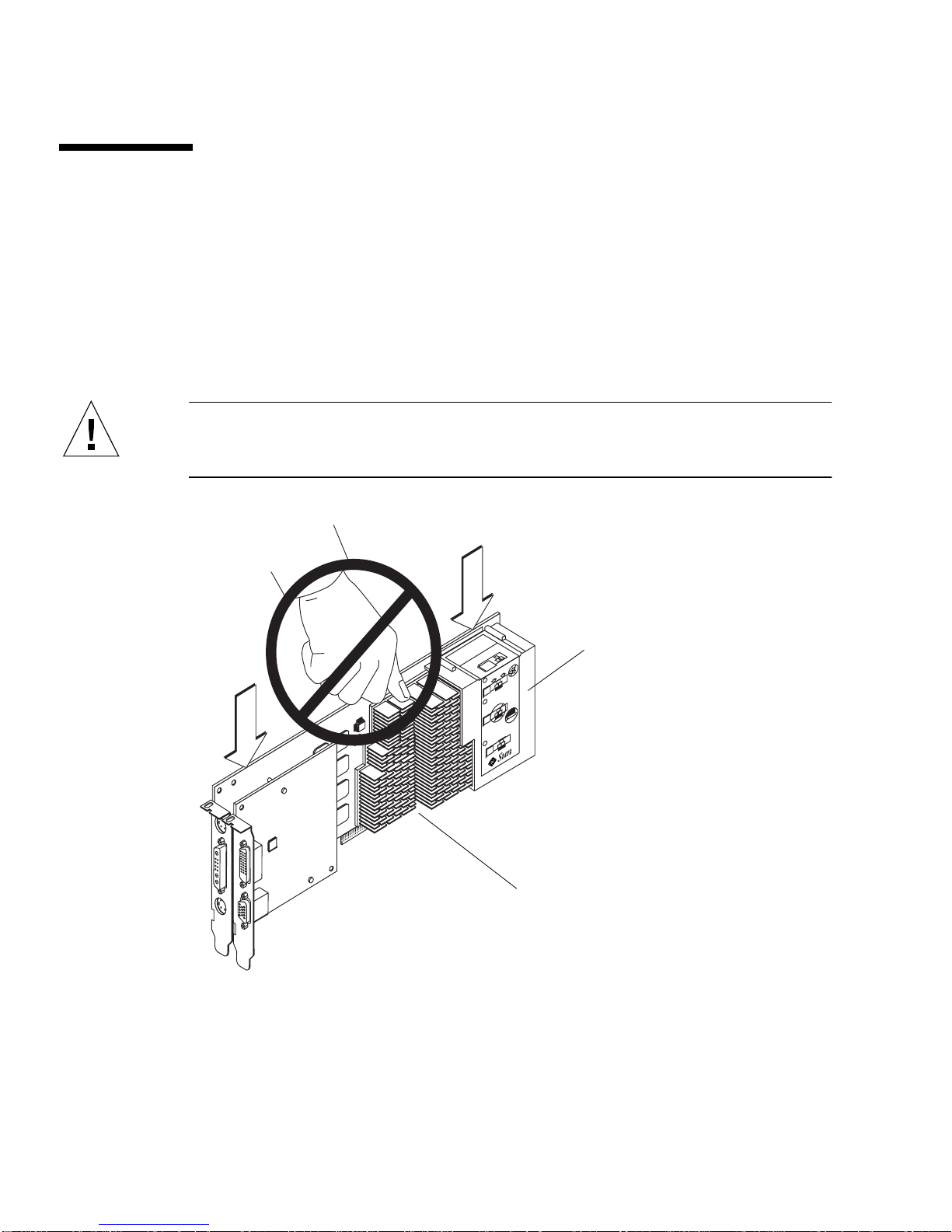
3. Holding the two upper corners of the graphics board, carefully push the board
straight down into the UPA bus connector until the board is fully seated
(
FIGURE 3-2).
Caution – When installing the Sun XVR-1000 graphics accelerator into your system
UPA slot, do not touch the graphics board heatsinks. Only apply pressure to the
graphics board as indicated by the arrows shown in FIGURE 3-1.
Installation
instruction
label
Insert can straight into
1
slot.
Push down firmly on
2
card until it is completely
inserted. Gold contacts
must not be visible.
double check that card
3
is completely inserted.
microsystems
Heatsinks
FIGURE 3-1 Installing the Sun XVR-1000 Graphics Accelerator
The Sun XVR-1000 graphics accelerator shroud also contains labeling with
installation instructions. See
FIGURE 3-1.
22 Sun XVR-1000 Graphics Accelerator Installation and User’s Guide • April 2002

Removing the Hardware
1. Turn off the power to your system, disconnect cabling, and open the enclosure.
2. Remove the Sun XVR-1000 graphics accelerator by pulling on the ends and gently
rocking the board until you remove the graphics board from the UPA slot
(
FIGURE 3-2).
Insert can straight into
1
slot.
Push down firmly on
2
card until it is completely
inserted. Gold contacts
must not be visible.
double check that card
3
is completely inserted.
microsystems
FIGURE 3-2 Removing the Sun XVR-1000 Graphics Accelerator
Chapter 3 Installing the Sun XVR-1000 Graphics Accelerator Hardware 23

System Configurations
TABLE 3-1 shows possible Sun XVR-1000 graphics accelerator configurations in the
supported Sun systems.
TABLE 3-1 Sun XVR-1000 Graphics Accelerator and System Hardware Configurations
Sun System UPA Slots Maximum Graphics Board Configuration
Sun Ultra 60 system
(see Note below)
Sun Ultra 80 system 2 2
Sun Blade 1000 system 2 2
Sun Blade 2000 system 2 2
21
Note – Although the Sun Ultra 60 system has two UPA bus connector slots, the UPA
slots are too close together to accommodate more than one Sun XVR-1000 graphics
accelerator.
24 Sun XVR-1000 Graphics Accelerator Installation and User’s Guide • April 2002

CHAPTER
4
Using Sun XVR-1000 Graphics
Accelerator Features
This chapter provides Sun XVR-1000 graphics accelerator feature information.
■ “Sun XVR-1000 Graphics Accelerator Multistreaming” on page 25
■ “Dynamic Multisample Antialiasing” on page 34
Sun XVR-1000 Graphics Accelerator
Multistreaming
The Sun XVR-1000 graphics accelerator has two possible video streams which may
drive one of four output ports (13W3, DVI-D, HD-15 and S-video). This section
describes how to tell the configuration program “fbconfig” which stream to
program and how to direct that stream output to the desired port.
When there are two Sun XVR-1000 graphics accelerators in the system, they are
numbered from 0.
trailing component to serve as a shorthand, such as “gfb0” for “/dev/fbs/gfb0”.
TABLE 4-1 Sun XVR-1000 Graphics Accelerator Device Names
Device Name Description
/dev/fbs/gfb0 Use explicitly for graphics board 1.
/dev/fbs/gfb1 Use explicitly for graphics board 2.
TABLE 4-1 gives the device names to use. fbconfig allows the
25

Multistream Options
There are four options from which to choose.
Option 1
In Option 1, only one output is active.
■ Benefits — Maximum resolution 1920 × 1200
■ Drawbacks — None
Frame Buffer
Stream A
13W3
Option 2
In Option 2, only one output is active.
■ Benefits — Maximum resolution 1920 × 1200
■ Drawbacks — Not all resolutions are supported (see TABLE A-2).
Frame Buffer
Stream B
DVI-D
S-video
HD15
26 Sun XVR-1000 Graphics Accelerator Installation and User’s Guide • June 2002
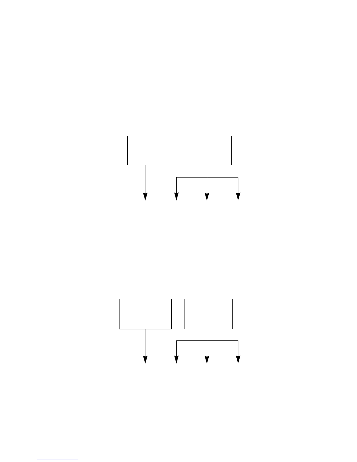
Option 3
In Option 3, two outputs are active where one large frame buffer is displayed across
both monitors.
■ Benefits — Two monitor support without the use of Xinerama software.
Can move windows between screens or a window across screens.
■ Drawbacks — Maximum resolution of 1280 × 1024 on each monitor.
Both resolutions must be identical.
Frame Buffer
Stream B
HD15
13W3
Stream A
DVI-D S-video
Option 4
In Option 4, two outputs are active and independent.
■ Benefits — Two monitor support.
The resolutions need not be identical.
■ Drawbacks — Cannot move windows between displays (no Xinerama mode).
Slowest mode of operation.
Frame Buffer
Stream A
Frame Buffer
Stream B
13W3
DVI-D
Chapter 4 Using Sun XVR-1000 Graphics Accelerator Features 27
S-video
HD15
Setting Up Option 1 (Default)
This option enables the 13W3 port output only. This is the mode the system uses if
no other fbconfig commands have been given.
Example
The following example returns the system to Option 1.
1. Disable doublewide mode. Type:
fbconfig -dev gfb0 -doublewide disable
2. Enable Stream A. Type:
fbconfig -dev gfb0 -active a
3. Select the desired screen resolution. Type:
fbconfig -dev gfb0 -res SUNW_STD_1280x1024x76
To find all possible Sun XVR-1000 graphics accelerator resolutions, type:
fbconfig -res \?
28 Sun XVR-1000 Graphics Accelerator Installation and User’s Guide • June 2002
Setting Up Option 2
This option enables the DVI-D or HD-15 port output.
Example
The following example sets up this option.
1. Disable doublewide mode. Type:
fbconfig -dev gfb0 -doublewide disable
2. Enable Stream B. Type:
fbconfig -dev gfb0 -active b
3. Select either the DVI-D or HD-15 port. Type:
fbconfig -dev gfb0 -stream b -port dvid
or
fbconfig -dev gfb0 -stream b -port hd15
4. Select the desired screen resolution. Type:
fbconfig -dev gfb0 -res SUNW_STD_1280x1024x76
To find all possible Sun XVR-1000 graphics accelerator resolutions, type:
fbconfig -res \?
To set up the S-video port, see Appendix B.
Chapter 4 Using Sun XVR-1000 Graphics Accelerator Features 29

Setting Up Option 3
This option enables two monitor support without the use of Xinerama software. This
means that the Sun XVR-1000 graphics accelerator creates one wide frame buffer,
displayed across two screens.
Example
The following example sets up this option.
1. Enable both streams, sharing a single frame buffer. Type:
fbconfig -dev gfb0 -doublewide enable
2. Select either the DVI-D or HD-15 port for the second monitor screen. Type:
fbconfig -dev gfb0 -stream b -port dvid
or
fbconfig -dev gfb0 -stream b -port hd15
3. Select the desired screen resolution. Type:
fbconfig -dev gfb0 -res SUNW_STD_1280x1024x76
To find all possible Sun XVR-1000 graphics accelerator resolutions, type:
fbconfig -res \?
30 Sun XVR-1000 Graphics Accelerator Installation and User’s Guide • June 2002

Setting Up Option 4
This option allows independent resolution setting of each stream.
Note – Stream option 4 is not supported in Xinerama. X windows and Sun OpenGL
for Solaris performance may be noticeably degraded in this mode. Many resources
(for example, Color LUTs and WID entries) are managed independently and the two
streams compete with each other.
Use stream option 3 whenever possible for a dual stream configuration.
Example
The following example sets up this option.
1. Select either the DVI-D or HD-15 port for the second monitor screen. Type:
fbconfig -dev gfb0 -stream b -port dvid
or
fbconfig -dev gfb0 -stream b -port hd15
2. Select an independent screen resolution for each frame buffer. Type:
fbconfig -dev gfb0a -res SUNW_STD_1280x1024x76
fbconfig -dev gfb0b -res SUNW_STD_1152x900x66
3. To enable both streams, both devices /dev/fbs/gfb0a and /dev/fbs/gfb0b
must appear in the /etc/dt/config/Xservers file.
For example:
:0 Local local_uid@console root /usr/openwin/bin/Xsun -dev
/dev/fbs/gfb0a -dev /dev/fbs/gfb0b
Chapter 4 Using Sun XVR-1000 Graphics Accelerator Features 31

To find all possible Sun XVR-1000 graphics accelerator resolutions, type:
fbconfig -res \?
TABLE A-2 in Appendix A for all valid screen resolution combinations.
See
To set up the S-video port, see Appendix B.
Port Selection
Stream B allows three different ports to be selected.
● To route Stream B to the HD-15 connector on the daughter board, use this
command:
# fbconfig -stream b -port hd15
● To route Stream B to the DVI-D connector on the daughter board, use this
command:
# fbconfig -stream b -port dvid
● Selecting the S-video port Stream B is automatic when the following video
resolutions are selected for Stream B:
■ SUNW_NTSC_640x480x66
■ SUNW_PAL_640x480x60
Note – For stream B to be active, it must be selected as described in the stream
section (“Multistream Options” on page 26). You must turn on doublewide mode,
or set the active stream to “b.”
32 Sun XVR-1000 Graphics Accelerator Installation and User’s Guide • June 2002
Multicard Setup
To use three (or four) video streams (monitors), you need to use two graphics
boards, and link those boards with Xinerama.
With three streams, one would be doublewide and one would be “normal.” For four
streams, both would be doublewide. For example, for the steps to create the
following monitor setup:
gfb0 (13W3) to monitor 1
gfb0 (HD15) to monitor 2
gfb1 (13W3) to monitor 3
1. Configure each Sun XVR-1000 graphics accelerator as follows:
# fbconfig -dev gfb0 -doublewide enable
# fbconfig -dev gfb0 -stream b -port hd15
# fbconfig -dev gfb1 -doublewide disable
# fbconfig -dev gfb1 -active a
2. Link the two graphics boards together with Xinerama in the Xservers file, as
shown:
(likely already defaulted to this)
:0 Local local_uid@console root /usr/openwin/bin/Xsun +xinerama
-dev /dev/fbs/gfb0 -dev /dev/fbs/gfb1
Chapter 4 Using Sun XVR-1000 Graphics Accelerator Features 33

Dynamic Multisample Antialiasing
Multisampling (full-scene dynamic multisample antialiasing) removes the jagged
edges on 3D data. An image is sampled at a higher resolution than the screen,
typically four to 16 samples per pixel. This method yields improved images, but at
the price of increased render time.
The Sun XVR-1000 graphics accelerator has 72 Mbytes of memory for the frame
buffer so that the image can be multisampled at up to 16 samples per pixel in a
single pass, depending on the resolution. The higher number of samples per pixel,
the better the image quality but the longer the display time. Depending on the
screen resolution (
improve image quality.
You can get better sample densities with dynamic mode if the window is smaller
then the screen size.
Use a combination of the fbconfig command and/or environmental variables to
invoke multisampling. You can enable multisample mode for a particular OpenGL
application or for all OpenGL applications.
Enabling Multisampling for a Specific OpenGL
TABLE 4-3), the number of samples per pixel can be increased to
Application
1. Set the multisample environmental variable.
This enables multisampling for the current window:
# setenv ZFB_USE_MSB
2. For this example, set the maximum sample usage to four samples per pixel:
# setenv ZFB_USE_MSB 4
34 Sun XVR-1000 Graphics Accelerator Installation and User’s Guide • June 2002

3. Set the ZFB_SHOW_DENSITY environment to display sample density when an
application is launched.
# setenv ZFB_SHOW_DENSITY
The output also shows value changes as the window is resized.
4. Launch your application.
The followings shows an example of setting the environments, launching the
application, and its output.
# setenv ZFB_USE_MSB 4
# setenv ZFB_SHOW_DENSITY
#
(
run OpenGL application
ogl_zfb: Auto multisample buffer mode
ogl_zfb: report sample density changes
multisample (s,b,p,tp,w,h):5,0,12,12,512,436
multisample (s,b,p,tp,w,h):8,0,12,12,426,350
Where: s = sample density, b = reserved, p = reserved, tp = reserved, w = window
width, h = window height.
)
Note – In the above example, the window was resized from 512 × 436 to 426 × 350.
Enabling Multisampling for All OpenGL
Applications
1. Use fbconfig to enable all OpenGL application windows for dynamic
multisampling.
# fbconfig -dev /dev/fbs/gfb0 -multisample auto dynamic -samples max
Note – When using the auto option switch, all OpenGL applications are
multisampled. If you use the enable switch, only those that use the multisample
APIs will be multisampled.
Chapter 4 Using Sun XVR-1000 Graphics Accelerator Features 35

2. Log out, then log back in to restart the X-server for the changes to take effect.
This enables multisampling for all OpenGL applications. The maximum sample size
is 16 samples per pixel. The sample size is automatically allocated based on available
memory when each application is started or resized. This means that each
application is at lower than 16 samples per pixel. You can set the sample to a smaller
size so that the first application does not use up the most memory.
If you set the environmental variable ZFB_SHOW_DENSITY in each application
window before you launch an application, the previously shown multisample
information for that application is displayed.
TABLE 4-2 describes the fbconfig -multisample options.
-multisample
[enable | disable | auto] [static | dynamic]
TABLE 4-2 Multisample Option Descriptions
Option Description
disable No multisample is possible.
enable Multisample is possible but is selected on a per application basis.
auto All OpenGL applications are rendered using multisampling.
static Multisample allocation occurs at startup/configuration load time.
The configuration samples-per-pixel parameter specifies the depth
that is pre-allocated.
dynamic A buffer is allocated for each OpenGL task.
TABLE 4-3 lists how many samples per pixel are supported at various maximum 3D
resolutions:
TABLE 4-3 Sun XVR-1000 Graphics Accelerator Multisampling Support
Maximum 3D resolution Single display Dual display Stereo (112 Hz)
1920 × 1200
× 1200
1600
× 1000 2
1600
× 1024 2 2
1280
× 900 3 2
1152
× 768 5 2 4
1024
36 Sun XVR-1000 Graphics Accelerator Installation and User’s Guide • June 2002

TABLE 4-3 Sun XVR-1000 Graphics Accelerator Multisampling Support (Continued)
Maximum 3D resolution Single display Dual display Stereo (112 Hz)
960 × 680 N/A 6
× 600 8 4 8
800
× 480 16 6 12
640
Note – TABLE 4-3 is for static mode multisampling but is applicable for dynamic
mode if the application is running the whole screen size. You can get better sample
densities with dynamic mode if the window is smaller then the screen size.
Chapter 4 Using Sun XVR-1000 Graphics Accelerator Features 37

38 Sun XVR-1000 Graphics Accelerator Installation and User’s Guide • June 2002

CHAPTER
5
Sun XVR-1000 Graphics Accelerator
Frame Locking and Buffer Swap
Synchronization
This chapter describes Sun XVR-1000 graphics accelerator frame locking and buffer
swap synchronization.
■ “Sun XVR-1000 Graphics Accelerator Frame Lock System” on page 39
■ “Buffer Swap Synchronization” on page 40
■ “Creating a Multiscreen Application” on page 41
■ “Configuring Sun XVR-1000 Graphics Accelerators for Frame Locking” on
page 42
■ “Frame Lock Cable Assembly” on page 44
■ “Connecting the Frame Lock Cable Assembly” on page 46
Sun XVR-1000 Graphics Accelerator
Frame Lock System
The frame lock synchronization feature enables vertical retracing to occur
simultaneously on each Sun XVR-1000 graphics accelerator subsystem. The frame
lock cable assembly is used to daisy-chain two or more Sun XVR-1000 graphics
accelerator subsystems. Vertical retrace synchronization eliminates flicker between
multiscreen displays. You can frame lock two or more Sun XVR-1000 graphics
accelerator subsystems across two or more computer systems.
Frame locking is often necessary when running in stereo in a multihead
environment. All the displays can be synchronized so that the left and right views
can be seen correctly through one set of LCD stereo glasses.
39

When frame buffers are frame locked, you should make sure they are all running at
the same video resolution and vertical retrace rate (see fbconfig -help for details).
See “Configuring Sun XVR-1000 Graphics Accelerators for Frame Locking” on
page 42.
To use the frame lock features, the frame lock cable assembly is required. See “Frame
Lock Cable Assembly” on page 44 for installation.
To order the frame lock cable assembly, call Sun telesales at 1-800-786-0404 and
request spare part number 530-2754. You can also order the frame lock cable
assembly through the Sun store (http://store.sun.com) by ordering this part
number under spare parts.
By default, two channels are not frame locked.
Buffer Swap Synchronization
Buffer swap synchronization enables a simultaneous swap of buffer memory
contents on all Sun XVR-1000 graphics accelerator subsystems to maintain image
quality and to enable continuity between scenes on all applicable displays. This
feature, however, is not applicable across two or more systems. The display can be a
monitor or a large wall screen image displayed by a projector. See “Creating a
Multiscreen Application” on page 41 in this section for an example of creating a
multiscreen application.
Note – if you frame lock multiple computer systems, only the frame lock feature
will operate (that is, the Buffer Swap Synchronization feature is not available across
multiple computer systems).
40 Sun XVR-1000 Graphics Accelerator Installation and User’s Guide • June 2002

Creating a Multiscreen Application
The following is a programming example of how to create a Buffer Swap
Synchronization (multiscreen) application.
Main program:
1. Create n full screen windows, one per screen.
2. Create n rendering threads and associate one thread per screen.
3. Create a master thread to synchronize rendering threads.
4. Execute main window system event loop.
Master Thread run method:
1. Do the following in a loop:
a. Notify all rendering threads to render a frame (possibly in response to an
event).
b. Wait for all rendering threads to finish rendering.
c. Notify all rendering threads to swap buffers.
d. Wait for all rendering threads to finish swapping.
Render Thread(s) run method:
1. Create OpenGL context for this thread’s window.
2. Make context current to this thread.
3. Initialize OpenGL context state.
4. Do the following in a loop:
a. Wait for master thread notification.
b. Render image to back buffer for this screen.
c. Notify master thread that this thread is done rendering.
d. Wait for master thread notification.
e. Swap buffers.
f. Notify master thread that this thread is done swapping.
Chapter 5 Sun XVR-1000 Graphics Accelerator Frame Locking and Buffer Swap Synchronization 41
Configuring Sun XVR-1000 Graphics
Accelerators for Frame Locking
1. Designate a Sun XVR-1000 graphics accelerator as the master.
You may use the Sun XVR-1000 graphics accelerator that serves as the boot/console
head for that system.
Refer to the boot -r man page for device location and device numbering
information for how devices are numbered based on their physical location. For
frame lock, you may select any device (that is, gfb0, gfb1, gfb2,...and so on) to be
the master Sun XVR-1000 graphics accelerator device.
2. Make sure that each Sun XVR-1000 graphics accelerator installed has the same
monitor resolution as the one in master mode.
a. Check the resolution of an Sun XVR-1000 graphics accelerator by using the
fbconfig command.
For example:
# fbconfig -dev /dev/fbs/gfb0 -prconf
You must repeat this command for each Sun XVR-1000 graphics accelerator in the
system or systems.
b. Change the resolution of a Sun XVR-1000 graphics accelerator using the
fbconfig command.
If the resolution on each Sun XVR-1000 graphics accelerator is not the same, you
must change it to match the Sun XVR-1000 graphics accelerator in master mode.
You must configure each board separately (that is, for gfb1, gfb2, gfb3, and so
on).
For example:
# fbconfig -dev /dev/fbs/gfb0 -active a -res 1280x1024x76
# fbconfig -dev /dev/fbs/gfb1 -active a -res 1280x1024x76
Log out of the X window system, and then log back in for the resolutions to take
effect.
42 Sun XVR-1000 Graphics Accelerator Installation and User’s Guide • June 2002

3. Set the master and slave graphics boards.
For example,
# fbconfig -dev /dev/fbs/gfb0 -master a -stream a -slave disable
# fbconfig -dev /dev/fbs/gfb1 -master input -stream a -slave enable external
You need to run these last two commands, setting each master and slave graphics
board, each time you log into your X window system.
Note – The -master and -slave options are only implemented as immediate
commands. They take effect when you run the fbconfig command, and are not
saved when you exit the X window system. When you restart the X window system,
all graphics boards and streams return to -master a and -slave disable modes.
4. Connect the frame lock cable to each Sun XVR-1000 graphics accelerator.
Make sure to first connect the frame lock cable master mode connector to the master
Sun XVR-1000 graphics accelerator, gfb0 in the above example. See the section
“Frame Lock Cable Assembly” on page 44.
Your system is now ready for frame locking.
Chapter 5 Sun XVR-1000 Graphics Accelerator Frame Locking and Buffer Swap Synchronization 43
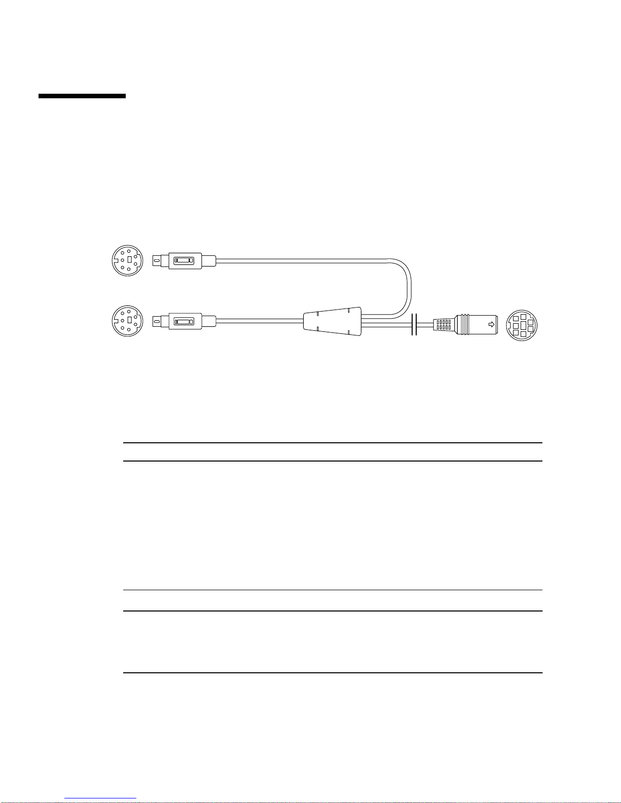
Frame Lock Cable Assembly
The frame lock cable assembly, FIGURE 5-1, is a Y-shaped cable assembly with three
connectors. Use this assembly to daisy-chain multiple Sun XVR-1000 graphics
accelerators within a computer system.
Slave mode connector
Master mode connector
Daisy-chain and stereo
glasses connector
FIGURE 5-1 Frame Lock Cable Assembly
TABLE 5-1 Frame Lock Cable Connections
Frame Lock Connector Description
Master connector
(shortest male cable)
Slave connector
(longest male cable)
Daisy-chain/stereo
glasses connector
(female connector)
Connects into the stereo connector located on the Sun XVR-1000
graphics accelerator that is designated as the master device. Also
plugs into the daisy-chain connector for slave Sun XVR-1000
graphics accelerators.
Connects into the stereo connector located on the Sun XVR-1000
graphics accelerator that is designated as a slave device.
Can connect a pair of stereo glasses directly into this connector. Or
the connector can be used to daisy-chain to other frame lock cables
for slave Sun XVR-1000 graphics accelerator devices.
Note – There can only be one master Sun XVR-1000 graphics accelerator device. You
must configure all other Sun XVR-1000 graphics accelerator devices as slaves. See
the section “Configuring Sun XVR-1000 Graphics Accelerators for Frame Locking”
on page 42.
44 Sun XVR-1000 Graphics Accelerator Installation and User’s Guide • June 2002

Stereo Connector Pinout for Frame Lock
FIGURE 5-2 and TABLE 5-2 show the Sun XVR-1000 graphics accelerator stereo
connector and pinout signals.
7
4
2
FIGURE 5-2 Sun XVR-1000 Graphics Accelerator Backplate Stereo Connector
TABLE 5-2 Sun XVR-1000 Graphics Accelerator Stereo Connector Pinout
Pin Signal
1 DIN7_RETURN (signal ground)
2 No connect
3 3D_GLASSES_PWR +11V
4 FIELD
5 Slave FIELD_IN
6 DRAWING_L
7 No connect
6
5
3
1
Chapter 5 Sun XVR-1000 Graphics Accelerator Frame Locking and Buffer Swap Synchronization 45

Typical Cable Wiring Application
TABLE 5-3 shows a typical wiring schematic for a master Sun XVR-1000 graphics
accelerator device and one or more slave Sun XVR-1000 graphics accelerator devices.
You should wire the second to nth slave devices exactly as the “Slave Male DIN7”
column in this table.
TABLE 5-3 Wiring Schematic for Frame Lock Cable Assembly
Master Male DIN7 Slave Male DIN7 Glasses Female DIN7
FIELD, pin 4----------------------FIELD_IN, pin 5--------------- FIELD, pin 4
DIN7_RETURN, pin 1----------DIN7_RETURN, pin 1------- DIN7_RETURN, pin 1
DRAWING_L, pin 6-------------DRAWING_L, pin 6----------DRAWING_L, pin 6 (see note)
3D_GLASSES_PWR, pin 3------------------------------------------3D_GLASSES_PWR, pin 3
Note – Use the “Glasses” connector to daisy-chain multiple cables to additional
slave Sun XVR-1000 graphics accelerator devices.
Connecting the Frame Lock Cable
Assembly
1. Locate the master Sun XVR-1000 graphics accelerator I/O backplate on the rear of
your system and connect the top of the frame lock cable assembly stereo
connector.
2. Connect the slave cable connector to a slave Sun XVR-1000 graphics accelerator
stereo connector.
3. Connect a second slave Sun XVR-1000 graphics accelerator, if applicable, or stereo
glasses to the daisy-chain/stereo connector (
FIGURE 5-3).
46 Sun XVR-1000 Graphics Accelerator Installation and User’s Guide • June 2002

First and second slave
Sun XVR-1000 graphics accelerators
Sun XVR-1000
graphics accelerator
stereo
connector
Designated
master Sun XVR-1000
graphics accelerator (M)
Top of frame lock
cable assembly
to master Sun XVR-1000
graphics accelerator
(S1)
Daisy-chain/stereo
connector
Cabling for second
slave Sun XVR-1000
graphics accelerator
(S2)
M
S1
S2
Slave cables
Optional
slave stereo glasses
FIGURE 5-3 Sun XVR-1000 Graphics Accelerator and Frame Lock Cable Assembly
Chapter 5 Sun XVR-1000 Graphics Accelerator Frame Locking and Buffer Swap Synchronization 47

48 Sun XVR-1000 Graphics Accelerator Installation and User’s Guide • June 2002

APPENDIX
A
Sun XVR-1000 Graphics Accelerator
Specifications
This appendix provides information on the Sun XVR-1000 graphics accelerator I/O
ports and screen resolution matrix.
■ “Sun XVR-1000 Graphics Accelerator I/O Ports” on page 49
■ “Screen Resolution Matrix” on page 51
Sun XVR-1000 Graphics Accelerator
I/O Ports
FIGURE A-1 shows the external I/O port connectors for the Sun XVR-1000 graphics
accelerator
FIGURE A-1 Sun XVR-1000 Graphics Accelerator External I/O Port Connectors
.
DVI-D port
Stereo port S-video port
13W3 port
HD-15 monitor port
49

The Sun XVR-1000 graphics accelerator provides a secondary video output stream
from either a DVI-D or HD-15 connector. The primary video output is through a
standard 13W3 connector. The secondary output is through one of the following:
■ HD-15 video connector for analog displays
■ DVI-D for digital input displays like flat panels
■ S-video connector for video devices like TV monitors or recording devices
The 13W3, HD-15, and DVI-D connectors all provide a DDC2B link. A DDC2B link
provides monitor query and control functions.
Note – If you are connecting a Sun XVR-1000 graphics accelerator HD-15 connector
to a 13W3-based display, an HD-15 to 13W3 video adapter is required.
Main Board Stereo Connector Pinout
FIGURE A-1 and TABLE A-1 show the Sun XVR-1000 graphics accelerator stereo
connector and pinout signals.
7
4
2
FIGURE A-2 Sun XVR-1000 Graphics Accelerator Backplate Stereo Connector
TABLE A-1 Sun XVR-1000 Graphics Accelerator Stereo Connector Pinout
Pin Signal
1 DIN7_RETURN (signal ground)
2 No connect
3 3D_GLASSES_PWR +11V
4 FIELD
6
5
3
1
50 Sun XVR-1000 Graphics Accelerator Installation and User’s Guide • June 2002

TABLE A-1 Sun XVR-1000 Graphics Accelerator Stereo Connector Pinout (Continued)
Pin Signal
5 Slave FIELD_IN
6 DRAWING_L
7 No connect
Daughter Board DVI-D Port
The daughter board DVI-D port shares the same video source as the daughter board
HD-15 and main board S-video ports. Only one of the main board S-video, daughter
board HD-15, or daughter board DVI-D ports can be active at any time.
The Sun XVR-1000 graphics accelerator supports the same resolutions for the
daughter board DVI-D port as for the daughter board HD-15 port.
When the main board 13W3 port is active at the same time as the DVI-D port, there
are restrictions on the supported combinations of resolutions. See “Screen Resolution
Matrix” on page 51.
Daughter Board HD-15 Port
The daughter board HD-15 port shares the same video source with the main board
S-video and daughter board DVI-D ports. Only one of the main board S-video,
daughter board HD-15, or daughter board DVI-D ports can be active at any time.
Screen Resolution Matrix
The Sun XVR-1000 graphics accelerator, with daughter board, supports two channels
of frame buffer area.
Channel 1 (main board 13W3 monitor port) and Channel 2 (daughter board HD-15
and DVI-D ports) frame buffer areas.
The first column of
resolution numbers correspond with the numbers representing the Channel 2
supported resolutions. A bullet indicates a combination of resolutions on Channel 1
and Channel 2 supported by the system.
TABLE A-2 lists the pairs of resolution supported by both
TABLE A-2 lists the Channel 1 supported resolutions. These
Appendix A Sun XVR-1000 Graphics Accelerator Specifications 51

TABLE A-2
Sun XVR-1000 Graphics Accelerator Supported Resolution Pairs Matrix
Channel 1
(main board)
0 None
1 640x480x60
2 640x480x72
3 640x480x75
4 800x600x75
5 960x680x108s
6 960x680x112s
7 1024x768x60
8 1024x768x70
9 1024x768x75
10 1024x768x77
11 1024x800x84
12 1152x900x66
13 1152x900x76
14 1152x900x120s
15 1280x768x56
16 1280x800x76
17 1280x800x112s
18 1280x1024x60
19 1280x1024x67
20 1280x1024x75
21 1280x1024x76
22 1280x1024x85
23 1280x1024x112s
24 1440x900x76
25 1600x1000x66
26 1600x1000x76
27 1600x1200x60
28 1600x1200x60d
29 1600x1200x75
30 1600x1280x76
31 1792x1344x60
32 1792x1344x75
33 1920x1080x60d
34 1920x1080x72
35 1920x1200x60d
36 1920x1200x70
37 1920x1200x75
38 640x480x60i
39 768x575x50i
Channel 2 (daughter board HD-15, daughter board DVI-D, main board S-video*)
0 1 2 3 4 5 6 7 8 9 10 11 12 13 14 15 16 17 18 19 20 21 22 23 24 25 26 27 28 29 30 31 32 33 34 35 36 37 38 39
• •••••••••••• • • ••••• •• • • • ••
•••••••••••••• • • ••••• •• • • • ••
•••••••••••••• • • ••••• •• • • • ••
•••••••••••••• • • ••••• •• • • • ••
•••••••••••••• • • ••••• •• • • ••
•••••• • ••••• • ••
••••• •••••• • ••
•••••••••••••• • • ••••• •• ••
•••••••••••••• • • •• • ••
•••••••••••••• • • •• ••
•••••••••••••• • • • ••
•••••••••••••• • • ••
•••••••••••••• • • ••
••••• • •••• • • ••
••••• ••
•••••••••••••• • • •• ••
••••• • ••••• • • ••
••••• ••
••••• • ••• • • ••
••••• • •• • • ••
••••• • • ••
••••• • • ••
••••• • • ••
•
••••• • ••
••••• •
•••••
••••• ••
••••• ••
••••• ••
•••• ••
• •
•
••••• ••
•••• ••
••••• •
•••• •
•••• •
•••••••••••••• • • ••••• •• • • • ••
•••••••••••••• • • ••••• •• • • ••
* S-video output supports only640 x480 forNTSC outputand 800 x 600 for PALoutput.
52 Sun XVR-1000 Graphics Accelerator Installation and User’s Guide • June 2002

APPENDIX
B
Setting Up S-Video
This appendix provides information for setting up S-video (NTSC and PAL video
formats) on the Sun XVR-1000 graphics accelerator.
■ “S-Video Configuration Option 1” on page 53
■ “S-Video Configuration Option 2” on page 54
■ “Example for Using Two Sun XVR-1000 Graphics Accelerators” on page 56
■ “Daughter Board Interactions” on page 57
Note – With S-video, you can cause the NTSC and PAL output to be a subwindow
of the main (13W3 channel) video outputs. It also allows you to pan the subwindow
within the full frame. No other secondary channel port (DVI-D or HD15) is available
while using S-video.
S-Video Configuration Option 1
This option allows S-video on video data stream 2, displaying nothing on
stream 1.
This setup dedicates all memory resources of the graphics board to the S-video port.
This is required for the largest multisampling depth of 16 samples per pixel. Another
board may be used if a large workspace is required for other purposes beyond the
one 640 × 480 window.
Note – This procedure assumes that you are setting up the first board as gfb0.
Substitute gfb0 with gfb1 for the second board.
53

1. Log in as superuser.
2. Set the resolution on the second stream.
■ For NTSC, type:
# fbconfig -dev /dev/fbs/gfb0 -res SUNW_NTSC_640x480x60
# fbconfig -dev /dev/fbs/gfb0 -active b -doublewide disable
■ For PAL, type:
# fbconfig -dev /dev/fbs/gfb0 -res SUNW_PAL_640x480x50
# fbconfig -dev /dev/fbs/gfb0 -active b -doublewide disable
3. Log out to restart the Xserver and verify the configuration data.
S-Video Configuration Option 2
This option allows S-video on video data stream 2 and a normal screen on
stream 1.
This setup shares the resources between the two streams. Multisample depth may be
reduced.
1. Log in as superuser.
2. Set the resolution on the first (normal) stream. Type:
# fbconfig -dev /dev/fbs/gfb0a -res SUNW_STD_1280x1024x76
Note – This is not the same resolution that is used for the default subdevice (gfb0).
This resolution needs to be set up independently in addition to gfb0.
Note – Any valid resolution can be used for gfb0a. The larger the resolution is,
however, the less memory is available for multisampling.
54 Sun XVR-1000 Graphics Accelerator Installation and User’s Guide • June 2002

3. Set the resolution on the second stream.
■ For NTSC, type:
# fbconfig -dev /dev/fbs/gfb0b -res SUNW_NTSC_640x480x60
■ For PAL, type:
# fbconfig -dev /dev/fbs/gfb0b -res SUNW_PAL_640x480x50
4. Add or change the Xservers file to include these devices.
You need to add device entries for /dev/fbs/gfb0a and /dev/fbs/gfb0b to the
/etc/dt/config/Xservers file. If an entry for /dev/fbs/gfb0 exists already,
delete it and add the two described devices, gfb0a and gfb0b. All other devices
should remain the same.
Note – Refer to the proper Xservers(1) man page and Xservers documentation
for further information.
5. Log out to restart Xserver and verify the configuration data.
S-Video Configuration Option 3
This option allows the S-video port and Stream B to be set up to capture any
subregion of Stream A after the window system is already running.
● Use the svideotool GUI application to set up and select this subregion:
% cd /opt/SUNWvidtools/bin/svideotool
Note – Stream B must not currently be in use for svideotool to be activated.
Appendix B Setting Up S-Video 55

Example for Using Two Sun XVR-1000
Graphics Accelerators
In this example the first board (gfb0) is used for S-video exclusively and the second
board (gfb1) is used normally.
1. Create the Xservers file:
:0 Local local_uid@console root /usr/openwin/bin/Xsun \
-dev /dev/fbs/gfb1 -dev /dev/fbs/gfb0
2. Specify resolutions for each board:
# fbconfig -dev /dev/fbs/gfb1 -res SUNW_STD_1280x1024x76
# fbconfig -dev /dev/fbs/gfb0 -res SUNW_NTSC_640x480x60
# fbconfig -dev /dev/fbs/gfb0 -active b -doublewide disable
3. Check the configuration status of the gfb1 device:
# fbconfig -dev gfb1 -propt
--- OpenWindows Configuration for /dev/fbs/gfb1 ---
OWconfig: machine
Video:
Resolution: SUNW_STD_1280x1024x76
Port (a): 13W3
Port (b): off
Multisample:
Samples Per Pixel: 16
Allocation Model: dynamic
Application Mode: auto
Screen:
Doublewide: disable
Active Stream: a
Offset/Overlap: [0, 0]
Clearpixel Value: 255
Gamma Correction Value: 2.20
56 Sun XVR-1000 Graphics Accelerator Installation and User’s Guide • June 2002

4. Check the configuration status of the gfb0 device:
# fbconfig -dev gfb0 -propt
--- OpenWindows Configuration for /dev/fbs/gfb0 ---
OWconfig: machine
Video:
Resolution: SUNW_NTSC_640x480x60
Port (a): off
Port (b): svideo
Multisample:
Samples Per Pixel: 16
Allocation Model: dynamic
Application Mode: auto
Screen:
Doublewide: disable
Active Stream: b
Offset/Overlap: [0, 0]
Clearpixel Value: 255
Gamma Correction Value: 2.20
The Video Mode SUNW_NTSC_640
×480×60 is used to initialize the resolution for
stream 2 for NTSC.
Note – By default, the first board in Xservers is the monitor on the left, and then
they are laid out left to right.
Daughter Board Interactions
If a daughter board is attached, video also might be visible on the HD-15 (VGA) or
DVI-D connectors. This raw RGB signal is also going to the NTSC/PAL encoder.
This signal is not meant to be used by normal monitors. The signal has an odd
aspect ratio and synchronization signals.
Appendix B Setting Up S-Video 57

58 Sun XVR-1000 Graphics Accelerator Installation and User’s Guide • June 2002

APPENDIX
C
Xinerama
Xinerama is an X windows feature available in Solaris 8 system software and
subsequent compatible releases for Sun graphics boards including the Sun XVR-1000
graphics accelerator.
When the window system is started in Xinerama mode, all windows can be
seamlessly moved across screen boundaries, thus creating one large, super highresolution, virtual display. With Sun OpenGL 1.2.1 for Solaris or subsequent
compatible releases, this functionality is extended to OpenGL applications. No
recompilation is necessary for a legacy application to work with Xinerama mode
across multiple screens, even if the application was compiled with an older version
of Sun OpenGL for Solaris.
To enable Xinerama mode (single logical screen) on multiscreen displays, add
+xinerama to the /usr/dt/config/Xservers file. For example:
:0 Local local_uid@console root /usr/openwin/bin/Xsun +xinerama
-dev /dev/fb0 -dev /dev/fb1
You need to install Sun OpenGL for Solaris version 1.2.1 (or later release) in order to
run your OpenGL-based applications seamlessly in multiscreen Xinerama mode;
older releases of OpenGL render only to one screen in the display.
59

60 Sun XVR-1000 Graphics Accelerator Installation and User’s Guide • June 2002

APPENDIX
D
Setting the Default Console Display
The console device defaults to the Sun XVR-1000 graphics accelerator. If another
frame buffer is installed, such as a PCI bus or UPA bus frame buffer, you may need
to change the default console display.
To set the Sun XVR-1000 graphics accelerator as the default console display:
1. At the ok prompt, type:
ok show-displays
The output prompts you to select a display device. For example:
a) /SUNW,gfb@1d,0
b) /SUNW,ffb@1e,0
q) NO SELECTION
2. Select the Sun XVR-1000 graphics accelerator device to be the default console
display.
In this example, select a, where SUNW,gfb is the Sun XVR-1000 graphics accelerator
device and 1d is the slot.
Enter Selection, q to quit: a
/SUNW,gfb@1d,0 has been selected.
Type ^Y ( Control-Y ) to insert it in the command line.
e.g. ok nvalias mydev ^Y
for creating devalias mydev for
/pci@1f,0/pci@5/SUNW,gfb@1d,0
61
3. Create an alias name for the Sun XVR-1000 graphics accelerator device.
The example output above shows mydev as the alias device name.
See Step 8 for instructions on renaming the device alias.
ok nvalias mydev <Control-Y> <Return>
4. Set the device that you selected to be the default console display device.
ok setenv output-device mydev
5. Store the alias name that you have created.
ok setenv use-nvramrc? true
6. Reset the output device environment.
ok reset
7. Rename an alias name for the Sun XVR-1000 graphics accelerator device
(optional).
You can simplify future OpenBoot
TM
PROM commands by creating an alias for the
Sun XVR-1000 graphics accelerator device. To do this,
a. Select the Sun XVR-1000 graphics accelerator device from the
show-displays menu.
b. Name the device (this example names the device as screen1).
ok nvalias screen1 <Control-Y> <Return>
c. Store the name as the alias.
ok nvstore
62 Sun XVR-1000 Graphics Accelerator Installation and User’s Guide • June 2002

d. Verify the alias.
ok devalias
The selected alias is displayed.
You can now refer to screen1 for the Sun XVR-1000 graphics accelerator device.
For example:
ok setenv output-device screen1
8. Reset the output device environment.
ok reset
9. Connect your monitor cable to the Sun XVR-1000 graphics accelerator monitor
connector on your system back panel (see
FIGURE A-1).
Appendix D Setting the Default Console Display 63

64 Sun XVR-1000 Graphics Accelerator Installation and User’s Guide • June 2002
 Loading...