

Page 1
Sun Fire™ X4150 Server
Embedded Lights Out Manager
Administration Guide
Sun Microsystems, Inc.
www.sun.com
Part No. 820-1855-10
September 2007, Revision A
Submit comments about this document at: http://www.sun.com/hwdocs/feedback
Page 2

Copyright ©2007 Sun Microsystems, Inc., 4150Network Circle,Santa Clara, California 95054, U.S.A.All rights reserved.
THIS PRODUCT CONTAINS CONFIDENTIAL INFORMATION AND TRADE SECRETS OF SUN MICROSYSTEMS, INC. USE,
DISCLOSURE OR REPRODUCTION IS PROHIBITEDWITHOUT THE PRIOREXPRESS WRITTEN PERMISSION OF SUN MICROSYSTEMS,
INC.
This distributionmay include materials developed by third parties. Sun, Sun Microsystems, the Sunlogo, Java, Netra, Solaris, StarOffice, Sun
Ray, Galaxy Sun Fire X and the SunSpectrum Pac (Sunburst design) logo are trademarksor registeredtrademarks of Sun Microsystems, Inc. in
the U.S.and other countries. Intel isa trademark or registered trademark of IntelCorporation or its subsidiaries inthe United States and other
countries. IntelInside is a trademark orregistered trademarkof Intel Corporation or itssubsidiaries in the United Statesand other countries.
This productis coveredand controlled by U.S. Export Control lawsand may be subject tothe export or import lawsin other countries. Nuclear,
missile, chemicalbiological weapons or nuclear maritimeend uses or end users,whether direct or indirect, are strictly prohibited. Export or
reexport tocountries subject to U.S. embargo orto entities identified on U.S.export exclusion lists, including, butnot limited to, the denied
persons andspecially designated nationals lists isstrictly prohibited.
Use ofany spare or replacement CPUs is limitedto repair or one-for-one replacement of CPUs in products exported in compliance withU.S.
export laws. Use of CPUsas product upgrades unless authorizedby the U.S. Government isstrictly prohibited.
Copyright ©2007 Sun Microsystems, Inc., 4150Network Circle,Santa Clara, California 95054, Etats-Unis.Tousdroits réservés.
CE PRODUIT CONTIENTDES INFORMATIONSCONFIDENTIELLES ET DES SECRETS COMMERCIAUX DE SUN MICROSYSTEMS, INC.
SON UTILISATION, SA DIVULGATION ET SA REPRODUCTION SONT INTERDITES SANS L’AUTORISATION EXPRESSE, ECRITE ET
PREALABLE DE SUN MICROSYSTEMS, INC.
Cette distributionpeut des éléments développés pardes tiers. Sun, Sun Microsystems, le logo Sun, Java, Netra, Solaris, StarOffice, Sun Ray,
Galaxy SunFire X et le logo SunSpectrumPac (Sunburst design) sont desmarques de fabrique ou des marques déposéesde Sun Microsystems,
Inc. auxEtats-Unis et dans d’autres pays.Intel est une marque de fabrique ouune marquedéposée de Intel Corporation oude sa filiale aux
Etats-Unis etdans d’autres pays. Intel Insideest une marque de fabrique ou unemarque déposéede Intel Corporation ou desa filiale aux EtatsUnis etdans d’autres pays.
Ce produitest soumis à la législationaméricaine sur le contrôle desexportations et peut être soumis à larèglementation en vigueur dans
d’autres paysdans le domaine des exportationset importations. Les utilisations finales,ou utilisateurs finaux, pour des armes nucléaires,des
missiles, desarmes biologiques et chimiques oudu nucléaire maritime, directement ou indirectement, sont strictement interdites.Les
exportations oureexportations vers les pays sousembargo américain,ou vers des entités figurantsur les listes d’exclusion d’exportation
américaines, ycompris, mais de maniere nonexhaustive, la liste de personnesqui font objet d’un ordre de ne pas participer, d’une façon directe
ou indirecte,aux exportations des produits ou des servicesqui sont régis par lalégislation américaine sur le contrôledes exportations et la liste
de ressortissantsspécifiquement désignés, sont rigoureusement interdites.
L’utilisation de pièces détachées ou d’unités centrales de remplacement est limitée aux réparations ou à l’échange standard d’unités centrales
pour les produits exportés, conformément à la législation américaine en matière d’exportation. Sauf autorisation par les autorités des EtatsUnis, l’utilisation d’unités centrales pour procéder à des mises à jour de produits est rigoureusement interdite..
Page 3

Contents
Preface xiii
1. Sun Fire X4150 server ELOM Overview 1
Sun Fire X4150 server ELOM Features 2
Embedded Lights Out Manager Common Tasks 2
Sun Fire X4150 server Default Settings 3
About the Preconfigured Administrator Account 4
About the Indicator and Fault LEDs 4
2. Connecting to the ELOM 5
About Connection Tasks 6
Connecting Using a Serial Connection 6
▼ To Connect Using a Serial Connection 6
Connecting Using Ethernet 7
3. Monitoring the Server System Using the Web-Based Interface 11
Using the Web-Based Interface 11
Browser and Software Requirements 12
Users and Privileges 12
Web-Based Interface Tasks 12
Accessing the ELOM Using a Web Browser 13
iii
Page 4

▼ To Access the ELOM Using a Web Browser 13
Viewing the System From the Web Browser 14
Viewing System and Component Information 16
▼ To View System Information 16
Viewing Version Information 16
▼ To View SP Version Information 16
Viewing Server Board Information 17
▼ To View Server Board Information 17
Viewing Component Information 17
▼ To View CPU Information 17
Viewing Memory Information 19
▼ To View Memory Information 19
Monitoring the System Sensors 19
▼ To Monitor the System Sensors 20
Reading Sensors 20
▼ To Read Sensors 20
Viewing a Sensor Summary 21
▼ To View a Sensor Summary 21
Monitoring Fans 23
▼ To Monitor Fans 23
Monitoring Temperatures 23
▼ To Monitor Temperatures 23
Monitoring Voltages 24
▼ To Monitor Voltage 24
Viewing and Managing the Event Log 24
▼ To Display the Event Log 25
▼ To View the Event Logs 25
▼ To Save the Event Log 25
iv Sun Fire X4150 Server Embedded Lights Out Manager Administration Guide • September 2007
Page 5

▼ To Clear the Event Log 26
4. Configuring, Managing and Maintaining the Server Using the Web-Based
Interface 27
Configuring the System 28
▼ To Configure the System 29
Configuring Network Settings 30
▼ To Configure the Network Settings 30
Configuring E-mail Notification 30
▼ To Configure E-mail Notification 30
Configuring Platform Event Filters 30
▼ To Configure a Platform Event Filter 31
Configuring System Management Access 33
▼ To access the System Management Access Submenus 33
Configuring the SSL Certificate 34
▼ To Configure the SSL Certificate 34
Configuring SNMP 34
▼ To Configure SNMP 35
▼ To Add an SNMP Community 35
▼ To Delete an SNMP Community 36
▼ To Modify an SNMP Community 36
▼ To Add an SNMP User 36
▼ To Delete an SNMP User 37
▼ To Edit an SNMP User 37
Configuring Active Directory Service 37
▼ To Configure Active Directory Service 38
Managing and Maintaining the System 38
Managing Users and Accounts 38
▼ To Add a User 39
Contents v
Page 6

▼ To Change a User Password or Privilege 41
▼ To Delete a User Account 41
▼ To Disable or Enable a User 41
Managing the System Locator Indicator LED 42
▼ To Control the State of the System Indicator LED 42
Managing the Front Panel and On-Board Fault LEDs 42
▼ To View the State of the Fault LEDs 43
▼ To Turn the Fault LEDs Off 43
Setting Power Control 44
▼ To Set Power Control 44
Resetting the Service Processor 44
▼ To Reset the Service Processor 44
Updating the Firmware 45
Updating the Firmware Using a Web Browser 45
▼ To Update the Firmware Using a Web Browser 46
Recovering from a Corrupt SP 46
▼ To Recover From a Corrupt SP 47
Managing Session Timeout 48
▼ To Set the Session Timeout 48
▼ To Disable the Session Timeout 48
Setting the Time 49
▼ To Set the Time 49
5. Using the Remote Console Application 51
Accessing the Remote Console 51
Requirements 51
CD and Diskette Redirection Operational Model 52
Starting the Remote Console Application 54
▼ To Start the Remote Console Application 54
vi Sun Fire X4150 Server Embedded Lights Out Manager Administration Guide • September 2007
Page 7

Setting Parameters for the Remote Console 55
▼ To Set Parameters for the Remote Console 55
Redirecting Keyboard, Video, Mouse, or Storage Devices 56
▼ To Redirect Keyboard and Mouse Devices 56
▼ To Redirect Storage Devices 57
Installing an Operating System on a Remote Server 58
▼ To Install an OS on a Remote Server Using a Virtual CD-ROM 58
Other Remote Options 59
6. Using IPMI 61
About IPMI 61
IPMItool 62
Sensors 62
Supported IPMI 2.0 Commands 63
7. Using the Command-Line Interface 69
Logging In to the CLI 69
Command Syntax 70
Managing the Host 72
Managing the Host State 72
Managing the Host Console 73
Viewing Host Sensors 73
Managing ELOM Network Settings 74
▼ To Display Network Settings 74
▼ To Configure Network Settings 74
Managing Local User Accounts With the CLI 75
Adding a User Account Using the CLI 76
▼ To Add a User Account Using the CLI 76
To Delete a User Account Using the CLI 76
Contents vii
Page 8

▼ To Display User Accounts Using the CLI 76
Configuring User Accounts 77
Managing Alerts 78
Displaying Alerts 78
▼ To Display Alerts 78
Displaying PET Target Properties 80
▼ To Display PET Target Properties 80
Configuring Alerts 80
Configuring the PET IP Address 81
▼ To Configure the PET IP Address 81
Configuring the PEF Global Controls 81
▼ To Configure the PEF Global Controls 82
Configuring the Event Filter Tables 82
▼ To Configure the Event Filter Tables 83
Displaying Version Information 85
To Display the Current SP Version Information 85
Updating the Firmware 86
▼ To Update the Firmware 86
8. Using Simple Network Management Protocol 89
About SNMP 89
How SNMP Works 89
SNMP MIB Files 90
MIBs Integration 90
SNMP Messages 91
Configuring SNMP on the ELOM 92
Adding Your Server to Your SNMP Environment 92
Configuring Receipt of SNMP Traps 92
Managing SNMP User Accounts 92
Contents viii
Page 9

Adding a User Account 92
Deleting a User Account 93
Configuring User Accounts 93
A. Command-Line Interface Reference 95
CLI Command Quick Reference 95
CLI Command Reference 99
Glossary 109
Index 131
Contents ix
Page 10

x Sun Fire X4150 Server Embedded Lights Out Manager Administration Guide • September 2007
Page 11

Figures
FIGURE 3-1 ELOM System Information Screen 14
FIGURE 3-2 An Excerpt of the View Event Logs Screen 25
FIGURE 4-1 The Configuration Screen 29
FIGURE 4-2 The Platform Event Filter Screen 32
FIGURE 4-3 The User Management Screen 40
FIGURE 4-4 The Fault LED Screen 43
FIGURE 5-1 Keyboard, Video, and Mouse Selections 57
FIGURE 8-1 Sun Server MIB Tree 91
xi
Page 12

xii Sun Fire X4150 Server Embedded Lights Out Manager Administration Guide • September 2007
Page 13

Preface
The Sun Fire X4150 Server Embedded Lights Out Manager Administration Guide
provides instructions for managing Sun servers using the Sun Fire X4150 server
(ELOM) with the service processor.
How This Document Is Organized
Chapter 1 describes the Embedded Lights Out Manager from an architectural
standpoint and indicates tasks that can be accomplished with the management
software.
Chapter 2 details the physical connections and how to communicate with your Sun
Fire X4150 server.
Chapter 3 describes how to use the web-based interface to monitor your server with
the embedded system management software.
Chapter 4 provides information about configuring, managing and maintaining the
server system with a web browser.
Chapter 5 describes how to use the remote console through the web-based interface.
Chapter 6 describes the Intelligent Platform Interface (IPMI) and how it can be used
to manage field replaceable units (FRUs) and system health independently of the
operating system.
Chapter 7 provides an alternative method of managing your server—through the
command-line interface (CLI).
Chapter 8 helps you understand the basics of the Simple Network Management
Protocol (SNMP) and how it is important to your server management.
xiii
Page 14

Appendix A gives you a quick reference to the commands you can use with
Embedded Lights Out Manager.
Glossary is a list of words and phrases and their definitions.
Using UNIX Commands
This document might not contain information about basic UNIX®commands and
procedures such as shutting down the system, booting the system, and configuring
devices. Refer to the following for this information:
■ Software documentation that you received with your system
■ Solaris™ Operating System documentation, which is at
http://docs.sun.com.
xiv Sun Fire X4150 Server Embedded Lights Out Manager Administration Guide • September 2007
Page 15

Typographic Conventions
Typeface
AaBbCc123 The names of commands, files,
AaBbCc123 What you type, when contrasted
AaBbCc123 Book titles, new words or terms,
* The settings on your web browser might differ from these settings.
*
Meaning Examples
Edit your.login file.
and directories; onscreen
computer output.
with onscreen computer output.
words to be emphasized.
Replace command-line variables
with real names or values.
Use ls -a to list all files.
% You have mail.
su
%
Password:
Read Chapter 6 in the User’s Guide.
These are called class options.
Yo u must be a superuser to do this.
To delete a file, enter rm filename.
Related Documentation
For the most up-to-date information about the Sun Fire X4150 server, navigate to
your server at http://docs.sun.com/app/docs/prod/sf.x4150.
Translated versions of some of these documents are also available at
http://docs.sun.com. Select a language from the drop-down list and navigate to the
Sun Fire X4150 server document collection using the High-End Servers product
category link. Available translations for the Sun Fire X4150 server include Simplified
Chinese, Traditional Chinese, French, Japanese, and Korean.
English documentation is revised more frequently and might be more up-to-date
than the translated documentation.
For all Sun hardware documentation, go to http://docs.sun.com/.
Preface xv
Page 16

Sun Documentation, Support, and
Training
Sun Function URL
Documentation http://www.sun.com/documentation/
Support http://www.sun.com/support/
Training http://www.sun.com/training/
Third-Party Web Sites
Sun is not responsible for the availability of third-party web sites mentioned in this
document. Sun does not endorse and is not responsible or liable for any content,
advertising, products, or other materials that are available on or through such sites
or resources. Sun will not be responsible or liable for any actual or alleged damage
or loss caused by or in connection with the use of or reliance on any such content,
goods, or services that are available on or through such sites or resources.
Sun Welcomes Your Comments
Sun is interested in improving its documentation and welcomes your comments and
suggestions, which you can submit at http://www.sun.com/hwdocs/feedback.
Please include the title and part number of this document with your feedback:
Sun Fire X4150 Server Embedded Lights Out Manager Administration Guide, 820-2705
xvi Sun Fire X4150 Server Embedded Lights Out Manager Administration Guide • September 2007
Page 17

CHAPTER
1
Sun Fire X4150 server ELOM Overview
This chapter serves as an overview of the capabilities of the Sun Fire X4150 server
Embedded Lights Out Manager (ELOM), and contains the following sections:
■ “Sun Fire X4150 server ELOM Features” on page 2
■ “Embedded Lights Out Manager Common Tasks” on page 2
■ “Sun Fire X4150 server Default Settings” on page 3
■ “About the Preconfigured Administrator Account” on page 4
■ “About the Indicator and Fault LEDs” on page 4
1
Page 18

Sun Fire X4150 server ELOM Features
The ELOM provides a dedicated system of hardware and supporting software that
enables you to manage your server independent of an operating system, and in lowpower situations. ELOM is composed of four components:
■ Web-based interface (requires JavaR v5 or later)
■ Command-line Interface (accessed via serial or ethernet using ssh)
■ IPMI v2
■ SNMP v3
You can access the ELOM using a web browser, secure shell (SSH), or via the Sun
Fire X4150 server’s serial port. Your server’s default network setting is configured as
DHCP for easy access via a web browser or SSH, and the ELOM output is directed
by default to the serial port.
Embedded Lights Out Manager Common Tasks
The following table shows common tasks and the management interfaces used to
perform each task.
TABLE 1-1 ELOM Common Tasks
Web-
Task IPMI
Redirect the system graphical console to a remote client
web browser.
Connect a remote diskette drive to the system as a
virtual diskette drive.
Connect a remote CD-ROM drive to the system as a
virtual CD-ROM drive.
Monitor system fans, temperatures, and voltages
remotely.
Monitor system BIOS messages remotely. Yes Yes Yes -
Monitor system operating system messages remotely. Yes Yes Yes -
2 Sun Fire X4150 Server Embedded Lights Out Manager Administration Guide • September 2007
Based
Interface CLI SNMP
-Yes - -
-Yes - -
-Yes - -
Ye s Ye s Ye s Ye s
Page 19

TABLE 1-1 ELOM Common Tasks (Continued)
Task IPMI
WebBased
Interface CLI SNMP
Interrogate system components for their IDs and serial
numbers.
Redirect the system serial console to a remote client. Yes - Yes -
Monitor system status (health check) remotely. Yes Yes Yes Yes
Interrogate system network interface cards remotely for
MAC addresses.
Manage user accounts remotely. Yes Yes Yes -
Manage system power status remotely (power on,
power off, power reset).
Monitor and manage environmental settings for key
system components (CPUs, motherboards, fans).
Ye s - Ye s Ye s
Ye s Ye s Ye s -
Ye s Ye s Ye s -
Yes Yes Yes Monitor
only
Sun Fire X4150 server Default Settings
Sun has configured the SP controller and SP firmware on your server to use the most
common default settings. It is unlikely that you will need to change any of these
defaults.
TABLE 1-2 SP Controller and Firmware Default Settings
System Component Default Status Action Required
Service processor card Preinstalled None
Service processor firmware Preinstalled None
IPMI interface Enabled None
Web-based interface Enabled None
Command-line interface (CLI) Enabled None
SNMP interface Enabled None
Chapter 1 Sun Fire X4150 server ELOM Overview 3
Page 20

About the Preconfigured Administrator Account
The ELOM is shipped with one preconfigured administrator account:
User name: root
Password: changeme
The preconfigured administrator account, root, is the default account. It cannot be
deleted or modified. You can only change the password for the root account. This
default account contains administrator privileges (read and write access) to all
service processor features and commands. For security reasons you should change
the root password and create an alternate user account that also has administrator
privileges. To change a user password or to create a new user, see Chapter 4.
If you’ve changed the root password, but have not created an alternate account, and
the new root password is lost or forgotten, you will have to reset the SP to return the
ELOM to its default settings. For information about how to do this, see“Resetting the
Service Processor” on page 44.
About the Indicator and Fault LEDs
The LEDs on the front and rear panel of your server allow you to manage the server
at a rudimentary level. The LEDs are helpful for indicating when a problem has
occurred, and you can use these LEDs in combination with the internal fault
indicator LEDs and buttons to troubleshoot and repair component failure issues.
However, using the ELOM it is possible not only to troubleshoot component failure
issues, but also to configure, manage, and maintain the server remotely and to
implement an effective preventative maintenance program. Using the ELOM as part
of a regular maintenance regimen allows you to take a proactive approach to server
repair. This can improve system performance and minimize downtime.
For information about the Indicator and Fault LEDs, see the Sun Fire X4150 Server
Service Manual.
For information about managing, maintaining, and configuring your server, see
Chapter 4 of this guide.
4 Sun Fire X4150 Server Embedded Lights Out Manager Administration Guide • September 2007
Page 21

CHAPTER
2
Connecting to the ELOM
This chapter details the ways to connect to and communicate with your Sun Fire
X4150 server. It contains the following sections:
■ “About Connection Tasks” on page 6
■ “Connecting Using a Serial Connection” on page 6
■ “Connecting Using Ethernet” on page 7
Note – You must install your server and configure the ELOM before communicating
with the server. Information about installing the server and configuring the ELOM is
available in the Sun Fire X4150 Server Installation Guide.
5
Page 22

About Connection Tasks
You have two methods to connect to the ELOM in your server:
■ Serial/Local
■ Ethernet/Remote
Both methods require making physical cable connections to the server and logging
in to the ELOM; refer to
TABLE 2-1 Methods of Connecting to the ELOM
TABLE 2-1.
Connection
Method
Serial, direct CLI only RJ-45
Ethernet CLI and
Supported
Interface
We b
browser
Required
Cable Comments/Description
Connect directly to the serial management port the on
serial
(supplied)
Ethernet
LAN
server with a terminal or laptop running terminal
emulation software.
You must know the ELOM’s Ethernet address.
Note: This is the only method that supports web
browser access.
Note – The ELOM supports a maximum of 10 active sessions, including serial, SSH,
and web browser sessions.
Connecting Using a Serial Connection
You access the ELOM CLI by connecting a terminal or a PC running terminal
emulation software to the RJ-45 serial port on the server using the supplied cable.
▼ To Connect Using a Serial Connection
1. Verify that your terminal, laptop, or terminal server is operational.
2. Configure the terminal device or terminal emulation software to use the
following settings:
■ 8,N,1: eight data bits, no parity, one stop bit.
6 Sun Fire X4150 Server Embedded Lights Out Manager Administration Guide • September 2007
Page 23

■ 9600 baud (default, can be set to any standard rate up to 57600).
■ Disable software flow control (XON/XOFF).
3. Connect a serial cable to the RJ-45 connection on the back of the server.
4. Connect the other end to the terminal or laptop.
5. Press Enter on the terminal device.
This action establishes the connection between the terminal device and the
ELOM. When the server has booted, the ELOM displays its login prompt:
SUNSPnnnnnnnnnn login:
The first string in the prompt is the default host name. It consists of the prefix
SUNSP and the ELOM’s MAC address. The MAC address for each ELOM is
unique.
6. Log in to the CLI.
Accounts created using the web browser are available for the CLI. If this is the
first login, you will need to use the preconfigured default account:
User name: root.
Password: changeme.
Once you have successfully logged in, the default command prompt appears:
->
You can now run CLI commands (Chapter 7 describes how to use the CLI).
To log out of the CLI
● Enter the following command:
-> exit
Connecting Using Ethernet
Ethernet connectivity provides full access to both the ELOM command-line interface
(CLI) and the web-based interface. Both connection options allow you to manage,
maintain, and configure the server remotely. This section contains the following two
connection procedures:
■ Connecting to the CLI. See Connecting to the CLI.
■ Connecting to the web-based interface. See Connecting to the Web-Based
Interface.
Chapter 2 Connecting to the ELOM 7
Page 24

Note – You will need the IP address of your ELOM, which you obtained during the
setup and installation of your server (see the Sun Fire X4150 Server Installation Guide).
Connecting to the CLI
Be sure that you have connected a LAN to the NET MGT 0 port on the server, and
that you have an SSH client installed on your remote system.
▼ To Connect to the CLI
1. If necessary start your SSH client.
2. To log in to the ELOM, enter the following command:
$ ssh username@ipaddress
username The user ID and ipaddress is the IP address of the ELOM. Accounts
created using the web browser are available for the CLI. If this is the first login,
you will need to use the preconfigured default account. For example,
$ ssh root@ipaddress
3. When prompted, enter the password for the username used in Step 2.
The password for root is changeme.
The CLI command prompt appears:
–>
For information about managing the server using the CLI, see Chapter 7. For
information about the default account, see “About the Preconfigured
Administrator Account” on page 3.
To Log Out of the CLI:
● Enter the following command:
–> exit
8 Sun Fire X4150 Server Embedded Lights Out Manager Administration Guide • September 2007
Page 25

Connecting to the Web-Based Interface
Be sure that you have connected a LAN to the NET MGT 0 port on the server.
▼ To Connect to the Web-Based Interface
1. Type the IP address of the ELOM into your web browser.
The login screen appears.
2. Type a user name and password.
Accounts created using the CLI are available for the web-based interface. If this is
the first login, you will need to use the preconfigured default account:
■ Default user name: root
■ Default password: changeme
For more information about the default account, see “About the Preconfigured
Administrator Account” on page 3.
3. Click Log In.
The web-based interface appears. Chapter 3 shows how to use the interface.
To Log Out of the web-based interface:
● Click the Log Out button.
The Log Out button is located in the upper right corner of the screen.
Chapter 2 Connecting to the ELOM 9
Page 26

10 Sun Fire X4150 Server Embedded Lights Out Manager Administration Guide • September 2007
Page 27

CHAPTER
3
Monitoring the Server System Using the Web-Based Interface
This chapter provides information about how to use the web-based interface and the
Sun Fire X4150 server software to monitor your server.
It includes the following sections:
■ “Using the Web-Based Interface” on page 11
■ “Accessing the ELOM Using a Web Browser” on page 13
■ “Viewing System and Component Information” on page 16
■ “Monitoring the System Sensors” on page 19
■ “Viewing and Managing the Event Log” on page 24
Note – You can monitor the rudimentary state of the server using the LED fault
light. A solidly lit amber LED indicates critical error. Further details about the fault
light can be found in your Service Manual. For information about controlling the state
of the fault LEDs see “To Control the State of the System Indicator LED” on page 42.
Using the Web-Based Interface
The web-based graphical user interface (GUI) allows you to use a standard web
browser to monitor and manage local and remote systems.
You can redirect the server’s console to a remote workstation or laptop system. This
requires configuring the remote system’s keyboard and mouse to act as the server's
keyboard and mouse. You can configure the diskette drive or CD-ROM drive on the
11
Page 28

remote system as if it were connected to the Sun server. You can also redirect
diskette images (.img files) and CD-ROM images (.iso files) for remote access.
Remote configuration issues are covered in Chapter 5.
Browser and Software Requirements
The web-based interface has been tested successfully with recently released
Mozilla™ Firefox and Internet Explorer web browsers, and might be compatible
with other web browsers.
The ELOM product is preinstalled on the Sun server. However, you need Java™
software on the client to perform redirection as described in Chapter 5.
Users and Privileges
After you log in to the web-based interface, you can perform basic software tasks,
Intelligent Platform Management Interface (IPMI) tasks, and system monitoring.
ELOM user accounts define what you can do by roles:
■ Administrator – Enables read/write access to all ELOM features, functions, and
commands.
■ Operator, User, and Callback – Enable limited access to ELOM features,
functions, and commands. For example, users with these permissions cannot
change their assigned roles or privileges.
For more information about users, including how to manage user accounts using the
web-based interface, see Chapter 4.
Web-Based Interface Tasks
Some of the common tasks you can perform using the web-based interface include:
Configuring connection methods:
■ Redirect the system’s console to a remote client browser.
■ Connect a remote diskette drive or diskette image to the system as a virtual
diskette drive.
■ Connect a remote CD-ROM drive or CD-ROM image to the system as a local or
virtual CD-ROM drive.
12 Sun Fire X4150 Server Embedded Lights Out Manager Administration Guide • September 2007
Page 29

Monitoring and managing system status:
■ Monitor the status of system fans, temperatures, and voltages remotely.
■ Monitor BIOS power-on self-test (POST) progress log entries remotely.
■ View, save, and clear system event logs.
■ Examine component information, including CPUs, DIMMs, voltages, and fans.
■ Power on, power off, power cycle, reset the system remotely, reboot and enter
the system BIOS, reboot and enter diagnostics (Pc-Check), and send NMI.
Managing and modifying system variables:
■ Manage user accounts locally and remotely.
■ Configure settings.
■ Update BIOS firmware.
Accessing the ELOM Using a Web Browser
The ELOM boots automatically when a Sun server is cabled appropriately and
plugged in to an AC power supply. This usually occurs within one minute.
However, if the management Ethernet is not connected, or if the ELOM's Dynamic
Host Configuration Protocol (DHCP) process fails due to the absence of a DHCP
server on the management network, the ELOM might take a few minutes longer to
boot.
Note – Disabling the use of the browser proxy server (if one is used) for access to
the management network might speed the browser response time.
▼ To Access the ELOM Using a Web Browser
1. To log in to the web-based interface, type the IP address of the ELOM in your
web browser.
The login screen appears.
2. In the login screen that appears, type the default user name and password.
Username: root
Password: changeme
Chapter 3 Monitoring the Server System Using the Web-Based Interface 13
Page 30
3. Click Log In.
The web-based interface appears.
To log out of the web-based interface:
● Click the Logout button in the upper right corner of the screen.
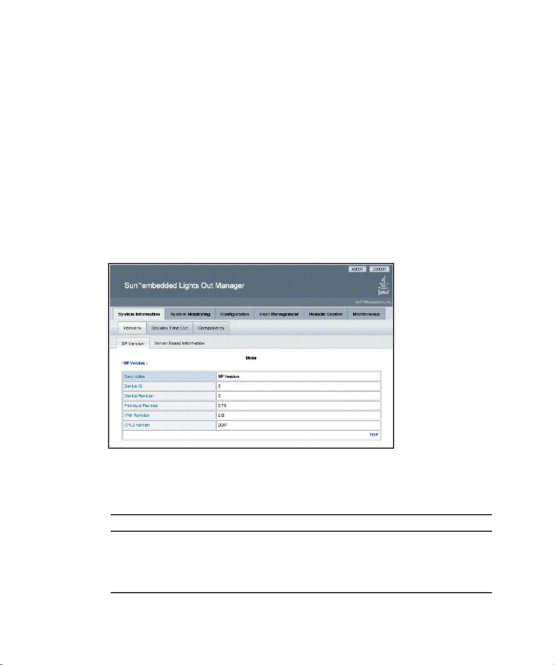
Viewing the System From the Web Browser
The system is equipped with a number of sensors that measure voltages,
temperatures, fan speed, and so on. The System Information tab shows the current
system status and provides access to the Version, Session Time-Out, and the
Components submenu tabs (see
FIGURE 3-1 ELOM System Information Screen
FIGURE 3-1).
TABLE 3-1 lists the ELOM main menu and submenu tabs and points to relevant
sections in this manual.
TABLE 3-1 ELOM Tab Detail Choices
Main Tab Submenu Tab Where to Find Details
System
Information
Server Board Information “Viewing Version Information” on page 16.
SP Version “Viewing Version Information” on page 16.
14 Sun Fire X4150 Server Embedded Lights Out Manager Administration Guide • September 2007
“Viewing System and Component Information”
on page 16.
Page 31

TABLE 3-1 ELOM Tab Detail Choices (Continued)
Main Tab Submenu Tab Where to Find Details
Session Time-Out “Managing Session Timeout” on page 48
Components “Viewing Component Information” on page 17
System
Monitoring
Sensor Reading “Monitoring the System Sensors” on page 19
Event Logs “Viewing and Managing the Event Log” on
page 24
Locator Indicator
Fault LED
“Managing the System Locator Indicator LED”
on page 42
Configuration
Network “Configuring Network Settings” on page 30
E-mail Notification “To Configure E-mail Notification” on page 30
Platform Event Filter “Configuring Platform Event Filters” on page 30
Clock Settings “Setting the Time” on page 49
System Management
Access
“Configuring System Management Access” on
page 33
“Recovering from a Corrupt SP” on page 46
User
Management
User Account “To Add a User” on page 39
ADS Configuration “To Configure Active Directory Service” on
page 38
Remote
Control
“Starting the Remote Console Application” on
page 54
Redirection “Redirecting Keyboard, Video, Mouse, or Storage
Devices” on page 56
Remote Power Control “Setting Power Control” on page 44
Hotkey Setup “To Set Parameters for the Remote Console” on
page 55
Maintenance
Firmware Upgrade “Updating the Firmware” on page 45
Reset SP “Resetting the Service Processor” on page 44
Chapter 3 Monitoring the Server System Using the Web-Based Interface 15
Page 32

The following section describes how to monitor the server using the web browser
and the Embedded Lights Out Manager software.
Viewing System and Component Information
The System Information tab provides information about system components, such as
the service processor (SP), the server board, the CPU, and the memory. Details are
found in the Versions and Components submenu tabs.
▼ To View System Information
● On the main menu, click the System Information tab.
The System Information submenu appears, allowing you to view the Versions,
Session Time-Out, and Components tabs.
Viewing Version Information
▼ To View SP Version Information
● From the Versions submenu, select the SP Version tab.
The SP Version screen appears, displaying information about the server board
installed in the system. It presents the information in a tabular format. For
example,
SP Version screen:
TABLE 3-2 Sample SP Information
Description SP Version
Device ID 5
Device Revision 0
16 Sun Fire X4150 Server Embedded Lights Out Manager Administration Guide • September 2007
TABLE 3-2 shows a sample of the SP information as it is displayed in the
Page 33

TABLE 3-2 Sample SP Information
Description SP Version
Firmware Revision 1.0
IPMI Revision 2.0
CPLD version 3041
Viewing Server Board Information
▼ To View Server Board Information
● From the Versions submenu, select the Server Board Information tab.
The Server Board Information screen appears, displaying information such as the
BIOS version and the serial number. It presents the information in a tabular
format.
displayed:
TABLE 3-3 Sample Server Board Information
Description Server Board Information
BIOS version: 1ADQWOO9
Manufacture Date: Wed Dec 31 23:59:59 1969
Product: Sun Fire X4150
Serial Number: 12345678901234
TABLE 3-3 show a sample of the server board information as it is
Viewing Component Information
▼ To View CPU Information
The CPU menu selection provides information about the processor.
Chapter 3 Monitoring the Server System Using the Web-Based Interface 17
Page 34

● From the System Information menu, click the Components submenu tab, then
select CPU.
The CPU information screen appears. The CPU information is presented in a
tabular format. A separate table of information is available for each of the
server’s CPUs, whether a CPU is installed or not.
TABLE 3-4 shows a sample of the
CPU information for CPU0:
TABLE 3-4 Sample CPU Information
CPU: 0
Status: Enable
Socket: CPU0
Manufacturer: Intel
Model:
Frequency:
18 Sun Fire X4150 Server Embedded Lights Out Manager Administration Guide • September 2007
Page 35

Viewing Memory Information
▼ To View Memory Information
● From the System menu, select Components, and then select Memory.
The Memory screen appears. It displays information about total memory
installed in your server; see
TABLE 3-5 Sample Memory Information
Description Memory Size Information
Total Memory Size:
The Memory screen also displays information about each DIMM installed in your
system, presenting it in a tabular format that includes such information as the
memory module number, the status, and module size; see
of the memory information for DIMM_A0.
TABLE 3-6 Sample Memory for DIMM_A0
Description Memory Information
Memory Module:
Status:
Socket:
Module Size:
Type:
Frequency:
TABLE 3-5.
12288 MB
TABLE 3-6 for a sample
1
Ok
DIMM_A0
1024MB
FBDIMM
667MHz
Monitoring the System Sensors
Sensors placed throughout the system provide information about the state of critical
server components. The sensors read temperature and voltage and report on
operational status. Using the System Monitoring submenu screens you can view the
these sensors and monitor the health of your server’s critical components. For
example, you can check the temperature of each CPU or DIMM and read the actual
DC voltage of each of the system’s power supply lines. The System Monitoring
Chapter 3 Monitoring the Server System Using the Web-Based Interface 19
Page 36

submenu screens also allows you to view and manage the system log, the Locator
Indicator LED, and the Fault LED. For information about the Locator Indicator LED
and the Fault LED, see “Managing the System Locator Indicator LED” on page 42.
▼ To Monitor the System Sensors
● On the main menu, click System Monitoring.
The System Monitoring submenu appears, allowing you to view the Sensor
Reading, Event Logs, Locator Indicator, and Fault LED tabs.
Reading Sensors
▼ To Read Sensors
● From the System Monitoring tab, click the Sensor Reading Tab.
The Sensor Reading tab allows you to select the Summary, Temperature, Voltage,
and Chassis Status tabs.
20 Sun Fire X4150 Server Embedded Lights Out Manager Administration Guide • September 2007
Page 37

Viewing a Sensor Summary
▼ To View a Sensor Summary
● From the Sensor Reading tab, select the Summary tab.
The Summary screen appears. It provides an overview of the status of the system
sensors. The screen provides the status of the Fault LED, the power, the
temperature of all critical components, and each of the monitored voltage lines.
For example,
the status of the Fault LED and the system power.
TABLE 3-7 Top Portion of the Summary Table Showing the Fault LED and Power Status.
TABLE 3-7 shows the top portion of the summary table summarizing
Fault LED Status
Power Status
TABLE 3-8 shows a detail of the Summary table that summarizes the status of each
On
Off
of the system fans.
TABLE 3-8 Detail of the Summary Table Showing the Status of the System Fans.
Fanbd1/FM1 :ok
Fanbd1/FM0 :ok
Fanbd1/FM3 :ok
Fanbd1/FM2 :ok
Fanbd1/FM5 :ok
Fanbd1/FM4 :ok
Fan Status
Fanbd0/FM1 :ok
Fanbd0/FM0 :ok
Fanbd0/FM3 :ok
Fanbd0/FM2 :ok
Fanbd0/FM5 :ok
Fanbd0/FM4 :ok
Fanbd0/FM7 :ok
Fanbd0/FM8 :ok
Chapter 3 Monitoring the Server System Using the Web-Based Interface 21
Page 38

TABLE 3-9 shows a detail of the Summary table that summarizes the status of the
temperature sensors.
TABLE 3-9 Detail of the Summary Table Showing the Status of the Temperature Sensors.
CPU 0 Temp :too high
Temperature Status
CPU 1 Temp :ok
Ambient Temp0 :ok
TABLE 3-10 shows a detail of the Summary table that summarizes the status of the
DC power supply lines.
TABLE 3-10 Detail of the Summary Table Showing the Status of the Power Supply Lines.
Vcc 12V :ok
Vtt 1.2V :ok
MCH 1.5V :ok
Vcc 3.3V :ok
Voltage Status
Vcc 5V :ok
NIC Vtt 1.2V :ok
Vcc 3.3V STB :ok
Vcc 2.5V STB :ok
Vcc 1.8V :ok
TABLE 3-11 shows a detail of the Summary table that summarized the status of the
systems power supplies.
TABLE 3-11 Detail of the Summary Table Showing the Status of the Power Supplies.
PS0 Under Volt :ok
PS1 Under Volt :ok
Power Status
22 Sun Fire X4150 Server Embedded Lights Out Manager Administration Guide • September 2007
PS0 OC Fault :ok
PS1 OC Fault :ok
Power Supply 0 :ok
Power Supply 1 :ok
Page 39

Monitoring Fans
▼ To Monitor Fans
● From the Sensor Reading tab, select the Fan tab.
The Fan screen appears, displaying the critical thresholds, the actual sensor
reading, and the status for each of the systems fans. The readings are in RPM.
The information is presented in tabular format.
information on the Fan screen. The sample is for the fan labeled Fanbd1/FM1.
TABLE 3-12 Sample of Fan Information for Fanbd1/FM1
Description Fanbd1/FM1
Lower critical threshold is readable: 1463
Upper critical threshold is readable: 14936
Sensor Reading: 13629
Status: ok
Monitoring Temperatures
TABLE 3-12 shows sample
▼ To Monitor Temperatures
● From the Sensor Reading tab, select the Temperature tab.
The Temperature screen appears, displaying the ambient chassis and CPU
temperatures. The temperatures are displayed in degrees celsius. The Sensor
Reading screen shows the current temperature reading.
Temperature information for CPU 0. A separate table is presented for each CPU
and each ambient sensor.
TABLE 3-13 Sample Temperature Monitor Readings
Description CPU 0 Temp
Upper noncritical threshold is readable: 93.0
Upper critical threshold is readable: 95.0
Sensor Reading: 54.0
Status: ok
Chapter 3 Monitoring the Server System Using the Web-Based Interface 23
TABLE 3-13 shows sample
Page 40

A similar panel is repeated for each monitored entity.
Monitoring Voltages
▼ To Monitor Voltage
● From the Sensor Reading tab, click the Voltage tab.
The Voltage screen appears. The Voltage screen displays the critical and
noncritical thresholds, the actual sensor reading, and the status for the nine
monitored DC system voltage lines. The Sensor Reading value represents the
actual voltage reading for that sensor.
Voltage screen. The sample is for the Vcc 12V line:
TABLE 3-14 Sample of the Voltage Monitor Screen
Description Vcc 12V
Lower noncritical threshold is readable: 11.999
Lower critical threshold is readable: 10.821
Upper noncritical threshold is readable: 12.837
Upper critical threshold is readable: 13.215
Sensor Reading: 12.081
Status: ok
TABLE 3-14 shows a sample from the
Viewing and Managing the Event Log
The Event Logs screen allows you to view and manage the system event log (SEL).
The SEL is a record of event occurrences. To record events in the SEL, you must have
previously determined which events require logging. See “Configuring Platform
Event Filters” on page 27.
24 Sun Fire X4150 Server Embedded Lights Out Manager Administration Guide • September 2007
Page 41

▼ To Display the Event Log
● From the System Monitoring tab on the main menu, click the Event Logs
submenu tab.
The Event Logs screen appears. The View Event Logs, Save Event Logs, and
Clear Event Logs submenus become available.
▼ To View the Event Logs
● From the Event Logs tab, select View Event Logs.
The system event log appears. Each entry in the log represents an action that
occurred on the system. The information is presented in a tabular format. The
system lists each action, rates the action’s severity, provides a time stamp, and
describes the event. The severity field includes icons for both Information and
Critical ratings.
FIGURE 3-2 An Excerpt of the View Event Logs Screen
FIGURE 3-2 shows an excerpt from the View Event Logs screen.
▼ To Save the Event Log
You might want to save the event log for administrative or diagnostic purposes.
1. From the Event Logs tab, click the Save Event Logs tab.
The Save Event Log screen appears.
2. Click the Save Event Log button to prompt the browser to ask you where to
save a copy of the event log.
3. Select the location, name the file (if necessary), and click save.
Chapter 3 Monitoring the Server System Using the Web-Based Interface 25
Page 42

▼ To Clear the Event Log
The Event Log might need to be cleared to signify a fresh procedure, or identify
system performance under load.
1. From the Event Logs tab, click Clear Event Log.
2. Click the Clear Event Log button to start a fresh event log.
26 Sun Fire X4150 Server Embedded Lights Out Manager Administration Guide • September 2007
Page 43

CHAPTER
4
Configuring, Managing and Maintaining the Server Using the Web-Based Interface
This chapter provides information about how to use a web browser and the Sun Fire
X4150 server software to manage your server. The sections include:
■ “Configuring the System” on page 28
■ “Managing and Maintaining the System” on page 38
This chapter addresses your local system. For information about how to redirect
your commands to a remote system, see Chapter 5.
27
Page 44

Configuring the System
The Configuration submenu tabs enable you to configure the network operation and
other important functions of the server. These functions are described in the
following sections:
■ “Configuring Network Settings” on page 30
■ “Configuring E-mail Notification” on page 30
■ “Configuring Platform Event Filters” on page 30
■ “Configuring System Management Access” on page 33
■ “Configuring SNMP” on page 34
■ “Configuring Active Directory Service” on page 37
28 Sun Fire X4150 Server Embedded Lights Out Manager Administration Guide • September 2007
Page 45
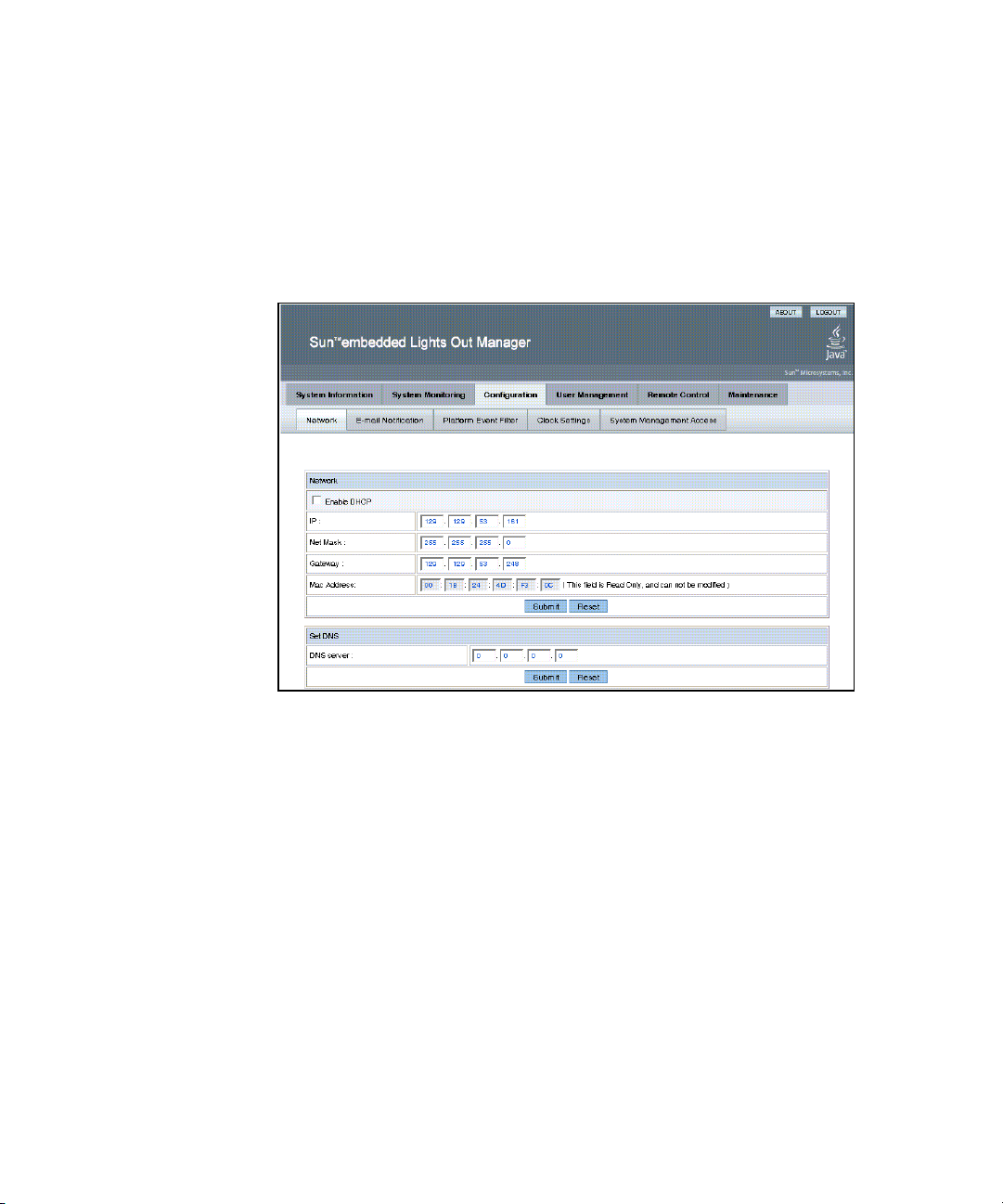
▼ To Configure the System
● From the main menu, click the Configuration tab.
The Configuration tabs appear (see
Network, E-mail Notification, Platform Event Filter, Clock Settings, and System
Management Access screens.
FIGURE 4-1 The Configuration Screen
FIGURE 4-1). You are now able to access the
Chapter 4 Configuring, Managing and Maintaining the Server Using the Web-Based Interface 29
Page 46

Configuring Network Settings
▼ To Configure the Network Settings
● From the Configure submenu, click the Network tab.
The Network configuration screen appears (see
enable or disable DHCP and set DNS. If you disable DHCP, you must manually
supply the IP address, the netmask, and the gateway.
FIGURE 4-1). Use this screen to
Configuring E-mail Notification
The E-mail Notification screen enables you to configure the e-mail recipients for any
ELOM generated events. The system allows you to designate up to 10 recipients. email notification is used in conjunction with Platform Event Filters (PEF). PEFs are
event traps that allow you to associate an action, or a set of actions, with the
occurrence of a specific event. One such action is mail notification. The Send Mail
action is enabled in the Platform Event Filter screen and configured in the E-mail
Notification screen.
▼ To Configure E-mail Notification
● From the Configuration submenu, click the E-mail Notification tab.
The Enable E-mail Notification screen appears. You must supply the name of the
SMTP server and the sender and designate the receiver e-mail addresses.
Configuring Platform Event Filters
The Platform Event Filter option allows you to configure actions for system
generated events. A system generated event is an alert that occurs when a threshold
for a system sensor is reached. For example, the system uses the sensors to monitor
various critical components. The components are most effective when operating
within a specific range. The limits of that range are defined as thresholds. All
components, such as fans, have an upper and lower critical threshold (see “To
Monitor Fans” on page 23). When either critical threshold is crossed the system
generates an alert. For example a fan failure would cause an alert for the lower
critical threshold. You can configure an event filter to trigger off the alert and
perform one or several actions. These actions include:
30 Sun Fire X4150 Server Embedded Lights Out Manager Administration Guide • September 2007
Page 47

■ Performing one of three power actions
■ Performing an NMI diagnostic interrupt
■ Sending alert to the SEL
■ Sending mail
An event is configured in two parts: the event (or alert) and the response or action to
be taken when that event occurs. You can configure up to six filters. You begin by
determining what sort of event you want to trap.
▼ To Configure a Platform Event Filter
1. From the Configuration submenu click Platform Event Filter tab.
The Platform Event Filter screen appears (see
divided into five sections:
■ Platform Event Filter
■ Trap Receiver Destination Address
■ PEF Action Global Control
■ Event Filter Configuration
■ Event Action Configuration
FIGURE 4-2). The PEF screen is
Chapter 4 Configuring, Managing and Maintaining the Server Using the Web-Based Interface 31
Page 48

FIGURE 4-2 The Platform Event Filter Screen
2. In the The Platform Event Filter section click the Enable PEF radio button.
To configure/create a filter, you must first enable PEF.
3. Type the address of the trap receiver in the Trap Receiver Destination Address
section.
4. Enable all actions that you would like to be available for your filters by
selecting the appropriate check box in the PEF Action Global Control section.
The actions are:
■ Enable Power Off Action
■ Enable Power Cycle Action
■ Enable Power Reset Action
■ Enable Diagnostic Interrupt Action
■ Enable Send Alert Action
■ Enable Send Mail Action
5. Select the sensor group for which you would like to filter alerts from the dropdown list in the Event Filter Configuration.
The options are:
■ ffh - All sensors
32 Sun Fire X4150 Server Embedded Lights Out Manager Administration Guide • September 2007
Page 49

■ 01h - Temperature
■ 02h - Voltage
■ 04h - Voltage
■ 07h - Processor
■ 0Ch - Memory
6. Select the action for the alerts by selecting the check boxes in the Event Action
Configuration section.
If you are selecting a power control action, select the action from the drop-down
list after selecting the Power Control check box.
In the example shown in
FIGURE 4-2, the system is configured to enable all
actions. A filter has been created to filter fan alerts. When an alert occurs, the
system will cycle power, send an alert to the SEL, and send mail to the addresses
listed in the E-mail Notification screen (see “Configuring E-mail Notification” on
page 30). You can configure up to six filters.
7. Click Submit to create the filter.
Configuring System Management Access
The System Management Access submenus allow you to set up the SSL certificate
and SNMP. The SSL configuration is used for creating certificates required in the
Certificate Signing Request (CSR). The certificate is required to enable encryption for
when you use HTTPS for secure web browser access. HTTPS requires a digitally
signed certificate to be installed at the applicant’s site. The SNMP screen allows the
configuration of SNMP settings, communities, and users.
▼ To access the System Management Access
Submenus
● From the Configuration submenu click the System Management Access tab.
The System Management Access submenu tabs appear.
Chapter 4 Configuring, Managing and Maintaining the Server Using the Web-Based Interface 33
Page 50

Configuring the SSL Certificate
▼ To Configure the SSL Certificate
1. From the System Management Access submenu, click the SSL Certificate tab.
The SSL Certificate screen appears.
2. Select either Certificate or CSR from the drop-down list.
3. Fill in the required fields in the SSL Configuration section.
4. Click Generate to create the certificate.
5. Click Upload to bring the certificate into view.
Note – If no certificate has yet been assigned, follow the directions below to
generate a new CSR.
6. Follow the onscreen directions, and fill in the fields using the example as a
guide.
The example in
TABLE 4-1 Example of Required SSL Information
TABLE 4-1 represents the kind of information required.
Common Name (CN): localhost.localdomain
Organization Unit (OU): Your Name
Organization (O): Your Company Name
Country Code (C): U.S.A. (drop-down list of countries)
Locality (L): Your Location
State (S): Your State
E-mail Address (E): youradmin@localhost.localdomain
7. Click Generate to create a new CSR.
Configuring SNMP
A series of screens allow you to set port, requests, and SNMP permission parameters
for the system you are logged in to.
34 Sun Fire X4150 Server Embedded Lights Out Manager Administration Guide • September 2007
Page 51

Note – The SNMP MIB file is located on the Tools and Drivers CD in the directory
/SNMP/mib/.
▼ To Configure SNMP
1. From the System Management submenu, click the SNMP tab.
The SNMP screen appears.
2. Select SNMP settings from the drop-down list, and then click Select.
The SNMP Settings screen appears.
3. Select the Set Request check box to set one or more SNMP variables.
This check box acts as a global override for the user and community read/write
permissions. For example, if you disable Set Requests, a member of the private
community accessing your Sun server or stand-alone system via the SNMP
interface cannot set sysContact despite having write permission.
4. Select the check box beside the preferred version of SNMP protocols to
override the delivered system default.
5. Click Submit to save the configuration, or click Reset to clear your entries.
▼ To Add an SNMP Community
1. In the SNMP screen, select SNMP Communities from the drop-down list and
click Select.
The SNMP Communities screen appears.
2. Select the radio button at the head of an unoccupied row.
3. Click Add to create a new community.
The Community Setting screen appears.
4. Type the name of the new community in the Community field.
5. Select a permission from the Permission drop-down list.
6. Click Submit to add the community.
Chapter 4 Configuring, Managing and Maintaining the Server Using the Web-Based Interface 35
Page 52

▼ To Delete an SNMP Community
1. In the SNMP screen, select SNMP Communities from the drop-down list, and
then click Select.
The SNMP Communities screen appears.
1. Select the radio button at the head of the row for the community that you want
to delete.
2. Click the Delete button to delete the community.
The system does not prompt for a confirmation.
▼ To Modify an SNMP Community
1. In the SNMP screen, select SNMP Communities from the drop-down list, and
then click Select.
The SNMP Communities screen appears.
2. To change permissions for an existing community, select the radio button at the
head of the row for the community you would like to modify.
3. Click Modify.
The displayed screen allows you to change file permissions for that community.
4. Select the permission from the Permission drop-down list.
The permission is either read-only (ro) or read/write (rw).
5. Click Submit to modify the community, or click Reset to clear your changes.
▼ To Add an SNMP User
1. In the SNMP screen, select SNMP User Settings from the drop-down list, and
then click Select.
The SNMP User Settings screen appears.
2. Select the radio button at the head of an unoccupied row.
3. Click Add to create a new user.
The User Setting screen appears.
4. Fill in the open fields for the new user in the User Setting screen.
The Authentication Protocol options are MD5 and SHA.
The Permission options are rw (read/write) and ro (read-only).
36 Sun Fire X4150 Server Embedded Lights Out Manager Administration Guide • September 2007
Page 53

5. Click Submit to create the new user.
▼ To Delete an SNMP User
1. In the SNMP screen, select SNMP User Settings from the drop-down list, and
then click Select.
The SNMP User Settings screen appears.
2. Select the radio button at the head of the row for the user that you want to
delete.
3. Click the Delete button to delete the user.
The system does not prompt for a confirmation
▼ To Edit an SNMP User
1. In the SNMP screen, select SNMP User Settings from the drop-down list, and
then click Select.
The SNMP User Settings screen appears. This screen allows you to add, delete,
and edit users.
2. Select the radio button at the head of the row for the user setting that you
would like to edit.
3. Click the Edit button in the same row.
The User Settings screen appears.
4. Edit the necessary user settings.
You cannot edit the user name. To change a user name, delete and re-create the
user with a different name.
5. Click Submit to save your changes.
Configuring Active Directory Service
The ADS Configuration screen enables you to browse and upload a certificate from
Active Directory Service (ADS) for a Microsoft Windows environment.
Administrators can simplify their tasks by monitoring multiple machines in one
node using ADS.
Chapter 4 Configuring, Managing and Maintaining the Server Using the Web-Based Interface 37
Page 54

▼ To Configure Active Directory Service
1. From the User Management submenu, click the ADS Configuration tab.
The ADS Configuration screen appears.
2. Enter the Primary, Secondary DNS and the Root Domain addresses.
3. If one is available, upload your certificate.
4. Click Submit, or click Reset to clear your changes.
Managing and Maintaining the System
The User Management, System Monitoring, Remote Control, Maintenance, and
System Information submenus enable you to manage and maintain server-related
functions. These functions are described in the following sections:
■ “Managing Users and Accounts” on page 38
■ “Managing the System Locator Indicator LED” on page 42
■ “Setting Power Control” on page 44
■ “Resetting the Service Processor” on page 44
■ “Updating the Firmware” on page 45
■ “Recovering from a Corrupt SP” on page 46
■ “Managing Session Timeout” on page 48
■ “Setting the Time” on page 49
Managing Users and Accounts
The User Management tab provides access to the User Account screen, which lists
current users by privilege and status, and enables the administrator to add, delete,
modify and enable/disable user accounts.
The ELOM supports up-to 10 user accounts. One of the user accounts is root, which
is set by default and cannot be removed. Therefore, you can configure 9 additional
accounts. Each user account consists of a user name, a password, and a permission.
Note – User permissions extend to both the web-based interface and the serial
connection methods.
38 Sun Fire X4150 Server Embedded Lights Out Manager Administration Guide • September 2007
Page 55

The permissions that a user can be assigned include:
■ Administrator – Enables read and write access to all ELOM software features,
functions, and commands.
■ Operator – Enables limited access to SP software features, functions, and
commands. Operators cannot change their assigned roles.
■ User – Enables a user to access the system without being able to add, modify, or
delete accounts.
■ Callback – Enables access to commands that set up the callback feature.
Note – If the SP password has been changed and then lost, a BIOS option exists to
reset the password back to the default changeme. See “Resetting the Service
Processor” on page 44. This method is not supported if you use a virtual CD-ROM.
▼ To Add a User
1. From the User Management submenu, click the User Account tab.
The User List screen appears.
2. Click any button labeled Add User.
The Manage User Account screen appears (see
If all 10 user account slots are configured, you must delete an existing user
account before you can add a new user account. See “To Delete a User Account”
on page 41.
FIGURE 4-3).
Chapter 4 Configuring, Managing and Maintaining the Server Using the Web-Based Interface 39
Page 56

FIGURE 4-3 The User Management Screen
3. Complete the following information.
a. Type a user name in the User Name field.
The user name must be at least 4 characters and no more than 20 characters.
User names are case-sensitive and must start with an alphabetical character.
You can use alphabetical characters, numerals, hyphens, and underscores. Do
not include spaces in user names.
b. Type a password in the Password field.
The password must be at least 8 characters and no more than 16 characters.
The password is case-sensitive. Use alphabetical, numeric, and special
characters for better security. You can use any character except a colon. Do not
include spaces in passwords.
c. Retype the password in the Confirm Password field to ensure that the
password is correct.
d. Select either Administrator, Operator, User, or Callback for the user
permission.
40 Sun Fire X4150 Server Embedded Lights Out Manager Administration Guide • September 2007
Page 57

e. When you finish entering the new user ’s information, click Add.
The User Accounts screen appears. The new user account and associated
information is displayed on the User Accounts screen.
▼ To Change a User Password or Privilege
1. From the User Management submenu, click the User Account tab.
The User List screen appears.
2. Click either the Change Password or Change Permission button for the user.
3. Change the password or privilege as needed.
4. After you have modified the user information, click Submit for your changes
to take effect, or click Reset to return to the previous settings.
A confirmation screen verifies that the user account was modified successfully.
▼ To Delete a User Account
1. From the User Management submenu, click the User Account tab.
The User List screen appears.
2. Click the Delete button for the user that you would like to delete.
You d o not receive a confirmation prompt.
▼ To Disable or Enable a User
Disabling a user makes the user account inactive. This might be preferable to
deleting the account.
1. From the User Management submenu, click the User Account tab.
The User List screen appears.
2. Click the Disable or Enable button for the appropriate user.
You d o not receive a confirmation prompt.
Chapter 4 Configuring, Managing and Maintaining the Server Using the Web-Based Interface 41
Page 58

Managing the System Locator Indicator LED
The System Locator Indicator LED is located on the front and rear panel of the
server. You can activate the Locator Indicator LED in the ELOM. By activating the
Locator Indicator LED for a particular server, you can identify that server from the
many other servers installed in a rack. You can manage the state of the System
Locator Indicator LED from the ELOM Maintenance screens.
▼ To Control the State of the System Indicator LED
1. From the main menu, click the System Monitoring tab.
The System Monitoring submenu tabs appear.
2. Click the Locator Indicator tab.
The System Indicator LED screen appears.
3. Select the appropriate radio button to either turn the LED on or turn it off.
4. Click Submit to change the state of the LED, or click Reset to cancel.
Managing the Front Panel and On-Board Fault LEDs
Your server is equipped with six fault LEDS. Four of the LEDs are on the front panel,
and two are located inside the server on the motherboard. Three of the front panel
LEDs are located on the right front side of the server front panel, the Top Open
(Check Fan Status) LED, the Power Supply (PS) LED, and the Overtemperature
Warning LED. These LEDs alert you to problems specific to a particular subsystem.
Use these LEDs in conjunction with the ELOM to troubleshoot down to the
component level.
The Fault LED (Service Required LED) is located on the left side of the server front
panel. This LED alerts you to an internal problem on the motherboard. Use the Fault
LED in conjunction with the two internal on-board fault LEDs, the CPU LED and the
DIMM LED to troubleshoot issues related to a specific CPU or DIMM.
You can monitor and manage the state of the Fault LEDs from the ELOM
Maintenance screens. For more information about using the fault LEDs to
troubleshoot server problems, see the Sun Fire X4150 Server Service Manual.
42 Sun Fire X4150 Server Embedded Lights Out Manager Administration Guide • September 2007
Page 59

▼ To View the State of the Fault LEDs
1. In the main menu, click the System Monitoring tab.
The System Monitoring submenu tabs appear.
2. Click the Fault LED submenu tab.
The Fault LED Control screen appears (see
FIGURE 4-4 The Fault LED Screen
FIGURE 4-4).
The Fault LED screen is divided into three sections, the Fault LED Control
section, the Front Panel Fault LED Control, and the On-Board Fault LED Control.
These sections allow you to monitor and change the status of each LED. If the
current status of an LED is On, then you will have the option to turn it Off.
Otherwise, the LED status is shown as Off. For example in
FIGURE 4-4, the front
panel Fault LED, the Overtemperature Warning LED and the internal on-board
CPU LED and DIMM LED are On.
▼ To Turn the Fault LEDs Off
1. Select the appropriate radio button for the fault LED that you would like to
turn off.
2. Click the appropriate Submit button for the particular section to turn the LED
off.
Chapter 4 Configuring, Managing and Maintaining the Server Using the Web-Based Interface 43
Page 60

Setting Power Control
You can control power to the server you are logged in to by using the Remote Power
Control submenu screen to set the power control action.
▼ To Set Power Control
1. From the Remote Control tab of the Embedded Lights Out Manager software
screen, choose Remote Power Control.
The Power Control screen appears showing a drop-down list of various poweroff and restart options: Force Power Off, Reset, Graceful Shutdown, Boot Option:
BIOS Setup, Boot Option: PC Check, and NMI.
2. Select power option you want and click Save.
For example, select Boot Option: BIOS Setup to reboot the system and enter the
BIOS.
3. When you have made your changes, click Submit to save the changes, or click
Reset to clear the changes.
Resetting the Service Processor
The baseboard management controller holds the original default settings of the
service processor. In the event of system lock-up or panic you can reset the SP to its
original state.
▼ To Reset the Service Processor
1. From the main menu click the Maintenance tab.
The Maintenance submenus appear.
2. Click the Reset SP submenu tab.
The Reset SP screen appears.
Note – Resetting the SP is a hard reset. Because you are logged in to the web-based
interface when the SP is reset, the interface will become inactive.
44 Sun Fire X4150 Server Embedded Lights Out Manager Administration Guide • September 2007
Page 61

3. Click Reset SP button.
The following message appears:
Please wait for SP reset then reconnect.
Updating the Firmware
There are multiple ways to update the SP firmware.
■ Use the Tools and Drivers CD.
1. Power on the system and boot the system using the Tools and Drivers CD.
2. Five menu options appear. To update the firmware, select one of the following
two options:
■ Flash System BIOS/Service Processor Firmware—Clear BIOS CMOS and load
default settings (recommended).
■ Flash the System BIOS/Service Processor Firmware—Preserve BIOS CMOS
settings (advanced use only).
Note – Use the second option only if you have customized BIOS settings and would
like to retain these settings. This option might require user intervention during the
reboot.
■ Use TftpUpdate through the CLI. See “To Update the Firmware” on page 86.
■ Use CPLDUpdate through the CLI. See to “To Update the Firmware” on
page 86.
■ Use a web browser to update firmware. See the next section, “Updating the
Firmware Using a Web Browser” on page 45.
Updating the Firmware Using a Web Browser
This section explains how to update firmware to a remote server. There are two
options for updating firmware.
1. Clear CMOS (default)
2. Preserve CMOS
If the system BIOS has not been customized, select option #1: Clear CMOS. If the
system BIOS has been customized, select option #2: Preserve CMOS.
Chapter 4 Configuring, Managing and Maintaining the Server Using the Web-Based Interface 45
Page 62

Note – Selecting option #2 might require user interaction during the reboot.
▼ To Update the Firmware Using a Web Browser
Note – The system must be powered off for you to perform an update. If the server
is powered on, the SP warns the user to power off before continuing. The option to
update firmware will not be available if the server is powered on. For information
about how to power-off the server, see “Setting Power Control” on page 44.
1. From the main menu, select the Maintenance tab.
The Maintenance submenu tabs appear.
2. Click the Firmware Update tab.
The Firmware Update screen appears.
3. Select the firmware file or CPLD file to update.
These files are located on the Tools and Drivers CD in the Remote_Firmware
directory.
4. Choose whether to preserve the system BIOS CMOS and load optimized
defaults.
5. Firmware will perform a check and ask the user to confirm the update by
displaying current and proposed firmware revisions.
6. When the update is finished, after approximately five minutes, the SP resets
and you are logged out.
Recovering from a Corrupt SP
Should the SP (service processor) software become corrupted, you can reinstall the
default image from the CD. You need a bootable USB flash device and a jumper cap.
Note – The server has a a jumper cap installed on the motherboard for this purpose.
It is next to the AST 2000 chip.
46 Sun Fire X4150 Server Embedded Lights Out Manager Administration Guide • September 2007
Page 63

▼ To Recover From a Corrupt SP
1. Copy all SP files from the Tools and Drivers CD to a USB flash device.
The SP files are located in the BMCrecovery directory, on the Tools and Drivers
CD. They consist of:
■ SOCFLASH.EXE
■ DOS4GW
■ BMC Binary (SP Binary file)
2. Remove AC power from system to be flashed.
Note – Do not attempt to flash the system while it is still powered on. An
unrecoverable error might occur.
3. Remove the server’s top cover.
4. Using a jumper cap, short the pins at jumper JP20 on the server motherboard.
JP20 is located toward the rear of the board. See the Sun Fire X4150 Server Service
Manual for the precise location.
5. Insert the bootable flash drive into the USB port.
6. Connect AC power and power on the system.
a. A message appears stating that the BMC was not found.
The system takes up to three minutes to boot.
b. Press F2 to enter system BIOS and verify that the Flash device is in the boot
order.
7. Once the flash device is booted, run the following command:
socflash.exe SP binary backup file
For example:
socflash.exe s92v092.bin backup.bin
8. After a successful flash, remove the AC power and jumper, and leave the
system powered off for up to 30 seconds.
9. Power on the system.
10. Confirm that the SP is listed in the BIOS settings under Server/AST2000 LAN
Configuration.
Chapter 4 Configuring, Managing and Maintaining the Server Using the Web-Based Interface 47
Page 64

Managing Session Timeout
The session timeout is an inactivity timer. If an open session enters a state of
inactivity that exceeds the preset timer, the system closes (logs out) the session. This
function prevents unauthorized access to the system by providing an automated
logout function. The session timeout is enabled by default.
▼ To Set the Session Timeout
1. From the main menu, click the System Information tab.
The Versions, Session Time-Out, and Components submenu tabs appear.
2. Select the Session Time-Out tab.
The Session Time-Out screen appears.
3. Click the Enable Timeout radio button.
4. Select a session time from the Session Time drop-down list.
The options are 15 minutes (default), 30 minutes, 1-hour, and 2 hours.
5. Click the Submit button to set the session timeout.
▼ To Disable the Session Timeout
1. From the main menu, click the System Information tab.
The Versions, Session Time-Out, and Components submenu tabs appear.
2. Select the Session Time-Out tab.
The Session Time-Out screen appears.
3. Click the Disable Time-Out radio button.
4. Click the Submit button to disable the session timeout.
48 Sun Fire X4150 Server Embedded Lights Out Manager Administration Guide • September 2007
Page 65

Setting the Time
▼ To Set the Time
1. From the Configuration submenu, click the Set Time tab.
The Set Time screen appears. Use the radio buttons to either manually input the
date and time, or to use an NTP server. For the latter, you will have to input the
IP address of the server.
Chapter 4 Configuring, Managing and Maintaining the Server Using the Web-Based Interface 49
Page 66

50 Sun Fire X4150 Server Embedded Lights Out Manager Administration Guide • September 2007
Page 67

CHAPTER
5
Using the Remote Console Application
This chapter describes how to use the remote console application. It includes the
following sections:
■ “Accessing the Remote Console” on page 51
■ “Starting the Remote Console Application” on page 54
■ “Redirecting Keyboard, Video, Mouse, or Storage Devices” on page 56
■ “Installing an Operating System on a Remote Server” on page 58
■ “Other Remote Options” on page 59
Accessing the Remote Console
The remote console application, which you access via a web browser, enables you to
control your server’s operating system remotely using the screen, mouse, and
keyboard, and to redirect local CD and diskette drives as if they were connected
directly to the server.
Requirements
A compatible web browser and a minimum of JRE™ 1.6.0 are required to operate the
remote console application. See
TABLE 5-1.
51
Page 68

Note – You do not need to install any OS-specific drivers or helper applications on
client systems to run the remote console application.
TABLE 5-1 Client Installation Requirements
Client OS
Microsoft Windows XP Pro JRE 1.6 (Java 6.0 or later) Internet Explorer 6.0 and
Red Hat Linux 4.0 or later
Desktop and Workstation
Editions
Solaris 9 JRE 1.6 (Java 6.0 or later) Mozilla 1.7.5
Solaris 10 JRE 1.6 (Java 6.0 or later) Mozilla 1.7.5
SUSE Linux 9.2 JRE 1.6 (Java 6.0 or later) Mozilla 1.7.5
Java Runtime Environment Including
Java Web Start Web Browsers
later
Mozilla 1.7.5 or later
Mozilla Firefox 1.0
JRE 1.6 (Java 6.0 or later) Mozilla 1.7.5 or later
Mozilla Firefox 1.0
Note – You can download the JRE 1.6 at http://java.sun.com.
Note – To start the remote console successfully, pop-ups must be allowed on the
browser. With some browsers you can do this by pressing and holding the Control
key when launching the remote console session.
CD and Diskette Redirection Operational Model
When you redirect the local client CD drive or diskette drive to a remote host server,
the following rules apply:
■ In all cases, the CD drive and diskette drive appear to be plugged in to the host.
■ If you do not redirect them, the host acts as if there is no medium unless there is
a CD in the host CD drive. If there is a CD in the host CD drive, the host accesses
it normally.
52 Sun Fire X4150 Server Embedded Lights Out Manager Administration Guide • September 2007
Page 69

The information in TABLE 5-2 describes different case scenarios in which the remote
console application and CD drive and diskette drive redirection operate.
TABLE 5-2 Remote Console Operation With DVD Drive and Diskette Drive
Case Status DVD Seen by Host Diskette Seen by Host
1 Remote console application not
started or remote console started
but DVD/diskette redirection not
started.
2 Remote console application
started with no medium present
in the drive.
3 Remote console application
started with no medium, then
medium is inserted.
4 Remote console application
started with medium inserted.
5 Remote console application
started with medium present,
then medium is removed.
6 Remote console application
started with image redirection.
7 Remote console application
started with image, but
redirection is stopped (which is
the only way to stop ISO
redirection).
8 Network failure. The software has a keep alive
9 Client crashes. Same as 8. Same as 8.
DVD device present. No medium
indication is sent to the host from
the ELOM when the hosts asks.
Diskette device present. No
medium indication is sent to the
host from the ELOM when the
host asks.
DVD device present. Whenever
the host asks, which may be
automatic or when you access the
device on the host, the remote
client sends a status message. In
this case since there is no
medium, the status is no
Diskette device present.
Whenever the host asks (for
example, you double-click a
drive), the remote client sends a
status message. In this case since
there is no medium, the status is
no medium.
medium.
DVD device present. Whenever
the hosts asks (automatic or
manual), the remote client sends
a status message as medium
present and also indicates the
medium change.
Diskette device present.
Whenever the host asks
(manual), the remote client sends
a status message as medium
present and also indicates the
medium change.
Same as 3. Same as 3.
Next command from the host
gets a status message indicating
medium not present.
Next command from the host
gets a status message indicating
medium not present.
Same as 3. Same as 3.
Driver knows DVD redirection
stopped so it sends a medium
absent status on the next host
query.
Driver knows DVD redirection
stopped so it sends a medium
absent status on the next diskette
query.
The software has a keep alive
mechanism. The software detects
keep alive failure since there is
no communication and closes the
socket, assuming the client is
unresponsive. Driver sends a no
medium status to the host.
mechanism. The software detects
and unresponsive client, closes
the socket, and indicates to the
driver that the remote connection
went away. Driver sends a no
medium status to the host.
Chapter 5 Using the Remote Console Application 53
Page 70

Starting the Remote Console Application
Use this procedure to start the remote console application from a web browser. You
might be presented with a series of questions. In each case, select Run.
Note – Each new ELOM system is delivered with DHCP set as the default. If an IP
address is not found within 5 seconds, the system retries three times to find a DHCP
server. It it is still unsuccessful, the SP will default to the IP address 192.168.xxx.xxx
where xxx.xxx is based upon the last two fields of the SP MAC address, to allow
instant web access.
▼ To Start the Remote Console Application
1. Open your web browser.
2. In the address bar, enter the IP address of the SP.
The login screen appears.
3. Type an administrator user name and password.
Or use the default preconfigured account:
Username: root
Password: changeme
4. Click Login.
The main menu screen appears.
5. Click the Remote Control tab, and select Redirection.
The screen displays a Launch Redirection button.
6. Click Launch Redirection.
A screen identifies your current host name, IP address, and user name. The
Launch button opens the remote console.
7. Click Launch.
Note – For systems using Firefox and Mozilla web browsers, the required version of
JRE must be at least version 1.6 or later.
54 Sun Fire X4150 Server Embedded Lights Out Manager Administration Guide • September 2007
Page 71

The web browser downloads the embedded remote control application
automatically, and the Remote Console screen appears.
If the remote console does not appear, it might be blocked by web browser security
controls. Reduce security configuration to allow the remote console to appear.
Note – To start the remote console successfully, pop-ups must be allowed on the
browser. With some browsers you can do this by pressing and holding the Control
key when launching the remote console session.
Changing the format of the screen is described in the following section, “To Set
Parameters for the Remote Console” on page 55.
Setting Parameters for the Remote Console
This section explains how to define the quality of video, the size of the screen, and
set hot keys for the remote console application.
▼ To Set Parameters for the Remote Console
1. From the Remote Control submenu, select Hotkey Setup.
The User Profile screen appears. The User Profile screen allows you to set up
separate video, KVM, and hot key settings for each user. The subsequent window
displays a version of the screen output. This requires a Java Webstart application
to be launched.
a. The first time this application is launched you must respond to accept
various security questions before the application is installed and operates
correctly.
b. Right-click to display the remote console as a full screen.
By default, the remote console will synchronize both mouse cursors, and
display only one mouse cursor within the remote console screen.
When the mouse cursor leaves the screen, the local cursor takes over and the
other mouse cursor remains in the remote console screen.
You can enable user modes in the setup of the web-based interface or in the
remote console screen.
Chapter 5 Using the Remote Console Application 55
Page 72

2. When the login is successful, the remote console screen appears.
The remote console application starts with the video and keyboard enabled by
default. In most cases, you need only enable the mouse redirection. You can now
use the remote console application to start your server’s operating system.
Note – For detailed instructions on how to enable and disable I/O and storage
devices (CD-ROM and diskette drives), see “Redirecting Keyboard, Video, Mouse, or
Storage Devices” on page 56.
Redirecting Keyboard, Video, Mouse, or Storage Devices
The remote console application supports the redirection of the following types of
devices:
■ Video quality display – the server’s video output is automatically displayed on
the local console screen.
■ Hot key – enable a single key to mimic a series of keystrokes.
■ Keyboard and mouse devices – Standard keyboards, mouse, and other pointing
devices.
■ Keyboard redirection is enabled by default.
■ Mouse redirection must be enabled manually.
■ Storage devices – CD/DVD drives, Flash, DVD-ROM or diskette disk drives, hard
drives, or NFS.
▼ To Redirect Keyboard and Mouse Devices
Use the following procedure to redirect your local workstation or laptop keyboard
and mouse to a remote Sun Fire X4150 server.
1. Start the remote console application as described in “Starting the Remote
Console Application” on page 54.
2. From the Remote Control submenu, select the Hotkey Setup tab.
The Control Mode section of the Hotkey Setup screen enables mouse redirection.
3. Select Hardware Cursor to enable a variety of cursor movements.
56 Sun Fire X4150 Server Embedded Lights Out Manager Administration Guide • September 2007
Page 73

Note – For the mouse to work correctly, you might have to change the mouse mode.
Click the double mouse cursor on the navigation bar to toggle between local and
remote mouse cursor movement. Keyboard redirection is selected by default.
FIGURE 5-1 Keyboard, Video, and Mouse Selections
You can click Submit to enable your options after each choice to observe the
consequences, or continue directly to Step 4.
4. When you have completed your selections, click Submit to enable your
options.
▼ To Redirect Storage Devices
Use the following procedure to enable a storage device attached to your local
workstation or laptop to serve as a storage device for a server. You can use this
option to install software from a local CD/DVD drive to multiple remote servers.
You can also redirect a CD image file or a diskette image file stored on your hard
drive.
1. Start the remote console application as described in “Starting the Remote
Console Application” on page 54.
The Remote Console screen appears.
2. Select Storage from the drop-down list, and click Mount Device.
This enables the corresponding local storage device to connect to the remote
server as though it were a storage device attached directly to that remote server.
3. Select a source device from the drop-down list.
Chapter 5 Using the Remote Console Application 57
Page 74

■ To store a selection to a real CD-ROM device, select from the Drive Name
drop-down list.
■ To store a CD image file or a diskette image file to your hard drive, select ISO
file from the Source Device drop-down list.
Note – You cannot select two CD-ROM devices or two diskette devices. For
example, you cannot select CD-ROM and CD-ROM image. Use the web browser to
navigate to the corresponding file, then click Submit.
Installing an Operating System on a Remote Server
This method includes using a CD or DVD drive or image of the operating system on
a remote networked system to install the operating system, for example, onto the
Sun Fire X4150 server.
Requirements for Remote KMVS Over IP installation include:
■ Remote system connected to the network
■ CD/DVD drive connected to the remote system
■ Media for installing the operating system of your choice
■ SP of the server set up as instructed in the Sun Fire X4150 Server Installation Guide.
▼ To Install an OS on a Remote Server Using a
Virtual CD-ROM
Note – Disable the timeout function when installing remotely from the virtual CD-
ROM.
1. On your laptop or local terminal, open a web browser, and enter the IP address
of the Sun Fire X4150 server service processor for the target system.
This is the Sun Fire X4150 server on which you want to install the operating
system.
2. Type the user name and password in the login screen.
58 Sun Fire X4150 Server Embedded Lights Out Manager Administration Guide • September 2007
Page 75

3. From the Remote Control submenu, click the Redirection tab.
4. Click the Launch Redirection button to open a remote console screen.
5. Insert the operating system CD/DVD to be installed on the Sun Fire X4150
server into your laptop or local CD/DVD drive.
6. In the remote console screen, choose Storage –>Mount devices.
The Device Configuration screens appears.
7. Under Storage 1, in the drop-down list, select the local CD/DVD that you will
be using for the installation.
8. Click Submit.
9. Reboot the server.
The system will add the virtual CD-ROM to the boot order, and boot from it.
Other Remote Options
Command-line options that are available to address many of these tasks include
IPMI tools (Chapter 6), CLI (Chapter 7), and SSH (Secure Shell).
Chapter 5 Using the Remote Console Application 59
Page 76

60 Sun Fire X4150 Server Embedded Lights Out Manager Administration Guide • September 2007
Page 77

CHAPTER
6
Using IPMI
This chapter describes the Intelligent Platform Management Interface (IPMI)
functionality and lists the supported IPMI commands. It includes the following
sections:
■ “About IPMI” on page 61.
■ “Supported IPMI 2.0 Commands” on page 63.
About IPMI
The Intelligent Platform Management Interface (IPMI) is an open-standard hardware
management interface specification that defines a specific way for embedded
management subsystems to communicate. IPMI information is exchanged through
the service processor (SP), an IPMI-compliant hardware component. Using low-level
hardware intelligence instead of the operating system has two main benefits: First,
this configuration allows for out-of-band server management, and second, the
operating system is not burdened with transporting system status data.
You can manage your server with the IPMI v.1.5/2.0 on your server or stand-alone
server, which runs a daemon to do the following:
■ Support low pin count (LPC) host interface in two modes:
■ KCS Mode (3 channels)
■ BT Mode (1 channel with 32 bytes of FIFO)
■ Support dedicated NIC or shared lights out management (LOM)
■ Support Serial-On-LAN (SOL)
■ Customize FRU/Sensor Data Record data (firmware independent)
■ Provide KVM over IP (remote access to the server)
■ Enable the user interface (UI) for hot key definitions (for example Ctrl-Alt-Del)
61
Page 78

■ Provide full screen display switch
■ Set dynamic video scaling (4x4 Video Scalar)
Your Sun Fire X4150 server is IPMI v2.0 compliant. You can access IPMI functionality
through the command line with the IPMItool utility either in-band or out-of-band.
Additionally, you can generate an IPMI-specific trap from the web interface or
manage the server’s IPMI functions from any external management solution that is
IPMI v1.81 or v2.0 compliant. For more information about the IPMI v2.0
specification, go to:
http://www.intel.com/design/servers/ipmi/spec.htm#spec2
IPMItool
IPMItool is a simple command-line interface that is useful for managing IPMIenabled devices. You can use this utility to perform IPMI functions with a kernel
device driver or over a LAN interface. IPMItool enables you to manage system fieldreplaceable units (FRUs), monitor system health, and monitor and manage system
environmentals, independent of the operating system.
Download this tool from http://ipmitool.sourceforge.net/, or locate
IPMItool and its related documentation on your server Tools and Drivers CD.
When IPMItool is installed, it includes a man page. To view it, enter:
man ipmitool
If your client machine has a default installation of Solaris 10, you can find a
preinstalled version of IPMItool in the following directory:/usr/sfw/bin. The
binary file is called ipmitool.
Sensors
Your server includes a number of IPMI-compliant sensors. Some sensors measure
voltages, and temperature ranges, and others are capable of monitoring switches,
such as the chassis interlocks, which detect whether the chassis cover is open or
shut. For a complete list of sensors, see your platform supplement. To obtain sensor
information on specific sensors, enter the following command:
ipmitool -H ipaddressof the SP -U username -P password [sensor|sdr]
The sensors can activate system fault lights, and register events in the system event
log (SEL). To see the system event log from the IPMItool, at the prompt, enter the
following command:
62 Sun Fire X4150 Server Embedded Lights Out Manager Administration Guide • September 2007
Page 79

ipmitool -H ipaddress of the SP -U root -P password sel list
Depending on where IPMItool is installed from, the -P option might be missing. In
such a case, do not type the -P in the previous command, and enter the password
when prompted.
Supported IPMI 2.0 Commands
TABLE 6-2 lists the supported IPMI 2.0 commands.
For details on individual commands, see the IPMI Intelligent Platform Management
Interface Design Specification, v2.0. A copy is available at:
http://www.intel.com/design/servers/ipmi/spec.htm
TABLE 6-1 Supported IPMI 2.0 Commands
Commands Description
raw Send a RAW IPMI request and print response
i2c Send an I2C Master Write-Read command and print response
lan Configure LAN channels
chassis Get chassis status and set power state
power Shortcut to chassis power commands
event Send predefined events to MC
mc Management Controller status and global enables
sdr Print Sensor Data Repository entries and readings
sensor Print detailed sensor information
fru Print built-in FRU and scan SDR for FRU locators
sel Print system event log (SEL)
pef Configure platform event filtering (PEF)
sol Configure and connect IPMIv2.0 Serial-over-LAN
tsol Configure and connect with Tyan IPMIv1.5 Serial-over-LAN
isol Configure IPMIv1.5 Serial-over-LAN
user Configure Management Controller users
channel Configure Management Controller channels
session Print session information
Chapter 6 Using IPMI 63
Page 80

TABLE 6-1 Supported IPMI 2.0 Commands (Continued)
Commands Description
sunoem OEM commands for Sun servers
kontronoem OEM commands for Kontron devices
picmg
Run a PICMG/ACTA extended cmd
fwum Update IPMC using Kontron OEM Firmware Update Manager
exec Run list of commands from file
set
TABLE 6-2 Supported IPMI 2.0 Commands
Supported IPMI 2.0 Commands
General Commands
Get Device ID
Cold Reset
Get Self Test Results
Set/Get ACPI Power State
Reset/Set/Get Watchdog Timer
Set/Get BMC Global Enables
Clear/Get Message Flags
Enable Message Channel Receive
Get/Send Message
Read Event Message Buffer
Get Channel Authentication Capabilities
Get Session Challenge
Activate/Close Session
Set Session Privilege Level
Get Session Info
Set/Get Channel Access
Get Channel Info
Set/Get User Access
Set/Get User Name
Set runtime variable for shell and exec
64 Sun Fire X4150 Server Embedded Lights Out Manager Administration Guide • September 2007
Page 81

TABLE 6-2 Supported IPMI 2.0 Commands (Continued)
Supported IPMI 2.0 Commands (Continued)
Set User Password
Master Write-Read
Set/Get System Boot Options
Set/Get Event Receiver IPMI
System Interface Support
KCS
BT
Serial Over LAN
RCMP
• Multiple Payloads
• Enhanced Authentication
• Encryption
PEF and Alerting Commands
Get PEF Capabilities
Arm PEF Postpone Timer
Set/Get PEF Configuration Parameters
Set/Get Last Processed Event ID
Alert Immediate
PET Acknowledge
Sensor Device Commands
Get Sensor Reading Factors
Set/Get Sensor Hysteresis
Set/Get Sensor Threshold
Set/Get Sensor Event Enable
Get Sensor Reading
FRU Device Commands
Get FRU Inventory Area Info
Chapter 6 Using IPMI 65
Page 82

TABLE 6-2 Supported IPMI 2.0 Commands (Continued)
Supported IPMI 2.0 Commands (Continued)
Read/Write FRU Data SDR Device
Get SDR Repository Info
Get SDR Repository Allocation
Reserve SDR Repository
Get/Add SDR
Clear SDR Repository
Get SDR Repository Time
Run Initialization Agent
SEL Device Commands
Get SEL Info
Get SEL Allocation Info
Reserve SEL
Get/Add SEL Entry
Clear SEL
Set/Get SEL Time
LAN Device Commands
Get LAN Configuration Parameters
Serial/Modem Device Commands
Set/Get Serial Modem Configuration
Set Serial Modem MUX
Get TAP Response Codes
Serial/Modem Connection Active
Callback
Set/Get User Callback Options
Event Commands
Get Event Count
66 Sun Fire X4150 Server Embedded Lights Out Manager Administration Guide • September 2007
Page 83

TABLE 6-2 Supported IPMI 2.0 Commands (Continued)
Supported IPMI 2.0 Commands (Continued)
Set/Get Event Destination
Set/Get Event Reception State
Send ICMB Event Message
Chapter 6 Using IPMI 67
Page 84

68 Sun Fire X4150 Server Embedded Lights Out Manager Administration Guide • September 2007
Page 85

CHAPTER
7
Using the Command-Line Interface
This chapter describes how to use the Embedded Lights Out Manager command-line
interface (CLI). The sections include:
■ “Logging In to the CLI” on page 69.
■ “Command Syntax” on page 70.
■ “Managing the Host” on page 72.
■ “Managing ELOM Network Settings” on page 74.
■ “Managing Local User Accounts With the CLI” on page 75.
■ “Managing Alerts” on page 78.
■ “Displaying Version Information” on page 85.
■ “Updating the Firmware” on page 86.
Logging In to the CLI
You can access the command-line interface through the serial port or over the
Ethernet.
■ Serial port – The serial port provides access to the CLI and to the system console.
IPMI terminal mode and PPP mode are not available on the serial port. For
information about logging in to the CLI using the serial port, see “Connecting
Using a Serial Connection” on page 6.
■ SSH –You can connect to the CLI using an Ethernet connection. Secure Shell
connections (SSC) are enabled by default. For information about logging in to the
CLI using an Ethernet connection, see “Connecting Using Ethernet” on page 7.
The Sun Fire X4150 server ELOM supports a maximum of 10 active sessions,
including serial, SSH, and web interface sessions. Telnet connections to the ELOM
are not supported.
69
Page 86

Note – If you have changed the serial redirection output in the system BIOS from SP
to SYSTEM, the system output is displayed on the serial connection. To view the SP
output on the serial connection, change the system BIOS back to the default BMC.
Command Syntax
The CLI architecture is based on a hierarchical namespace, which is a predefined tree
that contains every managed object in the system. This namespace defines the
targets for each command verb.
The Embedded Lights Out Manager (ELOM) software includes the /SP and /SYS
namespaces.
The /SP namespace manages the ELOM. The children of this namespace are /user,
/network, /clock, /AgentInfo, /TftpUpdate, and /CPLDUpdate, which allow you
to use this space to manage users, clock settings, and other issues.
The /SYS namespace monitors the ELOM. The children of this namespace include
/BoardInfo, /ProductInfo, /ChassisInfo, /CtrlInfo, /CPU, /MemModule, /Fan,
/Temperature, and /Voltage
The CLI provides two privilege levels: Administrator and User. Administrators have
full access to ELOM functionality, and users have read-only access to information.
Note – The default user, root, has administrator privileges. For information about
how to create a user account with user privileges, see “Adding a User Account
Using the CLI” on page 76.
CLI commands are case-sensitive.
Syntax
The syntax of a command is verb options target properties.
70 Sun Fire X4150 Server Embedded Lights Out Manager Administration Guide • September 2007
Page 87

Command Verbs
TABLE 7-1 describes the CLI command verbs.
TABLE 7-1 CLI Command Verbs
Command Description
cd Navigates the object namespace.
create Sets up an object in the namespace.
delete Removes an object from the namespace.
exit Terminates a session to the CLI.
help Displays Help information about commands and targets.
losd
reset Resets the target’s state.
set Sets target properties to the specified value.
show Displays information about targets and properties.
start Starts the target.
stop Stops the target.
version Displays the version of ELOM firmware that is running.
Options
The CLI supports the following options. Not all options are supported for all
commands. See a specific command section for the options that are valid with that
command. The -help and -examine options can be used with any command.
TABLE 7-2 CLI Options
Option Long Form Shor t Form Description
-default Causes the verb to perform only its default functions.
-destination Specifies the destination for data.
-display -d Shows the data you want to display.
-examine -x Examines the command but does not execute it.
-force -f Causes an immediate action instead of an orderly
shutdown.
-help -h Displays Help information.
Chapter 7 Using the Command-Line Interface 71
Page 88

TABLE 7-2 CLI Options (Continued)
Option Long Form Shor t Form Description
-keep -k Establishes a holding time for command job ID and
status.
-level -l Executes the command for the current target and all
targets contained through the level specified.
-output -o Specifies the content and form of command output.
-resetstate Indicates to what target-specific state to reset the
target.
-script Skips warnings or prompts normally associated with
the command.
-source Indicates the location of a source image.
Targets
Every object in your namespace is a target. Not all targets are supported for all
commands. Each command section lists the valid targets for that command.
Properties
Properties are the configurable attributes specific to each object. An object can have
one or more properties. Each command section lists the valid properties for each
target.
Managing the Host
You can use the ELOM to change the host’s state and to access the host console.
Managing the Host State
■ To power on the host, enter one of the following commands:
set /SYS/CtrlInfo PowerCtrl=on
-or-
start SYS
72 Sun Fire X4150 Server Embedded Lights Out Manager Administration Guide • September 2007
Page 89

■ To power off the host gracefully, enter the following command:
set /SYS/CtrlInfo PowerCtrl=graceful_off
■ To power off the host, enter one of the following commands:
set /SYS/CtrlInfo PowerCtrl=off
-or-
stop SYS
■ To reset the host, enter one of the following commands:
set /SYS/CtrlInfo PowerCtrl=reset
-or-
reset SYS
■ To reboot and enter the BIOS automatically, enter the following command:
set /SYS/CtrlInfo PowerCtrl=BIOSSetup
■ To reboot and enter Pc-Check diagnostic automatically, enter the following
command:
set /SYS/CtrlInfo PowerCtrl=PCCheck_enable
Managing the Host Console
To start a session to the server console, enter this command:
start /SP/AgentInfo/Console
To revert to CLI once the console has been started, press Esc-Shift-9 keys.
To terminate a server console session started by another user, enter this command:
stop /SP/AgentInfo/Console
Viewing Host Sensors
Host systems are equipped with sensors that monitor the state of critical
components. For example, they record things like temperatures, voltages, and fan
speeds. The show command can be used to show the state of the critical
components. Use the command:
show /SYS/CPU/component
component The particular critical component.
For example, the following command shows the state of CPU 0:
Chapter 7 Using the Command-Line Interface 73
Page 90

show /SYS/CPU/CPU0
For more information about sensors, including how to view them using a web
browser, see “Monitoring the System Sensors” on page 19.
Managing ELOM Network Settings
You can display or configure the ELOM network settings from the CLI.
▼ To Display Network Settings
Enter the following command to display or set network settings:
show /SP/network (This will display all network settings.)
▼ To Configure Network Settings
Use the set command to change properties and values for network settings.
Note – Ensure that the same IP address is always assigned to an ELOM by either
assigning a static IP address to your ELOM after initial setup, or configuring your
DHCP server to always assign the same IP address to an ELOM. This enables the
ELOM to be easily located on the network.
74 Sun Fire X4150 Server Embedded Lights Out Manager Administration Guide • September 2007
Page 91

Targets, Properties, and Values
These targets, properties, and values are valid for ELOM network settings.
TABLE 7-3
Target Property Value Default
/SP/network IpAddress
IPSource
Gateway
Netmask
ipaddress|none
static/dhcp
ipaddress|none
ipdotteddecimal
192.168. last 2 digits of MAC address
enabled (only if DHCP not found)
dhcp
None
255.255.255.0
Examples
To change the IP address for the ELOM, Enter:
Note – Changing the IP address will disconnect your active session if you are
connected to the ELOM via a network.
Syntax
set /SP/network IPAddress=n.n.n.n
set /SP/network Gateway=n.n.n.n
set /SP/network DNS=n.n.n.n
set /SP/network IPSource=[static|dhcp]
Managing Local User Accounts With the CLI
This section describes how to add, modify, and delete user accounts using the CLI.
The ELOM supports up to 10 user accounts. One of those, root, is set by default and
cannot be removed. Therefore, you can configure 9 additional accounts.
Each user account consists of a user name, a password, and a permission.
The permisisons include:
Chapter 7 Using the Command-Line Interface 75
Page 92

■ Administrator – Enables read and write access to all ELOM software features,
functions, and commands.
■ Operator – Enables limited access to SP software features, functions, and
commands. Operators cannot change their assigned roles.
■ User – Enables a user to access the system without being able to add, modify, or
delete accounts.
■ Callback – Enables access to commands that set up the callback feature.
The syntax is:
set username Permission=[administrator|operator|user]
Adding a User Account Using the CLI
▼ To Add a User Account Using the CLI
● Enter the following command:
create /SP/users/username
You are prompted for a password.
The username must be 4-20 characters long, and passwords must be a minimum
of eight characters long.
To Delete a User Account Using the CLI
● Enter the following command:
delete /SP/users/username
▼ To Display User Accounts Using the CLI
● Enter the following command:
show /SP/users
76 Sun Fire X4150 Server Embedded Lights Out Manager Administration Guide • September 2007
Page 93

Configuring User Accounts
Use the set command to change passwords and permissions for configured user
accounts.
Note – You must have administrator privileges to change user properties.
Syntax
set target [propertyname=value]
Targets, Properties, and Values
These targets, properties, and values are valid for local user accounts.
TABLE 7-4
Target Property Value Default
/SP/users/username permissions
password
administrator|operator
string
operator
Examples
When changing the permissions for user1 from administrator to operator Enter:
set /SP/users/user1 Permission=operator
To change user1's password Enter:
set /SP/users/user1 password=password
Chapter 7 Using the Command-Line Interface 77
Page 94

Managing Alerts
The system is equipped with sensors that read several system critical parameters,
such as voltages and temperatures. The system monitors these sensors and creates
an alert when a sensor reading crosses an upper or lower critical threshold level (for
more information, see “Configuring Platform Event Filters” on page 30).
You can manage these alerts, by using the CLI to create filters that trap alerts based
on the sensor type. You can then have the filters perform various preconfigured
actions in response to the alert. Configuring alerts with the CLI is a two step process.
First, configure a destination IP address in the PET. Second, configure a platform
event filter (PEF) to enable and perform various alert-triggered actions.
You manage alerts from the /SP/AgentInfo namespace, using the show and set
commands. The show command allows you to display current alert property and
value settings. The set command allows you to configure alert property and value
settings.
Displaying Alerts
Use the show command to display PET and PEF targets, properties, and values.
▼ To Display Alerts
● To display targets, properties, and target commands for PET, enter the
following command:
show /SP/AgentInfo/PET.
● To display targets, properties, and target commands for PEF, enter the
following command:
show /SP/AgentInfo/PEF
Before configuring alerts, you might want to display a target’s current settings.
This allows you to examine the current status of alerts. Use the cd command and
the show command, respectively, to navigate to targets and display property
values. For example:
–> cd /SP/AgentInfo/PET
/SP/AgentInfo/PET –> show
78 Sun Fire X4150 Server Embedded Lights Out Manager Administration Guide • September 2007
Page 95

The output of the show command appears:
/SP/AgentInfo/PET
Targets:
Destination1
Destination2
Destination3
Destination4
Properties:
CommunityString = public
Target Commands:
show
cd
set
Chapter 7 Using the Command-Line Interface 79
Page 96

Displaying PET Target Properties
▼ To Display PET Target Properties
● To display properties, enter the following commands:
/SP/AgentInfo/PET –> cd Destination1
/SP/AgentInfo/PET –> show
The result of executing the show command for the target, Destination1 appears:
/SP/AgentInfo/PET/Destination1
Targets:
Properties:
IPAddress = 10.5.157.112
MACAddress = 00:00:00:00:00:00
Status = enable
Target Commands:
show
set
You can now examine the values for the properties, IPAddress, MACAddress,
and Status.
Configuring Alerts
The first step to configuring alerts is to configure the PET IP address. After you
configure the IP address, you need to configure the individual PEF filter tables. Filter
tables are where you designate the specific alert-triggered actions
Use the set command to configure alerts in PET and PEF:
Syntax
set target propertyname=value
80 Sun Fire X4150 Server Embedded Lights Out Manager Administration Guide • September 2007
Page 97

Targets, Properties, and Values
This target, property, and value is valid when using the set command to set the IPMI
PET IP address:
Target Property Value Default
/SP/AgentInfo/PET/[Destination1...Destination4] IPAdress ipaddress (None)
Configuring the PET IP Address
▼ To Configure the PET IP Address
● To set the IP address for Destination1, enter the following commands:
–> cd /SP/AgentInfo/PET/Destination1
/SP/AgentInfo/PET/Destination1 –> set IPAddress=xxx.xxx.xxx.xxx
Repeat the above set command to configure the IP address for additional
destination targets.
Configuring the PEF Global Controls
PEF Global Controls allow you to enable PEF actions globally. These settings
override settings in the PEF filter table. These targets and properties are valid for
configuring the gobal PEF controls:.
Target Property*
/SP/AgentInfo/PEF/PEFGlobalCtrl = enable|disable (default)
/SP/AgentInfo/PEF/PEFActionGlobalCtrlPowerOff = enable|disable (default)
/SP/AgentInfo/PEF/PEFActionGlobalCtrlPowerCycle = enable|disable (default)
/SP/AgentInfo/PEF/PEFActionGlobalCtrlPowerReset = enable|disable (default)
/SP/AgentInfo/PEF/PEFActionGlobalCtrlAlert = enable|disable (default)
/SP/AgentInfo/PEF/PEFActionGlobalCtrlMail = enable|disable (default)
/SP/AgentInfo/PEF/PEFActionGlobalCtrlInterrupt = enable|disable (default)
Chapter 7 Using the Command-Line Interface 81
Page 98

▼ To Configure the PEF Global Controls
1. To configure the PEF global controls, you must first enable global control by
entering the following commands:
–> cd /SP/AgentInfo/PEF
/SP/AgentInfo/PEF –> set PEFGlobalCtrl=enable
After enabling global control, you can enable global control for specific actions.
2. To enable global PEF control for a specific action, enter the following
commands for each PEFActionGlobalCtrl that you want to enable:
Note – This example shows how to enable the power reset PEF global action:
–> cd /SP/AgentInfo/PEF
/SP/AgentInfo/PEF –> set PEFActionGlobalCtrlPowerReset=enable
Configuring the Event Filter Tables
The event filter table is where you designate the specific altert-triggered actions. You
can configure up to six event filter tables. These targets, properties, and values are
valid for setting the PEF:
Tar g et Property
/SP/AgentInfo/PEF/EventFilterTable[1-6]/status enable|disable
/SP/AgentInfo/PEF/EventFilterTable[1-6]/sensortype All, Memory, Processor,
Temperature, Voltage,
Fan
/SP/AgentInfo/PEF/EventFilterTable[1-6]/powercrtl enable|disable
/SP/AgentInfo/PEF/EventFilterTable[1-6]/diagnosticinterrupt enable|disable
/SP/AgentInfo/PEF/EventFilterTable[1-6]/sendalert enable|disable
/SP/AgentInfo/PEF/EventFilterTable[1-6]/sendmail enable|disable
82 Sun Fire X4150 Server Embedded Lights Out Manager Administration Guide • September 2007
Page 99

▼ To Configure the Event Filter Tables
1. To configure a PEF EventFilterTable target, enter the following commands:
–> cd /SP/AgentInfo/PEF
/SP/AgentInfo/PEF –> show
The result of executing the show command appears:
/SP/AgentInfo/PEF
Targets:
EventFilterTable1
EventFilterTable2
EventFilterTable3
EventFilterTable4
EventFilterTable5
EventFilterTable6
Properties:
PEFGlobalCtrl = enable
PEFActionGlobalCtrlPowerOff = enable
PEFActionGlobalCtrlPowerCycle = enable
PEFActionGlobalCtrlPowerReset = enable
PEFActionGlobalCtrlAlert = enable
PEFActionGlobalCtrlMail = enable
PEFActionGlobalCtrlInterrupt = enable
Target Commands:
show
cd
set
By examining the output of the show command, you can view the current global
control configuration. If necessary use the cd and show commands to navigate to
and examine the individual event filter table targets. You will need to decide
which table you are going to configure.
2. When you have decided which EventFilterTable to configure, enable the table
by entering the following commands:
Note – This example uses EventFilterTable1.
/SP/AgentInfo/PEF –> cd EventFilterTable1
/SP/AgentInfo/PEF/EventFilterTable1–> set status=enable
Chapter 7 Using the Command-Line Interface 83
Page 100

3. Display EventFilterTable1 by entering the following command:
/SP/AgentInfo/PEF/EventFilterTable1–> show
The result of executing the show command appears:
/SP/AgentInfo/PEF/EventFilterTable1
Targets:
Properties:
Status = enable
SensorType = All
PowerCtrl = disable
DiagnosticInterrupt = disable
SendAlert = disable
SendMail = disable
Target Commands:
show
set
Next, set the sensor type. There are six values for the sensor type: All, Memory,
Processor, Temperature, Voltage, and Fan.
4. Use the set command to configure the sensor type.
set sensortype=value
For example, to set the temperature sensor, enter:
/SP/AgentInfo/PEF/EventFilterTable1–> set sensortype=Temperature
5. Enable the properties or triggered actions for the sensor.
6. Use the set command to enable (or disable) actions. For example, to set the
sendalert and sendmail actions, enter:
/SP/AgentInfo/PEF/EventFilterTable1–> set sendalert=enable
/SP/AgentInfo/PEF/EventFilterTable1–> set sendmail=enable
84 Sun Fire X4150 Server Embedded Lights Out Manager Administration Guide • September 2007
 Loading...