

Page 1

Sun Fire™X2250 Server
Service Manual
Sun Microsystems, Inc.
www.sun.com
Part No. 820-4593-12, Rev. A
February 2010
Submit comments about this document by clicking the Feedback[+] link at: http://docs.sun.com
Page 2

Copyright ©2010 Sun Microsystems, Inc., 4150Network Circle,Santa Clara, California 95054, U.S.A.All rights reserved.
Sun Microsystems,Inc. has intellectual property rights relating to technology embodiedin the product that is described inthis document. In
particular,and without limitation, these intellectualproperty rightsmay include one or more of theU.S. patents listed at
http://www.sun.com/patents and oneor moreadditional patents or pending patentapplications in the U.S. andin other countries.
This distributionmay include materials developed bythird parties.
Parts ofthe product may be derivedfrom BerkeleyBSD systems, licensed from the University ofCalifornia. UNIX is a registered trademark in
the U.S.and in other countries, exclusivelylicensed through X/Open Company, Ltd.
Sun, SunMicrosystems, the Sun logo, Java,Solaris, Sun Fire, Sun Solve, Sun Service,and SunVTS are trademarks or registered trademarks of
Sun Microsystems,Inc. in the U.S. andother countries.
Microsoft isa trademarkor registered trademark of Microsoft Corporation or its subsidiaries inthe UnitedStates andOther countries. Windows
is atrademark or registered trademark of Microsoft Corporation or itssubsidiaries in the United Statesand Other countries. Intel isa trademark
or registered trademark ofIntel Corporation or its subsidiaries in theUnited States and other countries.The Adobe logo is aregistered
trademark ofAdobe Systems, Incorporated.
Use ofany spare or replacement CPUs is limitedto repairor one-for-one replacement of CPUs in products exported incompliance with U.S.
export laws.Use of CPUs as productupgrades unless authorized by the U.S. Governmentis strictly prohibited.
DOCUMENTATION IS PROVIDED "AS IS" AND ALL EXPRESS OR IMPLIED CONDITIONS, REPRESENTATIONS AND WARRANTIES,
INCLUDING ANY IMPLIED WARRANTY OF MERCHANTABILITY, FITNESS FORA PARTICULAR PURPOSEOR NON-INFRINGEMENT,
ARE DISCLAIMED, EXCEPT TO THE EXTENT THAT SUCH DISCLAIMERS ARE HELD TO BE LEGALLY INVALID.
Copyright ©2010 Sun Microsystems, Inc., 4150Network Circle,Santa Clara, California 95054, Etats-Unis.Tousdroits réservés.
Sun Microsystems,Inc. détient les droits de propriété intellectuels relatifs àla technologie incorporée dans le produit quiest décrit dans ce
document. Enparticulier, et ce sanslimitation, ces droits de propriété intellectuelle peuvent inclure unou plus des brevets américains listés à
l'adresse http://www.sun.com/patents et un oules brevets supplémentaires ou les applications debrevet enattente aux Etats - Uniset dans les
autres pays.
Cette distributionpeut comprendredes composants développés par destierces parties.
Des partiesde ce produit pourront être dérivées des systèmes BerkeleyBSD licenciés par l'Université deCalifornie. UNIX est une marque
déposée auxEtats-Unis et dans d'autres payset licenciée exclusivement par X/Open Company, Ltd.
Sun, SunMicrosystems, le logo Sun, Java,Solaris, Sun Fire, Sun Solve, Sun Service,et SunVTS sont des marques de fabriqueou des marques
déposées deSun Microsystems, Inc. aux Etats-Uniset dans d'autres pays.
Microsoft sontest marquesde fabrique ou des marques déposées deMicrosoft Corporationou de sa filiale auxEtats-Unis et dans d’autres pays.
Windows est une marque de fabrique ou unemarques déposée de Microsoft Corporation ou desa filiale aux Etats-Unis etdans d’autrespays.
Intel estune marque déposée ou marque déposée d'IntelCorporation ou ses filiales aux Etats-Unis età d'autres pays. Le logo Adobe estune
marque déposéede Adobe Systems, Incorporated.
L'utilisation depieces detachees ou d'unites centralesde remplacement est limitee aux reparations oua l'echange standard d'unites centrales
pour lesproduits exportes, conformement a lalegislation americaine en matiere d'exportation. Sauf autorisationpar les autorites des EtatsUnis, l'utilisationd'unites centrales pour proceder ades mises a jour de produits estrigoureusement interdite.
LA DOCUMENTATION EST FOURNIE "EN L'ETAT" ET TOUTES AUTRES CONDITIONS, DECLARATIONS ET GARANTIES EXPRESSES
OU TACITES SONTFORMELLEMENT EXCLUES, DANS LA MESUREAUTORISEE PAR LALOI APPLICABLE,Y COMPRIS NOTAMMENT
TOUTE GARANTIE IMPLICITE RELATIVE A LA QUALITE MARCHANDE, A L'APTITUDE A UNE UTILISATION PARTICULIERE OU A
L'ABSENCE DE CONTREFACON.
Please
Recycle
Page 3

Contents
Preface ix
1. Sun Fire X2250 Server Overview 1–1
1.1 Features 1–2
1.2 Operating System and Software 1–2
1.2.1 Preinstalled Software 1–3
1.2.2 Supported Operating Systems 1–3
1.2.3 Tools & Drivers CD Software 1–4
1.2.4 System Management 1–4
1.3 Hardware System Overview 1–4
1.3.1 Front and Rear Panels 1–4
1.3.2 Internal Components 1–6
1.4 Powering On and Powering Off the Server 1–7
1.4.1 Applying Standby Power for Initial Service Processor
Configuration 1–7
1.4.2 Powering On Main Power Mode 1–8
1.4.3 Shutting Down Main Power Mode 1–8
1.4.4 Clearing the CMOS 1–9
1.5 Customer-Orderable Components 1–9
2. Troubleshooting 2–1
iii
Page 4

2.1 Troubleshooting Overview 2–2
2.2 Performing Visual Inspections 2–2
2.2.1 Performing an External Visual Inspection 2–3
2.2.2 Performing an Internal Visual Inspection 2–3
2.3 Troubleshooting Procedures 2–4
2.4 Getting Technical Assistance 2–7
3. Performing Diagnostics 3–1
3.1 Pc-Check Diagnostics Overview 3–2
3.1.1 Accessing the Pc-Check Diagnostics Software 3–2
3.2 System Information Menu Options 3–3
3.3 Advanced Diagnostics Tests Menu Options 3–4
3.3.1 Testing the Hard Disk 3–6
3.4 Immediate Burn-in Testing 3–7
3.4.1 Loading Scripts for Immediate Burn-in Testing 3–8
3.5 Deferred Burn-in Testing 3–9
3.5.1 Creating and Saving Scripts for Deferred Burn-in Testing 3–9
3.6 Create Diagnostic Partition Option 3–10
3.6.1 Removing Existing Partitions From a Hard Disk 3–11
3.6.2 Adding a Diagnostic Partition to the First Bootable Disk 3–12
3.6.3 Creating a Log File on the Diagnostic Partition 3–12
3.6.4 Accessing the Diagnostic Partition on a Red Hat Linux System 3–
13
3.6.5 Accessing the Diagnostic Partition on the
Solaris 10 Operating System 3–15
3.6.6 Accessing the Diagnostic Partition on the Windows Server 2003
Operating System 3–16
3.7 Show Results Summary 3–16
3.8 Print Results Report 3–18
3.9 About Pc-Check 3–18
iv Sun Fire X2250 Server Service Manual • February 2010
Page 5

3.10 Exit to DOS 3–18
4. Maintaining the Sun Fire X2250 Server 4–1
4.1 Tools and Supplies Needed 4–1
4.2 Installation Precautions 4–2
4.2.1 ESD Precautions 4–2
4.2.2 Preinstallation Instructions 4–2
4.2.3 Postinstallation Instructions 4–3
4.3 Powering Off the Server and Removing the Cover 4–3
4.4 Locations of Server Components 4–5
4.5 Component Replacement Procedures 4–6
4.5.1 Replacing the I/O Board 4–7
4.5.1.1 Removing the I/O Board 4–7
4.5.1.2 Installing the I/O Board 4–8
4.5.2 Replacing the PCIe Card and Riser Assembly 4–9
4.5.2.1 Removing the Riser Assembly and PCIe Card 4–10
4.5.2.2 Installing the PCIe Card and Riser Card Assembly 4–11
4.5.3 Replacing a Hard Disk Drive and Carrier 4–13
4.5.3.1 Removing an HDD and Carrier 4–13
4.5.3.2 Installing an HDD and Carrier 4–14
4.5.4 Replacing an HDD Backplane Assembly 4–15
4.5.4.1 Removing an HDD Backplane 4–15
4.5.4.2 Replacing an HDD Backplane 4–16
4.5.5 Removing and Installing the ODD Drive Assembly 4–18
4.5.5.1 Removing the ODD Drive Assembly 4–18
4.5.5.2 Installing the ODD Drive Assembly 4–19
4.5.6 Replacing the Air Duct 4–20
4.5.6.1 Removing the Air Duct 4–20
4.5.6.2 Installing the Air Duct 4–21
Contents v
Page 6

4.5.7 Replacing the Power Supply 4–22
4.5.7.1 Removing the Power Supply 4–22
4.5.7.2 Installing the Power Supply 4–23
4.5.8 Replacing the Single Fan Module 4–25
4.5.8.1 Removing the Fan Module 4–25
4.5.8.2 Installing the Fan Module 4–26
4.5.9 Replacing the Dual Blower Module 4–26
4.5.9.1 Removing the Dual Blower Module 4–26
4.5.9.2 Installing the Dual Blower Module 4–27
4.5.10 Replacing Memory Modules 4–28
4.5.10.1 DIMM Population Rules 4–28
4.5.10.2 Removing a DIMM 4–29
4.5.10.3 Installing a DIMM 4–31
4.5.11 Replacing the System Battery 4–33
4.5.11.1 Removing the System Battery 4–33
4.5.11.2 Installing the System Battery 4–35
4.5.12 Replacing a CPU and Heatsink 4–36
4.5.12.1 Removing a CPU and Heatsink 4–36
4.5.12.2 Installing a Replacement CPU 4–38
4.5.13 Installing a New CPU 4–41
4.5.14 Replacing Cables 4–45
4.5.15 .Motherboard 4–46
4.5.15.1 Removing the Motherboard 4–46
4.5.15.2 Installing the Motherboard 4–47
A. System Specifications A–1
A.1 Physical Specifications A–1
A.2 Power Specifications A–2
A.3 Environmental Specifications A–3
vi Sun Fire X2250 Server Service Manual • February 2010
Page 7

A.4 Serial Connector Pin Assignments A–4
B. Using the Tools & Drivers CD B–1
B.1 Tools & Drivers CD Contents B–1
B.2 Updating BIOS B–2
B.2.1 Updating Sun Fire X2250 BIOS Using the DVD Drive B–2
B.2.2 Updating Sun Fire X2250 BIOS From a Remote Client B–3
B.3 Updating SP Firmware B–4
B.3.1 ILOM CLI B–4
B.3.1.1 Updating ILOM SP Firmware Using the CLI B–4
B.3.2 ILOM Web Interface B–5
B.3.2.1 Updating SP Firmware B–5
B.4 Booting the Tools & Drivers CD From a PXE Server B–7
B.4.1 Setting up the Tools & Drivers CD Image on the PXE Server B–7
B.4.1.1 Setting Up the PXE Server B–7
B.4.2 Accessing the Tools & Drivers CD From the Target Sun Fire X2250
Server B–10
B.4.2.1 Accessing the Tools & Drivers CD From the Target
Server B–10
B.5 Intel PROSET Driver Software B–11
B.5.1 Installing the Intel PROSET Driver Software B–11
B.6 Updating FRU PROM When the System Mainboard is Replaced B–11
C. Installing the Server Into a Rack With Optional Slide Rails C–1
C.1 Disassembling the Slide Rails Before Installation C–2
C.2 Installing the Mounting Brackets Onto the Server C–3
C.3 Attaching the Slide-Rail Assemblies to the Rack C–4
C.4 Installing the Server Into the Slide-Rail Assemblies C–7
C.5 Installing the Cable Management Assembly C–9
C.6 Verifying Operation of the Slide Rails and CMA C–16
Contents vii
Page 8

Index Index–1
viii Sun Fire X2250 Server Service Manual • February 2010
Page 9

Preface
The Sun Fire X2250 Server Service Manual provides a detailed description of the
hardware and software applications that support the Sun Fire™ X2250 server.
This book is intended for system administrators, network administrators, and service
technicians who have an understanding of server hardware and software.
How This Book Is Organized
Chapter 1 provides an overview of the Sun Fire X2250 Server.
Chapter 2 contains information about troubleshooting the server.
Chapter 3 provides information about diagnostics.
Chapter 4 describes how to remove and replace components.
Appendix A contains information on system specifications.
Appendix B provides information on using the Sun Fire X2250 server Tools & Drivers
CD.
Appendix C describes how to instructions on install the server into a rack with
optional slide rails.
ix
Page 10

Typographic Conventions
Typeface
AaBbCc123 The names of commands, files,
AaBbCc123
AaBbCc123 Book titles, new words or terms,
* The settings on your browser might differ from these settings.
*
Meaning Examples
Edit your.login file.
and directories; onscreen
computer output
What you type, when contrasted
with onscreen computer output
words to be emphasized.
Replace command-line variables
with real names or values.
Use ls -a to list all files.
% You have mail.
% su
Password:
Read Chapter 6 in the User’s Guide.
These are called class options.
Yo u must be superuser to do this.
To delete a file, type rm filename.
Related Documentation
To view a list of documents that are available for the Sun Fire X2250 Server, see the
Sun Fire X2250 Server Getting Started Guide (820-4590-10) sheet that is packed with
your server and also posted at the product's documentation site. Go to the following
URL, then navigate to the Sun Fire X2250 product documentation web site:
http://docs.sun.com/app/docs/prod/sf.x2250
Translated versions of some of these documents are available at the web site
described above in French, Simplified Chinese, Traditional Chinese, Korean, and
Japanese. English documentation is revised more frequently and might be more upto-date than the translated documentation.
For Solaris and other software documentation, see the following URL:
http://docs.sun.com
x Sun Fire X2250 Server Service Manual • April 2009
Page 11

Support and Training
Sun Function URL
Support http://www.sun.com/support/
Training http://www.sun.com/training/
Product Updates
For product updates that you can download for the Sun Fire X2250 server, please
visit the following web site:
http://www.sun.com/download/
Find the Hardware Drivers section and click x64 Servers & Workstations. The Sun
Fire X2250 server site contains updates for firmware and drivers, as well as CD-ROM
.iso images.
Third-Party Web Sites
Sun is not responsible for the availability of third-party web sites mentioned in this
document. Sun does not endorse and is not responsible or liable for any content,
advertising, products, or other materials that are available on or through such sites or
resources. Sun will not be responsible or liable for any actual or alleged damage or
loss caused by or in connection with the use of or reliance on any such content,
goods, or services that are available on or through such sites or resources.
Preface xi
Page 12

Warranty
For specific details regarding your warranty, visit:
http://www.sun.com/service/support/warranty/index.html
Sun Welcomes Your Comments
Sun is interested in improving its documentation and welcomes your comments and
suggestions. You can submit your comments by going to:
http://www.sun.com/hwdocs/feedback/
Please include the title and part number of your document with your feedback. The
part number of this Sun Fire X2250 Server Service Manual is 820-4593-11.
xii Sun Fire X2250 Server Service Manual • April 2009
Page 13

CHAPTER
1
Sun Fire X2250 Server Overview
This chapter provides an overview of the Sun Fire X2250 server, as well as power-on
and power-off procedures and information about installing components.
The following sections are included in this chapter:
■ Section 1.1, “Features” on page 1-2
■ Section 1.2, “Operating System and Software” on page 1-2
■ Section 1.3, “Hardware System Overview” on page 1-4
■ Section 1.4, “Powering On and Powering Off the Server” on page 1-7
■ Section 1.5, “Customer-Orderable Components” on page 1-9
1-1
Page 14

1.1 Features
TABLE 1-1 lists the system’s key components.
TABLE 1-1 Sun Fire X2250 Server Features
Component Description
CPUs • Two dual-core Intel® Xeon series 5200 processors or two quad-core
Memory • Eight DIMM slots
Media storage Optional DVD-ROM or DVD-RW
Hard disk drives • Up to two optional hot-pluggable SATA disk drives: 250 GB, 500
Power supply 500W PSU 80% high-efficiency
Network I/O Two 10/100/1000BASE-T Gigabit Ethernet ports
PCI I/O PCI Express riser card with one 16-lane slot
Other I/O • Five USB 2.0 connectors: two on the back panel, two on the front
System management Onboard IPMI 2.0 compliant service processor with Integrated Lights
Intel Xeon series 5400 processors
• Processor frequencies: 2 GHz and faster
• Up to 12 MB level 2 cache
• Each DIMM socket can support a 2 GB or 4 GB (667 MHz)
fully-buffered DIMM module, or 2 GB or 4 GB (800 MHz)
fully-buffered DIMM module
• Up to 32 GB total memory supported
GB, or 1 TB @ 7200 rpm
• Up to 2 TB maximum supported
or one 16-lane slot or one
16-lane slot, supporting low-profile, half-length PCI-Express (PCIe)
cards up to 25W
panel, and one internal
• Onboard 2D/3D graphics controller with HD15 connector
• One serial RS-232 port with RJ-45 connector
Out Manager (ILOM)
1.2 Operating System and Software
This section describes the operating system and additional software that is supported
for the Sun Fire X2250 server.
1-2 Sun Fire X2250 Server Service Manual • April 2009
Page 15

1.2.1 Preinstalled Software
If you ordered a hard drive with your Sun Fire X2250 server, the hard drive might
have the Solaris™ 10 Operating System preinstalled.
Note – The preinstalled Solaris 10 Operating System is a customer-orderable option.
For information on configuring a preinstalled operating system for the Sun Fire
X2250 server, refer to the Sun Fire X2250 Server Installation Guide (820-4591).
For further information on the Solaris 10 OS, see the Solaris 10 OS documentation at:
http://docs.sun.com
1.2.2 Supported Operating Systems
The following operating systems (or later versions) are supported for the Sun Fire
X2250 server:
■ Solaris 10 Operating System (5/08 or later) with Sun Java Enterprise System
(Java ES)
■ Red Hat Enterprise Linux 4.6 and 5.1 32-bit and 64-bit (Enterprise Server and
Advanced Server)
■ SUSE Linux Enterprise Server 10, (SP 1 or later) 64-bit (SUSE-certified)
■ Windows Server 2003 R2 32-bit and 64-bit (WHQL-certified)
See the Sun Fire X2250 Operating System Installation Guide (820-4592), and the
product-specific documentation for instructions on installing these operating
systems.
If you want to run Red Hat Enterprise Linux 4 or 5 or SUSE Linux Enterprise Server
10 on the Sun Fire X2250 server, you can order it from the from the following web
site:
http://wwws.sun.com/software/linux/index.html
Support for additional operating systems will be available after the initial release of
the Sun Fire X2250 servers. Go to the following URL for information about the
operating systems currently supported:
http://sun.com/servers/x64/X2250/os.jsp
Chapter 1 Sun Fire X2250 Server Overview 1-3
Page 16
1.2.3 Tools & Drivers CD Software
The Sun Fire X2250 server Tools & Drivers CD, which is available separately with the
optional Sun Fire X2250 media and documentation kit, contains drivers for operating
system installation, Intel NIC and Intel RAID/AHCI drivers, BIOS/BMC flash
utilities, diagnostics software, and Windows Remote Installation Service (RIS) files.
For more information on using the Tools & Drivers CD software, see Appendix B.
1.2.4 System Management
An IPMI 2.0-compatible service processor with Integrated Lights Out Manager is
located on the Sun Fire X2250 motherboard. See the Sun Integrated Lights Out Manager
2.0 User’s Guide (820-1188) and the Sun Integrated Lights Out Manager Supplement for
Sun Fire X2250 Server (820-4596) for more information on system management.
1.3 Hardware System Overview
The following sections describe the hardware orientation and features of your Sun
Fire X2250 server.
1.3.1 Front and Rear Panels
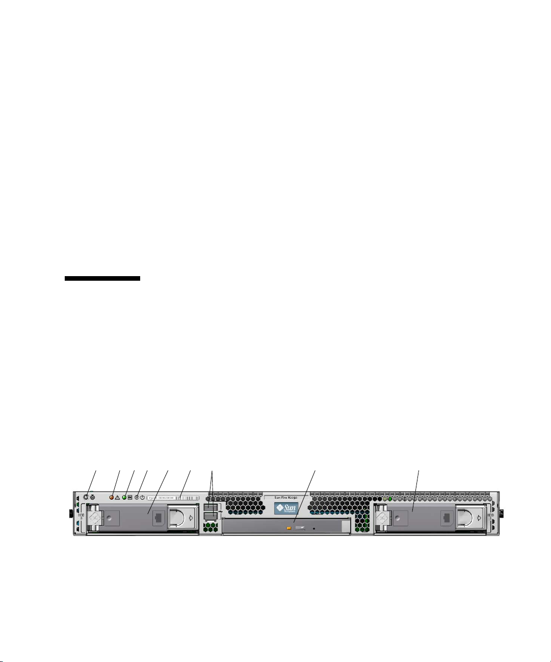
FIGURE 1-1 shows the front panel of the Sun Fire X2250 server.
FIGURE 1-1 Front Panel
21345 7896
1-4 Sun Fire X2250 Server Service Manual • April 2009
Page 17
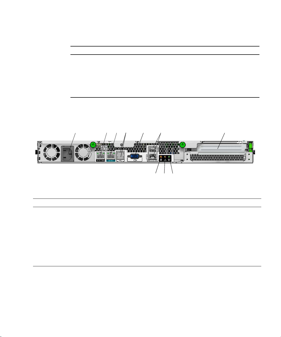
TABLE 1-2 Front Panel
Label Button/LED/Port Label Button/LED/Port
1 Locate LED/Switch 6 System serial label
2 Fault LED 7 USB 2.0 connectors (2)
3 Power/OK LED 8 Optional DVD drive
4 Power button 9 Optional SATA hard disk drive 1
5 Optional SATA hard disk drive 0
FIGURE 1-2 shows the back panel of the Sun Fire X2250 server.
FIGURE 1-2 Back Panel
2
1
TABLE 1-3 Back Panel
Label Connector/Slot Label Connector/Slot
1 AC Power connector 6 Gigabit Ethernet ports (LAN-0 top, LAN-1
2 Network Management (NET MGT) Ethernet
port
3 Serial Management (SER MGT) / RS-232-F
RJ-45 serial port
4 USB 2.0 connectors (2) 9 Power/OK LED
5 On-board HD15 video connector 10 PCI Express slot
34 5
7 Locate LED
8 Fault LED
7
6
9
8
bottom)
10
1.3.2 Internal Components
FIGURE 1-3 shows the locations of the components inside the Sun Fire X2250 server.
Chapter 1 Sun Fire X2250 Server Overview 1-5
Page 18
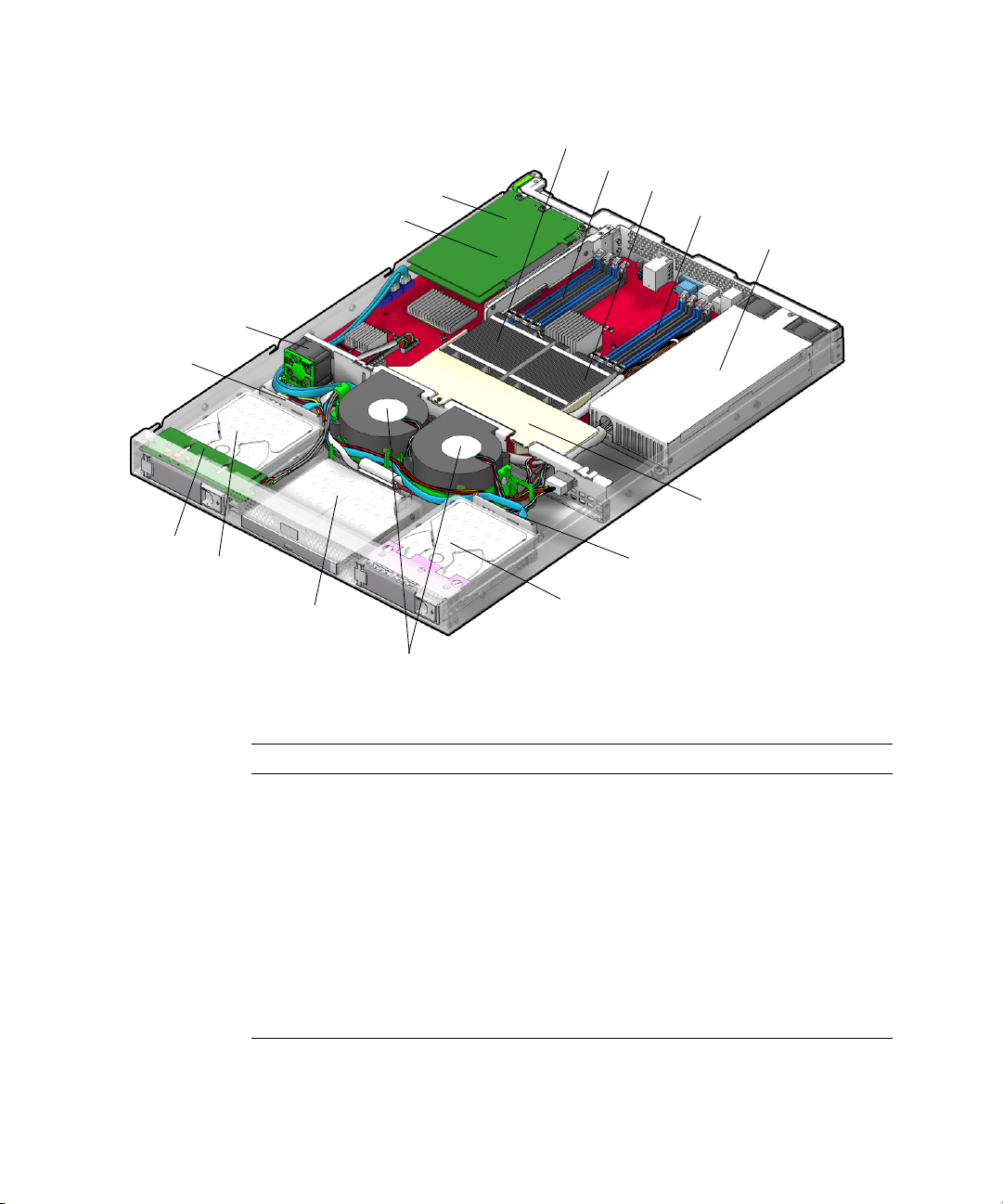
FIGURE 1-3 Sun Fire X2250 Server System Components
1
16
15
14
2
3
4
5
6
7
13
12
8
9
11
10
TABLE 1-4 Sun Fire X2250 Server Internal Components
Label Component Label Component
1 PCI Express riser and card 9 Optional SATA hard drive 1
2 CPU 1 10 Dual blower module
3 DIMM slots (4) 11 Optional DVD drive
4 CPU 0 12 Optional SATA hard drive 0
5 DIMM slots (4) 13 I/O board
6 Power supply 14 HDD 0 backplane
7 Air duct 15 Single fan module
8 HDD 1 backplane 16 System battery (located under
the PCI Express card)
1-6 Sun Fire X2250 Server Service Manual • April 2009
Page 19
1.4 Powering On and Powering Off the Server
You only need to apply standby power to the server at this point so that you can
perform initial configuration of the service processor. Procedures for powering on to main
power mode and for shutting down from main power mode are also included in this
section, for your reference.
1.4.1 Applying Standby Power for Initial Service Processor Configuration
Use this procedure to apply standby power to the service processor (SP) before initial
configuration.
Caution – Do not operate the server without all fans, component heatsinks, air baffles,
and the cover installed. Severe damage to server components can occur if
without adequate cooling mechanisms.
1. Connect grounded AC power cords to the AC power connector on the back
panel of the server and to a grounded AC power outlet.
operated
Note – At this point, standby power is supplied only to the service processor and power
supply fans. Do not apply main power to the rest of the server until you are ready to
install a platform operating system.
2. Continue with initial software setup tasks, as described in Sun Fire X2250 Server
Installation Guide (820-4591).
Chapter 1 Sun Fire X2250 Server Overview 1-7
Page 20
1.4.2 Powering On Main Power Mode
To power on main power for all server components:
1. Verify that the power cord has been connected and that standby power is on.
In standby power mode, the Power/OK LED on the front panel flashes. See
FIGURE 1-1.
2. Use a non-metallic stylus to press and release the recessed Power button on the
server front panel.
When main power is applied to the full server, the Power/OK LED next to the
Power button lights and remains lit.
1.4.3 Shutting Down Main Power Mode
To power off the server from main power mode, use one of the following two
methods:
■ Graceful shutdown: Use a non-metallic stylus to press and release the Power
button on the front panel. This causes Advanced Configuration and Power
Interface (ACPI) enabled operating systems to perform an orderly shutdown of
the operating system. Servers not running ACPI-enabled operating systems will
shut down to standby power mode immediately.
■ Emergency shutdown: Press and hold the Power button for four seconds to force
the main power off and enter standby power mode. When the main power is off,
the Power/OK LED on the front panel will begin flashing, indicating that the
server is in standby power mode.
Caution – To completely power off the server, you must disconnect the AC power cords
from the back panel of the server.
1-8 Sun Fire X2250 Server Service Manual • April 2009
Page 21

1.4.4 Clearing the CMOS
You can use this procedure to clear the server's CMOS settings in the case of a system
hang.
For example, if the server hangs because of incorrect settings and will not boot, use
this procedure to invalidate the settings and reboot with the default settings.
1. Remove the AC power cord.
See
FIGURE 1-2 for the location of the power cord connection.
2. Remove the battery for 30 seconds, then reinsert it.
See Chapter 4 for instructions on removing and replacing the battery.
3. Reinsert the AC power cord.
1.5 Customer-Orderable Components
You can order additional components and replacement parts for the Sun Fire X2250
server.
Contact your local Sun sales representative for more information. For the most
up-to-date component information, see the components list on the following web
site:
http://sunsolve.sun.com/handbook_pub/Systems/
Chapter 1 Sun Fire X2250 Server Overview 1-9
Page 22

1-10 Sun Fire X2250 Server Service Manual • April 2009
Page 23

CHAPTER
2
Troubleshooting
This chapter contains information on troubleshooting procedures and technical
support contacts.
The following sections are included in this chapter:
■ Section 2.1, “Troubleshooting Overview” on page 2-2
■ Section 2.2, “Performing Visual Inspections” on page 2-2
■ Section 2.3, “Troubleshooting Procedures” on page 2-4
■ Section 2.4, “Getting Technical Assistance” on page 2-7
2-1
Page 24

2.1 Troubleshooting Overview
Before troubleshooting your specific server problem, answer the following questions:
■ What events occurred prior to the failure?
■ Was any hardware or software modified or installed?
■ Was the server recently installed or moved?
■ How long has the server exhibited symptoms?
■ What is the duration or frequency of the problem?
After you have assessed the problem and noted your current configuration and
environment, you can choose from several ways to troubleshoot your server:
■ Visually inspect your system as described in Section 2.2, “Performing Visual
Inspections” on page 2-2.
■ View the troubleshooting procedures in Section 2.3, “Troubleshooting Procedures”
on page 2-4 to see if any of them solve the problem.
■ If the BIOS halts without displaying an error message, see the Port 80 LED for
BIOS POST messages. Appendix B lists the descriptions of the BIOS POST codes.
■ Execute a diagnostics test as described in Chapter 3.
■ If you are not able to resolve the problem, contact Sun technical support. Support
contact information is provided in Section 2.4, “Getting Technical Assistance” on
page 2-7.
2.2 Performing Visual Inspections
Improperly set controls and loose or improperly connected cables are common causes
of problems with hardware components. When investigating a system problem, first
check all the external switches, controls, and cable connections. See Section 2.2.1,
“Performing an External Visual Inspection” on page 2-3.
If this does not resolve your problem, then visually inspect the system’s interior
hardware for problems, such as a loose card, cable connector, or mounting screw. See
Section 2.2.2, “Performing an Internal Visual Inspection” on page 2-3.
2-2 Sun Fire X2250 Server Service Manual • April 2009
Page 25
2.2.1 Performing an External Visual Inspection
1. Turn off the system and any attached peripherals (if applicable).
2. Verify that all power cables are properly connected to the system, the monitor,
and the peripherals, and check their power sources.
3. Inspect connections to any attached devices, including network cables,
keyboard, monitor, and mouse, as well as any devices attached to the serial port.
2.2.2 Performing an Internal Visual Inspection
1. Shut down the operating system, if necessary.
2. Disconnect the power cord from the back of the system.
3. Turn off any attached peripherals.
4. Remove the server cover, following the precautions and procedures in
Section 4.2, “Installation Precautions” on page 4-2.
Caution – Some components, such as the heatsink, can become extremely hot
during system operations. Allow these components to cool before handling them.
5. Verify that the components are fully seated in their sockets or connectors and
that the sockets are clean.
6. Verify that all cables inside the system are firmly attached to their appropriate
connectors.
7. Replace the top cover.
8. Reconnect the system and any attached peripherals to their power sources, and
then power them on.
Chapter 2 Troubleshooting 2-3
Page 26

2.3 Troubleshooting Procedures
TABLE 2-1 lists problems that might arise as you use your server. Possible solutions
are listed for each problem. If the solutions listed here do not fix the problem, run the
appropriate diagnostic test (see Chapter 3).
TABLE 2-1 Troubleshooting Procedures
Problem Possible solution
Server does not
power on when you
press the front panel
Power button.
Server powers on, but
the monitor does not.
CD or DVD does not
eject from the media
tray when you press
the Eject button.
Server does not
power off when the
front panel Power
button is pressed.
The network status
indicator does not
light up.
An external device
connected to a USB
connector does not
work.
Keep notes on the following situations in case you need to call Sun
service:
• Is the Power/OK LED illuminated on the front of the system?
(Ensure that the power cord is connected to the system and to a
grounded power receptacle.)
• Does the wall outlet have power? Test by connecting another
device.
• Does the monitor sync within 1-2 minutes after power on? (The
green LED on the monitor stops flashing and remains illuminated.)
• Is the Power button for the monitor turned on?
• Is the monitor power cord connected to a wall outlet?
• Does the wall outlet have power? Test by connecting another
device.
• Move the mouse or press any key on the keyboard. The drive
might be in the low power mode.
• Use the utility software installed on your server to eject the CD.
• Ensure that the media in the device is not in use and is not
mounted by the operating system.
• Try all of the power-off options shown in Section 1.4.3, “Shutting
Down Main Power Mode” on page 1-8.
• If the server still does not power off, disconnect the power cable
from the rear of the chassis.
• Check the cabling and network equipment to verify that all cables
are correctly seated.
• Reinstall the network drivers.
• Reduce the number of external devices connected to a USB hub.
• Refer to the documentation that comes with the device.
2-4 Sun Fire X2250 Server Service Manual • April 2009
Page 27

TABLE 2-1 Troubleshooting Procedures (Continued)
Problem Possible solution
System cannot read
the hard disk
information.
Do the following:
1. Turn off the server by pressing the Power button.
2. Remove the top cover.
3. Verify that the power and data cables are connected to the disk
drive and that the pins in the cable and connector are not bent.
4. Verify that the drives are cabled properly to the hard drive. See
Chapter 4 for information on hard drive cabling.
5. Replace the top cover.
6. Turn on the server.
System cannot read
the CD information.
Check the following:
• Are you using the correct type of CD?
• Is the CD properly inserted into the drive?
• Is the CD clean and unscratched?
• Are the cables connected to the DVD-ROM drive?
Keyboard or mouse
does not respond to
action.
• Verify that the mouse and keyboard cables are connected to the
on-board USB 2.0 connectors on the server.
• Verify that the server is powered on and that the front Power/OK
LED is illuminated.
Server appears to be
in low power mode,
but the Power/OK
LED does not blink.
Server is hung or
frozen: No response
from mouse or
keyboard or any
application.
The Power/OK LED only blinks when all server components are in
low power mode. A tape drive might be connected to your server.
Because tape drives do not enter low power mode, the Power/OK
LED does not blink.
Try to access your system from a different server on the network:
1. On another system, type ping IP_address_of_X2250
2. If a response is returned, then try logging in to the Sun Fire X2250
server using either telnet, ssh,orrlogin.
3. If you successfully log in, list the running processes using the ps
command.
4. Kill any processes that appear unresponsive or should not be
running, by using the kill process_ID command.
5. Check the responsiveness of the Sun Fire X2250 server after each
process is killed.
If the above procedure does not work, power cycle the server:
1. Press the Power button to power off the server and wait 20 to 30
seconds.
2. Press the Power button again to power on the system.
Chapter 2 Troubleshooting 2-5
Page 28

TABLE 2-1 Troubleshooting Procedures (Continued)
Problem Possible solution
No video is displayed
on the monitor
screen.
Check the following:
• Is the monitor cable connected to the video connector?
• Does the monitor work when connected to another system?
• If you have another monitor, does it work when connected to the
original system?
• If, after POST and BIOS complete, you no longer see video output
on your monitor and only see a flashing cursor, check the
configuration of the operating system to determine if it is
configured to redirect its output exclusively over the serial line.
External device is not
working.
• Check the documentation that came with the device to see if any
device drivers must be installed.
• Verify that the cables for the external device are firmly connected
and that the pins in the cable and connector are not bent.
• Power off the system, reattach the external device, and power on
the system.
Newly installed
memory is not
detected.
• Verify that the memory is properly seated in the DIMM sockets.
• Move the memory to the another DIMM socket to determine
whether the socket is defective.
• Verify that you are using 2 GB or 4 GB (667-MHz) fully-buffered
DIMM modules with 3.05 cm max. height.
• Verify that the memory modules are installed in pairs.
2-6 Sun Fire X2250 Server Service Manual • April 2009
Page 29

2.4 Getting Technical Assistance
If the troubleshooting procedures in this chapter fail to solve your problem, see
TABLE 2-2, which lists the Sun web sites and telephone numbers for additional
technical support.
TABLE 2-2 Sun Web Sites and Telephone Numbers
Server Documents and Support Resources URL or Telephone Number
PDF files for all the current Sun Fire X2250 server
documents.
http://docs.sun.com/app/docs/prod/sf.x2250
Solaris and other software documents. This web site
has full search capabilities.
Discussion and troubleshooting forums. http://supportforum.sun.com/
Support, diagnostic tools, and alerts for all Sun
products.
SM
SunSolve
patches. Lists some system specifications,
troubleshooting and maintenance information, and
other tools.
Service support phone numbers. 1-800-872-4786 (1-800-USA-4Sun), Select Option 1.
International telephone numbers for Sun support. http://www.sun.com/service/contacting/
Warranty and contract support contacts. Links to
other service tools.
Warranties for every Sun product. http://www.sun.com/service/support/warranty
web site. Contains links to software
http://docs.sun.com
http://www.sun.com/bigadmin/
http://www.sunsolve.sun.com/handbook_pub/
solution.html
http://www.sun.com/service/online/
Chapter 2 Troubleshooting 2-7
Page 30

2-8 Sun Fire X2250 Server Service Manual • April 2009
Page 31

CHAPTER
3
Performing Diagnostics
This chapter assists you with using the Diagnostics application on the Sun Fire X2250
Server Tools & Drivers CD. The Tools & Drivers CD is available separately with the
optional Sun Fire X2250 media and documentation kit. For more information on
using the Tools & Drivers CD software, see Appendix B.
Diagnostic output is accessible on systems that are running supported Linux or
Solaris operating systems. To view diagnostic output on a Windows system, you
must use a USB diskette drive attached to your server. For information, see
Section 3.6.6, “Accessing the Diagnostic Partition on the Windows Server 2003
Operating System” on page 3-16.
If you are having specific problems with your system, use the Pc-Check Diagnostics
software to diagnose and resolve these issues.
The following sections are included in this chapter:
■ Section 3.1, “Pc-Check Diagnostics Overview” on page 3-2
■ Section 3.2, “System Information Menu Options” on page 3-3
■ Section 3.3, “Advanced Diagnostics Tests Menu Options” on page 3-4
■ Section 3.4, “Immediate Burn-in Testing” on page 3-7
■ Section 3.5, “Deferred Burn-in Testing” on page 3-9
■ Section 3.6, “Create Diagnostic Partition Option” on page 3-10
■ Section 3.7, “Show Results Summary” on page 3-16
■ Section 3.8, “Print Results Report” on page 3-18
■ Section 3.9, “About Pc-Check” on page 3-18
■ Section 3.10, “Exit to DOS” on page 3-18
3-1
Page 32

3.1 Pc-Check Diagnostics Overview
Sun Fire X2250 server diagnostics are contained in the DOS-based Pc-Check utility.
This program can be accessed and executed only from the Sun Fire X2250 Server
Tools & Drivers CD. Pc-Check was designed to detect and test all motherboard
components, ports, and slots.
If you encounter any hardware-related error message (such as memory errors or hard
disk errors) on your Sun Fire X2250 server, run one of the following:
■ Advanced Diagnostics Test: A specific hardware component test
■ Immediate Burn-in Test: A Sun Fire X2250 server diagnostic test script
The following procedure describes how to access these test options from the Sun Fire
X2250 Server Tools & Drivers CD.
3.1.1 Accessing the Pc-Check Diagnostics Software
1. Do one of the following, depending on which method you are using to access
the Pc-Check diagnostics software:
■ If your server has a DVD drive installed: Insert the Sun Fire X2250 Server Tools &
Drivers CD into your DVD drive and reboot the system.
■ If you are running the Pc-Check software from a PXE server: Follow the instructions in
Appendix B to set up the PXE server.
The system boots to the Sun Fire X2250 Server Tools & Drivers CD main menu.
2. Type 1 to run the hardware diagnostics software.
The system information loads, the Diagnostics main menu opens, and the
following menu options are displayed:
■ System Information Menu
■ Advanced Diagnostics Tests
■ Immediate Burn-in Testing
■ Deferred Burn-in Testing
■ Create Diagnostic Partition
■ Show Results Summary
■ Print Results Report
■ About PC-CHECK
■ Exit to DOS
3-2 Sun Fire X2250 Server Service Manual • April 2009
Page 33

To run a specific hardware component test, select Advanced Diagnostics Test.Torun
one of the test scripts supplied by Sun, select Immediate Burn-in Testing.
Navigate through the menu items by pressing the arrow keys located on the
keyboard to move to a menu selection, the Enter key to select a menu selection, and
the ESC key to exit a menu. Navigation instructions are shown at the bottom of each
screen.
The following sections in this chapter describe the menu items and tests in detail.
3.2 System Information Menu Options
TABLE 3-1 describes each option in the System Information menu.
TABLE 3-1 System Information Menu Options
Option Description
System Overview Includes basic information about your system,
motherboard, BIOS, processor, memory cache, drives,
video, modem, network, buses, and ports.
Hardware ID Image Enables you to create a document showing information
about your system, including comparisons between the
updates and the newest versions of your system. XML
is the format used to create and display this
information, though you can also choose a text format
(.txt) as well.
System Management Information Provides information obtained from the system about
the BIOS type, system, motherboard, enclosure,
processors, memory modules, cache, slots, system event
log, memory array, memory devices, memory device
mapped addresses, and system boot.
PCI Bus Information Includes details about specific devices from
pci-config space within the system, similar to the
System Management Information section.
IDE Bus Information Shows the master/slave devices on the primary and
secondary IDE controllers.
PCMCIA/CardBus Info Not applicable for the Sun Fire X2250 server.
Interrupt Vectors Lists and details device interrupt vector information.
IRQ Information Shows hardware interrupt assignments.
Device Drivers Shows device drivers loaded under Open DOS.
Chapter 3 Performing Diagnostics 3-3
Page 34

TABLE 3-1 System Information Menu Options (Continued)
Option Description
APM Information Tests the Advanced Power Management (APM)
capabilities of the system. You can choose to change the
power state, view the power status, indicate CPU usage,
get a PM event, or change the interface mode.
I/O Port Browser Shows the I/O port assignment for the hardware
devices on the system.
Memory Browser Enables you to view the mapped memory for the entire
system.
Sector Browser Reads sector information from the hard disks and DVD
disks sector by sector.
CPU Frequency Monitor Tests the processor speed.
CMOS RAM Utilities Shows the CMOS settings of the system.
SCSI Utilities Not applicable for the Sun Fire X2250 server.
Text File Editor Opens a file editor.
Start-Up Options Enables you to set up options for diagnostics testing.
3.3 Advanced Diagnostics Tests Menu Options
TABLE 3-2 gives the name and a brief description of each option in the Advanced
Diagnostics Tests menu.
TABLE 3-2 Advanced Diagnostics Tests Menu Options
Option Description
Processor Details information about the processor, and includes a
Processor Tests menu to test the processor on the
system.
Memory Details information about the memory, and includes a
Memory Tests menu to test the memory on the system.
Also lists each type of memory in the system, such as
system, cache, or video memory.
Motherboard Details information about the motherboard, and
includes a Motherboard Tests menu to test the
motherboard on the system.
3-4 Sun Fire X2250 Server Service Manual • April 2009
Page 35

TABLE 3-2 Advanced Diagnostics Tests Menu Options (Continued)
Option Description
Diskettes Not applicable for the Sun Fire X2250 server.
Hard Disks Details information about the hard disk, and includes a
Hard Disk Tests menu to test hard disks on the system.
Refer to Section 3.3.1, “Testing the Hard Disk” on
page 3-6, for detailed information about testing hard
disks and script information.
CD-ROM/DVD Includes a CD-ROM/DVD menu to test DVD devices
on the system.
ATAPI Devices Details information about devices attached to the IDE
controllers on the system other than a DVD or hard
disks (for example, zip drives).
Serial Ports Details information about the serial port, and includes a
Serial Ports Tests menu to test serial ports on the
system.
Parallel Ports Not applicable for the Sun Fire X2250 server.
Modems Not applicable for the Sun Fire X2250 server.
ATA Includes an Advanced Technology Attachment (ATA)
test menu.
USB Details information about the USB devices on the
system, and includes a USB Tests menu to test the USB.
FireWire Not applicable for the Sun Fire X2250 server.
Network Performs network register controller tests.
Keyboard Includes a Keyboard Test menu with options for
performing different tests on the keyboard.
Mouse Details information about the mouse, and includes a
menu to test the mouse on the system.
Joystick Not applicable for the Sun Fire X2250 server.
Audio Not applicable for the Sun Fire X2250 server.
Video Details information about the video card. Initially, the
monitor might flicker, but then it brings up a Video Test
Options menu that enables you to perform various
video tests.
Printers Printers are not available for the Sun Fire X2250 server.
Firmware - ACPI Details information about Advanced Configurable
Power Interface (ACPI), and includes an ACPI Tests
menu to test ACPI.
Chapter 3 Performing Diagnostics 3-5
Page 36

3.3.1 Testing the Hard Disk
1. From the main menu, choose Advanced Diagnostics Tests.
2. From the Advanced Diagnostics menu, choose Hard Disks.
3. From the Select Drive menu, choose the hard disk you are testing.
The Hard Disk Diagnostics window opens, showing both the information for the
hard disk you have selected and the Hard Disk Tests menu.
The Hard Disk Tests menu displays the following options:
■ Select Drive
■ Test Settings
■ Read Test
■ Read Verify Test
■ Non-Destructive Write Test
■ Destructive Write Test
■ Mechanics Stress Test
■ Internal Cache Test
■ View Error Log
■ Utilities Menu
■ Exit
The Media Test options include the Read Test, the Read Verify Test, the
Non-Destructive Write Test, and the Destructive Write Test. These tests are relevant
to testing the media associated with the hard drive hardware, such as the physical
disk.
Caution – Running the Destructive Write Test destroys any data that is on the disk.
The Device Test options include the Mechanics Stress Test and the Internal Cache
Test. These tests are relevant to testing non-media-related devices associated with the
hard drive hardware, such as the head and internal cache.
In addition to choosing any of these tests, you can also define several parameters of
the test.
You can change the parameters within the Test Settings option. Your options within
Test Settings include the following:
■ Media Test Settings
Enables you to select the test time duration, the percentage of the hard disk to
test, and the sectors to be tested on the hard disk.
3-6 Sun Fire X2250 Server Service Manual • April 2009
Page 37

■ Device Test Settings
Enables you to select the test time durations of the devices and the test level.
■ Number of Retries
Enables you to select the number of times to retry testing a device before
terminating the test.
■ Maximum Errors
Enables you to select the number of errors allowed before terminating the test.
■ Check SMART First
SMART stands for Smart Monitoring Analysis Reporting Test.
■ HPA Protection
HPA stands for Host Protected Area.
■ Exit
3.4 Immediate Burn-in Testing
The Immediate Burn-In Testing option enables you to run burn-in test scripts on your
server. Three scripts have already been created for testing your system:
■ quick.tst – This script performs a high level test of all hardware components,
including those components that require user input, as well as a more in-depth
memory test. The user must interact with the Pc-Check software to progress
through these interactive tests. The tests cannot be run unattended and do not
contain "timeout" facilities. The interactive tests will wait until the user provides
the correct input.
■ noinput.tst – This script is used as a first triage of any hardware-related
problems or issues. The script performs a high level test of most hardware
components, excluding those components that require user input (keyboard,
mouse, sound, video). This test does not require user input.
■ full.tst – This script performs the most detailed and comprehensive test on all
hardware components, including those components that require user input. This
script contains a more in-depth memory test than quick.tst, as well as external
port tests (which may require loopback connectors). The user must interact with
the test utility to progress through these interactive tests.
Tip – Each of these scripts tests the operating status of your entire system. If you
want to test only a certain percentage of your system’s hard drives, refer to
Section 3.3.1, “Testing the Hard Disk” on page 3-6 to change the test options.
Chapter 3 Performing Diagnostics 3-7
Page 38

When you select the Immediate Burn-in Testing menu option, the Continuous
Burn-in Testing window is displayed. The screen includes the list of options shown
in
TABLE 3-3 for running the tests. When a quick.tst, noinput.tst,orfull.tst
script is loaded, the defaults indicated in the third column are automatically loaded.
TABLE 3-3 Continuous Burn-in Testing Options
Default Using
quick.tst,
Option Default – General
Pass Control Overall Time Overall Passes Individual Passes,
Duration 01:00 1 Any number to
Script File N/A quick.tst,
Report File None None User-defined
Journal File None D:\noinput.jrl,
Journal Options Failed Tests All Tests, Absent
Pause on Error N N Y or N
Screen Display Control Panel Control Panel Control Panel or
POST Card N N Y or N
Beep Codes N N Y or N
Maximum Fails Disabled Disabled 1-9999
noinput.tst, or
full.tst Script All Possible Choices
Overall Passes, or
Overall Time
designates the time
duration of the test
quick.tst,
noinput.tst, or
full.tst
D:\quick.jrl, or
D:\full.jrl
Devices, and Test
Summary
noiniput.tst, or
full.tst
User-defined
Failed Tests, All
Tests, Absent
Devices, and Test
Summary
Running Tests
3.4.1 Loading Scripts for Immediate Burn-in Testing
To load one of the scripts available to test the devices on your system, do the
following:
3-8 Sun Fire X2250 Server Service Manual • April 2009
Page 39

1. From the main menu, choose Immediate Burn-in Testing.
The top portion of the window lists the options described in
TABLE 3-3, and the
bottom portion of the window lists the Burn-in menu options.
2. Complete one of the following options:
■ Load Burn-in Script
Enter one of the following:
■ quick.tst, noinput.tst,orfull.tst
■ If you have created and saved your own script, enter d:\testname.tst
Where testname is the name of the script that you have created.
■ Save Burn-in Script
To save a burn-in script that you have created, enter d:\testname.tst
Where testname is the name of the script that you have created.
■ Change Options
Opens the Burn-in Options menu, which enables you to modify the various
options listed in
■ Select Tests
TABLE 3-3 for the currently loaded test script.
Opens a listing of the tests available for your server configuration and the
currently loaded test script.
■ Perform Burn-in Tests
Runs the currently loaded burn-in test script.
3.5 Deferred Burn-in Testing
You can use the Deferred Burn-in Testing option to create and save your own scripts
to run at a later time.
3.5.1 Creating and Saving Scripts for Deferred Burn-in Testing
1. From the main menu, choose Deferred Burn-in Testing.
The top portion of the window lists the options described in
bottom portion of the window lists the Burn-in menu options.
Chapter 3 Performing Diagnostics 3-9
TABLE 3-3, and the
Page 40

2. Complete one of the following options:
■ Load Burn-in Script
Enter one of the following:
■ quick.tst, noinput.tst,orfull.tst
■ If you have created and saved your own script, enter d:\testname.tst
Where testname is the name that you have created.
■ Save Burn-in Script
To save a burn-in script that you have created, enter d:\testname.tst
Where testname is the name of the script that you have created.
■ Change Options
Opens the Burn-in Options menu, which enables you to modify the various
options listed in
■ Select Tests
TABLE 3-3 for the currently loaded test script.
Opens a listing of all the possible types of tests available for you to run for the
currently loaded test script.
3.6 Create Diagnostic Partition Option
The diagnostic partition is preinstalled on the Sun Fire X2250 server. You need to
reinstall the diagnostic partition only if you have reformatted your hard drive. Using
the Erase Primary Boot Hard Disk utility on the Sun Fire X2250 Server Tools &
Drivers CD preserves the diagnostic partition.
The Create Diagnostic Partition option installs a diagnostic partition on the first
bootable disk seen by the Sun Fire X2250 server. The first bootable disk is on the
primary/master SATA device.
Note – If you are running the Pc-Check Diagnostics software from a PXE server, you
do not need to follow the instructions in these procedures for inserting the Tools &
Drivers CD into the DVD tray. See Section B.4, “Booting the Tools & Drivers CD
From a PXE Server” on page B-7.
The following sections explain how to create and access the diagnostic partition on
the Sun Fire X2250 server:
■ Section 3.6.1, “Removing Existing Partitions From a Hard Disk” on page 3-11
■ Section 3.6.2, “Adding a Diagnostic Partition to the First Bootable Disk” on
page 3-12
3-10 Sun Fire X2250 Server Service Manual • April 2009
Page 41

■ Section 3.6.3, “Creating a Log File on the Diagnostic Partition” on page 3-12
■ Section 3.6.4, “Accessing the Diagnostic Partition on a Red Hat Linux System” on
page 3-13
■ Section 3.6.5, “Accessing the Diagnostic Partition on the Solaris 10 Operating
System” on page 3-15
■ Section 3.6.6, “Accessing the Diagnostic Partition on the Windows Server 2003
Operating System” on page 3-16
3.6.1 Removing Existing Partitions From a Hard Disk
The Create Diagnostic Partition option creates a diagnostic partition on a hard disk
only if that hard disk is completely free of any partitions. You need to delete any
existing partitions from a hard disk if you plan to use the hard disk to create a
diagnostic partition on it.
Caution – Removing all hard disk partitions destroys all data on the disk.
There are two ways to remove existing partitions from the hard disk:
■ Use the Erase Primary Boot Hard Disk utility (Option 3 on the Tools & Drivers CD
main menu).
■ Use the following procedure:
1. Insert the Tools & Drivers CD into the DVD tray.
2. Reboot the server.
3. From the Tools & Drivers CD main menu, type 4 to exit to DOS.
4. Type fdisk at the command prompt, and press the Enter key.
5. Type 4 to select an alternate fixed disk.
The second hard disk as seen from fdisk is the first bootable disk of the system.
The first hard disk as seen from fdisk is the bootable Tools & Drivers CD.
Caution – When performing the following tests, be careful not to delete any
operating system partitions that you want to keep. Removing hard disk partitions
destroys all data on the disk.
6. Type 2 to delete the DOS partition.
7. Type 1 or 2 depending on the type of partition you want to delete.
8. Type the number of the partition you want to delete.
Chapter 3 Performing Diagnostics 3-11
Page 42

9. Type Y to erase the data and the partition.
10. Repeat Step 6 through Step 9 until all partitions have been deleted.
11. Press the Esc key to exit, and press any key to reboot the server.
3.6.2 Adding a Diagnostic Partition to the First Bootable Disk
Pc-Check can view only the first or second hard disk on the system from the boot
loader. The software automatically installs the diagnostic partition on the first
bootable disk.
To add the diagnostic partition on the first bootable disk:
1. Insert the Tools & Drivers CD into the DVD tray.
2. Reboot the server.
3. At the Tools & Drivers CD main menu, type 1 to run Hardware Diagnostics.
4. From the main menu, choose Create Diagnostic Partition.
■ If the first bootable disk is clear of partitions, the Sun Microsystems Partitioning
Utility window appears. It states: “Your primary hard disk is not partitioned.
Would you like to partition it now?”
■ Select Yes and press Enter.
■ A window appears, stating, “Partitioning complete. Your machine will now be
restarted.”
■ If the first bootable disk is not clear of partitions, a window appears stating that
the software is unable to create a hardware diagnostic partition because there are
already partitions on the disk.
■ If this happens, go to Section 3.6.1, “Removing Existing Partitions From a Hard
Disk” on page 3-11 to remove the partitions from the disk.
■ Repeat Step 1 through Step 4 of this procedure.
5. Press Enter to reboot your server.
3.6.3 Creating a Log File on the Diagnostic Partition
All the scripts that are loadable with the hardware diagnostics software are
predefined, with logging to the diagnostic partition enabled. The names of log files
correspond to the name of the script. For example, a script named noinput.tst
creates a log file named noinput.jrl.
3-12 Sun Fire X2250 Server Service Manual • April 2009
Page 43

The following procedure shows an example of how to create and access a log file on
the diagnostic partition for the noinput.tst script.
1. Insert the Tools & Drivers CD into the DVD tray.
2. Reboot the server.
3. From the Tools & Drivers CD main menu, choose 1 to run Hardware
Diagnostics.
4. From the Hardware Diagnostics main menu, choose Immediate Burn-In Testing.
5. Select Load Burn-in Script.
6. Type noinput.tst and press Enter.
If you are using a test you have created yourself, you need to enter
d:\testname.tst into the Load Burn-in Script field, where testname is the name of
the test you have created.
7. Select Perform Burn-in Tests to run the script.
8. When the tests are complete, press the Esc key to exit the Display Results
window.
9. Select Exit to DOS and press Enter.
10. At the DOS prompt, type the following:
C:> d:
11. Type the following to list the contents of the diagnostic partition.:
D:> dir
The noinput.jrl log is displayed.
3.6.4 Accessing the Diagnostic Partition on a Red Hat Linux System
To access the diagnostic partition on a Red Had Linux operating system:
1. Remove the Tools & Drivers CD from the DVD tray.
2. Reboot the server and start the Red Hat Linux operating system.
3. Log in as root (superuser).
Chapter 3 Performing Diagnostics 3-13
Page 44

4. Determine if your diagnostic partition has been configured to be mounted by
typing the following command:
# ls /diagpart
■ If this command fails to list the log files created by the hardware diagnostics
software, then the operating system has never been configured to mount the
diagnostic partition. Continue to Step 5.
■ If this command succeeds in listing the log files created by the hardware
diagnostics software, then the operating system has already been configured to
mount the diagnostic partition. All users have read access to this partition. Only
the superuser has read/write access to this partition. You do not need to continue
this procedure.
5. Insert the Tools & Drivers CD into the DVD tray.
6. When the CD is mounted, open a terminal window.
7. Type the following command:
# cd mountpoint/drivers/linux/linux_version
Where mountpoint is the CD mountpoint and linux_version is the version of Linux
that you have installed. For example:
# cd /mnt/cdrom/drivers/linux/red_hat
8. Type the following to install the diagnostic partition:
# ./install.sh
9. Press the Enter key.
The following lines appear if the diagnostic partition is mounted successfully:
Mounting Diagnostic Partition
Installation Successful
10. Type the following command:
# ls /diagpart
The contents of the diagnostic partition are listed.
3-14 Sun Fire X2250 Server Service Manual • April 2009
Page 45

3.6.5 Accessing the Diagnostic Partition on the Solaris 10 Operating System
To access the diagnostic partition on the Solaris 10 Operating System:
1. Remove the Tools & Drivers CD from the DVD tray.
2. Reboot the machine and start the Solaris 10 Operating System.
3. Log in as root (superuser).
4. Type the following command to determine whether your diagnostic partition
has been configured to be mounted:
# ls /diagpart
■ If this command fails to list the log files created by the hardware diagnostics
software then the operating system has never been configured to mount the
diagnostic partition. Continue to Step 5.
■ If this command succeeds in listing the log files created by the hardware
diagnostics software, then the operating system has already been configured to
mount the diagnostic partition. All users have read access to this partition. Only
the superuser has read/write access to this partition. You do not need to continue
this procedure.
5. Insert the Tools & Drivers CD into the DVD tray.
6. When the CD is mounted, open a terminal window.
7. Type the following:
# cd /cdrom/cdrom0/drivers/sx86
8. Type the following to install the diagnostic partition:
# ./install.sh
9. Press the Enter key.
The following lines appear if the diagnostic partition is mounted successfully:
Mounting Diagnostic Partition
Installing Successful
10. Type the following command to list the contents of the diagnostic partition:
# ls /diagpart
Chapter 3 Performing Diagnostics 3-15
Page 46

3.6.6 Accessing the Diagnostic Partition on the Windows Server 2003 Operating System
The Windows 2003 Server operating system does not allow you to mount a
diagnostic partition. There is no way to view or gain access to the diagnostic
partition if you are running Windows on a Sun Fire X2250 server.
The only way to retrieve the contents (log files) on the diagnostic partition is to
attach a USB diskette drive to the Sun Fire X2250 server and complete the following
procedure.
1. Connect the USB diskette drive to any USB port on the Sun Fire X2250 server.
2. Insert the Tools & Drivers CD into the DVD tray.
3. Reboot the server.
4. At the Tools & Drivers CD main menu, type 3 to exit to DOS.
5. Type the following at the DOS command prompt:
C:> d:
6. Copy the log file to the diskette.
For example, to copy a file named noinput.jrl to the diskette, type:
D:> copy d:\noinput.jrl a:\
The journal file is now saved to the diskette in the USB diskette drive.
3.7 Show Results Summary
The summary lists the tests run and shows the results. Pass, Fail, or N/A is listed for
each option.
The following is a complete listing of all options that are available with the Tools &
Drivers CD. If your own system does not have all of these options, they might not be
listed when the Show Results Summary is displayed.
■ Processor
This section shows the following tests conducted against the processor: Core
Processor Tests, AMD 64-Bit Core Tests, Math Co-Processor Tests – Pentium
Class FDIV and Pentium Class FIST, MMX Operation, 3DNow! Operation, SSE
Instruction Set, SSE2 Instruction Set, and MP Symmetry.
3-16 Sun Fire X2250 Server Service Manual • April 2009
Page 47

■ Motherboard
This section shows the following tests conducted against the motherboard:
DMA Controller Tests, System Timer Tests, Interrupt Test, Keyboard Controller
Tests, PCI Bus Tests, and CMOS RAM/Clock Tests.
■ Memory, Cache Memory, and Video Memory
This section shows the following tests conducted against the various types of
memory: Inversion Test Tree, Progressive Inv. Test, Chaotic Addressing Test,
and Block Rotation Test.
■ Input Device
This section shows the following tests conducted against the input device:
Verify Device, Keyboard Repeat, and Keyboard LEDs.
■ Mouse
This section shows the following tests conducted against the mouse: Buttons,
Ballistics, Text Mode Positioning, Text Mode Area Redefine, Graphics Mode
Positions, Graphics Area Redefine, and Graphics Cursor Redefine.
■ Video
This section shows the following tests conducted against the video: Color
Purity Test, True Color Test, Alignment Test, LCD Test, and Test Cord Test.
■ Multimedia
This section shows the following tests conducted against the multimedia
components: Internal Speaker Test, FM Synthesizer Test, PCM Sample Test,
CD/DVD Drive Read Test, CD/DVD Transfer (KB/Sec), CD/DVD Transfer
Rating, CD/DVD Drive Seek Test, CD/DVD Seek Time (ms), CD/DVD Test
Disk Read, and CD/DVD Tray Test.
■ ATAPI Devices
This section shows the following tests conducted against ATAPI devices: Linear
Read Test, Non-Destructive Write, and Random Read/Write Test.
■ Hard Disk
This section shows the following tests conducted against the hard disk: Read
Test, Read Verify Test, Non-Destructive Write Test, Destructive Write Test,
Mechanics Stress Test, and Internal Cache Test.
■ USB
This section shows the following tests conducted against the USB: Controller
Tests and Functional Tests.
■ Hardware ID
This test is used to determine the machine ID for the system. This test is not
available for the Sun Fire X2250 server.
Chapter 3 Performing Diagnostics 3-17
Page 48

3.8 Print Results Report
The Print Results Report option enables you to print system diagnostic results.
Ensure that your server is connected to a printer, and then enter the required
information to print the results.
3.9 About Pc-Check
The About Pc-Check window includes general information about Pc-Check software,
including resident and nonresident components, such as mouse devices.
3.10 Exit to DOS
You use the Exit to DOS option to exit Pc-Check and return to the DOS prompt.
3-18 Sun Fire X2250 Server Service Manual • April 2009
Page 49

CHAPTER
4
Maintaining the Sun Fire X2250 Server
This chapter describes how to add, replace, and configure components in the Sun
Fire X2250 server after it has been set up.
This chapter contains the following sections:
■ Section 4.1, “Tools and Supplies Needed” on page 4-1
■ Section 4.3, “Powering Off the Server and Removing the Cover” on page 4-3
■ Section 4.4, “Locations of Server Components” on page 4-5
■ Section 4.5, “Component Replacement Procedures” on page 4-6
To determine and isolate a faulty component, refer to Section , “Performing
Diagnostics” on page 3-1.
Note – System cooling might be affected by dust and contaminant build-up. It is
recommended that systems be opened and checked approximately every six months
or more often in dirty operating environments. Check system heatsinks, fans, and air
openings. If necessary, clean systems by brushing or blowing contaminants from the
system or by carefully vacuuming contaminants from the system.
4.1 Tools and Supplies Needed
You need the following tools and supplies for performing Sun Fire X2250 server
maintenance procedures.
■ #2 Phillips screwdriver
■ Antistatic wrist strap
4-1
Page 50

■ Alcohol pads (for CPU replacement by service personnel only)
■ 5 mm nut driver (for motherboard replacement by service personnel only)
4.2 Installation Precautions
Before removing the system’s top cover, read the following sections. These sections
contain important electrostatic discharge (ESD) precautions, along with
preinstallation and postinstallation instructions.
4.2.1 ESD Precautions
ESD can damage your processor, disk drives, expansion boards, and other
components. Always observe the following precautions before you install a system
component.
■ Do not remove a component from its protective packaging until you are ready to
install it.
■ Wear a wrist strap and attach it to the system chassis ground, or to any metal part
of the system, before handling components.
■ Press the Power button on the front of the chassis to turn off power before
removing or replacing any of the system components.
4.2.2 Preinstallation Instructions
Always perform the following steps before you install any component:
1. Turn off the system and all of the peripherals connected to it.
Caution – Failure to properly turn off the system before you start installing
components can cause serious component damage.
Caution – Follow the ESD precautions described in Section 4.2.1, “ESD Precautions”
on page 4-2 when handling a system component.
4-2 Sun Fire X2250 Server Service Manual • April 2009
Page 51

2. Remove the server cover.
See Section 4.3, “Powering Off the Server and Removing the Cover” on page 4-3
for the appropriate procedure for removing the cover from the server.
4.2.3 Postinstallation Instructions
Perform the following steps after installing a server component.
1. Ensure that all of the components are installed as described in the component
replacement instructions.
See Section 4.5, “Component Replacement Procedures” on page 4-6.
2. Reinstall any PCI-Express (PCIe) cards or peripherals that you had previously
removed.
See Section 4.5, “Component Replacement Procedures” on page 4-6.
3. Reinstall the system’s cover.
See Section 4.3, “Powering Off the Server and Removing the Cover” on page 4-3.
4. Connect all external cables to the system.
5. Power on the system.
See Section 1.4, “Powering On and Powering Off the Server” on page 1-7.
Caution – If the cover has been removed or hard drive bays do not have a drive or
filler panel installed, do not operate the server for more than ten minutes. Improper
cooling airflow might damage the system’s components.
4.3 Powering Off the Server and Removing the Cover
For your safety, perform this procedure when you are powering off the system and
removing the cover for a maintenance procedure in this chapter.
1. If the operating system (OS) is running, perform a shutdown of the OS, and
then press and release the platform Power button on the front panel.
2. Turn off all peripheral devices connected to the system.
3. Disconnect the AC power on the back panel of the server (see
Chapter 4 Maintaining the Sun Fire X2250 Server 4-3
FIGURE 1-2).
Page 52

4. Label and disconnect all peripheral cables and all telecommunication lines
connected to I/O connectors or ports on the back panel of the system.
Caution – The system’s printed circuit boards and hard disk drives contain
components that are extremely sensitive to static electricity.
5. Before handling components, attach a wrist strap to a chassis ground (any
unpainted metal surface).
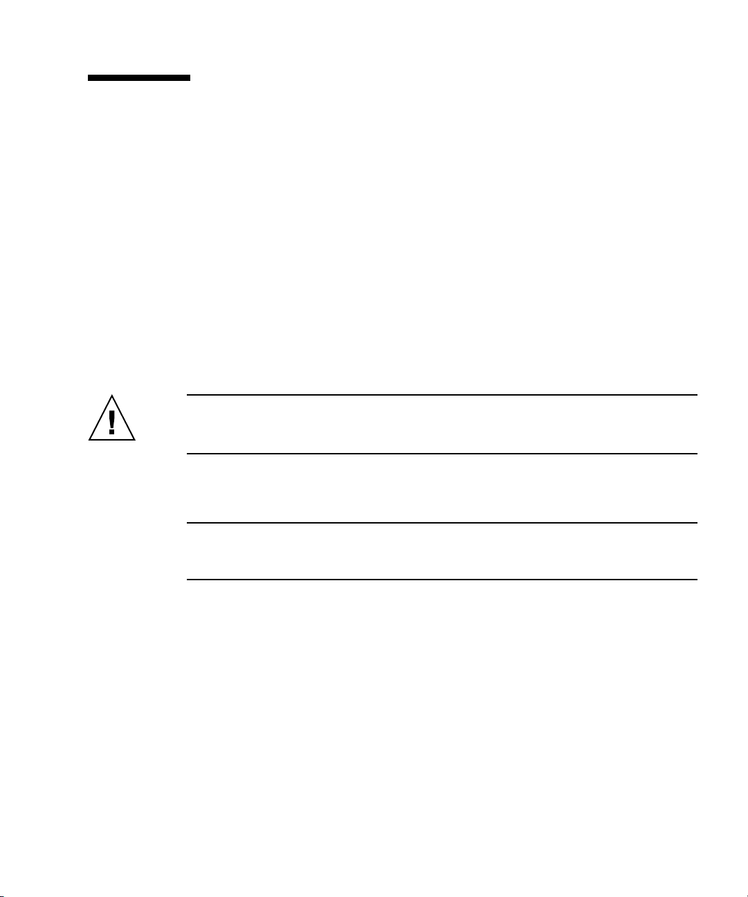
6. Loosen the two captive screws securing the cover to the chassis (see
FIGURE 4-1).
7. Pull the cover slightly toward the back of the server and then straight up to
remove it.
8. Lift the cover and remove it.
FIGURE 4-1 Removing the Server Cover
4-4 Sun Fire X2250 Server Service Manual • April 2009
Page 53

4.4 Locations of Server Components
FIGURE 4-2 Sun Fire X2250 Server System Components
2
3
1
16
15
14
4
5
6
7
13
12
9
11
10
TABLE 4-1 Sun Fire X2250 Server Internal Components
Label Component Label Component
1 PCI Express riser and card 9 Optional SATA hard drive 1
2 CPU 1 10 Dual blower module
3 DIMM slots (4) 11 Optional DVD drive
4 CPU 0 12 Optional SATA hard drive 0
5 DIMM slots (4) 13 I/O board
Chapter 4 Maintaining the Sun Fire X2250 Server 4-5
8
Page 54

TABLE 4-1 Sun Fire X2250 Server Internal Components (Continued)
Label Component Label Component
6 Power supply 14 HDD 0 backplane
7 Air duct 15 Single fan module
8 HDD 1 backplane 16 System battery (located under
the PCI Express card)
4.5 Component Replacement Procedures
The following components are customer-replaceable units (CRUs):
■ I/O board (see Section 4.5.1, “Replacing the I/O Board” on page 4-7)
■ PCIe cards and risers (see Section 4.5.2, “Replacing the PCIe Card and Riser
Assembly” on page 4-9)
■ Hard disk drives and carriers (see Section 4.5.3, “Replacing a Hard Disk Drive and
Carrier” on page 4-13)
■ Hard disk drive backplanes (see Section 4.5.4, “Replacing an HDD Backplane
Assembly” on page 4-15)
■ Optical Disk Drive (DVD or CD) drive (see Section 4.5.5, “Removing and
Installing the ODD Drive Assembly” on page 4-18)
■ Air duct (see Section 4.5.6, “Replacing the Air Duct” on page 4-20)
■ Power supply (see Section 4.5.7, “Replacing the Power Supply” on page 4-22)
■ Single fan module (see Section 4.5.8, “Replacing the Single Fan Module” on
page 4-25)
■ Dual blower modules (see Section 4.5.9, “Replacing the Dual Blower Module” on
page 4-26)
■ Memory modules (DIMMs) (see Section 4.5.10, “Replacing Memory Modules” on
page 4-28)
■ Battery (see Section 4.5.11, “Replacing the System Battery” on page 4-33)
■ CPU - new installation (see Section 4.5.13, “Installing a New CPU” on page 4-41).
■ Cable kit (see Section 4.5.14, “Replacing Cables” on page 4-45)
The following component should be replaced only by trained field service
technicians:
■ CPU - replacement (see Section 4.5.12, “Replacing a CPU and Heatsink” on
page 4-36).
■ Motherboard (see Section 4.5.15, “.Motherboard” on page 4-46)
4-6 Sun Fire X2250 Server Service Manual • April 2009
Page 55

4.5.1 Replacing the I/O Board
The following procedures describe how to remove and replace an I/O board.
4.5.1.1 Removing the I/O Board
To remove the I/O board:
1. Power off the server, including any attached peripherals, and disconnect the
server from the electrical outlet. Refer to Section 4.3, “Powering Off the Server
and Removing the Cover” on page 4-3.
2. Remove the screws securing the I/O board to the hard disk drive (HDD) cage.
FIGURE 4-3 Removing the I/O Board
3. Pull the I/O board back slightly, then upward to disengage the board from the
guides on top of the HDD cage.
4. Remove all cables connected to the I/O board.
Chapter 4 Maintaining the Sun Fire X2250 Server 4-7
Page 56

4.5.1.2 Installing the I/O Board
To install the I/O board:
1. Position the I/O board on top of the HDD cage so the openings on the board
line up with the guides on top of the HDD cage.
FIGURE 4-4 Installing the I/O Board
2. Reconnect the cables.
3. Gently push the I/O board down to engage the guides and push the board
forward to secure it.
4. Fasten the screws to secure the I/O board to the mounting bracket.
5. Check the routing of all cables for obstructions, and then reinstall the cover as
described in Section 4.3, “Powering Off the Server and Removing the Cover” on
page 4-3.
4-8 Sun Fire X2250 Server Service Manual • April 2009
Page 57

4.5.2 Replacing the PCIe Card and Riser Assembly
Note – Many of the illustrations in this section show multiple PCIe slots on the
motherboard. The Sun Fire X2250 server motherboard will only have a single PCIe
slot.
The PCIe riser assembly installed in the server is a low-profile, half-length x16 dual
connector card, supporting up to
■ Low-profile, half-length x16 single connector card up to ?W
Note – Graphics cards are not currently supported for the x16 riser assembly. Refer
to the Sun Fire X2100 M2 Server Product Notes for specifics on limits on supported
cards for this riser assembly.
FIGURE 4-5 PCIe riser assembly: x16 assembly (left) x8 assembly (right)
35W cards.
The following procedures describe how to remove or install a riser assembly and
PCIe card.
Chapter 4 Maintaining the Sun Fire X2250 Server 4-9
Page 58

Note – The examples shown in these procedures use the x8 card, but the installation
and removal instructions are the same for the x16 card. The x16 riser assembly has
one PCIe card connector, rather than two.
4.5.2.1 Removing the Riser Assembly and PCIe Card
To remove the riser assembly and PCIe card:
1. Power off the system and remove the cover as described in Section 4.3,
“Powering Off the Server and Removing the Cover” on page 4-3.
FIGURE 4-6 Removing the PCIe Card Riser Assembly
2. Placing your fingers on the two green areas on the riser assembly, pull the
assembly upward and out of the chassis. See
3. Unlatch the PCIe card and remove the card from the PCIe card riser assembly
connector. See
4-10 Sun Fire X2250 Server Service Manual • April 2009
FIGURE 4-7.
FIGURE 4-6.
Page 59

FIGURE 4-7 Removing a PCIe Card
4.5.2.2 Installing the PCIe Card and Riser Card Assembly
To install the PCIe card and riser card assembly:
1. If necessary, remove the riser card filler panel. See
FIGURE 4-8 Removing the PCIe Riser Card Filler Panel
FIGURE 4-8.
2. Insert the new PCIe card into the riser assembly and fasten the latch to secure
the card. See
FIGURE 4-9.
Chapter 4 Maintaining the Sun Fire X2250 Server 4-11
Page 60

FIGURE 4-9 Installing the PCIe Card
3. Reinstall the riser assembly into the connector on the motherboard. See
FIGURE 4-10.
FIGURE 4-10 Installing the PCIe Card Riser Assembly
4-12 Sun Fire X2250 Server Service Manual • April 2009
Page 61

4. Check the routing of all cables for obstructions, and then reinstall the cover as
described in Section 4.3, “Powering Off the Server and Removing the Cover” on
page 4-3.
4.5.3 Replacing a Hard Disk Drive and Carrier
The following procedures describe how to remove and replace a hard disk drive
(HDD) and carrier.
4.5.3.1 Removing an HDD and Carrier
To remove the HDD and carrier:
1. If you are not using an integrated-mirroring (IM) configuration, you must power
off the server before removing an HDD; it is not necessary to remove the cover.
Power off the system as described in Section 4.3, “Powering Off the Server and
Removing the Cover” on page 4-3.
If you are using an IM configuration, start with Step 2.
2. Squeeze the release latch on the HDD and carefully swing the arm to the left as
far as it will go.
FIGURE 4-11 Removing a Hard Disk Drive
Chapter 4 Maintaining the Sun Fire X2250 Server 4-13
Page 62

3. Grasp the carrier bezel with both hands and carefully pull the carrier out of the
drive bay.
Note – Avoid using the arm to remove the carrier.
4. Reinsert the HDD and carrier into the server as described in Section 4.5.3.2,
“Installing an HDD and Carrier” on page 4-14.
4.5.3.2 Installing an HDD and Carrier
Note – If you are installing a new HDD, rather than replacing an already installed
HDD, you will need to remove the empty carrier from the drive cage before
installing the new HDD. See instructions for Removing an HDD and carrier.
To install the HDD and carrier:
1. Squeeze the release latch on the HDD and carefully swing the arm to the left as
far as it will go.
FIGURE 4-12 Installing a Hard Disk Drive
2. Grasping the body of the drive in both hands, carefully guide the connector end
of the carrier into the drive bay, sliding the carrier into the bay until the latch
engages and partially closes itself.
3. Push the latch forward until it locks to secure the carrier in place.
4-14 Sun Fire X2250 Server Service Manual • April 2009
Page 63

4.5.4 Replacing an HDD Backplane Assembly
The following procedure describes how to replace the hard disk drive (HDD)
backplane assembly for HDD 0 and HDD 1.
4.5.4.1 Removing an HDD Backplane
To remove the HDD backplane:
1. Remove the HDD as described in Section 4.5.3.1, “Removing an HDD and
Carrier” on page 4-13.
This ensures that the HDD is detached from the HDD backplane assembly.
2. Remove the screws fastening the backplane assembly to the server chassis.
3. Carefully lift the HDD backplane assembly from the server chassis.
4. Disconnect the HDD power and SATA cables from the rear of the HDD
backplane assembly.
5. Remove the screws fastening the HDD backplane to the backplane bracket.
Chapter 4 Maintaining the Sun Fire X2250 Server 4-15
Page 64

FIGURE 4-13 Removing the HDD Backplane Assembly
4.5.4.2 Replacing an HDD Backplane
To install the HDD backplane assembly:
1. Fasten the screws to secure the HDD backplane to the backplane bracket.
2. Reinstall the HDD power and SATA cables to the rear of the HDD backplane
assembly.
3. Reinsert the HDD assembly into the server chassis.
4. Fasten the screws to secure the HDD backplane assembly to the server chassis.
4-16 Sun Fire X2250 Server Service Manual • April 2009
Page 65

FIGURE 4-14 Replacing the HDD Backplane Assembly
5. Reinsert the HDD as described in Section 4.5.3.2, “Installing an HDD and
Carrier” on page 4-14.
6. Check the routing of all cables for obstructions, and then reinstall the cover as
described in Section 4.3, “Powering Off the Server and Removing the Cover” on
page 4-3.
Chapter 4 Maintaining the Sun Fire X2250 Server 4-17
Page 66

4.5.5 Removing and Installing the ODD Drive Assembly
The following procedure describes how to replace the optical disk drive (ODD)
assembly. If you are not replacing a DVD drive, go to Section 4.5.5.2, “Installing the
ODD Drive Assembly” on page 4-19.
4.5.5.1 Removing the ODD Drive Assembly
To remove the ODD (DVD or CD) drive assembly:
1. Power off the system and remove the cover as described in Section 4.3,
“Powering Off the Server and Removing the Cover” on page 4-3.
2. Unfasten the drive ribbon cable from the ODD drive.
Caution – Use care with the small flat cables. They are extremely fragile.
FIGURE 4-15 Removing the DVD Drive Assembly
3. Push the latch on the back of the ODD drive toward the drive until the ODD
drive springs forward out of the chassis.
4-18 Sun Fire X2250 Server Service Manual • April 2009
Page 67

4. Pull the ODD drive out the front of the chassis.
Caution – Move the assembly by grasping it by its sides. Do not push on the
DVD-ROM tray.
4.5.5.2 Installing the ODD Drive Assembly
To install the ODD (DVD or CD) drive assembly:
1. If necessary, remove the filler panel in front of the ODD drive slot on the front
panel.
Put your finger or a screw driver behind the slot on the right side of the filler
panel and pull the panel outward.
FIGURE 4-16 Removing the ODD Filler Panel
2. Position the ODD drive in front of the ODD drive slot on the front panel.
3. Push the ODD drive into the drive slot until the drive clicks into place.
Chapter 4 Maintaining the Sun Fire X2250 Server 4-19
Page 68

FIGURE 4-17 Installing the ODD Assembly
4. Reinstall the ODD drive cable.
5. Check the routing of all cables for obstructions, and then reinstall the cover.
4.5.6 Replacing the Air Duct
The following procedures describe how to replace the system air duct.
4.5.6.1 Removing the Air Duct
To remove the air duct:
1. Power off the system and remove the cover as described in Section 4.3,
“Powering Off the Server and Removing the Cover” on page 4-3.
2. Remove the screw fastening the air duct to the chassis divider.
3. Pull the air duct up and out of the chassis.
4-20 Sun Fire X2250 Server Service Manual • April 2009
Page 69

FIGURE 4-18 Removing the Air Duct
4.5.6.2 Installing the Air Duct
To install the air duct:
1. Position the air duct into the chassis as shown in
FIGURE 4-19, aligning the baffle
with the screw hole and opening in chassis divider.
2. Fasten the screw that attaches the air duct to the chassis divider.
Chapter 4 Maintaining the Sun Fire X2250 Server 4-21
Page 70

FIGURE 4-19 Installing the Air Duct
4.5.7 Replacing the Power Supply
The following procedures describe how to replace the power supply.
4.5.7.1 Removing the Power Supply
To remove the power supply:
1. Power off the system and remove the cover as described in Section 4.3,
“Powering Off the Server and Removing the Cover” on page 4-3.
2. Remove the air duct. See Section 4.5.6.1, “Removing the Air Duct” on page 4-20.
3. Disconnect the three power supply cables from the motherboard.
4. Perform the following to disconnect the power supply connection from the hard
disk drives (HDDs).
a. Disconnect the HDD power harness plug from the power supply unit.
b. Squeeze the tabs on the connector and push it through the cut out in the
chassis bulkhead.
5. Remove the captive screws.
4-22 Sun Fire X2250 Server Service Manual • April 2009
Page 71

FIGURE 4-20 Removing the Power Supply
6. Lift the power supply out of the chassis.
4.5.7.2 Installing the Power Supply
To install the power supply:
1. Position the power supply over the chassis power-supply cage.
2. Insert the power supply into the chassis and push it forward so that it is flush
with the back panel.
3. Install the power supply and fasten the captive screws.
Chapter 4 Maintaining the Sun Fire X2250 Server 4-23
Page 72

FIGURE 4-21 Installing the Power Supply
4. Connect three of the power supply cables to the motherboard. See FIGURE 4-38.
5. Reinstall the cable clips to the power supply cables.
This ensures that the power supply cables will not obstruct the CPU airstream.
6. Perform the following procedures to reconnect the power supply to the hard
disk drives (HDDs).
a. Squeeze the tabs on the connector and push it through the cut out in the
chassis bulkhead.
a. Reconnect the HDD power harness plug to the power supply unit.
4-24 Sun Fire X2250 Server Service Manual • April 2009
Page 73

7. Replace the air duct. See Section 4.5.6.2, “Installing the Air Duct” on page 4-21.
8. Check the routing of all cables for obstructions, and then reinstall the cover.
4.5.8 Replacing the Single Fan Module
The following procedures describe how to replace the single system fan module.
4.5.8.1 Removing the Fan Module
To remove the system fan module:
1. Power off the system and remove the cover as described in Section 4.3,
“Powering Off the Server and Removing the Cover” on page 4-3.
2. Pull the fan module upward to remove it from the chassis.
FIGURE 4-22 Removing the Fan Module
3. Unplug the fan’s power connector from the connector on the fan harness.
Note – Note exactly which motherboard connector was connected to the fan. If you
connect a fan to an incorrect connector, the SP cannot correctly identify a fan failure.
Chapter 4 Maintaining the Sun Fire X2250 Server 4-25
Page 74

4.5.8.2 Installing the Fan Module
To install the system fan module:
1. Position the fan so that the arrow on top of the fan casing is facing the middle
chassis divider.
2. Place the fan module in the chassis so that it fits over the small guideposts.
FIGURE 4-23 Installing the Fan Module
3. Gently push the fan down to secure it to the chassis.
4. Connect the fan connector to the appropriate connector on the fan harness.
5. Check the routing of all cables for obstructions, and then reinstall the cover.
4.5.9 Replacing the Dual Blower Module
The following procedures describe how to replace the dual blower module.
4.5.9.1 Removing the Dual Blower Module
To remove the dual blower module:
4-26 Sun Fire X2250 Server Service Manual • April 2009
Page 75

1. Power off the system and remove the cover as described in Section 4.3,
“Powering Off the Server and Removing the Cover” on page 4-3.
2. Remove the air duct as described in Section 4.5.6.1, “Removing the Air Duct” on
page 4-20.
3. Remove the fan connector from the harness connector.
Other cables can be routed through the cable retaining channel. Disengage these
cables from the channel before proceeding.
4. Unplug the fan’s power connector from the motherboard.
FIGURE 4-24 Removing the Dual Blower Module
5. Push in the green tabs on both sides of the dual blower module and
simultaneously pull the fan module upward to remove it from the chassis.
4.5.9.2 Installing the Dual Blower Module
To install the dual blower module:
1. Position the dual blower module so that it fits over the guideposts and the duct
opening fits into the cutouts in the chassis divider.
Chapter 4 Maintaining the Sun Fire X2250 Server 4-27
Page 76

FIGURE 4-25 Installing the Dual Blower Module
2. Gently push the blower module down, until you hear the side tabs click into
place.
3. Connect the blower connector to the appropriate connector on the motherboard.
4. Connect the fan connector to the corresponding fan harness connector.
5. Route the cables through the wiring retainers on the blower module.
6. Check the routing of all cables for obstructions, and then reinstall the cover.
4.5.10 Replacing Memory Modules
The following procedure describes how to remove and or install dual inline memory
modules (DIMMs).
4.5.10.1 DIMM Population Rules
Note – Keep in mind the following information and rules when you use the
procedures in this section to replace or add DIMMs to the server.
■ DIMMs must be installed in matched pairs (one bank at a time). The two DIMMs
in a bank must be of the same size, type, vendor, and speed (for example, 667
MHz DIMMs for FSB 1333 CPU configurations, and 800 MHz DIMMs for FSB 1600
CPU configurations).
4-28 Sun Fire X2250 Server Service Manual • April 2009
Page 77

■ DIMM pairs must be populated in the following DIMM slot order: A0 & B0, C0 &
D0, A1 & B1, C1 & D1.
■ Blue DIMM sockets are always populated first. Largest modules are always
populated first before smaller module sizes.
4.5.10.2 Removing a DIMM
To remove a DIMM:
1. Power off the system and remove the cover as described in Section 4.3,
“Powering Off the Server and Removing the Cover” on page 4-3.
2. Locate the DIMM connector in which you will install or replace a memory
module.
Bank 0 is the bank closest to CPU 0 and Bank 1 is the bank closest to CPU 1. See
FIGURE 4-26 and FIGURE 4-27.
FIGURE 4-26 Bank 0 DIMM Slot Locations
Chapter 4 Maintaining the Sun Fire X2250 Server 4-29
Page 78

FIGURE 4-27 Bank 1 DIMM Slot Locations
3. Remove a DIMM by pressing down on the ejector levers at both ends of the
memory module’s socket (see
4. Pull the DIMM up and out of the socket.
4-30 Sun Fire X2250 Server Service Manual • April 2009
FIGURE 4-28).
Page 79

FIGURE 4-28 Removing a DIMM
4.5.10.3 Installing a DIMM
To install a DIMM:
1. Refer to Section 4.5.10.1, “DIMM Population Rules” on page 4-28 before
installing DIMMs.
2. Ensure that the DIMM socket ejector levers are open (rotated outward) to allow
the new module to be inserted.
3. Align the DIMM’s edge connector with the alignment key and insert the
memory module into the connector.
Chapter 4 Maintaining the Sun Fire X2250 Server 4-31
Page 80

FIGURE 4-29 Installing a DIMM
4. Using both thumbs, press the DIMM straight down into the DIMM slot until
both ejector levers click, locking the DIMM in the DIMM slot.
■ The DIMMs must be inserted evenly, straight down along the DIMM slot until
locked into place.
■ The DIMM is seated when you hear a click and the DIMM ejector levers are in the
vertical position.
Note – The manufacturer and capacity of both modules in the same memory bank
(Banks A0–A1, B0–B1) must be identical.
5. Check the routing of all cables for obstructions, and then reinstall the cover.
4-32 Sun Fire X2250 Server Service Manual • April 2009
Page 81

4.5.11 Replacing the System Battery
The system battery is a common CR2032 calculator battery.
You might need to replace the system battery if you know it is weak or if after any
period of AC power loss, the BIOS loses its CMOS settings, or if the time-of-day clock
loses time.
Caution – Removing the battery causes the server to revert to the factory default
BIOS settings, regardless of how the server boot options have been set up using the
System Setup Utility or the BIOS Setup utility.
Caution – Do not attempt to open or service batteries. The battery contains lithium
and can explode if not properly used, handled, or disposed of.
4.5.11.1 Removing the System Battery
To remove the system battery:
1. Power off the system and remove the cover as described in Section 4.3,
“Powering Off the Server and Removing the Cover” on page 4-3.
2. If a PCI-Express card is installed in your server, remove the card as described in
Section 4.5.2, “Replacing the PCIe Card and Riser Assembly” on page 4-9.
3. Remove the system battery by gently pulling the clip away from the side of the
battery and sliding the battery out of the battery holder (see
location).
Chapter 4 Maintaining the Sun Fire X2250 Server 4-33
FIGURE 4-30 for the
Page 82

FIGURE 4-30 Removing the System Battery
Caution – Do not dispose of the battery with regular waste. Discard used batteries
according to the manufacturer’s instructions or contact your local waste-disposal
agency for the location of the nearest battery deposit site.
4-34 Sun Fire X2250 Server Service Manual • April 2009
Page 83

4.5.11.2 Installing the System Battery
To install the system battery:
1. Insert the new system battery into the battery holder with the side labeled “+”
facing upward.
FIGURE 4-31 Installing the System Battery
Note – Replace the battery only with the identical model.
2. Reinstall the PCI-Express card as described in Section 4.5.2, “Replacing the PCIe
Card and Riser Assembly” on page 4-9.
3. Check the routing of all cables for obstructions and then reinstall the cover.
Chapter 4 Maintaining the Sun Fire X2250 Server 4-35
Page 84

4.5.12 Replacing a CPU and Heatsink
The following procedure describes how to replace a CPU. The Sun Fire X2250 server
supports both single-CPU and dual-CPU configurations.
Note – Replacement of a CPU and heatsink should only be done by trained service
personnel. If you are adding a second CPU to a single CPU configuration, see
Section 4.5.13, “Installing a New CPU” on page 4-41.
Caution – Observe the appropriate ESD precautions in Section 4.2.1, “ESD
Precautions” on page 4-2 when handling the CPU.
4.5.12.1 Removing a CPU and Heatsink
To remove a CPU and heatsink:
1. Power off the system and remove the cover as described in Section 4.3,
“Powering Off the Server and Removing the Cover” on page 4-3.
2. Unfasten the four screws securing the heatsink to the board (see
FIGURE 4-32).
4-36 Sun Fire X2250 Server Service Manual • April 2009
Page 85

FIGURE 4-32 Removing a Heatsink
Caution – The heatsink can become extremely hot. Be sure it has had sufficient time
to cool before handling.
3. Twist the heatsink slightly to the right or left to break the seal with the thermal
grease.
4. Lift the heatsink away from the CPU.
5. Place the heatsink upside-down on a flat surface to prevent the thermal grease
from contaminating other components.
6. Pull the socket release lever up to the fully open, perpendicular position.
7. Open the CPU cover.
Chapter 4 Maintaining the Sun Fire X2250 Server 4-37
Page 86

FIGURE 4-33 Removing the CPU
8. Lift the CPU out of the socket, leaving the release lever in the open position.
Note – Ensure that no thermal grease that might be left from the heatsink comes into
contact with the CPU socket or underside of the CPU chip.
4.5.12.2 Installing a Replacement CPU
Follow these steps to install a CPU and heatsink if you are replacing a CPU. If you
want to install a new CPU or install a second CPU into a formerly single-CPU
system, see Section 4.5.13, “Installing a New CPU” on page 4-41.
Caution – Observe the appropriate ESD precautions in Section 4.2.1, “ESD
Precautions” on page 4-2 when handling the CPU.
1. Unpack the new CPU.
2. Ensure that the socket release lever is in the fully open, perpendicular position
and the CPU cover is open (see
4-38 Sun Fire X2250 Server Service Manual • April 2009
FIGURE 4-34).
Page 87

3. Align the small triangle, on the upper left corner of the CPU, with the triangle
on the corner of the socket.
FIGURE 4-34 Installing the CPU
4. Insert the CPU into the socket.
Caution – If the CPU is correctly aligned, you should be able to easily insert the
CPU into the socket. If you feel more than minimal resistance, stop and recheck the
alignment. Forcing a misaligned CPU into the socket can permanently damage the
device.
5. When the CPU is fully seated in the socket, close the CPU cover.
Note – The CPU cover might not align correctly with the chip, after it is installed. If
this happens, open the cover and push the cover slightly to the side to better align it
with the chip, and reclose the cover.
6. Rotate the socket release lever down until it snaps into place, securing the CPU
in the socket.
Chapter 4 Maintaining the Sun Fire X2250 Server 4-39
Page 88

7. Use the entire syringe contents to apply thermal grease in a circular pattern to
the top of the CPU.
Note – If you are replacing an existing heatsink with a new heatsink, you do not
need to use the syringe to add additional thermal grease to the heatsink, as new
heatsinks are pre-greased.
8. Gently distribute the thermal grease and remove any excess so that only an
extremely thin, uniform layer remains. If any voids or crevices appear that could
lead to air pockets, reapply the grease until you achieve a thin but compact
consistency.
9. Use an alcohol pad to remove all thermal grease from the bottom of the
heatsink.
10. Inspect the heatsink for dust and lint. Clean if necessary.
11. Carefully position the heatsink on the CPU, aligning it with the mounting posts
to reduce movement after it makes initial contact with the layer of thermal
grease.
Caution – If the heatsink is moved too much during its installation, the layer of
thermal grease may become uneven, leading to component damage.
12. Fasten the four screws attaching the heatsink to the motherboard. Alternate
between the four screws, turning each screw two turns until all are securely
fastened. See
4-40 Sun Fire X2250 Server Service Manual • April 2009
FIGURE 4-35.
Page 89

FIGURE 4-35 Installing the Heatsink
13. Reinstall the cover.
4.5.13 Installing a New CPU
Note – Replacement of a CPU and heatsink should only be done by trained service
personnel. If you are replacing an already installed CPU, rather than adding a new
one, follow the instructions in Section 4.5.12, “Replacing a CPU and Heatsink” on
page 4-36.
Caution – Observe the appropriate ESD precautions in Section 4.2.1, “ESD
Precautions” on page 4-2 when handling the CPU.
To install a new CPU and heatsink:
1. Unpack the new CPU.
2. If you are installing a second CPU into a formerly single-CPU system, you will
need to remove the socket cover before installing the new CPU.
Chapter 4 Maintaining the Sun Fire X2250 Server 4-41
Page 90

3. Ensure that the socket release lever is in the fully open, perpendicular position
and the CPU cover is open (see
FIGURE 4-34).
4. Align the small triangle, on the top left corner of the CPU, with the triangle on
the corner of the socket.
FIGURE 4-36 Installing the CPU
5. Insert the CPU into the socket.
Caution – If the CPU is correctly aligned, the you should be able to easily insert the
CPU into the socket. If you feel more than minimal resistance, stop and recheck the
alignment. Forcing a misaligned CPU into the socket can permanently damage the
device.
6. When the CPU is fully seated in the socket, close the CPU cover.
Note – The CPU cover might not align correctly with the chip, after it is installed. If
this happens, open the cover and push the cover slightly to the side to better align it
with the chip, and reclose the cover.
4-42 Sun Fire X2250 Server Service Manual • April 2009
Page 91

7. Rotate the socket release lever down until it snaps into place, securing the CPU
in the socket.
8. Inspect the heatsink for dust and lint. Clean if necessary.
9. Carefully position the heatsink on the CPU, aligning it with the mounting posts
to reduce movement after it makes initial contact with the layer of thermal
grease.
Caution – If the heatsink is moved too much during its installation, the layer of
thermal grease may become uneven, leading to component damage.
10. Fasten the four screws attaching the heatsink to the motherboard. Alternate
between the four screws, turning each screw two turns until all are securely
fastened. See
FIGURE 4-37 Installing the Heatsink
FIGURE 4-37.
11. Reinstall the cover.
Chapter 4 Maintaining the Sun Fire X2250 Server 4-43
Page 92

4.5.14 Replacing Cables
FIGURE 4-38 shows the routing of the cables and motherboard connector locations.
FIGURE 4-38 Cable Routing and Motherboard Cable Connections
TABLE 4-2 describes the cables that are included with the associated component
replacement kits.
TABLE 4-2 Component Kit Cables
Component Kit Cables Included
Cable kit ODD signal, hard drive power, I/O board signal, and two SATA
Dual blower kit Fan harness
Power supply kit Power supply cable
4-44 Sun Fire X2250 Server Service Manual • April 2009
.
signal cables
Page 93

TABLE 4-3 describes the motherboard cable connections.
TABLE 4-3 Motherboard Cable Connections
Label Label
1 J9C1 - power supply 6 HDD0 and HDD1 - power supply
2 J9E1 - power supply 7 SATA1 - HDD1
3 J2K2 - ODD 8 SATA0 - HDD0
4 JP2 - Blower Module and Fan 0 9 J4K1 - power supply
5 J112 - I/O board
4.5.15 Motherboard
The following procedures describe how to remove and install the Sun Fire X2250
server system motherboard.
Note – The motherboard is not a CRU and should be replaced only by trained field
service technicians.
4.5.15.1 Removing the Motherboard
To remove the motherboard:
1. Power off the system and remove the cover as described in Section 4.3,
“Powering Off the Server and Removing the Cover” on page 4-3.
2. Remove the PCIe card riser assembly installed on the motherboard (see
Section 4.5.2, “Replacing the PCIe Card and Riser Assembly” on page 4-9) and the
air duct (see Section 4.5.6, “Replacing the Air Duct” on page 4-20).
3. Disconnect all cables attached to the motherboard.
4. Remove the four screws from the heatsink (4 screws per heatsink installed).
Note – Do not remove the screws that secure the CPU heatsink assemblies mounting
to the motherboard.
5. Using a Phillips screwdriver, remove the seven Phillips screws that fasten the
motherboard to the chassis.
Chapter 4 Maintaining the Sun Fire X2250 Server 4-45
Page 94

6. Using a 5-mm nut driver, remove the screws attaching the serial connector to the
chassis.
FIGURE 4-39 Removing the Motherboard
7. Pull the motherboard away from the chassis.
8. Remove the CPU and memory modules.
Refer to the following sections for information on removing and replacing the CPU
and memory:
■ Section 4.5.12, “Replacing a CPU and Heatsink” on page 4-36
■ Section 4.5.10, “Replacing Memory Modules” on page 4-28
4.5.15.2 Installing the Motherboard
To install the motherboard:
Caution – Observe proper ESD precautions in Section 4.2.1, “ESD Precautions” on
page 4-2 when handling the new motherboard.
4-46 Sun Fire X2250 Server Service Manual • April 2009
Page 95

1. Center the motherboard on the chassis so that the screw holes in the
motherboard align with the screw holes on the chassis.
2. Secure the seven Phillips screws that fasten the motherboard to the chassis.
Torque screws to 8-9 inch-pounds.
3. Using a 5-mm nut driver, secure the screws attaching the serial connector to the
chassis.
FIGURE 4-40 Installing the Motherboard
4. Replace the CPU and DIMMs as necessary.
Refer to the following sections for information on removing and replacing the CPU
and memory:
■ Section 4.5.12, “Replacing a CPU and Heatsink” on page 4-36
■ Section 4.5.10, “Replacing Memory Modules” on page 4-28
5. Replace the PCIe card riser assembly and air duct.
■ See Section 4.5.2, “Replacing the PCIe Card and Riser Assembly” on page 4-9.
■ Section 4.5.6, “Replacing the Air Duct” on page 4-20
Chapter 4 Maintaining the Sun Fire X2250 Server 4-47
Page 96

6. Reconnect all internal system cables.
See Section 4.5.14, “Replacing Cables” on page 4-45.
7. Replace the system cover.
8. Replace any external cables and power on the server.
4-48 Sun Fire X2250 Server Service Manual • April 2009
Page 97

Chapter 4 Maintaining the Sun Fire X2250 Server 4-49
Page 98

4-50 Sun Fire X2250 Server Service Manual • April 2009
Page 99

APPENDIX
A
System Specifications
This Appendix contains the following specifications for the Sun Fire X2250 server.
■ Section A.1, “Physical Specifications” on page A-1
■ Section A.2, “Power Specifications” on page A-2
■ Section A.3, “Environmental Specifications” on page A-3
■ Section A.4, “Serial Connector Pin Assignments” on page A-4
A.1 Physical Specifications
TABLE A-1 lists the physical specifications for the Sun Fire X2250 server
TABLE A-1 Sun Fire X2250 Server Physical Specifications
Specification British Metric
Height 1.75 inches 44 mm
Width 16.75 inches 425.5 mm
Depth 26 inches 661 mm
Weight 21.7 lbs (minimum configuration options)
27.2 lbs (maximum configuration options)
9.84 kg
12.34 kg
A-1
Page 100

A.2 Power Specifications
Maximum continuous power is 500 W. Other specifications are shown in the
following tables.
TABLE A-2 Input Voltage Range
Voltage Ranges Minimum Nominal Maximum Units
Range 1 90 115 140 Vms
Range 2 180 230 264 Vms
TABLE A-3 Input Frequency
Frequency Ranges Minimum Nominal Maximum Units
Range 1 57 60 63 Hz
Range 2 47 50 53 Hz
TABLE A-4 AC Input Voltage Rating
Parameter Minimum Rated Maximum
Voltage 90 Vrms 100–240 Vrms 264 Vrms
Frequency 47 Hz 50/60 Hz 63 Hz
TABLE A-5 Input Current
Current Type Values
Maximum input current 6.3 Amps max @ 100 Vac; 3.0 Amps max @ 240 Vac, full
load
Maximum measured inrush
current
A-2 Sun Fire X2250 Server Service Manual • April 2009
34 Amps
 Loading...