

Page 1

Sun Fire™V480 Server
Parts Installation and Removal Guide
Sun Microsystems, Inc.
901 San Antonio Road
Palo Alto, CA 94303-4900 U.S.A.
650-960-1300
Part No. 816-0907-13
December 2002, Revision A
Send comments about this document to: docfeedback@sun.com
Page 2

Copyright 2002Sun Microsystems,Inc., 901 SanAntonio Road, PaloAlto, California94303, U.S.A. Allrights reserved.
Sun Microsystems,Inc. hasintellectual propertyrightsrelating totechnology embodied inthe productthat is describedin this
document. Inparticular,and without limitation,these intellectual propertyrights mayinclude one ormore ofthe U.S. patents
listed athttp://www.sun.com/patentsand oneormore additionalpatents or pendingpatent applicationsinthe U.S.and in other
countries.
This documentand theproduct towhich itpertainsare distributedunder licenses restrictingtheir use,copying, distribution, and
decompilation. Nopart oftheproduct orof this documentmay bereproduced inanyform byany means withoutprior written
authorization ofSun anditslicensors, ifany.
Third-partysoftware, including fonttechnology,is copyrightedand licensed fromSun suppliers.
Parts ofthe productmay be derivedfrom BerkeleyBSD systems, licensedfrom theUniversityof California.UNIX is aregistered
trademark inthe U.S.andin othercountries, exclusively licensedthrough X/OpenCompany,Ltd.
Sun, Sun Microsystems,the Sunlogo, Sun Fire,Solaris, SunVTS,AnswerBook2, OpenBoot, SunStorEdge and theSolaris logo are
trademarks orregistered trademarksof Sun Microsystems,Inc. inthe U.S. andother countries.
AllSPARCtrademarks areused underlicense andaretrademarks orregistered trademarksof SPARCInternational, Inc.inthe U.S.and
other countries.Products bearingSPARCtrademarks are basedupon anarchitecture developedbySun Microsystems,Inc.
The OPENLOOK andSun™Graphical UserInterface was developedby Sun Microsystems,Inc. forits users andlicensees. Sun
acknowledges thepioneering effortsof Xeroxinresearching anddeveloping theconceptof visualor graphical userinterfaces for the
computerindustry.Sun holdsa non-exclusivelicense fromXerox totheXerox GraphicalUser Interface,which license alsocovers Sun’s
licensees whoimplement OPENLOOKGUIs andotherwise comply withSun’s written licenseagreements.
Federal Acquisitions:Commercial Software—Government Users Subjectto StandardLicense Terms andConditions.
DOCUMENTATION IS PROVIDED "AS IS" AND ALL EXPRESS OR IMPLIED CONDITIONS, REPRESENTATIONS AND
WARRANTIES, INCLUDINGANY IMPLIED WARRANTYOF MERCHANTABILITY,FITNESS FOR APARTICULARPURPOSE OR
NON-INFRINGEMENT,ARE DISCLAIMED, EXCEPT TOTHE EXTENT THATSUCH DISCLAIMERS ARE HELD TOBE LEGALLY
INVALID.
Copyright 2002Sun Microsystems,Inc., 901 SanAntonio Road, PaloAlto, California94303, Etats-Unis. Tousdroits réservés.
Sun Microsystems, Inc. a les droits de propriété intellectuels relatants à la technologie incorporée dans le produit qui est décrit dans
ce document.En particulier,etsans lalimitation, ces droitsde propriétéintellectuels peuventinclureun ouplus desbrevetsaméricains
énumérés à http://www.sun.com/patents et unou les brevets plus supplémentaires ou les applicationsdebrevet en attente dans les
Etats-Unis et dans les autres pays.
Ce produit ou document est protégé par un copyright et distribué avec des licences qui en restreignent l’utilisation, la copie, la
distribution, et la décompilation. Aucune partie de ce produit ou document ne peut être reproduite sous aucune forme, parquelque
moyen que ce soit, sans l’autorisation préalable et écrite de Sun et de ses bailleurs de licence, s’il y ena.
Le logiciel détenu par des tiers, et qui comprend la technologie relative aux polices de caractères, est protégé par un copyright et
licencié par des fournisseurs de Sun.
Des parties de ce produit pourront être dérivées des systèmes Berkeley BSD licenciés par l’Université de Californie. UNIX est une
marque déposée aux Etats-Unis et dans d’autres pays et licenciée exclusivement par X/Open Company, Ltd.
Sun, Sun Microsystems, le logo Sun, Sun Fire, Solaris, SunVTS, AnswerBook2, OpenBoot, Sun StorEdge et le logo Solaris sont des
marques de fabrique ou des marques déposées de Sun Microsystems, Inc. aux Etats-Unis et dans d’autres pays.
Toutes les marques SPARC sont utilisées sous licence et sont des marques de fabrique ou des marques déposées de SPARC
International, Inc. aux Etats-Unis et dans d’autres pays. Les produits protant les marques SPARC sont basés sur une architecture
développée par Sun Microsystems, Inc.
L’interfaced’utilisation graphiqueOPEN LOOKet Sun™aété développéepar SunMicrosystems, Inc.pour ses utilisateurset licenciés.
Sun reconnaît les efforts de pionniers de Xerox pour la recherche et le développment du concept des interfaces d’utilisation visuelle
ou graphiquepour l’industrie de l’informatique.Sun détient unelicense non exclusive doXerox sur l’interfaced’utilisation graphique
Xerox, cette licence couvrant également les licenciées de Sun quimettentenplace l’interface d ’utilisation graphique OPEN LOOK et
qui en outre se conforment aux licences écrites de Sun.
LA DOCUMENTATION EST FOURNIE "EN L’ÉTAT" ET TOUTES AUTRES CONDITIONS, DECLARATIONS ET GARANTIES
EXPRESSES OU TACITES SONT FORMELLEMENT EXCLUES, DANS LA MESURE AUTORISEE PAR LA LOI APPLICABLE, Y
COMPRIS NOTAMMENT TOUTE GARANTIE IMPLICITE RELATIVE A LA QUALITE MARCHANDE, A L’APTITUDE A UNE
UTILISATION PARTICULIERE OU A L’ABSENCE DE CONTREFAÇON.
Please
Recycle
Page 3
Declaration of Conformity
Compliance Model Number: Cherrystone
Product Family Name: Sun Fire V480
EMC
European Union
This equipment complies with the following requirements of the EMC Directive 89/336/EEC:
EN55022:1998/CISPR22:1997 Class A
EN550024:1998 Required Limits (as applicable):
EN61000-4-2 4 kV (Direct), 8 kV (Air)
EN61000-4-3 3 V/m
EN61000-4-4 1.0 kV Power Lines, 0.5 kV Signal and DC Power Lines
EN61000-4-5 1 kV AC Line-Line and Outdoor Signal Lines
2 kV AC Line-Gnd, 0.5 kV DC Power Lines
EN61000-4-6 3 V
EN61000-4-8 1 A/m
EN61000-4-11 Pass
EN61000-3-2:1995 + A1, A2, A14 Pass
EN61000-3-3:1995 Pass
Safety
This equipment complies with the following requirements of the Low Voltage Directive 73/23/EEC:
EC Type Examination Certificates:
EN60950:1992, 2nd Edition, Amendments 1, 2, 3, 4, 11 TÜV Rheinland Licence No. S 2171515
IEC 950:1991, 2nd Edition, Amendments 1, 2, 3, 4 CB Scheme Certificate No. Pending Due 12/14/01
Evaluated to all CB Countries UL Listing: E113363; Vol. 15, 16; Sec. 3, 5
Supplementary Information
This product was tested and complies with all the requirements for the CE Mark.
Burt Hemp 11 Dec. 2001
Manager, Compliance Engineering
Sun Microsystems, Inc.
One Network Drive
Burlington, MA 01803
USA
Tel: 781-442-0006
Fax: 781-442-1673
Peter Arkless 11 Dec. 2001
Quality Manager
Sun Microsystems Scotland, Limited
Springfield, Linlithgow
West Lothian, EH49 7LR
Scotland, United Kingdom
Tel: 0506-670000
Fax: 1506-672323
iii
Page 4

iv Sun Fire V480 Server Parts Installation and Removal Guide • December 2002
Page 5

Regulatory Compliance Statements
Your Sun product is marked to indicate its compliance class:
• Federal Communications Commission (FCC) — USA
• Industry Canada Equipment Standard for Digital Equipment (ICES-003) — Canada
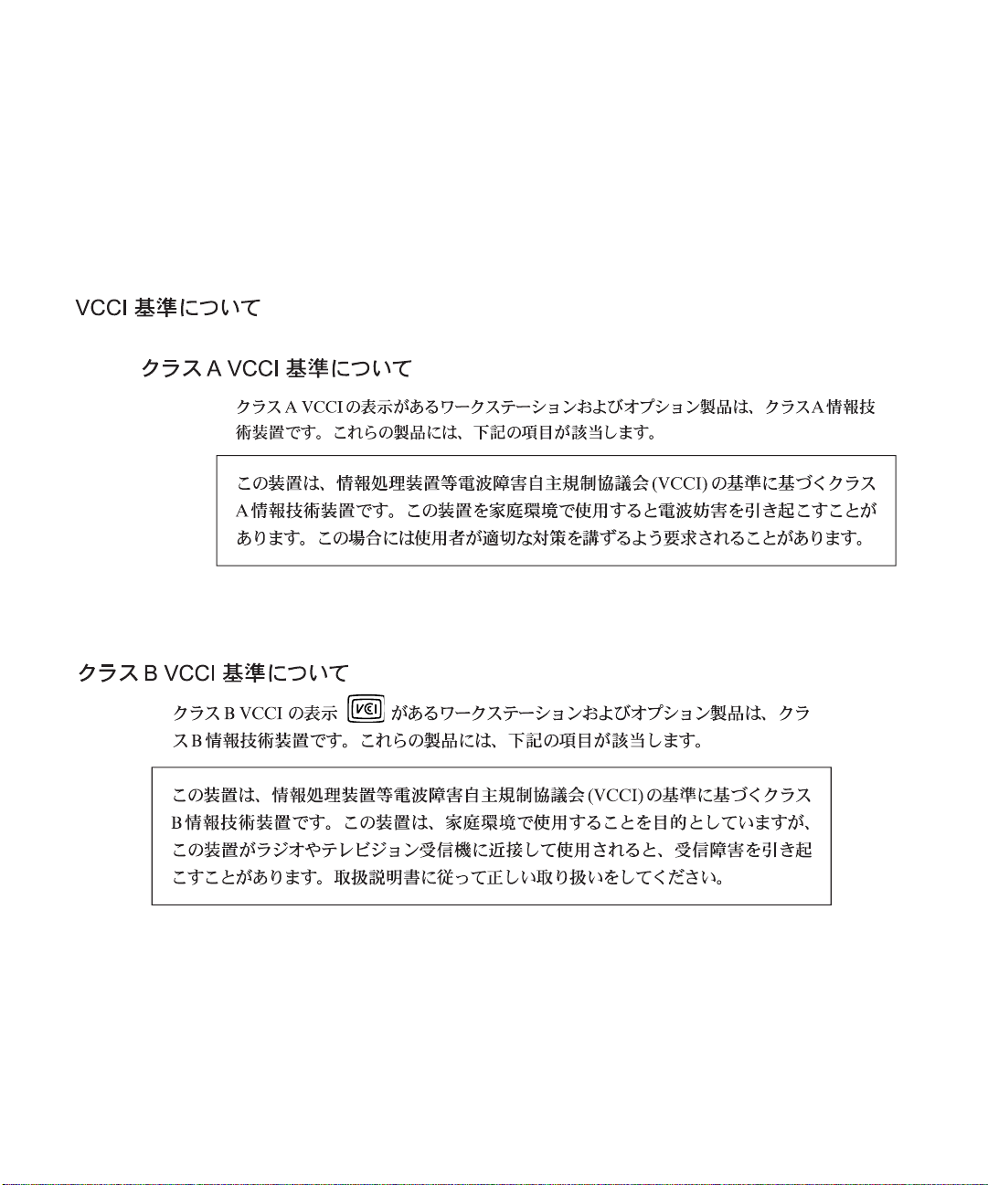
• Voluntary Control Council for Interference (VCCI) — Japan
• Bureau of Standards Metrology and Inspection (BSMI) — Taiwan
Please read the appropriate section that corresponds to the marking on your Sun product before attempting to install the
product.
FCC Class ANotice
This device complies with Part 15 of the FCC Rules. Operation is subject to the following two conditions:
1. This device may not cause harmful interference.
2. This device must accept any interference received, including interference that may cause undesired operation.
Note: This equipment has been tested and found to comply with the limits for a Class A digital device, pursuant to Part 15 of
the FCC Rules. These limits are designed to provide reasonable protection against harmful interference when the equipment
is operated in a commercial environment. This equipment generates, uses, and can radiate radio frequency energy, and if it is
not installed andused in accordance with theinstructionmanual, it may cause harmfulinterferenceto radio communications.
Operation of thisequipment in a residential areais likely to cause harmfulinterference,in which case the userwillbe required
to correct the interference at his own expense.
Shielded Cables:Connectionsbetween the workstationand peripherals mustbemade using shieldedcables to comply with
FCC radio frequency emission limits. Networking connections can be made using unshielded twisted-pair (UTP) cables.
Modifications: Any modifications made to this device that are not approved by Sun Microsystems, Inc. may void the
authority granted to the user by the FCC to operate this equipment.
FCC Class BNotice
This device complies with Part 15 of the FCC Rules. Operation is subject to the following two conditions:
1. This device may not cause harmful interference.
2. This device must accept any interference received, including interference that may cause undesired operation.
Note: This equipment has been tested and found to comply with the limits for a Class B digital device, pursuant to Part 15 of
the FCC Rules. These limits are designed to provide reasonable protection against harmful interference in a residential
installation. This equipment generates, uses and can radiate radio frequency energy and, if not installed and used in
accordance with the instructions, may cause harmful interference to radio communications. However, there is no guarantee
that interference will not occur in a particular installation. If this equipment does cause harmful interference to radio or
television reception,which can be determined byturningthe equipment off andon,the user is encouraged totry to correct the
interference by one or more of the following measures:
• Reorient or relocate the receiving antenna.
• Increase the separation between the equipment and receiver.
• Connect the equipment into an outlet on a circuit different from that to which the receiver is connected.
• Consult the dealer or an experienced radio/television technician for help.
Shielded Cables: Connections between the workstation and peripherals must be made using shielded cables in order to
maintain compliance with FCC radio frequency emission limits. Networking connections can be made using unshielded
twisted pair (UTP) cables.
Modifications: Any modifications made to this device that are not approved by Sun Microsystems, Inc. may void the
authority granted to the user by the FCC to operate this equipment.
v
Page 6
ICES-003 Class ANotice -AvisNMB-003, ClasseA
This Class A digital apparatus complies with Canadian ICES-003.
Cet appareil numérique de la classe A est conforme à la norme NMB-003 du Canada.
ICES-003 Class BNotice -AvisNMB-003, ClasseB
This Class B digital apparatus complies with Canadian ICES-003.
Cet appareil numérique de la classe B est conforme à la norme NMB-003 du Canada.
vi Sun Fire V480 Server Parts Installation and Removal Guide • December 2002
Page 7
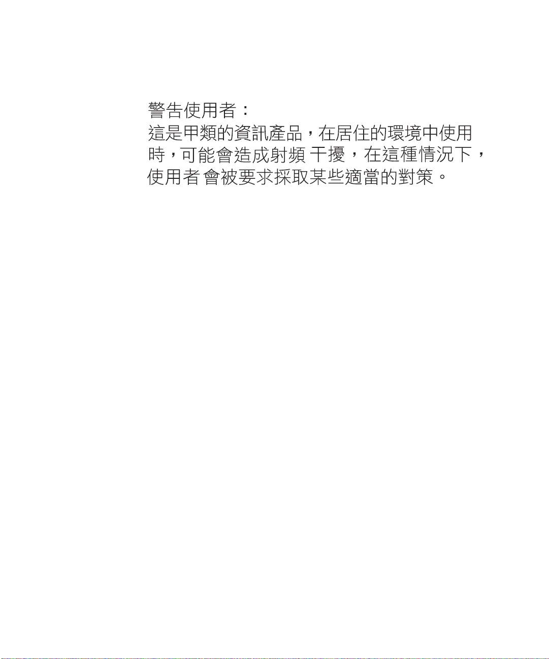
BSMI Class ANotice
The following statement is applicable to products shipped to Taiwan and marked as Class A on the product compliance
label.
Regulatory Compliance Statements vii
Page 8

viii Sun Fire V480 Server Parts Installation and Removal Guide • December 2002
Page 9

Contents
Declaration of Conformity iii
Regulatory Compliance Statements v
Preface xv
1. Identifying Front and Back Panel Features 1
Locating Front Panel Features 2
Locating Back Panel Features 10
2. Preparing to Service the System 17
Tools Required for Installation and Service 18
How to Power On the System 18
How to Power Off the System 22
How to Initiate a Reconfiguration Boot 23
How to Slide the System Out of the Cabinet 25
How to Slide the System Out of a Fully Populated Cabinet 28
How to Slide the System Into the Cabinet 30
How to Remove the System From the Cabinet 32
How to Install the System Into the Cabinet 35
How to Avoid Electrostatic Discharge 39
Contents ix
Page 10

3. Servicing the Front Panel Components 43
About Hot-Swappable and Hot-Pluggable Components 44
How to Remove the Power Supply Access Panel 44
How to Install the Power Supply Access Panel 46
How to Remove a Power Supply 47
How to Install a Power Supply 50
How to Remove a Disk Drive 53
How to Install a Disk Drive 55
How to Remove a Disk Drive Using the Hot-Plug Operation 57
How to Install a Disk Drive Using the Hot-Plug Operation 60
How to Remove Fan Tray 0 63
How to Install Fan Tray 0 65
4. Servicing the CPU/Memory Board and Related Components 69
How to Remove the CPU Access Panel 70
How to Install the CPU Access Panel 72
How to Remove a CPU/Memory Board 74
How to Install a CPU/Memory Board 76
About Memory Modules 79
How to Remove a Memory Module 82
How to Install a Memory Module 85
5. Servicing the PCI Riser Board and Related Components 89
How to Remove the PCI Access Panel 90
How to Install the PCI Access Panel 92
How to Remove Fan Tray 1 93
How to Install Fan Tray 1 95
How to Remove the RSC Card 97
How to Install the RSC Card 99
Contents x
Page 11

How to Remove a PCI Card 101
How to Install a PCI Card 104
How to Install a Sun StorEdge PCI Dual Fibre-Channel Host Adapter Card 107
How to Remove the PCI Riser Board 112
How to Install the PCI Riser Board 115
How to Remove the IDPROM Module 118
How to Install the IDPROM Module 119
6. Servicing Miscellaneous Components 121
How to Remove the FC-AL Backplane 122
How to Install the FC-AL Backplane 124
How to Remove the Removable Media Assembly 125
How to Install the Removable Media Assembly 127
How to Remove the DVD-ROM Drive 129
How to Install the DVD-ROM Drive 130
How to Remove the Centerplane 131
How to Install the Centerplane 134
How to Remove the Power Distribution Board 137
How to Install the Power Distribution Board 140
How to Remove the Media Door Assembly 143
How to Install the Media Door Assembly 147
7. Servicing Cables 151
Cable Connections and Routing 152
How to Remove the FC-AL Power Cable 154
How to Install the FC-AL Power Cable 154
How to Remove the FC-AL Data Cable 156
How to Install the FC-AL Data Cable 156
How to Remove the Removable Media Assembly Cable 158
Contents xi
Page 12

How to Install the Removable Media Assembly Cable 159
How to Remove the System Control Switch/Power Button Cable 161
How to Install the System Control Switch/Power Button Cable 162
How to Remove the Back Panel LED Flex Circuit 163
How to Install the Back Panel LED Flex Circuit 165
How to Remove the Fan Tray 0 Cable 166
How to Install the Fan Tray 0 Cable 168
A. 2-Post Rack Service Requirements 169
Servicing a System Installed in a 2-Post Rack 170
How to Remove the System From an Empty 2-Post Rack 171
How to Install the System Into an Empty 2-Post Rack 173
How to Remove the System From a Populated 2-Post Rack 175
How to Install the System Into a Populated 2-Post Rack 177
B. Connector Pinouts 181
Serial Port Connector 182
USB Connector 183
Twisted-Pair Ethernet Connector 184
RSC Ethernet Connector 185
RSC Modem Connector 186
RSC Serial Connector 187
FC-AL Port HSSDC Connector 188
xii Sun Fire V480 Server Parts Installation and Removal Guide • December 2002
Page 13

C. System Specifications 189
Physical Specifications 189
Electrical Specifications 190
Environmental Specifications 191
Agency Compliance Specifications 192
Clearance and Service Access Specifications 192
D. Safety Precautions 193
E. Board Connector Locations 205
PCI Riser Board Connectors 206
FC-AL Backplane Connectors 206
Centerplane Connectors 207
RSC Connectors 208
F. Illustrated Parts Breakdown 209
Chassis Doors and Access Panels 210
CPU-Side Components 211
PCI-Side Components 212
Front Panel Components 213
Miscellaneous Components 214
System Cables 215
Index 217
Contents xiii
Page 14

xiv Sun Fire V480 Server Parts Installation and Removal Guide • December 2002
Page 15

Preface
The Sun Fire V480 Server Parts Installation and Removal Guide, which includes detailed
service procedures for the Sun Fire
technicians, system administrators, qualified Sun
computer system end users who have experience removing and installing server
hardware.
For information about the Sun Fire V480 server and detailed instructions for
installing, configuring, and administering the server and for diagnosing problems
with the server, see your Sun Fire V480 Server Administration Guide.
This book does not cover mounting the server in a cabinet or 2-post rack. For those
instructions, see the Sun Fire V480 Server Setup and Rackmounting Guide.
Rackmounting instructions are also printed on labels on the server chassis itself.
TM
V480 server, is intended to be used by
TM
service providers, and advanced
Before You Read This Book
Follow the instructions for mounting the server in a cabinet or 2-post rack before
continuing with the installation and configuration instructions in this manual.
Note – This book does not contain troubleshooting or diagnostics information. For
troubleshooting and diagnostics, see your Sun Fire V480 Server Administration Guide.
xv
Page 16

How This Book Is Organized
The procedures in this book are organized as follows:
■ Before You Begin—This section lists the procedures that you must complete
before proceeding to the next section. Complete these prerequisite procedures in
the sequence in which they are printed.
■ What to Do—This section contains the current procedure. Complete the steps in
the sequence in which they are printed, paying special attention to notes and
cautions.
■ What Next—This section contains the procedures you must complete to return
the system to operation. Complete these procedures in the sequence in which they
are printed.
This book contains the following chapters and appendixes:
■ Chapter 1 illustrates the front panel controls and LED indicators.
■ Chapter 2 contains procedures for powering on and powering off the system. In
addition, it describes how to prepare the system for service, including the tools
required, and how to avoid electrostatic discharge.
■ Chapter 3 contains procedures for servicing components on the front panel,
including disk drives and power supplies.
■ Chapter 4 contains procedures for servicing the CPU-side components, including
installing memory.
■ Chapter 5 contains procedures for servicing the PCI riser board and associated
components, including PCI cards and the RSC card.
■ Chapter 6 contains procedures for servicing the centerplane, FC-AL backplane,
removable media assembly, and power distribution board.
■ Chapter 7 contains procedures for servicing cables, including how to route cables
in the system.
■ Appendix A describes service procedures for a system installed in a 2-post rack.
■ Appendix B is a reference for connector pinouts.
■ Appendix C lists physical and environmental specifications.
■ Appendix D contains safety information.
■ Appendix E is a reference for board connectors.
■ Appendix F contains an illustrated parts breakdown, as well as a reference for
field-replaceable unit (FRU) numbers.
xvi Sun Fire V480 Server Parts Installation and Removal Guide • December 2002
Page 17

Using UNIX Commands
This document describes how to shut down the system, and how to boot the system.
For more detailed information about performing system administration tasks, see
one or more of the following:
■ Solaris Handbook for Sun Peripherals
■ AnswerBook2™ online documentation for the Solaris™ operating environment
■ Other software documentation that you received with your system
Typographic Conventions
Typeface Meaning Examples
AaBbCc123 The names of commands, files, and
directories; on-screen computer
output
AaBbCc123
AaBbCc123 Book titles, new words or terms,
What you type, when contrasted
with on-screen computer output
words to be emphasized
Command-line variable; replace
with a real name or value
Edit your.login file.
Use ls -a to list all files.
% You have mail.
% su
Password:
Read Chapter 6 in the User’s Guide.
These are called class options.
You must be superuser to do this.
To delete a file, type rm filename.
Preface xvii
Page 18

Shell Prompts
Shell Prompt
C shell machine-name%
C shell superuser machine-name#
Bourne shell and Korn shell $
Bourne shell and Korn shell superuser #
Related Documentation
The following table describes the documentation shipped with the Sun Fire V480
server.
Application Title Part Number Format
Rack installation Sun Fire V480 Server Setup and
Rackmounting Guide
Service Sun Fire V480 Server Parts
Installation and Removal Guide
Administration,
configuration, diagnostics
and troubleshooting
Sun Fire V480 Server
Administration Guide
816-0902 Printed book
816-0907 PDF, HTML
816-0904 Printed book,
PDF, HTML
xviii Sun Fire V480 Server Parts Installation and Removal Guide • December 2002
Page 19

Accessing Sun Documentation Online
A broad selection of Sun system documentation is located at:
http://www.sun.com/products-n-solutions/hardware/docs
A complete set of Solaris documentation and many other titles are located at:
http://docs.sun.com
Sun Welcomes Your Comments
Sun is interested in improving its documentation and welcomes your comments and
suggestions. You can email your comments to Sun at:
docfeedback@sun.com
Please include the part number (816-0907-12) of your document in the subject line of
your email.
Preface xix
Page 20

xx Sun Fire V480 Server Parts Installation and Removal Guide • December 2002
Page 21

CHAPTER
1
Identifying Front and Back Panel Features
This chapter contains the following sections:
■ “Locating Front Panel Features” on page 2
■ “Locating Back Panel Features” on page 10
For background information about the Sun Fire V480 server and detailed
instructions for installing, configuring, and administering the server and for
diagnosing problems with the server, see your Sun Fire V480 Server Administration
Guide.
1
Page 22
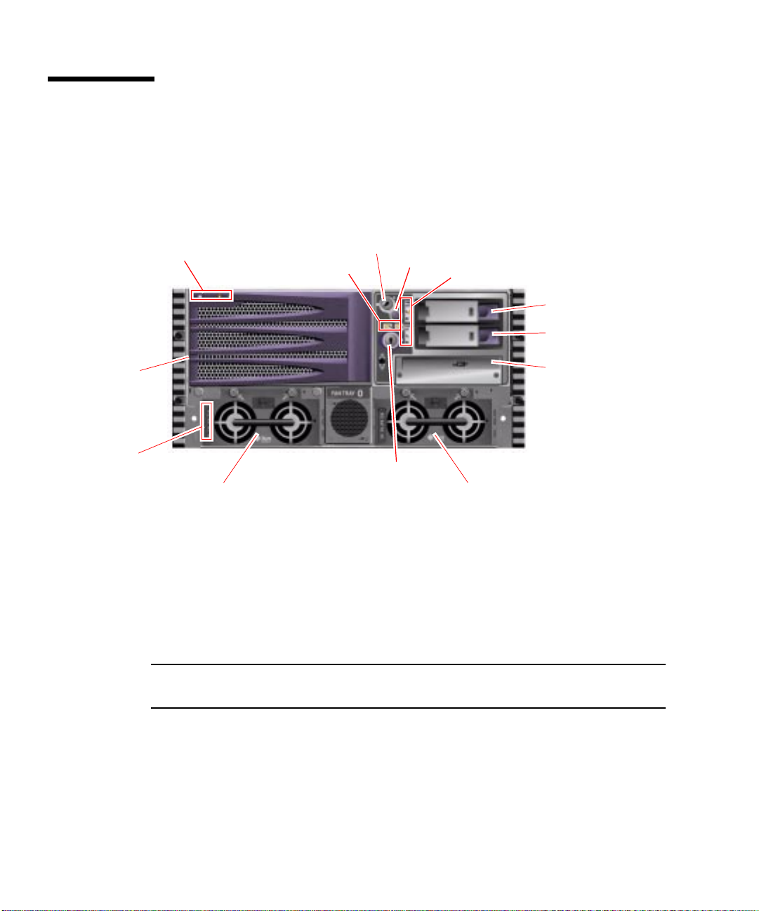
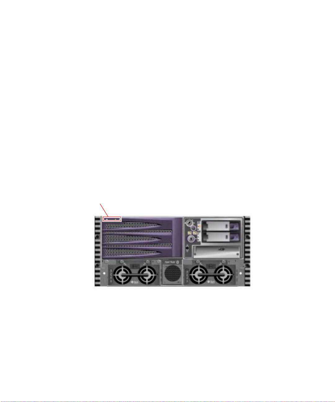
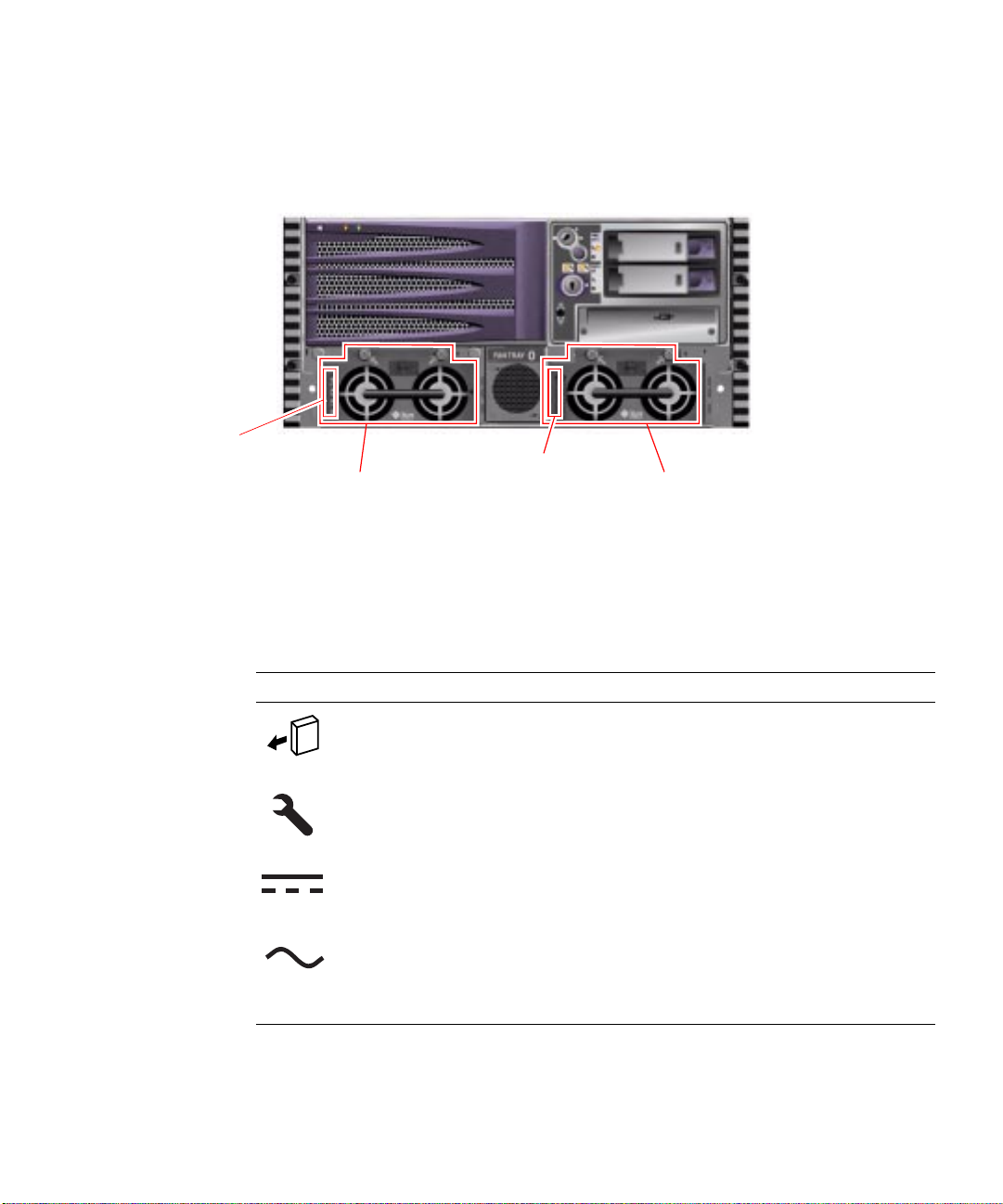
Locating Front Panel Features
The illustration below shows the system features that you can access from the front
panel. In the illustration, the media door and power supply access panel are
removed.
System status LEDs
Fan Tray 0
Power supply status LEDs
Power Supply 0
For information about front panel controls and LEDs, see “Front Panel LEDs” on
page 3.
Two locks control access to the system. The front panel security lock controls access
to all front panel components, including the system control switch, Power button,
disk drives, power supplies, and Fan Tray 0. The top panel lock controls access to
both the CPU access panel and the PCI access panel, and all internal components.
These two locks operate independently.
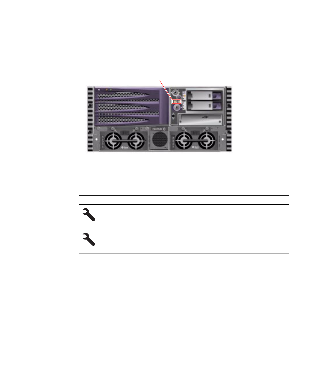
System control switch
Fan tray fault LEDs
Security lock
Power button
Disk drive status LEDs
Disk Drive 1
Disk Drive 0
DVD-ROM drive
Power Supply 1
Note – The same key operates the security lock, system control switch, and system
top panel lock.
The standard system is configured with two power supplies, which are accessible
from the front of the system. See “Front Panel LEDs” on page 3 for additional
details.
2 Sun Fire V480 Server Parts Installation and Removal Guide • December 2002
Page 23
Front Panel LEDs
Several front panel LEDs provide general system status, alert you to system
problems, and help you to determine the location of system faults.
During system startup, LEDs are individually toggled on and off to verify that each
one is working correctly. Other LEDs located on the front of the system work in
conjunction with specific fault LED icons. For example, a fault in the disk subsystem
illuminates the disk drive Fault LED next to the affected disk drive. Since all front
panel status LEDs are powered by the system’s 5-volt standby power source, fault
LEDs remain lit for any fault condition that results in a system shutdown.
System Status LEDs
At the top left of the system as you look at its front are three system status LEDs.
The Power/OK LED and the system Fault LED provide a snapshot of the overall
system status. The Locator LED helps you to quickly locate a specific system even
though it may be one of dozens or even scores of systems in a room. The Locator
LED is at the far left in the cluster, and is lit by command from the administrator.
System status LEDs
Each system status LED has a corresponding LED on the back panel.
Chapter 1 Identifying Front and Back Panel Features 3
Page 24
Listed from left to right, the system status LEDs operate as described in the
following table.
TABLE1-1 System Status LEDs
Icon Name Description
Locator This white LED is lit by Solaris command or by Remote
System Control (RSC) and Sun Management Center (Sun MC)
commands to help locate the system. See the Sun Fire V480
Server Administration Guide for information about turning on
the Locator LED.
Fault This amber LED lights steadily when a system fault is
detected. For example, the system Fault LED lights when a
fault occurs in a power supply, disk drive, or cooling fan.
In addition to the system Fault LED, other fault LEDs may also
be lit, depending on the nature of the fault. If the system Fault
LED is lit, check the status of other fault LEDs on the front
panel to determine the nature of the fault.
During the boot process, this LED flashes for approximately
three seconds. If you press the Power button twice within the
three seconds, the system will come up with factory-set Safe
mode IDPROM variable settings, returning the system to the
ok firmware prompt. See your Sun Fire V480 Server
Administration Guide for more information.
See your Sun Fire V480 Server Administration Guide for
information about troubleshooting your server.
Power/OK This green LED lights continuously when the system power is
on.
4 Sun Fire V480 Server Parts Installation and Removal Guide • December 2002
Page 25
Fan Tray Fault LEDs
Each fan tray has a corresponding fault LED, located below the system control
switch.
Fan tray fault LEDs
Listed from left to right, the fan tray fault LEDs operate as described in the following
table.
TABLE1-2 Fan Tray Fault LEDs
Icon Name Description
FT 0 Fault This amber LED lights to indicate that the system hardware or
system software has detected a fault in Fan Tray 0 (CPU fan
tray).
FT 1 Fault This amber LED lights to indicate that the system hardware or
system software has detected a fault in Fan Tray 1 (PCI fan
tray).
Chapter 1 Identifying Front and Back Panel Features 5
Page 26
Disk Drive Status LEDs
Each disk drive has its own status LEDs.
Disk drive LEDs
Listed from top to bottom, the disk drive LEDs operate as described in the following
table.
TABLE1-3 Disk Drive LEDs
Icon Name Description
OK-to-Remove This blue LED lights when the disk drive has been taken
offline and is ready to remove.
Fault This amber LED lights to indicate that the system hardware or
system software has detected a disk drive fault. If a disk drive
Fault LED is lit, the system Fault LED will also be lit.
Activity This green LED is lit when the system is on and a disk drive is
present, and flashes when the disk drive is reading or writing
data.
6 Sun Fire V480 Server Parts Installation and Removal Guide • December 2002
Page 27
Power Supply LEDs
Each power supply has its own status LEDs.
Power Supply 0 status LEDs
Power Supply 0
Each power supply LED has a corresponding LED on the back panel.
Listed from top to bottom, the power supply LEDs operate as described in the
following table.
TABLE1-4 Power Supply LEDs
Icon Name Description
OK-to-Remove This blue LED lights when the power supply is OK to
Fault Thisamber LED lights to indicate a power supply fault. If a
DC Present This green LED is lit when DC output power is available.
AC Present This green LED is lit when AC input power is present. This
Power Supply 1 status LEDs
Power Supply 1
remove.
power supply Fault LED is lit, the system Fault LED will
also be lit.
LED is lit if the corresponding AC cable is plugged in to a
power source and the power supply is functioning
correctly, regardless of system power status.
Chapter 1 Identifying Front and Back Panel Features 7
Page 28
Power Button
The system Power button is recessed to prevent accidentally turning the system on
or off. The ability of the Power button to turn the system on or off is controlled by
the system control switch.
If the operating system is running, pressing and releasing the Power button initiates
a graceful software system shutdown. Pressing and holding in the Power button for
five seconds causes an immediate hardware shutdown.
Caution – Whenever possible, you should use the graceful shutdown method.
Forcing an immediate hardware shutdown may cause disk drive corruption and loss
of data.
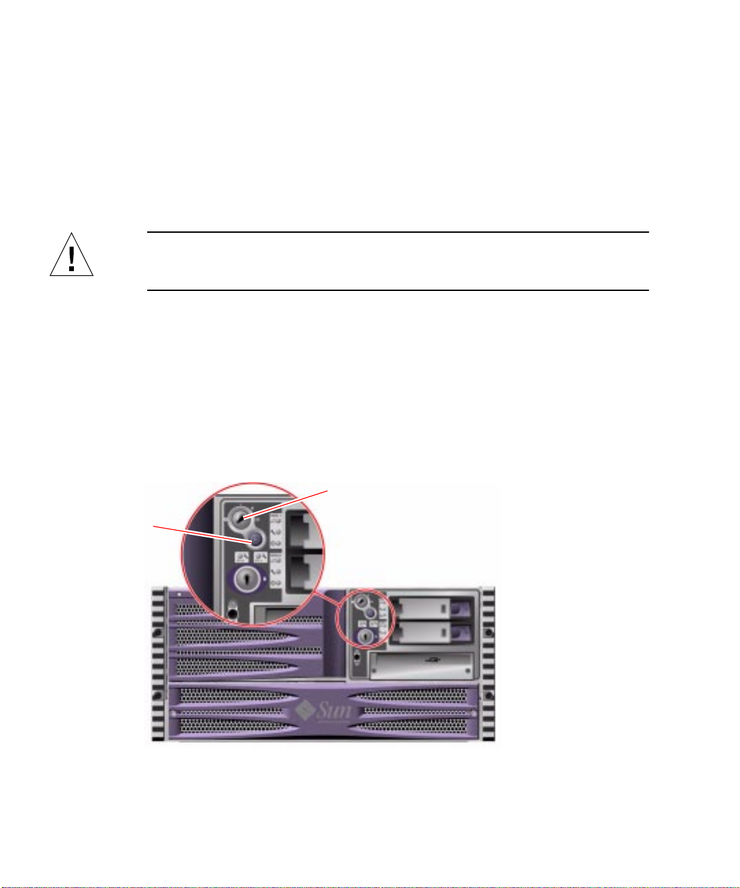
System Control Switch
The four-position system control switch on the system’s status and control panel
controls the power-on modes of the system and prevents unauthorized users from
powering off the system or reprogramming system firmware. In the following
illustration, the system control switch is in the Locked position.
System control switch
Power button
8 Sun Fire V480 Server Parts Installation and Removal Guide • December 2002
Page 29
The following table describes the function of each system control switch setting.
TABLE1-5 System Control Switch Settings
Icon Position Description
Normal This setting enables the system Power button to power the
system on or off.
Locked This setting disables the system Power button to prevent
unauthorized users from powering the system on or off. It also
disables the keyboard Stop-A command, terminal Break key
command, and ~# tip window command, preventing users
from suspending system operation to access the system ok
prompt.
The Locked setting, used for normal day-to-day operations,
also prevents unauthorized programming of the system Boot
PROM.
Diagnostics This setting forces the power-on self-test (POST) and
OpenBoot
and system resets. The Power button functions the same as
when the system control switch is in the Normal position.
Forced Off This setting forces the system to power off immediately and to
enter 5-volt standby mode. It also disables the system Power
button. You may want to use this setting when AC power is
interrupted and you do not want the system to restart
automatically when power is restored. With the system control
switch in any other position, if the system were running prior
to losing power, it restarts automatically once power is
restored.
™ Diagnostics tests to run during system startup
The Forced Off setting also prevents an RSC console from
restarting the system. However, the RSC card continues to
operate using the system’s 5-volt standby power.
Chapter 1 Identifying Front and Back Panel Features 9
Page 30
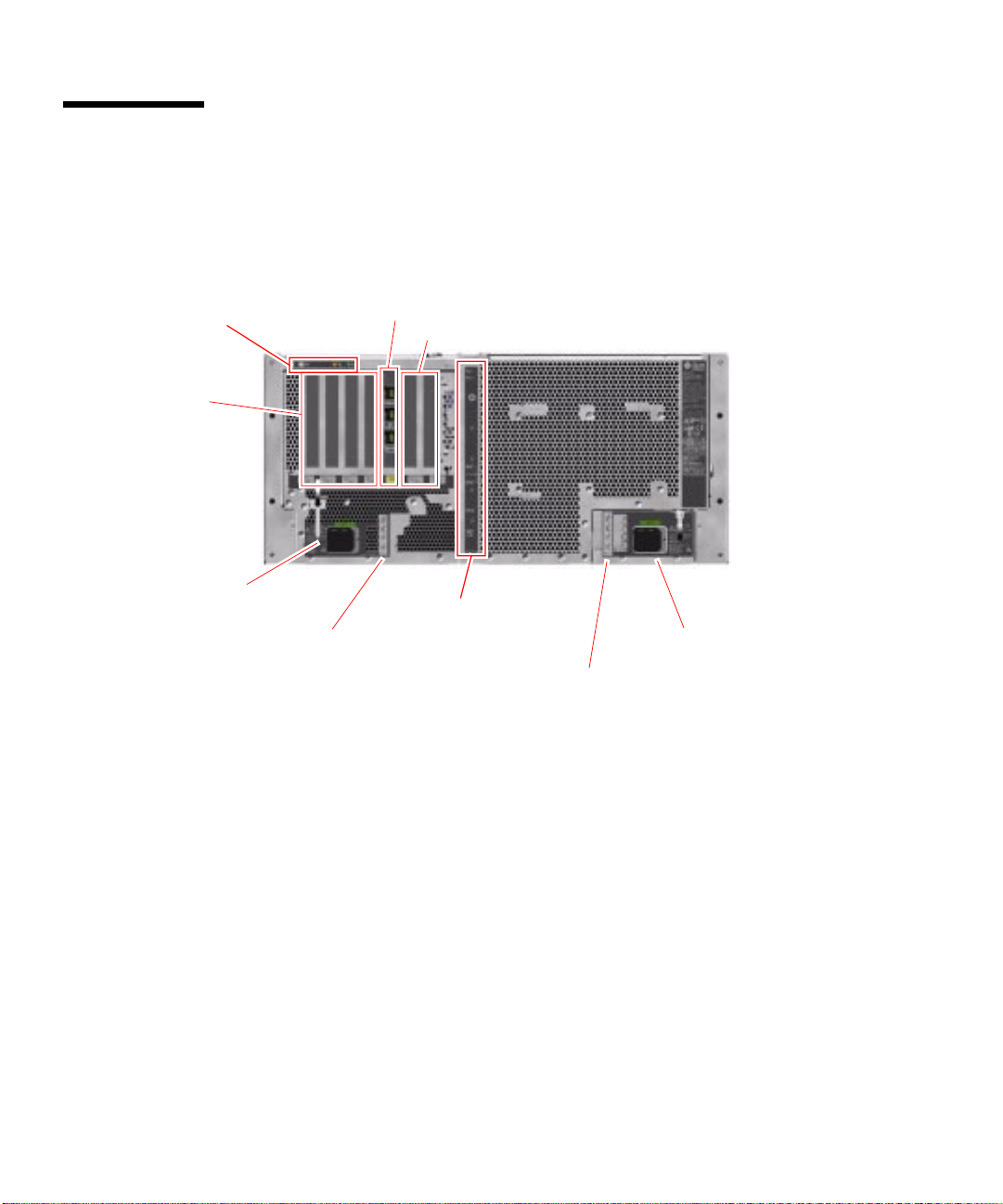
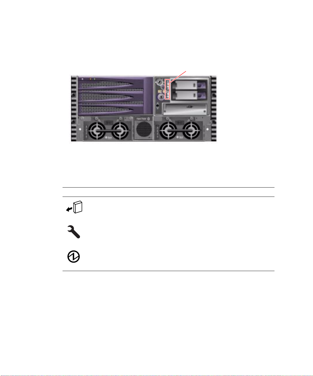
Locating Back Panel Features
The illustration below shows the system features that are accessible from the back
panel.
System status LEDs
33-MHz PCI slots
Power Supply 1 AC inlet
Power Supply 1 status LEDs
RSC card
66-MHz PCI slots
External I/O ports
Power Supply 0 AC inlet
PowerSupply 0 status LEDs
10 Sun Fire V480 Server Parts Installation and Removal Guide • December 2002
Page 31

Back Panel LEDs
System Status LEDs
The back panel system status LEDs consist of the Power/OK LED, the system Fault
LED, and the Locator LED. These LEDs are located in the top-left corner of the back
panel, and operate as described in
System status LEDs
TABLE 1-1.
Ethernet Connection LEDs
A set of Ethernet connection LEDs is located in each Ethernet port. The Ethernet
connection LEDs operate as described in the following table.
TABLE1-6 Ethernet Connection LEDs
Name Description
Link Up This green LED is lit when an Ethernet connection is present.
Activity This amber LED flashes whenever an Ethernet connection is
active, that is, transmitting or receiving data.
Chapter 1 Identifying Front and Back Panel Features 11
Page 32

Power Supply LEDs
Each power supply has a corresponding set of four LEDs.
Power Supply 1 AC inlet
Power Supply 1 status LEDs
These LEDs operate as described in
PowerSupply 0 status LEDs
TABLE 1-4.
Power Supply 0 AC inlet
Note – Power Supply 1 LEDs are located on the left, and Power Supply 0 LEDs are
on the right. This is opposite to the arrangement of the power supply status LEDs on
the front panel.
12 Sun Fire V480 Server Parts Installation and Removal Guide • December 2002
Page 33

33-MHz PCI slots
Back Panel Slots and Ports
PCI Slots
The Sun Fire V480 server has four 33-MHz PCI slots and two 66-MHz slots; these are
labeled on the back panel. The Remote System Control (RSC) card is located between
the low-speed and high-speed slots.
RSC card
66-MHz PCI slots
Chapter 1 Identifying Front and Back Panel Features 13
Page 34

External Ports
The Sun Fire V480 server has six external data ports on the back panel.
USB ports (2)
Ethernet ports
Serial port
FC-AL port
These external ports are described in
TABLE1-7 Back Panel External Ports
Icon Description
Universal Serial Bus (USB) ports. The Sun Fire V480 has two USB ports.
Ethernet ports. The system has two Ethernet ports.
SERIAL
Serial port. The system has one serial port on the back panel, which uses an
RJ-45 connector.
Fibre-Channel Arbitrated-Loop (FC-AL) external loop.
TABLE 1-7.
14 Sun Fire V480 Server Parts Installation and Removal Guide • December 2002
Page 35

RSC Ports
The Remote System Control (RSC) card has three connectors.
RSC card
These RSC connectors are described in
TABLE1-8 RSC External Ports
Icon Description
SERIAL
Serial (RJ-45) port
Modem (RJ-11) port
Ethernet port
TABLE 1-8.
Chapter 1 Identifying Front and Back Panel Features 15
Page 36

16 Sun Fire V480 Server Parts Installation and Removal Guide • December 2002
Page 37

CHAPTER
2
Preparing to Service the System
This chapter describes service procedures. It contains the following sections:
■ “Tools Required for Installation and Service” on page 18
■ “How to Power On the System” on page 18
■ “How to Power Off the System” on page 22
■ “How to Initiate a Reconfiguration Boot” on page 23
■ “How to Slide the System Out of the Cabinet” on page 25
■ “How to Slide the System Out of a Fully Populated Cabinet” on page 28
■ “How to Slide the System Into the Cabinet” on page 30
■ “How to Remove the System From the Cabinet” on page 32
■ “How to Install the System Into the Cabinet” on page 35
■ “How to Avoid Electrostatic Discharge” on page 39
Note – If you are servicing a system installed in a 2-post rack, see Appendix A.
Guidelines
Be sure to keep the following guidelines in mind:
■ Except for removing and installing power supplies and disk drives, this system
must be serviced by qualified service providers.
■ Power supplies are hot-swappable. For information about hot-swapping, see
“About Hot-Swappable and Hot-Pluggable Components” on page 44.
■ Internal disk drives are hot-pluggable. For information about hot-plugging, see
“About Hot-Swappable and Hot-Pluggable Components” on page 44.
■ For servicing any other parts internal to the system, you must first power off the
system. See “How to Power Off the System” on page 22.
17
Page 38

Tools Required for Installation and Service
The following tools are required to service the system:
■ Screwdriver, standard Phillips No. 1
■ Screwdriver, standard Phillips No. 2
■ Screwdriver, long Phillips No. 2 (shaft at least 8 inches long)
■ Needle-nose pliers
■ Adjustable wrench
■ Electrostatic discharge (ESD) mat, Sun part number 250-1088, or equivalent
■ Grounding wrist or foot strap
The latter two items help protect the server against damage due to electrostatic
discharge. For more information, see “How to Avoid Electrostatic Discharge” on
page 39.
How to Power On the System
Before You Begin
Do not use this power-on procedure if you have just added any new internal option
or external storage device, or if you have removed a storage device without
replacing it. To power on the system under those circumstances, see:
■ “How to Initiate a Reconfiguration Boot” on page 23
Caution – Never move the system when the system power is on. Movement can
cause catastrophic disk drive failure. Always power off the system before moving it.
Caution – Before you power on the system, make sure that all access panels are
properly installed.
18 Sun Fire V480 Server Parts Installation and Removal Guide • December 2002
Page 39

What to Do
1. Turn on power to any peripherals and external storage devices.
Read the documentation supplied with the device for specific instructions.
2. Turn on power to the ASCII terminal or local graphics terminal, if present.
3. Open the media door.
Use the system key to unlock the media door.
Media door
Chapter 2 Preparing to Service the System 19
Page 40

4. Insert the system key into the system control switch and turn the system control
Normal position
Power button
switch to the Normal or Diagnostics position.
See “Locating Front Panel Features” on page 2 for information about each system
control switch setting.
Diagnostics position
5. Press the Power button that is below the system control switch to power on the
system.
Note – The system may take anywhere from 30 seconds to two minutes before video
is displayed on the system monitor or the ok prompt appears on an attached
terminal. This time depends on the system configuration (number of CPUs, memory
modules, PCI cards) and the level of power-on self-test (POST) and OpenBoot
Diagnostics tests being performed.
20 Sun Fire V480 Server Parts Installation and Removal Guide • December 2002
TM
Page 41

6. Turn the system control switch to the Locked position.
This prevents anyone from accidentally powering off the system.
Locked position
7. Remove the system key from the system control switch and keep it in a secure
place.
What Next
To power off the system, complete this task:
■ “How to Power Off the System” on page 22
Chapter 2 Preparing to Service the System 21
Page 42

How to Power Off the System
Before You Begin
Applications running on the Solaris operating environment can be adversely affected
by a poorly executed system shutdown. Make sure you have gracefully shut down
any applications before powering off the system.
What to Do
1. Notify users that the system will be powered down.
2. Back up the system files and data, if necessary.
3. Ensure that the system control switch is in the Normal or Diagnostics position.
4. Press and release the Power button on the system front panel.
The system begins a graceful software system shutdown.
Note – Pressing and releasing the Power button initiates a graceful software system
shutdown. Pressing and holding in the Power button for five seconds causes an
immediate hardware shutdown. Whenever possible, you should use the graceful
shutdown method. Forcing an immediate hardware shutdown may cause disk drive
corruption and loss of data. Use that method only as a last resort.
5. Wait for the system Power/OK LED to turn off.
6. Turn the system control switch to the Forced Off position.
Caution – Be sure to turn the system control switch to the Forced Off position
before handling any internal components. Otherwise, it is possible for an operator at
a Remote System Control (RSC) console to restart the system while you are working
inside it. The Forced Off position is the only system control switch position that
prevents an RSC console from restarting the system.
7. Remove the system key from the system control switch and keep it in a secure
place.
22 Sun Fire V480 Server Parts Installation and Removal Guide • December 2002
Page 43

What Next
Continue with your parts removal and installation, as needed.
How to Initiate a Reconfiguration Boot
After installing any new internal option or external storage device, you must
perform a reconfiguration boot so that the operating system is able to recognize the
newly installed device(s). In addition, if you remove any device and do not install a
replacement device prior to rebooting the system, you must perform a
reconfiguration boot in order for the operating system to recognize the configuration
change. This requirement also applies to any component that is connected to the
system’s I
supplies.
This requirement does not apply to any component that is:
■ Installed or removed as part of a hot-plug or hot-swap operation
■ Installed or removed before the operating system is installed
■ Installed as an identical replacement for a component that is already recognized
by the operating system
2
C bus, including memory modules, CPU/Memory boards, and power
Before You Begin
Caution – Before you power on the system, make sure that the system doors and all
panels are properly installed.
You need a system ASCII terminal, local graphics terminal, or a tip connection to
the Sun Fire V480 server in order to issue software commands. See your Sun Fire
V480 Server Administration Guide.
What to Do
1. Turn on power to any peripherals and external storage devices.
Read the documentation supplied with the device for specific instructions.
2. Turn on power to the ASCII terminal or local graphics terminal.
Chapter 2 Preparing to Service the System 23
Page 44

3. Insert the system key into the system control switch and turn the system control
switch to the Diagnostics position.
Use the Diagnostics position to run POST and OpenBoot Diagnostics tests to verify
that the system functions correctly with the new part(s) you just installed. See
“Locating Front Panel Features” on page 2 for information about system control
switch settings.
4. Press the Power button below the system control switch to power on the system.
5. When the system banner is displayed on the system console, immediately abort
the boot process to access the system ok prompt.
The system banner contains the Ethernet address and host ID. To abort the boot
process, use one of the following methods:
■ Hold down the Stop key and press A on a Sun keyboard.
■ Press the Break key on the terminal keyboard.
■ Type ~# in a tip window.
Note – The system may take anywhere from 30 seconds to two minutes before the
system banner appears. This time depends on the system configuration (number of
CPUs, memory modules, PCI cards) and the level of power-on self-test (POST) and
OpenBoot Diagnostics tests being performed.
6. At the ok prompt, type:
ok env-on
Environmental monitor is ON
ok boot -r
The env-on command reenables the OpenBoot environmental monitor, which may
have been disabled as a result of the abort key sequence. Booting the system with
the boot -r command rebuilds the device tree for the system, incorporating any
newly installed options so that the operating system will recognize them.
7. Turn the system control switch to the Locked position, remove the key, and keep it
in a secure place.
This prevents anyone from accidentally powering off the system.
What Next
The system’s front panel LED indicators provide power-on status information.
For more information about the system LEDs, see:
■ “Front Panel LEDs” on page 3
24 Sun Fire V480 Server Parts Installation and Removal Guide • December 2002
Page 45

If your system encounters a problem during system startup, and the system control
switch is in the Normal position, try restarting the system in Diagnostics mode to
determine the source of the problem. Turn the system control switch to the
Diagnostics position and power cycle the system. See:
■ “How to Power On the System” on page 18
For information about system troubleshooting and diagnostics, see your Sun Fire
V480 Server Administration Guide.
How to Slide the System Out of the Cabinet
This procedure describes placing the system in position for service by sliding it out
of the cabinet without removing it from the rack. All service procedures except
removing and replacing the centerplane and power distribution board can be
performed while the system is still attached to the cabinet.
Note – Sliding the system out of the cabinet is not required for servicing disk drives,
power supplies, or Fan Tray 0.
Before You Begin
Caution – Unless the cabinet is bolted to the floor, you must extend the cabinet’s
anti-tip legs and adjust their stabilizing feet to the floor. You must level and secure
the cabinet to provide a safe working environment. See “Tools Required for
Installation and Service” on page 18 for useful tools required for this procedure.
What to Do
1. Be sure the cabinet is stabilized so that the cabinet cannot move or tip forward.
If there are feet beneath the cabinet to prevent it from rolling, be sure the feet are
fully extended downward to the floor.
Stabilize the cabinet using the stabilizing mechanisms provided with the cabinet.
See the instructions provided with the cabinet.
Chapter 2 Preparing to Service the System 25
Page 46

2. Open (or remove) the front and back cabinet doors.
3. Disconnect all external cables attached to the back panel of the system.
Caution – Do not disconnect the power cord(s) from the system power inlet(s)
unless you are installing or replacing the power distribution board, the centerplane,
the PCI riser board, or the Remote System Control (RSC) card. The power cord
grounds the system.
4. Loosen the four captive screws that secure the system to the left and right vertical
rails at the front of the rack.
Use a Phillips No. 2 screwdriver to loosen the captive screws, which are in recessed
access holes in the decorative panels affixed to the system’s front panel.
26 Sun Fire V480 Server Parts Installation and Removal Guide • December 2002
Page 47

5. Slide the system chassis evenly out of the cabinet until the inner glides stop in the
slide.
Pull the system smoothly out of the enclosure. Continue pulling the system until the
back of the chassis clears the enclosure and you hear the flat spring catches in the
glides engage with an audible clicking sound. The system is then fully extended and
secure.
What Next
To slide the system into the cabinet, see:
■ “How to Slide the System Into the Cabinet” on page 30
Chapter 2 Preparing to Service the System 27
Page 48

How to Slide the System Out of a Fully Populated Cabinet
This procedure describes placing the system in position for service by sliding it out
of a fully populated cabinet without removing it from the rack. This procedure also
describes how to remove the system from the cabinet. All service procedures except
removing and replacing the centerplane and power distribution board can be
performed while the system is still attached to the cabinet.
Note – Sliding the system out of the cabinet is not required for servicing disk drives,
power supplies, or Fan Tray 0.
Before You Begin
Caution – Unless the cabinet is bolted to the floor, you must extend the cabinet’s
anti-tip legs and adjust their stabilizing feet to the floor. You must level and secure
the cabinet to provide a safe working environment. See “Tools Required for
Installation and Service” on page 18 for useful tools required for this procedure.
What to Do
1. Be sure the cabinet is stabilized so that the cabinet cannot move or tip forward.
If there are feet beneath the cabinet to prevent it from rolling, be sure the feet are
fully extended downward to the floor.
Stabilize the cabinet using the stabilizing mechanisms provided with the cabinet.
See the instructions provided with the cabinet.
2. Open (or remove) the front and back cabinet doors.
3. Disconnect all external cables attached to the back panel of the system.
28 Sun Fire V480 Server Parts Installation and Removal Guide • December 2002
Page 49

Caution – Do not disconnect the power cord(s) from the system power inlet(s)
unless you are installing or replacing the power distribution board, the centerplane,
the PCI riser board, or the Remote System Control (RSC) card. The power cord
grounds the system.
4. Remove the power supply access panel.
See “How to Remove the Power Supply Access Panel” on page 44.
5. Make sure that the power supply mounting screws are fully tightened.
Power supply mounting screws
6. Loosen the four captive screws that secure the system to the left and right vertical
rails at the front of the rack.
Use a Phillips No. 2 screwdriver to loosen the captive screws, which are in recessed
access holes in the decorative panels affixed to the system’s front panel.
7. Slide the system chassis evenly out of the cabinet until the inner glides stop in the
slide.
Pull the system smoothly out of the enclosure, holding the system by the power
supply handles. Continue pulling the system until the back of the chassis clears the
enclosure and you hear the flat spring catches in the glides engage with an audible
clicking sound. The system is then fully extended and secure.
Note – If you need to remove the server completely from the cabinet, see Step 5
through Step 9 in “How to Remove the System From the Cabinet” on page 32.
Chapter 2 Preparing to Service the System 29
Page 50

What Next
Before sliding the system back into the cabinet, you must install the power supply
access panel. See:
■ “How to Install the Power Supply Access Panel” on page 46
To slide the system into the cabinet, see:
■ “How to Slide the System Into the Cabinet” on page 30
How to Slide the System Into the Cabinet
Before You Begin
If you have been working inside the system, replace all access panels. See the
following sections for more information:
■ “How to Install the Power Supply Access Panel” on page 46
■ “How to Install the CPU Access Panel” on page 72
■ “How to Install the PCI Access Panel” on page 92
30 Sun Fire V480 Server Parts Installation and Removal Guide • December 2002
Page 51

What to Do
1. Slide the system chassis evenly into the cabinet until the system comes to a
complete stop.
2. Tighten the four captive screws securing the system to the left and right vertical
rails at the front of the rack.
Use a Phillips No. 2 screwdriver to tighten the four captive screws, which are in
recessed access holes in the decorative panels affixed to the system’s front panel.
3. Connect all external cables that were attached to the back panel of the system.
Examine each disconnected cable for information indicating the cable’s origin and its
terminating connection.
4. Replace, close, and lock the cabinet doors, as appropriate.
What Next
To power on the system, see:
■ “How to Power On the System” on page 18
Chapter 2 Preparing to Service the System 31
Page 52

How to Remove the System From the Cabinet
Sun recommends you remove the system from the cabinet when doing the
following:
■ Removing and installing the centerplane
■ Removing and installing the power distribution board
■ Removing and installing the system control switch/power button cable
You can perform all other procedures while the system is still attached to the rails
extended from the rack. If you want to remove the system from the cabinet for any
other reason, follow the instructions in this section.
Caution – The chassis is heavy. Two persons are required to remove the system
from the cabinet in the following procedure.
Before You Begin
Complete these tasks:
■ Identify a helper to assist you in removing the system.
■ Review the steps in the next section with your helper beforehand and discuss
how to coordinate your efforts to ensure your mutual safety.
■ Assemble the correct tools for the procedure. See “Tools Required for Installation
and Service” on page 18.
■ Power off the system. See “How to Power Off the System” on page 22.
Caution – When completing a two-person procedure, always communicate your
intentions clearly before, during, and after each step to minimize confusion.
32 Sun Fire V480 Server Parts Installation and Removal Guide • December 2002
Page 53

Note – Make sure the ball-bearing runner on each slide assembly is all the way
forward.
What to Do
1. Be sure the cabinet is stabilized so that the cabinet cannot move or tip forward.
If there are feet beneath the cabinet to prevent it from rolling, be sure the feet are
fully extended downward to the floor.
Stabilize the cabinet using the stabilizing mechanisms provided with the cabinet. See
the instructions provided with the cabinet.
2. Open (or remove) the front and back cabinet doors.
3. Disconnect all external cables attached to the back panel of the system.
Caution – Do not disconnect the power cord(s) from the system power inlet(s)
unless you are installing or replacing the system control switch/power button cable,
power distribution board, the centerplane, the PCI riser board, or the Remote System
Control (RSC) card. The power cord grounds the system.
4. Extend the server from the cabinet, and then position one person on each side of
the system, facing the system glides.
When you are both in position, verify that your helper understands what to do with
the system after you release the server and remove it. Also agree on a route to
follow, and visually inspect it for potential safety hazards (for example, cables on the
floor, other people working in the vicinity, and so on).
Chapter 2 Preparing to Service the System 33
Page 54

5. Locate the flat spring catch shown in the following figure.
Each person should visually locate one of the two flat spring catches that release the
system from the rack glide. One catch is attached to each inner glide, as shown in the
following figure.
6. Prepare to remove the system.
Each person should place one hand on the flat spring catch and their other hand
beneath the chassis, palm up, ready to support the weight of the chassis.
Caution – The chassis is heavy. Two persons are required to remove the system
from the cabinet in the following steps.
34 Sun Fire V480 Server Parts Installation and Removal Guide • December 2002
Page 55

7. Simultaneously press in on both flat spring catches to release them, and then slide
the system out of the glides.
Each person presses one spring catch and helps slide the system free of the outer
glide, supporting the weight of the system with both hands as the system slides free
of the rack.
8. Set the system on a workbench or other stable surface.
9. Reattach, close, and lock the cabinet doors as appropriate.
What Next
To place the system into the rack glides, see:
■ “How to Install the System Into the Cabinet” on page 35
How to Install the System Into the Cabinet
This procedure assumes that the slide assemblies are already installed in the rack.
For further information about installing the slide assemblies, see the Sun Fire V480
Server Setup and Rackmounting Guide.
Caution – The chassis is heavy. Two persons are required to place the system into
the rack slide assembly in the following procedure.
Chapter 2 Preparing to Service the System 35
Page 56

Before You Begin
Complete these tasks:
■ Identify a helper to assist you in installing the system.
■ Review the steps in the next section with your helper beforehand and discuss
how to coordinate your efforts to ensure your mutual safety.
■ Assemble the correct tools for the procedure. See “Tools Required for Installation
and Service” on page 18.
Caution – When completing a two-person procedure, always communicate your
intentions clearly before, during, and after each step to minimize confusion.
What to Do
1. Be sure the cabinet is stabilized so that the cabinet cannot move or tip forward.
If there are feet beneath the cabinet to prevent it from rolling, be sure the feet are
fully extended downward to the floor.
Stabilize the cabinet using the stabilizing mechanisms provided with the cabinet. See
the instructions provided with the cabinet.
2. Open (or remove) the cabinet doors.
3. Slide the empty rack slides back into their protective outer glides.
4. Position one person on each side of the system, facing the inner glides on the
system chassis.
Caution – The chassis is heavy. Two persons are required to place the system into
the rack slide assembly.
When you are both in position, verify that your helper understands what to do with
the system after you lift it. Also agree on a route to follow to the cabinet, and
visually inspect the route for potential safety hazards (for example, cables on the
floor, other people working in the vicinity, and so on).
36 Sun Fire V480 Server Parts Installation and Removal Guide • December 2002
Page 57

5. Lift the system and carry it to the front of the cabinet.
Each person should place both hands beneath the chassis and support half the
weight of the system.
6. Insert the system glides into the inner slides of the rack glides.
7. Slide the system smoothly into the rack slides until it is stopped inside the
cabinet.
Chapter 2 Preparing to Service the System 37
Page 58

8. Secure the system to the left and right vertical rails at the front of the rack.
Use a Phillips No. 2 screwdriver to tighten the four captive screws that secure the
system in the cabinet. These screws are in recessed access holes in the decorative
panels affixed to the system’s front panel.
9. Connect all external cables that were attached to the back panel of the system.
Examine each disconnected cable for information indicating the cable’s origin and its
terminating connection.
10. Replace, close, and lock the cabinet doors, as appropriate.
What Next
To power on the system, see:
■ “How to Power On the System” on page 18
38 Sun Fire V480 Server Parts Installation and Removal Guide • December 2002
Page 59

How to Avoid Electrostatic Discharge
Use the following procedure to prevent static damage whenever you are accessing
any of the internal components of the system.
Before You Begin
Complete these tasks:
■ “How to Power Off the System” on page 22
■ “How to Slide the System Out of the Cabinet” on page 25
If you are servicing any internal components, remove the relevant access panel.
Complete the appropriate task(s):
■ “How to Remove the Power Supply Access Panel” on page 44
■ “How to Remove the CPU Access Panel” on page 70
■ “How to Remove the PCI Access Panel” on page 90
You must have the following items:
■ Antistatic wrist or foot strap
■ Antistatic mat
What to Do
Caution – Printed circuit boards and hard disk drives contain electronic
components that are extremely sensitive to static electricity. Ordinary amounts of
static from your clothes or the work environment can destroy components.
Do not touch the components or any metal parts without taking proper antistatic
precautions.
1. Disconnect the AC power cord(s) from power inlet(s) only when performing the
following procedures:
■ Removing and installing the power distribution board
■ Removing and installing the centerplane
■ Removing and installing the PCI riser board
■ Removing and installing the Remote System Control (RSC) card
■ Removing and installing the system control switch/power button cable
The AC power cord provides a discharge path for static electricity, so it should
remain plugged in except when you are servicing the parts noted above.
Chapter 2 Preparing to Service the System 39
Page 60

2. Use an antistatic mat or similar surface.
When performing any installation or service procedure, place static-sensitive parts,
such as boards, cards, and disk drives, on an antistatic surface. The following items
can be used as an antistatic surface:
■ The bag used to wrap a Sun replacement part
■ The shipping container used to package a Sun replacement part
■ Sun electrostatic discharge (ESD) mat, Sun part number 250-1088 (available
through your Sun sales representatives)
■ Disposable ESD mat, shipped with replacement parts or options
3. Use an antistatic wrist strap.
Attach the appropriate end to the system chassis sheet metal and attach the other
end of the strap to your wrist. Refer to the instructions that come with the strap.
Note – Make sure that the wrist strap is in direct contact with the metal on the
chassis.
4. Detach both ends of the strap after you have completed the installation or service
procedure.
40 Sun Fire V480 Server Parts Installation and Removal Guide • December 2002
Bare metal area
Page 61

What Next
To reassemble and power on the system, complete the appropriate task(s):
■ “How to Install the Power Supply Access Panel” on page 46
■ “How to Install the CPU Access Panel” on page 72
■ “How to Install the PCI Access Panel” on page 92
■ “How to Power On the System” on page 18
Chapter 2 Preparing to Service the System 41
Page 62

42 Sun Fire V480 Server Parts Installation and Removal Guide • December 2002
Page 63

CHAPTER
3
Servicing the Front Panel Components
This chapter contains the following sections:
■ “About Hot-Swappable and Hot-Pluggable Components” on page 44
■ “How to Remove the Power Supply Access Panel” on page 44
■ “How to Install the Power Supply Access Panel” on page 46
■ “How to Remove a Power Supply” on page 47
■ “How to Install a Power Supply” on page 50
■ “How to Remove a Disk Drive” on page 53
■ “How to Install a Disk Drive” on page 55
■ “How to Remove a Disk Drive Using the Hot-Plug Operation” on page 57
■ “How to Install a Disk Drive Using the Hot-Plug Operation” on page 60
■ “How to Remove Fan Tray 0” on page 63
■ “How to Install Fan Tray 0” on page 65
Note – To service the system control switch/power button cable assembly, see
Chapter 7.
43
Page 64

About Hot-Swappable and
Hot-Pluggable Components
The power supplies are hot-swappable; you can remove and replace a power supply
while the system is running, as long as the other power supply is working properly.
For more information, see the following:
■ “How to Remove a Power Supply” on page 47
■ “How to Install a Power Supply” on page 50
The disk drives are hot-pluggable; you must issue special commands before
removal. For more information, see the following:
■ “How to Remove a Disk Drive Using the Hot-Plug Operation” on page 57
■ “How to Install a Disk Drive Using the Hot-Plug Operation” on page 60
Caution – Fan trays are not hot-swappable, and must be kept installed while the
system is running to ensure proper cooling. Do not attempt to remove either fan tray
while the system is running.
How to Remove the Power Supply Access Panel
Before You Begin
Complete this task:
■ “How to Avoid Electrostatic Discharge” on page 39
What to Do
1. Use the system key to unlock the media door.
The security lock secures the media door, power supply access panel, and Fan
Tray 0.
44 Sun Fire V480 Server Parts Installation and Removal Guide • December 2002
Page 65

2. Using a Phillips No. 2 screwdriver, loosen the two captive screws securing the
power supply access panel to the chassis.
3. Pull out the power supply access panel and set it aside.
What Next
Complete this task:
■ “How to Install the Power Supply Access Panel” on page 46
Chapter 3 Servicing the Front Panel Components 45
Page 66

How to Install the Power Supply Access Panel
Before You Begin
Complete this task:
■ “How to Remove the Power Supply Access Panel” on page 44
What to Do
1. Use the system key to unlock the media door.
The security lock secures the media door, power supply access panel, and Fan
Tray 0.
2. Insert the power supply access panel into the bay.
46 Sun Fire V480 Server Parts Installation and Removal Guide • December 2002
Page 67

3. Using a Phillips No. 2 screwdriver, tighten the two captive screws that secure the
power supply access panel to the chassis.
4. Lock the media door.
What Next
If the system is powered off, complete this task:
■ “How to Power On the System” on page 18
How to Remove a Power Supply
Before You Begin
Power supplies are hot-swappable; it is not necessary to power off the system if you
are removing a faulty power supply. For more information, see “About Power
Supplies” in your Sun Fire V480 Server Administration Guide.
When both power supplies are functioning normally, both power supply’s
OK-to-Remove LEDs are lit. If a power supply fails, the system Fault LED and the
failed power supply’s Fault LED will light; the other power supply’s OK-to-Remove
LED will be unlit, assuming the other power supply is still functioning normally. For
more information, see “Power Supply LEDs” on page 7.
Caution – Do not remove a power supply from a running system unless the power
supply OK-to-Remove LED is lit.
Chapter 3 Servicing the Front Panel Components 47
Page 68

The following figure shows a system with a faulty Power Supply 1.
System Fault LED
OK-to-Remove
LED on PS0 is unlit
Complete these tasks:
■ “How to Avoid Electrostatic Discharge” on page 39
■ “How to Remove the Power Supply Access Panel” on page 44
What to Do
Note – If a power supply fails, its Fault LED will light, as well as the system Fault
LED. For more information about front panel LEDs, see “Front Panel LEDs” on
page 3.
Note – If a power supply fails and you do not have a replacement available, leave
the failed power supply installed to ensure proper system cooling.
OK-to-Remove
LED on PS1 is lit
PS1 Fault LED is lit
1. Identify the power supply that you want to remove.
Check the power supply status LEDs to determine which power supply is faulty.
Before continuing, make sure that the blue OK-to-Remove LED is lit on the power
supply you want to remove. For more information, see “Power Supply LEDs” on
page 7.
48 Sun Fire V480 Server Parts Installation and Removal Guide • December 2002
Page 69

2. Loosen the two captive Phillips No. 2 screws securing the power supply to the
chassis.
Power Supply 0 mounting screws
Power Supply 1 mounting screws
3. Pull out the power supply in a smooth motion until it is free of the bay.
Support the power supply from underneath as you pull the unit out of the bay.
Chapter 3 Servicing the Front Panel Components 49
Page 70

Caution – When removing a hot-swappable power supply, do not disengage and
reengage the power supply in rapid succession. Doing so could damage the system.
Caution – Never insert your hand into the power supply bay while the system is
connected to AC power. Doing so could result in serious personal injury.
What Next
Complete these tasks:
■ “How to Install a Power Supply” on page 50
■ “How to Install the Power Supply Access Panel” on page 46
How to Install a Power Supply
Before You Begin
If you are installing a redundant power supply, it is not necessary to power off the
system. For more information, see “About Power Supplies” in your Sun Fire V480
Server Administration Guide.
If you are replacing both power supplies, complete this task:
■ “How to Power Off the System” on page 22
Complete these tasks:
■ “How to Remove the Power Supply Access Panel” on page 44
■ “How to Remove a Power Supply” on page 47
50 Sun Fire V480 Server Parts Installation and Removal Guide • December 2002
Page 71

What to Do
1. Align the new power supply with its bay.
Note – If you are hot-swapping a power supply, wait until the system displays a
console message confirming removal of the old power supply. See your Sun Fire
V480 Server Administration Guide for more information.
2. Slide the new power supply into the power supply bay until the power supply
connectors start to engage the connectors on the power distribution board.
3. Push firmly on the front of the power supply to engage the connectors with the
power distribution board.
Caution – If you are hot-swapping a redundant power supply, take care to avoid
jarring the system, as some movements could adversely affect the system while it is
running.
Chapter 3 Servicing the Front Panel Components 51
Page 72

4. Tighten the two captive Phillips No. 2 screws that secure the power supply to the
chassis.
Power supply mounting screws
What Next
Verify correct operation of the power supply by checking the Fault, DC Present, and
AC Present LEDs on the power supply. You should hear the power supply fan start
spinning and the two green LEDs should light within three seconds of completing a
hot-swap installation or after restoring power to the system. For more information
about the power supply LEDs, see “Power Supply LEDs” on page 7.
After confirming that the new power supply is operational, complete this task:
■ “How to Install the Power Supply Access Panel” on page 46
52 Sun Fire V480 Server Parts Installation and Removal Guide • December 2002
Page 73

How to Remove a Disk Drive
This procedure describes the physical disk drive removal. The procedure is different
if you are removing a drive using a hot-plug operation. If you want to perform a
hot-plug removal, see “How to Remove a Disk Drive Using the Hot-Plug Operation”
on page 57.
Before You Begin
If a disk drive fails, the system Fault LED and the disk drive Fault LED will light.
Disk drive Fault LED
System Fault LED
For additional information about the disk drives, see your Sun Fire V480 Server
Administration Guide.
You must follow antistatic precautions when handling a disk drive. Complete this
task:
■ “How to Avoid Electrostatic Discharge” on page 39
If you are not performing a hot-plug operation, complete this task:
■ “How to Power Off the System” on page 22
Chapter 3 Servicing the Front Panel Components 53
Page 74

What to Do
1. Unlock and open the media door.
The security lock secures the media door, power supply access panel, and Fan
Tray 0.
2. Identify the disk drive to be removed and note the bay in which it is installed.
The lower bay is the default system disk location.
3. Pinch the disk drive latch sideways to release the disk drive handle.
4. Pull the handle away from the disk drive until you feel the disk drive connector
disengage from the backplane connector.
Disk drive latch
54 Sun Fire V480 Server Parts Installation and Removal Guide • December 2002
Disk drive handle
Page 75

5. Holding the disk drive by the handle, slide the disk drive out of the disk drive
bay.
Note – When you reinstall the disk drive (or a replacement drive), be sure to install
it into the same drive bay as the one from which it was just removed.
6. Place the disk drive on an antistatic mat.
What Next
To install a disk drive, complete this task:
■ “How to Install a Disk Drive” on page 55
How to Install a Disk Drive
This procedure describes the physical installation of a disk drive. The procedure is
different if you are installing a drive using a hot-plug operation. If you want to
perform a disk drive hot-plug installation, see “How to Install a Disk Drive Using
the Hot-Plug Operation” on page 60.
Before You Begin
For additional information about internal disk drives and configuring disk drive
arrays, see your Sun Fire V480 Server Administration Guide.
You must follow antistatic precautions when handling a disk drive. Complete this
task:
■ “How to Avoid Electrostatic Discharge” on page 39
If you are not performing a hot-plug operation, complete this task:
■ “How to Power Off the System” on page 22
Chapter 3 Servicing the Front Panel Components 55
Page 76

What to Do
Note – If you are performing a hot-plug operation, you must stop the disk drive
and take it offline. See “How to Install a Disk Drive Using the Hot-Plug Operation”
on page 60.
1. Unlock and open the media door.
The security lock secures the media door, power supply access panel, and Fan
Tray 0.
2. Release the disk drive handle on the disk drive.
Pinch the disk drive latch sideways to open it.
3. Align the disk drive to its drive bay.
Orient the disk drive so that the disk drive latch is on the right.
Note – If you are replacing a drive that you removed previously, be sure to install
the disk drive into the same drive bay from which it was removed.
4. Insert the disk drive into the disk drive bay guide rails.
Slide the disk drive into the bay until it barely contacts the backplane.
5. Firmly press the center of the disk drive handle toward the disk drive until the
latch closes, securing the disk drive in place.
56 Sun Fire V480 Server Parts Installation and Removal Guide • December 2002
Disk drive latch
Disk drive handle
Page 77

What Next
Complete this task:
■ “How to Power On the System” on page 18
When you restart the system, be sure to run power-on self-test (POST) and
OpenBoot Diagnostics tests to verify that the system functions correctly with the
new parts you installed. You do not have to perform a reconfiguration boot with FCAL drives. For additional information, see your Sun Fire V480 Server Administration
Guide.
How to Remove a Disk Drive Using the Hot-Plug Operation
The system’s disk hot-plug feature enables you to remove a disk drive without
shutting down the operating system or turning off the system power. The way in
which you remove a disk drive depends on the application you are using and if you
are replacing a drive, adding a new one, or removing a drive permanently.
When you remove a drive using the hot-plug operation, you need to stop the disk
drive and take it offline to remove the logical software links to the disk drive, and to
reconfigure the file systems so that they now ignore the removed drive. You may
also have to reconfigure your application software to operate without the removed
drive.
Use the luxadm software tool to remove a Sun Fire V480 server’s internal disk drive
using the hot-plug operation. The following procedure describes the general steps
involved, but your specific device names may be different.
Caution – Do not hot-plug drives without the correct preparations. The system
supports hot-plugging disk drives, but there are software procedures that you must
perform before you remove or install any drive.
Chapter 3 Servicing the Front Panel Components 57
Page 78

Before You Begin
If a disk drive fails, the system Fault LED and the disk drive Fault LED will light. In
the following figure, the Disk Drive 1 Fault LED is lit.
Disk Drive 1 Fault LED
System Fault LED
If you have not configured the system with two boot disks, you cannot hot-plug a
single boot disk. You can only hot-plug the boot disk if you have configured a twodisk mirror of the boot disk for hot-plugging. If the system is configured with a boot
disk and a data disk, you can hot-plug the data disk, but not the boot disk.
Complete these tasks:
■ Obtain the logical device name(s) for the device(s) you plan to remove. See your
Sun Fire V480 Server Administration Guide for more information.
■ Select the disk and stop any activity or applications accessing the disk drive.
■ Unmount any file systems mounted on the disk drive.
You must follow antistatic precautions when handling a disk drive. Complete
this task:
■ “How to Avoid Electrostatic Discharge” on page 39
What to Do
1. Become superuser or the root user:
% su
Password:
#
58 Sun Fire V480 Server Parts Installation and Removal Guide • December 2002
Page 79

2. Type the following luxadm command:
Where c1t1d0s2 is the logical device name for the disk drive. The system dialog
follows the command.
# luxadm remove_device /dev/rdsk/c1t1d0s2
WARNING!!! Please ensure that no file systems are mounted on
these device(s).
All data on these devices should have been backed up.
The list of devices which will be removed is:
1: Device name: /dev/rdsk/c1t1d0s2
Node WWN: 20000020371b1f31
Device Type: Disk device
Device Paths:
/dev/ rdsk/ c1t1d0s2
3. Type c at the prompt to verify the list of devices:
Please verify the above list of devices and
then enter c or <CR> to Continue or q to Quit. [Default: c]:c
stopping: /dev/rdsk/c1t1d0s2.... Done
offlining: /dev/rdsk/c1t1d0s2.... Done
The disk drive is now offline and spun down. The OK-to-Remove LED will light
when the disk drive is ready for you to remove it. In the following figure, the Disk
Drive 1 OK-to-Remove LED is lit.
Disk Drive 1 OK-to-Remove LED
Note – It may take up to one minute for the drive to come offline and spin down.
Chapter 3 Servicing the Front Panel Components 59
Page 80

4. Physically remove the disk drive and press the Return key.
Follow the instructions in Step 1 through Step 6 of “How to Remove a Disk Drive”
on page 53. The system responds with the following message:
Hit <Return> after removing the device(s).
date system-name picld[87]: Device DISK1 removed
Logical Nodes being removed under /dev/dsk/ and /dev/rdsk:
c1t1d0s0
c1t1d0s1
c1t1d0s2
c1t1d0s3
c1t1d0s4
c1t1d0s5
c1t1d0s6
c1t1d0s7
#
The picld daemon notifies the system that the disk drive has been removed.
Note – Screen confirmation may take up to one minute.
For more information, refer to the luxadm documentation in the Solaris on Sun
Hardware AnswerBook. This AnswerBook documentation is provided on the Solaris
Supplement CD for the Solaris release you are running.
Refer also to the luxadm(1M) man page.
What Next
If you need to install a drive using a hot-plug operation, complete this task:
■ “How to Install a Disk Drive Using the Hot-Plug Operation” on page 60
How to Install a Disk Drive Using the Hot-Plug Operation
The system’s disk hot-plug feature enables you to insert a disk drive without
shutting down the operating system or turning off the system power. When
installing a disk, you must insert the disk drive and wait for it to spin up to
60 Sun Fire V480 Server Parts Installation and Removal Guide • December 2002
Page 81
operating speed. Then you create logical software links to the disk drive, and
re-create or reconfigure the file systems so that the Solaris environment recognizes
the disk drive. Finally you configure your application (if necessary) to operate with
this new drive.
Use the luxadm software tool to install a Sun Fire V480 server’s internal disk drives
using the hot-plug operation. The following procedure describes the general steps
involved, but your specific device names may be different.
Caution – Do not hot-plug drives without the correct preparations. The system
supports hot-plugging disk drives, but there are software procedures that you must
perform before you remove or install any drive.
Before You Begin
If you have not configured the system with two boot disks, you cannot hot-plug a
single boot disk. You can only hot-plug the boot disk if you have configured a twodisk mirror of the boot disk for hot-plugging. If the system is configured with a boot
disk and a data disk, you can hot-plug the data disk, but not the boot disk.
You must follow antistatic precautions when handling a disk drive. Complete
this task:
■ “How to Avoid Electrostatic Discharge” on page 39
What to Do
1. Become superuser or the root user.
% su
Password:
#
2. Insert the disk drive into its disk drive bay.
Follow Step 1 through Step 5 of “How to Install a Disk Drive” on page 55. The
system responds with the following message:
#date system-name picld[87]: Device DISK1 inserted
Chapter 3 Servicing the Front Panel Components 61
Page 82

3. If you are formatting a new disk drive, or reformatting an existing disk drive,
complete the following tasks:
Caution – Formatting a disk drive destroys any data that is already on the disk
drive.
a. Enter the following command:
# format
Searching for disks... done
The system responds with the disks available for formatting.
b. Type the number of the disk drive you are formatting:
AVAILABLE DISK SELECTIONS:
0. c1t0d0 <SUN18G cyl 7506 alt 2 hd 19 sec 248>
/pci@ 8,600000/ SUNW, qlc@ 4/ fp@ 0,0/ ssd@w210000203760c2fe, 0
1. c1t1d0 <SUN9.0G cyl 4924 alt 2 hd 27 sec 133>
/pci@ 8,600000/ SUNW, qlc@ 4/ fp@ 0,0/ ssd@ w21000020371b1f31,0
Specify disk (enter its number): 1
selecting c1t1d0
[disk formatted]
4. Repeat Step 2 through Step 3 to hot-plug the other disk drive.
For more information, refer to the luxadm documentation in the Solaris on Sun
Hardware AnswerBook. This AnswerBook documentation is provided on the Solaris
Supplement CD for the Solaris release you are running.
Refer also to luxadm(1M), devfsadm(1M), and format(1M) man pages.
5. Close and lock the media door.
62 Sun Fire V480 Server Parts Installation and Removal Guide • December 2002
Page 83

What Next
Mount any file systems associated with the disk drive. Restart any applications
accessing the disk drive.
If you need to remove a disk drive using the hot-plug operation, see:
■ “How to Remove a Disk Drive Using the Hot-Plug Operation” on page 57
How to Remove Fan Tray 0
Caution – Do not attempt to operate the system without Fan Tray 0 installed. Doing
so could seriously damage the system.
Caution – Fan Tray 0 does not include fan guards. Serious injury can result if you
attempt to remove it while the system is running.
Before You Begin
If Fan Tray 0 fails, the system Fault LED and FT 0 Fault LED will light.
System Fault LED FT 0 Fault LED
Complete these tasks:
■ “How to Power Off the System” on page 22
■ “How to Avoid Electrostatic Discharge” on page 39
■ “How to Remove the Power Supply Access Panel” on page 44
Chapter 3 Servicing the Front Panel Components 63
Page 84

What to Do
1. Loosen the two captive Phillips No. 2 screws securing Fan Tray 0 to the front of
the chassis.
Fan Tray 0 mounting screws
2. Push up on the fan tray and tip it forward. Cradle the fan tray in your hand.
Two mounting tabs secure Fan Tray 0 to the chassis.
64 Sun Fire V480 Server Parts Installation and Removal Guide • December 2002
Fan tray mounting tabs
Page 85

Caution – Do not drop the fan tray. The fan tray cable is still connected to the
chassis, and can be damaged if the fan tray is pulled too far away from the chassis.
3. With your other hand, disconnect the fan tray cable end and set the fan tray aside.
Press the tab to release the cable end, and pull the cable end out of its connector.
What Next
Complete this task:
■ “How to Install Fan Tray 0” on page 65
How to Install Fan Tray 0
Caution – Do not attempt to operate the system without Fan Tray 0 installed. Doing
so could seriously damage the system.
Before You Begin
Complete this task:
■ “How to Remove Fan Tray 0” on page 63
What to Do
1. With one hand, cradle Fan Tray 0 face down in front of its mounting point on the
chassis.
2. With your other hand, insert the fan tray cable end into the connector on the front
of the chassis.
Insert the cable end until it clicks into place.
Caution – Do not drop the fan tray. The fan tray cable can be damaged if the fan
tray is pulled too far away from the chassis.
Chapter 3 Servicing the Front Panel Components 65
Page 86

3. Insert the two tabs on the fan tray frame into their corresponding slots on the
Chassis slots
front of the chassis.
Fan tray tabs
a. Be sure that the cable on the fan tray is tucked in between the fan units and the
fan tray frame.
b. Insert the left-side tab into its corresponding slot on the front of the chassis,
followed by the right side tab into its slot.
4. Tighten the two captive Phillips No. 2 screws that secure Fan Tray 0 to the chassis.
Fan Tray 0 mounting screws
66 Sun Fire V480 Server Parts Installation and Removal Guide • December 2002
Page 87

What Next
Complete these tasks:
■ “How to Install the Power Supply Access Panel” on page 46
■ “How to Power On the System” on page 18
Chapter 3 Servicing the Front Panel Components 67
Page 88

68 Sun Fire V480 Server Parts Installation and Removal Guide • December 2002
Page 89

CHAPTER
4
Servicing the CPU/Memory Board and Related Components
This chapter contains the following sections:
■ “How to Remove the CPU Access Panel” on page 70
■ “How to Install the CPU Access Panel” on page 72
■ “How to Remove a CPU/Memory Board” on page 74
■ “How to Install a CPU/Memory Board” on page 76
■ “About Memory Modules” on page 79
■ “How to Remove a Memory Module” on page 82
■ “How to Install a Memory Module” on page 85
69
Page 90

How to Remove the CPU Access Panel
Before You Begin
Complete these tasks:
■ “How to Power Off the System” on page 22
■ “How to Slide the System Out of the Cabinet” on page 25
■ “How to Avoid Electrostatic Discharge” on page 39
What to Do
1. Rotate the top panel lock to the Unlocked position.
The top panel lock secures both the CPU access panel and the PCI access panel.
70 Sun Fire V480 Server Parts Installation and Removal Guide • December 2002
Page 91

2. Loosen the five Phillips No. 2 captive screws securing the access panel to the
chassis.
3. Pull the panel straight up and off the chassis.
What Next
Complete this task:
■ “How to Install the CPU Access Panel” on page 72
Chapter 4 Servicing the CPU/Memory Board and Related Components 71
Page 92

How to Install the CPU Access Panel
Before You Begin
Complete this task:
■ “How to Remove the CPU Access Panel” on page 70
What to Do
1. Make sure that the top panel lock is in the Unlocked position.
2. Position the CPU access panel into its place on the chassis.
Insert the four tabs along the inside edge of the CPU access panel into their
corresponding slots in the chassis lip.
72 Sun Fire V480 Server Parts Installation and Removal Guide • December 2002
Page 93

3. Tighten the five captive Phillips No. 2 screws that secure the access panel to the
chassis.
4. Secure the top panel lock.
The top panel lock secures both the CPU access panel and the PCI access panel.
What Next
Complete these tasks:
■ “How to Slide the System Into the Cabinet” on page 30
■ “How to Power On the System” on page 18
Chapter 4 Servicing the CPU/Memory Board and Related Components 73
Page 94

How to Remove a CPU/Memory Board
Note – You must remove the CPU/Memory board from the system to service the
memory modules.
Before You Begin
Complete these tasks:
■ “How to Power Off the System” on page 22
■ “How to Slide the System Out of the Cabinet” on page 25
■ “How to Remove the CPU Access Panel” on page 70
■ “How to Avoid Electrostatic Discharge” on page 39
What to Do
1. Identify the CPU/Memory board to be removed.
2. Loosen the two captive Phillips No. 2 screws securing the CPU/Memory board to
the chassis.
74 Sun Fire V480 Server Parts Installation and Removal Guide • December 2002
Page 95

3. Rotate the CPU/Memory board ejector levers outward so that the CPU/Memory
board connectors disengage from the centerplane.
4. Pull the CPU/Memory board from the chassis and place it on an antistatic mat.
Caution – The CPU/Memory board is heavy. Be sure to support the CPU/Memory
board from underneath as you remove it from the system.
Caution – The CPU/Memory board can be hot. Handle the underside of the
CPU/Memory board carefully to avoid injury.
Note – If you are not installing a new CPU/Memory board (i.e., running the system
with a vacant CPU/Memory board slot), Sun recommends installing dust cover on
the centerplane CPU/Memory board connector. See “Centerplane Connectors” on
page 207 for connector location.
What Next
Complete this task:
■ “How to Install a CPU/Memory Board” on page 76
Chapter 4 Servicing the CPU/Memory Board and Related Components 75
Page 96

How to Install a CPU/Memory Board
Note – You must use CPU/Memory boards with the same clock speed. For more
information, see your Sun Fire V480 Server Administration Guide.
Before You Begin
Complete these tasks:
■ “How to Power Off the System” on page 22
■ “How to Slide the System Out of the Cabinet” on page 25
■ “How to Remove the CPU Access Panel” on page 70
■ “How to Avoid Electrostatic Discharge” on page 39
If you are replacing an old CPU/Memory board with a new one, you may need to
migrate the memory modules from the old CPU/Memory board to the new one. See
the following sections for more information about migrating memory modules:
■ “About Memory Modules” on page 79
■ “How to Remove a Memory Module” on page 82
■ “How to Install a Memory Module” on page 85
What to Do
1. Locate the CPU/Memory board slot into which you want to install the
CPU/Memory board.
The CPU/Memory board slots are marked on the side of the chassis.
2. If a CPU/Memory board connector dust cover or connector protector is installed
on the centerplane and CPU/Memory board connectors, remove it.
Caution – Do not attempt to install the CPU/Memory board before removing the
dust cover. Doing so could damage the CPU/Memory board or the centerplane.
Keep the dust cover for future use.
76 Sun Fire V480 Server Parts Installation and Removal Guide • December 2002
Page 97

3. Make sure that the ejector levers on the CPU/Memory board are rotated out 90
degrees.
Caution – The CPU/Memory board is heavy. Be sure to support the CPU/Memory
board from underneath as you remove it from the system.
4. Slide the CPU/Memory board into the guides in the chassis.
Slide the board into the system until the connectors on the board begin to engage the
sockets on the centerplane and the ejector levers begin to engage the bracket.
5. Push in the two ejector levers until they are completely pressed into their slots.
6. Hand-tighten the two captive screws on the CPU/Memory board.
Chapter 4 Servicing the CPU/Memory Board and Related Components 77
Page 98

7. Using a Phillips No. 2 screwdriver, tighten the right-side captive screw (close to
the front of the system).
8. Using a Phillips No. 2 screwdriver, tighten the left-side captive screw (close to the
back of the system).
What Next
Complete these tasks:
■ “How to Install the CPU Access Panel” on page 72
■ “How to Slide the System Into the Cabinet” on page 30
■ “How to Power On the System” on page 18
■ “How to Initiate a Reconfiguration Boot” on page 23
78 Sun Fire V480 Server Parts Installation and Removal Guide • December 2002
Page 99

About Memory Modules
The Sun Fire V480 server uses 3.3V, high-capacity dual inline memory modules
(DIMMs). The DIMMs are built with synchronous dynamic random access memory
(SDRAM) chips that operate at a 75-MHz clock frequency. The system supports
DIMMs with the following capacities:
■ 256 Mbytes
■ 512 Mbytes
■ 1 Gbyte
Support for larger capacity DIMMs may be offered as they become available.
Each CPU/Memory board contains slots for 16 DIMMs. Total system memory ranges
from a minimum of 2 Gbytes (one CPU/Memory board with eight 256-Mbyte
DIMMs) to a maximum of 32 Gbytes (two CPU/Memory boards fully populated
with 1-Gbyte DIMMs).
Within each CPU/Memory board, the 16 DIMM slots are organized into groups of
four. The system reads from, or writes to, all four DIMMs in a group simultaneously.
DIMMs, therefore, must be added in sets of four.
The figure below shows the DIMM slots and DIMM groups on a CPU/Memory
board. Every fourth slot belongs to the same DIMM group. The four groups are
designated A0, A1, B0, and B1.
Chapter 4 Servicing the CPU/Memory Board and Related Components 79
Page 100

Follow these configuration rules when installing memory:
■ DIMMs must be added four at a time within the same group of DIMM slots;
every fourth slot belongs to the same DIMM group.
■ Each group used must have four identical capacity DIMMs installed (for example,
four 256-Mbyte DIMMs, four 512-Mbyte DIMMs, or four 1-Gbyte DIMMs).
■ Each CPU/Memory board must be populated with a minimum of eight DIMMs,
with at least one A group populated (A0 or A1) and at least one B group
populated (B0 or B1).
80 Sun Fire V480 Server Parts Installation and Removal Guide • December 2002
 Loading...