

Page 1

Sun Fire™ V20z and Sun Fire V40z Servers
Server Management Guide
Sun Microsystems, Inc.
www.sun.com
Part No. 817-5249-11
May, 2004, Revision A
Submit comments about this document at: http://www.sun.com/hwdocs/feedback
Page 2

Copyright 2004Sun Microsystems,Inc., 4150 NetworkCircle, SantaClara, California 95054,U.S.A. Allrights reserved.
Sun Microsystems,Inc. hasintellectual property rights relating totechnology that is described inthis document. In particular,and without
limitation, theseintellectual propertyrights may includeone ormore ofthe U.S. patentslisted athttp://www.sun.com/patents and oneor
more additionalpatents orpending patent applicationsin the U.S. and inother countries.
This documentand the product to whichit pertains are distributed underlicenses restrictingtheir use, copying, distribution and
decompilation. Nopart of the product orof this document may bereproduced inany form by any meanswithout prior writtenauthorization of
Sun andits licensors, if any.
Third-party software, includingfont technology, iscopyrighted and licensedfrom Sunsuppliers.
Parts ofthe productmay be derivedfrom BerkeleyBSD systems, licensedfrom theUniversity of California. UNIX isa registeredtrademark in
the U.S.and in other countries, exclusivelylicensed through X/Open Company, Ltd.
Sun, SunMicrosystems, theSun logo, Java,JumpStart, Solaris and Sun Fireare trademarksor registeredtrademarks of Sun Microsystems, Inc.
in theUnited States and in othercountries.
All SPARC trademarks are usedunder licenseand are trademarksor registered trademarks of SPARCInternational, Inc.in the U.S.and inother
countries. Productsbearing SPARC trademarksare basedupon an architecture developedby Sun Microsystems, Inc.
Netscape andMozilla aretrademarks or registered trademarksof Netscape CommunicationsCorporation inthe United Statesand other
countries.
The OPENLOOK and Sun™ Graphical UserInterface was developedby SunMicrosystems, Inc. for its usersand licensees. Sunacknowledges
the pioneeringefforts ofXerox in researching and developing the conceptof visual orgraphical userinterfaces for thecomputer industry. Sun
holds anon-exclusive license from Xerox to the XeroxGraphical UserInterface, which licensealso covers Sun’s licensees whoimplement OPEN
LOOK GUIsand otherwise comply with Sun’swritten license agreements.
U.S. GovernmentRights—Commercial use.Government users are subject to the SunMicrosystems, Inc.standard license agreement and
applicable provisionsof theFAR andits supplements.
DOCUMENTATION IS PROVIDED “AS IS” AND ALL EXPRESS OR IMPLIED CONDITIONS, REPRESENTATIONS AND WARRANTIES,
INCLUDING ANYIMPLIED WARRANTY OF MERCHANTABILITY, FITNESSFOR A PARTICULARPURPOSE OR NON-INFRINGEMENT,
ARE DISCLAIMED, EXCEPT TO THE EXTENT THAT SUCH DISCLAIMERS ARE HELD TO BE LEGALLY INVALID.
Copyright 2004Sun Microsystems,Inc., 4150 NetworkCircle, SantaClara, California 95054,États-Unis. Tous droits réservés.
Sun Microsystems,Inc. ales droitsde propriétéintellectuelle relatants à la technologiequi estdécrite dans cedocument. Enparticulier,et sans la
limitation, cesdroits depropriété intellectuelle peuvent inclure unou plus des brevets américainsénumérés àhttp://www.sun.com/patentset
un oules brevetsplus supplémentaires ou les applicationsde brevet en attente dansles États-Unis et dans lesautres pays.
Ce produitou documentest protégé par un copyrightet distribué avecdes licencesqui en restreignent l’utilisation,la copie, ladistribution etla
décompilation. Aucunepartie de ce produit oudocument ne peut être reproduite sousaucune forme, parquelque moyenque ce soit,sans
l’autorisation préalableet écrite de Sun etde ses bailleursde licence,s’il y ena.
Le logicieldétenu par des tiers, etqui comprend la technologie relativeaux policesde caractères, est protégé parun copyrightet licencié pardes
fournisseurs deSun.
Des partiesde ce produit pourront être dérivées dessystèmes BerkeleyBSD licenciés parl’Université de Californie. UNIX estune marque
déposée auxÉtats-Unis et dans d’autres payset licenciée exclusivement par X/OpenCompany,Ltd.
Sun, SunMicrosystems, lelogo Sun, Java,JumpStart, Solaris et Sun Fire sontdes marquesde fabrique ou des marquesdéposées deSun
Microsystems, Inc.aux États-Uniset dans d’autres pays.
Toutes les marques SPARC sontutilisées sous licenceet sontdes marques defabrique oudes marques déposées de SPARC International, Inc.
aux États-Uniset dans d’autres pays. Lesproduits portantles marques SPARC sont basés surune architecturedéveloppée par Sun
Microsystems, Inc.
Netscape etMozilla sont des marques deNetscape Communications Corporation aux États-Uniset dans d'autres pays.
L’interfaced’utilisation graphique OPEN LOOK etSun a été développée parSun Microsystems,Inc. pour sesutilisateurs et licenciés. Sun
reconnaît lesefforts depionniers de Xerox pour larecherche etle développementdu concept desinterfaces d’utilisation visuelle ou graphique
pour l’industriede l’informatique. Sun détient unelicense non exclusivede Xeroxsur l’interface d’utilisation graphique Xerox,cette licence
couvrant égalementles licenciées de Sun quimettent en place l’interface d’utilisationgraphique OPENLOOK et quien outrese conforment aux
licences écritesde Sun.
LA DOCUMENTATION EST FOURNIE «EN L’ÉTAT» ET TOUTES AUTRES CONDITIONS, DÉCLARATIONS ET GARANTIES EXPRESSES
OU TACITES SONTFORMELLEMENT EXCLUES,DANS LA MESUREAUTORISÉE PARLA LOI APPLICABLE,Y COMPRISNOTAMMENT
TOUTE GARANTIE IMPLICITE RELATIVE À LA QUALITÉ MARCHANDE, À L’APTITUDE À UNE UTILISATION PARTICULIÈRE OU À
L’ABSENCE DE CONTREFAÇON.
Please
Recycle
Page 3

Contents
Preface xix
How This Book Is Organized xix
Related Documentation xx
Accessing Sun Documentation xxi
Third-Party Web Sites xxi
Contacting Sun Technical Support xxi
Sun Welcomes Your Comments xxi
1. Introduction 1
Overview 1
Acronyms 2
Server Management 3
Service Processor 3
Server-Management Interfaces 3
SNMP Integration 4
Operator Panel 6
User Groups 8
Initial Setup of the Service Processor 9
Part I: Assigning Network Settings to the SP 9
Assigning SP Network Settings Using DHCP 9
iii
Page 4

Assigning Static SP Network Settings 11
Part II: Securing the Service Processor 13
Creating the Initial Manager Account 13
Enabling IPMI Access on the Server 14
Enabling IPMI Access on a Linux-Based Server (In-Band) 14
Enabling IPMI Access on a Solaris-Based x86 Server (In-Band) 16
Enabling IPMI LAN Access 17
Enabling IPMI LAN Access on a Linux-Based Server (In-Band) 17
Enabling IPMI LAN Access on a Solaris-Based x86 Server (In-Band) 18
Alternate Method for Enabling IPMI LAN Access (Out-of-Band) 18
Upgrading the Linux Kernel 19
Daisy-Chaining the Servers 20
Site Integration 21
Updating the SP Software 21
Updating the Service Processor Base Component 23
Autoconfiguring the SP (Optional Method) 24
Determining SP and Platform Network MAC Addresses 25
2. IPMI Server Management 27
Baseboard Management Controller 28
Manageability 28
IPMI Compliance and LAN Channel Access 29
Usernames and Passwords 29
Lights Out Management (LOM) 30
Description 30
Further Information 30
Syntax 30
Options 31
Expressions 32
iv Sun Fire V20z and Sun Fire V40z Servers, Server Management Guide • May, 2004
Page 5

IPMI Linux Kernel Device Driver 36
LAN Interface for the BMC 36
Files 37
Viewing the IPMI System Event Log 38
Clearing the IPMI System Event Log 38
IPMI Troubleshooting 39
3. SNMP Server Management 41
Simple Network Management Protocol 41
SNMP Integration 42
SNMP Management Information Base (MIB) 42
Sun Fire V20z and Sun Fire V40z Servers MIB Tree 43
Integrating MIBs with Third-Party Consoles 43
Configuring SNMP on Your Server 44
SNMP Agent on the Service Processor 45
Proxy Agent 45
Setting the Community Name 46
Agent X 46
Using a Third-Party MIB Browser 47
Setting Logging Options 47
SNMP Traps 48
Configuring SNMP Trap Destinations 49
Configuring SNMP Destinations 49
Server MIB Details 50
SNMP Troubleshooting 53
4. Further Management Information 55
Configuring Scripting Capabilities 55
Using Shell Scripts 56
Contents v
Page 6

Remote Scripting Using SSH 56
Configuring Multiple Systems for Scripting 57
Generating Host Keys 57
Creating Trusted Host Relationships 58
Adding Public Keys 58
Generating a Host Key Pair 59
Enabling SSH Access Using Trusted Hosts 59
Enabling SSH Access Using Public Keys 60
Guidelines for Writing Server Management Command Scripts 61
Command Output 61
Other Tips For Best Results 62
Console Redirection Over Serial on a
Linux-based Server 63
grub 64
LILO 65
getty 66
securetty 66
Enabling and Configuring BIOS Console Redirection 67
Network Share Volume (NSV) CD-ROM 68
Network Share Volume Structure 68
Serial Over LAN 70
Enabling or Disabling the SOL Feature on the Server 70
Launching an SOL Session 71
Terminating an SOL Session 71
A. Server Management Commands Summary 73
Using the ssh Protocol 74
Interactive Shell on the SP 74
Preface Text 74
vi Sun Fire V20z and Sun Fire V40z Servers, Server Management Guide • May, 2004
Page 7

Commands 75
Return Codes 76
B. Access Commands 79
Access Groups Subcommands 80
Access Get Group Subcommand 80
Format 80
Return Codes 80
Access Get Groups Subcommand 81
Format 81
Return Codes 81
Access Map Subcommands 82
Access Get Map Subcommand 82
Format 82
Return Codes 83
Access Map Subcommand 83
Format 83
Return Codes 84
Access Unmap Subcommand 84
Format 84
Return Codes 85
Access Directory Services Subcommands 86
Access Disable Service Subcommand 86
Format 86
Return Codes 87
Access Enable Service Subcommand 87
Format 87
Return Codes 88
Access Get Services Subcommand 89
Contents vii
Page 8

Format 89
Return Codes 90
Access Trust Subcommands 91
Access Add Trust Subcommand 91
Format 91
Generating Host Keys 92
Return Codes 93
Access Delete Trust Subcommand 93
Format 93
Return Codes 94
Access Get Trusts Subcommand 94
Format 94
Return Codes 95
Access Public Key Subcommands 96
Access Add Public Key Subcommand 96
Format 96
Return Codes 97
Access Get Public Key Users Subcommand 97
Format 97
Return Codes 98
Access Delete Public Key Subcommand 98
Format 98
Return Codes 99
Access User Subcommands 100
Access Add User Subcommand 100
Format 100
Return Codes 101
Access Delete User Subcommand 101
viii Sun Fire V20z and Sun Fire V40z Servers, Server Management Guide • May, 2004
Page 9

Format 101
Return Codes 102
Access Get Users Subcommand 103
Format 103
Return Codes 103
Access Update Password Subcommand 104
Format 104
Return Codes 104
Access Update User Subcommand 105
Format 105
Return Codes 106
C. Diagnostics Commands 107
Diags Cancel Tests Subcommand 108
Format 108
Return Codes 109
Diags Get State Subcommand 110
Format 110
Return Codes 110
Diags Get Tests Subcommand 111
Format 111
Return Codes 111
Diags Run Tests Subcommand 112
Format 112
Return Codes 113
Diags Start Subcommand 114
Format 114
Return Codes 114
Diags Terminate Subcommand 116
Contents ix
Page 10

Format 116
Return Codes 116
D. Inventory Commands 117
Inventory Compare Versions Subcommand 118
Format 118
Return Codes 119
Inventory Get Hardware Subcommand 119
Format 119
Return Codes 120
Inventory Get Software Subcommand 121
Format 121
Return Codes 121
Inventory Get All Subcommand 122
Format 122
Return Codes 122
E. IPMI Commands 123
IPMI Disable Channel Subcommand 124
Format 124
Return Codes 124
IPMI Enable Channel Subcommand 125
Format 125
Return Codes 125
IPMI Get Channels Subcommand 126
Format 126
Return Codes 126
IPMI Disable PEF Subcommand 127
Format 127
x Sun Fire V20z and Sun Fire V40z Servers, Server Management Guide • May, 2004
Page 11

Return Codes 127
IPMI Enable PEF Subcommand 128
Format 128
Return Codes 128
IPMI Get Global Enables Subcommand 129
Format 129
Return Codes 129
IPMI Set Global Enable Subcommand 130
Format 130
Return Codes 131
IPMI Reset Subcommand 132
Format 132
Return Codes 132
F. Platform Commands 133
Platform Console Subcommands 134
Platform Console Subcommand 134
Format 134
Return Codes 137
Platform Get Console Subcommand 138
Format 138
Return Codes 139
Platform Set Console 140
Format 140
Return Codes 141
Platform OS State Subcommands 142
Platform Get OS State Subcommand 142
Format 142
Return Codes 143
Contents xi
Page 12

Platform Set OS State Subcommand 144
Format 144
Return Codes 145
Platform Set OS State Boot Subcommand 145
Format 145
Return Codes 146
Platform Power State Subcommands 147
Platform Get Power State Subcommand 147
Format 147
Return Codes 148
Platform Set Power State Subcommand 148
Format 148
Return Codes 149
Platform Get Hostname Subcommand 150
Format 150
Return Codes 150
Platform Get Product ID Subcommand 151
Format 151
Return Codes 151
G. Sensor Commands 153
Sensor Get Subcommand 154
Format 154
Return Codes 156
Sensor Set Subcommand 158
Format 158
Return Codes 159
H. Service Processor Commands 161
xii Sun Fire V20z and Sun Fire V40z Servers, Server Management Guide • May, 2004
Page 13

SP Date Subcommands 162
SP Get Date Subcommand 162
Format 162
Return Codes 163
SP Set Date Subcommand 163
Format 163
Return Codes 164
SP DNS Subcommands 165
SP Disable DNS Subcommand 165
Return Codes 165
SP Enable DNS Subcommand 166
Format 166
Return Codes 166
SP Get DNS Subcommand 167
Format 167
Return Codes 167
SP Events Subcommands 168
SP Delete Event Subcommand 168
Format 168
Return Codes 169
SP Get Events Subcommand 169
Format 169
Return Codes 170
SP Hostname Subcommands 171
SP Get Hostname Subcommand 171
Format 171
Return Codes 172
SP Set Hostname Subcommand 172
Contents xiii
Page 14

Format 172
Return Codes 173
SP IP Subcommands 174
SP Get IP Subcommand 174
Format 174
Return Codes 175
SP Set IP Subcommand 175
Format 175
Return Codes 176
SP JNET Address Subcommands 177
SP Get JNET Subcommand 177
Format 177
Return Codes 178
SP Set JNET Subcommand 178
Format 178
Return Codes 179
SP Locate Light Subcommands 180
SP Get Locatelight Subcommand 180
Format 180
Return Codes 180
SP Set Locatelight Subcommand 181
Format 181
Return Codes 181
SP Logfile Subcommands 182
SP Get Logfile Subcommand 182
Format 182
Return Codes 183
SP Set Logfile Subcommand 183
xiv Sun Fire V20z and Sun Fire V40z Servers, Server Management Guide • May, 2004
Page 15

Format 183
Return Codes 184
SP Miscellaneous Subcommands 185
SP Create Test Events Subcommand 185
Format 185
Return Codes 186
SP Get Port 80 Subcommand 186
Format 186
Return Codes 187
BIOS POST Codes 187
Boot Block Codes for Flash ROM 192
SP Load Settings Subcommand 193
Format 193
Return Codes 194
SP Get Status Subcommand 194
Format 194
Return Codes 195
SP Get TDULog Subcommand 195
Format 195
Return Codes 197
SP Reboot Subcommand 197
Format 197
Return Codes 198
SP Reset Subcommand 198
Format 198
Return Codes 200
SP Mount Subcommands 201
SP Add Mount Subcommand 201
Contents xv
Page 16

Format 201
Return Codes 202
SP Delete Mount 203
Format 203
Return Codes 203
SP Get Mount Subcommand 204
Format 204
Return Codes 204
SP SMTP Subcommands 205
SP Get SMTP Server Subcommand 205
Format 205
Return Codes 206
SP Set SMTP Server Subcommand 207
Format 207
Return Codes 207
SP Get SMTP Subscribers Subcommand 208
Format 208
Return Codes 209
SP Update SMTP Subscriber Subcommand 209
Format 209
Return Codes 211
SP SNMP Subcommands 212
SP Add SNMP Destination Subcommand 212
Format 212
Return Codes 213
SP Delete SNMP Destination Subcommand 214
Format 214
Return Codes 214
xvi Sun Fire V20z and Sun Fire V40z Servers, Server Management Guide • May, 2004
Page 17

SP Get SNMP Destinations Subcommand 215
Format 215
Return Codes 215
SP Get SNMP Proxy Community Subcommand 216
Format 216
Return Codes 216
SP Set SNMP Proxy Community Subcommand 216
Format 216
Return Codes 217
SP SSL Subcommands 218
SP Disable SSL-Required Subcommand 218
Format 218
Return Codes 218
SP Enable SSL-Required Subcommand 219
Format 219
Return Codes 219
SP Get SSL Subcommand 220
Format 220
Return Codes 220
SP Set SSL Subcommand 221
Format 221
Return Codes 221
SP Update Subcommands 222
SP Update Flash All Subcommand 222
Format 222
Return Codes 223
SP Update Flash Applications Subcommand 224
Format 224
Contents xvii
Page 18

Return Codes 224
SP Update Flash PIC Subcommand 225
Format 225
Return Codes 225
SP Update Diags Subcommand 226
Format 226
Return Codes 226
xviii Sun Fire V20z and Sun Fire V40z Servers, Server Management Guide • May, 2004
Page 19

Preface
This guide explains how to manage the Sun Fire™ V20z and Sun Fire V40z servers.
How This Book Is Organized
Chapter 1 provides an overview of the ways in which a user can manage the servers.
See “Introduction” on page 1.
Chapter 2 describes how to manage the servers through the Intelligent Platform
Management Interface (IPMI). See “IPMI Server Management” on page 27.
Chapter 3 describes how to manage the servers through the Simple Network
Management Protocol (SNMP). See “SNMP Server Management” on page 41.
Chapter 4 provides further management information, such as how to enable
scripting capability, Console Redirection over Serial on a Linux-based server, and
Serial-over-LAN. See “Further Management Information” on page 55.
Appendix A contains an overview of the server management commands that you
can use to manage the server. Following appendixes describe each command type in
detail. See “Server Management Commands Summary” on page 73.
Appendix B contains detailed descriptions of Access commands. See “Access
Commands” on page 79.
Appendix C contains detailed descriptions of Diagnostics commands. See
“Diagnostics Commands” on page 107.
Appendix D contains detailed descriptions of Inventory commands. See “Inventory
Commands” on page 117.
xix
Page 20

Appendix E contains detailed descriptions of IPMI commands. See “IPMI
Commands” on page 123.
Appendix F contains detailed descriptions of Platform commands. See “Platform
Commands” on page 133.
Appendix G contains detailed descriptions of Sensor commands. See “Sensor
Commands” on page 153.
Appendix H contains detailed descriptions of service processor (sp) commands. See
“Service Processor Commands” on page 161.
Related Documentation
Application Title Part Number
Safety notices and
international
compliance
certification statements
Safety information Important Safety Information for Sun Hardware
Hardware installation
and initial
configuration
Operating system
installation
Service and
Diagnostics
Release notes and
updated information
Sun Fire V20z and Sun Fire V40z Servers Safety
and Compliance Guide
Systems
Sun Fire V20z and Sun Fire V40z Servers
Installation Guide
Sun Fire V20z and Sun Fire V40z Servers Linux
Operating-System Installation Guide
Sun Fire V20z and Sun Fire V40z Servers User
Guide
Sun Fire V20z and Sun Fire V40z Servers Release
Notes
817-5251-xx
816-7190-xx
817-5246-xx
817-5250-xx
817-5248-xx
817-5252-xx
xx Sun Fire V20z and Sun Fire V40z Servers, Server Management Guide • May, 2004
Page 21

Accessing Sun Documentation
You can view, print, or purchase a broad selection of Sun documentation, including
localized versions, at:
http://www.sun.com/documentation
Third-Party Web Sites
Sun is not responsible for the availability of third-party web sites mentioned in this
document. Sun does not endorse and is not responsible or liable for any content,
advertising, products or other materials that are available on or through such sites or
resources. Sun will not be responsible or liable for any actual or alleged damage or
loss caused by or in connection with the use of or reliance on any such content,
goods or services that are available on or through such sites or resources.
Contacting Sun Technical Support
If you have technical questions about this product that are not answered in this
document, go to:
http://www.sun.com/service/contacting
Sun Welcomes Your Comments
Sun is interested in improving its documentation and welcomes your comments and
suggestions. You can submit your comments by going to:
http://www.sun.com/hwdocs/feedback
Please include the title and part number of your document with your feedback:
Sun Fire V20z and Sun Fire V40z Servers, Server Management Guide, part number 8175249-11
Preface xxi
Page 22

xxii Sun Fire V20z and Sun Fire V40z Servers, Server Management Guide • May, 2004
Page 23

CHAPTER
1
Introduction
Overview
Strong server-management capabilities are crucial to maintaining mission-critical
servers. Advance notification of problems and rapid diagnosis and correction are
critical functions to an environment in which a few servers bear the bulk of the
workload. The Sun Fire™ V20z and Sun Fire V40z servers and their extensive
server-management capabilities lower costs by reducing failure and by potentially
eliminating hands-on management.
This document describes how to perform remote management on the Sun Fire V20z
and Sun Fire V40z servers.
The Sun Fire V20z server is an AMD Opteron processor-based, enterprise-class
one-rack-unit (1U), two-processor (2P) server. The Sun Fire V40z server is also an
AMD Opteron processor-based server, but is a three-rack-unit (3U), four-processor
(4P) server.
The AMD Opteron processor implements the x86-64-bit architecture, which delivers
significant memory capacity and bandwidth with twice the memory capacity and up
to three times the memory bandwidth of existing x86-32-bit servers.
These servers include an embedded Service Processor (SP), flash memory, RAM, a
separate Ethernet interface, and server-management software. They come equipped
with superior server-management tools for greater control and minimum total cost
of ownership. You can use the command-line interface (CLI), SNMP integration with
third-party frameworks, or IPMI to configure and manage the platform with the SP.
The dedicated SP provides complete operating-system independence and maximum
availability of server management.
1
Page 24

Acronyms
TABLE 1-1 defines the acronyms found in this document.
TABLE 1-1 Acronyms
Acronym Explanation
ACPI Advanced Configuration and Power Interface
ARP Address Resolution Protocol
BMC Baseboard Management Controller
CRU Customer-Replaceable Unit
DPC Direct Platform Control
FRU Field-Replaceable Unit
grub Grand Unified Bootloader
IPMI Intelligent Platform Management Interface
KCS Keyboard Controller Style
KVM Keyboard, video, and mouse
LAN Local Area Network
LILO Linux Loader
LOM Lights Out Management
MIB Management Information Base
RMCP Remote Management Control Protocol
SDR Sensor Data Record
SEL System Event Log
SNMP Simple Network Management Protocol
SOL Serial Over LAN
SP Service Processor
SSU System Setup Utility
SunMC Sun Management Center
UART Universal Asynchronous Receiver/Transmitter
UDP User Datagram Protocol
WAN Wide Area Network
2 Sun Fire V20z and Sun Fire V40z Servers, Server Management Guide • May, 2004
Page 25

Server Management
There are several options for remotely managing a Sun Fire V20z or Sun Fire V40z
server:
■ Lights Out Management (LOM) through IPMItool
■ Simple Network Management Protocol (SNMP)
Service Processor
The Sun Fire V20z and Sun Fire V40z servers include a dedicated chipset for
complete operating-system independence and maximum availability of
server-management functions. This chipset, called Service Processor (SP), is an
embedded PowerPC chip providing the following:
■ Environmental monitoring of the platform (such as temperatures, voltages, fan
speeds, and panel switches)
■ Alert messages when problems occur
■ Remote control of server operations (boot, shutdown, and reboot of the server’s
operating system, turning the server’s power on and off, stopping the server’s
boot process in BIOS, and upgrading the BIOS)
Note – In this document, you might see references to a Baseboard Management
Controller (BMC). A BMC is a dedicated IPMI controller. The SP found in these
servers is a general-purpose, embedded CPU that contains software to emulate a
BMC.
Server-Management Interfaces
These servers include local and remote server-management capabilities through the
SP; the SP supports four server-management interfaces:
■ IPMI using a Keyboard Controller Style (KCS) interface and an IPMI kernel driver
(in-band)
■ IPMI over local area network (LAN) (out-of-band)
■ SNMP integration with third-party SNMP management consoles
■ Command-line-interface (CLI) LOM
Chapter 1 Introduction 3
Page 26

Command Line Interface
Server-management capabilities are available from the command line.
See Appendix B for a list of server-management commands that you can use with
these servers, as well as a description, the command format, a list of arguments and
a list of return codes for each command.
SSH and Scripting Capabilities
A system administrator can log in to the Service Processor using SSH and issue
commands, or more commonly, write a shell script that remotely invokes these
operations.
The server-management commands enable you to efficiently manage each area of
the server. From the command line, you can write data-driven scripts that automate
the configuration of multiple machines. For example, a central management system
can cause many servers to power on and boot at a specified time, or when a specific
condition occurs.
For more information about scripting, see “Configuring Scripting Capabilities” on
page 55.
SNMP Integration
SNMP management provides remote access by SNMP-compliant entities to monitor
the health and status of the server. The SP sends SNMP alerts to external
management functions when warranted.
For more information about SNMP, refer to “SNMP Server Management” on
page 41.
The diagram in
server-management options.
4 Sun Fire V20z and Sun Fire V40z Servers, Server Management Guide • May, 2004
FIGURE 1-1 illustrates the communications paths for the different
Page 27
Sun Control Station
IPMItool
Third-Party Management
Platform NICs
In-band
Platform
MODULES: Health Monitoring,
Lights Out Management, Software
Management, AllStart and others
(LOM)
Gigabit Ethernet
Server
CLI LOM
KCS
(In-band)
SNMP-based solutions
(HP Open View,
CA UniCenter, etc.)
Service
Processor NIC
10/100 Mb/s
Out-of-band
SNMP
agent
IPMI management through
IPMItool
OpenIPMI (Linux)
LIPMI (Solaris™)
FIGURE 1-1 Diagram of the Server-Management Options
Service
Processor (SP)
Chapter 1 Introduction 5
Page 28
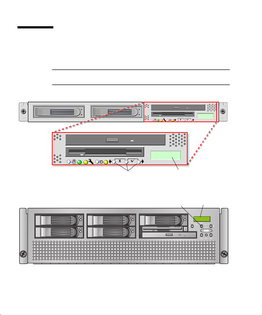
Operator Panel
You can use the operator panel to configure network settings for the SP. See
FIGURE 1-2 or FIGURE 1-3 for the operator panel location on your server.
Note – The SP defaults to Dynamic Host Configuration Protocol (DHCP)
networking if the operator panel is not interactively engaged on the first power-up.
Operator panel displayOperator panel buttons
FIGURE 1-2 Sun Fire V20z Server Operator Panel and Buttons
Operator panel buttons (3)
FIGURE 1-3 Sun Fire V40z Server Operator Panel and Buttons
6 Sun Fire V20z and Sun Fire V40z Servers, Server Management Guide • May, 2004
Operator panel display
Page 29

The operator panel displays information on the LCD display in two lines, and you
respond to prompts or initiate actions using the following buttons:
TABLE 1-2 Operator Panel Buttons
Buttons Function
Back/No
Select
Forward/Yes
Enter
Cancel
If a menu or data-entry screen displays for more than 30 seconds with no action
taken, the menu or data entry is cancelled and the display returns to the
idle/background state.
For every action that you confirm, feedback displays on the panel to indicate
success, failure, or that the action has been initiated.
The Back and Forward buttons automatically scroll, repeating the action as long as
the button is held down. After holding the button down a few seconds, auto
scrolling begins and rapidly increments or decrements the value.
Chapter 1 Introduction 7
Page 30

User Groups
Administrators can define several different user groups, or types, on the server.
Capabilities of the different user types are defined in
For example, when you log in to the system the first time using the setup account,
the first thing you must do is set up the initial manager account so that other user
accounts can be managed. (see “Creating the Initial Manager Account” on page 13
for details)
TABLE 1-3 User Types
User Type Capability
monitor Read-only access for sensor data and log displays.
admin All capabilities except user account management and SP field
upgrades
manager All capabilities except SP field upgrade
service SP field upgrades
TABLE 1-3.
8 Sun Fire V20z and Sun Fire V40z Servers, Server Management Guide • May, 2004
Page 31

Initial Setup of the Service Processor
This procedure describes the steps for the initial setup of the SP.
Part I: Assigning Network Settings to the SP
This section contains two alternate methods you can use to define SP network
settings:
■ “Assigning SP Network Settings Using DHCP” on page 9
■ “Assigning Static SP Network Settings” on page 11
Note – As an alternative, if no DHCP server or physical access is available, you can
configure the SP using IPMItool in conjunction with an IPMI kernel driver. To
configure your server for IPMI, perform the correct procedures for your operating
system in “Enabling IPMI Access on the Server” on page 14, then “Enabling IPMI
LAN Access” on page 17.
Assigning SP Network Settings Using DHCP
The following procedure describes how to set the SP network settings using DHCP
from the Operator Panel. If your network does not use DHCP, or you want to assign
a static IP address to the SP, follow the instructions in “Assigning Static SP Network
Settings” on page 11.
Note – This procedure assumes that you have cabled the server and powered it on
as described in the Sun Fire V20z and Sun Fire V40z Servers Installation Guide. At
least of the server’s SP ports must be connected to a LAN.
1. Press any operator panel button on the server front panel (see
The LCD panel displays the first menu option:
Menu:
Server Menu
FIGURE 1-4).
Chapter 1 Introduction 9
Page 32

Back Select Forward
Press both for Cancel Press both for Enter
FIGURE 1-4 Operator Panel Buttons
2. Press the Forward button until you reach the SP menu:
Menu:
SP menu
3. Press the Select button to display the SP menu options.
SP Menu:
Set SP IP info?
4. Press the Select button.
The following prompt appears with the default response:
SP use DHCP?
No
5. Press the Forward button to change to Yes, then press the Select button.
6. Press the Select button at the confirmation prompt.
SP use DHCP:
Yes?
The server attempts to contact a DHCP server for an IP address. Once a DHCP
server is contacted, the LCD panel displays the default SP settings. The SP address is
configured and the server is ready for use.
7. Continue with “Part II: Securing the Service Processor” on page 13 for instructions
on creating the initial manager account.
Note – A prompt appears that asks if you want to perform autoconfiguration. As an
alternative to configuring an SP manually, you can run autoconfiguration, which
replicates the configuration of one SP to another. Refer to “Autoconfiguring the SP
(Optional Method)” on page 24for instructions on autoconfiguration.
10 Sun Fire V20z and Sun Fire V40z Servers, Server Management Guide • May, 2004
Page 33

Assigning Static SP Network Settings
Follow these steps to set the SP network settings using a static IP address. You must
specify a subnet mask and default gateway. This example uses the following sample
settings:
IP Address: 192.168.1.2
Subnet Mask: 255.255.255.0
Default Gateway: 192.168.1.254
1. Press any operator panel button on the server front panel (see
The LCD panel displays the first menu option:
Menu:
Server Menu
2. Press the Forward operator panel button until you reach the SP menu:
Menu:
SP menu
3. Press the Select operator panel button to display the SP menu options.
SP Menu:
Set SP IP info?
4. Press the Select operator panel button. The following prompt displays with the
default response:
SP use DHCP?
No
5. Press the Select operator panel button.
The LCD displays as follows:
SP IP Address:
0.0.0.0
6. With the cursor in the first field, increase or decrease the value using the Back and
Forward operator panel buttons.
This field can hold a value between 0 and 255.
SP IP Address:
10.0.0.0
FIGURE 1-4).
7. After reaching your desired value, press the Select operator panel button to
advance the cursor to the next field.
SP IP Address:
10.
0.0.0
Chapter 1 Introduction 11
Page 34

Note – The Back and Forward operator panel buttons automatically scroll, repeating
the action as long as the button is held down.
8. Repeat Step 6 and Step 7 for each field until the desired IP address is displayed,
then use the Enter button combination to save the IP Address.
The process continues to the next network setting, the Subnet Mask. The LCD
displays as follows:
SP netmask:
255.255.255.0
9. Edit the subnet mask setting in the same manner as you did for the IP address.
When finished, use the Enter button combination to save the subnet mask.
The process continues to the next network setting, the default gateway. The LCD
displays as follows:
SP IP Gateway
10.10.30.1
10. Edit the default gateway setting in the same manner as you did for the IP address
and the subnet mask. When finished, use the Enter button combination to save the
default gateway.
The LCD displays the following confirmation prompt:
Use new IP data:
Yes?
11. Press the Select operator panel button to use the new data, or use the Cancel
button combination to disregard.
The SP address is now configured and the server is ready for use.
Note – A prompt appears that asks if you want to perform autoconfiguration. As an
alternative to configuring an SP manually, you can run autoconfiguration, which
replicates the configuration of one SP to another. Refer to “Autoconfiguring the SP
(Optional Method)” on page 24 for instructions on autoconfiguration.
12. Continue with “Part II: Securing the Service Processor” on page 13.
12 Sun Fire V20z and Sun Fire V40z Servers, Server Management Guide • May, 2004
Page 35

Part II: Securing the Service Processor
After you install the server and configure the SP, you must create the initial manager
account to secure and access the server. You can then perform initial configuration of
the server and create additional user accounts.
Creating the Initial Manager Account
A setup account is included with each server. This setup account has no password.
When you log in to the SP the first time using the setup account, you are prompted
to define the initial manager account with a password and an optional public key.
Log in to the setup account and create the initial manager account by following this
procedure:
1. Using an SSHv1 or SSHv2 client, connect to the IP address of the SP.
2. Authenticate as the user setup with no password required:
# ssh sp_ip_address -l setup
3. Follow the on-screen prompts to create the initial manager account.
After you create the initial manager account, the setup account is deleted and you
are logged out of the server. You can then log in using the new manager account,
from which you can create other user accounts.
Note – If you are prompted for a password, this indicates that the SP has already
been secured. If you do not know the management user name and password, you
can reset the SP from the operator panel.
Note – The IP address, user name, and password that you configure are referred to
in subsequent examples as the spipaddr, spuser and sppasswd.
Chapter 1 Introduction 13
Page 36

Enabling IPMI Access on the Server
This section contains two alternate procedures; one for a Linux-based server and one
for a Solaris-based x86 server. Use the procedure that corresponds to your OS:
■ “Enabling IPMI Access on a Linux-Based Server (In-Band)” on page 14
■ “Enabling IPMI Access on a Solaris-Based x86 Server (In-Band)” on page 16
Enabling IPMI Access on a Linux-Based Server (In-Band)
1. Log in to the server and authenticate as the user root.
2. Install the custom openIPMI Linux kernel driver from the Sun Fire V20z and Sun
Fire V40z Servers Documentation and Support Files CD. The drivers are located
in the CD directory /support/sysmgmt/.
Browse to the OS variant installed on your server. The options are:
■ redhat/rhel3 for Red Hat Enterprise Linux, version 3 (32-bit mode uses the
architecture type “i386”; 64-bit mode uses architecture type “x86_64”)
■ suse/sles8 for SUSE Enterprise Linux, version 8 (32-bit mode uses the architecture
type “i386”; 64-bit mode uses architecture type “x86_64”)
■ suse/suse9 for SUSE 9 Professional
3. Ensure that the kernel-source RPM is already installed on your distribution by
running the command:
# rpm -qvi kernel-source
If this utility reports that the kernel-source software package is not installed, install
the kernel-source RPM that is current for your installed Linux distribution.
■ On SUSE distributions, install the kernel-source RPM by running the command:
# yast2
■ On RedHat distributions, download the current kernel-source RPM to a
temporary directory (such as /tmp). Install the package by running the command:
# rpm -ivh /tmp/kernel-source*.rpm
4. Install the openIPMI Linux kernel driver RPM.
a. Browse to the OS variant installed on your server. The options are:
■ redhat/rhel3 for Red Hat Enterprise Linux, version 3 (32-bit mode uses the
architecture type “i386”; 64-bit mode uses architecture type “x86_64”)
■ suse/sles8 for Suse Enterprise Linux, version 8 (32-bit mode uses the
architecture type “i386”; 64-bit mode uses architecture type “x86_64”)
■ suse/suse9 for Suse 9 Professional
14 Sun Fire V20z and Sun Fire V40z Servers, Server Management Guide • May, 2004
Page 37

b. Install the openIPMI RPM file by running the command:
# rpm -ivh openipmi*.rpm
Note – The kernel driver will be compiled using the kernel-source code during
installation.
5. Install IPMItool.
IPMItool is the command-line-interface (CLI) server-management client.
■ If the installed Linux distribution uses the 32-bit “i386” architecture, run the
following command:
# rpm -ivh ipmitool*.i386.rpm
■ If the installed Linux distribution uses the 64-bit “x86_64” architecture, run the
following command:
# rpm -ivh ipmitool*.x86_64.rpm
6. Test the IPMI kernel device driver and client application by running the
following command:
# ipmitool -I open chassis status
Successful output should look similar to the following:
"
System Power: on
Power Overload: false
Power Interlock: inactive
Main Power Fault: false
Power Control Fault: false
Power Restore Policy: unknown
Last Power Event:
Chassis Intrusion: inactive
Front-Panel Lockout: inactive
Drive Fault: false
Cooling/Fan Fault: false
"
Note – On a subsequent reboot, the IPMI kernel driver may have to be loaded with
the following command:
# modprobe ipmi_kcs_drv
Note – If you upgrade your Linux kernel, refer to “Upgrading the Linux Kernel” on
page 19.
Chapter 1 Introduction 15
Page 38

Enabling IPMI Access on a Solaris-Based x86 Server (In-Band)
1. Log in to the server and authenticate as the user root.
2. Run the following command to install the LIPMI Solaris x86 kernel driver and the
IPMItool management control application.
These files are located on the Documentation and Support Files CD in the
/support/sysmgmt/solaris9 directory.
# pkgadd -d ./
Confirm installation of all packages when prompted.
3. Reboot the server.
16 Sun Fire V20z and Sun Fire V40z Servers, Server Management Guide • May, 2004
Page 39

Enabling IPMI LAN Access
This section contains three alternate procedures; two in-band procedures, and one
out-of-band procedure. Use the procedure that corresponds to your OS:
■ “Enabling IPMI LAN Access on a Linux-Based Server (In-Band)” on page 17
■ “Enabling IPMI LAN Access on a Solaris-Based x86 Server (In-Band)” on page 18
■ “Alternate Method for Enabling IPMI LAN Access (Out-of-Band)” on page 18
Enabling IPMI LAN Access on a Linux-Based Server
(In-Band)
1. If the server is powered off, boot the local OS.
2. Log in to the server and authenticate as the user root.
3. Load the OpenIPMI kernel device driver (as installed in Part III, Step 3).
# modprobe ipmi_kcs_drv
4. Using IPMItool, configure the network setting for the SP.
Note – For more information on the syntax for IPMItool commands, refer to
“Syntax” on page 30.
# ipmitool -I open lan set 6 ipaddr ipaddr
# ipmitool -I open lan set 6 netmask netmask
# ipmitool -I open lan set 6 defgw ipaddr gwipaddr
# ipmitool -I open lan set 6 password ipmipasswd
Chapter 1 Introduction 17
Page 40

Enabling IPMI LAN Access on a Solaris-Based x86 Server
(In-Band)
1. If the server is powered off, boot the local OS.
2. Log in to the server and authenticate as the user root.
3. Using IPMItool, configure the network setting for the SP by using the following
commands.
Note – For more information on the syntax for IPMItool commands, refer to
“Syntax” on page 30.
# ipmitool -I lipmi lan set 6 ipaddr ipaddr
# ipmitool -I lipmi lan set 6 netmask netmask
# ipmitool -I lipmi lan set 6 defgw ipaddr gwipaddr
# ipmitool -I lipmi lan set 6 password ipmipasswd
Alternate Method for Enabling IPMI LAN Access (Out-ofBand)
1. Using an SSHv1 client or SSHv2 client, log in to the IP address of the SP.
2. Authenticate as the newly created management user (see “Part II: Securing the
Service Processor” on page 13”).
# ssh spipaddr -l spuser
3. Enable IPMI LAN access and assign a password when prompted.
# ipmi enable channel lan
# exit
Note – This password will be referred to as ipmipasswd in subsequent examples.
4. Using IPMItool, test the IPMI LAN access.
# ipmitool -I lan -H spipaddr -P ipmipasswd chassis status
18 Sun Fire V20z and Sun Fire V40z Servers, Server Management Guide • May, 2004
Page 41

Upgrading the Linux Kernel
Upgrading the installed Linux kernel to a newer version requires you to recompile
the upgraded IPMI kernel device driver.
1. Install the kernel-source RPM that matches the version of the upgraded kernel
binary RPM package.
2. Log in to the server and authenticate as the user root.
3. Change to the following directory:
# cd /usr/src/kernel-modules/openipmi
4. Recompile the module by running the following commands:
# make clean
# make
# make install
5. Re-test the IPMI kernel device driver and client application by running the
following command:
# ipmitool -I open chassis status
Successful output should look similar to the following:
"
System Power: on
Power Overload: false
Power Interlock: inactive
Main Power Fault: false
Power Control Fault: false
Power Restore Policy: unknown
Last Power Event:
Chassis Intrusion: inactive
Front-Panel Lockout: inactive
Drive Fault: false
Cooling/Fan Fault: false
"
Note – On a subsequent reboot, the IPMI kernel driver may have to be loaded with
the following command:
# modprobe ipmi_kcs_drv
Chapter 1 Introduction 19
Page 42

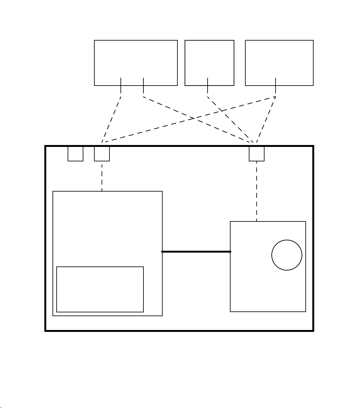
Daisy-Chaining the Servers
You can interconnect multiple servers in a daisy chain configuration by using the SP
connectors to form a management LAN as shown in
shows how the servers are connected to external LANs using the platform gigabit
connectors.
FIGURE 1-5. This figure also
= SP 10/100
connectors for
management LAN
Mngmt
console
Cross-overCross-over
Management LAN
NFS/CIFS
server
FIGURE 1-5 Daisy Chain Architecture
SP
MGMT
SP
MGMT
SP
MGMT
= GB 100/1000
connectors for
external LANs
Server
Server
External LANs
Server
Internet
To interconnect the servers, you must use an RJ-45 cross-over cable. Cables can be
connected to either the top or bottom SP port. To configure servers in a daisy chain,
connect the first and last server in the chain to different switches.
Managed spanning-tree capable switches are required to redundantly connect both
the top and bottom of the chain. If the switch is not capable of spanning-tree
discovery, then only connect either to the top or the bottom of the chain, but not
both.
20 Sun Fire V20z and Sun Fire V40z Servers, Server Management Guide • May, 2004
Page 43

Site Integration
When deploying your server, ensure that you determine the best integration strategy
for your environment.
These servers include network connections for the service processor (SP) that are
separate from network connections for the platform. This allows you to configure
the server so that the SP is connected to an isolated, management network and is not
accessible from the production network.
Updating the SP Software
Note – For complete information about the menu options available through the
operator panel, refer to the Sun Fire V20z and Sun Fire V40z Servers User Guide.
If you attempt to update the SP software using the operator panel when the
IP address for the SP has not been set, the update fails. Ensure that the IP address
has been set prior to attempting an update. For more information, refer to the Sun
Fire V20z and Sun Fire V40z Servers Installation Guide.
Refer to “Operator Panel” on page 6 for general orientation and usage of the
operator panel.
Note – Prior to executing this procedure, you must start the Java™ Update Server.
Refer to “Updating the Service Processor Base Component” on page 23 for details
about starting the Java Update Server.
To update the SP software:
1. When the LCD displays the Service Processor information (as shown in the
following example), press any button.
123.45.67.89
OS running
The LCD displays the first menu option:
Menu:
Server Menu
Chapter 1 Introduction 21
Page 44

2. Press the Forward button until you reach the SP menu.
Menu:
SP menu
3. Press Select or Enter to display the SP menu’s options.
SP Menu:
Set SP IP info?
4. Press the Forward button until you reach the Update SP Flash menu option.
SP Menu:
Update SP Flash?
5. Press Select or Enter.
6. A string of 0s displays with the cursor at the left digit. Use the Forward and Back
buttons to increment or decrement a digit.
Note – You are prompted for an IP address. If you attempt to update the SP
software using the operator panel when the IP address for the SP has not been set,
the update fails.
Note – If you need to supply a port address, it can be any number between 0 and
65535. The leading 0s are removed.
See Step 3 in “Updating the Service Processor Base Component” on page 23 for more
information.
7. Press Select to move to the next digit.
8. Press Select when finished to return to the left-most column.
9. Press the button combination for Enter.
22 Sun Fire V20z and Sun Fire V40z Servers, Server Management Guide • May, 2004
Page 45

Updating the Service Processor Base Component
To update the SP base component:
1. Start the spupdate server on a machine with a Java Runtime Environment (JRE) by
running the following command:
# java -jar spupdate.jar -f filename [ -p port ]
The spupdate.jar file is located in the spupdate folder of the Network Share
Volume (NSV).
In this command, filename is an SP .image file located in
sw_images/sp/spbase/version. This sw_images directory contains an SP base
.image file for each version available.
By default, the server uses port number 52708. If this port number is already in use,
specify another port using the optional -p flag.
The update server does not start if the file is not found in the specified path.
Otherwise, the server is ready to receive update requests from any SP. The update
server can simultaneously accept multiple update requests from different SPs.
2. Log in to the SP by running the following command:
# ssh spipaddr -l spuser
3. Run the sp command to start the update process on the SP:
# sp update flash all {-i | --ipaddress} IPADDRESS [{-p | --port} PORT]
Note – This command includes the optional -p flag to denote that the server is
running on a port other than the default port. This command pings the update
server to see if the update server is up and running. If successful, your connection is
closed when the SP reboots and the update process begins.
Refer to Appendix B for more information about the sp commands.
4. Monitor progress of the update process on the server.
Messages display as the installation process progresses. When complete, the SP
reboots with the new version installed.
Chapter 1 Introduction 23
Page 46

Autoconfiguring the SP (Optional Method)
Autoconfiguration replicates the majority of configuration files from an SP that has
already been configured to another SP, so that the two servers have identical
configurations, except for the host name and IP address.
For example, after you configure a single SP (set up users, hosts, certificates, mounts
and so on), you then run autoconfiguration on each additional SP so that the settings
are identical. In addition, if you modify the configuration of one SP, you can update
all of them by re-running autoconfiguration on each one. (For this reason, set the
IP address of the autoconfigure server to x.x.x.1.)
Note – Autoconfiguration does not merge configurations, it overwrites the existing
configuration.
Note – Autoconfiguration does not work across diffrent server platforms. That is,
you cannot configure a Sun Fire V40z service processor using settings on a Sun Fire
V20z service processor.
To perform autoconfiguration of an SP, follow these steps:
You can start autoconfiguration either when you are prompted at the completion of
setting the IP address of the SP, or by selecting Autoconfigure from the SP menu
option on the operator panel at any time.
1. On the operator panel, press the Forward or Back buttons until the following
prompt shows Yes.
SP Auto Setup?
No
For instructions on setting an IP address, refer to the Sun Fire V20z and Sun Fire V40z
Server Installation Guide.
2. Press the Select button.
The SP attempts to locate an IP address.
■ If the SP successfully locates an IP address, the following prompt appears,
displaying an IP address for this SP:
Setup Server IP:
x.x.x.1
Where x.x.x is the first three octets of the SP IP address. For example, if the
address is 10.10.30.19, the address that displays in the prompt appears as
10.10.30.1.
In this case, press the Select operator panel button to start autoconfiguration.
24 Sun Fire V20z and Sun Fire V40z Servers, Server Management Guide • May, 2004
Page 47

■ If the SP does not locate an IP address, the following message appears:
Unable to get
SP IP address
In this case, you must manually enter an IP address before you press the Select
operator panel button to start autoconfiguration.
3. Wait until the autoconfiguration is complete, at which point the SP automatically
reboots.
The following message displays when autoconfiguration is running.
SP AutoConfigure
in progress
Note – If the autoconfiguration is unsuccessful, a failure message displays. Press
any button to clear it.
Determining SP and Platform Network MAC Addresses
Use the following commands if you need to determine the MAC address of your
server’s SP or platform:
# ssh spipaddress -l spusername sp get mac
# ssh spipaddress -l spusername platform get mac
Chapter 1 Introduction 25
Page 48

26 Sun Fire V20z and Sun Fire V40z Servers, Server Management Guide • May, 2004
Page 49

CHAPTER
2
IPMI Server Management
Server manufacturers today have to re-invent how each new server manages itself.
The hardware and software design for one server does not necessarily work with
another. Every server supplier provides basic monitoring and data collection
functions but no two do it exactly the same. These proprietary implementations for
manageability only complicate the problem.
The standardization of server-based management, called Intelligent Platform
Management Interface (IPMI), provides a solution. IPMI allows you to interconnect
the CPU and devices being managed. It allows for:
■ Easy replication of the monitoring functions from server to server
■ Support for a reasonably large number of monitoring devices
■ Common driver-level access to management instrumentation
■ More cost-effective implementations
■ Increased scalability of the server management functions
IPMI is an industry-standard, hardware-manageability interface specification that
provides an architecture defining how unique devices can all communicate with the
CPU in a standard way. It facilitates platform-side server management and remote
server-management frameworks, by providing a standard set of interfaces for
monitoring and managing servers.
With IPMI, the software becomes less dependent on hardware because the
management intelligence resides in the IPMI firmware layer, thereby creating a more
intelligently managed server. The IPMI solution increases server scalability by
distributing the management intelligence closer to the devices that are being
managed.
27
Page 50

Baseboard Management Controller
In order to perform autonomous platform-management functions, the processor
runs embedded software or firmware. Together, the processor and its controlling
firmware are referred to as the Baseboard Management Controller (BMC), which is
the core of the IPMI structure. Tightly integrating an IPMI BMC and management
software with platform firmware facilitates a total management solution.
The BMC is a service processor integrated into the motherboard design, providing a
management solution independent of the main processor. The monitored server can
communicate with the BMC through one of three defined interfaces, which are based
on a set of registers shared between the platform and the BMC.
Note – In these servers, the SP has software that emulates a BMC.
The BMC is responsible for:
■ Managing the interface between server management software and platform
management hardware
■ Interfacing to the system sensors, such as fan speed and voltage monitors
■ Providing access to the system event log
■ Providing autonomous monitoring, event logging, and recovery control
■ Acting as a gateway between the management software and the IPMB/ICMB
■ Monitoring the system watchdog timer
■ Facilitating the remote-management tasks, even when the main server hardware
is in an inoperable state
The BMC provides the intelligence behind IPMI. In these servers, the SP serves as
the BMC, providing access to sensor data and events through the standard IPMI
interfaces.
Manageability
IPMI defines a mechanism for server monitoring and recovery implemented directly
in hardware and firmware. IPMI functions are available independent of the main
processors, BIOS, and operating system.
IPMI monitoring, logging, and access functions add a built-in level of manageability
to the platform hardware. IPMI can be used in conjunction with server-management
software running under the OS, which provides an enhanced level of manageability.
IPMI provides the foundation for smarter management of servers by providing a
methodology for maintaining and improving the reliability, availability and
serviceability of expensive server hardware.
28 Sun Fire V20z and Sun Fire V40z Servers, Server Management Guide • May, 2004
Page 51

IPMI Compliance and LAN Channel Access
The server supports IPMI through the SP software version 2.0 and later. These
servers meet compliance standards for IPMI version 1.5.
The IPMI implementation on these servers also support LAN channel access. (Refer
to the IPMI specification version 1.5 for details.) The LAN channel access is disabled
by default. To enable it, use the ipmi enable channel command and specify the
ID of the channel to enable for the LAN Interface, as follows.
Note – This ID is case-sensitive and must be lowercase.
# ssh spipaddr -l spuser ipmi enable channel {sms | lan}
For more information about enabling or disabling the IPMI channel, refer to
Appendix B.
Usernames and Passwords
Operator and administrator-level access over the LAN channel requires a valid
user ID and password. These servers come preconfigured with an administratorlevel user with a null user ID. However, you can re-add the anonymous user at a
later time if you wish. You can configure both the user ID and password to be null.
Note – For security reasons, the LAN channel access is disabled by default.
Note – IPMI user identities are in no way associated with user accounts defined for
server-management capabilities. Refer to “Initial Setup of the Service Processor” on
page 9 for more information about these server-management user accounts.
Chapter 2 IPMI Server Management 29
Page 52

Lights Out Management (LOM)
On these servers, Lights Out Management is performed through IPMItool, a utility
for controlling IPMI-enabled devices.
Description
IPMItool is a simple command-line interface (CLI) to servers that support the
Intelligent Platform Management Interface (IPMI) v1.5 specification. It provides the
ability to:
■ Read the Sensor Data Record (SDR) and print sensor values
■ Display the contents of the System Event Log (SEL)
■ Print information about Field Replaceable Units (FRUs)
■ Read and set LAN configuration parameters
■ Perform chassis power control
Originally written to take advantage of IPMI-over-LAN interfaces, IPMItool is also
capable of using a system interface, as provided by a kernel device driver such as
OpenIPMI.
Further Information
■ For up-to-date information about IPMItool, visit:
http://ipmitool.sourceforge.net/
■ For more information about the IPMI specification, visit:
http://www.intel.com/design/servers/ipmi/spec.htm
■ For more information about the OpenIPMI project (MontaVista IPMI kernel
driver), visit:
http://openipmi.sourceforge.net/
Syntax
The syntax used by IPMItool is as follows:
ipmitool [-ghcvV] -I lan -H address [-P password] expression
ipmitool [-ghcvV] -I open expression
30 Sun Fire V20z and Sun Fire V40z Servers, Server Management Guide • May, 2004
Page 53

Options
TABLE 2-1 lists the options available for IPMItool.
TABLE 2-1 Options for IPMItool
Option Description
-h Provides help on basic usage from the command line.
-c Makes the output suitable for parsing, where possible, by separating
fields with commas instead of spaces.
-g Attempts to make IPMI-over-LAN communications more robust.
-V Displays the version information.
-v Increases the amount of text output. This option may be specified
more than once to increase the level of debug output. If given three
times, you receive hexdumps of all incoming and outgoing packets.
-I interface Selects the IPMI interface to use. The possible interfaces are LAN or
open interface.
-H address Displays the address of the remote server; it can be an IP address or
host name. This option is required for the LAN interface connection.
-P password Displays the password for the remote server; the password is
limited to a maximum of 16 characters. The password is optional for
the LAN interface; if a password is not provided, the session is not
authenticated.
Chapter 2 IPMI Server Management 31
Page 54

Expressions
TABLE 2-2 lists the expressions and parameters available for IPMItool.
Note – For each of these expressions, the beginning command is always ipmitool,
followed by the expression and parameter(s).
Note – The sol command is not supported in these servers, but you can enable a
Serial-over-LAN feature. See “Serial Over LAN” on page 70.
TABLE 2-2 Expressions and Parameters for IPMItool (1 of 4)
Expression Parameter Sub-parameter Description and examples
help Can be used to get command-line help on IPMItool
commands. It may also be placed at the end of commands
to get help on the use of options.
EXAMPLES:
ipmitool -I open help
Commands: chassis, fru, lan, sdr, sel
ipmitool -I open chassis help
Chassis Commands: status, power, identify,
policy, restart_cause
ipmitool -I open chassis power help
Chassis Power Commands: status, on, off, cycle,
reset, diag, soft
raw netfn cmd data Allows you to execute raw IPMI commands (for example,
to query the POH counter with a raw command).
EXAMPLE:
ipmitool -I open raw 0x0 0x1
RAW REQ (netfn=0x0 cmd=0x1 data_len=0)
RAW RSP (3 bytes)
60 00 00
32 Sun Fire V20z and Sun Fire V40z Servers, Server Management Guide • May, 2004
Page 55

TABLE 2-2 Expressions and Parameters for IPMItool (2 of 4)
Expression Parameter Sub-parameter Description and examples
chaninfo channel Displays information about the selected channel. If no
channel is specified, the command displays information
about the channel currently being used.
EXAMPLES:
ipmitool -I open chaninfo
Channel 0xf info:
Channel Medium Type: System Interface
Channel Protocol Type: KCS
Session Support: session-less
Active Session Count: 0
Protocol Vendor ID: 7154
ipmitool -I open chaninfo 7
Channel 0x7 info:
Channel Medium Type: 802.3 LAN
Channel Protocol Type: IPMB-1.0
Session Support: multi-session
Active Session Count: 1
Protocol Vendor ID: 7154
Alerting: enabled
Per-message Auth: enabled
User Level Auth: enabled
Access Mode: always available
userinfo channel
Note:
Displays information about configured user information
on a specific LAN channel.
Channels 6
and 7 are not
supported on
Sun Fire V20z
servers.
EXAMPLE:
ipmitool -I open userinfo 6
Maximum User IDs : 4
Enabled User IDs : 1
Fixed Name User IDs : 1
Access Available : call-in / callback
Link Authentication : disabled
IPMI Messaging : enabled
chassis status Returns information about the high-level status of the
server chassis and main power subsystem.
identify interval Controls the front panel identification light. The default
value is 15 seconds. Enter “0” to turn it off.
restart_cause Queries the chassis for the cause of the last server restart.
Chapter 2 IPMI Server Management 33
Page 56

TABLE 2-2 Expressions and Parameters for IPMItool (3 of 4)
Expression Parameter Sub-parameter Description and examples
power Performs a chassis control command to view and change
the power state.
status Shows the current status of the chassis power.
on Powers on the chassis.
off Powers off chassis into the soft off state (S4/S5 state).
NOTE: This command does not initiate a clean shutdown
of the operating system prior to powering off the server.
cycle Provides a power-off interval of at least 1 second.
No action should occur if chassis power is in S4/S5 state,
but it is recommended to check the power state first and
then only issue a power-cycle command if the server
power is on or in a lower sleep state than S4/S5.
reset Performs a hard reset.
lan print channel Prints the current configuration for the given channel.
set channel
Sets the given parameter on the given channel.
parameter
ipaddr x.x.x.x Sets the IP address for this channel.
netmask x.x.x.x Sets the netmask for this channel.
macaddr
Sets the MAC adddress for this channel.
xx:xx:xx:xx:xx:xx
defgw ipaddr
Sets the default gateway IP address.
x.x.x.x
defgw macaddr
Sets the default gateway MAC address.
xx:xx:xx:xx:xx:xx
bakgw ipaddr
Sets the backup gateway IP address.
x.x.x.x
bakgw macaddr
Sets the backup gateway MAC address.
xx:xx:xx:xx:xx:xx
password pass Sets the null user password.
user Enables the user-access mode.
access [on|off] Sets the LAN-channel-access mode.
ipsrc source Sets the IP address source. As a source, you can indicate:
none = unspecified
static = manually configured static IP address
dhcp = address obtained by BMC running DHCP
bios = address loaded by BIOS or system software
34 Sun Fire V20z and Sun Fire V40z Servers, Server Management Guide • May, 2004
Page 57

TABLE 2-2 Expressions and Parameters for IPMItool (4 of 4)
Expression Parameter Sub-parameter Description and examples
arp respond
Sets the BMC-generated ARP responses.
[on|off]
arp generate
Sets the BMC-generated gratuitous ARPs.
[on|off]
arp interval
Sets the interval for the BMC-generated gratuitous ARPs.
[seconds] s
auth level,...
type,...
This command sets the valid authtypes for a given auth
level.
Levels can be: callback, user, operator, admin
Types can be: none, md2, md5
fru print Reads all inventory data for the Customer Replaceable
Units (CRUs) and extracts such information as serial
number, part number, asset tags and short strings
describing the chassis, board or product.
sdr list Reads the Sensor Data Record (SDR) and extracts sensor
information, then queries each sensor and prints its name,
reading and status.
sel info Queries the BMC for information about the system event
log (SEL) and its contents.
clear Clears the contents of the SEL.
The clear command cannot be undone.
list Lists the contents of the SEL.
Chapter 2 IPMI Server Management 35
Page 58

IPMI Linux Kernel Device Driver
The IPMItool application utilizes a modified MontaVista OpenIPMI kernel device
driver found on the Sun Fire V20z and Sun Fire V40z Servers Documentation and
Support Files CD. The driver has been modified to use an alternate base hardware
address and modified device IO registration.
This driver must be compiled and installed from the Documentation and Support
Files CD.
The following kernel modules must be loaded in order for IPMItool to work:
1. ipmi_msghandler
The message handler for incoming and outgoing messages for the IPMI interfaces.
2. ipmi_kcs_drv
An IPMI Keyboard Controller Style (KCS) interface driver for the message
handler.
3. ipmi_devintf
Linux-character-device interface for the message handler.
To force IPMItool to use the device interface, you can specify it on the command
line:
# ipmitool -I open [option...]
Installing and Compiling the Driver
To install and compile this kernel device driver, see “Initial Setup of the Service
Processor” on page 9.
LAN Interface for the BMC
Note – In these servers, the SP has software that emulates a BMC.
The IPMItool LAN interface communicates with the BMC over an Ethernet LAN
connection using User Datagram Protocol (UDP) under IPv4. UDP datagrams are
formatted to contain IPMI request/response messages with IPMI session headers
and Remote Management Control Protocol (RMCP) headers.
36 Sun Fire V20z and Sun Fire V40z Servers, Server Management Guide • May, 2004
Page 59

Remote Management Control Protocol is a request-response protocol delivered using
UDP datagrams to port 623. IPMI-over-LAN uses version 1 of the RMCP to support
management both before installing the OS on the server, or if the server will not
have an OS installed.
The LAN interface is an authenticated, multi-session connection; messages delivered
to the BMC can (and should) be authenticated with a challenge/response protocol
with either a straight password/key or an MD5 message-digest algorithm. IPMItool
attempts to connect with administrator privilege level as this is required to perform
chassis power functions.
With the -I option, you can direct IPMItool to use the LAN interface:
# ipmitool -I lan [option...] address password
To use the LAN interface with IPMItool, you must provide a host name on the
command line.
The password field is optional; if you do not provide a password on the command
line, IPMItool attempts to connect without authentication. If you specify a password,
it uses MD5 authentication, if supported by the BMC; otherwise, it will use straight
password/key.
Files
The file /dev/ipmi0 is a character-device file used by the OpenIPMI kernel driver.
Examples
If you want to remotely control the power of an IPMI-over-LAN-enabled server, you
can use the following commands:
#
ipmitool -I lan -H spipaddr -P sppasswd chassis power on
The result returned is:
Chassis Power Control: Up/On
# ipmitool -I lan -H spipaddr -P sppasswd chassis power status
The result returned is:
Chassis Power is on
Chapter 2 IPMI Server Management 37
Page 60

Viewing the IPMI System Event Log
To view the System Event Log (SEL), use IPMItool.
The out-of-band command is:
# ipmitool -I lan -H spipaddr -P ipmipasswd sel list
The in-band command (using OpenIPMI on a Linux-based server or LIPMI on a
Solaris-based server) is:
# ipmitool -I open sel list
Note – To receive more verbose logging messages, you can run the following
command:
# ssh -l spuser spipaddr sp get events
Clearing the IPMI System Event Log
You can use commands to clear the contents of the IPMI SEL.
Use one of the following commands, depending on your OS:
■ For Linux: ipmitool -I open sel clear
■ For Solaris: ipmitool -I lipmi sel clear
38 Sun Fire V20z and Sun Fire V40z Servers, Server Management Guide • May, 2004
Page 61

IPMI Troubleshooting
TABLE 2-3 describes some potential issues with IPMI and provides solutions.
TABLE 2-3 IPMI Troubleshooting
Issue Solution
You cannot connect to the
management controller using
IPMItool over LAN.
Verify the network connection to the management
controller and its IP address and verify the channel is
enabled using the ipmi get channels command.
You cannot authenticate to the
management controller using
IPMItool over LAN.
You have forgotten the password
for IPMI access over LAN.
IPMItool fails when using the
“open” interface.
Ensure that you are using the password assigned
when you enabled IPMI LAN access from the
management-controller shell prompt.
1. You can reset the IPMI setting, reset the SDRR and
purge the SEL from the management-controller
shell by running the command:
# ssh spipaddr -l spuser ipmi reset -a
2. Now re-enable IPMI on LAN with the following
commands:
# ssh spipaddr -l spuser
# ipmi enable channel lan
# exit
Ensure that the Linux kernel module ipmi_kcs_drv
is loaded by running the lsmod command.
Chapter 2 IPMI Server Management 39
Page 62

40 Sun Fire V20z and Sun Fire V40z Servers, Server Management Guide • May, 2004
Page 63

CHAPTER
3
SNMP Server Management
You can manage your server using the Simple Network Management Protocol
(SNMP).
Simple Network Management Protocol
Simple Network Management Protocol (SNMP) is a network-management protocol
used almost exclusively in TCP/IP networks. SNMP provides a means to monitor
and control network devices, and to manage configurations, statistics collection,
performance and security on a network.
SNMP-based management allows for third-party solutions to be used. This includes
products such as HP OpenView and CA Unicenter.
The base component of an SNMP solution is the Management Information Base
(MIB). The MIB is included on the Sun Fire V20z and Sun Fire V40z Servers Network
Share Volume CD.
This configuration is beneficial when, for example, you have a cluster of machines
serving Web content and the platform is connected to the Internet, but the SP is
protected and only accessible on an internal network.
41
Page 64

SNMP Integration
SNMP is an open network-management technology that enables the management of
networks and entities connected to the network. Within the SNMP architecture is a
collection of network-management stations and managed nodes.
Network-management stations execute management applications, which monitor
and control managed nodes. Managed nodes are devices such as hosts, gateways
and so on, which have management agents responsible for performing the
management functions requested by the management stations.
SNMP is used to communicate management information between the management
stations and the agents. In other words, SNMP is the protocol by which the agent
and the management station communicate.
The monitoring of state through SNMP at any significant level of detail is
accomplished primarily by polling for appropriate information on the part of the
management station. Managed nodes may also provide unsolicited status
information to management stations in the form of traps, which is likely to guide the
polling at the management station.
Communication of information between management entities in a network is
accomplished through the exchange of SNMP-protocol messages, both in the form of
queries (get/set) by the management station and in the form of unsolicited messages
(traps) indicated by the agent.
Your server includes SNMP agents that allow for health and status monitoring. The
SNMP agent runs on the SP and therefore all SNMP-based management of the
server should occur through the SP. The SNMP agent on these servers provides the
following capabilities:
■ Event management
■ Inventory management
■ Sensor and system state monitoring
■ SP configuration monitoring
SNMP Management Information Base (MIB)
The Management Information Base (MIB) is a text file that describes SNMP data as
managed objects. These servers provide SNMP MIBs so that you can manage and
monitor your server using any SNMP-capable network management system, such as
HP OpenView Network Node Manager (NNM), Tivoli, CA Unicenter, IBM Director
and so on. The MIB data describes the information being managed, reflects current
and recent server status, and provides server statistics.
42 Sun Fire V20z and Sun Fire V40z Servers, Server Management Guide • May, 2004
Page 65

Sun Fire V20z and Sun Fire V40z Servers MIB Tree
FIGURE 3-1 illustrates the MIB tree:
FIGURE 3-1 MIB Tree
Integrating MIBs with Third-Party Consoles
You use the server’s MIBs to integrate the management and monitoring of the server
into SNMP management consoles. The MIB branch is a private enterprise MIB,
located at object identifier (OID) 1.3.6.1.2.1.9237. The standard SNMP port 161 is
used by the SNMP agent on the SP.
Chapter 3 SNMP Server Management 43
Page 66

Configuring SNMP on Your Server
Note – There are several services that are supplied by the SNMP agent on the
server. Depending on your business needs and the configuration of your current
office network and management environment, you might want to take advantage of
these services.
There are certain prerequisites and setup required on both the SP and the platform
in order to enable and utilize each of these services:
■ SNMP agent on the SP
■ Proxy forwarder application/ProxyAgent [RFC 2271]
■ Agent X [RFC 2741]
The following diagram illustrates the SNMP architecture and communication paths
between the SP and the platform.
FIGURE 3-2 SNMP Architecture and Communications
44 Sun Fire V20z and Sun Fire V40z Servers, Server Management Guide • May, 2004
Page 67

SNMP Agent on the Service Processor
The SNMP agent running on the SP facilitates the management and monitoring of
the server. The SNMP agent can be used to query various types of SP information.
Refer to
of the MIBs.
There is no configuration required to use this functionality other than integrating the
server MIBs with your desired management station.
Refer to the procedure for using the SNMP agent on the SP, as explained in
“Integrating MIBs with Third-Party Consoles” on page 43.
FIGURE 3-1 for a list of the MIBs; refer to TABLE 3-3 for a detailed description
Note – The SNMP agent on these servers supports SNMP v1/v2c. For security
reasons, there are no settable attributes in this agent.
Proxy Agent
The SP acts as an SNMP proxy agent intermediary for the platform. Queries made
from a management station to the SNMP agent on the SP are intercepted by the
proxy agent on the SP and forwarded to the platform; the SP proxy agent contacts
the platform to retrieve the requested information. The proxy agent then receives the
data from the platform and sends the request back to the management station. The
management station never knows that the request was proxied. The SP and the
platform communicate over an internal private network.
To enable this facility, you must first run an SNMP agent on your platform operating
system (see your operating system vendor to obtain this agent). This enables
platform-level management transparently through the SP. Querying MIBs other than
the server MIB (for example, the Host Resource MIB) and the MIBII System MIB on
the SP obtains information from the platform by proxying the request to the
platform SNMP agent.
Ensure that the SP can identify the read-only and read-write community names that
are configured for your platform SNMP agent. Refer to “Setting the Community
Name” on page 46.
Chapter 3 SNMP Server Management 45
Page 68

Setting the Community Name
The SNMP agent on the SP acts as a proxy for the SNMP agent running on the
platform. (Refer to “Configuring SNMP on Your Server” on page 44.) To properly
proxy, you must use the community string. The community string needed to do so is
the value defined when you configured the platform for SNMP.
If you find that your SNMP queries are not being proxied to the platform SNMP
agents, validate that the community string on the SP matches that on the platform.
The SP proxy community string can be changed to match the platform community
string using the following command:
# sp set snmp proxy community
There are no restrictions on the length of the community strings; common names are
private and public. The default name is public.
For more information, refer to “SP Set SNMP Proxy Community Subcommand” on
page 109.
Agent X
A sub-agent using SNMP Agent X protocol on the platform can connect to the SNMP
agent on the SP (through a special port) and forward query responses or unsolicited
traps through the SP. This allows server-management traffic to be kept secure from
the production network connected to the platform, if required.
To properly enable this facility, you must identify the IP address and port number
pair associated with the SP (as seen from the platform). The Agent X port is fixed
at 705 (TCP). However, the private-network IP address is configurable and, by
default, this address is 169.254.101.2.
Refer to your application documentation for instructions on configuring the
sub-agents.
Note – You can use the subcommand, sp get jnet on the SP to retrieve the JNET
IP address of the SP.
46 Sun Fire V20z and Sun Fire V40z Servers, Server Management Guide • May, 2004
Page 69

Using a Third-Party MIB Browser
The following example demonstrates integrating the server MIBs into an SNMP
node manager.
1. From the Manager Preferences menu, choose Load/Unload MIBS: SNMP.
2. Locate and select the SP-MasterAgent-MIB.mib.
3. Click Load.
4. Specify the directory in which the server MIBs are placed and click Open.
5. Repeat steps 2 through 4 to load other MIBS (for example, SP-SST-MIB.mib,
SP-INVENTORY-MIB.mib, SP-EVENT-MIB.mib, SP-PLATFORM-MIB.mib,
SP-GROUP-MIB.mib and so on).
6. Exit the Manager Preferences menu.
7. Open an SNMP MIB browswer.
The SNMP standard tree displays in the MIB Browser.
8. Locate the Newisys branch located under private.enterprises.
Refer to
FIGURE 3-1 for a sample view of the MIB tree.
Setting Logging Options
You can also easily integrate SP-generated traps and set logging options. The
following example demonstrates the necessary steps when using
HP OpenView NNM:
1. Load the SP-EVENT-MIB.mib according to the previous procedure.
2. Choose Options>EventConfiguration
3. Select the spEvent module from the Enterprises list.
4. Double-click an event from the Events for Enterprise spEvent list.
5. Select the Event Message tab.
6. Select the Log and display in category radio dialog and choose a category from the
corresponding dropdown list, or create your own event category.
7. Select the severity of the event from the Severity dropdown list.
8. Enter a message or $* to display all information in the Event Log Message field.
9. Click OK.
Chapter 3 SNMP Server Management 47
Page 70

SNMP Traps
SNMP traps are network-management notifications of an event occurring at a
managed network node. These events can identify problems in the network,
machines up or down, and so on. These servers use traps to signal conditions related
to the server’s health, including critical conditions related to physical components,
the return to a normal state for these components, and other situations related to the
state of the software running on the SP (for example, network settings being
reconfigured).
Traps are defined in the MIB files and are generated, received, and processed by an
SNMP management station. SNMP trap data is uniquely identified by the MIB. Each
SNMP trap contains information identifying the server's name, IP address, and other
relevant data about the event.
Within the server event MIB, each trap has the following variables and event
bindings; see
TABLE 3-1 Server Event Traps
Event Description
EventID Uniquely identifies the event on the SP from
EventSource Denotes the source module that generated the
EventComponent Denotes the component ID about which the
EventDescription The event message received from its source.
EventTimeStampInitial The time at which this event ID was initially
EventTimeStampLast The most recent time at which this event ID was
TABLE 3-1.
where it came.
event.
event refers.
generated.
generated.
48 Sun Fire V20z and Sun Fire V40z Servers, Server Management Guide • May, 2004
Page 71

Configuring SNMP Trap Destinations
Although SNMP traps are generated for events that occur on the SP, you must
configure where these traps are to be sent. There is no default destination for traps.
You can use the server-management subcommands (see
TABLE 3-2) on the SP to
configure SNMP destinations.
For more information on these subcommands, refer to Appendix B.
TABLE 3-2 Subcommands for Configuring SNMP Destinations
Subcommand Description
sp get snmp-destinations Displays all the available SNMP destination
IP addresses and host names to which the SP will send.
sp add snmp-destination Adds a new SNMP destination one IP address or host
name at a time.
sp delete snmpdestination
Removes an existing SNMP destination one IP address
or host name at a time.
Configuring SNMP Destinations
Administration- and manager-level users can define SNMP destinations to which
SNMP events (alerts) will be sent using this option. All users can view the current
destinations (using read-only access).
The number of destinations you can create is limited due to memory constraints.
Chapter 3 SNMP Server Management 49
Page 72

Server MIB Details
SNMP uses object identifiers (OIDs) to provide name variables by which objects are
grouped together for easier reference. These servers provide agents for the MIBs
shown in
TABLE 3-3 SNMP MIBs
MIB OID Description
SP-MasterAgent-MIB
.mib
SP-INVENTORY-MIB
.mib
SP-SST-MIB.mib .1.3.6.1.4.1.9237.2.1.
SP-PLATFORM-MIB.mib .1.3.6.1.4.1.9237.2.1.
SP-EVENT-MIB.mib .1.3.6.1.4.1.9237.2.1.
SP-GROUP-MIB.mib .1.3.6.1.4.1.9237.2.1.
TABLE 3-3:
.1.3.6.1.4.1.9237 Creates the main trunk of the server MIB
tree. All other MIBs of the SP branch
from this tree. To be loaded first while
integrating with any third-party
framework.
.1.3.6.1.4.1.9237.2.1.
1.1
.1.3.6.1.4.1.9237.2.1.
1.1.2
.1.3.6.1.4.1.9237.2.1.
1.1.3
1.4
1.5
1.6
1.7
Used for querying inventory information
for all Sun Fire V20z and Sun Fire V40z
servers hardware and software
components.
Hardware Inventory Table: Collects all
hardware component inventory.
Software Inventory Table: Collects all
software component inventory.
Defines objects for the System State Table
in the SP. Contains all sensor readings,
including the name of the sensor, its
current value, maximum allowed value,
measurement type, scale and scanning
interval.
Defines objects for the platform SNMP
which includes osstate, platform state,
and platform IP table.
Identifies the OIDs associated with all
SNMP traps originated from the SP.
Defines objects for the SP, including host
name, DNS, a reboot node, a node to
hold the last port 80 postcode, a clone
tree and an IP table.
50 Sun Fire V20z and Sun Fire V40z Servers, Server Management Guide • May, 2004
Page 73

The events listed in TABLE 3-4 are sent to the SNMP destination by
SP-EVENT-MIB.mib.
TABLE 3-4 SP Events (1 of 2)
Enterprise Trap ID Event
1 spGenericEventInformational
2 spGenericEventWarning
3 spGenericEventCritical
4 spTemperatureEventInformational
5 spTemperatureEventWarning
6 spTemperatureEventCritical
7 spVoltageEventInformational
8 spVoltageEventWarning
9 spVoltageEventCritical
10 spFanEventInformational
11 spFanEventWarning
12 spFanEventCritical
13 spPlatformMachineCheckEventInformational
14 spPlatformMachineCheckEventWarning
15 spPlatformMachineCheckEventCritical
16 spPlatformStateChangeEventInformational
17 spPlatformStateChangeEventWarning
18 spPlatformStateChangeEventCritical
19 spPlatformBIOSEventInformational
20 spPlatformBIOSEventWarning
21 spPlatformBIOSEventCritical
22 spGenericEventInformational
23 spGenericEventWarning
24 spGenericEventCritical
25 spTemperatureEventInformational
26 spTemperatureEventWarning
27 spTemperatureEventCritical
28 spVoltageEventInformational
Chapter 3 SNMP Server Management 51
Page 74

TABLE 3-4 SP Events (2 of 2)
Enterprise Trap ID Event
29 spVoltageEventWarning
30 spVoltageEventCritical
31 spFanEventInformational
32 spFanEventWarning
33 spFanEventCritical
37 spPlatformStateChangeEventInformational
38 spPlatformStateChangeEventWarning
39 spPlatformStateChangeEventCritical
40 spPlatformBIOSEventInformational
41 spPlatformBIOSEventWarning
42 spPlatformBIOSEventCritical
52 Sun Fire V20z and Sun Fire V40z Servers, Server Management Guide • May, 2004
Page 75

SNMP Troubleshooting
TABLE 3-5 describes a potential issue with SNMP and provides a solution.
TABLE 3-5 SNMP Troubleshooting
Issue Solution
SNMP queries to the SP time out. The platform OS requires both the NPS driver suite
RPM and an active SNMP daemon sharing the SP’s
community string.
Chapter 3 SNMP Server Management 53
Page 76

54 Sun Fire V20z and Sun Fire V40z Servers, Server Management Guide • May, 2004
Page 77

CHAPTER
4
Further Management Information
Configuring Scripting Capabilities
A system administrator can log in to the Service Processor (SP) using secure shell
(SSH) and issue commands, or more commonly, write a shell script that remotely
invokes these operations.
Note – You must create a valid initial manager account before using SSH. The SP
includes a setup account that can be used to set up an initial manager account. This
initial manager user can create additional users.
The SP includes a suite of commands that enables management and monitoring of
the server; this suite of commands is referred to as server management commands.
From the command line, for instance, you can write data driven scripts that
automate configuration of multiple machines.
The Sun Fire V20z and Sun Fire V40z Servers Network Share Volume CD contains
sample scripts for getting started, which you can access after you extract the files on
the CD. See “Network Share Volume (NSV) CD-ROM” on page 68 for more
information about the script locations.
55
Page 78

Using Shell Scripts
An administrator can make configuration changes for a single SP by using SSH to
log in and run commands. For a multi-system environment in which configurations
for all SPs must be synchronized, you can automate configuration changes.
As a Unix/Linux administrator, you can use SSH, trusted host relationships or
public key authentication, and Unix/Linux shell scripting to automate tasks that
need to be performed on multiple SPs.
1. Set up your system for scripting.
Sun Fire V20z and Sun Fire V40z remote scripting solutions depend on SSH for
authentication and data encryption. If you do not already have SSH, you can
obtain a free implementation, OpenSSH, available at www.openssh.org. The SP
allows the use of SSH v2 only. Refer to “Remote Scripting Using SSH” on page 56.
2. Create a trusted host relationship or add your public key for SSH authentication.
In order to use SSH in a scripted environment such that you are not prompted for
a password upon the execution of each command, you can establish a trusted host
relationship between the machine from which the commands are sent and the SP
on which the commands are executed. (This requires the prior creation of a
manager-level user on the SP.) Refer to “Creating Trusted Host Relationships”
on page 58.
You can also add a public key for SSH authentication, allowing you to log in via
SSH and execute remote commands without being prompted for a password.
Refer to “Adding Public Keys” on page 58.
3. Configure your client for scripting.
You must configure the client machine on which you will be running scripts.
4. Create your scripts.
Remote Scripting Using SSH
Remote scripting to the SP is done by using a program called SSH. For example, as a
user on the UNIX machine client.company.com with the SP name sp.company.com,
you could execute a command on the SP from the UNIX client using the following
format:
# ssh sp.company.com command
Because the SSH server must authenticate the remote user, the user must either enter
a password, or a trusted host relationship must exist, or the remote user’s public key
must be installed on the SP.
56 Sun Fire V20z and Sun Fire V40z Servers, Server Management Guide • May, 2004
Page 79

If using trusted host relationships for passwordless access, the SP must have a local
user of the same name as the remote user (or the remote user should be a member of
a directory service group that is mapped to a local SP administrative group).
You can also add your public key file instead of creating a trusted host relationship
to be authenticated via SSH. Refer to “Adding Public Keys” on page 58.
When configured for passwordless access, the ssh daemon on the SP allows the
remote user access to sp.company.com without a password, either for logging in,
or for issuing remote ssh commands from the command line or from a script.
Configuring Multiple Systems for Scripting
There are two ways to configure multiple SPs for scripting:
■ Execute the procedure to configure the client machine on which you will be
running scripts for each SP.
■ Set up the trust relationship or add your public key file on an initial machine and
use the autoconfiguration feature to duplicate the configuration on each of the
additional machines. Refer to “Creating Trusted Host Relationships” on page 58
and “Adding Public Keys” on page 58.
Generating Host Keys
To establish a trusted host relationship, you must set up a host key which is used to
authenticate one host to another. The host’s SSH install should generate the host
keys. If it does not, follow these steps to generate a host key pair:
1. Enter the following command:
# ssh-keygen -q -t rsa -f rsa_key -C '' -N ''
2. Move rsa_key to /etc/ssh/ssh_host_rsa_key.
3. Move rsa_key.pub to /etc/ssh/ssh_host_rsa_key.pub.
4. Ensure that only the root user has read or write permissions to
/etc/ssh/ssh_host_rsa_key.
The ssh_host_rsa_key.pub file is the file you will transfer to the SP.
Note – Only protocol version 2 key types and 1024 bit key sizes (the default
generated by ssh-keygen) are supported.
5. Continue with “Creating Trusted Host Relationships” on page 58 for instructions
on creating public keys that can be used for passwordless access.
Chapter 4 Further Management Information 57
Page 80

Note – Use scp to copy the files to either /tmp or to your home directory. The sp
commands will then install the file specified on the command line.
Creating Trusted Host Relationships
Adding a trusted host relationship is one way to allow for passwordless access and
thus is a means for one-to-many scripting. Once a host equivalence relationship has
been created with a client, users on that client can remotely execute commands on
the Service Processor without being prompted for a password, provided one of the
following conditions is met:
■ The user’s login name on the client is the same as that of a local user on the SP.
■ The user’s login on the client belongs to a directory service group that is mapped
to an SP administrative group. (In this case, the SSH command executes as a well
known auxiliary user on the SP; either rmonitor, radmin, or rmanager.)
Note – Support is available for SSH protocol version 2 key types (RSA or DSA) only.
If DNS is enabled on the SP, the client machine must be specified with its DNS name,
not an IP address.
Manager-level users can create a trusted host relationship for the specified host from
the command line using the access add trust command:
# access add trust {-c | --client} HOST {-k | --keyfile} \
PUBLIC KEY FILE
Adding Public Keys
Adding a user’s public key is another way to allow for passwordless access and thus
provide one-to-many scripting. Once a public key for a specific user has been
installed on the SP, that user can remotely execute commands on the SP without
being prompted for a password, if that user has installed the associated private key
on the client.
Note – Support is available for SSH protocol version 2 key types (RSA or DSA) only.
Only local users can add public keys. Users who obtain authorization from directory
services group mappings are not able to add public keys.
Local admin-level or manager-level users can add public keys using the access
add public key command:
58 Sun Fire V20z and Sun Fire V40z Servers, Server Management Guide • May, 2004
Page 81

# access add public key -l PUBLIC_KEY_FILE [-u user]
The public key file is your RSA or DSA key. Up to 10 users can install public keys;
only one key per user is allowed.
Admin-level users can only add their own public key. Manager-level users can add a
public key for any local user. If the user is not specified in the command, the current
user is the default.
Note – The maximum supported key length is 4096 bits.
Generating a Host Key Pair
To establish a trusted host relationship, you must set up a host key, which is used to
authenticate one host to another. Follow these steps to generate a host key pair by
copying the public key to the SP to which you want passwordless access:
1. Execute the following command:
# ssh-keygen -t rsa -N
2. Accept the default values, installing to the following directory:
$HOME/.ssh/id_rsa
The following files are created:
$HOME/.ssh/id_rsa
$HOME/.ssh/id_rsa.pub
Enabling SSH Access Using Trusted Hosts
Follow these steps to add users to the local /etc/password file to attempt trusted host
access to the Service Processor:
1. Set up your host keys by executing the following command:
# ssh-host-config
2. Enable access for clients by launching a Bash shell.
■ If you want all network accounts added, execute mkpasswd >> /etc/passwd.
■ If you want just local accounts added, execute mkpasswd -l >> /etc/passwd.
3. Issue the following commands as a manager-level user on the client to establish a
trusted host relationship (manager1 is used in the example in this step):
a. Copy the client key to /tmp on the SP.
# scp /etc/ssh_host_dsa_key.pub manager1@sp.test.com:/tmp
Chapter 4 Further Management Information 59
Page 82

b. Authenticate yourself for the scp command by entering the password for your
manager-level user.
c. Add the client key to the set of trusted hosts for this SP.
# ssh sp.test.com access add trust -c client.test.com -k \
/tmp/ssh_host_dsa_key.pub
d. Authenticate yourself for the ssh command.
From this point, any user with the same login on both sp.test.com and
client.test.com has access without requiring a password to the like-named
account on sp.test.com.
4. Create or modify the file /etc/ssh_config to ensure it contains the following
entry:
Host *
HostbasedAuthentication yes
Enabling SSH Access Using Public Keys
Follow these steps to install public keys to enable SSH access.
1. Set up your host keys. Refer to “Generating a Host Key Pair” on page 59.
2. Install your public key using the access add public key command.
3. Run the following command:
# ssh-keygen -t rsa -N
This command generates ~/.ssh/id_dsa and ~/.ssh/id_dsa.pub.
4. Run the following command:
# scp ~/.ssh/id_rsa.pub SP_IP:/tmp
Enter your password when prompted.
5. Run the following command:
# ssh SP_IP access add public key -k /tmp/id_rsa.pub
Enter your password when prompted.
6. Run the following command:
# ssh SP_IP rm -f /tmp/id_rsa.pub
From this point, you have access without requiring a password.
60 Sun Fire V20z and Sun Fire V40z Servers, Server Management Guide • May, 2004
Page 83

Guidelines for Writing Server Management Command Scripts
This section describes some basic guidelines for managing your systems by writing
scripts for remote execution on one or more SPs.
■ Shell Scripts: You should be familiar with standard shell scripting. Refer to
“Using Shell Scripts” on page 56.
■ SSH: You must currently use an SSH (Secure Shell) client to execute automated
command scripts. Refer to “Remote Scripting Using SSH” on page 56.
■ Authentication: To avoid being prompted each time you run a script on an SP,
upload a public key or trusted host key to each SP. Refer to “Creating Trusted
Host Relationships” on page 58 and “Adding Public Keys” on page 58.
■ Authorization Levels: Access changes (such as adding users or uploading keys)
typically requires manager-level access while most other management tasks can
be performed by an administrator level user.
■ Return Codes: Every subcommand returns a return code upon completion.
■ Nowait Argument: Most commands complete their execution fairly quickly and
are therefore performed synchronously. For some longer operations (such as
rebooting the platform) a --nowait option is provided so that a script can
initiate the operation without waiting for it to return.
■ Quiet Argument: The delete and update operations (such as access delete
user, sp delete event) accept multiple targets. To ensure a certain set of
targets is deleted on a set of SPs, you can use the --quiet argument to suppress
errors if one of the targets is not found, or to suppress interactive warning
messages from the platform command.
Command Output
The following list defines common general output:
■ Commands that complete successfully return 0 with no success return string.
Some exceptions are commands that also return vital information.
■ Table output, interactive warnings, and any other non-error messages are directed
to standard output.
■ Commands that return errors display the return codes and a descriptive error
string.
Following are common characteristics of table output from a get command:
■ Heading columns are provided by default for output with more than one column.
■ Single column output does not include a heading.
■ To suppress headings, use the -H argument.
Chapter 4 Further Management Information 61
Page 84

■ Data for each column is left-aligned with at least one space between columns.
Numeric data might be right-aligned.
■ The -D argument allows you to specify a delimiter character when scripting. This
is very useful in parsing fields with white space.
■ If all lines have the same number and type of data values, each row is printed to
a separate line so variable data can be parsed easily. For example, executing
access get users -g monitor returns a list of monitor users each on a
separate line.
■ Commands that return multiple columns (such as inventory get hardware) may
have a minimal default set of columns and a --verbose argument to display all
columns. Some commands include arguments that allow you to select specific
columns to output.
Other Tips For Best Results
■ Externalize the set of SP IP addresses into a file to be shared across all of your
scripts.
■ Consider using a script to create the initial manager account and upload its public
key on your SPs.
■ Test the output and return codes of each command manually by using SSH to log
in to the SP and run the commands individually.
■ Test your scripts on a single staging machine before applying them to your
remaining machines.
■ To configure all of your SPs identically, consider configuring a single SP and then
using the sp load settings command to synchronize that configuration on
the remaining machines.
Note – If running the script from the SP, there are a limited number of commands
(not a full bash environment).
62 Sun Fire V20z and Sun Fire V40z Servers, Server Management Guide • May, 2004
Page 85

Console Redirection Over Serial on a Linux-based Server
Caution – Redirecting the console over serial is a procedure intended for advanced
users of Linux only.
You can seriously disrupt the proper functioning of the server or render the server
unbootable if you introduce a problem in the configuration files.
Note – Instructions for console redirection on a Solaris-based server are not yet
available.
Redirecting the console interaction over the serial port allows the user another
method to monitor the server. The goal of these configurations is to configure the
bootloader to redirect its output, pass the kernel the proper parameters, and
configure a login session on the serial port.
This section describes how to configure these options.
The BIOS redirects console output to serial by default (9600, 8N1, no handshake)
until a bootloader program is run from the hard disk drive. The bootloader must be
configured to support the serial console in addition to the keyboard, video, and
mouse (KVM) console.
Two common bootloaders are grub and Linux Loader (LILO).
Caution – Do not edit the working-image section of your configuration files
directly.
Copy the working-image section and paste it within the configuration file. Make
your editing changes to this copied section.
Chapter 4 Further Management Information 63
Page 86

grub
If you use grub, there are three steps to enable console redirection over serial; these
steps all involve editing the grub configuration file:
■ If you are using Red Hat Linux, the grub file is /etc/grub.conf.
■ If you are using SUSE Linux, the grub file is /boot/grub/menu.1st.
Note – On Red Hat Linux systems, the file /etc/grub.conf might be a symbolic
link to the file /boot/grub/grub.conf.
1. Pass the proper console parameters to the kernel.
2. Configure the grub menu system to redirect to the proper console.
3. Remove any splash images that would prevent the proper serial-console display.
For more information on the parameters, refer to the file kernel-parameters.txt
in your kernel documentation.
For more information on grub, run the command info grub.
Note – If the arrow keys do not work through your remote serial concentrator, you
can use the keystroke combinations of <CTRL+P> and <CTRL+N> to highlight the
Previous and Next entry, respectively. Pressing Enter then boots that entry.
The parameter console=ttyS0 tells the system to send the data to the serial port
first. The parameter console=tty0 tells the system to send the data to the KVM
second.
64 Sun Fire V20z and Sun Fire V40z Servers, Server Management Guide • May, 2004
Page 87

A working-image section in your grub configuration file should have an entry for
the kernel image to boot. The stock kernel entry looks like:
kernel /vmlinuz-kernel_revision ro root=/dev/sda5
where kernel_revision is simply the kernel version that you are using.
1. Change the stock kernel entry of your image to include the console-kernel
parameters, as follows:
kernel /vmlinuz-kernel_revision ro root=/dev/sda5
console=ttyS0,9600 console=tty0
Note – These options should all be on one line with no wrap to a second line.
2. Add the following two lines to the top of your grub configuration file:
serial --unit=0 --speed=9600
terminal serial console
Adding these two lines at the beginning of the file sets up your serial port or your
KVM as your grub console so that you can remotely or locally select a boot image
from the grub menu.
3. Comment out or remove the following line from your grub configuration file:
splashimage=(hd0,1)/boot/grub/splash.xpm.gz
Removing the splashimage line allows for greater compatibility during your serial
connection; with this line removed, the splash image does not prevent the proper
grub menu from displaying.
LILO
LILO uses the append feature in an image section in order to pass to the kernel the
proper parameters for using the serial console.
1. Enter the consoles in the append statement of the file /etc/lilo.conf:
append="console=ttyS0,9600 console=tty0"
2. After modifying the file /etc/lilo.conf, run lilo from the command line to
activate the change.
For more information on LILO, run the commands man lilo or man lilo.conf.
Chapter 4 Further Management Information 65
Page 88

getty
You can run a service called getty to enable login on the serial interface.
To enable getty, append the following line to the list of gettys in the
/etc/inittab file:
7:12345:respawn:/sbin/agetty 9600 ttyS0
Note – It does not matter where you append this line in the list.
Note – Make certain that the first number is unique within the inittab file.
The list of gettys currently looks like the following:
# Run gettys in standard runlevels
1:2345:respawn:/sbin/mingetty tty1
2:2345:respawn:/sbin/mingetty tty2
3:2345:respawn:/sbin/mingetty tty3
4:2345:respawn:/sbin/mingetty tty4
5:2345:respawn:/sbin/mingetty tty5
6:2345:respawn:/sbin/mingetty tty6
securetty
To add the serial-console device /dev/ttyS0 to the file /etc/securetty,
run the following command:
# echo ttyS0 >> /etc/securetty
66 Sun Fire V20z and Sun Fire V40z Servers, Server Management Guide • May, 2004
Page 89

Enabling and Configuring BIOS Console Redirection
Note – Console redirection is enabled by default in the BIOS.
If the default settings have been changed in the BIOS, the following procedure
explains how to change the console-redirection settings.
1. Boot or reboot the server.
2. When prompted, press <F2> to enter BIOS setup.
3. Select the Advanced menu from the category selections along the top.
4. Select Console Redirection.
Note – Make note of all settings in this menu, as they are required for configuring
the remote-console access and the Serial Over LAN (SOL) feature.
5. Select I/O Device Configuration.
6. Select On-board COM A from the Port option to enable console redirection to
serial.
Ensure that COM A is enabled on I/O port 3F8, FRQ4.
■ To change the baud rate, you can select the desired bit rate from the Baud Rate
option.
■ To disable console redirection to serial, you can select Disabled from the Port
option.
7. Save the changes to the BIOS settings.
8. Press <F10> to exit the BIOS setup.
For the new settings to take effect, you must reboot the server.
Chapter 4 Further Management Information 67
Page 90

Network Share Volume (NSV) CD-ROM
A network share volume (NSV) structure is included with the server on the Sun Fire
V20z and Sun Fire V40z Servers Network Share Volume CD.
Although the SP functions normally without access to an external file system, a file
system is required to enable several features, including event log files, software
updates, diagnostics, and the troubleshooting dump utility. You can configure the
NSV to be shared among multiple SPs. Admin- and manager-level users can
configure the external file system; regular users can only view the current
configuration.
The following software components are included with the server:
■ Platform BIOS
■ SP base software
■ SP value-add software
■ Update file for downloading Java Runtime Environment (JRE) packages
■ Network share volume software, which includes diagnostics
■ Platform software
■ Motherboard platform drivers
All of these software packages are packaged with the NSV and are installed on the
file server when the external file system is installed and configured.
For instructions on extracting and installing the NSV software, refer to the Sun Fire
V20z and Sun Fire V40z Servers Installation Guide.
Network Share Volume Structure
The following compressed packages are included with your server on the Sun Fire
V20z and Sun Fire V40z Servers Network Share Volume CD:
TABLE 4-1 Network Share Volume Compressed Packages
File Name File Contents
nsv_V2.1.0.x.zip Service processor software
nsv-redhat_V2.1.0.x.zip Drivers for Red Hat Linux OS
nsv-solaris9_V2.1.0.x.zip Drivers for Solaris 9 OS
nsv-suse_V2.1.0.x.zip Drivers for SUSE Linux OS
68 Sun Fire V20z and Sun Fire V40z Servers, Server Management Guide • May, 2004
Page 91

When extracted, the compressed packages in TABLE 4-1 populate the following files
on the NSV:
/mnt/nsv/
diags
logs
scripts
snmp
spupdate
sw_images (this folder appears after you extract one of the OS-specific Zip files)
TABLE 4-2 Extracted Files on the Network Share Volume
File Name Description
diags Offline location of the server diagnostics.
logs Offline location of the log files for the SP.
scripts Sample scripts that can be used for scripting commands.
snmp SNMP MIBS. Refer to the Sun Fire V20z and Sun Fire V40z
Servers, Server Management Guide for details.
spupdate The server for updating the SP. Refer to the Sun Fire V20z
and Sun Fire V40z Servers, Server Management Guide for
details.
sw_images Contains a directory hierarchy of OS-specific drivers and
files.
Chapter 4 Further Management Information 69
Page 92

Serial Over LAN
The Serial Over LAN (SOL) feature lets servers transparently redirect the serial
character stream from the baseboard Universal Asynchronous Receiver/Transmitter
(UART) to and from the remote-client system over LAN. Serial over LAN has the
following benefits compared to a serial interface:
■ Eliminates the need for a serial concentrator.
■ Reduces the amount of cabling.
■ Allows remote management of servers without video, mouse, or keyboard
(headless servers).
Serial over LAN requires a properly configured LAN connection and a console from
which an ssh session can be established.
In a Linux environment, you can use a shell such as csh or ksh as your console.
This console works well in a scripting environment in which you might want to
monitor many servers.
Enabling or Disabling the SOL Feature on the Server
Note – When the SOL feature is enabled, you cannot access the server through the
external DB9 serial port (COM A).
Note – The variable spuser is the user account created when securing the SP. The
variable spipaddr is the IP address assigned to the SP.
For more information, see “Initial Setup of the Service Processor” on page 9.
You can enable or disable the SOL feature through the SP.
Enabling the SOL feature
To enable the feature, run the following command:
# ssh -l spuser spipaddr platform set console -s sp -e -S 9600
70 Sun Fire V20z and Sun Fire V40z Servers, Server Management Guide • May, 2004
Page 93

Note – Ensure that the baud rate value passed to the -S argument matches the
speed that was specified for the serial redirection feature of the BIOS and the speed
used for your boot loader and OS configuration.
Disabling the SOL feature
To disable the feature, run the following command:
# ssh -l spuser spipaddr platform set console -s platform
Launching an SOL Session
To launch an SOL session, run the following command:
# ssh spipaddr -l spuser platform console
Terminating an SOL Session
To terminate an SOL session:
1. Press Control-E.
2. Press the C key.
3. Press the period key (.).
You can also terminate an SOL session by terminating the ssh session:
1. Press Enter.
1. Press the tilde key (~).
2. Press the period key (.).
Chapter 4 Further Management Information 71
Page 94

72 Sun Fire V20z and Sun Fire V40z Servers, Server Management Guide • May, 2004
Page 95

APPENDIX
A
Server Management Commands Summary
The service processor (SP) includes a suite of commands that enables management
and monitoring of the server; this suite of commands is referred to as the server
management commands.
Note – This appendix provides an overview of the server management command
types that are available on the SP. For a detailed description of the subcommands,
arguments and return codes for each command type, refer to the appendixes in this
guide, as described in TABLE A-1.
73
Page 96

Using the ssh Protocol
You must use ssh to execute these commands on the service processor (SP). There
are two ways to do this:
■ Use the interactive shell on the SP.
■ Preface each command with a set piece of text.
Interactive Shell on the SP
To use the interactive shell:
● Log into and authenticate on the interactive shell by running the command:
# ssh -l spipaddr spuser
Preface Text
● Preface each command with the following text:
# ssh -l spipaddr spuser
74 Sun Fire V20z and Sun Fire V40z Servers, Server Management Guide • May, 2004
Page 97

Commands
The server management commands take arguments, perform one or more actions,
and display the result or text to the standard output device. Commands are grouped
by similar function; each command has numerous subcommands supporting
functions within that grouping
Note – Every command (except help) returns a return code upon completion. See
“Return Codes” on page 76 for a summary.
TABLE A-1 Server Management Commands
Command Description
access Allows the authorized user to manage and monitor access
control and security features of the SP, such as users,
groups, SSL, and so on.
See Appendix B, “Access Commands.”
diags Manages diagnostics tests that are included with your
server.
See Appendix C, “Diagnostics Commands.”
inventory Allows the authorized user to monitor hardware and
software inventory information.
See Appendix D, “Inventory Commands.”
ipmi Manages IPMI functions.
See Appendix E, “IPMI Commands.”
platform Allows the authorized user to manage and monitor
platform activities, such as rebooting the platform
operating system, gathering system status, and so on.
See Appendix F, “Platform Commands.”
.
Appendix A Server Management Commands Summary 75
Page 98

TABLE A-1 Server Management Commands
Command Description
sensor Reports or sets the value of an environmental sensor or
control.
See Appendix G, “Sensor Commands.”
sp Allows the authorized user to manage and monitor the SP
configurations, such as networking, external file system,
SNMP, SMTP, SSL, event logs and so on.
See Appendix H, “Service Processor Commands.”
help Returns the following text:
Available Commands: platform, access, sp,
sensor, inventory, ipmi. Each of these
commands includes a help option (--help).
Return Codes
Every subcommand returns one or more of the following return codes upon
completion. Refer to the following appendices in this user guide for each
subcommand and the corresponding return codes for that subcommand.
TABLE A-2 Return Codes (1 of 2)
Return Code ID Description
NWSE_Success 0 Command successfully
completed.
NWSE_InvalidUsage 1 Invalid usage: bad parameter
usage, conflicting options
specified.
NWSE_RPCTimeout 2 Request was issued, but was not
serviced by the server. RPC
procedure timed out and the
request may or may not have
been serviced by the server.
NWSE_RPCNotConnected 3 Unable to connect to the RPC
server.
NWSE_InvalidArgument 4 One or more arguments were
incorrect or invalid.
NWSE_NotFound 5 Entity (user, service, file, path,
etc.) was not found.
76 Sun Fire V20z and Sun Fire V40z Servers, Server Management Guide • May, 2004
Page 99

TABLE A-2 Return Codes (2 of 2)
Return Code ID Description
NWSE_NoPermission 6 Not authorized to perform this
operation.
NWSE_MissingArgument 7 Missing argument(s).
NWSE_NoMemory 8 Insufficient memory.
NWSE_Busy 9 Device or resource is busy.
NWSE_NotImplemented 10 Function not implemented.
NWSE_RPCConnected 11 RPC client already connected.
NWSE_RPCConnRefused 12 RPC connection refused.
NWSE_NoRouteToHost 13 No route to host (network down).
NWSE_HostDown 14 Host is down.
NWSE_UnknownError 15 Miscellaneous error not captured
by other errors.
NWSE_GatewayOffNet 16 Gateway address is not on
network.
NWSE_NetMaskIncorrect 17 An inappropriate netmask was
specified.
NWSE_FileError 18 File open, file missing, or a read
or write error occurred.
NWSE_Exist 19 Entity (user, service or other)
already exists.
NWSE_NotRecognized 20 Request not understood.
NWSE_NotMounted 21 File system is not mounted.
NWSE_InvalidOpForState 22 Invalid operation for current
state.
NWSE_TimedOut 23 Operation timed out.
NWSE_ServiceNotAvailable 24 Requested service is not available.
NWSE_DeviceError 25 Unable to read or write to the
device.
NWSE_LimitExceeded 26 Limit has been exceeded.
Appendix A Server Management Commands Summary 77
Page 100

78 Sun Fire V20z and Sun Fire V40z Servers, Server Management Guide • May, 2004
 Loading...