

Page 1

Sun Fire™ V20z Server User Guide
Sun Microsystems, Inc.
www.sun.com
Part No. 817-5248-10
March 2004, Revision A
Submit comments about this document at:
http://www.sun.com/hwdocs/feedback
Page 2

Copyright 2004 Sun Microsystems, Inc., 4150 Network Circle, Santa Clara, California 95054, U.S.A. All rights reserved.
Sun Microsystems, Inc. has intellectual property rights relating to technology that is described in this document. In particular, and without
limitation, these intellectual property rights may include one or more of the U.S. patents listed at http://www.sun.com/patents and one or
more additional patents or pending patent applications in the U.S. and in other countries.
This document and the product to which it pertains are distributed under licenses restricting their use, copying, distribution, and
decompilation. No part of the product or of this document may be reproduced in any form by any means without prior written authorization of
Sun and its licensors, if any.
Third-party software, including font technology, is copyrighted and licensed from Sun suppliers.
Parts of the product may be derived from Berkeley BSD systems, licensed from the University of California. UNIX is a registered trademark in
the U.S. and in other countries, exclusively licensed through X/Open Company, Ltd.
Sun, Sun Microsystems, the Sun logo, AnswerBook2, docs.sun.com, Sun Fire, and Solaris are trademarks or registered trademarks of Sun
Microsystems, Inc. in the U.S. and in other countries.
All SPARC trademarks are used under license and are trademarks or registered trademarks of SPARC International, Inc. in the U.S. and in other
countries. Products bearing SPARC trademarks are based upon an architecture developed by Sun Microsystems, Inc.
The OPEN LOOK and Sun™ Graphical User Interface was developed by Sun Microsystems, Inc. for its users and licensees. Sun acknowledges
the pioneering efforts of Xerox in researching and developing the concept of visual or graphical user interfaces for the computer industry. Sun
holds a non-exclusive license from Xerox to the Xerox Graphical User Interface, which license also covers Sun’s licensees who implement OPEN
LOOK GUIs and otherwise comply with Sun’s written license agreements.
U.S. Government Rights—Commercial use. Government users are subject to the Sun Microsystems, Inc. standard license agreement and
applicable provisions of the FAR and its supplements.
DOCUMENTATION IS PROVIDED "AS IS" AND ALL EXPRESS OR IMPLIED CONDITIONS, REPRESENTATIONS AND WARRANTIES,
INCLUDING ANY IMPLIED WARRANTY OF MERCHANTABILITY, FITNESS FOR A PARTICULAR PURPOSE OR NON-INFRINGEMENT,
ARE DISCLAIMED, EXCEPT TO THE EXTENT THAT SUCH DISCLAIMERS ARE HELD TO BE LEGALLY INVALID.
Copyright 2004 Sun Microsystems, Inc., 4150 Network Circle, Santa Clara, Californie 95054, Etats-Unis. Tous droits réservés.
Sun Microsystems, Inc. a les droits de propriété intellectuels relatants à la technologie qui est décrit dans ce document. En particulier, et sans la
limitation, ces droits de propriété intellectuels peuvent inclure un ou plus des brevets américains énumérés à http://www.sun.com/patents et
un ou les brevets plus supplémentaires ou les applications de brevet en attente dans les Etats-Unis et dans les autres pays.
Ce produit ou document est protégé par un copyright et distribué avec des licences qui en restreignent l’utilisation, la copie, la distribution, et la
décompilation. Aucune partie de ce produit ou document ne peut être reproduite sous aucune forme, par quelque moyen que ce soit, sans
l’autorisation préalable et écrite de Sun et de ses bailleurs de licence, s’il y ena.
Le logiciel détenu par des tiers, et qui comprend la technologie relative aux polices de caractères, est protégé par un copyright et licencié par des
fournisseurs de Sun.
Des parties de ce produit pourront être dérivées des systèmes Berkeley BSD licenciés par l’Université de Californie. UNIX est une marque
déposée aux Etats-Unis et dans d’autres pays et licenciée exclusivement par X/Open Company, Ltd.
Sun, Sun Microsystems, le logo Sun, AnswerBook2, docs.sun.com, Sun Fire, et Solaris sont des marques de fabrique ou des marques déposées
de Sun Microsystems, Inc. aux Etats-Unis et dans d’autres pays.
Toutes les marques SPARC sont utilisées sous licence et sont des marques de fabrique ou des marques déposées de SPARC International, Inc.
aux Etats-Unis et dans d’autres pays. Les produits portant les marques SPARC sont basés sur une architecture développée par Sun
Microsystems, Inc.
L’interface d’utilisation graphique OPEN LOOK et Sun™ a été développée par Sun Microsystems, Inc. pour ses utilisateurs et licenciés. Sun
reconnaît les efforts de pionniers de Xerox pour la recherche et le développement du concept des interfaces d’utilisation visuelle ou graphique
pour l’industrie de l’informatique. Sun détient une license non exclusive de Xerox sur l’interface d’utilisation graphique Xerox, cette licence
couvrant également les licenciées de Sun qui mettent en place l’interface d ’utilisation graphique OPEN LOOK et qui en outre se conforment aux
licences écrites de Sun.
LA DOCUMENTATION EST FOURNIE "EN L’ÉTAT" ET TOUTES AUTRES CONDITIONS, DECLARATIONS ET GARANTIES EXPRESSES
OU TACITES SONT FORMELLEMENT EXCLUES, DANS LA MESURE AUTORISEE PAR LA LOI APPLICABLE, Y COMPRIS NOTAMMENT
TOUTE GARANTIE IMPLICITE RELATIVE A LA QUALITE MARCHANDE, A L’APTITUDE A UNE UTILISATION PARTICULIERE OU A
L’ABSENCE DE CONTREFAÇON.
Please
Recycle
Page 3

Contents
Preface vii
1. Introduction to the Sun Fire V20z Server 1–1
1.1 Applications 1–2
1.2 Features 1–2
1.3 Server Management 1–3
1.3.1 Service Processor 1–3
1.4 Hardware System Orientation 1–4
1.4.1 Front and Back Panels 1–4
1.4.2 Operator Panel 1–5
1.4.3 Front and Back Panel LEDs 1–9
1.4.4 System Components 1–10
1.5 Ship Kit 1–11
1.6 Replaceable Components 1–11
1.7 Integrated Mirroring 1–13
2. Powering On and Configuring the Server 2–1
2.1 Powering On the Server 2–1
2.2 Powering Off the Server 2–2
2.3 Escape Sequences for Remote Console Terminal 2–3
iii
Page 4

2.4 BIOS Setup Utility 2–4
2.4.1 Main Menu 2–5
2.4.2 Advanced Menu 2–7
2.4.3 Security Menu 2–12
2.4.4 Power Menu 2–13
2.4.5 Boot Menu 2–14
2.4.6 Exit Menu 2–14
2.4.7 Quick Boot Feature 2–15
2.5 Booting to a USB Diskette Device 2–16
3. Troubleshooting and Diagnostics 3–1
3.1 Preventative Troubleshooting 3–2
3.2 Visually Inspecting Your System 3–3
3.2.1 External Visual Inspection 3–3
3.2.2 Internal Visual Inspection 3–4
3.3 Troubleshooting Utility 3–5
3.4 Diagnostics 3–5
3.4.1 Mounting the Diagnostics Tests 3–6
3.4.2 Enabling the Diagnostics Tests 3–6
3.4.3 Listing Available Diagnostics Tests and Modules 3–7
3.4.4 Running Diagnostic Tests 3–10
3.4.5 Viewing Test Results 3–11
3.4.6 Stopping Tests 3–12
4. Maintaining the Server 4–1
4.1 Tools and Supplies Needed 4–2
4.2 Safety Guidelines (Before You Remove the Cover) 4–2
4.3 Locations of Components 4–3
4.4 Customer Replaceable Unit (CRU) Procedures 4–4
iv
Sun Fire V20z Server User Guide • March 2004
Page 5

4.4.1 I/O Board 4–5
4.4.2 PCI Card 4–6
4.4.2.1 To Install a New PCI Card 4–6
4.4.2.2 To Remove an Existing PCI Card 4–7
4.4.3 SCSI Hard Disk Drive and Carrier 4–8
4.4.3.1 Replacing a Hard Disk Drive in a Carrier 4–9
4.4.4 SCSI Backplane 4–10
4.4.5 CD-ROM/DVD/Floppy Disk Drive Assembly 4–14
4.4.6 Operator Panel Board and Display 4–16
4.4.7 Power Supply 4–18
4.4.8 Cooling Fans 4–20
4.4.9 Memory Voltage Regulator Modules 4–22
4.4.10 CPU Voltage Regulator Modules 4–23
4.4.11 Memory Modules 4–25
4.4.12 System Battery 4–27
4.4.13 Cable Kit 4–29
4.4.14 CPUs 4–31
4.4.14.1 Removing a Heatsink and CPU 4–31
4.4.14.2 Installing a CPU and Heatsink 4–33
4.4.15 Super CRU 4–35
A. System Specifications A–1
A.1 Physical Specifications A–1
A.2 Power Specifications A–2
A.3 Environmental Specifications A–2
B. BIOS POST Codes B–1
C. Diagnostics Commands C–1
C.1
diags cancel tests
C–2
Contents
v
Page 6

C.2
C.3
C.4
C.5
diags get tests
diags run tests
diags start
C–7
diags terminate
C–4
C–5
C–8
vi
Sun Fire V20z Server User Guide • March 2004
Page 7

Preface
How This Book is Organized
Chapter 1 contains an overview of the Sun Fire V20z server.
Chapter 2 contains information on how to power on the server and configure the
BIOS.
Chapter 3 contains information on troubleshooting and diagnostics.
Chapter 4 contains information on removing and replacing components.
Appendix A contains information on optimizing system performance.
Appendix B contains a listing of BIOS POST codes.
Appendix C contains reference information on diagnostics commands.
Using UNIX Commands
This document might not contain information on basic UNIX® commands and
procedures such as shutting down the system, booting the system, and configuring
devices. See the following for this information:
■
Software documentation that you received with your system
Solaris™ operating environment documentation, which is at
■
http://docs.sun.com
vii
Page 8

Shell Prompts
Shell Prompt
C shell
C shell superuser
Bourne shell and Korn shell
Bourne shell and Korn shell superuser
machine-name
machine-name
$
#
Typographic Conventions
*
Typeface
AaBbCc123
AaBbCc123
AaBbCc123
* The settings on your browser might differ from these settings.
Meaning Examples
The names of commands, files,
and directories; on-screen
computer output
What you type, when contrasted
with on-screen computer output
Book titles, new words or terms,
words to be emphasized.
Replace command-line variables
with real names or values.
Edit your
ls -a
Use
% You have mail
%
su
Password:
Read Chapter 6 in the
These are called
must
You
To delete a fi le, type
%
#
.login
be superuser to do this.
file.
to list all files.
.
User’s Guide
class
options.
rm filename
.
.
viii
Sun Fire V20z Server User Guide • March 2004
Page 9

Related Documentation
Application Title Part Number
Hardware and system
software installation
Server management
Operating system
installation
Safety information
Late-breaking information
Sun Fire V20z Server Installation Guide
Sun Fire V20z Server Management Guide
Sun Fire V20z Server Operating System
Installation Guide
Important Safety Information for Sun
Hardware Systems
Sun Fire V20z Release Notes
817-5246-xx
817-5249-xx
817-5250-xx
816-7190-xx
817-5252-xx
Accessing Sun Documentation
You can view, print, or purchase a broad selection of Sun documentation, including
localized versions, at:
http://www.sun.com/documentation
Third-Party Web Sites
Sun is not responsible for the availability of third-party web sites mentioned in this
document. Sun does not endorse and is not responsible or liable for any content,
advertising, products, or other materials that are available on or through such sites
or resources. Sun will not be responsible or liable for any actual or alleged damage
or loss caused by or in connection with the use of or reliance on any such content,
goods, or services that are available on or through such sites or resources.
Preface
ix
Page 10

Contacting Sun Technical Support
If you have technical questions about this product that are not answered in this
document, go to:
http://www.sun.com/service/contacting
Sun Welcomes Your Comments
Sun is interested in improving its documentation and welcomes your comments and
suggestions. You can submit your comments by going to:
http://www.sun.com/hwdocs/feedback
Please include the title and part number of your document with your feedback:
Sun Fire V20z Server User Guide
, part number 817-5248-10
x
Sun Fire V20z Server User Guide • March 2004
Page 11

CHAPTER
1
Introduction to the Sun Fire V20z
Server
The Sun Fire V20z server is an AMD Opteron™ processor-based enterprise-class 1U
2P server. The Sun Fire V20z server provides performance and value to an enterprise
environment, offering significantly better performance than current 32-bit Intelbased solutions. The AMD Opteron processor implements the x86-64 architecture,
which delivers significant memory capacity and bandwidth with twice the memory
capacity and up to three times the memory bandwidth of existing x86 32-bit servers.
The balanced server design maximizes overall performance through industryleading I/O options, and delivers compelling real-world workload performance.
The Sun Fire V20z server includes an embedded service processor, flash memory,
RAM, a separate Ethernet interface, and server management software. It comes
equipped with superior server management tools for greater control and minimum
total cost of ownership. You can use the command line interface or SNMP
integration with third party frameworks to configure and manage the platform with
the service processor. The dedicated service processor provides complete operating
system independence and maximum availability of server management.
1-1
Page 12

1.1 Applications
The Sun Fire V20z server is ideal for the following applications:
■
Web or application hosting
High performance compute clusters
■
■
Offsite/remote server installations
■
Database workloads
Corporate data centers
■
1.2 Features
TABLE 1-1
TABLE 1-1
Component Description
CPU 2 AMD Opteron processors
Memory 512 MB–16 GB ECC, registered DDR 333 SDRAM
Hard Drives 1 or 2, 36 GB–146 GB, U320 SCSI (only in integrated mirroring
SCSI Controller Embedded U320 controller with potential mirroring support
Network I/O Dual embedded Gigabit Ethernet
PCI I/O 2 PCI-X expansion slots:
Other I/O Internal CD-ROM and diskette drives
Management Service PowerPC running embedded server and SSL encryption for secure
shows the main features of the Sun Fire V20z server.
Sun Fire V20z Server Features
64-bit x86-64 architecture
Processor frequencies: 1.6 GHz, 1.8 GHz, 2.0 GHz, 2.2 GHz
(8 slots, 2 GB DIMM max. per slot, 3.05 cm max. height)
configurations)
•1 full-length 66 MHz/64-bit or 133 MHz/64-bit
•1 half-length 66 MHz/64-bit
Embedded SVGA video, keyboard and mouse connectors
management from anywhere and a dedicated 10/100 Ethernet port
to the service processor.
1-2
Sun Fire V20z Server User Guide • March 2004
Page 13

1.3 Server Management
Strong server management capabilities are crucial to maintaining mission-critical
servers. Advance notification of problems and rapid diagnosis and correction are
critical functions to an environment in which a few servers bear most of the
workload. The Sun Fire V20z server and its extensive server management
capabilities lower costs by reducing failure and potentially eliminating hands-on
management.
1.3.1 Service Processor
The Sun Fire V20z server includes a dedicated service processor for complete
operating system independence and maximum availability of server management.
The service processor (SP) is an embedded PowerPC providing the following:
■
Environmental monitoring of the platform (such as temperatures, voltages, fan
speeds, and panel switches)
■
Alert messages when problems occur
■
Remote control of server operations (boot, shutdown, and reboot of the server’s
operating system, turning the server’s power on and off, stopping the server’s
boot process in BIOS, and upgrading the BIOS)
The service processor runs an embedded version of Linux, and all the server
management functions are developed as standard Linux applications. Its sole
purpose is to support server management; therefore, the full functionality of the
Linux platform is not available in the service processor. Many familiar applications,
such as ftp and telnet, are not provided as they are not required to support the
server management feature set.
Chapter 1 Introduction to the Sun Fire V20z Server
1-3
Page 14
1.4 Hardware System Orientation
Prior to performing any service procedures, become familiar with the physical
orientation and features of your Sun Fire V20z server.
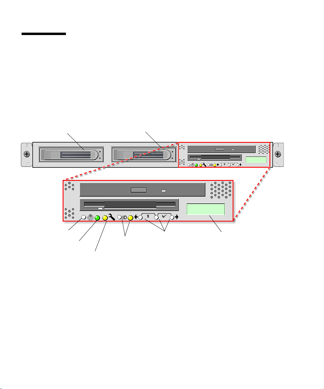
1.4.1 Front and Back Panels
Hard disk drive 2
Platform power
button
Platform power
indicator LED
FIGURE 1-1
Front Panel
FIGURE 1-1
illustrates the front panel of the Sun Fire V20z server.
Hard disk drive 1
System fault
LED
Locate button
and LED
Operator panel
buttons
Operator panel
LCD display
Refer to “Operator Panel” on page 1-5 for more information about the operator
panel.
1-4
Sun Fire V20z Server User Guide • March 2004
Page 15
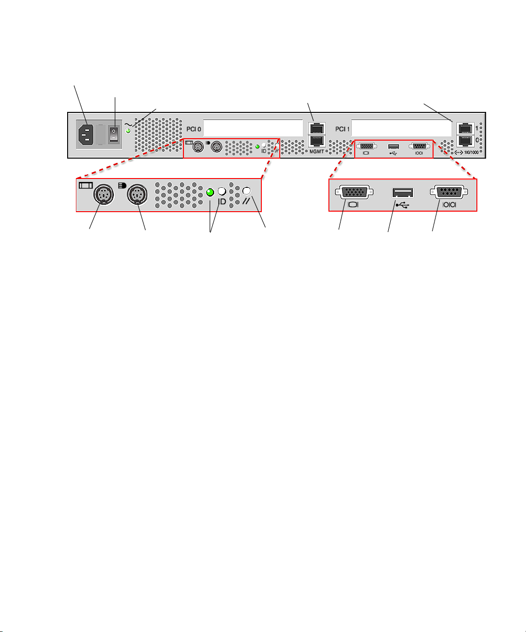
FIGURE 1-2
depicts the back panel of the Sun Fire V20z server:
AC power connector
AC power switch
AC power indicator LED
Keyboard Mouse
connector connector
FIGURE 1-2
Back Panel
Locate button
and LED
1.4.2 Operator Panel
You can use the operator panel to configure network settings for the service
processor.
FIGURE 1-1
shows where the operator panel is located on the front panel.
SP reset
button
SP 10/100
Ethernet
connectors
Video
connector
Platform Gigabit
Ethernet
connectors
USB
connector
Serial port
connector
The drivers for the Sun Fire V20z server must be installed to access these menu
options. Some operator panel menus are only functional under these conditions:
An external file system is configured with the Network Share Volume.
■
■
The service processor update server from the Network Share Volume machine is
available.
The machine has Java Runtime Environment 1.4.1 installed on it.
■
The liquid-crystal display (LCD) panel on the operator panel displays menu options
with
Menu:
appearing in the first line and the menu option in the second line. When
no menu option is available, the first line displays SP information, such as the
IP address, and the second line provides platform information. For example:
123.45.67.89
OS running
Chapter 1 Introduction to the Sun Fire V20z Server
1-5
Page 16
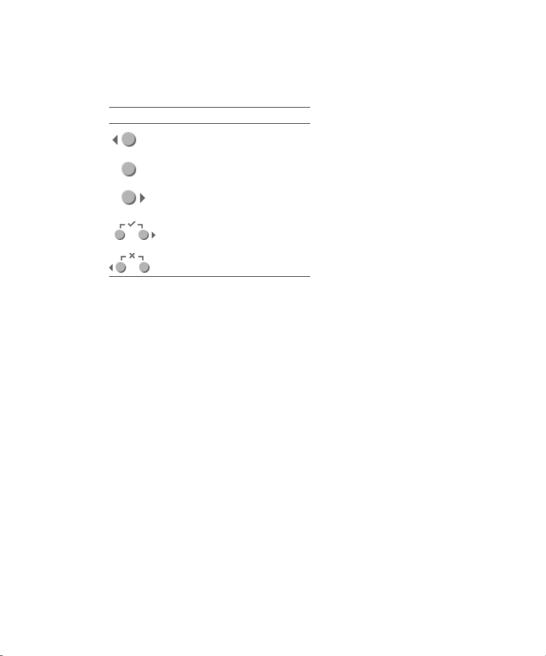
TABLE 1-2
shows the operator panel buttons that are used to navigate through the
menu options.
TABLE 1-2
Button Function
Operator Panel Buttons
Back/No
Select
Forward/Yes
Enter
Cancel
The Back/No and Forward/Yes buttons automatically scroll, repeating the action as
long as the button is held down. After the button is held down a few seconds, auto
scrolling begins and rapidly increments or decrements the value.
If a menu or data entry screen displays for more than 30 seconds with no action
taken, the menu or data entry is cancelled and the display returns to the
idle/background state.
1-6
Sun Fire V20z Server User Guide • March 2004
Page 17

TABLE 1-3
lists the operations you can perform from the operator panel:
TABLE 1-3
Menu Menu Options Description
Operator Panel Menu Options
Server Shutdown server Signals the server operating system to shut down and
power off.
To force the power off in the case where the operating
system hangs, the operator must hold the power button for
four seconds.
Reboot server Signals the server operating system to shut down and
reboot.
Display Port 80 Displays the last ten Port 80 codes (in hex, 5 per line). Press
any button to clear the display. The display automatically
clears after 30 seconds.
This feature only works in BIOS booting state; to see all the
post codes run the
sp get port80 -m
command.
Panel Use SP hostname Displays the service processor’s networking hostname in
the top line instead of its numeric IP address.
Name for LCD Displays a custom name for the service processor in the
LCD. (For more information, refer to
Installation Guide
, 817-5246-xx.)
Sun Fire V20z
Clear LCD name Removes the user-specified name for the service processor.
Either the hostname or the IP address displays in the first
line.
Rotate IP/Name The first line of the LCD alternates every five seconds. For
example, the custom name for the LCD or hostname
displays, then the IP address, then back, and so on every
five seconds.
If you set the Name for LCD, it displays in the top line. If
you do not set the Name for LCD and you do specify the
Use SP hostname, the hostname displays in the top line. If
you specify neither the Name for LCD or the Use SP
hostname options, the numeric IP address displays.
SP Set SP IP
information
Configures the service processor network using DHCP or a
static IP address. (For more information, refer to
V20z Installation Guide
, 817-5246-xx.)
Sun Fire
Auto Configure Propagates configuration information to the service
processor. (For more information, refer to
Installation Server Management Guide,
Sun Fire V20z
817-5249-xx.).
Update SP Updates service processor software. (For more information,
refer to
Guide,
Sun Fire V20z Installation Server Management
817-5249-xx.)
Chapter 1 Introduction to the Sun Fire V20z Server
1-7
Page 18

TABLE 1-3
Menu Menu Options Description
Operator Panel Menu Options
Dump SP Invokes the Troubleshooting Dump Utility (TDU) which
captures the following information and either sends it to
stdout or stores it in an output file:
• system state table (SST)
• hardware and software component versions
• machine check register values
• CPU trace buffers
• CPU configuration space registers (CSR)
• event log file
• the last good configuration (LGC)
By default, the TDU data is redirected to stdout. If you do
not provide a filename, the output is sent to stdout and the
log files are not created.
Otherwise, you can use this option to specify the name of
the output file to which the log files are copied. Storing to a
file is only available if you have configured an external file
system.
You can also invoke the TDU using the
command.
Use defaults Restores service processor settings to the default factory
configuration.
lost and the service processor is rebooted.
Reboot SP Forces the service processor to shut down and reboot.
Note:
The platform operating system is not affected.
(Continued)
sp get tdulog
Note:
All current data (network, users) is
1-8
Sun Fire V20z Server User Guide • March 2004
Page 19

1.4.3 Front and Back Panel LEDs
TABLE 1-4
TABLE 1-5
FIGURE 1-2
TABLE 1-4
LED Description
Platform Power This LED is lit when the platform power is on.
System Fault This LED blinks when a severe system fault, such as an overvoltage
Locate This LED is lit when you press the Locate button on either the front
TABLE 1-5
LED Description
AC Power Indicator This LED is lit when the AC power is on.
Locate This LED is lit when you press the Locate button on either the front
describes the LEDs on the front panel of the Sun Fire V20z server, and
describes the LEDs on the back panel of the server. Refer to
FIGURE 1-1
for the locations of these LEDs.
Front Panel LEDs
condition or an upper temperature limit, is detected. See
“Troubleshooting and Diagnostics” on page 3-1 for information on
troubleshooting the system.
or the back of the server. This LED helps you to identify which
system in the rack you are working on.
Back Panel LEDs
or the back of the server. This LED helps you to identify which
system in the rack you are working on.
and
Chapter 1 Introduction to the Sun Fire V20z Server
1-9
Page 20
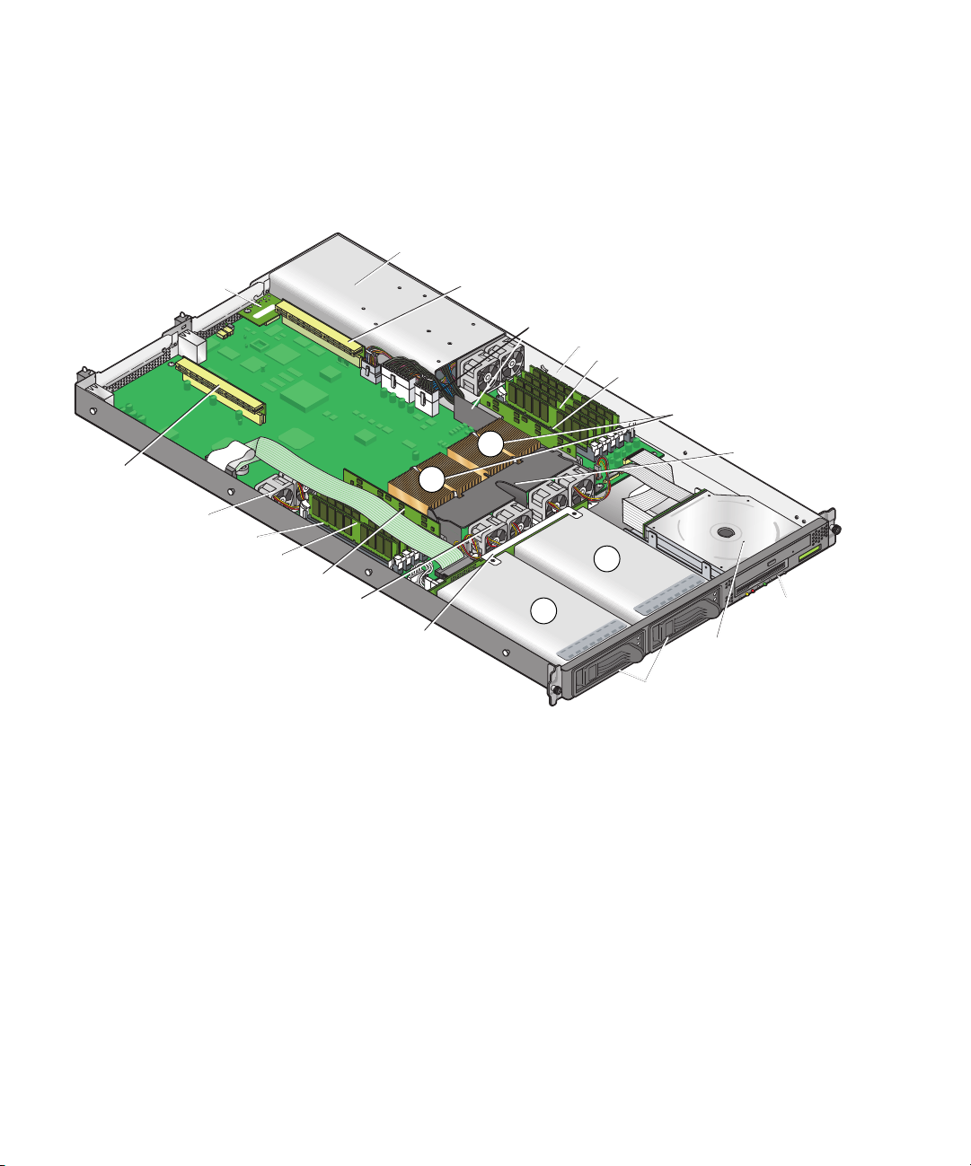
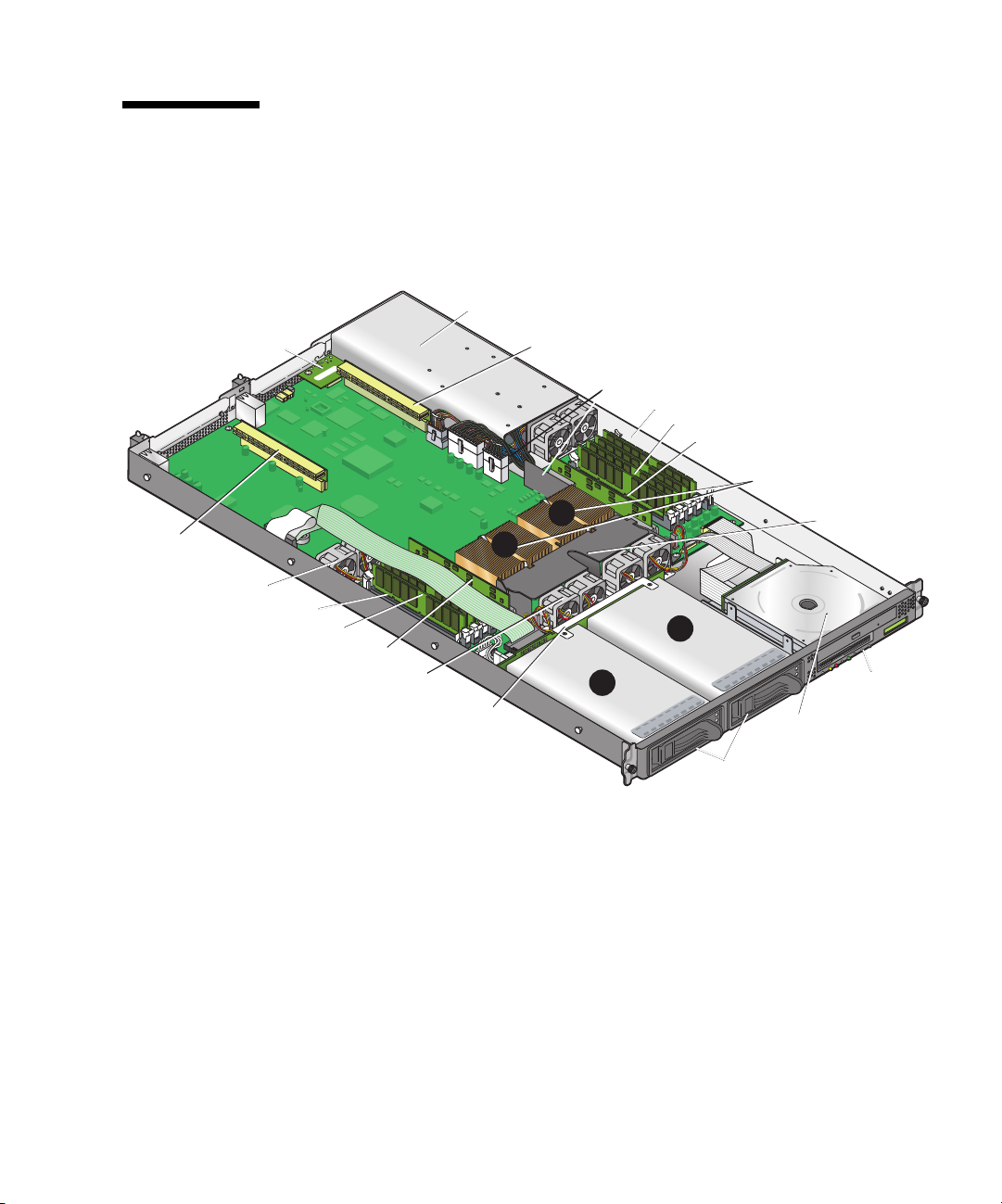
1.4.4 System Components
PCI Riser
(half length)
FIGURE 1-3
chassis.
I/O
Board
Fans (2)
Memory VRM
Memory Modules
shows the locations of the components inside the Sun Fire V20z server
Powe r
Supply
PCI Riser
(full length)
Side Air
Baffle
Memory VRM
Memory Modules
CPU VRM
CPUs and Heatsinks (2)
0
Center
Air Baffle
1
1
CPU VRM
Fans (4)
SCSI
Backplane
HD bays (2)
2
CD/DVD-FD
Drive Module
SCSI HDDs
with Carriers
Operator
Panel and
LCD
FIGURE 1-3
1-10
System Components
Sun Fire V20z Server User Guide • March 2004
Page 21

1.5 Ship Kit
The Sun Fire V20z server is supplied with the components shown in Table 1-6.
TABLE 1-6 Contents of the Sun Fire V20z Server Ship Kit
Item Part Number Quantity Delivery
Sun Fire V20z Server Documentation and Resource
CD, containing the following documents:
• Sun Fire V20z Server Installation Guide
• Sun Fire V20z Server Operating System Installation
Guide
• Sun Fire V20z Server User Guide
• Sun Fire V20z Server Management Guide
• Sun Fire V20z Server Release Notes
Sun Fire V20z Server Network Share Volume CD 705-0970 1 CD
Sun Fire V20z Server Warranty and Disclaimer 817-5246 1 Printed
Setting Up the Sun Fire V20z Server 817-5336 1 Printed
Important Safety Information for Sun Hardware Systems 816-7190 1 Printed
Sun Fire V20z Server 602-2637-01 1 In box
Power Cord (for USA) none 1 In box
705-0971
817-5246
817-5250
817-5248
817-5249
817-5252
1CD
1.6 Replaceable Components
Sun offers additional hard disk drives and memory modules for the server.
The replaceable components on the Sun Fire V20z server are shown in
order
them, contact your local Sun sales representative.
You may have a part that is replaceable under warranty. For specific details
regarding your warranty, refer to:
See
http://www.sun.com/service/support/warranty/index.html
Chapter 1 Introduction to the Sun Fire V20z Server
TABLE 1-7
. To
1-11
Page 22

TABLE 1-7 Sun Fire V60x Server Replaceable Components
Component Part Number
CPU/Heatsink Kit
• Opteron 242, 1.6 GHz
• Operton 244, 1.8 GHz
• Opteron 248, 2.2 GHz
595-7376-01
595-7336-01
595-7337-01
Memory
•1 GB ECC DDR/333 (2 x 512 MB DIMMs)
•2 GB ECC DDR/333 (2 x 1 GB DIMMs)
•4 GB ECC DDR/333 (2 x 2 GB DIMMs)
595-7339-01
595-7340-01
595-7341-01
Hard disk drives (HDDs)
• 36 GB, Ultra 320 SCSI, 10K rpm
•73 GB, Ultra 320 SCSI, 10K rpm
595-7342-01
595-7344-01
Floppy/CD-ROM combo unit 595-7347-01
Floppy/DVD combo unit 595-7348-01
Ultra SCSI 320 dual port PCI-X card, full length card 595-7353-01
FC-AL 2 Gb/s PCI-X card, low profile 133 MHz card 595-7377-01
Single Gigabit Ethernet PCI-X NIC, low-profile 66 or
595-7359-01
133 MHz card
Dual Gigabit Ethernet PCI-X NIC, low-profile 66 or
595-7360-01
133 MHz card
Quad Gigabit Ethernet PCI-X NIC, low-profile 66 or
595-7361-01
133 MHz card
Rail rackmount kit 595-7378-01
478W power supply F370-6636-01
Fan assembly F370-6639-01
CPU Voltage Regulator Module (VRM) F370-6680-01
Memory Voltage Regulator Module (VRM) F370-6646-01
SCSI backplane F370-6647-01
Server Super FRU F370-0979-01
Operator panel F370-6681-01
Cable assembly F370-6676-01
I/O board F370-6678-01
PCI riser card F370-6679-01
1-12 Sun Fire V20z Server User Guide • March 2004
Page 23

1.7 Integrated Mirroring
With traditional mirroring (or RAID1), a drive has its data duplicated on two
different drives using either a hardware RAID controller or software (generally by
means of the operating system). If either drive fails, the other continues to function
as a single drive until the failed drive is replaced.
With integrated mirroring enhanced (IME) (also referred to as either Enhanced
RAID1 or RAID1E), instead of only being able to use only two drives, you can use
two to six drives, including the option of only using an odd number of drives.
Instead of mirroring at the disk level, the data is mirrored in stripes across the
drives. Thus, IME allows for more flexibility with mirroring data.
Not all operating systems support RAID on the Sun Fire V20z server at this time.
Refer to the Sun Fire V20z Server Release Notes,
operating systems do not yet support the Sun Fire V20z RAID capabilities.
817-5252-xx, for information on which
Chapter 1 Introduction to the Sun Fire V20z Server 1-13
Page 24

1-14 Sun Fire V20z Server User Guide • March 2004
Page 25

CHAPTER
2
Powering On and Configuring the
Server
This chapter contains instructions on powering up and configuring the server BIOS.
Before powering on the server for the first time, follow the instructions in the Sun
Fire V20z Server Installation Guide,
This chapter contains the following sections:
■ “Powering On the Server” on page 2-1
■ “Escape Sequences for Remote Console Terminal” on page 2-3
■ “BIOS Setup Utility” on page 2-4
■ “Booting to a USB Diskette Device” on page 2-16
817-5246-xx, to set up your server.
2.1 Powering On the Server
Before powering on the server for the first time, follow the setup instructions in the
Sun Fire V20z Server Installation Guide,
If you do not have an operating system installed on the server, you will need to use
a PS/2 keyboard for initial bootup. USB support is disabled in the BIOS by default.
See “BIOS Setup Utility” on page 2-4 for more information.
Caution – Do not operate this server without all fans, component heatsinks, and air
baffles installed. Severe damage to server components will occur if the server is
operated without adequate cooling mechanisms.
817-5246-xx.
2-1
Page 26

Follow these steps to boot the server:
1. Ensure that the AC power cord is plugged into the power connector on the rear of
the server and into a power outlet.
2. Turn on the power switch on the back of the system to power on the service
processor.
When the service processor is active, you can perform all configuration tasks
without turning on the main power in Step 3.
Note – If this is the first time you are booting the server, you may have to wait
approximately two to five minutes for the service processor to boot.
3. When the Operator Panel LCD shows the message Main Power Off, press the
platform power button on the front of the server in order to install or access the
operating system.
Refer to the Sun Fire V20z Server Operating System Installation Guide,
information on installing the operating system.
When the system begins booting up, the power on self test (POST) will run.
817-5250-xx, for
Note – If the POST encounters any error while it is running, it will pause and you
will need to press the F1 key to continue.
4. When prompted, you can press the F2 key to enter the BIOS Setup Utility or press
the F12 key to boot from the network. To boot from the default boot device, let the
prompt time out and the boot process will continue.
For further information on the BIOS Setup Utility, refer to “BIOS Setup Utility” on
page 2-4. For information on setting up a network PXE installation, see the Sun Fire
V20z Sever Operating System Installation Guide,
817-5250-xx.
2.2 Powering Off the Server
To perform a graceful shutdown of the server running a Linux or Unix operating
environment, type the following command:
# power off
This command shuts down the operating system. Depending on which operating
system you are using, you may also have to manually push the platform power
button after the operating system shuts down.
2-2 Sun Fire V20z Server User Guide • March 2004
Page 27

2.3 Escape Sequences for Remote Console Terminal
If you are accessing your Sun Fire V20z server using a remote console terminal, you
may need to use the escape sequences shown in
is not working properly, use the escape sequence listed next to it in the table.
You will most likely need to use the escape sequences if you are using a Linux or
Solaris operating system.
TABLE 2-1 Special Keys for Remote Console Terminal
Function Key Escape Sequence
HOME <ESC> h
END <ESC> k
INSERT <ESC> +
DELETE <ESC> -
PAGE UP <ESC> ?
PAGE DOWN <ESC> /
ALT <ESC>^A
CTRL <ESC>^C
F1 <ESC> 1
F2 <ESC> 2
F3 <ESC> 3
F4 <ESC> 4
F5 <ESC> 5
F6 <ESC> 6
F7 <ESC> 7
F8 <ESC> 8
F9 <ESC> 9
F10 <ESC> 0
F11 <ESC> !
F12 <ESC> @
TABLE 2-1. If a regular function key
Chapter 2 Powering On and Configuring the Server 2-3
Page 28

2.4 BIOS Setup Utility
The Basic Input Output System (BIOS) Setup utility is used to configure BIOS
settings. When the computer is powered on, it is configured with the values stored
in the BIOS ROM by the system BIOS, which gains control at boot time.
To change the system parameters, enter the BIOS Setup utility by pressing the F2 key
when prompted as the system is booting up.
To access the BIOS Setup utility remotely, you can log in by means of an SSH client.
Refer to the Sun Fire V20z Server Management Guide,
about managing the server remotely.
Note – If you are using a USB keyboard, the F2 key may not work properly when
entering BIOS Setup unless the F-Lock key is on.
From the Main setup screen, you can access other setup screens, such as Security and
Power. The tables in the following sections describe each parameter setting in the
Setup Utility.
To navigate between items in a menu:
■ Use the up and down arrow keys to move among the settings in each menu.
■ Use the left and right arrow keys to change the options for each setting.
Items that include submenus begin with a triangle icon. To access a submenu, select
the item so that it is highlighted and press Enter.
817-5249-xx, for more information
2-4 Sun Fire V20z Server User Guide • March 2004
Page 29

2.4.1 Main Menu
TABLE 2-2 shows the options that are available from the BIOS Main menu.
TABLE 2-2 BIOS Main Menu
Menu Option Description Default
System
Time
System
Date
Legacy
Diskette A
Legacy
Diskette
Enter the system time (hours:minutes:seconds) in the
specified fields and press Enter to save the data. Use
the Tab key to move to the next field and use
Shift+ Tab to move to the previous field.
Enter the current date in the month, day, and year
fields. Press Enter to save the data. Use the Tab key
to move to the next field and use Shift + Tab to move
to the previous field.
Set the type of floppy disk drive installed as diskette
A. Options include: Disabled, 360Kb 5.25 in, 1.2MB
5.25 in, 720Kb 3.5 in, 1.44/1.25MB 3.5 in, and 2.88MB
3.5 in.
Note: 1.44/1.25MB 3.5 references a 1024 byte sector
Japanese media format. This diskette requires a
3-mode floppy disk drive.
Sets the type of floppy disk drive installed as
diskette B. Options include: Disabled, 360Kb 5.25 in,
1.2MB 5.25 in, 720Kb 3.5 in, 1.44/1.25MB 3.5 in, and
2.88MB 3.5 in.
Note: 1.44/1.25MB 3.5 references a 1024 byte sector
Japanese media format. This diskette requires a 3mode floppy disk drive.
Current time
Current date
1.44/1.25 MB
3.5 in.
Disabled
Chapter 2 Powering On and Configuring the Server 2-5
Page 30

TABLE 2-2 BIOS Main Menu (Continued)
Menu Option Description Default
Primary
Master
Set the parameters of the IDE Primary Master/Slave
and IDE Secondary Master slots. Press Enter to
activate the submenu screen to configure each of
Primary
Slave
Secondary
Master
these settings. The submenu options include:
• Type: The type of IDE hard drive. Options include:
Auto (allows BIOS to automatically determine the
hard drive’s capacity, number of heads, etc.), User,
a number from 1 to 39 to select a predetermined
Auto
Multisector
type of hard drive, CD-ROM, ATAPI Removable,
and IDE Removable.
• Multi-Sector Transfers: The number of transfer
Disabled
sectors. Options include: Disabled, 2, 4, 8, and 16
sectors.
• LBA Mode Control: Determines whether BIOS will
Disabled
access the IDE Primary Master Device via LBA
mode. Options include: Enabled and Disabled.
• 32-bit I/O: Selects the 32-bit I/O operation. Options
Disabled
include: Enabled and Disabled.
• Transfer Mode: Selects the transfer mode.
Standard
Options include: Standard, Fast PIO1, Fast PIO2,
Fast PIO3, Fast PIO4, FPIO3/DMA1, and
FPIO4/DMA2.
• Ultra DMA Mode: Selects Ultra DMA Mode.
Disabled
Options include: Disabled, Mode 0, Mode 1, Mode
2, Mode 3, Mode 4, Mode 5, and Mode 6.
HDD Post
Enable or disable HDD Post Write Buffer support. Enabled
Write
Buffer
Large Disk
Access
Mode
For UNIX, Novell Netware, or other operating
systems select Other. If you are installing new
software and the drive fails, change this selection
DOS
and try again. Different operating systems require
different representations of drive geometries.
Options include: DOS and Other.
Boot
Summary
System
Memory
Extended
Memory
Enable or disable display of the system configuration
on boot.
Displays how much system memory is recognized as
present in the system.
Displays how much extended memory is recognized
as present in the system.
Disabled
Current
memory
Current
memory
2-6 Sun Fire V20z Server User Guide • March 2004
Page 31

2.4.2 Advanced Menu
TABLE 2-3 shows the options that are available from the Advanced menu.
TABLE 2-3 BIOS Advanced Menu
Menu Option Description Default
Reset
Configuration
Data
Multiprocessor
Specification
PCI Interrupts
From MP Table
Machine Check
Stop
QuickBoot
Mode
SRAT Table Enables the ACPI 2.0 Static Resource Affinity Table
Node
Interleave
Bank Interleave If set to Auto, bank interleaving is enabled if the
Clears the Extended System Configuration Data
(ECSD). Options include: Yes and No.
Configures the MP Specification revision level. Some
operating systems require 1.1 for compatibility.
Options include: 1.4 and 1.1.
Configures the MP Table with PCI Interrupt entries.
Options include: Yes and No.
If enabled, system stops when a machine check error
occurs. If disabled, system reboots when a machine
check error occurs. Only applies if your operating
system does not have its own machine check handler.
Allows the system to skip tests while booting.
Options include: Enabled and Disabled.
for operating systems that support an SRAT and will
disable node interleaving. Disabled allows for node
interleaving. Options include: Enabled and Disabled.
If set to Auto, node interleaving is enabled if
memory sizes match and if SRAT table is disabled.
Options include: Auto and Disabled.
memory size and type match. Options include: Auto
and Disabled.
No
1.4
Ye s
Disabled
Disabled
Enabled
Disabled
Auto
Chapter 2 Powering On and Configuring the Server 2-7
Page 32

TABLE 2-3 BIOS Advanced Menu (Continued)
Menu Option Description Default
Chipset
Configuration
Caution: Don’t
change the
settings unless
you are sure of
what you are
doing. Setting
items on this
menu to
incorrect values
may cause your
system to
malfunction.
Options for advanced chipset features. Options
include:
• ECC: Enable or disable ECC check/correct mode.
This is a global enable function for all blocks
within the CPU core and North Bridge.
• DRAM ECC: If all memory in the system supports
ECC (x72), enabling invokes initial scrub DRAM
and enables system requests to DRAM to be
checked and/or corrected. Options include:
Enabled and Disabled.
• ECC Scrub Redirection: Enable or disable EDD
Scrubber to correct errors detected in DRAM
during normal CPU requests (foreground
Enabled
Enabled
Enabled
scrubbing).
• Chip-Kill: Enabled or disable the ChipKill ECC on
Enabled
nodes with all x4 ECC capable DIMMS.
• DCACHE ECC Scrub CTL: Sets the rate of
5.12 us
background scrubbing for DCACHE lines. Options
include: 5.12 µs, 10.2 µs, 20.5 µs, 41.0 µs, Disabled,
640 nx, 1.28 µs, 2.56 us.
• L2 ECC Scrub CTL: Sets the rate of background
10.2 us
scrubbing for L2 cache lines. Options include: 10.2
us, 20.5 µs, 41.0 µs, 81.9 µs, Disabled, 1.28 µs,
2.56 µs, 5.12 µs.
• DRAM ECC Scrub CTL: Sets the rate of background
163.8 us
scrubbing for DRAM (in addition to normal ECC
scrubbing from system requests). Background
agent works independently of CPU requests and
bus masters, but cannot be enabled without first
enabling DRAM ECC. Options include: 163.8 us,
327.7 µs, 655.4 µs, 1.31 ms, Disabled, 20.5 µs, 41.0
us, 81.9 µs.
• SRAT Table: Enables the ACPI 2.0 Static Resource
Enabled
Affinity Table for operating systems that support
an SRAT and will disable node interleaving.
Disabled allows for node interleaving. Options
include: Enabled and Disabled.
• Node Interleave: If set to Auto, node interleaving
Disabled
will be enabled if memory sizes match and if SRAT
table is disabled. Options include: Auto and
Disabled.
2-8 Sun Fire V20z Server User Guide • March 2004
Page 33

TABLE 2-3 BIOS Advanced Menu (Continued)
Menu Option Description Default
• Bank Interleave: If set to Auto, bank interleaving is
Auto
enabled if the memory size and type match.
Options include: Auto and Disabled.
Keyboard
Configuration
Options for keyboard feature menu. Options include:
• Numlock: Selects Power-on state for Numlock.
Auto
Options include: Auto, On, Off.
• Keyboard Auto-Repeat Rate: Selects the key repeat
30/sec
rate. Options include: 30/sec, 26.7/sec, 21.8/sec,
18.5/sec, 13.3/sec, 10/sec, 6/sec, 2/sec.
• Keyboard Auto-Repeat Delay: Selects delay before
1/2 sec
key repeat. Options include: 1/2 sec, 3/4 sec, 1 sec,
1/4 sec.
Chapter 2 Powering On and Configuring the Server 2-9
Page 34

TABLE 2-3 BIOS Advanced Menu (Continued)
Menu Option Description Default
I/O Device
Configuration
Options for peripheral menu. Options include:
• PS/2 Mouse: Disabled prevents any installed PS/2
Enabled
mouse from functioning, but frees up IRQ 12.
Enabled forces the PS/2 mouse port to be enabled
regardless of whether a mouse is present. Auto
Detect enables the PS/2 mouse only if present. OS
Controlled only displays if the OS controls the
mouse.
• Floppy Disk Controller: Options include: Enabled
Enabled
(user configuration), Disabled (no configuration),
Auto (BIOS or OS chooses configuration), and OS
Controlled (displayed when controlled by the
operating system).
USB Host Controller: Enables or disables the USB
Enabled
hardware. Disabled resources are freed for other
users.
USB BIOS Legacy Support: Enables or disables
Disabled
support for USB devices. Enable for use with a nonUSB aware operating system such as DOS, Linux or
Solaris.
• Onboard PCI IDE: Enables the integrated local bus
IDE: Both
IDE adapter. Options include: Disabled, Primary,
Secondary, Both.
• Serial Port A: Assigns control of serial port A.
Disabled
Options include: Enabled, Auto, or Disabled.
When enabled, you must also select the Base I/O
Address (options are 3F8, 2F8, 3E8, and 2E8) and
Interrupt (options are IRQ3 and IRQ4) for serial
port A.
• Ethernet Adapter 1 MAC: Displays the Onboard
MAC address
Ethernet Adapter 1 MAC address.
• Ethernet Adapter 2 MAC: Displays the Onboard
MAC address
Ethernet Adapter 2 MAC address.
2-10 Sun Fire V20z Server User Guide • March 2004
Page 35

TABLE 2-3 BIOS Advanced Menu (Continued)
Menu Option Description Default
PCI
Configuration
Setup items for configuring the specific PCI device
Slot #1 or Slot #2:
• Option ROM Scan: When disabled, the device is not
Enabled
bootable but still usable under the operating
system. When enabled, initializes the device
expansion ROM; makes device bootable.
• Enable Master: Enables or disables the selected
Enabled
device as a PCI bus master.
• Latency Timer: Minimum guaranteed time slice
0040h
allotted for bus master in units of PCI bus clocks.
Options include: 0040h, 0060h, 0080h, 00AOh,
00COh, 00EOh, default, and 0020h.
Setup items for configuring the Embedded Broadcom
device GBIT 0 or GBIT 1:
• Option ROM Scan: When disabled, the device is not
Enabled
bootable but still usable under the operating
system. When enabled, initializes device
expansion ROM; makes device bootable.
Reserve specific IRQs for use by legacy ISA devices:
• PCI/PNP IRQ Exclusion: Reserves the specified IRQ
Available
for use by legacy ISA devices.
• PCI/PNP UMB Exclusion: Reserves the specified
Available
block of upper memory for use by legacy ISA
devices.
Console
Redirection
Additional setup to configure console. Options
include:
• COM port address: If enabled, the console uses a
COM A
port on the motherboard. Options include:
Disabled, On-board COM A, On-board COM B.
• Console connection: Indicates whether the console is
Direct
connected directly to the system or through a
modem. Options include: Direct and Modem.
• Baud rate: Enables the specified baud rate. Options
9600
include: 300, 1200, 2400, 9600, 19.2K, 38.4 K, 57.6K,
115.2 K.
Chapter 2 Powering On and Configuring the Server 2-11
Page 36

TABLE 2-3 BIOS Advanced Menu (Continued)
Menu Option Description Default
• Flow control: Enables flow control. Options include:
None, XON/XOFF, CTS/RTS.
• Console type: Enables the specified console type.
Options include: VT100, VT100 8 bit, ANSI 7 bit,
ANSI VT100 plus, VTF8.
• Continue CR after POST: Normally, console
redirection is off before the operating system
loads. Set this item to on to troubleshoot the BIOS
boot problems. Note: the operating system loader
typically interrupts console redirection once it
starts. Options include: On and Off.
2.4.3 Security Menu
TABLE 2-4 shows the options that are available from the BIOS Security menu.
TABLE 2-4 BIOS Security Menu
Menu Option Description Default
Supervisor
Password Is:
User Password
Is:
Set Supervisor
Password
Displays whether a supervisor password has
been entered for the system. Clear means
such a password has not been used and Set
means a supervisor password has been
entered for the system.
Displays whether a user password has been
entered for the system. Clear means such a
password has not been used and Set means a
user password has been entered for the
system.
Supervisor password controls access to the
Setup Utility. Enter the Supervisor’s
password to set or change it. Enables access
to BIOS.
None
ANSI
Off
Clear
Clear
Enter
2-12 Sun Fire V20z Server User Guide • March 2004
Page 37

TABLE 2-4 BIOS Security Menu (Continued)
Menu Option Description Default
Set User
Password
Password on
Boot
Fixed Disk Boot
Sector
Enter the user’s password to set or change it.
Enables access to the system at boot time.
Allows you to require a password to be
entered when the system boots. Options
include: Enabled (password required) and
Disabled (password not required).
May offer protection against viruses when
set to Write Protect, which protects the boot
sector on the hard drive from having a virus
written to it. Options include: Write Protect
and Normal.
2.4.4 Power Menu
TABLE 2-5 shows the options that are available from the BIOS Power menu.
TABLE 2-5 BIOS Power Menu
Menu Option Description Default
Resume on
Time
Resume Time If turned on, specifies the time you want the system
Resume Date If turned on, specifies the date you want the system
After Power
Failure
Wakes the system up at the specified time. Options
are On or Off.
to wake up.
to wake up.
Sets the mode of operation if an AC power loss
occurs. Two modes are available:
Stay powered off: returns the system to an off state.
Power on: returns the system to a full on state.
Last state: returns the server to the state it was at
before the power went off.
Enter
Disabled
Normal
Off
00.00.00
00/00/0000
Stay powered
off
Chapter 2 Powering On and Configuring the Server 2-13
Page 38

2.4.5 Boot Menu
TABLE 2-6 shows the options that are available from the BIOS Boot menu. To change
the order of the boot items, select an item and press the plus (+) key to move the
item up in the order and the minus (-) key to move the item down in the order.
TABLE 2-6 BIOS Boot Menu
Menu Option Description Default Boot Order
Removable Devices (Floppy) Boot from the floppy drive First boot device
CD-ROM Drive Boot from the CD-ROM Second boot device
Hard Disk Boot from the hard disk Third boot device
MBA v7.0.1 Slot 0210 Boot from the on-board NIC #1 Fourth boot device
MBA v7.0.1 Slot 0218 Boot from the on-board NIC #2 Fifth boot device
2.4.6 Exit Menu
TABLE 2-7 shows the options that are available from the BIOS Exit menu.
TABLE 2-7 BIOS Exit Menu
Menu Item Description
Exit Saving
Changes
Exit Discarding
Changes
Load Setup
Defaults
Discard
Changes
Save Changes Save setup data to CMOS.
Exit System Setup and save changes to CMOS.
Exit System Setup without saving changes.
Load defaults for all setup items.
Load previous values from CMOS for all setup items.
2-14 Sun Fire V20z Server User Guide • March 2004
Page 39

2.4.7 Quick Boot Feature
The QuickBoot feature, which disables BIOS memory tests, defaults to disabled,
which is the recommended setting.
If you choose to set Quickboot to enabled, you need to perform the following steps
to disable the QuickBoot feature whenever you add new memory, so that the new
memory configuration can be tested.
1. Boot the server and run BIOS Setup by pressing the F2 key during the boot
process.
2. From the Advanced menu, disable the QuickBoot option.
Now the BIOS will run at least one full memory test for your new memory when the
server is rebooted.
3. Press F10 to save the changes and exit.
The system will automatically reboot and run the memory configuration tests.
4. When all memory passes the tests, press the F2 key to enter BIOS Setup and reenable the QuickBoot option in the BIOS Advanced menu, if needed.
Chapter 2 Powering On and Configuring the Server 2-15
Page 40

2.5 Booting to a USB Diskette Device
Only one diskette device is bootable on the Sun Fire V20z server. By default, the
internal diskette device is the only device from which you can boot.
To change the assignment of the diskette devices so that the server boots from the
USB diskette device, rather than the internal diskette device, perform the following
steps:
1. Attach the USB diskette device.
2. Power on and reboot the system.
3. Press the F2 key to enter the BIOS Setup utility.
4. From the Advanced menu, choose I/O Device Configuration.
5. Change the USB Host Controller and USB BIOS Legacy Support submenu options
to Enable.
6. Press the F10 key to save your changes and reboot the server.
7. When prompted, press the F2 key to enter the BIOS Setup utility.
8. In the Boot menu, select Removable Devices.
9. Select USB Floppy from the Removable Devices submenu, and press the plus (+)
key to move USB Floppy to the top of the list of devices.
10. Press the F10 key to save your changes and reboot.
The USB diskette device is bootable as drive A. If left enabled, the internal floppy
becomes drive B and is not bootable.
Note – To change the internal diskette device to drive A again, disconnect the USB
diskette device and reboot the server. The internal diskette device will be assigned to
drive A, and if you reattach the USB diskette device, it will be assigned to drive B.
2-16 Sun Fire V20z Server User Guide • March 2004
Page 41

CHAPTER
3
Troubleshooting and Diagnostics
Before troubleshooting your specific server problem, collect the following
information:
■ What events occurred prior to the failure?
■ Was any hardware or software modified or installed?
■ Was the server recently installed or moved?
■ How long has the server exhibited symptoms?
■ What is the duration or frequency of the problem?
The guidelines in “Preventative Troubleshooting” on page 3-2 will help you to
prevent problems from occurring and will make troubleshooting easier.
After you have assessed the problem and noted your current configuration and
environment, you can choose from several ways to troubleshoot your Sun Fire
V20z server
■ Visually inspect your system as described in “Visually Inspecting Your System”
on page 3-3.
■ Execute the Troubleshooting Dump Utility as described in “Troubleshooting
Utility” on page 3-5.
■ Execute diagnostics tests as described in “Diagnostics” on page 3-5.
:
3-1
Page 42

3.1 Preventative Troubleshooting
Creating and following procedures can help prevent problems and make
troubleshooting easier.
Follow these guidelines for preventative troubleshooting:
■ Use uniform naming conventions for your servers, such as names that denote server
location. Uniform naming conventions help when you try to remember often
overlooked details that can hold the key to resolving a crisis.
■ Use unique IDs or names for your devices. You can reduce the risk of components
competing for the same resource if you have a list. Use the server setup utility to
check for conflicts.
■ Create a backup plan. Schedule backups based on the needs of your server. If data is
changed frequently, frequent backups are required. Maintain a library of backups
based on your information restoring needs. Test your backups periodically to be
sure that your data is correctly stored.
■ Use enterprise systems management tools to automate the following processes, or
manually track this information:
■ Check hard disk space periodically. It is recommended that hard drives have a
minimum of 15 percent of free space.
■ Keep historical data. You will not know that the CPU utilization has increased
50 percent if you do not know what it was initially. If you have problems, you
can use the data to compare before and after scenarios. For example, you might
want to know about the user, bus, and power utilization rates.
■ Keep a trend analysis so that you will know what to expect during certain
points in time. For example, if the CPU utilization rate always increases by 50
percent during certain hours, you will know that increase is normal for the
server you are tracking.
■ Create a problem resolution notebook. When problems do occur, keep a log of the
actions you took to resolve them. This could help you solve the same problem
more quickly in the future. This information can save a great deal of time in the
future and ensure accuracy, especially when dealing with future part replacement.
■ Keep an updated network topology map in an accessible location. This will help
in troubleshooting networking problems.
3-2 Sun Fire V20z Server User Guide • March 2004
Page 43

■ Most problems occur when something in the server has changed. When making
changes to your server, follow these guidelines:
■ Document the system settings. If the system configuration will change, first
obtain a record of the current system configuration settings.
■ If possible, make changes one at a time to isolate problems if they should occur.
This enables you to maintain a controlled environment and reduces the scope
of any troubleshooting. Record the results of each change, including any errors
or informational messages.
■ Check for potential device conflicts before adding a new device. Check for any
potential version dependencies, especially with third party software.
3.2 Visually Inspecting Your System
Improperly set controls and loose or improperly connected cables are common
causes of problems with hardware components. When investigating a system
problem, first check all the external switches, controls, and cable connections.
See “External Visual Inspection” on page 3-3.
If this does not resolve your problem, then visually inspect the system’s interior
hardware for problems such as a loose card, cable connector, or mounting screw. See
“Internal Visual Inspection” on page 3-4.
3.2.1 External Visual Inspection
To visually inspect the external system, follow these steps:
1. Note the state of the system fault LED on the front of the server.
The system fault LED blinks when a severe system fault, such as an overvoltage
condition or an upper temperature limit, is detected. See
of the system fault LED.
2. Turn off the system and any attached peripherals (if applicable).
3.
Verify that all power cables are properly connected to the system, the monitor, and
peripherals, and check their power sources.
4. Inspect connections to any attached devices including network cables, keyboard,
monitor, and mouse, as well as any devices attached to the serial port.
Chapter 3 Troubleshooting and Diagnostics 3-3
FIGURE 1-1 for the location
Page 44

3.2.2 Internal Visual Inspection
To visually inspect the internal system, follow these steps:
Note – Before proceeding, read the safety instructions in the Sun Fire V20z Server Safety
and Compliance Guide, 816-7190-xx, for your system.
1. Shut down the operating system, if necessary, and turn off the platform power on
the front of the server.
2. Turn off the AC power on the back of the server.
3. Turn off including any attached peripherals, but do not disconnect the power
cables.
4. Remove the cover, following the procedures in
Safety Guidelines (Before You
Remove the Cover) on page 4-2.
Caution – Some components, such as the heatsink, can become extremely hot
during system operations. Allow these components to cool before handling
them.
5. Verify that the components are fully seated in their sockets or connectors and that
sockets are clean.
6. Check all cable connectors inside the system to verify that they are firmly attached
to their appropriate connectors.
7. Replace the cover.
8. Reconnect the system and any attached peripherals to their power sources, and
turn them on.
3-4 Sun Fire V20z Server User Guide • March 2004
Page 45

3.3 Troubleshooting Utility
You can also use the Troubleshooting Dump Utility (TDU), which captures the
following information:
■ System state table (SST)
■ Hardware and software component version numbers
■ Machine check register values
■ CPU trace buffers
■ CPU configuration space registers (CSRs)
■ Event log file
■ The last good configuration (LGC)
To run the Troubleshooting Dump Utility, type the following command:
# sp get tdulog
The Troubleshooting Dump Utility can take up to 15 minutes to run. The system prompt
displays when it is completed.
The captured data is gathered and stored on the service processor in a compressed tar file.
Refer to the Sun Fire V20z Server Management Guide,
about the command and its options.
817-5249-xx, for more information
3.4 Diagnostics
Diagnostics are a set of tests that determine the health of the hardware in your Sun
Fire V20z server. Diagnostics tests are used to verify hardware functionality and
indicate device failures. You can test your system using the diagnostics tests
included with your system to accomplish the following:
■ Test and diagnose hardware functionality
■ Locate hardware failures
■ Isolate hardware and software faults
The diagnostics tests included with your system can help you eliminate the
hardware as a potential cause when you experience a server malfunction or when
debugging problems. For information about installing the diagnostics tests by means
of the Network Share Volume (NSV) software, refer to the Sun Fire V20z Server
Installation Guide,
817-5246-xx.
Chapter 3 Troubleshooting and Diagnostics 3-5
Page 46

3.4.1 Mounting the Diagnostics Tests
Before running the Sun Fire V20z diagnostics tests, you need to mount the Network
Share Volume (NSV) software from the NFS server on which it is located. If you
haven’t installed the NSV on an NFS server yet, refer to the instructions on installing
the NSV software in the Sun Fire V20z Server Installation Guide,
1. Log in to the Sun Fire V20z server SP via SSH by typing the following command
at the NFS server’s command prompt:
# ssh -l manager_or_higher_login SSH_hostname
2. Mount the NSV onto the Sun Fire V20z server SP by typing the following
command:
# sp add mount -r NFS_server_hostname:/directory_with_NSV_files -l /mnt
3. Update the diagnostics software by typing the following command
# sp update diags -P /mnt/diags/NSV_version#
Where version# is the version for the NSV software that was mounted in Step 2. For
example: NSV_V2.0.0.42
4. Continue with “Enabling the Diagnostics Tests” on page 3-6.
3.4.2 Enabling the Diagnostics Tests
817-5246-xx.
Whenever a major component in the system does not function properly, you may
have a component failure. As long as the microprocessor and the input and output
components of the system (the monitor, keyboard, and diskette drive) are working,
you can run diagnostics.
The NSV must be mounted on the service processor in order to run diagnostics
commands. Refer to the Sun Fire V20z Server Installation Guide,
information on mounting the NSV.
To enable diagnostics, execute one of the following commands:
■ When the Sun Fire V20z platform power is off, run the following command to
boot the server and enable diagnostics:
# diags start
■ When the Sun Fire V20z platform power is on and the operating system is
installed, along with all necessary drivers, use the following command to reboot
the server and enable diagnostics:
# platform set os state reboot-to-diags start
3-6 Sun Fire V20z Server User Guide • March 2004
817-5246-xx, for
Page 47

You can begin running diagnostics on the service processor while the platform
diagnostics are loading. You can use the diags get state command to determine
whether the platform diagnostics are loaded. Refer to Appendix C for more
information about this command.
3.4.3 Listing Available Diagnostics Tests and Modules
To list the available tests and modules, type the following command:
# diags get tests
Tests are available for the following modules:
■ Fans: Fan tests verify that each fan is rotating and the RPM is within the specified
ranges.
Note – The power supply fans are not testable by this diagnostic.
■ Memory: Memory tests identify memory errors, address decoding faults, and dataline
faults.
■ Network Controllers: An internal loopback test is available for NIC testing.
■ Operator Panel: The operator panel tests verify the memory of the operator panel.
The value and location of any errors are indicated.
■ Slag: Slag tests are non-interactive tests that verify the correct operation of the LED
drive circuitry.
■ Storage: Storage tests invoke a self-test on the SCSI drive.
■ Temperature: Temperature tests verify that each of the temperature sensors is
functional and that the temperature is within the specified ranges.
■ Voltage: Voltage tests are derived for power supply and bulk voltages (generated by
the VRMs associated with the CPU and memory), to determine whether the
voltage sensors are operating within their predefined limited.
TABLE 3-1 lists the diagnostics modules and tests that are associated with each
module.
TABLE 3-1 Diagnostics Modules and Tests
Module Test Devices
fan speed.fan1 CPU 1 memory fan 1
fan speed.fan2 CPU 1 memory fan 2
fan speed.fan3 CPU 1 fan 1
fan speed.fan4 CPU 1 fan 2
Chapter 3 Troubleshooting and Diagnostics 3-7
Page 48

TABLE 3-1 Diagnostics Modules and Tests (Continued)
Module Test Devices
fan speed.fan5 CPU 0 fan 1
fan speed.fan6 CPU 0 fan 2
memory adjacency.allDimms All DIMMs
memory dataline.allDimms All DIMMs
memory pattern.allDimms All DIMMs
nic phyLoop.Nic.0 Ethernet Port 0
nic phyLoop.Nic.1 Ethernet Port 1
opPanel write.opPanel Operator Panel
slag toggleLED.CD CD LED
slag toggleLED.CPU0 CPU 0 LED
slag toggleLED.CPU0-DDR-VRM CPU 0 DDR VRM
slag toggleLED.CPU0-DIMM0 CPU 0 DIMM 0
slag toggleLED.CPU0-DIMM1 CPU 0 DIMM 1
slag toggleLED.CPU0-DIMM2 CPU 0 DIMM 2
slag toggleLED.CPU0-DIMM3 CPU 0 DIMM 3
slag toggleLED.CPU0-VRM CPU 0 VRM
slag toggleLED.CPU1 CPU 1
slag toggleLED.CPU1-DDR-VRM CPU 1 DDR VRM
slag toggleLED.CPU1-DIMM0 CPU 1 DIMM 0
slag toggleLED.CPU1-DIMM1 CPU 1 DIMM
slag toggleLED.CPU1-DIMM2 CPU 1 DIMM 2
slag toggleLED.CPU1-DIMM3 CPU 1 DIMM 3
slag toggleLED.CPU1-VRM CPU 1 VRM
slag toggleLED.Disk-0 Disk 0 toggle LED
slag toggleLED.Disk-1 Disk 1 toggle LED
slag toggleLED.Disk-Backplane Disk backplane toggle LED
slag toggleLED.Floppy Floppy toggle LED
slag toggleLED.LCD-Indicator LCD indicator toggle LED
slag toggleLED.Motherboard Motherboard toggle LED
slag toggleLED.PCI-0 PCI 0 toggle LED
3-8 Sun Fire V20z Server User Guide • March 2004
Page 49

TABLE 3-1 Diagnostics Modules and Tests (Continued)
Module Test Devices
slag toggleLED.PCI-1 PCI 1 toggle LED
slag toggleLED.Power-Supply Power supply toggle LED
storage long.ATA0_0 ATA0 0 drive
storage long.ATA0_1 ATA0 1drive
storage long.SCSI_0 SCSI 0 drive
storage long.SCSI_1 SCSI 1 drive
storage short.ATA0_0 ATA0 0 drive
storage short.ATA0_1 ATA0 1 drive
storage short.SCSI_0 SCSI 0 drive
storage short.SCSI_1 SCSI 1 drive
temp read.cpu0.dietemp CPU 0 die
temp read.cpu0.memtemp CPU 0 memory
temp read.cpu0.temp CPU 0
temp read.cpu1.dietemp CPU 1 die
temp read.cpu1.memtemp CPU 1 memory
temp read.cpu1.temp CPU 1
temp read.gbeth.temp GigaBit on Broadcomm
temp read.golem.temp HyperTransport tunnel on
AMD 8131 chip
temp read.hddbp.temp Hard disk backplane
temp read.sp.temp Service processor
temp read.thor.temp South Bridge
voltage limits.VCC_120_S0 VCC 120 S0
voltage limits.VCC_50_S0 VCC 50 S0
voltage limits.VCC_50_S5 VCC 50 S5
voltage limits.VDDA_CPU0_25_S0 VDDA CPU0 25 S0
voltage limits.VDD_18_S0 VDD 18 S0
voltage limits.VDD_18_S5 VDD 18 S5
voltage limits.VDD_25_S0 VDD 25 S0
voltage limits.VDD_25_S5 VDD 25 S5
voltage limits.VDD_33_S0 VDD 33 S0
Chapter 3 Troubleshooting and Diagnostics 3-9
Page 50

TABLE 3-1 Diagnostics Modules and Tests (Continued)
Module Test Devices
voltage limits.VDD_33_S3 VDD 33 S3
voltage limits.VDD_33_S5 VDD 33 S5
voltage limits.VDD_CPU0_25_S3 VDD CPU0 25 S3
voltage limits.VDD_CPU0_CORE_S0 VDD CPU0 CORE S0
voltage limits.VDD_CPU1_25_S3 VDD CPU1 25 S3
voltage limits.VDD_CPU1_CORE_S0 VDD CPU1 CORE S0
voltage limits.VLDT_CPU0_LDT1 VLDT CPU0 LDT1
voltage limits.VLDT_CPU0_LDT2 VLDT CPU0 LDT2
voltage limits.VLDT_G_LDT1 VLDT G LDT1
voltage limits.VTT_CPU0_DDR_S3 VTT CPU0 DDR S3
voltage limits.VTT_CPU1_DDR_S3 VTT CPU1 DDR S3
3.4.4 Running Diagnostic Tests
When running tests, you can choose to execute all tests or specify a specific module
for which to run tests. The following options are available:
■ Run tests individually or collectively
■ Choose the type (by module or name) of tests to run
■ Determine the sequence in which the tests are run (using scripts)
■ View status messages about the success of the tests
You can run these tests on the machine on which you obtained them. You must have
the appropriate permissions to run these commands.
3-10 Sun Fire V20z Server User Guide • March 2004
Page 51

To run the diagnostics tests, type the following command:
# diags run tests option
Where the option is one of the following:
Option Description
-n test_name
-m module
-a
To run one test at a time, replace test_name with the name of the test. You
can specify more than one test by listing test names with a space between
them.
To r un a batch of tests by module, replace module with the name of
the test module.
Use this option to run all available diagnostics tests.
For example, if you suspect that you are having voltage problems, run the voltage
module diagnostic tests:
# diags run tests -m voltage
Refer to Appendix C for more information about using these command options.
You can write scripts for additional control over the sequencing and timing of the
tests. For example, you could write a shell script to repeat a test a specified number
of times.
3.4.5 Viewing Test Results
After a test successfully executes, the status returns. When a test receives an error, it
reports the error and continues to run any remaining tests submitted with the
command.
The following output is typically generated for all diagnostics tests:
■ Submitted Test Name
■ Test Handle (a dynamically assigned unique number used by the diagnostics
application to identify a running test)
■ Test Result (Passed, Failed)
■ Details (for example, Failure Details, Tests Details)
Specifying the -v | --verbose option when running the test displays additional data
about a test. See Appendix C for more details.
For example, test details may include high, nominal, and low values.
Chapter 3 Troubleshooting and Diagnostics 3-11
Page 52

The following is an example of two passed test cases and one failed test case:
Results
Submitted Test Name Test Handle Test Result
adjacency.allDimms P1 Passed
dataline.allDimms P2 Passed
pattern.allDimms P3 Failed
Failure Details: FAILED, addr(0xc0000008) CPU 1 - DIMM 3)
Expected [5a5a5a5a5a5a5a5a] Actual [a5a5a5a5a4a5a5a5] Difference
[1000000]
Memory Configuration: Total: 3584Mb
CPU0-2048Mb CPU1-1536Mb
CPU 0: Width[128] Addr 0 - 7fffffff
DIMM 0 512MB Addr 0000000000 - 003fffffff Even Quad Word
DIMM 1 512MB Addr 0000000000 - 003fffffff Odd Quad Word
DIMM 2 512MB Addr 0040000000 - 007fffffff Even Quad Word
DIMM 3 512MB Addr 0040000000 - 007fffffff Odd Quad Word
CPU 1: Width[128] Addr 80000000 - dfffffff
DIMM 0 512MB Addr 0080000000 - 00bfffffff Even Quad Word
DIMM 1 512MB Addr 0080000000 - 00bfffffff Odd Quad Word
DIMM 2 256MB Addr 00c0000000 - 00dfffffff Even Quad Word
*DIMM 3 256MB Addr 00c0000000 - 00dfffffff Odd Quad Word
3.4.6 Stopping Tests
To cancel one or more individual tests, run the following command:
# diags cancel tests [[{ -t | --test} test_handle [{-a|--all}]
Where test_handle is a dynamically assigned unique number used by the diagnostics
application to identify a running test. The test handle is displayed in the output of a
test after it has been run.
To terminate all diagnostics tests and end the diagnostics session, run the following
command:
# diags terminate
Refer to Appendix C for more information about these commands.
3-12 Sun Fire V20z Server User Guide • March 2004
Page 53

CHAPTER
4
Maintaining the Server
This chapter describes how to add, replace and configure components in the Sun Fire
V20z server after it has been set up. It contains the following sections:
■ “Tools and Supplies Needed” on page 4-2
■ “Safety Guidelines (Before You Remove the Cover)” on page 4-2
■ “Locations of Components” on page 4-3
■ “Customer Replaceable Unit (CRU) Procedures” on page 4-4
To determine and isolate a faulty component, refer to “Troubleshooting and
Diagnostics” on page 3-1.
4-1
Page 54

4.1 Tools and Supplies Needed
■ #2 crosshead screwdriver
■ Antistatic wrist strap (recommended)
■ Alcohol pads
4.2 Safety Guidelines (Before You Remove the Cover)
Before removing the system cover, observe these safety guidelines:
1. Turn off all peripheral devices connected to the system.
2. If the system is running, press and release the power button, on the front panel.
Then turn off the main power switch, at the rear of the system.
3. Label and disconnect all peripheral cables and all telecommunication lines
connected to I/O connectors or ports on the back of the system.
Note – Do not disconnect the AC power.
4. Before handling components, attach a wrist strap to a chassis ground (any
unpainted metal surface).
Caution – The system’s printed circuit boards and hard disk drives contain
components that are extremely sensitive to static electricity.
4-2 Sun Fire V20z Server User Guide • March 2004
Page 55
4.3 Locations of Components
Refer to Figure 4-1 to locate components before performing the remove and replace
procedures.
The following figure indicates the location of each of these components:
Powe r
Supply
PCI Riser
(half length)
I/O
Board
Fans (2)
Memory VRM
Memory Modules
CPU VRM
Fans (4)
SCSI
Backplane
1
PCI Riser
(full length)
0
Side Air
Baffle
HD bays (2)
2
Memory VRM
Memory Modules
CPU VRM
CPUs and Heatsinks (2)
1
SCSI HDDs
with Carriers
Center
Air Baffle
CD/DVD-FD
Drive Module
Operator
Panel and
LCD
FIGURE 4-1 Locations of Components
Chapter 4 Maintaining the Server 4-3
Page 56

4.4 Customer Replaceable Unit (CRU) Procedures
The following components are customer replaceable:
■ I/O Board
■ PCI Card(s) and Risers
■ SCSI Hard Disk Drive(s) and Carriers
■ SCSI Backplane
■ CD-ROM/DVD/FDD Assembly
■ Operator Panel and LCD
■ Power Supply
■ Fans
■ Memory Voltage Regulator Modules
■ CPU Voltage Regulator Modules
■ Memory
■ Battery
■ Cable Kit
■ CPU(s)
■ SuperCRU
Note – Any configuration changes (CPU, memory, hard disk, add-in PCI cards, etc.)
cause the server to revert to the factory default BIOS settings, regardless of how the
server boot options have been set up using the System Setup Utility or the BIOS
setup.
Note – If a Customer Replaceable Unit (CRU) needs replacement, you can request a
replacement part from Sun. All parts replaced under warranty must be returned to
Sun within 30 days of receipt of the replacement part.
4-4 Sun Fire V20z Server User Guide • March 2004
Page 57

4.4.1 I/O Board
Follow these steps to remove and replace the I/O board:
1. Turn off the system, including any attached peripherals.
2. While pressing the cover latch release button with your right thumb (A),
cover towards the rear of the chassis until it contacts the stop (B).
3. Lift the cover up and remove it.
A
B
FIGURE 4-2 Removing the Cover
4. Remove the two screws securing the I/O board to the motherboard.
slide the
FIGURE 4-3 Removing the I/O Board
5. Lift the board straight up to free it from the connector on the motherboard.
Installation is the reverse of this procedure.
Note – When reinstalling the I/O board, ensure that the connector on the I/O board
is seated in the corresponding connector on the motherboard.
Note – Check the routing of all cables for obstructions before reinstalling the cover.
Chapter 4 Maintaining the Server 4-5
Page 58

4.4.2 PCI Card
The following procedure describes how to add or replace a PCI card.
1. Turn off the system, including any attached peripherals.
2. While pressing the cover latch release button with your right thumb (A),
cover towards the rear of the chassis until it contacts the stop (B).
3. Lift the cover up and remove it.
A
B
FIGURE 4-4 Removing the Cover
slide the
Note – Before installing or replacing a PCI card, refer to the following guidelines:
If you are using the onboard NICs and one PCI card, install the PCI card in the right
(full-length) slot.
If you are using the onboard NICs, and two PCI cards, install the faster PCI card in
the right (full-length) slot, and the slower card in the left (half-length) slot.
If you are not using the onboard NICs, install a half-length card in the left (halflength) slot and a full-length card in the right (full-length) slot.
Caution – Do not use +5 V PCI cards or you may cause damage to the
motherboard. Use only +3 V PCI cards in your Sun Fire V20z server.
4.4.2.1 To Install a New PCI Card
1. Loosen the screw holding the card latch.
2. Raise the latch as far as possible and then pivot it towards the rear of the chassis.
3. Withdraw the PCI card slot cover.
4-6 Sun Fire V20z Server User Guide • March 2004
Page 59
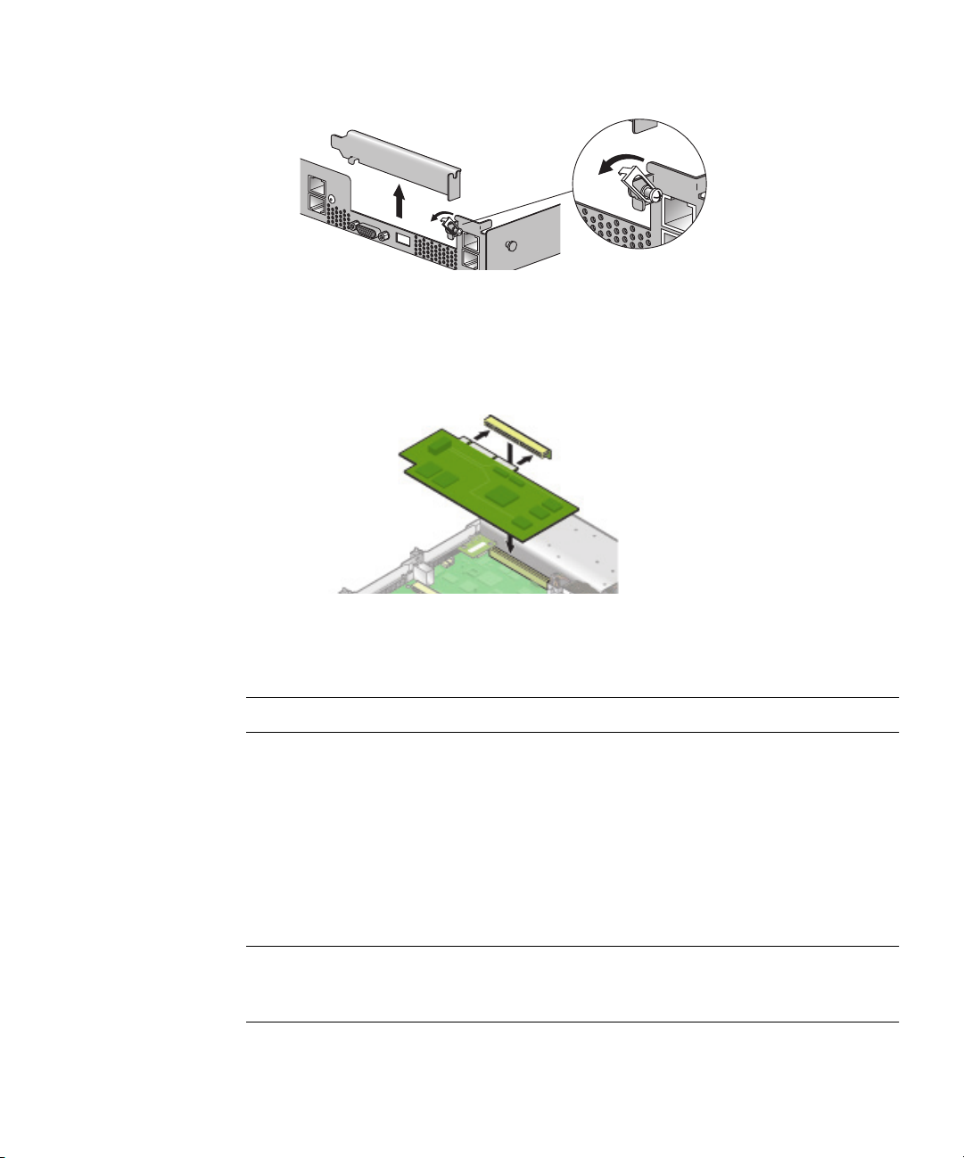
FIGURE 4-5 PCI Card Slot Cover
4. Remove the card riser assembly from the PCI card connector on the motherboard.
5. Install the PCI card in the riser assembly.
6. Reinstall the riser and card in the connector on the motherboard.
FIGURE 4-6 PCI Card and Riser
7. Pivot the card latch up and then slide it down until it captures the PCI card
bracket. Tighten the screw to secure the latch (refer to Figure 4-5).
Note – Check the routing of all cables for obstructions before reinstalling the cover.
4.4.2.2 To Remove an Existing PCI Card
1. Unfasten all cables connected to the card.
2. Withdraw the card and riser from the PCI card connector on the motherboard.
3. Remove the PCI card from the riser.
Installation is the reverse of this procedure.
Note – If the PCI card is being removed, but not replaced with another card:
Reinstall the empty riser assembly in the empty PCI card connector on the
motherboard. Reinstall the PCI card slot cover.
Chapter 4 Maintaining the Server 4-7
Page 60

4.4.3 SCSI Hard Disk Drive and Carrier
The following procedure describes how to remove and replace a SCSI hard disk
drive and carrier.
Note – SCSI hard disk drives are hot pluggable in integrated mirroring (IM)
configurations.
To withdraw the SCSI hard disk drive and carrier:
1. Squeeze the release latch and carefully swing the arm to the left as far as it
will go.
FIGURE 4-7 SCSI Hard Disk Drive Carrier and Latch Release
2. Grasp the carrier bezel with both hands and carefully pull the carrier out of the
drive bay.
Note – Avoid using the arm to remove the carrier.
To insert the SCSI hard disk drive and carrier:
1. Squeeze the release latch and carefully swing the arm to the left as far as it
will go
2. Grasping the body of the drive in both hands, carefully guide the connector end
of the SCSI carrier into the drive bay, sliding the carrier into the bay until the arm
engages and partially closes itself.
3. Push the arm forward and latch it to lock the carrier in place.
4-8 Sun Fire V20z Server User Guide • March 2004
Page 61

4.4.3.1 Replacing a Hard Disk Drive in a Carrier
1. Withdraw the carrier from the server as previously described.
2. Unfasten the four screws attached to the carrier and remove the backing plates.
3. Remove the new hard disk drive from its packaging.
4. Place the hard disk drive in the carrier and secure it with the four mounting
screws, as shown in Figure 4-8.
FIGURE 4-8 Installing a Hard Disk Drive in a Carrier
5. Re-insert the drive and carrier in the server as previously described.
Chapter 4 Maintaining the Server 4-9
Page 62

4.4.4 SCSI Backplane
The following procedure describes how to replace the SCSI backplane.
1. Turn off the system, including any attached peripherals.
2. While pressing the cover latch release button with your right thumb (A),
slide the
cover towards the rear of the chassis until it contacts the stop (B).
3. Lift the cover up and remove it.
A
B
FIGURE 4-9 Removing the Cover
4. Remove all hard disk drive carriers:
a. Squeeze the release latch and swing the arm to the left as far as it will go.
b. Grasp the carrier bezel with both hands and carefully pull the carrier out of the
drive bay.
Note – Avoid using the arm to remove the carrier.
FIGURE 4-10 SCSI Hard Disk Drive Carrier and Release Latch
4-10 Sun Fire V20z Server User Guide • March 2004
Page 63

5. Remove the center air baffle.
FIGURE 4-11 Removing the Center Air Baffle
6. Remove the second processor fan from the right:
a. Unplug the fan’s power connector from the motherboard.
b. Pull the fan straight up to remove it from the fan tray.
FIGURE 4-12 Removing a Cooling Fan
7. Remove the CPU VRM for CPU 1 (lefthand CPU) by pulling it straight up, out of
its sockets.
FIGURE 4-13 Removing the CPU 1 VRM
Chapter 4 Maintaining the Server 4-11
Page 64
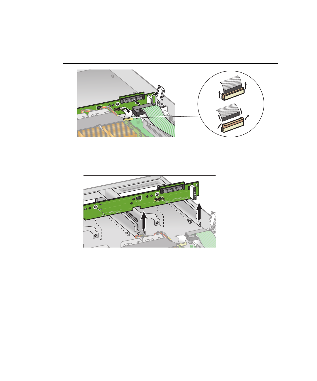
8. Disconnect the 5-pin power cable, the small flat cable, and the 68-pin ribbon
signal cable from the SCSI backplane.
Caution – Use care with the small flat cables. They are extremely fragile.
FIGURE 4-14 Uncabling the SCSI Backplane
9. Unfasten the two screws securing the backplane to the chassis.
10. Lift the SCSI backplane up and out of the chassis.
FIGURE 4-15 Removing the SCSI Backplane
4-12 Sun Fire V20z Server User Guide • March 2004
Page 65

Note – When reinstalling the SCSI backplane, ensure that the jumper is installed as
shown in Figure 4-16.
FIGURE 4-16 SCSI Backplane Jumper
Caution – Ensure that the fan wires are not pinched when reinstalling the
backplane.
Note – Check the routing of all cables for obstructions before reinstalling the cover.
Chapter 4 Maintaining the Server 4-13
Page 66
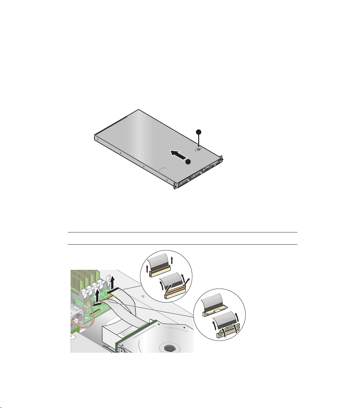
4.4.5 CD-ROM/DVD/Floppy Disk Drive Assembly
The following procedure describes how to replace the CD-ROM/DVD/Floppy Disk
Drive assembly.
1. Turn off the system, including any attached peripherals.
2. While pressing the cover latch release button with your right thumb (A),
slide the
cover towards the rear of the chassis until it contacts the stop (B).
3. Lift the cover up and remove it.
A
B
FIGURE 4-17 Removing the Cover
4. Unfasten the CD-ROM/DVD and Floppy disk drive ribbon cables from the
motherboard.
Caution – Use care with the small flat cables. They are extremely fragile.
FIGURE 4-18 Uncabling the CD-ROM/DVD/Floppy Disk Drive Assembly
4-14 Sun Fire V20z Server User Guide • March 2004
Page 67
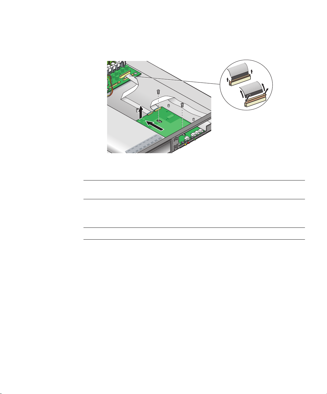
5. Unfasten the single screw securing the CD-ROM/DVD/Floppy Disk Drive
assembly to the chassis (see Figure 4-19).
6. Slide the assembly towards the rear of the chassis approximately 0.5” (12mm).
FIGURE 4-19 Removing the CD-ROM/DVD/Floppy Disk Drive Assembly
Caution – Move the assembly by grasping it by its sides. Do not to push on the
CD-ROM tray.
7. Lift the rear of the assembly slightly, and withdraw it from the chassis.
Installation is the reverse of this procedure.
Note – Check the routing of all cables for obstructions before reinstalling the cover.
Chapter 4 Maintaining the Server 4-15
Page 68
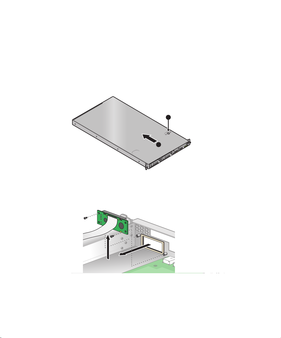
4.4.6 Operator Panel Board and Display
The following procedure describes how to replace the Operator Panel board and
LCD. The Operator Panel board is located beneath the CD-ROM/DVD/Floppy Disk
Drive assembly.
1. Turn off the system, including any attached peripherals.
2. While pressing the cover latch release button with your right thumb (A),
slide the
cover towards the rear of the chassis until it contacts the stop (B).
3. Lift the cover up and remove it.
A
B
FIGURE 4-20 Removing the Cover
4. Remove the CD-ROM/DVD/Floppy Disk Drive assembly (refer to the appropriate
procedure).
5. Remove the two screws securing the LCD to the front panel.
FIGURE 4-21 Removing the LCD
4-16 Sun Fire V20z Server User Guide • March 2004
Page 69
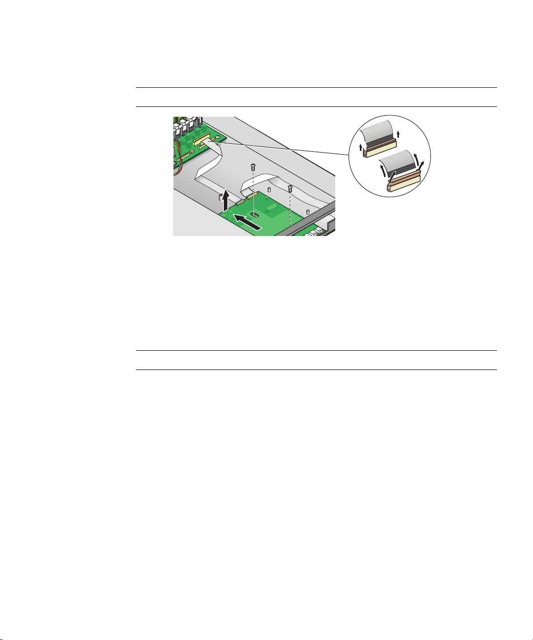
6. Unfasten the ribbon cable connecting the operator panel board to the
motherboard.
Caution – Use care with the small flat cables. They are extremely fragile.
FIGURE 4-22 Uncabling and Removing the Operator Panel Board
7. Remove the two screws and washers mounting the Operator Panel board to the
chassis.
8. Carefully slide the operator panel towards the rear of the chassis as far as
possible, to avoid damaging the switches. Raise the rear edge of the board first,
and then lift the Operator Panel board and LCD out of the chassis.
Installation is the reverse of this procedure.
Note – Check the routing of all cables for obstructions before reinstalling the cover.
Chapter 4 Maintaining the Server 4-17
Page 70
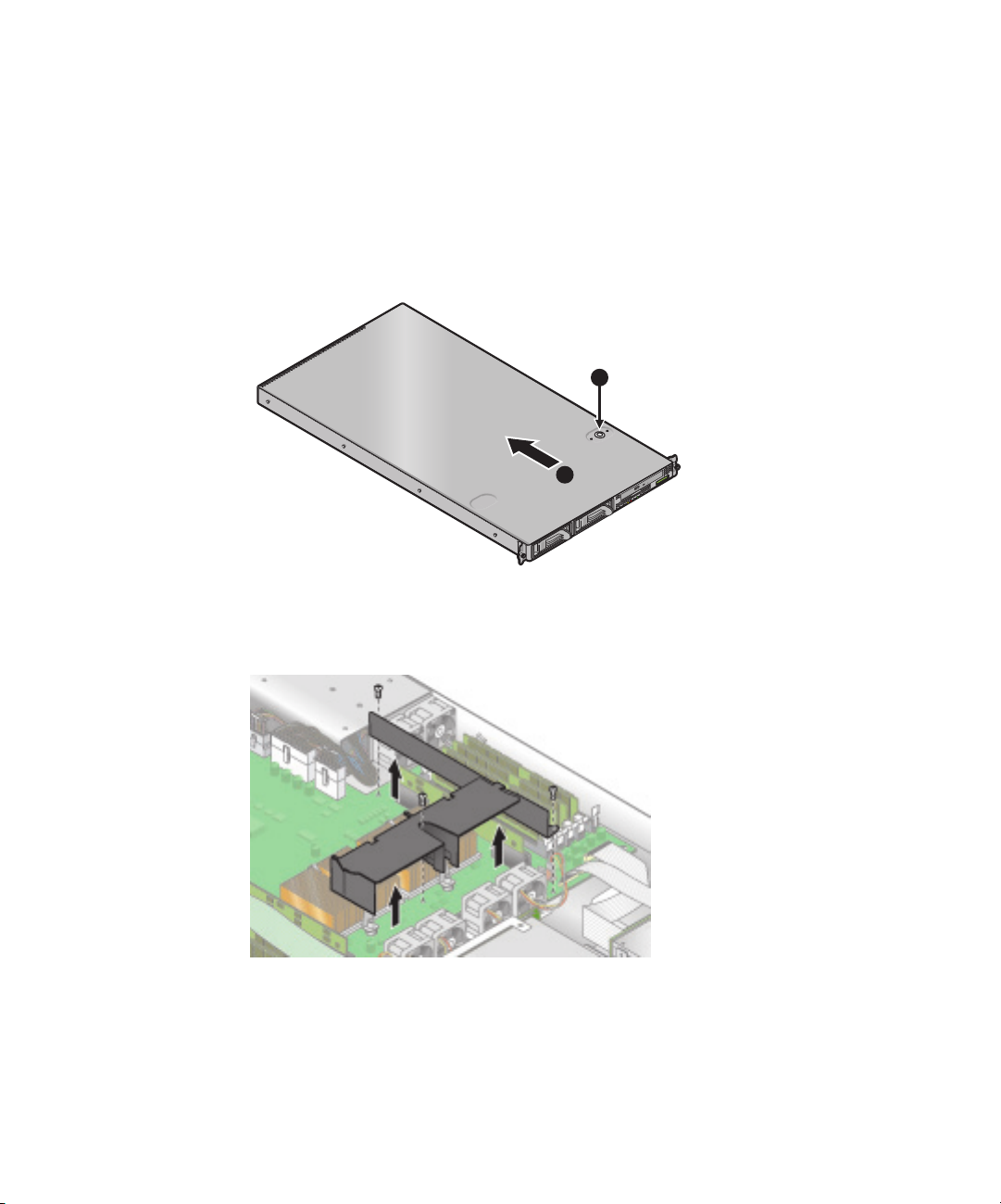
4.4.7 Power Supply
The following procedure describes how to replace the power supply.
1. Turn off the system, including any attached peripherals.
2. While pressing the cover latch release button with your right thumb (A),
slide the
cover towards the rear of the chassis until it contacts the stop (B).
3. Lift the cover up and remove it.
A
B
FIGURE 4-23 Removing the Cover
4. Unfasten the three screws securing the center and side air baffles. Lift the baffles
straight up to remove them
FIGURE 4-24 Removing the Center and Side Air Baffles
4-18 Sun Fire V20z Server User Guide • March 2004
Page 71
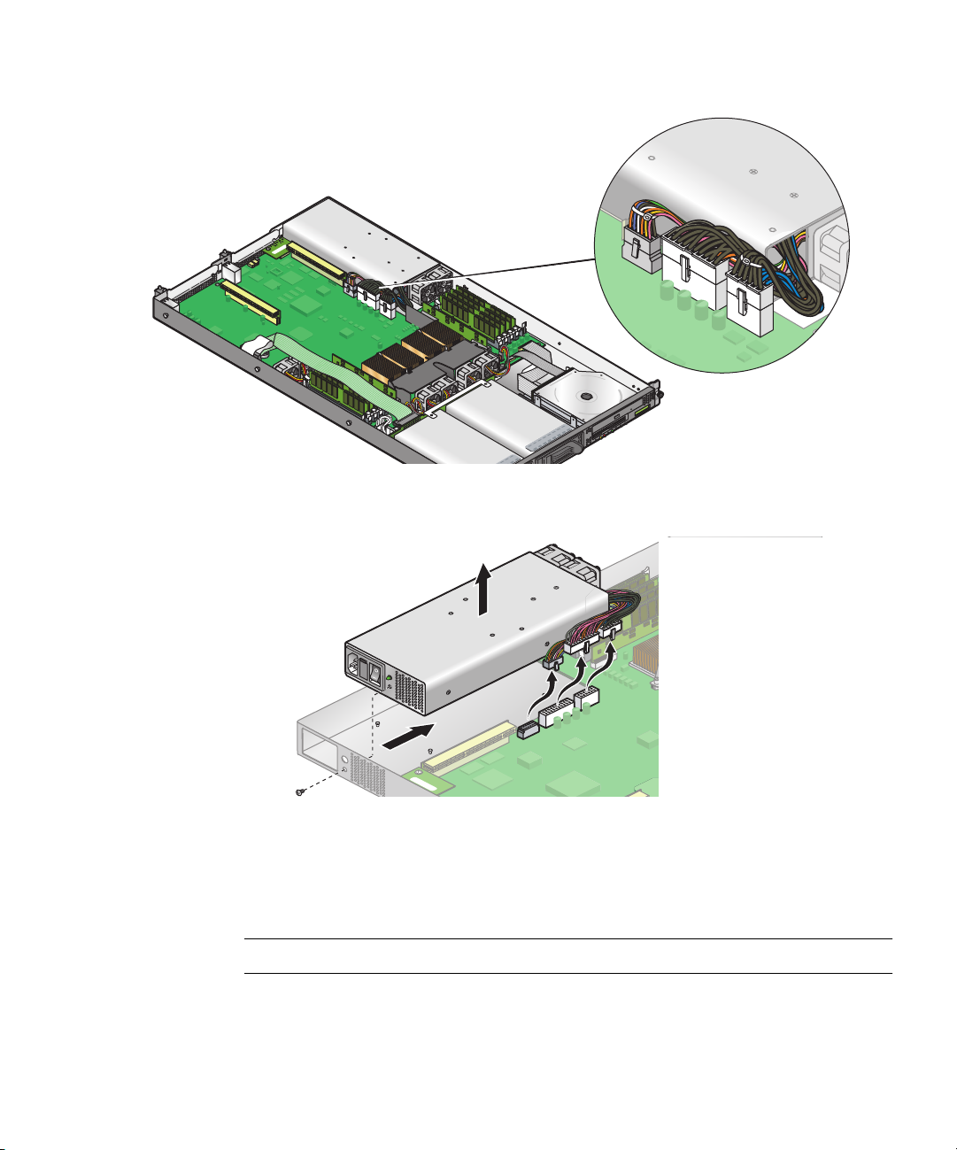
5. Disconnect the three power supply cables from the motherboard.
FIGURE 4-25 Disconnecting the Power Supply Cables
6. Unfasten the single screw securing the power supply to the rear of the chassis.
FIGURE 4-26 Removing the Power Supply
7. Slide the power supply toward the front of the chassis, and lift it out of the
chassis.
Installation is the reverse of this procedure.
Note – Check the routing of all cables for obstructions before reinstalling the cover.
Chapter 4 Maintaining the Server 4-19
Page 72
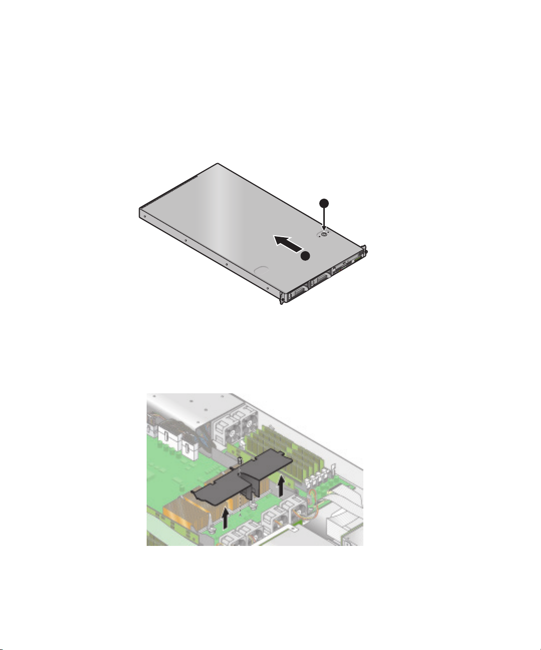
4.4.8 Cooling Fans
The following procedure describes how to replace a cooling fan.
1. Press the power switch, on the Operator Panel, to turn off the power to the server.
2. While pressing the cover latch release button with your right thumb (A),
slide the
cover towards the rear of the chassis until it contacts the stop (B).
3. Lift the cover up and remove it.
A
B
FIGURE 4-27 Removing the Cover
4. Identify the fan(s) to be replaced.
5. If you are replacing a processor cooling fan, unfasten the single screw securing
the center air baffle and lift the baffle away from the chassis. Otherwise, continue
to Step 6.
FIGURE 4-28 Removing the Center Air Baffle
4-20 Sun Fire V20z Server User Guide • March 2004
Page 73

6. Unplug the fan’s power connector from the motherboard.
FIGURE 4-29 Removing the Cooling Fans
7. Pull the fan straight up to remove it from the fan tray.
Installation is the reverse of this procedure.
Caution – Ensure that the fan airflow direction is correct (front to rear) by installing
the fan so that the airflow direction arrow points towards the rear of the chassis.
After installing a new fan, allow sufficient time for the system to recognize the fan
and determine whether it is functioning properly.
Note – Check the routing of all cables for obstructions before reinstalling the cover.
Chapter 4 Maintaining the Server 4-21
Page 74

4.4.9 Memory Voltage Regulator Modules
The following procedure describes how to replace a memory voltage regulator
module (VRM).
1. Turn off the system, including any attached peripherals.
2. While pressing the cover latch release button with your right thumb (A),
slide the
cover towards the rear of the chassis until it contacts the stop (B).
3. Lift the cover up and remove it.
A
B
FIGURE 4-30 Removing the Cover
4. Identify the memory VRM that needs to be replaced.
5. Remove a memory VRM by pressing down on the ejector bars at both ends of the
socket.
FIGURE 4-31 Removing a Memory VRM
Installation is the reverse of this procedure.
Note – Check the routing of all cables for obstructions before reinstalling the cover.
4-22 Sun Fire V20z Server User Guide • March 2004
Page 75
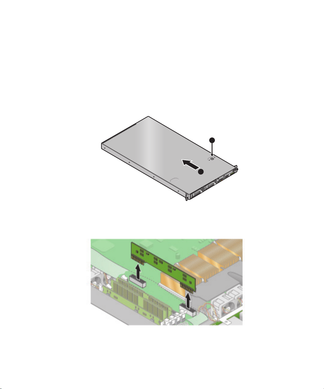
4.4.10 CPU Voltage Regulator Modules
The following procedure describes how to remove and replace a CPU voltage
regulator module (VRM).
To remove a CPU VRM:
1. Turn off the system, including any attached peripherals.
2. While pressing the cover latch release button with your right thumb (A),
cover towards the rear of the chassis until it contacts the stop (B).
3. Lift the cover up and remove it.
A
B
FIGURE 4-32 Removing the Cover
4. Identify the CPU VRM that needs to be replaced.
5. Remove the CPU VRM by pulling it straight up, out of its socket.
slide the
FIGURE 4-33 Removing a CPU VRM
Chapter 4 Maintaining the Server 4-23
Page 76

To replace a CPU VRM:
1. Press the new VRM into the empty socket until it snaps into place, ensuring that
the notch in the CPU VRM aligns with the key in the connector.
2. When installing a VRM, ensure that pin “A1”, on the VRM, is aligned with the
“A1” reference designation on the motherboard.
3. Check the routing of all cables for obstructions and then reinstall the cover.
4-24 Sun Fire V20z Server User Guide • March 2004
Page 77

4.4.11 Memory Modules
The following procedure describes how to remove and replace memory modules.
To remove a memory module:
1. Turn off the system, including any attached peripherals.
2. While pressing the cover latch release button with your right thumb (A),
slide the
cover towards the rear of the chassis until it contacts the stop (B).
3. Lift the cover up and remove it.
A
B
FIGURE 4-34 Removing the Cover
4. Locate the memory module connector in which you will install or replace a
memory module.
5. Remove a memory module by pressing down on the ejector bars at both ends of
the memory module’s socket.
FIGURE 4-35 Removing a Memory Module
Chapter 4 Maintaining the Server 4-25
Page 78

To install a memory module:
1. Ensure that the memory module socket’s ejectors are open (rotated outward) to
allow the new module to be inserted.
2. Align the memory module’s edge connector with the alignment key, and insert the
memory module into the connector.
Note – The manufacturer and capacity of both modules in the same memory bank
(Banks 1-4) must be identical.
3. Check the routing of all cables for obstructions and then reinstall the cover.
4-26 Sun Fire V20z Server User Guide • March 2004
Page 79

4.4.12 System Battery
The system battery is a 3.0-volt standard 20 mm Lithium coin-cell battery.
You may need to replace the system battery if you know it is weak or if after any
period of AC power loss, the BIOS loses its’ CMOS settings or if the time-of-day
clock loses time.
Caution – Do not attempt to open or service batteries. The battery contains lithium
and can explode if not properly used, handled, or disposed of.
To remove the system battery:
1. Turn off the system, including any attached peripherals.
2. While pressing the cover latch release button with your right thumb (A),
cover towards the rear of the chassis until it contacts the stop (B).
3. Lift the cover up and remove it.
A
B
FIGURE 4-36 Removing the Cover
slide the
Chapter 4 Maintaining the Server 4-27
Page 80
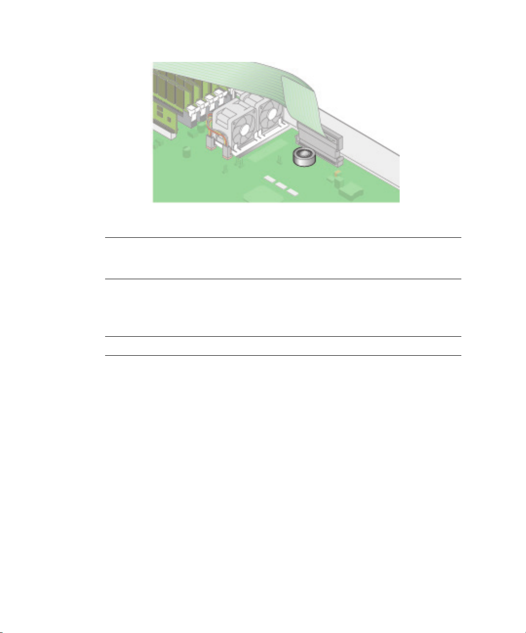
4. Remove the system battery by sliding it back and prying it from the holder.
FIGURE 4-37 Removing the System Battery
Caution – Do not dispose of the battery with regular waste. Discard used batteries
according to the manufacturer’s instructions or contact your local waste disposal
agency for the location of the nearest battery deposit site.
To replace the system battery:
1. Install the new system battery into the holder with the side labeled "+" facing up.
Note – Replace the battery only with the identical model.
2. Check the routing of all cables for obstructions and then reinstall the cover.
4-28 Sun Fire V20z Server User Guide • March 2004
Page 81
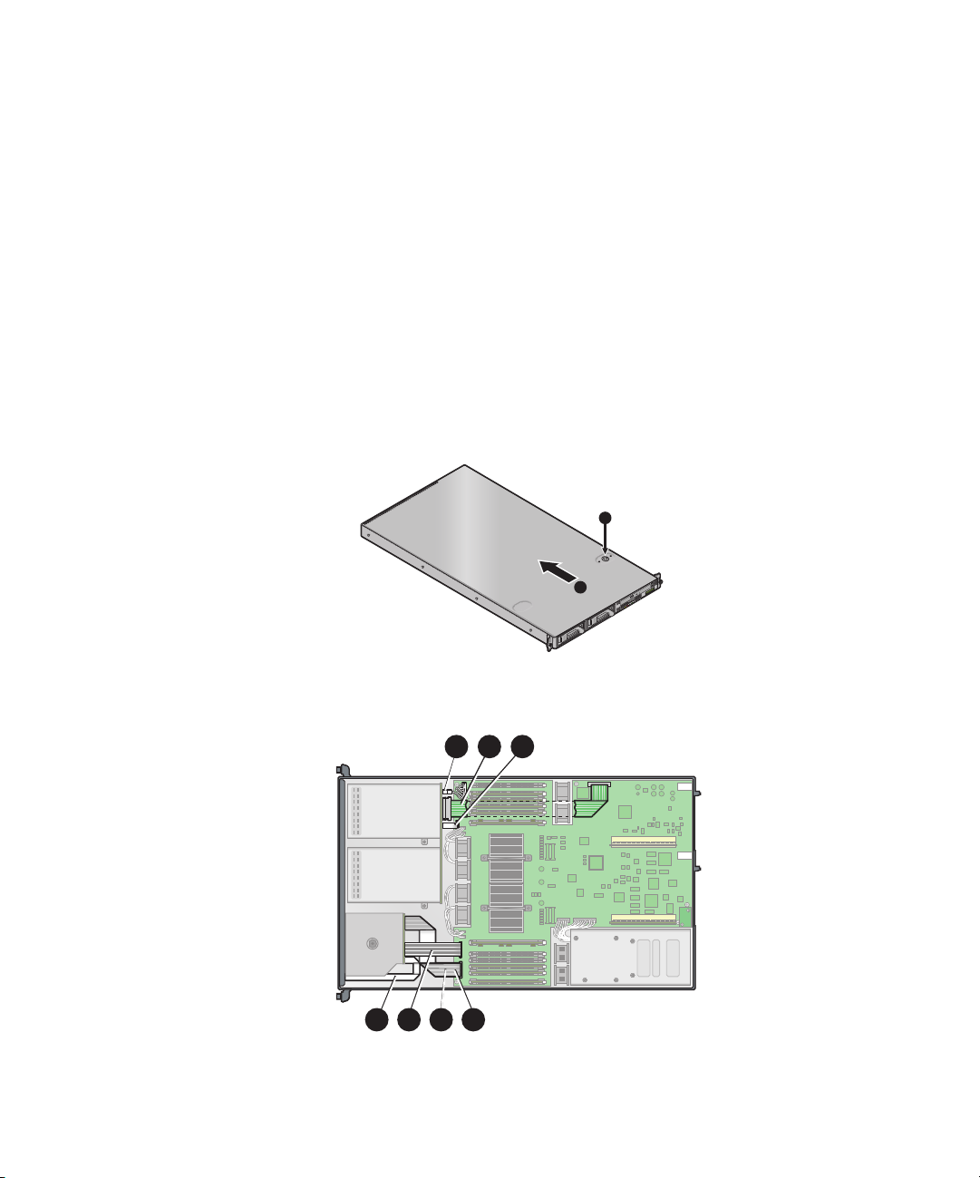
4.4.13 Cable Kit
The following procedure describes how to remove and replace the following cables:
1. Five-pin cable connecting the SCSI backplane to the motherboard.
2. 68-pin ribbon cable connecting the SCSI backplane to the motherboard.
3. Flat cable connecting the SCSI backplane to the motherboard.
4. Flat cable connecting the operator panel board to the LCD.
5. Flat cable connecting the CD-ROM/DVD to the motherboard.
6. Flat cable connecting the Floppy Disk Drive to the motherboard.
7. Flat cable connecting the operator panel board to the motherboard.
1. Turn off the system, including any attached peripherals.
2. While pressing the cover latch release button with your right thumb (A),
cover towards the rear of the chassis until it contacts the stop (B).
3. Lift the cover up and remove it.
A
B
FIGURE 4-38 Removing the Cover
4. Identify the cable to be replaced.
1 32
slide the
4 5 6 7
FIGURE 4-39 V20z System Cables
Chapter 4 Maintaining the Server 4-29
Page 82

The two halves of the 5-pin SCSI backplane power cable connector (1) are secured
with a hook.
The 68-pin SCSI ribbon cable (2) has no locking mechanism.
The small flat cables (3-7) are attached using two different types of zero insertion
force (ZIF) cable connectors. Because of their small size, it may be difficult to
distinguish one connector type from the other.
Refer to Figure 4-40 for the methods used to release cables from the various types of
connector.
Caution – Use caution when removing cables as they are fragile—the small flat
flexible cables and cable connectors are extremely sensitive.
FIGURE 4-40 Cable Connectors
Note – Check the routing of all cables for obstructions before reinstalling the cover.
4-30 Sun Fire V20z Server User Guide • March 2004
Page 83
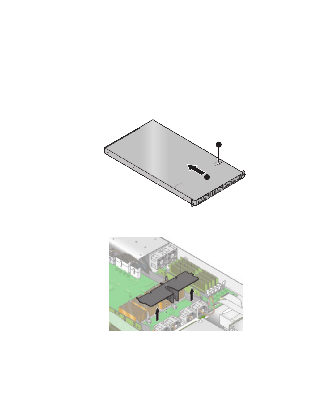
4.4.14 CPUs
The following procedure describes how to replace a CPU.
4.4.14.1 Removing a Heatsink and CPU
1. Turn off the system, including any attached peripherals.
2. While pressing the cover latch release button with your right thumb (A),
cover towards the rear of the chassis until it contacts the stop (B).
3. Lift the cover up and remove it.
A
B
FIGURE 4-41 Removing the Cover
4. Unfasten the single securing and remove the center air baffle.
slide the
FIGURE 4-42 Removing the Center Air Baffle
Chapter 4 Maintaining the Server 4-31
Page 84
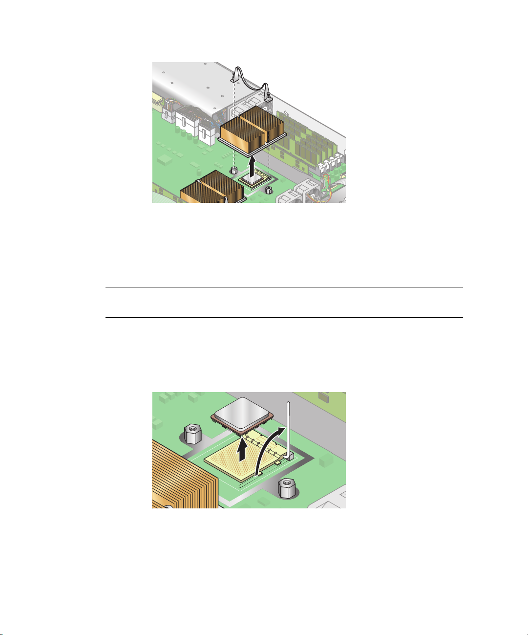
5. Unfasten the two securing screws and remove the heatsink securing clip.
FIGURE 4-43 Removing the Securing Clip and Heatsink
6. Twist the heatsink slightly to the right or left, in order to break the seal with the
thermal grease.
7. Lift the heatsink away from the CPU.
Note – The heatsink can become extremely hot. Be sure it has had sufficient time to
cool before handling.
8. Place the heatsink upside down on a flat surface to prevent the thermal grease
from contaminating other components.
9. Pull the socket release lever up to the fully open, perpendicular position.
10. Lift the CPU out of the socket, leaving the release lever in the open position.
FIGURE 4-44 Removing a CPU from its Socket
4-32 Sun Fire V20z Server User Guide • March 2004
Page 85

4.4.14.2 Installing a CPU and Heatsink
1. Unpack the new CPU.
Caution – Observe the appropriate ESD precautions.
2. Ensure that the socket release lever is in the fully open, perpendicular position.
3. Align the small triangle, on the corner of the CPU, with the triangle on the corner
of the socket.
FIGURE 4-45 Installing a CPU in its Socket
4. Insert the CPU into the socket.
Note – If correctly aligned, the CPU should easily insert into the socket. If more
than minimal resistance is felt, stop and recheck the alignment. Forcing a misaligned
CPU into the socket will permanently damage the device.
5. When the CPU is fully seated in the socket, rotate the socket release lever until it
snaps into place, securing the CPU in the socket.
6. Use the syringe to apply approximately 0.1 ML/CC of thermal grease in a circular
pattern to the top of the CPU.
7. Gently distribute the thermal grease and remove any excess so that only an
extremely thin, uniform layer remains. If any voids or crevices appear that could
lead to air pockets, reapply the grease until you achieve a thin but compact
consistency.
8. Use an alcohol pad to remove all thermal grease from the bottom of the heatsink.
9. Inspect the heatsink for dust and lint. Clean if necessary.
Chapter 4 Maintaining the Server 4-33
Page 86

10. Ensure the foam strip under the heatsink area is intact and has not been removed,
loosened, or damaged. This foam strip is critical to proper air flow.
11. Carefully position the heatsink on the CPU, aligning it with the mounting posts to
reduce movement after it makes initial contact with the layer of thermal grease.
Caution – If the heatsink is moved too much during its installation, the layer of
thermal grease may become uneven, leading to component damage.
12. After the heatsink is correctly aligned, reinstall the heatsink clips so that the
longer tab points toward the fans.
13. Tighten the clip securing screws.
14. Replace the center air duct and the system cover.
Note – Check the routing of all cables for obstructions before reinstalling the cover.
4-34 Sun Fire V20z Server User Guide • March 2004
Page 87

4.4.15 Super CRU
The Super CRU is a chassis containing all of the system components, except those
designated as customer replaceable. To install a Super CRU, you must remove all of
the CRUs from the system to be replaced. Then, reinstall all of those components in
the Super CRU chassis.
Note – The only customer-replaceable unit that is included in the Super CRU is the
Operator Panel board and LCD assembly.
1. Turn off the system, including any attached peripherals.
2. While pressing the cover latch release button with your right thumb (A),
slide the
cover towards the rear of the chassis until it contacts the stop (B).
3. Lift the cover up and remove it.
A
B
FIGURE 4-46 Removing the Cover
Remove the following components and reinstall them in the Super CRU chassis.
(Refer to the appropriate instructions to remove and replace each component):
■ I/O Board
■ PCI Card(s) and Risers (2)
■ Hard Disk Drive (1-2) and Carrier (2)
■ SCSI Backplane
■ CD-ROM/DVD/Floppy Disk Drive Assembly
■ Power Supply
■ Cooling Fans (6)
■ Memory VRMs (1-2)
■ CPU VRMs (1-2)
Chapter 4 Maintaining the Server 4-35
Page 88

■ Memory Modules (1-8)
■ CPUs and Heatsinks (1-2)
Note – You must remove the center air baffle (with the part number label) from the
system being repaired and install it in the Super CRU. The part number label
contains important information about the components in your particular system.
Powe r
Supply
I/O
Board
PCI Riser
(full length)
0
VRMs/DIMMs
CPUs and Heatsinks (2)
Center
Air Baffle
PCI Riser
(half length)
Fans (2)
VRMs/DIMMs
Fans (4)
FIGURE 4-47 Component Locations
SCSI
Backplane
1
1
HD bays (2)
2
CD/DVD-FD
Drive Module
SCSI HDDs
with Carriers
4-36 Sun Fire V20z Server User Guide • March 2004
Page 89

APPENDIX
A
System Specifications
To obtain maximum reliability and performance, install your Sun Fire V20z server
into a proper environment and ensure correct configuration as discussed in this
chapter.
A.1 Physical Specifications
TABLE A-1 Sun Fire V20z Server Physical Specifications
Specification English Metric
Width 16.94 in. 430.276 mm
Depth
Height
Weight (max.) 35 lbs 15.88 kg
28 in. 711.2 mm
1.69 in. 42.93 mm
A-1
Page 90

A.2 Power Specifications
TABLE A-2 Sun Fire V20z Server AC Input Specifications
Specification Value
Universal AC Input 100 to 240 VAC, 50/60 Hz
Maximum current 7.0 amps
A.3 Environmental Specifications
TABLE A-3 Sun Fire V20z Server Unit Level Environmental Specifications
Specification State English Metric
Temperature Operating 50 to 95 degrees F 10 to 35 degrees C
Non-operating -40 to 149 degrees F -40 to 65 degrees C
Humidity Operating 10% to 90% RH at 80. 6
degrees F max. wet bulb
(non-condensing)
Non-operating 10% to 90% RH 10% to 90% RH
Altitude Operating Up to 9,800 feet Up to 3,000 meters
Non-operating Up to 39,370 feet Up to 12,000 meters
Vibration Operating .20 G, 5 to 500 Hz sine
sweep
Shock Operating 5 G, 11 ms half-sine
* The temperature specifications in this table are rated for sea level. For each rise of 300 meters in altitude, the
maximum temperature drops by 1 degree C.
10% to 90% RH at 27
degrees C max. wet bulb
(non-condensing)
*
A-2 Sun Fire V20z Server User Guide • March 2004
Page 91

APPENDIX
B
BIOS POST Codes
Typically, the BIOS displays warning or error messages on the video display in the
event of hardware or configuration errors. However, in some cases the error may be
so severe that the BIOS halts immediately, or BIOS might be unable to initialize
video. In these cases, it can be useful to determine the last Power On Self Test
(POST) task that the BIOS was executing. This is indicated by the value written to
port 80.
For information about retrieving the last port 80 post code using the sp get
port80 command, refer to the Sun Fire V20z Server Management Guide,
for details.
You can also retrieve the last 10 port 80 post codes using the operator panel. Refer to
the Sun Fire V20z Server Management Guide,
817-5249-xx, for more details about using
the operator panel menus.
817-5249-xx,
TABLE B-1 lists the POST codes for the Sun Fire V20z BIOS.
TABLE B-1 BIOS POST Codes
Post Code Description
02 Verify real mode
03 Disable non-maskable interrupt (NMI)
04 Get CPU type
06 Initialize system hardware
07 Disable shadow and execute code from the ROM
08 Initialize chipset with initial POST values
09 Set IN POST fl ag
0A Initialize CPU registers
0B Enable CPU cache
0C Initialize caches to initial POST values
B-1
Page 92

TABLE B-1 BIOS POST Codes (Continued)
Post Code Description
0E Initialize I/O component
0F Initialize the local bus IDE
10 Initialize power management
11 Load alternate registers with initial POST values
12 Restore CPU control word during warm boot
13 Initialize PCI bus mastering devices
14 Initialize keyboard controller
16 BIOS ROM checksum
17 Initialize cache before memory autosize
18 8254 programmable interrupt timer initialization
1A 8237 DMA controller initialization
1C Reset programmable interrupt controller
20 Test DRAM refresh
22 Test 8742 keyboard controller
24 Set ES segment register to 4GB
26 Enable gate A20 line
28 Autosize DRAM
29 Initialize POST memory manager
2A Clear 512KB base RAM
2C RAM failure on address line xxxx
2E RAM failure on data bits xxxx of low byte of memory bus
2F Enable cache before system BIOS shadow
30 RAM failure on data bits xxxx of high byte of memory
bus
32 Test CPU bus clock frequency
33 Initialize Phoenix Dispatch Manager
36 Warm start shut down
38 Shadow system BIOS ROM
3A Autosize cache
3C Advanced configuration of chipset registers
3D Load alternate registers with CMOS values
B-2 Sun Fire V20z Server User Guide • March 2004
Page 93

TABLE B-1 BIOS POST Codes (Continued)
Post Code Description
41 Initialize extended memory for RomPilot
42 Initialize interrupt vectors
45 POST device initialization
46 Check ROM copyright notice
47 Initialize I20 support
48 Check video configuration against CMOS
49 Initialize PCI bus and devices
4A Initialize all video adapters in system
4B QuietBoot start (optional)
4C Shadow video BIOS ROM
4E Display BIOS copyright notice
4F Initialize MultiBoot
50 Display CPU type and speed
51 Initialize EISA board
52 Test keyboard
54 Set key click if enabled
55 Enable USB devices
58 Test for unexpected interrupts
59 Initialize POST display service
5A Display prompt "Press F2 to enter SETUP"
5B Disable CPU cache
5C Test RAM between 512KB and 640KB
60 Test extended memory
62 Test extended memory address lines
64 Jump to UserPatch1
66 Configure advanced cache registers
67 Initialize Multi Processor APIC
68 Enable external and CPU caches
69 Setup system management mode (SMM) area
6A Display external L2 cache size
Appendix B BIOS POST Codes B-3
Page 94

TABLE B-1 BIOS POST Codes (Continued)
Post Code Description
6B Load custom defaults (optional)
6C Display shadow area message
6E Display possible high address for UMB recovery
70 Display error messages
72 Check for confi guration errors
76 Check for keyboard errors
7C Set up hardware interrupt vectors
7D Initialize Intelligent System Monitoring
7E Initialize coprocessor if present
80 Disable onboard super I/O ports and IRQ's
81 Late POST device initialization
82 Detect and install external RS232 ports
83 Configure non-MCD IDE controllers
84 Detect and install external parallel ports
85 Initialize PC compatible PnP ISA devices
86 Reinitialize onboard I/O ports
87 Configure motherboard configurable devices (optional)
88 Initialize BIOS data area
89 Enable non-maskable interrupts (NMIs)
8A Initialize extended BIOS data area
8B Test and initialize PS/2 mouse
8C Initialize floppy controller
8F Determine number of ATA drives (optional)
90 Initialize hard disk controllers
91 Initialize local bus hard disk controllers
92 Jump to UserPatch2
93 Build MPTABLE for multi processor boards
95 Install CD ROM for boot
96 Clear huge ES segment register
97 Fixup multi processor table
B-4 Sun Fire V20z Server User Guide • March 2004
Page 95

TABLE B-1 BIOS POST Codes (Continued)
Post Code Description
98 Search for option ROMs
99 Check for SMART drive (optional)
9A Shadow option ROMs
9C Set up power management
9D Initialize security engine (optional)
9E Enable hardware interrupts
9F Determine number of ATA and SCSI drives
A0 Set time of day
A2 Check key lock
A4 Initialize typematic rate
A8 Erase F2 prompt
AA Scan for F2 key stroke
AC Enter setup
AE Clear boot flag
B0 Check for errors
B1 Inform RomPilot about the end of POST
B2 POST done - prepare to boot operating system
B4 One short beep
B5 Terminate QuietBoot (optional)
B6 Check password
B7 Initialize ACPI BIOS
B9 Prepare boot
BA Initialize DMI parameters
BB Initialize PnP option ROMs
BC Clear parity checkers
BD Display multiboot menu
BE Clear screen
BF Check virus and backup reminders
C0 Try to boot with interrupt 19
C1 Initialize POST Error Manager (PEM)
Appendix B BIOS POST Codes B-5
Page 96

TABLE B-1 BIOS POST Codes (Continued)
Post Code Description
C2 Initialize error logging
C3 Initialize error display function
C4 Initialize system error handler
C5 PnP dual CMOS (optional)
C6 Initialize notebook docking (optional)
C7 Initialize notebook docking late
C8 Force check (optional)
C9 Extended checksum (optional)
CA Redirect Int 15h to enable remote keyboard
CB Redirect Int 13 to Memory Technologies Devices such as
ROM, RAM, PCMCIA, and serial disk
CC Redirect Int 10h to enable remote serial video
CD Re-map I/O and memory for PCMCIA
CE Initialize digitizer and display message
D2 Unknown interrupt
TABLE B-2 shows the POST codes for the boot block in Flash ROM.
TABLE B-2 Boot Block in Flash ROM
Post Code Description
E0 Initialize the chipset
E1 Initialize the bridge
E2 Initialize the CPU
E3 Initialize the system timer
E4 Initialize system I/O
E5 Check force recovery boot
E6 Checksum BIOS ROM
E7 Go to BIOS
E8 Set Huge Segment
E9 Initialize Multi Processor
EA Initialize OEM special code
EB Initialize PIC and DMA
B-6 Sun Fire V20z Server User Guide • March 2004
Page 97

TABLE B-2 Boot Block in Flash ROM (Continued)
Post Code Description
EC Initialize Memory type
ED Initialize Memory size
EE Shadow Boot Block
EF System memory test
F0 Initialize interrupt vectors
F1 Initialize Run Time Clock
F2 Initialize video
F3 Initialize System Management Manager
F4 Output one beep
F5 Clear Huge Segment
F6 Boot to mini DOS
F7 Boot to Full DOS
Appendix B BIOS POST Codes B-7
Page 98

B-8 Sun Fire V20z Server User Guide • March 2004
Page 99

APPENDIX
C
Diagnostics Commands
You can use the diags subcommands shown in TABLE C-1 to manage diagnostics
tests:
TABLE C-1 Diagnostic Subcommands
Subcommand Description
diags cancel tests Cancels one or more diagnostic tests, resulting in
the deletion of the results data.
diags get state Returns the state of the platform diagnostics
control server.
diags get tests Returns data describing the diagnostic tests that
are available and their requirements and
parameters.
diags run tests Submits one or more diagnostic tests for execution.
diags start Starts the Service Processor and platform
diagnostics framework.
diags terminate Terminates all diagnostics tests and terminates the
diagnostics subsystem.
Note – Every command returns a return code upon completion.
C-1
Page 100

C.1 diags cancel tests
C.1.1 Command
Access: Administrators
Description: Cancels one or more diagnostic tests, resulting in the deletion of results
data.
Command format: diags cancel tests [[{ -t | --test} test_handle] [{-
a|--all}] [{-H | --noheader}]]
Arguments Description
{ -t | --test} Specifies the test to cancel. (Note: The test_handle is
the same as the test handle that is output to the
screen when you submit the test.)
{-a | --all} Cancels all tests.
{-H | --noheader} Suppresses header output.
Specifying no arguments cancels all tests for each device in the system.
C.1.2 Return Codes
Following are the return values for this command:
Return Code ID Description
NWSE_Success 0 Command successfully completed.
NWSE_InvalidUsage 1 Invalid usage: bad parameter usage,
NWSE_RPCTimeout 2 Request was issued, but was not serviced
C-2 Sun Fire V20z Server User Guide • March 2004
conflicting options specified.
by the server. RPC procedure timed out
and the request may or may not have
been serviced by the server.
 Loading...