


Artisan Technology Group is your source for quality
new and certied-used/pre-owned equipment
• FAST SHIPPING AND
DELIVERY
• TENS OF THOUSANDS OF
IN-STOCK ITEMS
• EQUIPMENT DEMOS
• HUNDREDS OF
MANUFACTURERS
SUPPORTED
• LEASING/MONTHLY
RENTALS
• ITAR CERTIFIED
SECURE ASSET SOLUTIONS
SERVICE CENTER REPAIRS
Experienced engineers and technicians on staff
at our full-service, in-house repair center
Instra
Remotely inspect equipment before purchasing with
our interactive website at www.instraview.com
Contact us: (888) 88-SOURCE | sales@artisantg.com | www.artisantg.com
SM
REMOTE INSPECTION
View
WE BUY USED EQUIPMENT
Sell your excess, underutilized, and idle used equipment
We also offer credit for buy-backs and trade-ins
www.artisantg.com/WeBuyEquipment
LOOKING FOR MORE INFORMATION?
Visit us on the web at www.artisantg.com for more
information on price quotations, drivers, technical
specications, manuals, and documentation

UltraSPARC User’s Manual
UltraSP ARC-I
UltraSP ARC-II
July 1997
Sun Microelectronics
901 San Antonio Road
Palo Alto, CA 94303
Part No: 802-7220-02
This July 1997 -02 Revision is only available on-
line. The only changes made were to support
hypertext links in the pdf file.
Artisan Technology Group - Quality Instrumentation ... Guaranteed | (888) 88-SOURCE | www.artisantg.com

Copyright © 1997 Sun Microsystems, Inc. All Rights Reserved.
THE INFORMATION CONTAINED IN THIS DOCUMENT IS PROVIDED “AS
IS” WITHOUT ANY EXPRESS REPRESENTATIONS OR WARRANTIES. IN
ADDITION, SUN MICROSYSTEMS, INC. DISCLAIMS ALL IMPLIED
REPRESENTATIONS AND WARRANTIES, INCLUDING ANY WARRANTY OF
MERCHANTABILITY, FITNESS FOR A PARTICULAR PURPOSE, OR NONINFRINGEMENT OF THIRD PARTY INTELLECTUAL PROPERTY RIGHTS.
This document contains proprietary information of Sun Microsystems, Inc. or
under license from third parties. No part of this document may be reproduced in
any form or by any means or transferred to any third party without the prior
written consent of Sun Microsystems, Inc.
Sun, Sun Microsystems, and the Sun logo are trademarks or registered
trademarks of Sun Microsystems, Inc. in the United States and other countries.
All SPARC trademarks are used under license and are trademarks or registered
trademarks of SPARC International, Inc. in the United States and other countries.
Products bearing SPARC trademarks are based upon an architecture developed
by Sun Microsystems, Inc.
The information contained in this document is not designed or intended for use
in on-line control of aircraft, air traffic, aircraft navigation or aircraft
communications; or in the design, construction, operation or maintenance of any
nuclear facility. Sun disclaims any express or implied warranty of fitness for such
uses.
Printed in the United States of America.
Artisan Technology Group - Quality Instrumentation ... Guaranteed | (888) 88-SOURCE | www.artisantg.com

Contents
Preface ..................................................................................................................................... 9
Overview ...................................................................................................................... 9
A Brief History of SPARC.......................................................................................... 9
How to Use This Book................................................................................................ 10
Section I — Introducing UltraSPARC
1. UltraSPARC Basics................................................................................................................ 3
1.1 Overview ...................................................................................................................... 3
1.2 Design Philosophy ...................................................................................................... 3
1.3 Component Overview ................................................................................................ 5
1.4 UltraSPARC Subsystem.............................................................................................. 10
2. Processor Pipeline................................................................................................................. 11
2.1 Introductions................................................................................................................11
2.2 Pipeline Stages............................................................................................................. 12
3. Cache Organization .............................................................................................................. 17
3.1 Introduction.................................................................................................................. 17
4. Overview of the MMU......................................................................................................... 21
4.1 Introduction.................................................................................................................. 21
4.2 Virtual Address Translation ...................................................................................... 21
Section II — Going Deeper
5. Cache and Memory Interactions ........................................................................................ 27
Artisan Technology Group - Quality Instrumentation ... Guaranteed | (888) 88-SOURCE | www.artisantg.com

5.2 Cache Flushing............................................................................................................. 27
5.3 Memory Accesses and Cacheability ......................................................................... 29
5.4 Load Buffer................................................................................................................... 39
5.5 Store Buffer................................................................................................................... 40
6.1 Introduction.................................................................................................................. 41
6.2 Translation Table Entry (TTE) ................................................................................... 41
6.3 Translation Storage Buffer (TSB)............................................................................... 44
6.4 MMU-Related Faults and Traps................................................................................ 47
6.5 MMU Operation Summary........................................................................................ 50
6.6 ASI Value, Context, and Endianness Selection for Translation............................ 52
6.7 MMU Behavior During Reset, MMU Disable, and RED_state............................. 54
6.8 Compliance with the SPARC-V9 Annex F............................................................... 55
6.9 MMU Internal Registers and ASI Operations ......................................................... 55
6.10 MMU Bypass Mode..................................................................................................... 68
6.11 TLB Hardware.............................................................................................................. 69
7.1 Introduction.................................................................................................................. 73
7.2 Overview of UltraSPARC External Interfaces......................................................... 73
7.3 Interaction Between E-Cache and UDB.................................................................... 76
7.4 SYSADDR Bus Arbitration Protocol......................................................................... 84
7.5 UltraSPARC Interconnect Transaction Overview .................................................. 92
7.6 Cache Coherence Protocol.......................................................................................... 94
7.7 Cache Coherent Transactions .................................................................................... 102
7.8 Non-Cached Data Transactions................................................................................. 109
7.9 S_RTO/S_ERR ............................................................................................................. 111
7.10 S_REQ............................................................................................................................ 111
7.11 Writeback Issues.......................................................................................................... 112
7.12 Interrupts (P_INT_REQ)............................................................................................. 116
7.13 P_REPLY and S_REPLY.............................................................................................. 117
7.14 Multiple Outstanding Transactions.......................................................................... 126
7.15 Transaction Set Summary........................................................................................... 129
7.16 Transaction Sequences................................................................................................ 131
7.17 Interconnect Packet Formats...................................................................................... 138
7.18 WriteInvalidate............................................................................................................ 143
8.1 Overview....................................................................................................................... 145
8.2 Physical Address Space .............................................................................................. 145
Artisan Technology Group - Quality Instrumentation ... Guaranteed | (888) 88-SOURCE | www.artisantg.com

Contents
8.4 Ancillary State Registers............................................................................................. 156
8.5 Other UltraSPARC Registers ..................................................................................... 158
8.6 Supported Traps.......................................................................................................... 158
9. Interrupt Handling ............................................................................................................... 161
9.1 Interrupt Vectors ......................................................................................................... 161
9.2 Interrupt Global Registers.......................................................................................... 163
9.3 Interrupt ASI Registers............................................................................................... 163
9.4 Software Interrupt (SOFTINT) Register................................................................... 166
10. Reset and RED_state............................................................................................................. 169
10.1 Overview ...................................................................................................................... 169
10.2 RED_state Trap Vector ............................................................................................... 171
10.3 Machine State after Reset and in RED_state............................................................ 171
11. Error Handling....................................................................................................................... 175
11.1 Overview ...................................................................................................................... 175
11.2 Memory Errors............................................................................................................. 178
11.3 Memory Error Registers............................................................................................. 179
11.4 UltraSPARC Data Buffer (UDB) Control Register.................................................. 185
11.5 Overwrite Policy.......................................................................................................... 185
Section III — UltraSPARC and SPARC-V9
12. Instruction Set Summary..................................................................................................... 189
13. UltraSPARC Extended Instructions................................................................................... 195
13.1 Introduction.................................................................................................................. 195
13.2 SHUTDOWN ............................................................................................................... 195
13.3 Graphics Data Formats............................................................................................... 196
13.4 Graphics Status Register (GSR)................................................................................. 197
13.5 Graphics Instructions.................................................................................................. 198
13.6 Memory Access Instructions...................................................................................... 225
14. Implementation Dependencies.......................................................................................... 235
14.1 SPARC-V9 General Information ............................................................................... 235
14.2 SPARC-V9 Integer Operations.................................................................................. 240
14.3 SPARC-V9 Floating-Point Operations...................................................................... 242
14.4 SPARC-V9 Memory-Related Operations................................................................. 247
14.5 Non-SPARC-V9 Extensions ....................................................................................... 249
15. SPARC-V9 Memory Models ............................................................................................... 255
Artisan Technology Group - Quality Instrumentation ... Guaranteed | (888) 88-SOURCE | www.artisantg.com

15.2 Supported Memory Models....................................................................................... 256
Section IV — Producing Optimized Code
16.1 Hardware / Software Synergy.................................................................................. 261
16.2 Instruction Stream Issues ........................................................................................... 261
16.3 Data Stream Issues....................................................................................................... 272
17.1 Introduction.................................................................................................................. 281
17.2 General Grouping Rules............................................................................................. 282
17.3 Instruction Availability............................................................................................... 283
17.4 Single Group Instructions .......................................................................................... 283
17.5 Integer Execution Unit (IEU) Instructions ............................................................... 284
17.6 Control Transfer Instructions..................................................................................... 287
17.7 Load / Store Instructions ........................................................................................... 290
17.8 Floating-Point and Graphic Instructions.................................................................. 295
Appendixes
A.1 Overview....................................................................................................................... 303
A.2 Diagnostics Control and Accesses............................................................................. 303
A.3 Dispatch Control Register.......................................................................................... 303
A.4 Floating-Point Control................................................................................................ 304
A.5 Watchpoint Support.................................................................................................... 304
A.6 LSU_Control_Register................................................................................................ 306
A.7 I-Cache Diagnostic Accesses...................................................................................... 309
A.8 D-Cache Diagnostic Accesses.................................................................................... 314
A.9 E-Cache Diagnostics Accesses................................................................................... 315
B.1 Overview....................................................................................................................... 319
B.2 Performance Control and Counters.......................................................................... 319
B.3 PCR/PIC Accesses....................................................................................................... 321
B.4 Performance Instrumentation Counter Events ....................................................... 321
C.1 Overview....................................................................................................................... 327
Artisan Technology Group - Quality Instrumentation ... Guaranteed | (888) 88-SOURCE | www.artisantg.com

Contents
C.3 Power-Up...................................................................................................................... 328
D. IEEE 1149.1 Scan Interface................................................................................................... 329
D.1 Introduction.................................................................................................................. 329
D.2 Interface........................................................................................................................ 329
D.3 Test Access Port (TAP) Controller............................................................................ 330
D.4 Instruction Register..................................................................................................... 333
D.5 Instructions................................................................................................................... 333
D.6 Public Test Data Registers.......................................................................................... 335
E. Pin and Signal Descriptions ............................................................................................... 337
E.1 Introduction.................................................................................................................. 337
E.2 Pin Descriptions........................................................................................................... 337
E.3 Signal Descriptions...................................................................................................... 341
F. ASI Names.............................................................................................................................. 345
F.1 Introduction.................................................................................................................. 345
G. Differences Between UltraSPARC Models...................................................................... 351
G.1 Introduction.................................................................................................................. 351
G.2 Summary....................................................................................................................... 351
G.3 References to Model-Specific Information............................................................... 352
Back Matter
Glossary .................................................................................................................................. 357
Bibliography .......................................................................................................................... 363
General References...................................................................................................... 363
Sun Microelectronics (SME) Publications................................................................ 364
How to Contact SME................................................................................................... 365
On Line Resources....................................................................................................... 365
Artisan Technology Group - Quality Instrumentation ... Guaranteed | (888) 88-SOURCE | www.artisantg.com

UltraSPARC User’s Manual
Sun Microelectronics
viii
Artisan Technology Group - Quality Instrumentation ... Guaranteed | (888) 88-SOURCE | www.artisantg.com

Preface
Overview
Welcome to the UltraSPARC User’s Manual. This book contains information about
the architecture and programming of UltraSPARC, Sun Microsystems’ family of
SPARC-V9-compliant processors. It describes the UltraSPARC-I and
UltraSPARC-II processor implementasions.
This book contains information on:
• The UltraSPARC system architecture
• The components that make up an UltraSPARC processor
• Memory and low-level system management, including detailed information
• Extensions to and implementation-dependencies of the SPARC-V9 architecture
• Techniques for managing the pipeline and for producing optimized code
needed by operating system programmers
A Brief History of SPARC
SPARC stands for Scalable Processor ARChitecture, which was first announced in
1987. Unlike more traditional processor architectures, SPARC is an open standard, freely available through license from SPARC International, Inc. Any company that obtains a license can manufacture and sell a SPARC-compliant processor.
By the early 1990s SPARC processors we available from over a dozen different
vendors, and over 8,000 SPARC-compliant applications had been certified.
Sun Microelectronics
Artisan Technology Group - Quality Instrumentation ... Guaranteed | (888) 88-SOURCE | www.artisantg.com
9

In 1994, SPARC International, Inc. published The SPARC Architecture Manual, Version 9, which defined a powerful 64-bit enhancement to the SPARC architecture.
SPARC-V9 provided support for:
• 64-bit virtual addresses and 64-bit integer data
• Fault tolerance
• Fast trap handling and context switching
• Big- and little-endian byte orders
UltraSPARC is the first family of SPARC-V9-compliant processors available from
Sun Microsystems, Inc.
This book is a companion to The SPARC Architecture Manual, Version 9, which is
available from many technical bookstores or directly from its copyright holder:
SPARC International, Inc.
535 Middlefield Road, Suite 210
Menlo Park, CA 94025
(415) 321-8692
The SPARC Architecture Manual, Version 9 provides a complete description of the
SPARC-V9 architecture. Since SPARC-V9 is an open architecture, many of the implementation decisions have been left to the manufacturers of SPARC-compliant
processors. These “implementation dependencies” are introduced in The SPARC
Architecture Manual, Version 9; they are numbered throughout the body of the text,
and are cross referenced in Appendix C that book.
This book, the UltraSPARC User’s Manual, describes the UltraSPARC-I and
UltraSPARC-II implementations of the SPARC-V9 architecture. It provides specific information about UltraSPARC processors, including how each SPARC-V9 implementation dependency was resolved. (See Chapter 14, “Implementation
Dependencies,” for specific information.) This manual also describes extensions
to SPARC-V9 that are available (currently) only on UltraSPARC processors.
A great deal of background information and a number of architectural concepts
are not contained in this book. You will find cross references to The SPARC Archi-
tecture Manual, Version 9 located throughout this book. You should have a copy of
that book at hand whenever you are working with the UltraSPARC User’s Manual.
For detailed information about the electrical and mechanical characteristics of the
processor, including pin and pad assignments, consult the UltraSPARC-I Data
Artisan Technology Group - Quality Instrumentation ... Guaranteed | (888) 88-SOURCE | www.artisantg.com

Preface
Textual Conventions
This book uses the same textual conventions as The SPARC Architecture Manual,
Version 9. They are summarized here for convenience.
Fonts are used as follows:
• Italic font is used for register names, instruction fields, and read-only register
fields.
• Typewriter font is used for literals and software examples.
• Bold font is used for emphasis.
• UPPER CASE items are acronyms, instruction names, or writable register
fields.
•
Italic sans serif
font is used for exception and trap names.
• Underbar characters (_) join words in register, register field, exception, and
trap names. Such words can be split across lines at the underbar without an
intervening hyphen.
The following notational conventions are used:
• Square brackets ‘[ ]’ indicate a numbered register in a register file.
• Angle brackets ‘< >’ indicate a bit number or colon-separated range of bit
numbers within a field.
• Curly braces ‘{ }’ are used to indicate textual substitution.
• The symbol designates concatenation of bit vectors. A comma ‘,’ on the left
side of an assignment separates quantities that are concatenated for the
purpose of assignment.
Contents
This manual has the following organization.
Section I, “Introducing UltraSPARC,”presents an overview of the UltraSPARC ar-
chitecture. Section I contains the following chapters:
• Chapter 1, “UltraSPARC Basics,” describes the architecture in general terms
and introduces its components.
• Chapter 2, “Processor Pipeline,” describes UltraSPARC’s 9-stage pipeline.
Artisan Technology Group - Quality Instrumentation ... Guaranteed | (888) 88-SOURCE | www.artisantg.com

• Chapter 4, “Overview of the MMU, “ describes the UltraSPARC MMU, its
architecture, how it performs virtual address translation, and how it is
programmed.
Section II, “Going Deeper,” presents detailed information about UltraSPARC architecture and programming. Section II contains the following chapters:
• Chapter 5, “Cache and Memory Interactions,” describes cache coherency and
cache flushing.
• Chapter 6, “MMU Internal Architecture,” describes in detail the internal
architecture of the MMU and how to program it.
• Chapter 7, “UltraSPARC External Interfaces,” describes in detail the external
transactions that UltraSPARC performs, including interactions with the caches
and the SYSADDR bus, and interrupts.
• Chapter 8, “Address Spaces, ASIs, ASRs, and Traps,” describes the address
spaces that UltraSPARC supports, and how it handles traps.
• Chapter 9, “Interrupt Handling,” describes how UltraSPARC processes
interrupts.
• Chapter 10, “Reset and RED_state,” describes how UltraSPARC handles the
various SPARC-V9 reset conditions, and how it implements RED_state.
• Chapter 11, “Error Handling,” discusses how UltraSPARC handles system
errors and describes the available error status registers.
Section III, “UltraSPARC and SPARC-V9,” describes UltraSPARC as an implementation of the SPARC-V9 architecture. Section III contains the following chapters:
• Chapter 12, “Instruction Set Summary,” lists all supported instructions,
including both SPARC-V9 core instructions and UltraSPARC extended
instructions.
• Chapter 13, “UltraSPARC Extended Instructions,” contains detailed
documentation of the extended instructions that UltraSPARC has added to the
SPARC-V9 instruction set.
• Chapter 14, “Implementation Dependencies,” discusses how UltraSPARC has
resolved each of the implementation-dependencies defined by the SPARC-V9
Artisan Technology Group - Quality Instrumentation ... Guaranteed | (888) 88-SOURCE | www.artisantg.com

Preface
• Chapter 15, “SPARC-V9 Memory Models,” describes the supported memory
models (which are documented fully in The SPARC Architecture Manual,
Version 9). Low-level programmers and operating system implementors
should study this chapter to understand how their code will interact with the
UltraSPARC cache and memory systems.
Section IV, “Producing Optimized Code,” contains detailed information for assembly language programmers and compiler developers. Section IV contains the
following chapters:
• Chapter 16, “Code Generation Guidelines,” contains detailed information
about generating optimum UltraSPARC code.
• Chapter 17, “Grouping Rules and Stalls,”describes instruction
interdependencies and optimal instruction ordering.
Appendixes contain low-level technical material or information not needed for a
general understanding of the architecture. The manual contains the following appendixes:
• Appendix A, “Debug and Diagnostics Support,” describes diagnostics
registers and capabilities.
• Appendix B, “Performance Instrumentation,” describes built-in capabilities to
measure UltraSPARC performance.
• Appendix C, “Power Management,” describes UltraSPARC’s Energy Star
compliant power-down mode.
• Appendix D, “IEEE 1149.1 Scan Interface,” contains information about the
scan interface for UltraSPARC.
• Appendix E, “Pin and Signal Descriptions,” contains general information
about the pins and signals of the UltraSPARC and its components.
• Appendix F, “ASI Names,” contains an alphabetical listing of the names and
suggested macro syntax for all supported ASIs.
A Glossary, Bibliography, and Index complete the book.
Artisan Technology Group - Quality Instrumentation ... Guaranteed | (888) 88-SOURCE | www.artisantg.com

UltraSPARC User’s Manual
Sun Microelectronics
14
Artisan Technology Group - Quality Instrumentation ... Guaranteed | (888) 88-SOURCE | www.artisantg.com

Section I — IntroducingUltraSP ARC
1. UltraSPARC Basics ............................................................................. 3
2. Processor Pipeline ............................................................................... 11
3. Cache Organization ............................................................................ 17
4. Overview of the MMU ........................................................................ 21
Artisan Technology Group - Quality Instrumentation ... Guaranteed | (888) 88-SOURCE | www.artisantg.com

UltraSPARC User’s Manual
Sun Microelectronics
2
Artisan Technology Group - Quality Instrumentation ... Guaranteed | (888) 88-SOURCE | www.artisantg.com

UltraSP ARC Basics 1
1.1 Overview
UltraSPARC is a high-performance, highly integrated superscalar processor implementing the 64-bit SPARC-V9 RISC architecture. UltraSPARC is capable of sus-
taining the execution of up to four instructions per cycle, even in the presence of
conditional branches and cache misses. This is due mainly to the asynchronous
aspect of the units feeding instructions and data to the rest of the pipeline. Instructions predicted to be executed are issued in program order to multiple functional units, execute in parallel and, for added parallelism, can complete out-oforder. In order to further increase the number of instructions executed per cycle
(IPC), instructions from two basic blocks (that is, instructions before and after a
conditional branch) can be issued in the same group.
UltraSPARC is a full implementation of the 64-bit SPARC-V9 architecture. It supports a 44-bit virtual address space and a 41-bit physical address space. The core
instruction set has been extended to include graphics instructions that provide
the most common operations related to two-dimensional image processing, twoand three-dimensional graphics and image compression algorithms, and parallel
operations on pixel data with 8- and 16-bit components. Support for high bandwidth bcopy is also provided through block load and block store instructions.
1.2 Design Philosophy
The execution time of an application is the product of three factors: the number of
instructions generated by the compiler, the average number of cycles required per
instruction, and the cycle time of the processor. The architecture and implementation of UltraSPARC, coupled with new compiler techniques, makes it possible to
reduce each component while not deteriorating the other two.
Sun Microelectronics
Artisan Technology Group - Quality Instrumentation ... Guaranteed | (888) 88-SOURCE | www.artisantg.com
3

1. UltraSPARC Basics
The number of instructions for a given task depends on the instruction set and on
compiler optimizations (dead code elimination, constant propagation, profiling
for code motion, and so on). Since it is based on the SPARC-V9 architecture,
UltraSPARC offers features that can help reduce the total instruction count:
• 64-bit integer processing
• Additional floating-point registers (beyond the number offered in SPARC-V8),
which can be used to eliminate floating-point loads and stores
• Enhanced trap model with alternate global registers
The average number of cycles per instruction (CPI) depends on the architecture
of the processor and on the ability of the compiler to take advantage of the hardware features offered. The UltraSPARC execution units (ALUs, LD/ST, branch,
two floating-point, and two graphics) allow the CPI to be as low as 0.25 (four instructions per cycle). To support this high execution bandwidth, sophisticated
hardware is provided to supply:
1. Up to four instructions per cycle, even in the presence of conditional
branches
2. Data at a rate of 16 bytes-per-cycle from the external cache to the data
cache, or 8 bytes-per-cycle into the register files.
To reduce instruction dependency stalls, UltraSPARC has short latency operations and provides direct bypassing between units or within the same unit. The
impact of cache misses, usually a large contributor to the CPI, is reduced significantly through the use of de-coupled units (prefetch unit, load buffer, and store
buffer), which operate asynchronously with the rest of the pipeline.
Other features such as a fully pipelined interface to the external cache (E-Cache)
and support for speculative loads, coupled with sophisticated compiler techniques such as software pipelining and cross-block scheduling also reduce the
CPI significantly.
A balanced architecture must be able to provide a low CPI without affecting the
cycle time. Several of UltraSPARC’s architectural features, coupled with an aggressive implementation and state-of-the-art technology, have made it possible to
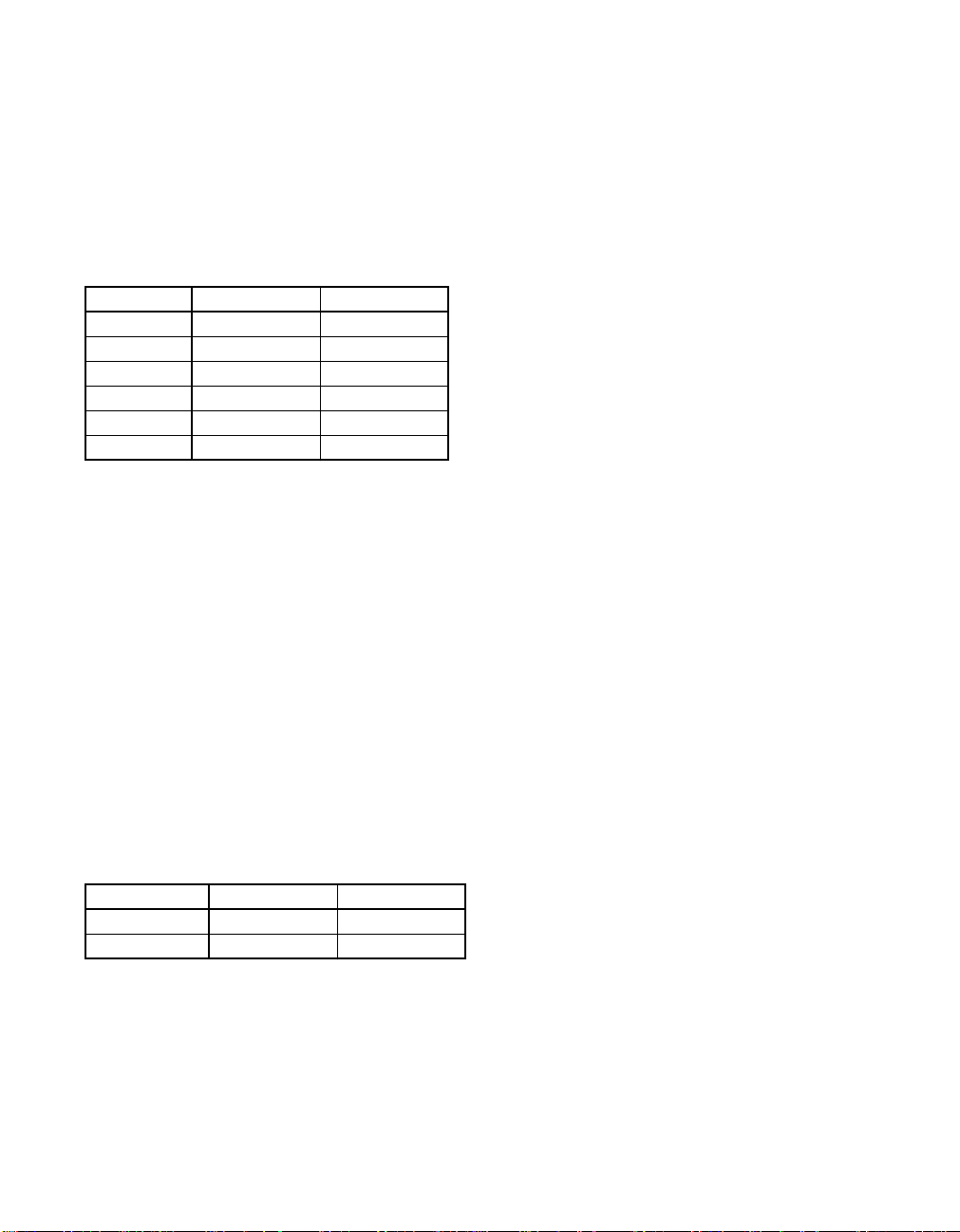
achieve a short cycle time (see Table 1-1). The pipeline is organized so that large
scalarity (four), short latencies, and multiple bypasses do not affect the cycle time
significantly.
Table 1-1 Implementation Technologies and Cycle Times
UltraSPARC-I UltraSPARC-II
Technology 0.5 µ CMOS 0.35 µCMOS
Artisan Technology Group - Quality Instrumentation ... Guaranteed | (888) 88-SOURCE | www.artisantg.com

1. UltraSPARC Basics
1.3 Component Overview
Figure 1-1 shows a block diagram of the UltraSPARC processor.
Figure 1-1 UltraSPARC Block Diagram
The block diagram illustrates the following components:
• Prefetch and Dispatch Unit (PDU), including logic for branch prediction
• 16Kb Instruction Cache (I-Cache)
• Memory Management Unit (MMU), containing a 64-entry Instruction
Translation Lookaside Buffer (iTLB) and a 64-entry Data Translation
Ext.
Cache
RAM
Prefetch and Dispatch Unit (PDU)
Integer Execution Unit (IEU)
Floating Point Unit (FPU)
Graphics Unit (GRU)
Instruction Cache and Buffer
Grouping Logic Integer Reg and Annex
FP
Reg
FP Multiply
FP Add
FP Divide
Load / Store Unit (LSU)
Data Load Store
External Cache Unit (ECU)
Memory Management Unit (MMU)
Memory Interface Unit (MIU)
System Interconnect
Cache Buffer Buffer
iTLB dTLB
Artisan Technology Group - Quality Instrumentation ... Guaranteed | (888) 88-SOURCE | www.artisantg.com

UltraSPARC User’s Manual
• Integer Execution Unit (IEU) with two Arithmetic and Logic Units (ALUs)
• Load/Store Unit (LSU) with a separate address generation adder
• Load buffer and store buffer, decoupling data accesses from the pipeline
• A 16Kb Data Cache (D-Cache)
• Floating-Point Unit (FPU) with independent add, multiply, and divide/square
root sub-units
• Graphics Unit (GRU) with two independent execution pipelines
• External Cache Unit (ECU), controlling accesses to the External Cache
(E-Cache)
• Memory Interface Unit (MIU), controlling accesses to main memory and I/O
space
1.3.1 Prefetch and Dispatch Unit (PDU)
The prefetch and dispatch unit fetches instructions before they are actually needed in the pipeline, so the execution units do not starve for instructions. Instructions can be prefetched from all levels of the memory hierarchy; that is, from the
instruction cache, the external cache, and main memory. In order to prefetch
across conditional branches, a dynamic branch prediction scheme is implemented
in hardware. The outcome of a branch is based on a two-bit history of the branch.
A “next field” associated with every four instructions in the instruction cache
(I-Cache) points to the next I-Cache line to be fetched. The use of the next field
makes it possible to follow taken branches and to provide nearly the same instruction bandwidth achieved while running sequential code. Prefetched instructions are stored in the Instruction Buffer until they are sent to the rest of the
pipeline; up to 12 instructions can be buffered.
1.3.2 Instruction Cache (I-Cache)
The instruction cache is a 16 Kbyte two-way set associative cache with 32 byte
blocks. The cache is physically indexed and contains physical tags. The set is predicted as part of the “next field;” thus, only the index bits of an address (13 bits,
which matches the minimum page size) are needed to address the cache. The
I-Cache returns up to 4 instructions from an 8-instruction-wide cache line.
Sun Microelectronics
6
Artisan Technology Group - Quality Instrumentation ... Guaranteed | (888) 88-SOURCE | www.artisantg.com

1. UltraSPARC Basics
1.3.3 Integer Execution Unit (IEU)
The IEU contains the following components:
• Two ALUs
• A multi-cycle integer multiplier
• A multi-cycle integer divider
• Eight register windows
• Four sets of global registers (normal, alternate, MMU, and interrupt globals)
• The trap registers (See Table 1-2 for supported trap levels)
1.3.4 Floating-Point Unit (FPU)
The FPU is partitioned into separate execution units, which allows the
UltraSPARC processor to issue and execute two floating-point instructions per
cycle. Source and result data are stored in the 32-entry register file, where each
entry can contain a 32-bit value or a 64-bit value. Most instructions are fully pipelined, (with a throughput of one per cycle), have a latency of three, and are not
affected by the precision of the operands (same latency for single- or double-precision). The divide and square root instructions are not pipelined and take 12/22
cycles (single/double) to execute but they do not stall the processor. Other instructions, following the divide/square root can be issued, executed, and retired
to the register file before the divide/square root finishes. A precise exception
model is maintained by synchronizing the floating-point pipe with the integer
pipe and by predicting traps for long latency operations. See Section 7.3.1, “Precise Traps,” in The SPARC Architecture Manual, Version 9.
1.3.5 Graphics Unit (GRU)
UltraSPARC introduces a comprehensive set of graphics instructions that provide
fast hardware support for two-dimensional and three-dimensional image and
video processing, image compression, audio processing, etc. 16-bit and 32-bit partitioned add, boolean, and compare are provided. 8-bit and 16-bit partitioned
multiplies are supported. Single cycle pixel distance, data alignment, packing,
Table 1-2 Supported Trap Levels
UltraSPARC-I UltraSPARC-II
MAXTL 44
Trap Levels 55
Artisan Technology Group - Quality Instrumentation ... Guaranteed | (888) 88-SOURCE | www.artisantg.com

The MMU provides mapping between a 44-bit virtual address and a 41-bit physical address. This is accomplished through a 64-entry iTLB for instructions and a
64-entry dTLB for data; both TLBs are fully associative. UltraSPARC provides
hardware support for a software-based TLB miss strategy. A separate set of global registers is available to process MMU traps. Page sizes of 8Kb (13-bit offset),
64Kb (16-bit offset), 512Kb (19-bit offset), and 4Mb (22-bit offset) are supported.
The LSU is responsible for generating the virtual address of all loads and stores
(including atomics and ASI loads), for accessing the D-Cache, for decoupling
load misses from the pipeline through the Load Buffer, and for decoupling stores
through the Store Buffer. One load or one store can be issued per cycle.
The D-Cache is a write-through, non-allocating, 16Kb direct-mapped cache with
two 16-byte sub-blocks per line. It is virtually indexed and physically tagged
(VIPT). The tag array is dual ported, so tag updates due to line fills do not collide
with tag reads for incoming loads. Snoops to the D-Cache use the second tag
port, so they do not delay incoming loads.
The main role of the ECU is to handle I-Cache and D-Cache misses efficiently.
The ECU can handle one access per cycle to the External Cache (E-Cache). Accesses to the E-Cache are pipelined, which effectively makes the E-Cache part of
the instruction pipeline. Programs with large data sets can keep data in the
E-Cache and can schedule instructions with load latencies based on E-Cache latency. Floating-point code can use this feature to effectively hide D-Cache misses.
Table 1-5 on page 10 shows the E-Cache sizes that each UltraSPARC model supports. Regardless of model, however, the E-Cache line size is always 64 bytes.
UltraSPARC uses a MOESI (Modified, Own, Exclusive, Shared, Invalid) protocol
Artisan Technology Group - Quality Instrumentation ... Guaranteed | (888) 88-SOURCE | www.artisantg.com
1. UltraSPARC Basics
The ECU provides overlap processing during load and store misses. For instance,
stores that hit the E-Cache can proceed while a load miss is being processed. The
ECU can process reads and writes indiscriminately, without a costly turn-around
penalty (only 2 cycles). Finally, the ECU handles snoops.
Block loads and block stores, which load/store a 64-byte line of data from memory to the floating-point register file, are also processed efficiently by the ECU,
providing high transfer bandwidth without polluting the E-Cache.
1.3.9.1 E-Cache SRAM Modes
Different UltraSPARC models support various E-Cache SRAM configurations using one or more SRAM “modes.” Table 1-5 shows the modes that each
UltraSPARC model supports. The modes are described below.
1–1–1 (Pipelined) Mode:
The E-Cache SRAMS have a cycle time equal to the processor cycle time. The
name “1–1–1” indicates that it takes one processor clock to send the address, one
to access the SRAM array, and one to return the E-Cache data. 1–1–1 mode has a
3 cycle pin-to-pin latency and provides the best possible E-Cache throughput.
2–2 (Register-Latched) Mode:
The E-Cache SRAMS have a cycle time equal to one-half the processor cycle time.
The name “2–2” indicates that it takes two processor clocks to send the address
and two clocks to access and return the E-Cache data. 2–2 mode has a 4 cycle pin-
Table 1-3 Supported E-Cache Sizes
E-Cache Size UltraSPARC-I UltraSPARC-II
512 Kb ✓✓
1 Mb ✓✓
2 Mb ✓✓
4 Mb ✓✓
8 Mb ✓
16 Mb ✓
Table 1-4 Supported E-Cache SRAM Modes
SRAM Mode UltraSPARC-I UltraSPARC-II
1–1–1 ✓✓
2–2 ✓
Artisan Technology Group - Quality Instrumentation ... Guaranteed | (888) 88-SOURCE | www.artisantg.com

The MIU handles all transactions to the system controller; for example, external
cache misses, interrupts, snoops, writebacks, and so on. The MIU communicates
with the system at some model-dependent fraction of the UltraSPARC frequency.
Table 1-5 shows the possible ratios between the processor and system clock frequencies for each UltraSPARC model.
Figure 1-2 shows a complete UltraSPARC subsystem, which consists of the
UltraSPARC processor, synchronous SRAM components for the E-Cache tags and
data, and two UltraSPARC Data Buffer (UDB) chips. The UDBs isolate the
E-Cache from the system, provide data buffers for incoming and outgoing system
transactions, and provide ECC generation and checking.
Table 1-5 Model-Dependent Processor : System Clock Frequency Ratios
Frequency Ratio UltraSPARC-I UltraSPARC-II
2 : 1 ✓✓
3 : 1 ✓✓
4 : 1 ✓
E-Cache Data SRAM
UDB
E-Cache Tag SRAM
System
Data Bus
System
Address Bus
E-Cache Data
Tag Data
Tag Address
Data Address
UltraSPARC
Processor
Artisan Technology Group - Quality Instrumentation ... Guaranteed | (888) 88-SOURCE | www.artisantg.com

Processor Pipeline 2
2.1 Introductions
UltraSPARC contains a 9-stage pipeline. Most instructions go through the pipeline in exactly 9 stages. The instructions are considered terminated after they go
through the last stage (W), after which changes to the processor state are irreversible. Figure 2-1 shows a simplified diagram of the integer and floating-point pipeline stages.
Figure 2-1 UltraSPARC Pipeline Stages (Simplified)
Three additional stages are added to the integer pipeline to make it symmetrical
with the floating-point pipeline. This simplifies pipeline synchronization and exception handling. It also eliminates the need to implement a floating-point queue.
Floating-point instructions with a latency greater than three (divide, square root,
and inverse square root) behave differently than other instructions; the pipe is
“extended” when the instruction reaches stage N1. See Chapter 16, “Code Generation Guidelines” for more information. Memory operations are allowed to proceed asynchronously with the pipeline in order to support latencies longer than
Fetch Decode Group Execute Cache N
1
N
2
N
3
Write
Integer Pipeline
Register X
1
X
2
X
3
Floating-Point &
Graphics Pipeline
Artisan Technology Group - Quality Instrumentation ... Guaranteed | (888) 88-SOURCE | www.artisantg.com

This section describes each pipeline stage in detail. Figure 2-2 illustrates the pipeline stages.
Figure 2-2 UltraSPARC Pipeline Stages (Detail)
X
1
IU Register File
EC
N
1
N
2
G
D-Cache
TLB
FP add
FP RF 32 x 64
IST_data
Icc
FPST_data
Annex
FPU
IEU
G ALU
FP mul
G mul
GRU
address bus
data bus
instruction bus
LSU
Tag
Tag Check
Hit
align
VA
PA
N
3
W
(Results in Annex)
ECU
LDQ/STQ
D-Cache
Data
R
X
2
X
3
SB
Artisan Technology Group - Quality Instrumentation ... Guaranteed | (888) 88-SOURCE | www.artisantg.com

2.2.1 Stage 1: Fetch (F) Stage
Prior to their execution, instructions are fetched from the Instruction Cache
(I-Cache) and placed in the Instruction Buffer, where eventually they will be selected to be executed. Accessing the I-Cache is done during the F Stage. Up to
four instructions are fetched along with branch prediction information, the predicted target address of a branch, and the predicted set of the target. The high
bandwidth provided by the I-Cache (4 instructions/cycle) allows UltraSPARC to
prefetch instructions ahead of time based on the current instruction flow and on
branch prediction. Providing a fetch bandwidth greater than or equal to the maximum execution bandwidth assures that, for well behaved code, the processor
does not starve for instructions. Exceptions to this rule occur when branches are
hard to predict, when branches are very close to each other, or when the I-Cache
miss rate is high.
2.2.2 Stage 2: Decode (D) Stage
After being fetched, instructions are pre-decoded and then sent to the Instruction
Buffer. The pre-decoded bits generated during this stage accompany the instructions during their stay in the Instruction Buffer. Upon reaching the next stage
(where the grouping logic lives) these bits speed up the parallel decoding of up
to 4 instructions.
2. Processor Pipeline
While it is being filled, the Instruction Buffer also presents up to 4 instructions to
the next stage. A pair of pointers manage the Instruction Buffer, ensuring that as
many instructions as possible are presented in order to the next stage.
2.2.3 Stage 3: Grouping (G) Stage
The G Stage logic’s main task is to group and dispatch a maximum of four valid
instructions in one cycle. It receives a maximum of four valid instructions from
the Prefetch and Dispatch Unit (PDU), it controls the Integer Core Register File
(ICRF), and it routes valid data to each integer functional unit. The G Stage sends
up to two floating-point or graphics instructions out of the four candidates to the
Floating-Point and Graphics Unit (FGU). The G Stage logic is responsible for
comparing register addresses for integer data bypassing and for handling pipeline stalls due to interlocks.
Sun Microelectronics
13
Artisan Technology Group - Quality Instrumentation ... Guaranteed | (888) 88-SOURCE | www.artisantg.com

UltraSPARC User’s Manual
2.2.4 Stage 4: Execution (E) Stage
Data from the integer register file is processed by the two integer ALUs during
this cycle (if the instruction group includes ALU operations). Results are computed and are available for other instructions (through bypasses) in the very next cycle. The virtual address of a memory operation is also calculated during the E
Stage, in parallel with ALU computation.
FLOATING-POINT AND GRAPHICS UNIT: The Register (R) Stage of the FGU. The
floating-point register file is accessed during this cycle. The instructions are also
further decoded and the FGU control unit selects the proper bypasses for the current instructions.
2.2.5 Stage 5: Cache Access (C) Stage
The virtual address of memory operations calculated in the E Stage is sent to the
tag RAM to determine if the access (load or store type) is a hit or a miss in the
D-Cache. In parallel the virtual address is sent to the data MMU to be translated
into a physical address. On a load when there are no other outstanding loads, the
data array is accessed so that the data can be forwarded to dependent instructions in the pipeline as soon as possible.
ALU operations executed in the E Stage generate condition codes in the C Stage.
The condition codes are sent to the PDU, which checks whether a conditional
branch in the group was correctly predicted. If the branch was mispredicted, earlier instructions in the pipe are flushed and the correct instructions are fetched.
The results of ALU operations are not modified after the E Stage; the data merely
propagates down the pipeline (through the annex register file), where it is available for bypassing for subsequent operations.
FLOATING-POINT AND GRAPHICS UNIT: The X1 Stage of the FGU. Floating-point and
graphics instructions start their execution during this stage. Instructions of latency one also finish their execution phase during the X1Stage.
2.2.6 Stage 6: N1 Stage
A data cache miss/hit or a TLB miss/hit is determined during the N1 Stage. If a
load misses the D-Cache, it enters the Load Buffer. The access will arbitrate for
the E-Cache if there are no older unissued loads. If a TLB miss is detected, a trap
will be taken and the address translation is obtained through a software routine.
Sun Microelectronics
14
Artisan Technology Group - Quality Instrumentation ... Guaranteed | (888) 88-SOURCE | www.artisantg.com

The physical address of a store is sent to the Store Buffer during this stage. To
avoid pipeline stalls when store data is not immediately available, the store address and data parts are decoupled and sent to the Store Buffer separately.
FLOATING-POINT AND GRAPHICS UNIT: The X2stage of the FGU. Execution continues for most operations.
2.2.7 Stage 7: N2 Stage
Most floating-point instructions finish their execution during this stage. After N2,
data can be bypassed to other stages or forwarded to the data portion of the Store
Buffer. All loads that have entered the Load Buffer in N1 continue their progress
through the buffer; they will reappear in the pipeline only when the data comes
back. Normal dependency checking is performed on all loads, including those in
the load buffer.
FLOATING-POINT AND GRAPHICS UNIT: The X3stage of the FGU.
2.2.8 Stage 8: N3 Stage
UltraSPARC resolves traps at this stage.
2. Processor Pipeline
2.2.9 Stage 9: Write (W) Stage
All results are written to the register files (integer and floating-point) during this
stage. All actions performed during this stage are irreversible. After this stage, instructions are considered terminated.
Sun Microelectronics
15
Artisan Technology Group - Quality Instrumentation ... Guaranteed | (888) 88-SOURCE | www.artisantg.com

UltraSPARC User’s Manual
Sun Microelectronics
16
Artisan Technology Group - Quality Instrumentation ... Guaranteed | (888) 88-SOURCE | www.artisantg.com

Cache Organization 3
3.1 Introduction
3.1.1 Level-1 Caches
UltraSPARC’s Level-1 D-Cache is virtually indexed, physically tagged (VIPT).
Virtual addresses are used to index into the D-Cache tag and data arrays while
accessing the D-MMU (that is, the dTLB). The resulting tag is compared against
the translated physical address to determine D-Cache hits.
A side-effect inherent in a virtual-indexed cache is address aliasing; this issue is
addressed in Section 5.2.1, “Address Aliasing Flushing,” on page 28.
UltraSPARC’s Level-1 I-Cache is physically indexed, physically tagged (PIPT).
The lowest 13 bits of instruction addresses are used to index into the I-Cache tag
and data arrays while accessing the I-MMU (that is, the iTLB). The resulting tag
is compared against the translated physical address to determine I-Cache hits.
3.1.1.1 Instruction Cache (I-Cache)
The I-Cache is a 16 Kb pseudo-two-way set-associative cache with 32-byte blocks.
The set is predicted based on the next fetch address; thus, only the index bits of
an address are necessary to address the cache (that is, the lowest 13 bits, which
matches the minimum page size of 8Kb). Instruction fetches bypass the instruction cache under the following conditions:
• When the I-Cache enable or I-MMU enable bits in the LSU_Control_Register
are clear (see Section A.6, “LSU_Control_Register,” on page 306)
Artisan Technology Group - Quality Instrumentation ... Guaranteed | (888) 88-SOURCE | www.artisantg.com

• When the I-MMU maps the fetch as noncacheable.
The instruction cache snoops stores from other processors or DMA transfers, but
it is not updated by stores in the same processor, except for block commit stores
(see Section 13.6.4, “Block Load and Store Instructions,” on page 230). The
FLUSH instruction can be used to maintain coherency. Block commit stores update the I-Cache but do not flush instructions that have already been prefetched
into the pipeline. A FLUSH, DONE, or RETRY instruction can be used to flush
the pipeline. For block copies that must maintain I-Cache coherency, it is more efficient to use block commit stores in the loop, followed by a single FLUSH instruction to flush the pipeline.
Note: The size of each I-Cache set is the same as the page size in UltraSPARC-I
and UltraSPARC-II; thus, the virtual index bits equal the physical index bits.
The D-Cache is a write-through, nonallocating-on-write-miss 16-Kb direct
mapped cache with two 16-byte sub-blocks per line. Data accesses bypass the
data cache when the D-Cache enable bit in the LSU_Control_Register is clear (see
Section A.6, “LSU_Control_Register,” on page 306). Load misses will not allocate
in the D-Cache if the D-MMU enable bit in the LSU_Control_Register is clear or
the access is mapped by the D-MMU as virtual noncacheable.
Note: A noncacheable access may access data in the D-Cache from an earlier
cacheable access to the same physical block, unless the D-Cache is disabled.
Software must flush the D-Cache when changing a physical page from cacheable
to noncacheable (see Section 5.2, “Cache Flushing”).
UltraSPARC’s level-2 (external) cache (the E-Cache) is physically indexed, physically tagged (PIPT). This cache has no references to virtual address and context
information. The operating system needs no knowledge of such caches after initialization, except for stable storage management and error handling.
Memory accesses must be cacheable in the E-Cache to allow use of UltraSPARC’s
ECC checking. As a result, there is no E-Cache enable bit in the
Artisan Technology Group - Quality Instrumentation ... Guaranteed | (888) 88-SOURCE | www.artisantg.com

3. Cache Organization
Instruction fetches bypass the E-Cache when:
• The I-MMU is disabled, or
• The processor is in RED_state, or
• The access is mapped by the I-MMU as physically noncacheable
Data accesses bypass the E-Cache when:
• The D-MMU enable bit (DM) in the LSU_Control_Register is clear, or
• The access is mapped by the D-MMU as nonphysical cacheable (unless
ASI_PHYS_USE_EC is used).
The system must provide a noncacheable, ECC-less scratch memory for use of the
booting code until the MMUs are enabled.
The E-Cache is a unified, write-back, allocating, direct-mapped cache. The
E-Cache always includes the contents of the I-Cache and D-Cache. The E-Cache
size is model dependent (see Table 1-5 on page 10); its line size is 64 bytes.
Block loads and block stores, which load or store a 64-byte line of data from
memory to the floating-point register file, do not allocate into the E-Cache, in order to avoid pollution.
Artisan Technology Group - Quality Instrumentation ... Guaranteed | (888) 88-SOURCE | www.artisantg.com

UltraSPARC User’s Manual
Sun Microelectronics
20
Artisan Technology Group - Quality Instrumentation ... Guaranteed | (888) 88-SOURCE | www.artisantg.com

Overview of the MMU 4
4.1 Introduction
This chapter describes the UltraSPARC Memory Management Unit as it is seen by
the operating system software. The UltraSPARC MMU conforms to the requirements set forth in The SPARC Architecture Manual, Version 9.
Note: The UltraSPARC MMU does not conform to the SPARC-V8 Reference
MMU Specification. In particular, the UltraSPARC MMU supports a 44-bit virtual
address space, software TLB miss processing only (no hardware page table walk),
simplified protection encoding, and multiple page sizes. All of these differ from
features required of SPARC-V8 Reference MMUs.
4.2 Virtual Addr ess T ranslation
The UltraSPARC MMU supports four page sizes: 8 Kb, 64 Kb, 512 Kb, and 4 Mb.
It supports a 44-bit virtual address space, with 41 bits of physical address. During
each processor cycle the UltraSPARC MMU provides one instruction and one
data virtual-to-physical address translation. In each translation, the virtual page
number is replaced by a physical page number, which is concatenated with the
page offset to form the full physical address, as illustrated in Figure 4-1 on page
22. (This figure shows the full 64-bit virtual address, even though UltraSPARC
supports only 44 bits of VA.)
Artisan Technology Group - Quality Instrumentation ... Guaranteed | (888) 88-SOURCE | www.artisantg.com

Figure 4-1 Virtual-to-physical Address Translation for all Page Sizes
UltraSPARC implements a 44-bit virtual address space in two equal halves at the
extreme lower and upper portions of the full 64-bit virtual address space. Virtual
addresses between 0000 0800 0000 000016 and FFFF F7FF FFFF FFFF16, inclusive,
are termed “out of range” for UltraSPARC and are illegal. (In other words, virtual
address bits VA<63:43> must be either all zeros or all ones.) Figure 4-2 on page 23
illustrates the UltraSPARC virtual address space.
0
0
12
1213
13
63
40
8K-byte Virtual Page Number
8K-byte Physical Page Number
Page Offset
Page Offset
0
0
15
1516
16
63
40
64K-byte Virtual Page Number
64K-byte Physical Page Number
Page Offset
Page Offset
0
0
18
18
19
1963
40
512K-byte Virtual Page Number
512K-byte PPN
Page Offset
Page Offset
VA
PA
PA
PA
VA
VA
8 Kb
64 Kb
512 Kb
0
0
21
21
22
22
63
40
4M-byte Virtual Page Number
4M-byte PPN
Page Offset
Page Offset
PA
VA
4 Mb
MMU
MMU
MMU
MMU
Artisan Technology Group - Quality Instrumentation ... Guaranteed | (888) 88-SOURCE | www.artisantg.com

4. Overview of the MMU
Figure 4-2 UltraSPARC’s 44-bit Virtual Address Space, with Hole (Same as Figure 14-2)
Note: Throughout this document, when virtual address fields are specified as
64-bit quantities, they are assumed to be sign-extended based on VA<43>.
The operating system maintains translation information in a data structure called
the Software Translation Table. The I- and D-MMU each contain a hardware
Translation Lookaside Buffer (iTLB and dTLB); these act as independent caches of
the Software Translation Table, providing one-cycle translation for the more frequently accessed virtual pages.
Figure 4-3 on page 24 shows a general software view of the UltraSPARC MMU.
The TLBs, which are part of the MMU hardware, are small and fast. The Software
Translation Table, which is kept in memory, is likely to be large and complex. The
Translation Storage Buffer (TSB), which acts like a direct-mapped cache, is the interface between the two. The TSB can be shared by all processes running on a
processor, or it can be process specific. The hardware does not require any particular scheme.
The term “TLB hit” means that the desired translation is present in the MMU’s
on-chip TLB. The term “TLB miss” means that the desired translation is not
present in the MMU’s on-chip TLB. On a TLB miss the MMU immediately traps
to software for TLB miss processing. The TLB miss handler has the option of filling the TLB by any means available, but it is likely to take advantage of the TLB
miss support features provided by the MMU, since the TLB miss handler is time
critical code. Hardware support is described in Section 6.3.1, “Hardware Support
FFFF FFFF FFFF FFFF
FFFF F800 0000 0000
0000 0000 0000 0000
0000 07FF FFFF FFFF
Out of Range VA
(VA “Hole”)
FFFF F7FF FFFF FFFF
0000 0800 0000 0000
Artisan Technology Group - Quality Instrumentation ... Guaranteed | (888) 88-SOURCE | www.artisantg.com

UltraSPARC User’s Manual
Translation
Look-aside
Buffers
MMU Memory O/S Data Structure
Figure 4-3 Software View of the UltraSPARC MMU
Translation
Storage
Buffer
Software
Translation
Table
Aliasing between pages of different size (when multiple VAs map to the same
PA) may take place, as with the SPARC-V8 Reference MMU. The reverse case,
when multiple mappings from one VA/context to multiple PAs produce a multiple TLB match, is not detected in hardware; it produces undefined results.
Note: The hardware ensures the physical reliability of the TLB on multiple
matches.
Sun Microelectronics
24
Artisan Technology Group - Quality Instrumentation ... Guaranteed | (888) 88-SOURCE | www.artisantg.com

Section II — Going Deeper
5. Cache and Memory Interactions ...................................................... 27
6. MMU Internal Architecture ............................................................... 41
7. UltraSPARC External Interfaces ....................................................... 73
8. Address Spaces, ASIs, ASRs, and Traps .......................................... 145
9. Interrupt Handling ............................................................................. 161
10. Reset and RED_state .......................................................................... 169
11. Error Handling .................................................................................... 175
Artisan Technology Group - Quality Instrumentation ... Guaranteed | (888) 88-SOURCE | www.artisantg.com

UltraSPARC User’s Manual
Sun Microelectronics
26
Artisan Technology Group - Quality Instrumentation ... Guaranteed | (888) 88-SOURCE | www.artisantg.com

Cache and Memory Interactions 5
5.1 Introduction
This chapter describes various interactions between the caches and memory, and
the management processes that an operating system must perform to maintain
data integrity in these cases. In particular, it discusses:
• When and how to invalidate one or more cache entries
• The differences between cacheable and non-cacheable accesses
• The ordering and synchronization of memory accesses
• Accesses to addresses that cause side effects (I/O accesses)
• Non-faulting loads
• Instruction prefetching
• Load and store buffers
This chapter only address coherence in a uniprocessor environment. For more information about coherence in multi-processor environments, see Chapter 15,
“SPARC-V9 Memory Models.”
5.2 Cache Flushing
Data in the level-1 (read-only or write-through) caches can be flushed by invalidating the entry in the cache. Modified data in the level-2 (writeback) cache must
Artisan Technology Group - Quality Instrumentation ... Guaranteed | (888) 88-SOURCE | www.artisantg.com

Cache flushing is required in the following cases:
I-Cache:
Flush is needed before executing code that is modified by a local store instruction
other than block commit store, see Section 3.1.1.1, “Instruction Cache (I-Cache).”
This is done with the FLUSH instruction or using ASI accesses. See Section A.7,
“I-Cache Diagnostic Accesses,” on page 309. When ASI accesses are used, software must ensure that the flush is done on the same processor as the stores that
modified the code space.
D-Cache:
Flush is needed when a physical page is changed from (virtually) cacheable to
(virtually) noncacheable, or when an illegal address alias is created (see Section
5.2.1, “Address Aliasing Flushing,” on page 28). This is done with a displacement
flush (see Section 5.2.3, “Displacement Flushing,” on page 29) or using ASI
accesses. See Section A.8, “D-Cache Diagnostic Accesses,” on page 314.
E-Cache:
Flush is needed for stable storage. Examples of stable storage include batterybacked memory and transaction logs. This is done with either a displacement
flush (see Section 5.2.3, “Displacement Flushing,” on page 29) or a store with
ASI_BLK_COMMIT_{PRIMARY,SECONDARY}. Flushing the E-Cache will flush
the corresponding blocks from the I- and D-Caches, because UltraSPARC maintains inclusion between the external and internal caches. See Section 5.2.2, “Committing Block Store Flushing,” on page 29.
A side-effect inherent in a virtual-indexed cache is illegal address aliasing. Aliasing
occurs when multiple virtual addresses map to the same physical address. Since
UltraSPARC’s D-Cache is indexed with the virtual address bits and is larger than
the minimum page size, it is possible for the different aliased virtual addresses to
end up in different cache blocks. Such aliases are illegal because updates to one
cache block will not be reflected in aliased cache blocks.
Normally, software avoids illegal aliasing by forcing aliases to have the same address bits (virtual color) up to an alias boundary. For UltraSPARC, the minimum
alias boundary is 16Kb; this size may increase in future designs. When the alias
boundary is violated, software must flush the D-Cache if the page was virtual
cacheable. In this case, only one mapping of the physical page can be allowed in
the D-MMU at a time. Alternatively, software can turn off virtual caching of illegally aliased pages. This allows multiple mappings of the alias to be in the
D-MMU and avoids flushing the D-Cache each time a different mapping is refer-
Artisan Technology Group - Quality Instrumentation ... Guaranteed | (888) 88-SOURCE | www.artisantg.com

5. Cache and Memory Interactions
Note: A change in virtual color when allocating a free page does not require a
D-Cache flush, because the D-Cache is write-through.
5.2.2 Committing Block Store Flushing
In UltraSPARC, stable storage must be implemented by software cache flush.
Data that is present and modified in the E-Cache must be written back to the stable storage.
UltraSPARC implements two ASIs (ASI_BLK_COMMIT_{PRIMARY,SECONDARY}) to perform these writebacks efficiently when software can ensure exclusive
write access to the block being flushed. Using these ASIs, software can write back
data from the floating-point registers to memory and invalidate the entry in the
cache. The data in the floating-point registers must first be loaded by a block load
instruction. A MEMBAR #Sync instruction is needed to ensure that the flush is
complete. See also Section 13.6.4, “Block Load and Store Instructions,” on page
230.
5.2.3 Displacement Flushing
Cache flushing also can be accomplished by a displacement flush. This is done by
reading a range of read-only addresses that map to the corresponding cache line
being flushed, forcing out modified entries in the local cache. Care must be taken
to ensure that the range of read-only addresses is mapped in the MMU before
starting a displacement flush, otherwise the TLB miss handler may put new data
into the caches.
Note: Diagnostic ASI accesses to the E-Cache can be used to invalidate a line,
but they are generally not an alternative to displacement flushing. Modified data
in the E-Cache will not be written back to memory using these ASI accesses. See
Section A.9, “E-Cache Diagnostics Accesses,” on page 315.
5.3 Memory Accesses and Cacheability
Note: Atomic load-store instructions are treated as both a load and a store; they
can be performed only in cacheable address spaces.
Artisan Technology Group - Quality Instrumentation ... Guaranteed | (888) 88-SOURCE | www.artisantg.com

Two types of memory operations are supported in UltraSPARC: cacheable and
noncacheable accesses, as indicated by the page translation. Cacheable accesses
are inside the coherence domain; noncacheable accesses are outside the coherence
domain.
SPARC-V9 does not specify memory ordering between cacheable and noncacheable accesses. In TSO mode, UltraSPARC maintains TSO ordering, regardless of
the cacheability of the accesses. For SPARC-V9 compatibility while in PSO or
RMO mode, a MEMBAR #Lookaside should be used between a store and a subsequent load to the same noncacheable address. See Section 8, “Memory Models,”
in The SPARC Architecture Manual, Version 9 for more information about the
SPARC-V9 memory models.
Note: On UltraSPARC, a MEMBAR #Lookaside executes more efficiently than
a MEMBAR #StoreLoad.
Accesses that fall within the coherence domain are called cacheable accesses.
They are implemented in UltraSPARC with the following properties:
• Data resides in real memory locations.
• They observe supported cache coherence protocol(s).
• The unit of coherence is 64 bytes.
Accesses that are outside the coherence domain are called noncacheable accesses.
Some of these memory (-mapped) locations may have side-effects when accessed.
They are implemented in UltraSPARC with the following properties:
• Data may or may not reside in real memory locations.
• Accesses may result in program-visible side-effects; for example, memory-
mapped I/O control registers in a UART may change state when read.
• They may not observe supported cache coherence protocol(s).
Artisan Technology Group - Quality Instrumentation ... Guaranteed | (888) 88-SOURCE | www.artisantg.com

5. Cache and Memory Interactions
Noncacheable accesses with the E-bit set (that is, those having side-effects) are all
strongly ordered with respect to other noncacheable accesses with the E-bit set. In
addition, store buffer compression is disabled for these accesses. Speculative
loads with the E-bit set cause a
data_access_exception
trap (with SFSR.FT=2, spec-
ulative load to page marked with E-bit).
Note: The side-effect attribute does not imply noncacheability.
5.3.1.3 Global V isibility and Memory Ordering
A memory access is considered globally visible when it has been acknowledged
by the system. In order to ensure the correct ordering between the cacheable and
noncacheable domains, explicit memory synchronization is needed in the form of
MEMBARs or atomic instructions. Code Example 5-1 illustrates the issues involved in mixing cacheable and noncacheable accesses.
Code Example 5-1 Memory Ordering and MEMBAR Examples
Assume that all accesses go to non-side-effect memory locations.
Process A:
While (1)
{
Store D1:data produced
1 MEMBAR #StoreStore (needed in PSO, RMO)
Store F1:set flag
While F1 is set (spin on flag)
Load F1
2 MEMBAR #LoadLoad | #LoadStore (needed in RMO)
Load D2
}
Process B:
While (1)
{
While F1 is cleared (spin on flag)
Load F1
2 MEMBAR #LoadLoad | #LoadStore (needed in RMO)
Load D1
Store D2
1 MEMBAR #StoreStore (needed in PSO, RMO)
Store F1:clear flag
Artisan Technology Group - Quality Instrumentation ... Guaranteed | (888) 88-SOURCE | www.artisantg.com

Note: A MEMBAR #MemIssue or MEMBAR #Sync is needed if ordering of
cacheable accesses following noncacheable accesses must be maintained in PSO
or RMO.
Due to load and store buffers implemented in UltraSPARC, the above example
may not work in PSO and RMO modes without the MEMBARs shown in the program segment.
In TSO mode, loads and stores (except block stores) cannot pass earlier loads, and
stores cannot pass earlier stores; therefore, no MEMBAR is needed.
In PSO mode, loads are completed in program order, but stores are allowed to
pass earlier stores; therefore, only the MEMBAR at #1 is needed between updating data and the flag.
In RMO mode, there is no implicit ordering between memory accesses; therefore,
the MEMBARs at both #1 and #2 are needed.
The MEMBAR (STBAR in SPARC-V8) and FLUSH instructions are provide for explicit control of memory ordering in program execution. MEMBAR has several
variations; their implementations in UltraSPARC are described below. See Section
A.31, “Memory Barrier,” Section 8.4.3, “The MEMBAR Instruction,” and Section J,
“Programming With the Memory Models,” in The SPARC Architecture Manual,
Version 9 for more information.
Forces all loads after the MEMBAR to wait until all loads before the MEMBAR
have reached global visibility.
Forces all loads after the MEMBAR to wait until all stores before the MEMBAR
have reached global visibility.
Forces all stores after the MEMBAR to wait until all loads before the MEMBAR
Artisan Technology Group - Quality Instrumentation ... Guaranteed | (888) 88-SOURCE | www.artisantg.com

5.3.2.4 MEMBAR #StoreStore and STBAR
Forces all stores after the MEMBAR to wait until all stores before the MEMBAR
have reached global visibility.
Note: STBAR has the same semantics as MEMBAR #StoreStore; it is included
for SPARC-V8 compatibility.
Note: The above four MEMBARs do not guarantee ordering between cacheable
accesses after noncacheable accesses.
5.3.2.5 MEMBAR #Lookaside
SPARC-V9 provides this variation for implementations having virtually tagged
store buffers that do not contain information for snooping.
Note: For SPARC-V9 compatibility, this variation should be used before issuing
a load to an address space that cannot be snooped.
5. Cache and Memory Interactions
5.3.2.6 MEMBAR #MemIssue
Forces all outstanding memory accesses to be completed before any memory access instruction after the MEMBAR is issued. It must be used to guarantee ordering of cacheable accesses following non-cacheable accesses. For example, I/O
accesses must be followed by a MEMBAR #MemIssue before subsequent cacheable stores; this ensures that the I/O accesses reach global visibility before the
cacheable stores after the MEMBAR.
Note: MEMBAR #MemIssue is different from the combination of MEMBAR
#LoadLoad | #LoadStore | #StoreLoad | #StoreStore. MEMBAR
#MemIssue orders cacheable and noncacheable domains; it prevents memory
accesses after it from issuing until it completes.
5.3.2.7 MEMBAR #Sync (Issue Barrier)
Forces all outstanding instructions and all deferred errors to be completed before
any instructions after the MEMBAR are issued.
Sun Microelectronics
33
Artisan Technology Group - Quality Instrumentation ... Guaranteed | (888) 88-SOURCE | www.artisantg.com
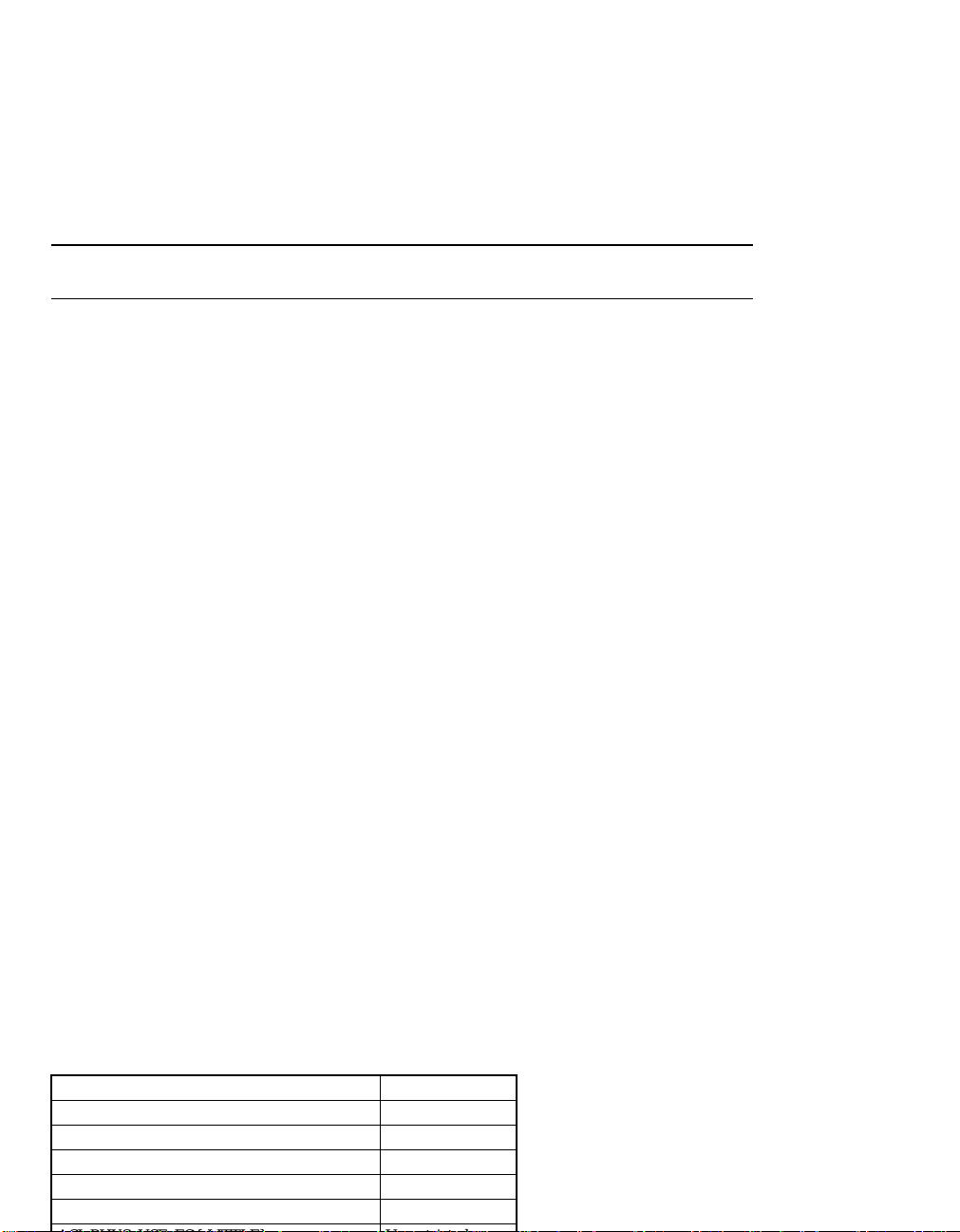
Note: MEMBAR #Sync is a costly instruction; unnecessary usage may result in
substantial performance degradation.
The SPARC-V9 instruction set architecture does not guarantee consistency between code and data spaces. A problem arises when code space is dynamically
modified by a program writing to memory locations containing instructions. LISP
programs and dynamic linking require this behavior. SPARC-V9 provides the
FLUSH instruction to synchronize instruction and data memory after code space
has been modified.
In UltraSPARC, a FLUSH behaves like a store instruction for the purpose of
memory ordering. In addition, all instruction (pre-)fetch buffers are invalidated.
The issue of the FLUSH instruction is delayed until previous (cacheable) stores
are completed. Instruction (pre-)fetch resumes at the instruction immediately after the FLUSH.
SPARC-V9 provides three atomic instructions to support mutual exclusion. These
instructions behave like both a load and a store, but the operations are carried out
indivisibly. Atomic instructions may be used only in the cacheable domain.
An atomic access with a restricted ASI in unprivileged mode (PSTATE.PRIV=0)
causes a
privileged_action
trap. An atomic access with a noncacheable address caus-
es a
data_access_exception
trap (with SFSR.FT=4, atomic to page marked non-
cacheable). An atomic access with an unsupported ASI causes a
data_access_exception
trap (with SFSR.FT=8, illegal ASI value or virtual address).
Table 5-1 lists the ASIs that support atomic accesses.
Table 5-1 ASIs that Support SWAP, LDSTUB, and CAS
ASI Name Access
ASI_NUCLEUS{_LITTLE} Restricted
ASI_AS_IF_USER_PRIMARY{_LITTLE} Restricted
ASI_AS_IF_USER_SECONDARY{_LITTLE} Restricted
ASI_PRIMARY{_LITTLE} Unrestricted
ASI_SECONDARY{_LITTLE} Unrestricted
Artisan Technology Group - Quality Instrumentation ... Guaranteed | (888) 88-SOURCE | www.artisantg.com

Note: Atomic accesses with non-faulting ASIs are not allowed, because these
ASIs have the load-only attribute.
5.3.3.1 SW AP Instruction
SWAP atomically exchanges the lower 32 bits in an integer register with a word
in memory. This instruction is issued only after store buffers are empty. Subsequent loads interlock on earlier SWAPs. A cache miss will allocate the corresponding line.
Note: If a page is marked as virtually-non-cacheable but physically cacheable,
allocation is done to the E-Cache only.
5.3.3.2 LDSTUB Instruction
LDSTUB behaves like SWAP, except that it loads a byte from memory into an integer register and atomically writes all ones (FF16) into the addressed byte.
5. Cache and Memory Interactions
5.3.3.3 Compare and Swap (CASX) Instruction
Compare-and-swap combines a load, compare, and store into a single atomic instruction. It compares the value in an integer register to a value in memory; if
they are equal, the value in memory is swapped with the contents of a second integer register. All of these operations are carried out atomically; in other words,
no other memory operation may be applied to the addressed memory location
until the entire compare-and-swap sequence is completed.
5.3.4 Non-Faulting Load
A non-faulting load behaves like a normal load, except that:
• It does not allow side-effect access. An access with the E-bit set causes a
data_access_exception
E-bit).
trap (with SFSR.FT=2, Speculative Load to page marked
• It can be applied to a page with the NFO-bit set; other types of accesses will
cause a
marked NFO).
data_access_exception
trap (with SFSR.FT=1016, Normal access to page
Sun Microelectronics
35
Artisan Technology Group - Quality Instrumentation ... Guaranteed | (888) 88-SOURCE | www.artisantg.com

Non-faulting loads are issued with ASI_PRIMARY_NO_FAULT{_LITTLE}, or
ASI_SECONDARY_NO_FAULT{_LITTLE}. A store with a NO_FAULT ASI causes
a
data_access_exception
trap (with SFSR.FT=8, Illegal RW).
When a non-faulting load encounters a TLB miss, the operating system should attempt to translate the page. If the translation results in an error (for example, address out of range), a 0 is returned and the load completes silently.
Typically, optimizers use non-faulting loads to move loads before conditional
control structures that guard their use. This technique potentially increases the
distance between a load of data and the first use of that data, in order to hide latency; it allows for more flexibility in code scheduling. It also allows for improved performance in certain algorithms by removing address checking from
the critical code path.
For example, when following a linked list, non-faulting loads allow the null
pointer to be accessed safely in a read-ahead fashion if the OS can ensure that the
page at virtual address 016 is accessed with no penalty. The NFO (non-fault access
only) bit in the MMU marks pages that are mapped for safe access by non-faulting loads, but can still cause a trap by other, normal accesses. This allows programmers to trap on wild pointer references (many programmers count on an
exception being generated when accessing address 016 to debug code) while benefitting from the acceleration of non-faulting access in debugged library routines.
Table 5-2 shows which UltraSPARC models support the PREFETCH{A} instructions.
UltraSPARC models that do not support PREFETCH treat it as a NOP.
UltraSPARC processors that do support PREFETCH behave in the following
ways:
• All PREFETCH instructions are enqueued on the load buffer, except as noted
Table 5-2 PREFETCH{A} Instruction Support
UltraSPARC-I UltraSPARC-II
PREFETCH{A} ✓
Artisan Technology Group - Quality Instrumentation ... Guaranteed | (888) 88-SOURCE | www.artisantg.com

5. Cache and Memory Interactions
• Some conditions, noted below, cause an otherwise supported PREFETCH to
be treated as a NOP and removed from the load buffer when it reaches the
front of the queue.
• No PREFETCH will cause a trap except:
• PREFETCH with fcn=5..15 causes an
illegal_instruction
trap, as defined in The
SPARC Architecture Manual, Version 9.
• Watchpoint, as defined in Section A.5, “Watchpoint Support,” on page 304.
• Any PREFETCHA that specifies an internal ASI in the following ranges is not
enqueued on the load buffer and is not executed:
• 4016..4F16, 5016..5F16, 6016..6F16, 7616, 77
16
• The following conditions cause a PREFETCH{A} to be treated as a NOP:
• PREFECTH with fcn=16..31, as defined in The SPARC Architecture Manual,
Version 9.
• A
data_access_MMU_miss
exception
• D-MMU disabled
• For PREFETCHA, any ASI other than the following 0416, 0C16, 1016, 1116,
1816, 1916, 8016..8316, 8816..8B
16
• Attempt to PREFETCH to a noncacheable page
• Alignment is not checked on PREFETCH{A}. The 5 least significant address
are ignored.
5.3.5.2 Implemented fcn V alues
Table 5-3 lists the supported values for fcn and their meanings.
For more information, including an enumeration of the bus transaction the each
fcn value causes, see Section 14.4.5, “PREFETCH{A} (Impdep #103, 117),” on page
Table 5-3 PREFETCH{A} Variants
fcn Prefetch Function
0 Prefetch for several reads
1 Prefetch for one read
2 Prefetch page
3 Prefetch for several writes
4 Prefetch for one write
5..15
illegal_instruction
trap
16..31 NOP
Artisan Technology Group - Quality Instrumentation ... Guaranteed | (888) 88-SOURCE | www.artisantg.com

Block load and store instructions work like normal floating-point load and store
instructions, except that the data size (granularity) is 64 bytes per transfer. See
Section 13.6.4, “Block Load and Store Instructions,” on page 230 for a full description of the instructions.
I/O locations may not behave with memory semantics. Loads and stores may
have side-effects; for example, a read access may clear a register or pop an entry
off a FIFO. A write access may set a register address port so that the next access
to that address will read or write a particular internal registers, etc. Such devices
are considered order sensitive. Also, such devices may only allow accesses of a
fixed size, so store buffer merging of adjacent stores or stores within a 16-byte region will cause an access error.
The UltraSPARC MMU includes an attribute bit (the E-Bit) in each page translation, which, when set, indicates that access to this page cause side effects. Accesses other than block loads or stores to pages that have this bit set have the
following behavior:
• Noncacheable accesses are strongly ordered with respect to each other
• Noncacheable loads with the E-bit set will not be issued until all previous
control transfers (including exceptions) are resolved.
• Store buffer compression is disabled for noncacheable accesses.
• Non-faulting loads are not allowed and will cause a
data_access_exception
trap
(with SFSR.FT = 2, speculative load to page marked E-bit).
• A MEMBAR may be needed between side-effect and non-side-effect accesses
while in PSO and RMO modes.
UltraSPARC does instruction prefetching and follows branches that it predicts
will be taken. Addresses mapped by the I-MMU may be accessed even though
they are not actually executed by the program. Normally, locations with side effects or those that generate time-outs or bus errors will not be mapped by the
I-MMU, so prefetching will not cause problems. When running with the I-MMU
disabled, however, software must avoid placing data in the path of a control
transfer instruction target or sequentially following a trap or conditional branch
Artisan Technology Group - Quality Instrumentation ... Guaranteed | (888) 88-SOURCE | www.artisantg.com

5. Cache and Memory Interactions
CALL, or JMPL instruction. Instructions should not be placed within 256 bytes of
locations with side effects. See Section 16.2.10, “Return Address Stack (RAS),” on
page 272 for other information about JMPLs and RETURNs.
5.3.9 Instruction Prefetch When Exiting RED_state
Exiting RED_state by writing 0 to PSTATE.RED in the delay slot of a JMPL is not
recommended. A noncacheable instruction prefetch may be made to the JMPL
target, which may be in a cacheable memory area. This may result in a bus error
on some systems, which will cause an
instruction_access_error
trap. The trap can be
masked by setting the NCEEN bit in the ESTATE_ERR_EN register to zero, but
this will mask all non-correctable error checking. To avoid this problem exit
RED_state with DONE or RETRY, or with a JMPL to a noncacheable target address.
5.3.10 UltraSPARC Internal ASIs
ASIs in the ranges 4616.. 6F16 and 7616..7F16 are used for accessing internal
UltraSPARC states. Stores to these ASIs do not follow the normal memory model
ordering rules. Correct operation requires the following:
• A MEMBAR #Sync is needed after an internal ASI store other than MMU
ASIs before the point that side effects must be visible. This MEMBAR must
precede the next load or noninternal store. The MEMBAR also must be in or
before the delay slot of a delayed control transfer instruction of any type. This
is necessary to avoid corrupting data.
• A FLUSH, DONE, or RETRY is needed after an internal store to the MMU
ASIs (ASI 5016..5216, 5416..5F16) or to the IC bit in the LSU control register
before the point that side effects must be visible. Stores to D-MMU registers
other than the context ASIs may also use a MEMBAR #Sync. One of these
instructions must precede the next load or noninternal store. They also must
be in or before the delay slot of a delayed control transfer instruction. This is
necessary to avoid corrupting data.
5.4 Load Buffer
The load buffer allows the load and execution pipelines in UltraSPARC to be decoupled; thus, loads that cannot return data immediately will not stall the pipeline, but rather, will be buffered until they can return data. For example, when a
load misses the on-chip D-Cache and must access the E-Cache, the load will be
Artisan Technology Group - Quality Instrumentation ... Guaranteed | (888) 88-SOURCE | www.artisantg.com

long as they do not require the register that is being loaded. An instruction that
attempts to use the data that is being loaded by an instruction in the load buffer
is called a ‘use’ instruction.
The pipelines are not fully decoupled, because UltraSPARC still supports the notion of precise traps, and loads that are younger than a trapping instruction must
not execute, except in the case of deferred traps. Loads themselves can take precise traps, when exceptions are detected in the pipeline. For example, address
misalignment or access violations detected in the translation process will both be
reported as precise traps. However, when a load has a hardware problem on the
external bus (for example, a parity error), it will generate a deferred trap, since
younger instructions, unblocked by the D-Cache miss, could have been retired
and modified the machine state. This may result in termination of the user thread
or reset. UltraSPARC does not support recovery from such hardware errors, and
they are fatal. See Chapter 11.1 , “Error Handling.”
All store operations (including atomic and STA instructions) and barriers or store
completion instructions (MEMBAR and STBAR) are entered into the Store Buffer.
The store buffer normally has lower priority than the load buffer when arbitrating for the D-Cache or E-Cache, since returning load data is usually more critical
than store completion. To ensure that stores complete in a finite amount of time
as required by SPARC-V9, UltraSPARC eventually will raise the store buffer priority above load buffer priority if the store buffer is continually locked out by
subsequent loads (other than internal ASI loads). Software using a load spin loop
to wait for a signal from another processor following a store that signals that processor will wait for the store to time out in the store buffer. For this type of code,
it is more efficient to put a MEMBAR #StoreLoad between the store and the
load spin loop.
Consecutive non-side-effect stores may be combined into aligned 16-byte entries
in the store buffer to improve store bandwidth. Cacheable stores can only be compressed with adjacent cacheable stores, Likewise, noncacheable stores can only be
compressed with adjacent noncacheable stores. In order to maintain strong ordering for I/O accesses, stores with the side-effect attribute (E-bit set) cannot be
Artisan Technology Group - Quality Instrumentation ... Guaranteed | (888) 88-SOURCE | www.artisantg.com

MMU Internal Architecture 6
6.1 Introduction
This chapter provides detailed information about the UltraSPARC Memory Management Unit. It describes the internal architecture of the MMU and how to program it.
6.2 T ranslation Table Entry (TTE)
The Translation Table Entry, illustrated in Figure 6-1, is the UltraSPARC equivalent of a SPARC-V8 page table entry; it holds information for a single page mapping. The TTE is broken into two 64-bit words, representing the tag and data of
the translation. Just as in a hardware cache, the tag is used to determine whether
there is a hit in the TSB. If there is a hit, the data is fetched by software.
Figure 6-1 Translation Table Entry (TTE) (from TSB)
G: Global. If the Global bit is set, the Context field of the TTE is ignored
during hit detection. This allows any page to be shared among all (user
or supervisor) contexts running in the same processor. The Global bit is
duplicated in the TTE tag and data to optimize the software miss handler.
G VA_tag<63:22>Context
063
Tag
Data
414248 47
—
62 6061
—
PA<40:13>Size Soft
011363 41
CVCP
2312
WP
4
Diag
61 6062 5
GV E
6L7
Soft2
5059
NFO
49 40
IE
58
Artisan Technology Group - Quality Instrumentation ... Guaranteed | (888) 88-SOURCE | www.artisantg.com

VA_tag<63:22>: Virtual Address Tag. The virtual page number. Bits 21 through 13
are not maintained in the tag, since these bits are used to index the
smallest direct-mapped TSB of 64 entries.
Note: Software must sign-extend bits VA_tag<63:44> to form an in-range VA.
V: Valid: If the Valid bit is set, the remaining fields of the TTE are
meaningful. Note that the explicit Valid bit is redundant with the
software convention of encoding an invalid TTE with an unused context.
The encoding of the context field is necessary to cause a failure in the TTE
tag comparison, while the explicit Valid bit in the TTE data simplifies the
TLB miss handler.
Size: The page size of this entry, encoded as shown in the following table.
NFO: No-Fault-Only. If this bit is set, loads with
ASI_PRIMARY_NO_FAULT{_LITTLE},
ASI_SECONDARY_NO_FAULT{_LITTLE} are translated. Any other
access will trap with a
data_access_exception
trap (FT=1016). The NFO-bit
in the I-MMU is read as zero and ignored when written. If this bit is set
before loading the TTE into the TLB, the iTLB miss handler should
generate an error.
IE: Invert Endianness. If this bit is set, accesses to the associated page are
processed with inverse endianness from what is specified by the
instruction (big-for-little and little-for-big). See Section 6.6, “ASI Value,
Context, and Endianness Selection for Translation,” on page 52 for
details. In the I-MMU this bit is read as zero and ignored when written.
Note: This bit is intended to be set primarily for noncacheable accesses. The
performance of cacheable accesses will be degraded as if the access had missed
the D-Cache.
Table 6-1 Size Field Encoding (from TTE)
Size<1:0> Page Size
00 8 Kb
01 64 Kb
10 512 Kb
11 4 Mb
Artisan Technology Group - Quality Instrumentation ... Guaranteed | (888) 88-SOURCE | www.artisantg.com

6. MMU Internal Architecture
Soft<5:0>, Soft2<8:0>: Software-defined fields, provided for use by the operating
system. The Soft and Soft2 fields may be written with any value; they
read as zero.
Diag: Used by diagnostics to access the redundant information held in the TLB
structure. Diag<0>=Used bit, Diag<3:1>=RAM size bits, Diag<6:4>=CAM
size bits. (Size bits are 3-bit encoded as 000=8K, 001=64K, 011=512K,
111=4M.) The size bits are read-only; the Used bit is read/write. All other
Diag bits are reserved.
PA<40:13>: The physical page number. Page offset bits for larger page sizes
(PA<15:13>, PA<18:13>, and PA<21:13> for 64Kb, 512Kb, and 4Mb pages,
respectively) are stored in the TLB and returned for a Data Access read,
but ignored during normal translation.
L: Lock. If this bit is set, the TTE entry will be “locked down” when it is
loaded into the TLB; that is, if this entry is valid, it will not be replaced by
the automatic replacement algorithm invoked by an ASI store to the Data
In register. The lock bit has no meaning for an invalid entry. Arbitrary
entries may be locked down in the TLB. Software must ensure that at
least one entry is not locked when replacing a TLB entry, otherwise the
last TLB entry will be replaced.
CP, CV: The cacheable-in-physically-indexed-cache and cacheable-in-virtually-
indexed-cache bits determine the placement of data in UltraSPARC
caches, according to Table 6-2. The MMU does not operate on the
cacheable bits, but merely passes them through to the cache subsystem.
The CV-bit in the I-MMU is read as zero and ignored when written.
E: Side-effect. If this bit is set, speculative loads and FLUSHes will trap for
addresses within the page, noncacheable memory accesses other than
block loads and stores are strongly ordered against other E-bit accesses,
and noncacheable stores are not merged. This bit should be set for pages
that map I/O devices having side-effects. Note, however, that the E-bit
does not prevent normal instruction prefetching. The E-bit in the I-MMU
Table 6-2 Cacheable Field Encoding (from TSB)
Cacheable
{CP, CV}
Meaning of TTE When Placed in:
iTLB
(I-Cache PA-Indexed)
dTLB
(D-Cache VA-Indexed)
0x Non-cacheable Non-cacheable
10 Cacheable E-Cache, I-Cache Cacheable E-Cache only
11 Cacheable E-Cache, I-Cache Cacheable E-Cache, D-Cache
Artisan Technology Group - Quality Instrumentation ... Guaranteed | (888) 88-SOURCE | www.artisantg.com

Note: The E-bit does not force an uncacheable access. It is expected, but not
required, that the CP and CV bits will be set to zero when the E-bit is set.
P: Privileged. If the P bit is set, only the supervisor can access the page
mapped by the TTE. If the P bit is set and an access to the page is
attempted when PSTATE.PRIV=0, the MMU will signal an
instruction_access_exception
or
data_access_exception
trap (FT=116).
W: Writable. If the W bit is set, the page mapped by this TTE has write
permission granted. Otherwise, write permission is not granted and the
MMU will cause a
data_access_protection
trap if a write is attempted. The
W-bit in the I-MMU is read as zero and ignored when written.
G: Global. This bit must be identical to the Global bit in the TTE tag. Similar
to the case of the Valid bit, the Global bit in the TTE tag is necessary for
the TSB hit comparison, while the Global bit in the TTE data facilitates
the loading of a TLB entry.
Compatibility Note:
Referenced and Modified bits are maintained by software. The Global, Privileged,
and Writable fields replace the 3-bit ACC field of the SPARC-V8 Reference MMU
Page Translation Entry.
The TSB is an array of TTEs managed entirely by software. It serves as a cache of
the Software Translation Table, used to quickly reload the TLB in the event of a
TLB miss. The discussion in this section assumes the use of the hardware support
for TSB access described in Section 6.3.1, “Hardware Support for TSB Access,” on
page 45, although the operating system is not required to make use of this support hardware.
Inclusion of the TLB entries in the TSB is not required; that is, translation information may exist in the TLB that is not present in the TSB.
The TSB is arranged as a direct-mapped cache of TTEs. The UltraSPARC MMU
provides precomputed pointers into the TSB for the 8 Kb and 64 Kb page TTEs.
In each case, N least significant bits of the respective virtual page number are
used as the offset from the TSB base address, with N equal to log base 2 of the
number of TTEs in the TSB.
A bit in the TSB register allows the TSB 64 Kb pointer to be computed for the case
Artisan Technology Group - Quality Instrumentation ... Guaranteed | (888) 88-SOURCE | www.artisantg.com

6. MMU Internal Architecture
No hardware TSB indexing support is provided for the 512 Kb and 4 Mb page
TTEs. Since the TSB is entirely software managed, however, the operating system
may choose to place these larger page TTEs in the TSB by forming the appropriate pointers. In addition, simple modifications to the 8 Kb and 64 Kb index pointers provided by the hardware allow formation of an M-way set-associative TSB,
multiple TSBs per page size, and multiple TSBs per process.
The TSB exists as a normal data structure in memory, and therefore may be
cached. Indeed, the speed of the TLB miss handler relies on the TSB accesses hitting the level-2 cache at a substantial rate. This policy may result in some conflicts with normal instruction and data accesses, but the dynamic sharing of the
level-2 cache resource should provide a better overall solution than that provided
by a fixed partitioning.
Figure 6-2 shows both the common and shared TSB organization. The constant N
is determined by the Size field in the TSB register; it may range from 512 to 64K.
Figure 6-2 TSB Organization
6.3.1 Hardware Support for TSB Access
The MMU hardware provides services to allow the TLB miss handler to efficiently reload a missing TLB entry for an 8 Kb or 64 Kb page. These services include:
• Formation of TSB Pointers based on the missing virtual address.
• Formation of the TTE Tag Target used for the TSB tag comparison.
• Efficient atomic write of a TLB entry with a single store ASI operation.
Tag1 (8 bytes) Data1 (8 bytes)
0000
16
0008
16
TagN (8 bytes) DataN (8 bytes)
N
Lines in Common TSB
Tag1 (8 bytes) Data1 (8 bytes)
TagN (8 bytes) DataN (8 bytes)
2N Lines in Split TSB
Artisan Technology Group - Quality Instrumentation ... Guaranteed | (888) 88-SOURCE | www.artisantg.com

A typical TLB miss and refill sequence is as follows:
1. A TLB miss causes either an
instruction_access_MMU_miss
or a
data_access_MMU_miss
exception.
2. The appropriate TLB miss handler loads the TSB Pointers and the TTE Tag
Target with loads from the MMU alternate space
3. Using this information, the TLB miss handler checks to see if the desired
TTE exists in the TSB. If so, the TTE Data is loaded into the TLB Data In
register to initiate an atomic write of the TLB entry chosen by the
replacement algorithm.
4. If the TTE does not exist in the TSB, the TLB miss handler jumps to a more
sophisticated (and slower) TSB miss handler.
The virtual address used in the formation of the pointer addresses comes from
the Tag Access register, which holds the virtual address and context of the load or
store responsible for the MMU exception. See Section 6.9, “MMU Internal Registers and ASI Operations,” on page 55. (Note that there are no separate physical
registers in UltraSPARC hardware for the Pointer registers, but rather they are
implemented through a dynamic re-ordering of the data stored in the Tag Access
and the TSB registers.)
Pointers are provided by hardware for the most common cases of 8 Kb and 64 Kb
page miss processing. These pointers give the virtual addresses where the 8 Kb
and 64 Kb TTEs would be stored if either is present in the TSB.
N is defined to be the TSB_Size field of the TSB register; it ranges from 0 to 7.
Note that TSB_Size refers to the size of each TSB when the TSB is split.
For a shared TSB (TSB register split field=0):
8K_POINTER = TSB_Base<63:13+N> VA<21+N:13> 0000
64K_POINTER = TSB_Base<63:13+N> VA<24+N:16> 0000
For a split TSB (TSB register split field=1):
8K_POINTER = TSB_Base<63:14+N> 0 VA<21+N:13> 0000
64K_POINTER = TSB_Base<63:14+N> 1 VA<24+N:16> 0000
For a more detailed description of the pointer logic with pseudo-code and hardware implementation, see Section 6.11.3, “TSB Pointer Logic Hardware Descrip-
Artisan Technology Group - Quality Instrumentation ... Guaranteed | (888) 88-SOURCE | www.artisantg.com

6. MMU Internal Architecture
The TSB Tag Target (described in Section 6.9, “MMU Internal Registers and ASI
Operations,” on page 55) is formed by aligning the missing access VA (from the
Tag Access register) and the current context to positions found in the description
of the TTE tag. This allows an XOR instruction for TSB hit detection.
These items must be locked in the TLB to avoid an error condition: TLB-miss handler, TSB and linked data, asynchronous trap handlers and data.
These items must be locked in the TSB (not necessarily the TLB) to avoid an error
condition: TSB-miss handler and data, interrupt-vector handler and data.
6.3.2 Alternate Global Selection During TLB Misses
In the SPARC-V9 normal trap mode, the software is presented with an alternate
set of global registers in the integer register file. UltraSPARC provides an additional feature to facilitate fast handling of TLB misses. For the following traps, the
trap handler is presented with a special set of MMU globals:
fast_{instruction,da-
ta}_access_MMU_miss
,
{instruction,data}_access_exception
, and
fast_data_access_protection
. The
privileged_action
and *
mem_address_not_aligned
traps
use the normal alternate global registers.
Compatibility Note:
The
UltraSPARC MMU performs no hardware table walking. The MMU hard-
ware never directly reads or writes the TSB.
6.4 MMU-Related Faults and T raps
Table 6-3 lists the traps recorded by the MMU.
T able 6-3 MMU Traps
Trap Name Trap Cause
Registers Updated
(Stored State in MMU)
I-SFSR
I-Tag
Access
D-SFSR,
SFAR
D-Tag
Access
fast_instruction_access_MMU_miss
iTLB miss ✓
instruction_access_exception
Several (see below) ✓✓
1
fast_data_access_MMU_miss
dTLB miss ✓
data_access_exception
Several (see below) ✓✓
fast_data_access_protection
Protection violation ✓✓
privileged_action
Use of privileged ASI ✓
*
_watchpoint
Watchpoint hit ✓
*
_mem_address_not_aligned
Misaligned mem op ✓
Artisan Technology Group - Quality Instrumentation ... Guaranteed | (888) 88-SOURCE | www.artisantg.com

Note: The
fast_instruction_access_MMU_miss,fast_data_access_MMU_miss
, and
fast_data_access_protection
traps are generated instead of
instruction_access_MMU_miss,data_access_MMU_miss
, and
data_access_protection
traps, respectively.
This trap occurs when the I-MMU is unable to find a translation for an instruction access; that is, when the appropriate TTE is not in the iTLB.
This trap occurs when the I-MMU is enabled and one of the following happens:
• The I-MMU detects a privilege violation for an instruction fetch; that is, an
attempted access to a privileged page when PSTATE.PRIV=0.
• Virtual address out of range and PSTATE.AM is not set. See Section 14.1.6,
“44-bit Virtual Address Space,” on page 237. Note that the case of JMPL/
RETURN and branch-CALL-sequential are handled differently. The contents
of the I-Tag Access Register are undefined in this case, but are not needed by
software.
This trap occurs when the MMU is unable to find a translation for a data access;
that is, when the appropriate TTE is not in the data TLB for a memory operation.
This trap occurs when the D-MMU is enabled and one of the following happens:
(the D-MMU does not prioritize these)
• The D-MMU detects a privilege violation for a data or FLUSH instruction
access; that is, an attempted access to a privileged page when
PSTATE.PRIV=0.
• A speculative (non-faulting) load or FLUSH instruction issued to a page
marked with the side-effect (E-bit)=1.
• An atomic instruction (including 128-bit atomic load) issued to a memory
Artisan Technology Group - Quality Instrumentation ... Guaranteed | (888) 88-SOURCE | www.artisantg.com

6. MMU Internal Architecture
• An invalid LDA/STA ASI value, invalid virtual address, read to write-only
register, or write to read-only register, but not for an attempted user access to
a restricted ASI (see the
privileged_action
trap described below).
• An access (including FLUSH) with an ASI other than
ASI_{PRIMARY,SECONDARY}_NO_FAULT{_LITTLE} to a page marked with
the NFO (no-fault-only) bit.
• Virtual address out of range (including FLUSH) and PSTATE.AM is not set.
See Section 4.2, “Virtual Address Translation,” on page 21.
The
data_access_exception
trap also occurs when the D-MMU is disabled and one
the following occurs:
• Speculative (non-faulting) load or FLUSH instruction issued when
LSU_Control_Register.DP=0.
• An atomic instruction (including 128-bit atomic load) is issued using the
ASI_PHYS_BYPASS_EC_WITH_EBIT{_LITTLE} ASIs. In this case
SFSR.FT=0416.
6.4.5 Data_access_protection Trap
This trap occurs when the MMU detects a protection violation for a data access.
A protection violation is defined to be an attempted store to a page that does not
have write permission.
6.4.6 Privileged_action Trap
This trap occurs when an access is attempted using a restricted ASI while in nonprivileged mode (PSTATE.PRIV=0).
6.4.7 Watchpoint Trap
This trap occurs when watchpoints are enabled and the D-MMU detects a load or
store to the virtual or physical address specified by the VA Data Watchpoint Register
or the PA Data Watchpoint Register, respectively. See Section A.5, “Watchpoint Sup-
port,” on page 304.
6.4.8 Mem_address_not_aligned Trap
This trap occurs when a load, store, atomic, or JMPL/RETURN instruction with a
misaligned address is executed. The LSU signals this trap, but the D-MMU
Artisan Technology Group - Quality Instrumentation ... Guaranteed | (888) 88-SOURCE | www.artisantg.com

Table 6-4 on page 51 summarizes the behavior of the D-MMU; Table 6-5 on page
51 summarizes the behavior of the I-MMU for normal (non-UltraSPARC-internal)
ASIs. In each case, for all conditions the behavior of the MMU is given by one of
the following abbreviations:
The ASI is indicated by one the following abbreviations:
Note: The “*_LITTLE” versions of the ASIs behave the same as the big-endian
versions with regard to the MMU table of operations.
Other abbreviations include “W” for the writable bit, “E” for the side-effect bit,
and “P” for the privileged bit.
The tables do not cover the following cases:
• Invalid ASIs, ASIs that have no meaning for the opcodes listed, or non-
existent ASIs; for example, ASI_PRIMARY_NO_FAULT for a store or atomic.
Also, access to UltraSPARC internal registers other than LDXA, LDFA, STDFA
or STXA, except for I-Cache diagnostic accesses other than LDDA, STDFA or
STXA. See Section 8.3.2, “UltraSPARC (Non-SPARC-V9) ASI Extensions,” on
page 147. The MMU signals a
data_access_exception
trap (FT=0816) for this
Abbrev Meaning
OK Normal Translation
DMISS
data_access_MMU_miss
trap
DEXC
data_access_exception
trap
DPROT
data_access_protection
trap
IMISS
instruction_access_MMU_miss
trap
IEXC
instruction_access_exception
trap
Abbrev Meaning
NUC ASI_NUCLEUS*
PRIM Any ASI with PRIMARY translation, except *NO_FAULT”
SEC Any ASI with SECONDARY translation, except *NO_FAULT”
PRIM_NF ASI_PRIMARY_NO_FAULT*
SEC_NF ASI_SECONDARY_NO_FAULT*
U_PRIM ASI_AS_IF_USER_PRIMARY*
U_SEC ASI_AS_IF_USER_SECONDARY*
BYPASS ASI_PHYS_* and also other ASIs that require the MMU to perform a bypass operation
(such as D-Cache access)
Artisan Technology Group - Quality Instrumentation ... Guaranteed | (888) 88-SOURCE | www.artisantg.com

6. MMU Internal Architecture
• Attempted access using a restricted ASI in non-privileged mode. The MMU
signals a
privileged_action
exception for this case.
• An atomic instruction (including 128-bit atomic load) issued to a memory
address marked uncacheable in a physical cache (that is, with CP=0),
including cases in which the D-MMU is disabled. The MMU signals a
data_access_exception
trap (FT=0416) for this case.
• A data access (including FLUSH) with an ASI other than
ASI_{PRIMARY,SECONDARY}_NO_FAULT{_LITTLE} to a page marked with
the NFO (no-fault-only) bit. The MMU signals a
data_access_exception
trap
(FT=1016) for this case.
• Virtual address out of range (including FLUSH) and PSTATE.AM is not set.
The MMU signals a
Table 6-4 D-MMU Operations for Normal ASIs
Opcode
Load
FLUSH
Store or
Atomic
— 0 BYPASS —
—
PRIV
Mode
0 PRIM, SEC — DMISS OK DEXC OK DEXC
1 PRIM, SEC, NUC — DMISS OK OK
0—
1—DMISS OK OK DEXC DEXC
0 PRIM, SEC 0
1 PRIM, SEC, NUC 0 DMISS DPROT DPROT
1 BYPASS — Bypass. No traps when D-MMU enabled,
data_access_exception
Condition Behavior
ASI W
PRIM_NF, SEC_NF — DMISS OK DEXC DEXC DEXC
PRIM_NF, SEC_NF — DMISS OK DEXC
U_PRIM, U_SEC — DMISS OK DEXC OK DEXC
U_PRIM, U_SEC 0 DMISS DPROT DEXC DPROT DEXC
trap (FT=2016) for this case.
TLB
Miss
DMISS OK DEXC DEXC DEXC
DMISS DPROT DEXC DPROT DEXC
1 DMISS OK DEXC OK DEXC
1 DMISS OK OK
1 DMISS OK DEXC OK DEXC
E=0
P=0
E=0
P=1
privileged_action
PRIV=1.
E=1
P=0
E=1
P=1
Table 6-5 I-MMU Operations for Normal ASIs
Condition Behavior
PRIV Mode TLB Miss P=0 P=1
0 IMISS OK IEXC
1 IMISS OK
Sun Microelectronics
Artisan Technology Group - Quality Instrumentation ... Guaranteed | (888) 88-SOURCE | www.artisantg.com
51

See Section 8.3, “Alternate Address Spaces,” on page 146 for a summary of the
UltraSPARC ASI map.
The MMU uses a two-step process to select the context for a translation:
1. The ASI is determined (conceptually by the Integer Unit) from the
instruction, trap level, and the processor endian mode
2. The context register is determined directly from the ASI.
The ASI value and endianness (little or big) are determined for the I-MMU and
D-MMU respectively according to Table 6-6 and Table 6-7 on page 53.
Note: The secondary context is never used to fetch instructions. The I-MMU
uses the value stored in the D-MMU Primary Context register when using the
Primary Context identifier; there is no I-MMU Primary Context register.
Note: The endianness of a data access is specified by three conditions: the ASI
specified in the opcode or ASI register, the PSTATE current little endian bit, and
the D-MMU invert endianness bit. The D-MMU invert endianness bit does not
affect the ASI value recorded in the SFSR, but does invert the endianness that is
otherwise specified for the access.
Note: The D-MMU Invert Endianness (IE) bit inverts the endianness for all
accesses to translating ASIs, including LD/ST/Atomic alternates that have
specified an ASI. That is, LDXA [%g1]ASI_PRIMARY_LITTLE will be big-endian
if the IE bit is on. Accesses to non-translating ASIs are not affected by the
D-MMU’s IE bit. See Section 8.3, “Alternate Address Spaces,” on page 146 for
information about non-translating ASIs
Artisan Technology Group - Quality Instrumentation ... Guaranteed | (888) 88-SOURCE | www.artisantg.com

6. MMU Internal Architecture
1
Accesses to non-translating ASIs are always made in “big endian” mode, regardless of the setting of D-MMU.IE. See Section 8.3,
“Alternate Address Spaces,” on page 146 for information about non-translating ASIs.
The context register used by the data and instruction MMUs is determined from
the following table. A comprehensive list of ASI values can be found in the ASI
map in Section 8.3, “Alternate Address Spaces,” on page 146. The context register
selection is not affected by the endianness of the access.
a. Any ASI name containing the string “NUCLEUS”.
b. Any ASI name containing the string “PRIMARY”.
T able 6-6 ASI Mapping for Instruction Accesses
Condition for Instruction Access Resulting Action
PSTATE.TL Endianness ASI Value (in SFSR)
0 Big ASI_PRIMARY
> 0 Big ASI_NUCLEUS
Table 6-7 ASI Mapping for Data Accesses
Condition for Data Access Access Processed with:
Opcode
PSTATE.TLPSTATE.
CLE
D-MMU.
IE
Endianness
ASI Value
(Recorded in SFSR)
LD/ST/Atomic/FLUSH
0
0
0 Big
ASI_PRIMARY
1 Little
1
0 Little
ASI_PRIMARY_LITTLE
1 Big
> 0
0
0 Big
ASI_NUCLEUS
1 Little
1
0 Little
ASI_NUCLEUS_LITTLE
1 Big
LD/ST/Atomic Alternate
with specified ASI not
ending in “_LITTLE”
Don’t Care Don’t Care
0 Big
1
Specified ASI value from immediate
field in opcode or ASI register
1 Little
1
LD/ST/Atomic Alternate
with specified ASI
ending in ‘_LITTLE”
Don’t Care Don’t Care
0 Little
Specified ASI value from immediate
field in opcode or ASI register
1 Big
Table 6-8 I-MMU and D-MMU Context Register Usage
ASI Value Context Register
ASI_*NUCLEUS*
a
Nucleus (000016 hard-wired)
ASI_*PRIMARY*
b
Primary
ASI_*SECONDARY*
c
Secondary
All other ASI values (Not applicable, no translation)
Artisan Technology Group - Quality Instrumentation ... Guaranteed | (888) 88-SOURCE | www.artisantg.com

During global reset of the UltraSPARC CPU, the following actions occur:
• No change occurs in any block of the D-MMU.
• No change occurs in the datapath or TLB blocks of the I-MMU.
• The I-MMU resets its internal state machine to normal (non-suspended)
operation.
• The I-MMU and D-MMU Enable bits in the LSU Control Register (see Section
A.6, “LSU_Control_Register,” on page 306) are set to zero.
On entering RED_state, the following action occurs:
• The I-MMU and D-MMU Enable bits in the LSU_Control_Register are set to
zero.
Either MMU is defined to be disabled when its respective MMU Enable bit equals
0; also, the I-MMU is disabled whenever the CPU is in RED_state. The D-MMU is
enabled or disabled solely by the state of the D-MMU Enable bit.
When the D-MMU is disabled it truncates all accesses, behaving as if
ASI_PHYS_BYPASS_EC_WITH_EBIT had been used, notably with side effect bit
(E-bit)=1, P=0 and CP=0. Other attribute bit settings can be found in Section 6.10,
“MMU Bypass Mode,” on page 68. However, if a bypass ASI is used while the DMMU is disabled, the bypass operation behaves as it does when the D-MMU is
enabled; that is, the access is processed with the E and CP bits as specified by the
bypass ASI.
When the I-MMU is disabled, it truncates all instruction accesses and passes the
physically-cacheable bit (CP=0) to the cache system. The access will not generate
an
instruction_access_exception
trap.
When disabled, both the I-MMU and D-MMU correctly perform all LDXA and
STXA operations to internal registers, and traps are signalled just as if the MMU
were enabled. For instance, if a *NO_FAULT load is issued when the D-MMU is
disabled, the D-MMU signals a
data_access_exception
trap (FT=0216), since access-
es when the D-MMU is disabled have E=1.
Note: While the D-MMU is disabled, data in the D-Cache can be accessed only
using load and store alternates to the UltraSPARC internal D-Cache access ASI.
Normal loads and stores bypass the D-Cache. Data in the D-Cache cannot be
accessed using load or store alternates that use ASI_PHYS_*.
Artisan Technology Group - Quality Instrumentation ... Guaranteed | (888) 88-SOURCE | www.artisantg.com

6. MMU Internal Architecture
Note: No reset of the TLB is performed by a chip reset or by entering
RED_state. Before the MMUs are enabled, the operating system software must
explicitly write each entry with either a valid TLB entry or an entry with the
valid bit set to zero. The operation of the I-MMU or D-MMU in enabled mode is
undefined if the TLB valid bits have not been set explicitly beforehand.
6.8 Compliance with the SP ARC-V9 Annex F
The UltraSPARC MMU complies completely with Annex F, “SPARC-V9 MMU Requirements,” in The SPARC Architecture Manual, Version 9. Table 6-9 shows how
various protection modes can be achieved, if necessary, through the presence or
absence of a translation in the I- or D-MMU. Note that this behavior requires specialized TLB miss handler code to guarantee these conditions.
6.9 MMU Internal Registers and ASI Operations
6.9.1 Accessing MMU Registers
All internal MMU registers can be accessed directly by the CPU through
UltraSPARC-defined ASIs. Several of the registers have been assigned their own
ASI because these registers are crucial to the speed of the TLB miss handler. Allowing the use of %g0 for the address reduces the number of instructions to perform the access to the alternate space (by eliminating address formation).
See Section 6.10, “MMU Bypass Mode,” on page 68 for details on the behavior of
the MMU during all other UltraSPARC ASI accesses. For instance, to facilitate an
Table 6-9 MMU Compliance w/SPARC-V9 Annex F Protection Mode
Condition
Resultant
Protection Mode
TTE in
D-MMU
TTE in
I-MMU
Writable
Attribute Bit
Yes No 0 Read-only
No Yes Don’t Care Execute-only
Yes No 1 Read/Write
Yes Yes 0 Read-only/Execute
Yes Yes 1 Read/Write/Execute
Artisan Technology Group - Quality Instrumentation ... Guaranteed | (888) 88-SOURCE | www.artisantg.com

Warning – STXA to an MMU register requires either a MEMBAR #Sync, FLUSH,
DONE, or RETRY before the point that the effect must be visible to load / store /
atomic accesses. Either a FLUSH, DONE, or RETRY is needed before the point
that the effect must be visible to instruction accesses: MEMBAR #Sync is not
sufficient. In either case, one of these instructions must be executed before the
next non-internal store or load of any type and on or before the delay slot of a
DCTI of any type. This is necessary to avoid corrupting data.
If the low order three bits of the VA are non-zero in a LDXA/STXA to/from these
registers, a
mem_address_not_aligned
trap occurs. Writes to read-only, reads to
write-only, illegal ASI values, or illegal VA for a given ASI may cause a
data_access_exception
trap (FT=0816). (The hardware detects VA violations in only
an unspecified lower portion of the virtual address.)
Warning – UltraSPARC does not check for out-of-range virtual addresses during
an STXA to any internal register; it simply sign extends the virtual address based
on VA<43>. Software must guarantee that the VA is within range.
Writes to the TSB register, Tag Access register, and PA and VA Watchpoint Address Registers are not checked for out-of-range VA. No matter what is written to
the register, VA<63:43> will always be identical on a read.
Table 6-10 UltraSPARC MMU Internal Registers and ASI Operations
I-MMU
ASI
D-MMU
ASI
VA<63:0> Access Register or Operation Name
50
16
58
16
0
16
Read-only I-/D-TSB Tag Target Registers
—58168
16
Read/Write Primary Context Register
—581610
16
Read/Write Secondary Context Register
50
16
58
16
18
16
Read/Write I-/D-Synchronous Fault Status Registers
—581620
16
Read-only D Synchronous Fault Address Register
50
16
58
16
28
16
Read/Write I-/D-TSB Registers
50
16
58
16
30
16
Read/Write I-/D-TLB Tag Access Registers
—581638
16
Read/Write Virtual Watchpoint Address
—581640
16
Read/Write Physical Watchpoint Address
51
16
59
16
0
16
Read-only I-/D-TSB 8K Pointer Registers
52
16
5A
16
0
16
Read-only I-/D-TSB 64K Pointer Registers
—5B160
16
Read-only D-TSB Direct Pointer Register
54
16
5C
16
0
16
Write-only I-/D-TLB Data In Registers
55
16
5D
16
016..1F8
16
Read/Write I-/D-TLB Data Access Registers
56
16
5E
16
016..1F8
16
Read-only I-/D-TLB Tag Read Register
Artisan Technology Group - Quality Instrumentation ... Guaranteed | (888) 88-SOURCE | www.artisantg.com

6.9.2 I-/D-TSB Tag T arget Registers
The I- and D-TSB Tag Target registers are simply bit-shifted versions of the data
stored in the I- and D-Tag Access registers, respectively. Since the I- or D-Tag Access register is updated on an I- or D-TLB miss, respectively, the I- and D-Tag Target registers appear to software to be updated on an I or D TLB miss.
Context000 — VA<63:22>
63 61 47 4160 48 42 0
Figure 6-3 MMU Tag Target Registers (Two Registers)
I/D Context<12:0>: The context associated with the missing virtual address.
I/D VA<63:22>: The most significant bits of the missing virtual address.
6.9.3 Context Registers
The context registers are shared by the I- and D-MMUs. The Primary Context
Register is defined as follows:
6. MMU Internal Architecture
— PContext
63
Figure 6-4 D-MMU Primary Context Register
1312 0
PContext: Context identifier for the primary address space.
The Secondary Context register is defined as follows:
— SContext
63 1312 0
Figure 6-5 D-MMU Secondary Context Register
SContext: Context identifier for the secondary address space.
The Nucleus Context register is hardwired to zero:
0000000000000000000000000000000000000000000000000000000000000000
63 0
Figure 6-6 D-MMU Nucleus Context Register
Sun Microelectronics
57
Artisan Technology Group - Quality Instrumentation ... Guaranteed | (888) 88-SOURCE | www.artisantg.com

Compatibility Note
The single context register of the SPARC-V8 Reference MMU has been replaced in
UltraSPARC by the three context registers shown in Figures 6-4, 6-5, and 6-6.
Note: A STXA to the context registers requires either a MEMBAR #Sync,
FLUSH, DONE, or RETRY before the point that the effect must be visible to data
accesses. Either a FLUSH, DONE, or RETRY is needed before the point that the
effect must be visible to instruction accesses: MEMBAR #Sync is not sufficient. In
either case, one of these instructions must be executed before the next translating
or bypass store or load of any type. This is necessary to avoid corrupting data.
The I- and D-MMU each maintain their own SFSR register, which is defined as
follows:
Figure 6-7 I- and D-MMU Synchronous Fault Status Register Format
ASI: The ASI field records the 8-bit ASI associated with the faulting
instruction. This field is valid for both D-MMU and I-MMU SFSRs and
for all traps in which the FV bit is set. JMPL and RETURN
mem_address_not_aligned
traps set the default ASI, as does a trapping nonalternate load or store; that is, to ASI_PRIMARY for PSTATE.CLE=0, or
ASI_PRIMARY_LITTLE otherwise.
FT: The Fault Type field indicates the exact condition that caused the
recorded fault, according to Table 6-11. In the D-MMU the Fault Type
field is valid only for
data_access_exception
traps; there is no ambiguity in
all other MMU trap cases. Note that the hardware does not priorityencode the bits set in the fault type register; that is, multiple bits may be
set. The FT field in the D-MMU SFSR reads zero for traps other than
data_access_exception
. The FT field in the I-MMU SFSR always reads zero
for
instruction_access_MMU_miss
, and either 0116, 2016, or 4016 for
63 2324 15 1316 14 7 5 3 1642 0
— ASI
—
FT E W
OF
VW
CTP
R
Artisan Technology Group - Quality Instrumentation ... Guaranteed | (888) 88-SOURCE | www.artisantg.com

6. MMU Internal Architecture
E: Reports the side-effect bit (E) associated with the faulting data access or
FLUSH instruction. Set by FLUSH or translating ASI accesses (see Section
8.3, “Alternate Address Spaces,” on page 146) mapped by the TLB with
the E bit set and ASI_PHYS_BYPASS_EC_WITH_EBIT{_LITTLE} ASIs
(1516 and 1D16). Other cases that update the SFSR (including bypass or
internal ASI accesses) set the E bit to 0. It always reads as 0 in the I-MMU.
CT: Context register selection, as described in the following table. The context
is set to 112 when the access does not have a translating ASI (see Section
8.3, “Alternate Address Spaces,” on page 146).
PR: Privilege. Set if the faulting access occurred while in Privileged mode.
This field is valid for all traps in which the Fault Valid (FV) bit is set.
W: Write. Set if the faulting access indicated a data write operation (a store
or atomic load/store instruction). Always reads as 0 in the I-MMU SFSR.
OW: Overwrite. Set to one when the MMU detects a fault, if the Fault Valid bit
Table 6-11 MMU Synchronous Fault Status Register FT (Fault Type) Field
FT<6:0> Fault Type
01
16
Privilege violation
02
16
Speculative Load or Flush instruction to page marked with E-bit. This bit is zero for internal
ASI accesses.
04
16
Atomic (including 128-bit atomic load) to page marked uncacheable. This bit is zero for
internal ASI accesses, except for atomics to DTLB_DATA_ACCESS_REG (5D16), which
update according to the TLB entry accessed.
08
16
Illegal LDA/STA ASI value, VA, RW, or size. Excludes cases where 0216 and 0416 are set.
10
16
Access other than non-faulting load to page marked NFO. This bit is zero for internal ASI
accesses.
20
16
VA out of range (D-MMU and I-MMU branch, CALL, sequential)
40
16
VA out of range (I-MMU JMPL or RETURN)
Table 6-12 MMU SFSR Context ID Field Description
Context ID I-MMU Context D-MMU Context
00 Primary Primary
01 Reserved Secondary
10 Nucleus Nucleus
11 Reserved Reserved
Artisan Technology Group - Quality Instrumentation ... Guaranteed | (888) 88-SOURCE | www.artisantg.com

FV: Fault Valid. Set when the MMU detects a fault; it is cleared only on an
explicit ASI write of 0 to the SFSR register. When FV is not set, the values
of the remaining fields in the SFSR and SFAR are undefined.
The SFSR and the Tag Access registers both maintain state concerning a previous
translation causing an exception. The update policy for the SFSR and the Tag Access registers is shown in Table 6-4 on page 51.
Note: A
fast_{instruction,data}_access_MMU_miss
trap does not cause the SFSR or
SFAR to be written. In this case the D-SFAR information can be obtained from the
D Tag Access register.
There is no I-MMU Synchronous Fault Address register. Instead, software must
read the TPC register appropriately as discussed here.
For
instruction_access_MMU_miss
traps, TPC contains the virtual address that was
not found in the I-MMU TLB.
For
instruction_access_exception
traps, “privilege violation” fault type, TPC contains the virtual address of the instruction in the privileged page that caused the
exception.
For
instruction_access_exception
traps, “VA out of range” fault types, note that the
TPC in these cases contains only a 44-bit virtual address, which is sign-extended
based on bit VA<43> for read. Therefore, use the following methods to compute
the virtual address that was out of range:
• For the branch, CALL, and sequential exception case, the TPC contains the
lower 44 bits of the virtual address that is out of range. Because the hardware
sign-extends a read of the TPC register based on VA<43>, the contents of the
TPC register XORed with FFFF F000 0000 000016 will give the full 64-bit outof-range virtual address.
• For the JMPL or RETURN exception case, the TPC contains the virtual address
of the JMPL or RETURN instruction itself. Software must disassemble the
Artisan Technology Group - Quality Instrumentation ... Guaranteed | (888) 88-SOURCE | www.artisantg.com

6. MMU Internal Architecture
6.9.5.2 D-MMU Fault Address
The Synchronous Fault Address register contains the virtual memory address of
the fault recorded in the D-MMU Synchronous Fault Status register. There is no
I-SFAR, since the instruction fault address is found in the trap program counter
(TPC). The SFAR can be considered an additional field of the D-SFSR.
Figure 6-8 illustrates the D-SFAR.
Figure 6-8 D-MMU Synchronous Fault Address Register (SFAR) Format
Fault Address: The virtual address associated with the translation fault recorded
in the D-SFSR. This field is valid only when the D-SFSR Fault Valid (FV)
bit is set. This field is sign-extended based on VA<43>, so bits VA<63:44>
do not correspond to the virtual address used in the translation for the
case of a VA-out-of-range
data_access_exception
trap. (For this case,
software must disassemble the trapping instruction.)
6.9.6 I-/D- T ranslation Storage Buffer (TSB) Registers
The TSB registers provide information for the hardware formation of TSB pointers and tag target, to assist software in handling TLB misses quickly. If the TSB
concept is not employed in the software memory management strategy, and
therefore the pointer and tag access registers are not used, then the TSB registers
need not contain valid data.
Figure 6-9 illustrates the TSB register.
Figure 6-9 I-/D-TSB Register Format
I/D TSB_Base<63:13>: Provides the base virtual address of the Translation
Storage Buffer. Software must ensure that the TSB Base is aligned on a
boundary equal to the size of the TSB, or both TSBs in the case of a split
TSB.
Warning – Stores to the TSB registers are not checked for out-of-range violations.
Reads from these registers are sign-extended based on TSB_Base<43>.
63 0
Fault Address (VA<63:0>)
63 32 0
TSB_Base<63:13> (virtual) TSB_Size
13 12
Split
—
11
Artisan Technology Group - Quality Instrumentation ... Guaranteed | (888) 88-SOURCE | www.artisantg.com

Split: When Split=1, the TSB 64 Kb Pointer address is calculated assuming
separate (but abutting and equally-sized) TSB regions for the 8 Kb and
the 64 Kb TTEs. In this case, TSB_Size refers to the size of each TSB, and
therefore the TSB 8Kb Pointer address calculation is not affected by the
value of the Split bit. When Split=0, the TSB 64 Kb Pointer address is
calculated assuming that the same lines in the TSB are shared by 8 Kb
and 64 Kb TTEs, called a “common TSB” configuration.
Warning – In the “common TSB” configuration (TSB.Split=0), 8 Kb and 64 Kb
page TTEs can conflict, unless the TLB miss handler explicitly checks the TTE for
page size. Therefore, do not use the common TSB mode in an optimized handler.
For example, suppose an 8K page at VA=200016 and a 64K page at VA=10000
16
both exist, which is a legal situation. These both want to exist at the second TSB
line (line 1), and have the same VA tag of 0. Therefore, there is no way for the
miss handler to distinguish these TTEs based on the TTE tag alone, and unless it
reads the TTE data, it may load an incorrect TTE.
I/D TSB_Size: The Size field provides the size of the TSB according to the
following:
•Number of entries in the TSB (or each TSB if split)=512 × 2
TSB_Size
.
•Number of entries in the TSB ranges from 512 entries at TSB_Size=0
(8 Kb common TSB, 16 Kb split TSB), to 64 Kb entries at TSB_Size=7
(1 Mb common TSB, 2 Mb split TSB).
Note: Any update to the TSB register immediately affects the data that is
returned from later reads of the Tag Target and TSB Pointer registers.
In each MMU the Tag Access register is used as a temporary buffer for writing
the TLB Entry tag information. The Tag Access register may be updated during
either of the following operations:
1. When the MMU signals a trap due to a miss, exception, or protection. The
MMU hardware automatically writes the missing VA and the appropriate
Context into the Tag Access register to facilitate formation of the TSB Tag
Target register. See Table 6-4 on page 51 for the SFSR and Tag Access
register update policy.
2. An ASI write to the Tag Access register. Before an ASI store to the TLB
Data Access registers, the operating system must set the Tag Access
Artisan Technology Group - Quality Instrumentation ... Guaranteed | (888) 88-SOURCE | www.artisantg.com

6. MMU Internal Architecture
TLB Data In register for automatic replacement also uses the Tag Access
register, but typically the value written into the Tag Access register by the
MMU hardware is appropriate.
Note: Any update to the Tag Access registers immediately affects the data that
is returned from subsequent reads of the Tag Target and TSB Pointer registers.
The TLB Tag Access Registers are defined as follows:
VA<63:13> Context<12:0>
63 0
Figure 6-10 I/D MMU TLB Tag Access Registers
13 12
I/D VA<63:13>: The 51-bit virtual page number. Note that writes to this field are
not checked for out-of-range violation, but sign extended based on VA<43>.
Warning – Stores to the Tag Access registers are not checked for out-of-range
violations. Reads from these registers are sign-extended based on VA<43>.
I/D Context<12:0>: The 13-bit context identifier. This field reads zero when there
is no associated context with the access.
6.9.8 I-/D-TSB 8 Kb/64 Kb Pointer and Direct Pointer Registers
These registers are provided to help the software determine the location of the
missing or trapping TTE in the software-maintained TSB. The TSB 8 Kb and 64
Kb Pointer registers provide the possible locations of the 8 Kb and 64 Kb TTE, respectively. The Direct Pointer register is mapped by hardware to either the 8 Kb
or 64 Kb Pointer register in the case of a
cording to the known size of the trapping TTE. In the case of a 512 Kb or 4 Mb
page miss, the Direct Pointer register returns the pointer as if the miss were from
an 8 Kb page.
The TSB Pointer registers are implemented as a re-order of the current data
stored in the Tag Access register and the TSB register. If the Tag Access register or
TSB register is updated through a direct software write (via a STXA instruction),
then the Pointer registers values will be updated as well.
The bit that controls selection of 8K or 64K address formation for the Direct
Pointer register is a state bit in the D-MMU that is updated during a
data_access_protection
exception. It records whether the page that hit in the TLB
was an 64K page or a non-64K page, in which case 8K is assumed.
fast_data_access_protection
Sun Microelectronics
exception ac-
63
Artisan Technology Group - Quality Instrumentation ... Guaranteed | (888) 88-SOURCE | www.artisantg.com

The I-/D-TSB 8 Kb/64 Kb Pointer registers are defined as follows:
Figure 6-11 I-/D-MMU TSB 8 Kb/64 Kb Pointer and D-MMU Direct Pointer Register
VA<63:0>: The full virtual address of the TTE in the TSB, as determined by the
MMU hardware. Described in Section 6.3.1, “Hardware Support for TSB
Access,” on page 45. Note that this field is sign-extended based on
VA<43>.
Access to the TLB is complicated due to the need to provide an atomic write of a
TLB entry data item (tag and data) that is larger than 64 bits, the need to replace
entries automatically through the TLB entry replacement algorithm as well as
provide direct diagnostic access, and the need for hardware assist in the TLB miss
handler. Table 6-13 shows the effect of loads and stores on the Tag Access register
and the TLB.
Table 6-13 Effect of Loads and Stores on MMU Registers
Load
Tag Read
No effect.
Contents returned
No effect No effect
Tag Access No effect No effect
No effect.
Contents returned
Data In Trap with
data_access_exception
Data Access No effect
No effect.
Contents returned
No effect
Store
Tag Read Trap with
data_access_exception
Tag Access No effect No effect
Written with store
data
Data In
TLB entry determined by replacement policy written with contents
of Tag Access Register
TLB entry determined by
replacement policy written
with store data
No effect
Data Access
TLB entry specified by STXA
address written with contents of
Tag Access Register
TLB entry specified by
STXA address written with
store data
No effect
Written with VA and
63 0
VA<63:0>
Artisan Technology Group - Quality Instrumentation ... Guaranteed | (888) 88-SOURCE | www.artisantg.com

6. MMU Internal Architecture
The Data In and Data Access registers are the means of reading and writing the
TLB for all operations. The TLB Data In register is used for TLB-miss and TSBmiss handler automatic replacement writes; the TLB Data Access register is used
for operating system and diagnostic directed writes (writes to a specific TLB entry). Both types of registers have the same format, as follows:
Figure 6-12 MMU I-/D-TLB Data In/Access Registers
Refer to the description of the TTE data in Section 6.2, “Translation Table Entry
(TTE),” on page 41, for a complete description of the above data fields.
Operations to the TLB Data In register require the virtual address to be set to zero. The format of the TLB Data Access register virtual address is as follows:
Figure 6-13 MMU TLB Data Access Address, in Alternate Space
TLB Entry: The TLB Entry number to be accessed, in the range 0 .. 63.
The format for the Tag Read register is as follows:
Figure 6-14 I-/D-MMU TLB Tag Read Registers
I/D VA<63:13>: The 51-bit virtual page number. Page offset bits for larger page
sizes are stored in the TLB and returned for a Tag Read register read, but
ignored during normal translation; that is, VA<15:13>, VA<18:13>, and
VA<21:13> for 64Kb, 512Kb and 4Mb pages, respectively. Note that this
field is sign-extended based on VA<43>.
I/D Context<12:0>: The 13-bit context identifier.
An ASI store to the TLB Data Access register initiates an internal atomic write to
the specified TLB Entry. The TLB entry data is obtained from the store data, and
the TLB entry tag is obtained from the current contents of the TLB Tag Access
63 0
PA<40:13>
G
13 7 1
W
2P3E4CV5CP6
L
Soft
12
41 4050
Diag
4959
Soft2
5861IE60
NFO
Size
62
V
63 0
000
98 32
TLB Entry
—
63 0
VA<63:13> Context<12:0>
13 12
Artisan Technology Group - Quality Instrumentation ... Guaranteed | (888) 88-SOURCE | www.artisantg.com

An ASI store to the TLB Data In register initiates an automatic atomic replacement of the TLB Entry pointed to by the current contents of the TLB Replacement
register “Replace” field. The TLB data and tag are formed as in the case of an ASI
store to the TLB Data Access register described above.
Warning – Stores to the Data In register are not guaranteed to replace the
previous TLB entry causing a fault. In particular, to change an entry’s attribute
bits, software must explicitly demap the old entry before writing the new entry;
otherwise, a multiple match error condition can result.
An ASI load from the TLB Data Access register initiates an internal read of the
data portion of the specified TLB entry.
An ASI load from the TLB Tag Read register initiates an internal read of the tag
portion of the specified TLB entry.
ASI loads from the TLB Data In register are not supported.
Demap is an MMU operation, as opposed to a register as described above. The
purpose of Demap is to remove zero, one, or more entries in the TLB. Two types
of Demap operation are provided: Demap page, and Demap context. Demap
page removes zero or one TLB entry that matches exactly the specified virtual
page number. Demap page may in fact remove more than one TLB entry in the
condition of a multiple TLB match, but this is an error condition of the TLB and
has undefined results. Demap context removes zero, one, or many TLB entries
that match the specified context identifier.
Demap is initiated by a STXA with ASI=5716 for I-MMU demap or 5F16 for
D-MMU demap. It removes TLB entries from an on-chip TLB. UltraSPARC does
not support bus-based demap. Figure 6-15 shows the Demap format:
0000Context
012
Address
Data
3463 13
ignored
756
Type
063
VA<63:13>
—
Artisan Technology Group - Quality Instrumentation ... Guaranteed | (888) 88-SOURCE | www.artisantg.com

6. MMU Internal Architecture
VA<63:12>: The virtual page number of the TTE to be removed from the TLB.
This field is not used by the MMU for the Demap Context operation, but
must be in-range. The virtual address for demap is checked for out-ofrange violations, in the same manner as any normal MMU access.
Type: The type of demap operation, as described in Table 6-14:
Context ID: Context register selection, as described in Table 6-15. Use of the
reserved value causes the demap to be ignored.
Ignored: This field is ignored by hardware. (The common case is for the demap
address and data to be identical.)
A demap operation does not invalidate the TSB in memory. It is the responsibility
of the software to modify the appropriate TTEs in the TSB before initiating any
Demap operation.
Note: A STXA to the data demap registers requires either a MEMBAR #Sync,
FLUSH, DONE, or RETRY before the point that the effect must be visible to data
accesses. A STXA to the I-MMU demap registers requires a FLUSH, DONE, or
RETRY before the point that the effect must be visible to instruction accesses; that
is, MEMBAR #Sync is not sufficient. In either case, one of these instructions must
be executed before the next translating or bypass store or load of any type. This is
necessary to avoid corrupting data.
The demap operation does not depend on the value of any entry’s lock bit; that
is, a demap operation demaps locked entries just as it demaps unlocked entries.
Table 6-14 MMU Demap operation Type Field Description
Type Field Demap Operation
0 Demap Page
1 Demap Context
Table 6-15 MMU Demap Operation Context Field Description
Context ID Field Context Used in Demap
00 Primary
01 Secondary
10 Nucleus
11 Reserved
Artisan Technology Group - Quality Instrumentation ... Guaranteed | (888) 88-SOURCE | www.artisantg.com

Demap Page removes the TTE (from the specified TLB) matching the specified
virtual page number and context register. The match condition with regard to the
global bit is the same as a normal TLB access; that is, if the global bit is set, the
contexts need not match.
Virtual page offset bits <15:13>, <18:13>, and <21:13>, for 64Kb, 512Mb, and 4M
bpage TLB entries, respectively, are stored in the TLB, but do not participate in
the match for that entry. This is the same condition as for a translation match.
Note: Each Demap Page operation removes only one TLB entry. A demap of a
64 Kb, 512 Kb, or 4 Mb page does not demap any smaller page within the
specified virtual address range.
Demap Context removes all TTEs having the specified context from the specified
TLB. If the TTE Global bit is set, the TTE is not removed.
In a bypass access, the D-MMU sets the physical address equal to the truncated
virtual address; that is, PA<40:0>=VA<40:0>. The physical page attribute bits are
set as shown in Table 6-16.
Bypass applies to the I-MMU only when it is disabled. See Section 6.7, “MMU Behavior During Reset, MMU Disable, and RED_state,” on page 54 for details on
the use of bypass when either MMU is disabled.
Compatibility Note:
In
UltraSPARC the virtual address is longer than the physical address; thus,
there is no need to use multiple ASIs to fill in the high-order physical address bits,
Table 6-16 Physical Page Attribute Bits for MMU Bypass Mode
ASI
Physical Page Attribute Bits
CP IE CV E P W NFO Size
ASI_PHYS_USE_EC
ASI_PHYS_USE_EC_LITTLE
10000108Kb
ASI_PHYS_BYPASS_EC_WITH_EBIT
ASI_PHYS_BYPASS_EC_WITH_EBIT_LITTLE
00010108Kb
Artisan Technology Group - Quality Instrumentation ... Guaranteed | (888) 88-SOURCE | www.artisantg.com

6. MMU Internal Architecture
6.1 1 TLB Hardware
6.1 1.1 TLB Operations
The TLB supports exactly one of the following operations per clock cycle:
• Normal translation. The TLB receives a virtual address and a context identifier
as input and produces a physical address and page attributes as output.
• Bypass. The TLB receives a virtual address as input and produces a physical
address equal to the truncated virtual address page attributes as output.
• Demap operation. The TLB receives a virtual address and a context identifier
as input and sets the Valid bit to zero for any entry matching the demap page
or demap context criteria. This operation produces no output.
• Read operation. The TLB reads either the CAM or RAM portion of the
specified entry. (Since the TLB entry is greater than 64 bits, the CAM and
RAM portions must be returned in separate reads. See Section 6.9.9, “I-/DTLB Data-In/Data-Access/Tag-Read Registers,” on page 64.)
• Write operation. The TLB simultaneously writes the CAM and RAM portion
of the specified entry, or the entry given by the replacement policy described
in Section 6.11.2 .
• No operation. The TLB performs no operation.
6.1 1.2 TLB Replacement Policy
UltraSPARC uses a 1-bit LRU scheme, very similar to that used in SuperSPARC.
Each TLB entry has an associated “valid,” “used,” and “lock” bit. On an automatic write to the TLB initiated through an ASI store to register TLB Data In, the TLB
picks the entry to write based on the following rules:
1. The first invalid entry will be replaced (measuring from TLB entry 0). If
there is no invalid entry, then:
2. The first unused entry with its lock bit set to zero will be replaced
(measuring from TLB entry 0). If no unused entry has its lock bit set to
zero, then:
3. All used bits are reset, and the process is repeated from Step 2 above.
Arbitrary entries may have their lock bit set, however, operation of the TLB is un-
Artisan Technology Group - Quality Instrumentation ... Guaranteed | (888) 88-SOURCE | www.artisantg.com

Due to the implementation of the UltraSPARC pipeline, the MMU can and will
set a TLB entry’s used bit as if the entry were hit when the load or store is an annulled or mispredicted instruction. This can be considered to cause a very slight
performance degradation in the replacement algorithm, although it may also be
argued that it is desirable to keep these extra entries in the TLB.
The hardware diagram in Figure 6-16 on page 70 and the code fragment in
Code Example 6-1 on page 71 describe the generation of the 8 Kb and 64 Kb
pointers in more detail.
Figure 6-16 Formation of TSB Pointers for 8Kb and 64Kb TTEs
03
0 0 0 0
20 121321
63
Pointer
9
TSB_Split
64k_not8k
TSB_Size<2:0>
8
TSB_Base<63:21>
TSB Size Logic
TSB Size Logic For Bit N (0 ≤
N
≤ 7)
64k_not8k
64k
VA<25+
N
>8kVA<22+N>
(
N
=TSB_Size)&&TSB_Split
TSB_Base<13+N>64k_not8k
64k_not8k
64k
VA<24:16>8kVA<21:13>
VA<32:22>TSB_Base<20:13>
43
07
N
≥ TSB_Size
Artisan Technology Group - Quality Instrumentation ... Guaranteed | (888) 88-SOURCE | www.artisantg.com

6. MMU Internal Architecture
Code Example 6-1 Pseudo-code for UltraSPARC D-MMU Pointer Logic
int64 GenerateTSBPointer(
int64 va, // Missing virtual address
PointerType type, // 8K_POINTER or 64K_POINTER
int64 TSBBase, // TSB Register<63:13> << 13
Boolean split, // TSB Register<12>
int TSBSize) // TSB Register<2:0>
{
int64 vaPortion;
int64 TSBBaseMask;
int64 splitMask;
// TSBBaseMask marks the bits from TSB Base Reg
TSBBaseMask = 0xffffffffffffe000 <<
(split? (TSBSize + 1) : TSBSize);
// Shift va towards lsb appropriately and
// zero out the original va page offset
vaPortion = (va >> ((type == 8K_POINTER)? 9: 12)) &
0xfffffffffffffff0;
if (split) {
// There’s only one bit in question for split
splitMask = 1 << (13 + TSBSize);
if (type == 8K_POINTER)
// Make sure we’re in the lower half
vaPortion &= ~splitMask;
else
// Make sure we’re in the upper half
vaPortion |= splitMask;
}
return (TSBBase & TSBBaseMask) | (vaPortion & ~TSBBaseMask);
}
Sun Microelectronics
71
Artisan Technology Group - Quality Instrumentation ... Guaranteed | (888) 88-SOURCE | www.artisantg.com

UltraSPARC User’s Manual
Sun Microelectronics
72
Artisan Technology Group - Quality Instrumentation ... Guaranteed | (888) 88-SOURCE | www.artisantg.com

UltraSP ARC External Interfaces 7
7.1 Introduction
This chapter describes the interaction of the UltraSPARC CPU with the external
cache (E-Cache), the UltraSPARC Data Buffer (UDB), and the remainder of the
system.
See Appendix E, “Pin and Signal Descriptions,” for a description of the external
interface pins and signals (including buses, control signals, clock inputs, etc.)
See the UltraSPARC-I Data Sheet for information about the electrical and mechan-
ical characteristics of the processor, including pin and pad assignments. The Bibliography on page 363 describes how to obtain the data sheet.
7.2 Overview of UltraSPARC External Interfaces
Figure 7-1 on page 74 shows the UltraSPARC’s main interfaces. Model-dependent
interface lengths are labeled in italics, instead of being numbered; Table 7-3 shows
the number of bits in each labeled interface.
A typical module includes an E-Cache composed of the tag part and the data
part, both of which can be implemented using commodity RAMs. Separate address and data buses are provided to and from the tag and data RAMs for in-
Table 7-1 Model-Dependent Interface Sizes
Number of Bits in Interface
Interface Label UltraSPARC-I UltraSPARC-II
E$TagAddrBits 16 18
E$DataAddrBits 18 20
Artisan Technology Group - Quality Instrumentation ... Guaranteed | (888) 88-SOURCE | www.artisantg.com

The UltraSPARC Data Buffer isolates UltraSPARC and its E-Cache from the main
system data bus, so the interface can operate at processor speed (reduced loading). The UDB also provides overlapping between system transactions and local
E-Cache transactions, even when the latter needs to use part of the data buffer.
UltraSPARC includes the logic to control the UDB; this provides fast data transfers to and from UltraSPARC or to and from the E-Cache and the system. A separate address bus and separate control signals support system transactions.
Figure 7-1 Main UltraSPARC Interfaces
UltraSPARC is both an interconnect master and an interconnect slave.
• As an interconnect master, UltraSPARC issues read/write transactions to the
interconnect using part of the transaction set (Section 7.5 ). As a master, it also
has physically addressed coherent caches, which participate in the cache
coherence protocol, and respond to the interconnect for copyback and
E-Cache Tag
E-Cache Tag Data
E-Cache Data
Byte Write Enable
E-Cache Data Bus
System Data Bus
System Address
P_REPLY
S_REPLY
Clocks,
Reset, etc.
Observability,
JTAG, etc.
15
E$TagAddrBits
22+3 state + 4 parity
16
128 + 16 parity
128 +16 ECC
E-Cache Tag
RAM
E-Cache Data
RAM
4
5
UDB
Control
5
S
Y
S
T
E
M
35+parity
4
Arbitration
6
UltraSPARC
Address
Address
UltraSPARC
Data
Buffer
E$DataAddrBits
Artisan Technology Group - Quality Instrumentation ... Guaranteed | (888) 88-SOURCE | www.artisantg.com

• As an interconnect slave, UltraSPARC responds to noncached reads of its
interconnect port ID, which are generated by other UltraSPARCs on the
interconnect. Slave Writes to UltraSPARC are not supported.
UltraSPARC is both an interrupter and an interrupt receiver. It can generate interrupt requests to other interrupt receivers, and it can receive interrupt requests
from other interrupters. UltraSPARC cannot send an interrupt to itself.
7.2.1 The System Data Bus (SYSDA T A)
SYSDATA is a 128-bit bidirectional data bus, with 16 additional bits dedicated to
ECC. Each chip within the two-chip UDB handles 64 bits of SYSDATA. The ECC
bits are divided into two 8-bit halves, one for each 64-bit half of SYSDATA.
The ECC bits use Shigeo Kaneda’s 64-bit SEC-DED-SbED code. (Kaneda’s paper
discussing this algorithm is documented in the Bibliography.) The UDBs generate
ECC when sending data and check the ECC when receiving data.
The SYSDATA transaction set supports both 64-byte block transfers and 1..16byte single quadword noncached transfers. Single quadword transfers are qualified with a 16-bit bytemask, included with the original transfer request. Data is
always transferred in units of 16 bytes/clock-cycle on SYSDATA.
7. UltraSPARC External Interfaces
Note: In this chapter, 64-byte transfers on SYSDATA are called “block reads”
and “block writes.” Do not confuse these with “block loads” and “block stores,”
which are extended instructions in the UltraSPARC instruction set.
The system uses the S_REPLY pins to initiate the data part of data transfers between the System Data Bus and UltraSPARC. For block transfers, if the system
cannot read or write successive quadwords in successive clock cycles, it asserts
the Data_Stall signal to UltraSPARC.
Sun Microelectronics
75
Artisan Technology Group - Quality Instrumentation ... Guaranteed | (888) 88-SOURCE | www.artisantg.com

Figure 7-2 illustrates how data and ECC bytes are arranged and addressed within
a quadword (for big-endian accesses).
Figure 7-2 Data and ECC Byte Addresses Within a Quadword
For coherent block read and copyback transactions of 64-byte datums, the addressed quad-word (16 bytes) selected by physical address bits PA<5:4> is delivered first. Successive quadwords are delivered in the order shown below.
Noncached block reads and all block writes of 64-byte datums are always aligned
on a 64-byte block boundary (PA<5:4>=0).
The UDB isolates the UltraSPARC from SYSDATA(Figure 7-1). The UDB provides
data buffers to minimize the overhead of data transfers from UltraSPARC to the
system by hiding system latency (for example, for Writebacks and noncacheable
stores). The UDB supports multiple outstanding transactions to increase overall
bandwidth. The UDB also handles interrupt packets. Finally, the UDB generates
Table 7-2 Quadword Ordering
Address
PA<5:4>
1st Quadword
on SYSDATA
2nd Quadword
on SYSDATA
3rd Quadword
on SYSDATA
4th Quadword
on SYSDATA
0
16
Qword 0 Qword 1 Qword 2 Qword 3
1
16
Qword 1 Qword 0 Qword 3 Qword 2
2
16
Qword 2 Qword 3 Qword 0 Qword 1
3
16
Qword 3 Qword 2 Qword 1 Qword 0
07815
07815162324313239404748555663
6471727980878895
96103104111
112119120127
Byte 0 Byte 1 Byte 7Byte 6Byte 2 Byte 3 Byte 4 Byte 5
Byte 8 Byte 9 Byte 15Byte 14Byte 10 Byte 11 Byte 12 Byte 13
For Bytes For Bytes
0 - 7 8 - 15
ECC
ECC
ECC Bytes
Artisan Technology Group - Quality Instrumentation ... Guaranteed | (888) 88-SOURCE | www.artisantg.com

7. UltraSPARC External Interfaces
The E-Cache consists of two parts:
• The E-Cache Tag RAMs, which contain the physical tags of the cached lines,
along with a small amount of state information, and
• The E-Cache Data RAMs, which contain the actual data for each cache line.
The E-Cache RAMs are commodity parts (synchronous static RAMs) that operate
synchronously with UltraSPARC. Each byte within the E-Cache RAMs is protected by a parity bit; there are three parity bits for the tags and 16 parity bits for data. Table 7-3 lists the E-Cache sizes that each UltraSPARC model supports.
Note: Software can determine the E-Cache size at boot time by probing with
diagnostic writes to addresses 2k, 2
k+1
, 2
k+2
. . . until wrap-around occurs.
The E-Cache’s clients are:
• Load buffer: All loads that miss the D-Cache are sent on to the E-Cache.
• Store buffer: All cacheable stores go to the E-Cache (because the D-Cache is
write-through); the order of stores with respect to loads is determined by the
memory ordering model.
• Prefetch unit: All I-Cache misses generate a request to the E-Cache.
• UDB: The UDB returns data from main memory during E-Cache misses or
loads to noncacheable locations. Writebacks (the process of writing a dirty line
back to memory before it is refilled), generate data transfers from the E-Cache
to the UDB, controlled entirely by the CPU. Copyback requests from the
system also generate transfers from the E-Cache to the UDB.
E-Cache client transactions have the following relative priorities:
• The request for the second 16 bytes of data from the I-Cache/Prefetch Unit.
• External Cache Unit (ECU) requests.
Table 7-3 Supported E-Cache Sizes (Same as Table 1-5)
E-Cache Size UltraSPARC-I UltraSPARC-II
512 Kb ✓✓
1 Mb ✓✓
2 Mb ✓✓
4 Mb ✓✓
8 Mb ✓
16 Mb ✓
Artisan Technology Group - Quality Instrumentation ... Guaranteed | (888) 88-SOURCE | www.artisantg.com

• Store buffer requests. The store buffer priority is made higher than the load
buffer priority when the store buffer reaches five entries; it remains higher
until the number of entries drops to two.
• The request for the first 16 bytes of data from the I-Cache/Prefetch Unit. After
the first clock of an I-Cache request, its priority becomes higher than load and
store buffer requests.
The UDB contains:
• A read buffer that holds a model-dependent number of 64-byte lines coming
from main memory; these satisfy E-Cache read misses or noncacheable reads.
Table 7-3 shows the supported buffer depth for each UltraSPARC model.
• A model-dependent number of 64-byte buffers to hold writebacks, block
stores, and outgoing interrupt vectors. The writeback buffer(s) are in the
coherence domain; consequently, it can be used to satisfy copyback requests
from the system. Table 7-5 shows the number of Writeback buffer entries for
each UltraSPARC model. Note: Models that support more than one Writeback
buffer entry can be restricted to using only one entry.
• Eight 16-byte noncacheable store buffers.
• A 24-byte buffer to hold an incoming Interrupt Vector. (Each UDB chip
contains a 24-byte interrupt vector buffer, but only one buffer is used.)
This section describes transactions occurring between UltraSPARC, the E-Cache,
and the UDB. Interconnect transactions are described in a later section. Transitions in the timing diagrams show what is seen at the pins of UltraSPARC.
Cache line states are defined in Section 7.6, “Cache Coherence Protocol,” on page
Table 7-4 Supported Read Buffer Depth
UltraSPARC-I UltraSPARC-II
# of Entries 13
Table 7-5 Supported Number of Writeback Buffer Entries
UltraSPARC-I UltraSPARC-II
# of Entries 12
Artisan Technology Group - Quality Instrumentation ... Guaranteed | (888) 88-SOURCE | www.artisantg.com

7. UltraSPARC External Interfaces
7.3.2.1 Coherent Read Hit (1–1–1 and 2–2 Modes)
Figure 7-3 shows the 1–1–1 Mode timing for coherent reads that hit the E-Cache.
UltraSPARC makes no distinction between burst reads (which are supported by
some RAMs) and two consecutive reads; the signals used for a single read are duplicated for each subsequent read.
Figure 7-3 Timing for Coherent Read Hit (1–1–1 Mode)
The timing diagram shows three consecutive reads that hit the E-Cache. The control signal (TOE_L) and the address for the tag read (ECAT) as well as the control
signal (DOE_L) and the address for the data (ECAD) are shown to transition
shortly after the rising edge of the clock. Two cycles later, the data for both the
tag read and data read is back at the pins of the CPU shortly before the next rising edge (which meets the set up time and clock skew requirements). Notice that
the reads are fully pipelined; thus, full throughput is achieved. Three requests are
made before the data of the first request comes back, and the latency of each request is three cycles.
Figure 7-4 on page 80 shows the 2–2 Mode timing for three consecutive coherent
reads that hit the E-Cache. The control signal (TOE_L) and the address for the tag
read (ECAT) as well as the control signal (DOE_L) and the address for the data
(ECAD) are shown to transition shortly after the rising edge of the clock. One cycle later, the data for both the tag read and data read is back at the pins of the
CPU shortly before the next rising edge (which meets the set up time and clock
skew requirements). Two requests are made before the data of the first request
CLK
CYCLE
0123456
TSYN_WR_L
R0 R1 R2
TOE_L
R0 R1 R2
ECAT
A0_tag A1_tag A2_tag
TDATA
D0_tag D1_tag D2_tag
DSYN_WR_L
R0 R1 R2
DOE_L R0 R1 R2
ECAD
A0_data A1_data A2_data
EDATA
D0_data D1_data D2_data
Artisan Technology Group - Quality Instrumentation ... Guaranteed | (888) 88-SOURCE | www.artisantg.com

Figure 7-4 Timing for Coherent Read Hit (2–2 Mode)
Writes to the E-Cache are processed through independent tag and data transactions. First, UltraSPARC reads the tag and state bits of the E-Cache line. If the access is a hit and the tag state is Exclusive (E) or Modified (M), UltraSPARC writes
the data to the data RAM.
Figure 7-5 on page 81 shows the 1–1–1 Mode timing for three consecutive write
hits to M state lines. Access to the first tag (D0_tag) is started by asserting TOE_L
and by sending the tag address (A0_tag). In the cycle after the tag data (D0_tag)
comes back, UltraSPARC determines that the access is a hit and that the line is in
Modified (M) state. In the next clock, a request is made to write the data. The
data address is presented on the ECAD pins in the cycle after the request (cycle 6
for W0) and the data is sent in the following cycle (cycle 7). Separating the address and the data by one cycle reduces the turn-around penalty when reads are
followed immediately by writes (discussed in Section 7.3.2.4, “Coherent Read
Followed by Coherent Write).
Figure 7-6 on page 81 shows the 2–2 Mode timing for three consecutive write hits
to M state lines. Access to the first tag (D0_tag) is started by asserting TOE_L and
by sending the tag address (A0_tag). In the cycle after the tag data (D0_tag)
comes back, UltraSPARC determines that the access is a hit and that the line is in
0123456
R0 R1 R2
TOE_L
R0 R1 R2
ECAT
A0_tag A1_tag A2_tag
TDATA
D0_tag D1_tag D2_tag
R0 R1 R2
DOE_L R0 R1 R2
ECAD
A0_data A1_data A2_data
EDATA
D0_data D1_data D2_data
CPU CLK
Artisan Technology Group - Quality Instrumentation ... Guaranteed | (888) 88-SOURCE | www.artisantg.com

7. UltraSPARC External Interfaces
data address is presented on the ECAD pins in the cycle after the request (cycle 4
for W0) and the data is sent in the following cycle (cycle 5). Systems running in
2–2 Mode incur no read-to-write bus turnaround penalty.
Figure 7-5 Timing for Coherent Write Hit to M State Line (1–1–1 Mode)
Figure 7-6 Timing for Coherent Write Hit to M State Line (2–2 Mode)
If the line is in Exclusive (E) state, the tag is updated to Modified (M) state at the
same time that the data is written, as shown in Figure 7-7 on page 82 (1–1–1
CLK
CYCLE
0123456789
TSYN_WR_L
R0 R1 R2
TOE_L
R0 R1 R2
ECAT
A0_tag A1_tag A2_tag
TDATA
D0_tag D1_tag D2_tag
DSYN_WR_L
W0 W1 W2
DOE_L
W0 W1 W2
ECAD
A0_data A1_data A2_data
EDATA
D0_data D1_data D2_data
SRAM CLK
SRAM CYCLE
01234567
TSYN_WR_L
R0 R1 R2
TOE_L
R0 R1 R2
ECAT
A0_tag A1_tag A2_tag
TDATA
D0_tag D1_tag D2_tag
DSYN_WR_L
DOE_L
W0 W1 W2
ECAD
A0_data A1_data A2_data
EDATA
D0_data D1_data D2_data
CPU CLK
W0 W1 W2
Artisan Technology Group - Quality Instrumentation ... Guaranteed | (888) 88-SOURCE | www.artisantg.com

Figure 7-7 Timing for Coherent Writes with E-to-M State Transition (1–1–1 Mode)
Otherwise, the tag port is available for a tag check of a younger store during the
data write. In the timing diagram shown in Figure 7-5 on page 81, the store buffer
is empty when the first write request is made, which is why there is no overlap
between the tag accesses and the write accesses. In normal operation, if the line is
in M state, the tag access for one write can be done in parallel with the data write
of previous write (E state updates cannot be overlapped). This independence of
the tag and data buses make the peak store bandwidth as high as the load bandwidth (one per cycle). Figure 7-8 shows the 1–1–1 Mode overlap of tag and data
accesses. The data for three previous writes (W0, W1 and W2) is written while
three tag accesses (reads) are made for three younger stores (R3, R4 and R5).
Figure 7-8 Timing Overlap: Tag Access / Data Write for Coherent Writes (1–1–1 Mode)
If the line is in Shared (S) or Owned (O) state, a read for ownership is performed
CLK
CYCLE
0123456789
TSYN_WR_L
R0 R1 R2 U0 U1 U2
TOE_L
R0 R1 R2 U0 U1 U2
ECAT
A0_tag A1_tag A2_tag
TDATA
D0_tag D1_tag D2_tag
DSYN_WR_L
W0 W1 W2
DOE_L
W0 W1 W2
ECAD
A0_data A1_data A2_data
EDATA
D0_data D1_data D2_data
D0_tag D1_tag D2_tag
A0_tag A1_tag A2_tag
CLK
CYCLE 01234567
TOE_L R3 R4 R5
ECAT A3_tag A4_tag A5_tag
TDATA D3_tag D4_tag D5_tag
DOE_L W0 W1 W2
ECAD A0_data A1_data A2_data
EDATA D0_data D1_data D2_data
Artisan Technology Group - Quality Instrumentation ... Guaranteed | (888) 88-SOURCE | www.artisantg.com

7. UltraSPARC External Interfaces
7.3.2.3 Coherent Write Misses
If a coherent write misses in the E-Cache, the corresponding cache line is victimized. When the victimized line is dirty, a writeback transaction is scheduled. In
any case, a read-to-own transaction is scheduled for the required write address.
When the read completes, the new data overwrites it in the cache. Section 7.11.1,
“Clean Victim Handling” and Section 7.11.2, “Dirty Victim Handling,” discuss
this process in more detail.
7.3.2.4 Coherent Read Followed by Coherent W rite
When a read is made to the E-Cache, the three cycle latency (1–1–1 Mode) causes
the data bus to be busy two cycles after the address appears at the pins. For a
processor without delayed writes, writes must be held for two cycles in order to
avoid collisions between the write data and the data coming back from the read.
Also, electrical considerations force an extra dead cycle while the E-Cache data
bus driver is switched from the SRAMs to the UltraSPARC. UltraSPARC uses a
one-deep write buffer in the data SRAMs to reduce the read-to-write turn-around
penalty to two cycles. The write data is sent one cycle after the address
(Figure 7-9). There is no penalty for write-to-read transitions.
Figure 7-9 shows the two cycle read-to-write turnaround penalty for 1–1–1 Mode.
The figure shows three reads followed by two writes and two tag updates. The
two cycle penalty applies to both tag accesses and data accesses (two stalled cycles between A2_tag and A3_tag as well as between A2_data and A3_data). There
is no read-to-write turnaround penalty for 2–2 Mode.
CLK
CYCLE
012345678
TSYN_WR_L
W3 W4
TOE_L
R0 R1 R2 W3 W4
ECAT
A0_tag A1_tag A2_tag A3_tag A4_tag
TDATA
D0_tag D1_tag D2_tag D3_tag D4_tag
DSYN_WR_L
W3 W4
DOE_L
R0 R1 R2 W3 W4
ECAD
A0_data A1_data A2_data A3_data A4_data
EDATA D0_data D1_data D2_data D3_data D4_data
Staalls
Artisan Technology Group - Quality Instrumentation ... Guaranteed | (888) 88-SOURCE | www.artisantg.com

This section specifies the distributed arbitration protocol for driving a request
packet on the SYSADDR bus.
SYSADDR accommodates a maximum of four bus masters (which can be either
UltraSPARCs or I/O ports), as well as a System Controller (SC).
A master UltraSPARC cannot send a request directly to a slave. All transactions
are received by the SC and either serviced directly or forwarded to the proper recipient. The SC delivers a transaction to a specific interconnect slave interface by
asserting that slave’s unique Addr_Valid signal. Note that in this discussion,
Memory is considered a slave.
A distributed arbitration protocol determines the current driver for the
SYSADDR bus and Addr_Valid. Although each Addr_Valid has only two potential drivers, the same enable logic can and should be used for both. Holding amplifiers in the System Controller must maintain the last state of Addr_Valid
whenever UltraSPARC or the SC stop driving it.
Figure 7-10 illustrates the interconnection topology for the SYSADDR bus. With
this topology, the arbiter logic can be implemented efficiently, without any internal muxing or demuxing of the input or output request signals.
SC_RQ
Req<3>
Req<2>
Req<1>
Req<0>
SYSADDR<35:0>
System Controller
Addr_Valid<3>
Addr_Valid<2>
Addr_Valid<1>
Addr_Valid<0>
port_ID<4:0> port_ID<4:0> port_ID<4:0> port_ID<4:0>
1:0=0 1:0=1 1:0=2 1:0=3
Node_RQ<2>
Node_RQ<1>
Node_RQ<0>
Node_RQ<2>
Node_RQ<2>
Node_RQ<2>
Node_RQ<1>
Node_RQ<1>
Node_RQ<1>
Node_RQ<0>
Node_RQ<0>
Node_RQ<0>
Nodex_RQ
Nodex_RQ
Nodex_RQ
Nodex_RQ
RESET_L
UltraSPARC
0
UltraSPARC
1
UltraSPARC
2
UltraSPARC
3
SC_RQ
SC_RQ
SC_RQ
SC_RQ
RESET_L
RESET_L
RESET_L
RESET_L
Addr_Valid<3>
Addr_Valid<1>
Addr_Valid<2>
Addr_Valid<0>
Artisan Technology Group - Quality Instrumentation ... Guaranteed | (888) 88-SOURCE | www.artisantg.com

7. UltraSPARC External Interfaces
7.4.2 Distributed Arbitration
The SYSADDR bus uses a distributed arbitration protocol to provide the lowest
possible latency for bus ownership, at the same time meeting the minimum cycle
time requirements of the interconnect.
The arbitration protocol has the following features:
• Fully synchronous arbitration.
• Distributed protocol. All contenders simultaneously calculate the next allowed
driver.
• Round Robin among the UltraSPARC ports. Note, however, that requests from
the System Controller preempt the round robin and always get the highest
priority. The round robin among the UltraSPARC ports resumes when the SC
is finished.
• The arbitration protocol enforces a dead cycle on the SYSADDR bus when
switching drivers. This allows sufficient time for the first driver to shut off in
the dead cycle before the next driver turns on.
• All request signals are registered before use inside the SC or UltraSPARC. All
tristate output enables for the SYSADDR bus and Addr_Valid are registered.
This requires the protocol to be described as a pipeline, where only the state of
the request signals in the last cycle can affect the driver for the next cycle.
7.4.3 Arbitration Signals
The arbitration protocol uses the following signals for each UltraSPARC (See
Figure 7-10 on page 84):
• Nodex_RQ signal for the UltraSPARC’s own request
• SC_RQ signal for request from the system controller
• Node_RQ<2:0> signal for request from up to three other UltraSPARCs on
SYSADDR
• Each UltraSPARC uses the two low order bits <1:0> from its port_ID<4:0>
pins for self identification in the arbitration algorithm. Thus, all UltraSPARCs
sharing SYSADDR must have unique values for port_ID<1:0>.
• Addr_Valid<0..3>. Allows the SC to indicate to a particular slave that it is the
recipient of a packet. Each UltraSPARC has a unique copy of Addr_Valid. It is
driven either by the UltraSPARC or the SC. Addr_Valid is asserted during the
Artisan Technology Group - Quality Instrumentation ... Guaranteed | (888) 88-SOURCE | www.artisantg.com
 Loading...