

Page 1

Sun™Ultra™30
InstallationGuide
The Network Is the Computer
Sun Microsystems Computer Company
2550 Garcia Avenue
Mountain View, CA 94043 USA
415 960-1300 fax 415 969-9131
Part No.: 802-7716-11
Revision A, November 1997
™
Page 2

1997 SunMicrosystems,Inc.
2550 GarciaAvenue,MountainView,California94043-1100U.S.A.
All rights reserved. Thisproductandrelateddocumentationareprotectedbycopyrightandaredistributedunderlicenses restr icting their use,
copying,distribution, and decompilation. No part of this product or related documentation may be reproduced in any form by anymeans
without pr ior wr itten authorization of Sun and its licensors, if any.
Portionsof this product may be der ived from the UNIX®and Ber keley 4.3 BSD systems,licensed from UNIX System Laboratories, Inc.,
a wholly owned subsidiary of Novell, Inc., and the University of California, respectively.Third-party font software in this product
is protected by copyright and licensed from Sun’s fontsuppliers.
RESTRICTED RIGHTS LEGEND: Use, duplication, or disclosure bythe United States Government is subject to the restrictions set forth in
DFARS252.227-7013(c)(1)(ii) and FAR52.227-19.
The product described in this manual may be protected by one or more U.S. patents,foreign patents, or pending applications.
TRADEMARKS
Sun, the Sun logo, Sun Microsystems,Solaris, Ultra, and SunOS are trademarks or registered trademarks of Sun Microsystems, Inc. in the
U.S.and certain other countries. UNIX is a registered trademark in the United States and other countries,exclusivelylicensed through
X/Open Company,Ltd. OPEN LOOK is a registered trademark of Novell,Inc. PostScript and DisplayPostScript are trademarks of Adobe
Systems,Inc. All other product names mentioned herein are the trademarks of their respective owners.
All SPARCtrademarks, including the SCD Compliant Logo, are trademar ks or registered trademarks of SPARC International,Inc.
SPARCstation,SPARCserver,SPARCprinter, SPARCengine,SPARCworks,SPARCompiler,and microSPARCare licensed exclusively
to Sun Microsystems, Inc. Products bearing SPARC trademarks are based upon an architecture developedby Sun Microsystems, Inc.
THIS PUBLICATION IS PROVIDED “AS IS” WITHOUT WARRANTY OF ANY KIND, EITHER EXPRESS OR IMPLIED, INCLUDING,
BUT NOT LIMITED TO, THE IMPLIED WARRANTIES OF MERCHANTABILITY, FITNESS FOR A PARTICULAR PURPOSE,
OR NON-INFRINGEMENT.
THIS PUBLICATION COULD INCLUDE TECHNICAL INACCURACIES OR TYPOGRAPHICAL ERRORS. CHANGES ARE PERIODICALLY
ADDED TO THE INFORMATION HEREIN; THESE CHANGES WILL BE INCORPORATED IN NEW EDITIONS OF THE PUBLICATION.
SUN MICROSYSTEMS, INC. MAY MAKE IMPROVEMENTS AND/OR CHANGES IN THE PRODUCT(S) AND/OR THE PROGRAM(S)
DESCRIBED IN THIS PUBLICATION AT ANY TIME.
Please
Recycle
Page 3

Contents
1 Operating and Service Positions.........................................................................................10
2 Opening the System Unit....................................................................................................12
3 Installing DIMMs..................................................................................................................14
4 Changing the RS-423/232 Jumpers ...................................................................................18
5 Installing the Hard Disk Drive..............................................................................................22
6 Installing the Diskette Drive or Accessory Device..............................................................28
7 Installing the CD-ROM Drive or Tape Driv e........................................................................34
8 Installing UPA Graphics Cards or PCI Cards.....................................................................40
9 Closing the System Unit......................................................................................................44
10 DIMM Installation Guidelines ............................................................................................46
11 DIMM Banks and Slot Pairs..............................................................................................48
12 PCI Card Slot Operating Frequencies..............................................................................50
13 What’s Next........................................................................................................................52
!
Safety Agency Compliance ....................................................................................................54
Getting Started
Use this book to install your Sun™Ultra™30 hardware. If you have received any internal options, install
them first, and make any modifications to the system in the following order: DIMMs, RS-423/232 jumpers,
hard disk drive, diskette drive, CD-ROM or tape drive, UPA graphics and PCI cards. Use this booklet and
the documentation accompanying each option. To make external system connections, see the
30 Hardware Setup Instructions
Hardware Platform Guide
The Ultra 30 system requires the Solaris 2.5.1 Hardware 4/97 release or later. Earlier releases of the
Solaris 2.5.1 operating emvironment will not work in the Sun Ultra 30system.
. When you’re ready to install Solaris™software, see the
.
Sun Ultra
SMCC SPARC
1
Page 4

Table des matières
1 Positions de fonctionnement et de manutention.................................................................10
2 Ouverture de l’unité système ..............................................................................................12
3 Installation des modules DIMM...........................................................................................14
4 Changement des cavaliers RS423/232 ..............................................................................18
5 Installation de l’unité de disque dur ....................................................................................22
6 Installation du lecteur de disquette ou d’un périphérique connexe...................................28
7 Installation du lecteur de CD-ROM ou du lecteur de bande..............................................34
8 Installation de cartes graphiques UPA ou de cartes PCI...................................................40
9 Fermeture de l’unité système..............................................................................................44
10 Instructions d’installation des modules DIMM ..................................................................46
11 Rangées et paires d’emplacements des modules DIMM................................................48
12 Fréquences de fonctionnement des emplacements de cartes PCI.................................50
13 Informations supplémentaires...........................................................................................52
!
Conformité aux normes de sécurité.......................................................................................55
Démarrage
Utilisez ce manuel pour installer votre matér iel Sun™Ultra™30. Si vous disposez d’options internes,
installez-les en premier et apportez au système les modifications nécessaires dans l’ordre suivant :
modules DSIMM, cavaliers RS-423/232, unité de disque dur, lecteur de disquette, lecteur de CD-ROM ou
lecteur de bande, cartes graphiques UPA et cartes PCI. Utilisez cette brochure et la documentation
associée à chaque option. Pour effectuer des connexions système externes, reportez-vous au manuel
Sun Ultra 30 Hardware Setup Instructions
consultez le
Le système Ultra 30nécessite Solaris 2.5.1 matériel 4/97 ou supérieur. Les versions précédentes de
l'environnement d'exploitation Solar is 2.5.1 ne fonctionneront pas sur le système Sun Ultra 30.
2
Guide de la plate-forme matérielle SPARC SMCC.
. Lorsque vous êtes prêt à installer le logiciel Solaris™,
Page 5

Sommario
1 Posizioni operative e di servizio..........................................................................................10
2 Apertura dell’unità centrale..................................................................................................12
3 Installazione dei DIMM........................................................................................................14
4 Modifica dei ponticelli RS-423/232......................................................................................18
5 Installazione dell’unità a disco fisso....................................................................................22
6 Installazione dell’unità a dischetti o di un dispositivo accessorio......................................28
7 Installazione dell’unità CD-ROM o dell’unità a nastro........................................................34
8 Installazione delle schede grafiche UPA o delle schede PCI ............................................40
9 Chiusura dell’unità centrale.................................................................................................44
10 Istruzioni d’installazione del DIMM....................................................................................46
11 Serie di DIMM e coppie di slot..........................................................................................48
12 Frequenze operative degli slot della scheda PCI.............................................................50
13 Operazioni successive.......................................................................................................52
!
Conformità alle norme di sicurezza........................................................................................56
Introduzione
Usare questo manuale per installare l’hardware Sun™Ultra™30. Installare prima tutte le opzioni inter ne
ricevute ed eseguire tutte le modifiche al sistema nell’ordine seguente: DIMM, ponticelli RS-423/232,
unità a disco fisso, unità a dischetti, unità CD-ROM o a nastro, schede grafiche UPA o schede PCI.
Utilizzare il presente manuale e la documentazione in dotazione con ciascuna delle opzioni. Per eseguire
i collegamenti esterni, consultare
installare il software Solaris™, consultare la
Il sistema Ultra 30 richiede Solaris 2.5.1 versione 4/97 o successiva. Sun Ultra 30 non supporta versioni
precedenti dell'ambiente operativo Solar is 2.5.1.
Sun Ultra 30 Hardware Setup Instructions
Guida alle piattaforme hardware SPARC SMCC
. Quando si è pronti per
.
3
Page 6

Contenido
1 Posiciones de funcionamiento y reparación.......................................................................10
2 Apertura de la unidad del sistema......................................................................................12
3 Instalación de DSIMM .........................................................................................................14
4 Cambio de los puentes RS-423/232...................................................................................18
5 Instalación de la unidad de disco duro...............................................................................22
6 Instalación de la unidad de disquetes o dispositivo accesorio..........................................28
7 Instalación de la unidad de CD-ROM o de cinta ...............................................................34
8 Instalación de tarjetas de gráficos UPA o tarjetas PCI ......................................................40
9 Cierre de la unidad del sistema..........................................................................................44
10 Directrices para la instalación de DIMM...........................................................................46
11 Bancos de DIMM y pares de ranuras...............................................................................48
12 Frecuencias de funcionamiento de ranuras de tarjetas PCI............................................50
13 Qué hacer a continuación.................................................................................................52
!
Normativas de seguridad.........................................................................................................57
Primeros pasos
Utilice este manual para instalar el hardware Sun™Ultra™30. Si ha recibido alguna opción interna,
instálela primero y luego realice las modificaciones del sistema necesarias en este orden: DIMM,
puentes RS-423/232, unidad de disco duro, unidad de disquetes, unidad de CD-ROM o de cinta y
tarjetas de gráficos UPA y PCI. Use este folleto y la documentación que acompaña a cada opción. Para
realizar las conexiones externas del sistema, consulte el manual
Instructions
Hardware Platform Guide
El sistema Ultra 30 requiere el entorno operativo Solaris 2.5.1 Hardware 4/97 o poster ior. Las versiones
anteriores del entorno operativo Solaris 2.5.1 no se ejecutarán en el sistema Sun Ultra 30.
4
. Cuando esté listo para instalar el software de Solaris™, consulte el manual
.
Sun Ultra 30 Hardware Setup
SMCC SPARC
Page 7

Electromagnetic Compatibility Information – U.S.A.
System Classes
Please read all of the following information to determine the class
of system you have and the environment in which it should be
installed and operated.
In the United States, the Federal Communications Commission
(FCC) governs the levels of electromagnetic emissions from a
digital device. Electromagnetic emissions can interfere with radio
and television transmission. To reduce the risk of harmful
interference, the FCC has established requirements for
manufacturers of digital devices.
A manufacturer of a digital device must test and label the product to
inform an end-user of the maximum emission level from the product
when used in accordance with its instructions. The FCC has
established two classes of levels, Class A and Class B. A system
that meets the FCC Class A requirements may be mar keted for use
in an industrial or a commercial area. A system that meets the more
stringent FCC Class B requirements may be marketed for use in a
residential area in addition to use in an industrial or a commercial
area.
An end-user in the United States is responsible for ensuring that his
system is suitable for its environment as stated in the above
paragraph and bears the financial responsibility for correcting
harmful interference.
For a system to be considered an FCC Class B system, all
peripherals of the system (workstation, monitor, keyboard, mouse,
external disk and tape drives, modem, printer, etc.) must be labeled
as such. If any peripheral or the workstation itself is labeled as FCC
Class A, the entire system becomes FCC Class A and should not
be used in a residential area.
To determine if your system is FCC Class A or FCC Class B,
you must check the marking on each peripheral and on your
workstation. Each piece of equipment should have an FCC
statement marked on the unit. The FCC statement should identify
the equipment as Class A or Class B. If there is no indication of the
Class in the FCC statement, consider it to be Class A unless there
is a mark which states “FCC ID:” followed by alphanumeric
characters. If it has this FCC ID mark, it is Class B. If any of the
peripherals in your system is not marked with an FCC statement,
the equipment should not be used in a home because of the greater
likelihood of interference to radio and television reception. Contact
the manufacturer of the peripheral if you have any questions.
If a PCI board is added to the workstation by the end-user, the FCC
Class of the machine could be affected. A PCI board should be
marked to indicate the FCC Class of the board. If an FCC Class A
PCI board is added to an FCC Class B workstation, the system
becomes FCC Class A.
Modifications
If the end-user adds single in-line memory modules (SIMMs) or
internal drives to the workstation, the FCC Class of the machine
could be affected. All SIMMs and internal drives offered by Sun for
use in a Sun™ workstation have been tested and will not change
the FCC Class labeled on the wor kstation if it is installed per the
instructions in the Sun Installation Guide.
If memory or drives are purchased from sources other than Sun,
the FCC Class of the workstation may be adversely affected.
Modifications not approved by Sun may void the authority granted
by the FCC to operate the equipment.
Shielded Cables
Connections between the workstation and peripherals must be
made using shielded cables in order to maintain compliance with
FCC radio frequency emission limits.
One of the following notices applies to your system. Please refer to
the appropriate statement.
FCC Class A Notice
If your system is FCC Class A, the following applies:
Note – This equipment has been tested and found to comply with
the limits for a Class A digital device, pursuant to Part 15 of the
FCC Rules. These limits are designed to provide reasonable
protection against har mful interference when the equipment is
operated in a commercial environment. This equipment generates,
uses, and can radiate radio frequency energy and, if not installed
and used in accordance with the installation manual, may cause
harmful interference to radio communications. Operation of this
equipment in a residential area is likely to cause harmful
interference, in which case the user will be required to correct the
interference at his own expense.
FCC Class B Notice
If your system is FCC Class B, the following applies:
Note – This equipment has been tested and found to comply with
the limits for a Class B digital device, pursuant to Part 15 of the
FCC Rules. These limits are designed to provide reasonable
protection against har mful interference in a residential installation.
This equipment generates, uses, and can radiate radio frequency
energy and, if not installed and used in accordance with the
instructions, may cause harmful interference to radio
communications. However, there is no guarantee that interference
will not occur in a par ticular installation. If this equipment does
cause harmful interference to radio or television reception, which
can be determined by turning the equipment off and on, the user is
encouraged to tr y to correct the interference by one or more of the
following measures:
• Reorient or relocate the receiving antenna.
• Increase the separation between the equipment and receiver.
• Connect the equipment into an outlet on a circuit different from the
circuit to which the receiver is connected.
• Consult the dealer or an experienced radio/TV technician for help.
5
Page 8

Electromagnetic Compatibility Information – Canada
Communications Canada (i.e., the Department of Communications)
regulates digital devices similar to the FCC in the United States.
Every product should be labeled or provided with documentation
that states the class of the product. The DOC defines the
environment in which a digital device should be used as the FCC
does, DOC Class A is for an industr ial or a commercial area and
DOC Class B is for a residential, an industrial, or a commercial
area.
As it is with the FCC, every peripheral of a system must meet DOC
Class B levels in order for a system to be considered DOC Class B.
If any peripheral or the workstation is DOC Class A, the system is
DOC Class A and should not be used in a residential area.
An end-user in Canada is responsible for ensuring that his system
is suitable for its environment as stated in the above paragraph.
To determine if your system is DOC Class A or DOC Class B,
you must check the marking on each peripheral and on your
workstation. Each piece of equipment should have a DOC marking
on the unit or a notice included with the equipment stating the DOC
Class. If any per ipheral or workstation does not have any indication
of the DOC Class, consult the manufacturer of the product.
If a PCI board is added to the workstation by the end-user,
the DOC Class of the machine could be affected. A PCI board
should be marked to indicate the DOC Class of the board or a
notice stating the DOC Class should be included. If a DOC Class A
PCI board is added to a DOC Class B workstation, the system
becomes DOC Class A.
If single in-line memory modules (SIMMs) or internal drives are
added to the workstation, the DOC Class of the machine could be
affected. All SIMMs and internal drives offered by Sun for use in a
Sun workstation have been tested and will not change the DOC
Class labeled on the workstation if installed per the instructions in
the Sun Installation Guide. If memor y or dr ives are purchased from
sources other than Sun, the DOC Class of the workstation may be
adversely affected.
One of the following notices applies to your system. Please refer to
the appropriate statement.
DOC Class A Notice
If your system is DOC Class A, the following applies:
This Class A digital apparatus meets all requirements of the
Canadian Interference-Causing Equipment Regulations.
DOC Class B Notice
If your system is DOC Class B, the following applies:
This Class B digital apparatus meets all requirements of the
Canadian Interference-Causing Equipment Regulations.
6
Page 9

Renseignements de compatibilité électromagnetique – Canada
Communications Canada (c’est-à-dire le DOC, Ministère des
Communications) règlemente les dispositifs numériques de façon
analogue aux presciptions de la FCC (Commission fédérale des
communications) aux Etats Unis. Chaque produit doit être étiqueté
ou livré avec une documentation spécifiant sa classe. Le DOC
définit, comme le fait la FCC, l’environnement dans lequel un
dispositif numérique doit être utilisé. La classe A, spécifiée par le
DOC, s’applique aux zones industrielles ou commerciales, alors
que la classe B s’applique aux zones résidentielles, industrielles ou
commerciales.
Comme il en est le cas avec la FCC, chaque périphérique d’un
système doit répondre aux spécifications de la classe B définie par
le DOC afin qu’un système puisse être considéré comme faisant
partie de cette classe. Si un périphérique ou un poste de travail
quelconque appartient à la classe A, le système appartient alors à
la classe A définie par le DOC et par conséquent ne doit pas être
mis en service dans une zone résidentielle.
Au Canada il revient à l’utilisateur de s’assurer que son système est
approprié pour l’environnement auquel il appartient, tel que spécifié
dans le paragraphe ci-dessus.
Pour déterminer si votre système appartient à la classe A ou B
définie par le DOC, vous devez vérifier le marquage figurant sur
chaque périphérique ainsi que sur votre poste de travail. Toute
pièce de matériel doit porter un marquage du DOC ou être
accompagnée d’un document spécifiant la classe DOC à laquelle
elle appartient. Si aucune référence à la classe définie par le DOC
n’est présente sur un périphérique ou un poste de travail, contactez
le fabricant du produit.
Si l’utilisateur ajoute une carte de type PCI au poste de travail, cela
risque d’affecter la classe définie par le DOC. Une carte de type
PCI doit être marquée pour indiquer à quelle classe elle appartient,
ou un document spécifiant sa classe doit l’accompagner. Si une
carte de type PCI de la classe A du DOC est ajoutée à un poste de
travail de la classe B, le système appartiendra alors à la classe A,
telle qu’elle est définie par le DOC.
Si des unités internes ou des barrettes de mémoire SIMM sont
ajoutées à un poste de travail, la classe du DOC de la machine
risque d’être affectée. Toutes les unités internes et barrettes de
mémoire SIMM offertes par Sun et destinées à être utilisées sur un
poste de travail Sun ont été soumises à des essais. Elles ne
changeront pas la classe du DOC figurant sur le poste de travail si
l’installation est conformée aux instructions spécifiées dans le
Guide d’installation Sun. Si l’utilisateur se procure des unités et des
barrettes de mémoire ailleurs que chez Sun, la classe du poste de
travail définie par le DOC r isque d’être défavorablement affectée.
Veuillez consulter celui des avis suivants qui s’applique à votre
système:
Avis concernant les systèmes appartenant à la classe A
du DOC:
Si votre système appartient à la classe A du DOC, ce qui suit s’y
applique:
Cet appareil numérique de la classe A respecte toutes les
exigences du Règlement sur le matériel brouilleur du Canada.
Avis concernant les systèmes appartenant à la classe B
du DOC:
Si votre système appartient à la classe B du DOC, ce qui suit s’y
applique:
Cet appareil numérique de la classe B respecte toutes les
exigences du Règlement sur le matériel brouilleur du Canada.
7
Page 10

Declaration of Conformity
Compliance ID: 170
Product Name: Sun Ultra 30 Model 250/300
This product has been tested and complies with:
EMC
FCC Class B-USA
This device complies with Part 15 of the FCC Rules. Operation is subject to the following two conditions:
1. This device may not cause harmful interference.
2. This device must accept any interference received, including interference that may cause undesired operation.
EC-Europe
This equipment complies with the following requirements of the EMC Directive 89/336/EEC
EN55022 / CISPR22 (1985) Class B
EN50082-1 IEC801-2 (1991) 4 kV (Direct), 8 kV (Air)
IEC801-3 (1984) 3 V/m
IEC801-4 (1988) 1.0 kV Power Lines, 0.5 kV Signal Lines
EN61000-3-2/IEC1000-3-2 (1994) Pass (class D)
Safety
This equipment complies with the following requirements of the Low Voltage Directive 73/23/EEC:
EN60950/IEC950
CB Scheme report to EN60950/IEC950 and Nordic Deviations, EMKO-TSE (74-SEC) 207/94
Supplementary Information
This product was tested and complies with all the requirements for the CE Mark.
/S/________________ ______ /S/ ________________ ______
Dennis P. Symanski DATE Stephen McGoldrick DATE
Manager, Product Compliance Quality Assurance Manager
Sun Microsystems Computer Company Sun Microsystems Limited
2550 Garcia Avenue, Mail Stop UMPK 15-102 Springfield, Linlithgow
Mountain View, CA 94043-1100 West Lothian, EH49 7LR
USA Scotland, United Kingdom
Tel.: 415-786-3255 Tel.: 0506 670000
FAX: 415-786-3723 FAX: 0506 760011
8
Page 11

9
Page 12

1
Operating and Service Positions
Operating Position
The Sun Ultra 30 system can be operated in either a vertical or
horizontal position.
Service Position
Place the system in the horizontal service position on a hard
surface to perform service on the system.
Positions de manutention et de fonctionnement
Position de fonctionnement
Le système Sun Ultra 30 peut fonctionner aussi bien en position
verticale qu’en position horizontale.
Position de manutention
Placez le système en position horizontale de manutention sur une
surface dure afin de procéder à son entretien.
Posizioni operative e di servizio
Posizione operativa
Il sistema Sun Ultra 30 funziona tanto in posizione verticale, quanto
in posizione orizzontale.
Posizione di servizio
Porre l’unità in posizione orizzontale su una superficie stabile per
effettuare gli interventi di servizio.
Posiciones de funcionamiento y reparación
Posición de funcionamiento
El sistema Sun Ultra 30 puede utilizarse indistintamente en posición
vertical u horizontal.
Posición de reparación
Sitúe el sistema en posición de reparación horizontal en una
superficie firme para efectuar reparaciones en el sistema.
10
Page 13

1
11
Page 14

2
Opening the System Unit
Note — If the lock block is installed, you must remove it before
opening the system unit.
1. Press the Standby ( ) side of the power switch.
Ouverture de l’unité système
Remarque : si le système de verrouillage est mis, retirez-le avant
d’ouvrir l’unité système.
1. Appuyez sur l’interrupteur de mise en veille ( ).
Apertura dell’unità centrale
Nota — Se è stato installato l’antifurto, rimuoverlo pr ima di aprire
l’unità.
1. Premere il lato stand-by ( ) dell’interruttore di alimentazione.
2. Grasp the side panel and pull it toward the back of the system.
Lift up and remove the panel.
2. Saisissez le panneau latéral et soulevez-le vers l’arrière du
système, puis retirez-le.
2. Afferrare pannello laterale e tirarlo verso il retro. Sollevare e
estrarre il pannello.
Apertura de la unidad del sistema
Nota — Si está instalado el elemento de bloqueo, debe quitarlo
antes de abrir la unidad del sistema.
1. Pulse el interruptor ( ) para apagar el equipo.
12
2. Sujete el panel lateral y tire hacia la parte posterior del sistema.
Levante el panel y extráigalo.
Page 15

2
13
Page 16

3
Installing DIMMs
Note - Use only dual inline memory modules (DIMMs) that are
specifically designed for your Sun Ultra 30 system. See ( 10).
1. Power off your system and open the system unit ( 2).
2. Locate the wrist strap, and attach its adhesive copper str ip to
the chassis back panel. Wrap the other end twice around your
wrist, with the adhesive side against your skin.
Installation des modules DIMM
Remarque : n’utilisez que les modules DIMM spécialement conçus
pour un système Sun Ultra 30 ( 10).
1. Mettez votre système hors tension, puis ouvrez l’unité système
( 2).
2. Reliez l’extrémité adhésive en cuivre du bracelet de mise à la
terre au panneau arrière du châssis. Enroulez deux fois l’autre
extrémité autour de votre poignet, la partie adhésive de la
bande côté peau.
Installazione dei DIMM
Nota - Utilizzare solo moduli di memoria in linea doppia (DIMM)
specificatamente previsti per i sistemi Sun Ultra 30. Vedere ( 10).
1. Spegnere il sistema e aprire l’unità centrale ( 2).
2. Indossare il cinturino antistatico e collegare l’estremità adesiva
in rame al pannello posteriore. Arrotolare due volte intorno al
polso l’altra estremità con la parte adesiva a contatto con la
pelle.
3. Locate and select an available bank of DIMM slots on the main
logic board. See ( 11).
Note - If the power supply is blocking the DIMM slots, use a Phillips
screwdriver to loosen the four screws that hold the power supply to
the chassis. Disconnect the power harness plug from the back of
the power supply. Remove the power supply from the chassis.
3. Choisissez une rangée d’emplacements DIMM disponibles sur
la carte système. ( 11)
Remarque : si l’unité d’alimentation empêche d’accéder aux
emplacements DIMM, à l’aide d’un tournevis cruciforme, libérez les
quatre vis reliant l’unité d’alimentation au châssis. Détachez la prise
à l’arrière de l’unité d’alimentation. Retirez l’unité du châssis.
3. Individuare e selezionare una serie di slot DIMM disponibile
sulla scheda madre. Vedere ( 11).
Nota - Se l’alimentatore blocca gli slot dei DIMM, usare un
cacciavite a croce per allentare le quattro viti che fissano
l’alimentatore al telaio. Scollegare la spina dal telaio.
Instalación de DSIMM
Nota - Use sólo módulos de memoria en línea dual (DIMM),
diseñados para sistemas Sun Ultra 30. Consulte ( 10).
1. Apague el equipo y abra la unidad del sistema ( 2).
2. Ponga la muñequera antiestática con la banda adhesiva de
cobre en el panel posterior del bastidor. Envuelva un extremo
alrededor de la muñeca, con la parte adhesiva contra la piel.
14
3. Localice un banco disponible de renuras DIMM en la placa
lógica principal. Consulte ( 11).
Nota - Si la fuente de alimentación está bloqueando las ranuras
DIMM, use un destornillador en estrella para aflojar los cuatro
tornillos que la sujetan al bastidor. Desconecte el enchufe de
alimentación de la parte posterior de la fuente de alimentación y
extráigala del bastidor.
Page 17

3
15
Page 18

3
Installing DIMMs
4. Unpack the DIMM, holding it only by the edges.
5. For each DIMM, align the notch on the side of the DIMM with
the ejector on the DIMM slot. Insert the DIMM into the slot.
6. Push it firmly into its connector until you hear a “click.”
Installation des modules DIMM
4. Sortez les modules de leur emballage en les tenant par les
bords.
5. Pour chaque DIMM, alignez l’encoche latérale du module DIMM
avec l’éjecteur de l’emplacement DIMM. Insérez le module
DIMM dans son emplacement.
6. Introduisez-le fermement dans son connecteur. Vous devez
entendre un déclic
Installazione dei DIMM
4. Scartare il DIMM e estrarlo tenendolo dalle estremità.
5. Fare coincidere ogni incisione sul fondo di ogni DIMM con le
linguette dello slot. Inserire il DIMM nello slot.
6. Spinger lo fermamente nel connettore finché non si sente un
clic.
Note - If necessary, replace the power supply. Use a Phillips
screwdriver to tighten the four screws that attach the power supply
to the chassis.
7. Detach the wrist strap and close the system unit ( 9).
Remarque : si nécessaire, remplacez l’unité d’alimentation. A l’aide
d’un tournevis cruciforme, dévissez les quatre vis reliant l’unité
d’alimentation au châssis.
7. Détachez le bracelet de mise à la terre et refermez l’unité
système ( 9).
Nota - Se necessario, r imettere l’alimentatore. Utilizzare un
cacciavite a croce per stringere le quattro viti che collegano
l’alimentatore al telaio.
7. Togliere il cinturino antistatico e chiudere l’unità centrale ( 9).
Instalación de DSIMM
4. Desembale el DIMM, sujetándolo sólo por los bordes.
5. Alinee la muesca lateral de todos los DIMM con el mecanismo
de expulsión de las ranuras DIMM. Inserte el DIMM en la
ranura.
6. Empújelo firmemente en el conector hasta que oiga un “clic”.
16
Nota - Si fuera necesario, reemplace la fuente de alimentación.
Utilice un destor nillador en estrella para apretar los cuatro tornillos
que fijan la fuente de alimentación al bastidor.
7. Despegue la muñequera antiestática y cierre la unidad del
sistema ( 9).
Page 19

3
17
Page 20

4
Changing the RS-423/232 Jumpers
Note — If you are connecting your system to a public X.25 network,
you may need to change the serial port mode jumpers from RS-423
to RS-232 mode.
1. Power off the system and open the system unit ( 2).
2. Locate the wrist strap, and attach its adhesive copper str ip to
the chassis back panel. Wrap the other end twice around your
wrist, with the adhesive side against your skin.
Changement des cavaliers RS423/232
Remarque : si vous reliez votre système à un réseau public X.25, il
est possible que vous deviez faire passer les cavaliers de port sér ie
du mode RS-423 au mode RS-232.
1. Mettez votre système hors tension, puis ouvrez l’unité système
(reportez-vous à la procédure 2).
2. Attachez le bracelet de mise à la terre à votre poignet et reliez
son extrémité adhésive en cuivre au panneau arrière du
Modifica dei ponticelli RS-423/232
Nota — Se il sistema va collegato ad una rete pubblica X.25,
potrebbe essere necessario cambiare i ponticelli della porta seriale
dal modo RS423 al modo RS232.
1. Spegnere il sistema e aprire l’unità centrale ( 2).
2. Indossare il cinturino antistatico e collegare l’estremità adesiva
in rame al pannello posteriore. Arrotolare due volte intorno al
polso l’altra estremità con la parte adesiva a contatto con la
3. Use a Phillips screwdriver to loosen the four screws that hold
the power supply to the chassis. Disconnect the power harness
plug from the back of the power supply. Remove the power
supply from the chassis.
Note — The power cord must remain plugged into the power
source.
châssis. Enroulez deux fois l’autre extrémité autour de votre
poignet, la partie adhésive de la bande côté peau.
3. A l’aide d’un tournevis cruciforme, desserez les quatre vis fixant
l’unité d’alimentation au châssis. Débranchez la prise du
faisceau électrique de l’arrière de l’unité d’alimentation, puis
sortez celle-ci du châssis.
Remarque : Le cordon d’alimentation doit rester relié à l’unité
d’alimentation.
pelle.
3. Con un cacciavite a croce allentare le quattro viti di fissaggio
dell’alimentatore al telaio. Scollegare la spina dal retro
dell’alimentatore e rimuoverlo dal telaio.
Nota — Il cavo di alimentazione deve restare collegato alla rete.
Cambio de los puentes RS-423/232
Nota — Si está conectando el sistema a una red pública X.25,
puede ser necesario cambiar los puentes de modo de puerto RS423 a RS-232.
1. Apague el equipo y abra la unidad del sistema ( 2).
2. Ponga la muñequera antiestática con la banda adhesiva de
cobre en el panel posterior del bastidor. Envuelva un extremo
alrededor de la muñeca, con la parte adhesiva contra la piel.
18
3. Utilice un destornillador en estrella para aflojar los cuatro
tornillos que la sujetan al bastidor. Desconecte el enchufe de
alimentación de la parte posterior de la fuente de alimentación
y extráigala del bastidor.
Nota — El cable de alimentación debe permanecer conectado a la
toma de corriente.
Page 21

4
19
Page 22

4
Changing the RS-423/232 Jumpers
4. Locate the jumpers on the main logic board. Change the
jumpers on J2605 and J2604 to the RS-232 position.
5. Replace the power supply.
6. Detach the wrist strap and close the system unit ( 9).
Changement des cavaliers RS423/232
4. Repérez les cavaliers sur la carte système. Faites passer les
cavaliers se trouvant sur J2605 et J2604 en position RS-232.
5. Replacez l’unité d’alimentation.
6. Détachez le bracelet et refermez l’unité système ( 9).
Modifica dei ponticelli RS-423-232
4. Individuare i ponticelli sulla scheda madre e porre i ponticelli
J2605 e J2604 nella posizione RS-232.
5. Rimettere l’alimentatore.
6. Togliere il cinturino antistatico e chiudere l’unità centrale ( 9).
Cambio de los puentes RS-423/232
4. Localice los puentes en la placa lógica pr incipal. Coloque los
puentes J2605 y J2604 en la posición RS-232.
5. Substituya la fuente de alimentación.
6. Despegue la muñequera antiestática y cierre la unidad del
sistema ( 9).
20
Page 23

4
RS-232
J2605
J2703
J2702
J2605
J2604
J2801
RS-232
J0103
J2804
J3001
J2604
21
Page 24

5
Installing the Hard Disk Drive
Note — Use only hard disk drives that are specifically designed for
a Sun Ultra 30 system.
1. Power off the system and open the system unit ( 2).
Installation de l’unité de disque dur
Remarque : n’utilisez que des unités de disque dur spécialement
conçues pour un système Sun Ultra 30.
1. Mettez votre système hors tension, puis ouvrez l’unité système
(reportez-vous à la procédure 2).
Installazione dell’unità a disco fisso
Nota — Usare solo le unità a disco fisso specificatamente
progettate per i sistemi Sun Ultra 30.
1. Spegnere il sistema e aprire l’unità centrale ( 2).
2. Locate the wrist strap, and attach its adhesive copper str ip to
the chassis back panel. Wrap the other end twice around your
wrist, with the adhesive side against your skin.
3. Locate the hard drive bay.
2. Attachez le bracelet de mise à la terre à votre poignet et reliez
l’extrémité adhésive en cuivre au panneau arrière du châssis.
Enroulez deux fois l’autre extrémité autour de votre poignet, la
partie adhésive de la bande côté peau.
3. Repérez l’emplacement de l’unité de disque dur.
2. Indossare il cinturino antistatico e collegare l’estremità adesiva
in rame al pannello posteriore. Arrotolare due volte intorno al
polso l’altra estremità con la parte adesiva a contatto con la
pelle.
3. Individuare l’alloggiamento dell’unità a disco fisso.
Instalación de la unidad de disco duro
Nota — Utilice sólo unidades de disco duro diseñadas
específicamente para sistemas Sun Ultra 30.
1. Apague el equipo y abra la unidad del sistema ( 2).
22
2. Ponga la muñequera antiestática con la banda adhesiva de
cobre en el panel posterior del bastidor. Envuelva un extremo
alrededor de la muñeca, con la parte adhesiva contra la piel.
3. Localice el alojamiento para el disco duro.
Page 25

5
23
Page 26

5
Installing the Hard Disk Drive
4. Remove the hard disk drive from the antistatic bag. Read the
hard disk drive product guide for information about jumper
switch settings, or other installation tasks.
Installation de l’unité de disque dur
4. Sortez l’unité de disque dur de son emballage antistatique.
Reportez-vous au guide fourni avec l’unité pour plus
d’informations sur les cavaliers et les commutateurs, ou sur les
différentes étapes de l’installation.
Installazione dell’unità a disco fisso
4. Estrarre l’unità dalla confezione antistatica e leggere le
istruzioni riportate nel manuale utente dell’unità a disco fisso
per informazioni relative alle impostazioni degli switch o dei
ponticelli o per le procedure di installazione.
Note — By default, SCSI address 0 is assigned to the drive in the
bottom position, and SCSI address 1 is assigned to the drive in the
top position. Make sure external SCSI devices connected to the
onboard SCSI connector do not use the same addresses (0, 1 and
6; 4 or 5) used for internal SCSI devices.
Remarque : l’adresse SCSI 0 est attribuée à l’unité en der nière
position par défaut et l’adresse SCSI 1 à l’unité en première position
par défaut. Vérifiez que les périphériques SCSI externes connectés
au connecteur SCSI sur carte n’utilisent pas les mêmes adresses
(0, 1 et 6 ; 4 ou 5) que les périphériques SCSI internes.
Nota — Per default, l’indirizzo 0 SCSI viene assegnato all’unità in
basso e l’indirizzo SCSI 1 a quella in alto. Accertarsi che i dispositivi
SCSI esterni collegati al connettore SCSI integrato non utilizzino gli
stessi indirizzi dei dispositivi interni (0, 1 e 6; 4 o 5).
Instalación de la unidad de disco duro
4. Saque la unidad de disco duro de la bolsa antiestática. Lea la
guía de producto de la unidad de disco duro para obtener
información sobre los valores de configuración de puentes o
conmutadores y otras tareas de instalación.
24
Nota — De forma predeterminada, se asigna la dirección SCSI 0 a
la unidad de la posición inferior y la dirección SCSI 1 a la de la
posición superior. Asegúrese de que los dispositivos SCSI externos
conectados a este sistema no usan las mismas direcciones (0, 1 y
6; 4 o 5) usadas por dispositivos SCSI.
Page 27

5
25
Page 28

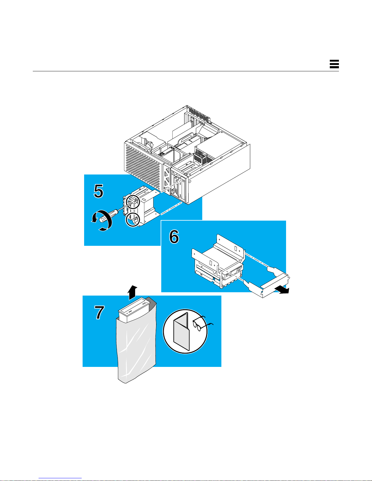
5
Installing the Hard Disk Drive
5. Open the drive handle and slide the drive completely into the
drive bay. Press the drive to connect it to the SCSI port in the
system.
6. Close the drive handle. The handle will not latch if the drive is
not properly attached or closed.
7. Detach the wrist strap and close the system unit ( 9).
Installazione dell’unità a disco fisso
5. Apr ire il vano del disco fisso e inserirlo completamente nel
telaio. Premere l’unità per collegarla alla porta SCSI del
sistema.
6. Chiudere il vano dell’unità. Se l’unità non è installata
correttamente, la manopola di chiusura non scatta in posizione
7. Togliere il cinturino antistatico e chiudere l’unità centrale ( 9).
Instalación de la unidad de disco duro
5. Abra la palanca de la unidad y deslice completamente la unidad
en su alojamiento. Presione la unidad para conectarla al puerto
SCSI del sistema.
6. Cierre la palanca de la unidad. Si ésta no está instalada
correctamente, la palanca no se bloqueará.
7. Despegue la muñequera antiestática y cierre la unidad del
sistema ( 9).
26
Page 29

5
27
Page 30

6
Installing the Diskette Drive or Accessory Device
1. Power off the system and open the system unit ( 2).
2. Locate the wrist strap, and attach its adhesive copper str ip to
the chassis back panel. Wrap the other end twice around your
wrist, with the adhesive side against your skin.
3. Remove the drive bezel from the front of the system unit.
4. Use a Phillips screwdriver to loosen the two screws holding the
drive bracket to the system.
5. Push the power cable away from the drive bracket. Lift the drive
bracket out of the system.
Installation du lecteur de disquette ou d’un périphérique connexe
1. Mettez votre système hors tension, puis ouvrez l’unité système
(reportez-vous à la procédure ( 2).
2. Attachez le bracelet de mise à la terre à votre poignet et reliez
l’extrémité adhésive en cuivre au panneau arrière du châssis.
Enroulez deux fois l’autre extrémité autour de votre poignet, la
partie adhésive de la bande côté peau.
3. Otez l’encadrement du lecteur de l’avant de l’unité système.
4. Utilisez un tournevis cruciforme pour desserer les deux vis
fixant le support au système.
5. Détachez le câble d’alimentation du support, puis tirez le support
hors du système.
Installazione dell’unità a dischetti o di un dispositivo accessorio
1. Spegnere il sistema e aprire l’unità centrale ( 2).
2. Indossare il cinturino antistatico e collegare l’estremità adesiva
in rame al pannello posteriore. Arrotolare due volte intorno al
polso l’altra estremità con la parte adesiva a contatto con la
pelle.
3. Rimuovere la lunetta frontale dall’unità centrale.
4. Per rimuovere le due viti che fissano il supporto dell’unità al
sistema, servirsi di un cacciavite a croce.
5. Estrarre il cavo di alimentazione dal supporto dell’unità e
sollevare il supporto per estrarlo.
Instalación de la unidad de disquetes o dispositivo accesorio
1. Apague el equipo y abra la unidad del sistema ( 2).
2. Ponga la muñequera antiestática con la banda adhesiva de
cobre en el panel posterior del bastidor. Envuelva el otro
extremo dos veces alrededor de la muñeca, con la parte
adhesiva contra la piel.
3. Extraiga el panel de relleno de la parte frontal de la unidad del
sistema.
28
4. Utilice un destornillador en estrella para aflojar los dos tornillos
que sujetan el soporte de la unidad al sistema.
5. Aparte el cable de alimentación del soporte de la unidad. Quite
el soporte de la unidad del sistema.
Page 31

6
29
Page 32

6
Installing the Diskette Drive or Accessory Device
6. Remove the metal filler panel from the drive bracket.
7. Remove the diskette drive or accessory device from the
antistatic bag. Read the diskette drive or accessory device
product guide for information about jumper switch settings, or
any other installation tasks.
8. Use a Phillips screwdriver to attach the diskette drive or
accessory device to the bracket using the four screws provided.
Installation du lecteur de disquette ou d’un périphérique connexe
6. Otez le cache SBus métallique du support.
7. Sortez le lecteur de disquette ou le périphérique connexe de
son emballage antistatique. Reportez-vous au guide fourni avec
le lecteur ou le périphérique connexe pour plus d’informations
sur les cavaliers et les commutateurs, ou sur les différentes
étapes de l’installation
8. A l’aide d’un tournevis cruciforme, vissez le lecteur de disquette
ou le périphérique connexe sur le support à l’aide des quatre vis
fournies à cet effet.
Installazione dell’unità a dischetti o di un dispositivo accessorio
6. Rimuovere il pannello di riempimento metallico dal supporto.
7. Estrarre l’unità a dischetti dalla confezione antistatica e leggere
le istruzioni riportate nel manuale utente dell’unità a dischetti
per informazioni relative alle impostazioni degli switch o dei
ponticelli o per le procedure di installazione.
8. Con un cacciavite a croce collegare l’unità a dischetti o il
dispositivo accessorio al supporto con le quattro viti in
dotazione.
Instalación de la unidad de disquetes o dispositivo accesorio
6. Extraiga el panel de relleno metálico del soporte de la unidad.
7. Saque la unidad de disquetes o el dispositivo accesor io de la
bolsa antiestática. Lea la guía del producto de la unidad de
disquetes o dispositivo accesor io para obtener información
sobre los valores de configuración de los puentes o
conmutadores y otras tareas de instalación.
30
8. Utilice un destornillador en estrella para fijar la unidad de
disquetes o el dispositivo accesorio al soporte de la unidad con
los cuatro tor nillos suministrados.
Page 33

6
31
Page 34

6
Installing the Diskette Drive or Accessory Device
Note — Steps 9 and 10 only apply to a diskette dr ive. If you are
installing an accessory device, see its product guide for specific
installation instructions.
9. Remove the diskette data cable from the kit and connect one
end into the drive backplane marked FLOPPY. Connect the
other end to the diskette drive.
10. Attach the connector labeled P2 to the drive.
11. Lower the drive or device into the chassis. Tighten the two
screws holding the drive bracket to the system.
12. Replace the drive bezel on the front of the system.
13. Detach the wrist strap and close the system unit ( 9).
Installation du lecteur de disquette ou d’un périphérique connexe
Remarque : les étapes 9 et 10 s’appliquent uniquement au lecteur
de disquette. Si vous installez un périphérique connexe, reportezvous au guide fourni avec celui-ci pour obtenir des informations
spécifiques sur son installation.
9. Sortez du kit le câble de données de la disquette et connectez
l’une de ses extrémités dans le panneau arrière de l’unité
portant l’inscr iption FLOPPY. Connectez l’autre extrémité au
lecteur de disquette.
10. Reliez le connecteur étiqueté P2 au lecteur.
11. Placez le lecteur ou le périphérique dans le châssis. Serrez les
deux vis fixant le support au système.
12. Replacez l’encadrement du lecteur à l’avant du système.
13. Détachez le bracelet de mise à la terre et refermez l’unité
système ( 9).
Installazione dell’unità a dischetti o di un dispositivo accessorio
Nota — I punti 9 e 10 sono validi solo per l’unità a dischetti. Se si
installa un dispositivo accessorio, consultare il relativo manuale per
le procedure d’installazione.
9. Estrarre il cavo dei dati del dischetto dal kit e collegarne
un’estremità al pannello posteriore dell’unità con la dicitura
FLOPPY. Collegare l’altra estremità all’unità a dischetti.
10. Collegare il connettore con la dicitura P2 all’unità.
11. Abbassare l’unità o il dispositivo nel telaio. Str ingere le due viti
di fissaggio del supporto dell’unità al sistema.
12. Reinserire la lunetta frontale nell’unità.
13. Togliere il cinturino antistatico e chiudere l’unità centrale ( 9).
Instalación de la unidad de disquetes o dispositivo accesorio
Nota — Los pasos 9 y 10 sólo se aplican a la unidad de disquetes.
Si está usando un dispositivo accesorio, lea la guía de producto
correspondiente para obtener instrucciones de instalación.
9. Extraiga del kit el cable de datos de la unidad y conecte un
extremo a la placa de unidad marcada como FLOPPY. Conecte
el otro extremo a la unidad de disquetes.
32
10. Conete a la unidad el conector etiquetado P2.
11. Fije la unidad o dispositivo en el bastidor, apretando los dos
tornillos que sujetan el soporte de la unidad al sistema.
12. Vuelva a colocar el panel de relleno de la parte frontal del
sistema.
13. Despegue la muñequera antiestática y cierre la unidad del
sistema ( 9).
Page 35

6
33
Page 36

7
Installing the CD-ROM Drive or Tape Drive
1. Power off the system and open the system unit ( 2).
2. Locate the wrist strap, and attach its adhesive copper str ip to
the chassis back panel. Wrap the other end twice around your
wrist, with the adhesive side against your skin.
3. Remove the drive bezel from the front of the system unit.
4. Use a Phillips screwdriver to loosen the two screws holding the
drive bracket to the system.
Installation du lecteur de CD-ROM ou du lecteur de bande
1. Mettez votre système hors tension, puis ouvrez l’unité système
(reportez-vous à la procédure ( 2)
2. Attachez le bracelet de mise à la terre à votre poignet et reliez
l’extrémité adhésive en cuivre au panneau arrière du châssis.
Enroulez deux fois l’autre extrémité autour de votre poignet, la
partie adhésive de la bande côté peau.
3. Otez l’encadrement du lecteur de l’avant de l’unité système.
4. A l’aide d’un tournevis cr uciforme, desserrez les deux vis fixant
le support au système.
Installazione dell’unità CD-ROM o dell’unità a nastro
1. Spegnere il sistema e aprire l’unità centrale ( 2).
2. Indossare il cinturino antistatico e collegare l’estremità adesiva
in rame al pannello posteriore. Arrotolare due volte intorno al
polso l’altra estremità con la parte adesiva a contatto con la
pelle.
3. Estrarre la lunetta frontale dall’unità centrale.
4. Con un cacciavite a croce, allentare le due viti che fissano il
supporto dell’unità al sistema.
Instalación de la unidad de CD-ROM o de cinta
1. Apague el equipo y abra la unidad del sistema ( 2).
2. Localice la muñequera antiestática y coloque la banda adhesiva
de cobre en el panel posterior del bastidor. Envuelva el otro
extremo dos veces alrededor de la muñeca, con la parte
adhesiva contra la piel.
34
3. Extraiga el panel de relleno de la parte frontal de la unidad del
sistema.
4. Utilice un destornillador en estrella para aflojar los dos tornillos
que sujetan el soporte de la unidad al sistema.
Page 37

7
35
Page 38

7
Installing the CD-ROM Drive or Tape Drive
5. Push the power cable away from the drive bracket. Lift the drive
bracket out of the system.
6. Remove the metal filler panel from the drive bracket.
7. Remove the drive from the antistatic bag. Read the drive
product guide for information about jumper switch settings or
any other installation tasks.
Note — SCSI address 6 must be assigned to the internal CD-ROM
drive. SCSI address 4 or 5 is customarily assigned to the internal
tape drive. Make sure external SCSI devices connected to the
onboard SCSI connector do not use the same addresses used for
internal SCSI devices.
Installation du lecteur de CD-ROM ou du lecteur de bande
5. Détachez le câble d’alimentation du support, puis tirez le
support hors du système.
6. Otez le SBus métallique du spport.
7. Sortez le lecteur de son emballage antistatique. Reportez-vous
au guide fourni avec le lecteur pour plus d’informations sur les
cavaliers et les commutateurs, ou sur les différentes étapes de
l’installation.
Remarque : l’adresse SCSI 6 doit être attribuée au lecteur de CDROM interne. L’adresse SCSI 4 ou 5 est habituellement attribuée au
lecteur de bande interne. Vérifiez que les périphériques SCSI
externes reliés au connecteur SCSI sur carte n’utilisent pas les
mêmes adresses que les périphériques SCSI internes.
Installazione dell’unità CD-ROM o dell’unità a nastro
5. Estrarre il cavo di alimentazione dal supporto dell’unità e
sollevare il supporto per estrarlo.
6. Rimuovere il pannello di riempimento metallico dal supporto.
7. Estrarre l’unità dalla confezione antistatica e leggere le
istruzioni riportate nel manuale utente dell’unità CD-ROM per
informazioni relative alle impostazioni degli switch o dei
ponticelli o per le procedure di installazione
Nota — Assegnare l’indirizzo 6 SCSI all’unità CD-ROM interna. Di
solito l’indirizzo 4 o 5 SCSI vengono assegnati all’unità a nastro
interna. Accertarsi che i dispositivi SCSI esterni collegati al
connettore SCSI integrato non utilizzino gli stessi indirizzi dei
dispositivi interni.
Instalación de la unidad de CD-ROM o de cinta
5. Aparte el cable de alimentación del soporte de la unidad. Quite
el soporte de la unidad del sistema.
6. Extraiga el panel de relleno metálico del soporte de la unidad.
7. Saque la unidad de la bolsa antiestática. Lea la guía del
producto de la unidad para obtener información sobre los
valores de configuración de puentes o conmutadores y otras
tareas de instalación.
36
Nota — La dirección SCSI 6 debe asignarse a la unidad de CDROM interna. Las direcciones SCSI 4 o 5 se asignan normalmente
a la unidad de cinta interna. Asegúrese de que los dispositivos
SCSI externos conectados al interfaz SCSI interno no usan las
mismas direcciones que los dispositivos SCSI internos.
Page 39
7
37
Page 40

7
Installing the CD-ROM Drive or Tape Drive
8. Use a Phillips screwdriver to attach the drive to the bracket
using the four screws provided.
9. Partially lower the bracket into the chassis and attach the cables
to the drive:
• CD-ROM drive: connectors labeled CD and P3
• Tape drive: power cable and data cable
10. Complete lowering the drive bracket into the chassis. Tighten
the two screws holding the drive bracket to the system.
11. Replace the drive bezel on the front of the system.
12. Detach the wrist strap and close the system unit ( 9).
Installation du lecteur de CD-ROM ou du lecteur de bande
8. A l’aide d’un tournevis cruciforme, vissez le lecteur sur le
support à l’aide des quatre vis fournies à cet effet.
9. Insérez partiellement le support dans le châssis et reliez les
câbles au lecteur :
• Lecteur de CD-ROM : connecteurs étiquetés CD et P3.
• Lecteur de bande : câble d’alimentation et câble de données.
10. Insérez complètement le suppor t dans le châssis. Serrez les
deux vis fixant le support au système.
11. Replacez l’encadrement du lecteur à l’avant du système.
12. Détachez le bracelet de mise à la terre et refermez l’unité
système ( 9)
Installazione dell’unità CD-ROM o dell’unità a nastro
8. Con un cacciavite a croce, collegare l’unità al supporto
utilizzando le quattro viti in dotazione.
9. Abbassare parzialmente il suppor to nel telaio e collegare i cavi
all’unità:
• Unità CD-ROM: connettori con dicitura CD e P3
• Unità a nastro: cavo di alimentazione e cavo dei dati
10. Abbassare completamente il supporto dell’unità nel telaio.
Stringere le quattro viti di fissaggio del supporto dell’unità al
sistema.
11. Rimettere la lunetta frontale nell’unità centrale.
12. Togliere il cinturino antistatico e chiudere l’unità centrale ( 9).
Instalación de la unidad de CD-ROM o de cinta
8. Utilice un destornillador en estrella para fijar la unidad al
soporte con los cuatro tornillos suministrados.
9. Acerque el soporte al bastidor y conecte los cables a la unidad:
• Unidad de CD-ROM: conectores CD y P3
• Unidad de cinta: cable de alimentación y de datos
38
10. Fije el soporte de la unidad en el bastidor, apretando los dos
tornillos que sujetan el soporte de la unidad al sistema.
11. Vuelva a colocar el panel de relleno de la parte frontal del
sistema.
12. Despegue la muñequera antiestática y cierre la unidad del
sistema ( 9).
Page 41

7
39
Page 42

8
Installing UPA Graphics Cards or PCI Cards
Note — If you are installing a PCI card, first see ( 12).
1. Power off the system and open the system unit ( 2).
2. Locate the wrist strap, and attach its adhesive copper str ip to
the chassis back panel. Wrap the other end twice around your
wrist, with the adhesive side against your skin.
3. Remove the filler panel from the back panel of the system
chassis.
4. Fit the card back panel into one of the system chassis card
slots, and lower the card connector so that it touches its
associated card slot on the main logic board.
Installation de cartes graphiques UPA ou de cartes PCI
Remarque : si vous installez une carte PCI, consultez au préalable
la procédure 12.
1. Mettez votre système hors tension et ouvrez l’unité système (
2).
2. Attachez le bracelet de mise à la terre à votre poignet et reliez
son extrémité adhésive en cuivre au panneau arrière du
châssis. Enroulez deux fois l’autre extrémité autour de votre
poignet, la partie adhésive de la bande côté peau.
3. Otez le cache SBus du panneau arr ière du châssis du système.
4. Engagez le panneau arrière de la car te dans l’un des
emplacements de carte du châssis du système et insérez le
connecteur de carte dans l’emplacement qui lui est associé sur
la carte système.
Installazione delle schede grafiche UPA o delle schede PCI
Nota — Se si installa una scheda PCI, consultare prima ( 12).
1. Spegnere il sistema e aprire l’unità centrale ( 2).
2. Indossare il cinturino antistatico e collegare l’estremità adesiva
in rame al pannello posteriore. Arrotolare due volte intorno al
polso l’altra estremità con la parte adesiva a contatto con la
pelle.
3. Rimuovere il pannello di riempimento dal pannello posteriore
del telaio.
4. Inser ire il pannello posteriore della scheda in uno degli slot del
telaio e abbassare il connettore in modo che tocchi il relativo
slot per la scheda sulla scheda madre.
Instalación de tarjetas de gráficos UPA o tarjetas PCI
Nota — SI está instalando una tarjeta PCI, consulte antes ( 12).
1. Apague el equipo y abra la unidad del sistema ( 2).
2. Localice la muñequera antiestática y coloque la banda adhesiva
de cobre en el panel posterior del bastidor. Envuelva el otro
extremo dos veces alrededor de la muñeca, con la parte
adhesiva contra la piel.
40
3. Extraiga el panel de relleno situado en el panel posterior del
bastidor del sistema.
4. Encaje el panel posterior de la tarjeta en una de las ranuras
para tarjetas del bastidor del sistema y baje el conector de la
tarjeta para que contacte con su ranura de tarjeta asociada de
la placa lógica principal.
Page 43

8
41
Page 44

8
Installing UPA Graphics Cards or PCI Cards
5. Push the card by its corners straight down into the slot until the
card is fully seated.
6. Use a magnetized Phillips screwdriver to attach the card bracket
tab to the system chassis.
7. Detach the wrist strap and close the system unit ( 9).
Installation de cartes graphiques UPA ou de cartes PCI
5. Appuyez sur les coins de la carte pour l’enfoncer dans son
emplacement jusqu’à ce qu’elle soit enclenchée.
6. A l’aide d’un tournevis cruciforme aimanté, reliez la languette du
support de la carte au châssis du système.
7. Retirez le bracelet de mise à la terre et fermez l’unité système
( 9).
Installazione delle schede grafiche UPA o delle schede PCI
5. Spingere la scheda nello slot tenendola dagli angoli finché non
si fissa completamente.
6. Con un cacciavite a croce magnetizzato, collegare la tacca del
supporto della scheda al telaio.
7. Togliere il cinturino antistatico e chiudere l’unità centrale ( 9).
Instalación de tarjetas de gráficos UPA o tarjetas PCI
5. Presione la tarjeta por los bordes contra la ranura hasta que
quede completamente fija.
6. Use un destornillador en estrella magnetizado para fijar la
pestaña de soporte de la tarjeta al bastidor del sistema.
7. Despegue la muñequera antiestática y cierre la unidad del
sistema ( 9).
42
Page 45

8
43
Page 46

9
Closing the System Unit
1. Holding the side panel in both hands, guide it so that the hooks
align with the channels on the system unit chassis.
2. Install the lock block if necessar y.
Fermeture de l’unité système
1. Tenez des deux mains le panneau latéral, guidez-le de telle
sorte que les crochets s’alignent sur les rainures du châssis de
l’unité système.
2. Réinstallez si nécessaire le système de verrouillage.
Chiusura dell’unità centrale
1. Tenendo il pannello laterale da entrambi i lati, guidarlo in modo
che i ganci siano allineati ai canali del telaio.
2. Se necessario, installare l’antifurto.
Cierre de la unidad del sistema
1. Sujetando el panel lateral con las dos manos, alinee sus
ganchos con las guías del bastidor de la unidad del sistema.
2. Instale el elemento de bloqueo si fuera necesario.
44
Page 47

9
45
Page 48

10
DIMM Installation Guidelines
• Dual inline memory modules (DIMMs) are installed in pairs.
• Each pair must be of the same memory size and speed.
• To boot, the system must have one DIMM pair in mapped slots.
• DIMMs are mapped in banks of four DIMMs.
• For best system peformance, install each bank with four DIMMs.
• Keep DIMMs in each bank identical in memory size and speed.
• DIMM sizes of 16-, 32-, 64-, and 128-Megabytes are supported.
Note — See ( 11) for additional DIMM installation information.
Instructions d’installation des modules DIMM
• Les modules DIMM sont installés par paires.
• Chaque paire doit avoir une taille de mémoire et une vitesse
identiques.
• Pour s’initialiser, le système doit comporter une paire de modules
DIMM dans des emplacements mis en correspondance.
• Les modules DIMM sont mis en correspondance dans des
rangées de quatre DIMM.
• Pour optimiser les performances du système, installez quatre
• Les modules DIMM de chaque rangée doivent avoir la même taille
• Les modules DIMM peuvent avoir une taille de mémoire de 16, 32,
Remarque : repor tez-vous à la procédure 11 pour plus
d’informations sur l’installation des modules DIMM.
Instruzioni d’installazione del DIMM
• I moduli di memoria in linea doppi (DIMM) vanno installati a
coppie.
• Ogni coppia deve avere dimensioni e velocità di memoria
identiche.
• Per avviare il sistema, occorre che una coppia di DIMM sia stata
installata negli slot mappati.
• I DIMM sono mappati in serie di quattro DIMM.
• Per ottenere prestazioni ottimali, installare quattro DIMM per serie.
• I DIMM della stessa serie devono avere dimensioni e velocità di
• Sono supportai i DIMM di 16, 32, 64 e 128 Megabyte.
Nota — Per informazioni aggiuntive sull’installazione dei DIMM,
consultare ( 11).
modules DIMM dans chaque rangée.
de mémoire et la même vitesse.
64 et 128 méga-octets.
memoria identiche.
Directrices para la instalación de DIMM
• Instale los módulos de memoria dual en línea (DIMM) a pares.
• Cada par de módulos de memoria debe tener la misma
capacidad y velocidad.
• Para que el sistema arranque debe tener un par de DIMM en
ranuras reasignadas.
• Los DIMM se reasignan en bancos de cuatro DIMM.
• Para obtener el mejor rendimiento del sistema, instale cuatro
46
DIMM en todos los bancos.
• La velocidad y capacidad de los DIMM de los bancos han de ser
idénticas.
• Se admiten DIMM de una capacidad de 16, 32, 64 y 128 Mb.
Nota — Consulte ( 11) para más información sobre la
instalación.
Page 49

10
47
Page 50

11
DIMM Banks and Slot Pairs
Bank: Slot Pairs:
0 U0701 + U0801
0 U0901 + U1001
1 U0702 + U0802
1 U0902 + U1002
Bank: Slot Pairs:
2 U0703 + U0803
2 U0903 + U1003
3 U0704 + U0804
3 U0904 + U1004
Rangées et paires d’emplacements de modules DIMM
Rangée : Paires d’emplacements :
0 U0701 + U0801
0 U0901 + U1001
1 U0702 + U0802
1 U0902 + U1002
Rangée : Paires d’emplacements :
2 U0703 + U0803
2 U0903 + U1003
3 U0704 + U0804
3 U0904 + U1004
Serie di DIMM e coppie di slot
Serie: Coppie di slot:
0 U0701 + U0801
0 U0901 + U1001
1 U0702 + U0802
1 U0902 + U1002
Serie: Coppie di slot:
2 U0703 + U0803
2 U0903 + U1003
3 U0704 + U0804
3 U0904 + U1004
Bancos de DIMM y pares de ranuras
Banco: Pares de ranuras:
0 U0701 + U0801
0 U0901 + U1001
1 U0702 + U0802
1 U0902 + U1002
48
Banco: Pares de ranuras:
2 U0703 + U0803
2 U0903 + U1003
3 U0704 + U0804
3 U0904 + U1004
Page 51

11
U1004
3
2
1
0
U0904
U0804
U0704
U1003
U0903
U0803
U0703
U1002
U0902
U0802
U0702
U1001
U0901
U0801
U0701
49
Page 52

12
PCI Card Slot Operating Frequencies
• All Sun Ultra 30 system PCI card slots operate at 32-bit or
PCI Operating Input/Output
Card Slot: Frequency: Signaling Level:
Slot 1 J1301 33 MHz or 66 MHz 3.3 volts
Slot 2 J1401 33 MHz 5.0 volts
Slot 3 J1501 33 MHz 5.0 volts
Slot 4 J1601 33 MHz 5.0 volts
Fréquences de fonctionnement des emplacements de car tes PCI
Carte d’empla- Fréquence de Niveau de signalicement PCI : fonctionnement : sation entrée/sortie :
Slot 1 J1301 33 MHz ou 66 MHz 3,3 volts
Slot 2 J1401 33 MHz 5,0 volts
Slot 3 J1501 33 MHz 5,0 volts
Slot 4 J1601 33 MHz 5,0 volts
Frequenze operative degli slot della scheda PCI
Slot Frequenza Livello di segnale
scheda PCI: operativa: Input/Output:
Slot 1 J1301 33 MHz o 66 MHz 3,3 volt
Slot 2 J1401 33 MHz 5,0 volt
Slot 3 J1501 33 MHz 5,0 volt
Slot 4 J1601 33 MHz 5,0 volt
64-bit bus widths.
• Most PCI cards operate at 33 MHz.
• Cards designed to operate at 66 MHz must be installed in
PCI card slot 1.
• Tous les emplacements de cartes PCI du système Sun Ultra 30
fonctionnent à des largeurs de bus de données 32 ou 64 bits.
• La plupart des cartes PCI fonctionnent à 33 MHz.
• Les cartes conçues pour fonctionner à 66 MHz doivent être
installées dans l’emplacement de carte PCI 1.
• Tutti gli slot delle schede PCI per i sistemi Sun Ultra 30 operano
ad ampiezze di bus a 32 o 64 bit.
• La maggior parte delle schede PCI funzionano a 33 MHz.
• Le schede progettate per un funzionamento a 66 MHz devono
essere installate nello slot della scheda 1.
Frecuencias de funcionamiento de ranuras de tarjetas PCI
Ranura tarjeta Frecuencia de Nivel señalización
PCI: funcionamiento: Entrada/Salida:
Ranura 1 J1301 33 MHz o 66 MHz 3.3 voltios
Ranura 2 J1401 33 MHz 5 voltios
Ranura 3 J1501 33 MHz 5 voltios
Ranura 4 J1601 33 MHz 5 voltios
50
• Todas las ranuras de tarjetas PCI de los sistemas Sun Ultra 30
funcionan con anchos de bus de 32 o 64 bits.
• La mayoría de tarjetas PCI funcionan a 33 MHz.
• Las tarjetas diseñadas para funcionar a 66 MHz deben instalarse
en la ranura PCI 1.
Page 53

J1301
J1401
12
J1501
J1601
51
Page 54

13
What’s Next
After you have installed all inter nal options and made modifications
to the system, you are ready to have a system administrator install
the Solar is software. Refer to the
Guide
.
After the software is installed (including the
Hardware AnswerBook
AnswerBook.
), install the
SMCC SPARC Hardware Platform
Solaris on Sun
Sun Ultra 30 Hardware
Informations supplémentaires
Une fois que vous avez installé toutes les options internes et
apporté les modifications nécessaires au système, le logiciel Solaris
peut être installé par un administrateur système. Reportez-vous au
Guide de la plate-forme matérielle SPARC SMCC
Une fois le logiciel installé (y compris
AnswerBook
), installlez
Sun Ultra 30 Hardware AnswerBook.
Solaris on Sun Hardware
.
Operazioni successive
Dopo avere installato tutte le opzioni interne ed effettuato tutte le
modifiche sul sistema, si può chiedere all’amministratore del
sistema di installare il software Solaris. Consultare la
piattaforme hardware SPARC SMCC
Dopo avere installato il software (compreso
Hardware AnswerBook
AnswerBook.
), installare
.
Solaris on Sun
Sun Ultra 30 Hardware
Guida alle
For more information, refer to:
Sun Ultra 30 Hardware Setup Instructions
Sun Ultra 30 Product Notes
Sun Ultra 30 Hardware AnswerBook Installation
SMCC SPARC Hardware Platform Guide
Solaris Handbook for SMCC Peripherals
Pour de plus amples informations, consultez la documentation
ci-après :
Sun Ultra 30 Hardware Setup Instructions
Sun Ultra 30 Product Notes
Sun Ultra 30 Hardware AnswerBook Installation
Guide de la plate-forme matérielle SPARC SMCC
Solaris Handbook for SMCC Peripherals
Per maggior i informazioni, consultare:
Sun Ultra 30 Hardware Setup Instructions
Sun Ultra 30 Product Notes
Sun Ultra 30 Hardware AnswerBook Installation
Guida alle piattaforme hardware SPARC SMCC
Solaris Handbook for SMCC Peripherals
Qué hacer a continuación
Cuando haya instalado todas las opciones internas y realizado las
modificaciones en el sistema, estará listo para que un administrador
del sistema instale el software de Solar is. Consulte el manual
para plataformas de hardware SPARC de SMCC
Una vez instalado el software (incluyendo
AnswerBook
52
), instale
Sun Ultra 30 Hardware AnswerBook
Guía
.
Solaris on Sun Hardware
.
Para más información, consulte:
Sun Ultra 30 Hardware Setup Instructions
Sun Ultra 30 Product Notes
Sun Ultra 30 Hardware AnswerBook Installation
Guía para plataformas de hardware SPARC de SMCC
Solaris Handbook for SMCC Peripherals
Page 55

13
53
Page 56

Safety Ag ency Compliance
The following text provides safety precautions to follow when
installing a Sun Microsystems, Inc. product.
Safety Precautions
For your protection, observe the following safety precautions when
setting up your equipment:
• Follow all warnings and instructions marked on the equipment.
• Ensure that the voltage and frequency of your power source match
the voltage and frequency inscribed on the equipment’s electrical
rating label.
• Never push objects of any kind through openings in the
equipment. Dangerous voltages may be present. Conductive
foreign objects could produce a short circuit that could cause fire,
electric shock, or damage to your equipment.
Symbols
The following symbols appear in this book:
Caution – There is risk of personal injury and equipment
damage. Follow the instructions.
!
Caution – Hot surface. Avoid contact. Surfaces are hot and
may cause personal injury if touched.
Warning – Hazardous voltages are present. To reduce the
risk of electric shock and danger to personal health, follow
the instructions.
Modifications to Equipment
Do not make mechanical or electrical modifications to the
equipment. Sun Microsystems, Inc. is not responsible for regulatory
compliance of a modified Sun product.
Placement of a Sun Product
Caution – To ensure reliable operation of your Sun product
and to protect it from overheating, openings in the
!
equipment must not be blocked or covered. A Sun product
should never be placed near a radiator or heat register.
European Ergonomics
In order to conform with the German ZH1/618 ergonomic standard,
an antiglare treatment to the CRT has been provided. For text
processing applications, a positive mode display (black characters
on a white background) is required.
SELV Compliance
Safety status of I/O connections comply with SELV requirements.
Power Cord Connection
Warning – Sun products are designed to work with
single-phase power systems having a grounded neutral
conductor. To reduce the risk of electric shock, do not plug
Sun products into any other type of power system. Contact
your facilities manager or a qualified electrician if you are
not sure what type of power is supplied to your building.
Warning – Not all power cords have the same current
ratings. Household extension cords do not have overload
protection and are not meant for use with computer systems.
Do not use household extension cords with your Sun
product.
Warning – Your Sun product is shipped with a grounding
type (three-wire) power cord. To reduce the risk of electric
shock, always plug the cord into a grounded power outlet.
Warning – The power switch of this product functions as a
standby type device only. The power cord serves as the
primary disconnect device for the system. Be sure to plug
the power cord into a grounded power outlet that is nearby
the system and is readily accessible. Do not connect the
power cord when the power supply has been removed from
the system chassis.
Lithium Battery
Caution – On Sun CPU boards, there is a lithium battery
molded into the real-time clock, SDS No. MK48T59Y,
!
MK48TXXB-XX, MK48T18-XXXPCZ, or
M48T59W-XXXPCZ. Batteries are not customer replaceable
parts. They may explode if mistreated.Do not dispose of the
battery in fire. Do not disassemble it or attempt to recharge
it.
System Unit Cover
You must remove the cover of your Sun computer system unit in
order to add cards, memory, or internal storage devices. Be sure to
replace the top cover before powering up your computer system.
Caution – It is not safe to operate Sun products without the
top cover in place. Failure to take this precaution may result
!
in personal injury and system damage.
54
Page 57

Conformité aux normes de sécurité
Ce texte traite des mesures de sécurité qu’il convient de prendre
pour l’installation d’un produit Sun Microsystems, Inc.
Mesures de sécurité
Pour votre protection, veuillez prendre les précautions suivantes
pendant l’installation du matériel :
• Suivre tous les avertissements et toutes les instructions inscr ites
sur le matériel.
• Vérifier que la tension et la fréquence de la source d’alimentation
électrique correspondent à la tension et à la fréquence indiquées
sur l’étiquette de classification de l’appareil.
• Ne jamais introduire d’objets quels qu’ils soient dans une des
ouvertures de l’appareil. Vous pourriez vous trouver en présence
de hautes tensions dangereuses. Tout objet conducteur introduit
de la sorte pourrait produire un court-circuit qui entraînerait des
flammes, des risques d’électrocution ou des dégâts matériels.
Symboles
Vous trouverez ci-dessous la signification des différents symboles
utilisés :
Attention : risques de blessures corporelles et de dégâts
matériels. Veuillez suivre les instructions.
!
Attention : surface à température élevée. Evitez le contact.
La température des surfaces est élevée et leur contact peut
provoquer des blessures corporelles.
Danger : présence de tensions dangereuses. Pour éviter les
risques d’électrocution et de danger pour la santé physique,
veuillez suivre les instr uctions.
Modification du matériel
Ne pas apporter de modification mécanique ou électrique au
matériel. Sun Microsystems, Inc. n’est pas responsable de la
conformité réglementaire d’un produit Sun qui a été modifié.
Positionnement d’un produit Sun
Attention : pour assurer le bon fonctionnement de votre
produit Sun et pour l’empêcher de surchauffer, il convient de
!
ne pas obstruer ni recouvrir les ouvertures prévues dans
l’appareil. Un produit Sun ne doit jamais être placé à
proximité d’un radiateur ou d’une source de chaleur.
Ergonomie européenne
Conformément à la norme d’ergonomie allemande ZH1/618, le CRT
a été soumis à un traitement antireflets. Pour le traitement de texte,
un affichage en mode positif (c’est-à-dire des caractères noirs sur
fond blanc) est nécessaire.
Conformité SELV
Sécurité : les raccordements E/S sont conformes aux normes SELV.
Connexion du cordon d’alimentation
Danger : les produits Sun sont conçus pour fonctionner
avec des alimentations monophasées munies d’un
conducteur neutre mis à la terre. Pour écar ter les risques
d’électrocution, ne pas brancher de produit Sun dans un
autre type d’alimentation secteur. En cas de doute quant au
type d’alimentation électrique du local, veuillez vous
adresser au directeur de l’exploitation ou à un électricien
qualifié.
Danger : tous les cordons d’alimentation n’ont pas
forcément la même puissance nominale en matière de
courant. Les rallonges d’usage domestique n’offrent pas de
protection contre les surcharges et ne sont pas prévues
pour les systèmes d’ordinateurs. Ne pas utiliser de rallonge
d’usage domestique avec votre produit Sun.
Danger : votre produit Sun a été livré équipé d’un cordon
d’alimentation à trois fils (avec prise de terre). Pour écarter
tout risque d’électrocution, branchez toujours ce cordon
dans une prise mise à la terre.
Danger : le commutateur d’alimentation de ce produit
fonctionne comme un dispositif de mise en veille
uniquement. C’est la prise d’alimentation qui sert à mettre le
produit hors tension. Veillez donc à installer le produit à
proximité d’une prise murale facilement accessible. Ne
connectez pas la prise d’alimentation lorsque le châssis du
système n’est plus alimenté.
Batterie au lithium
Attention : sur les cartes CPU Sun, une batter ie au lithium
(référence MK48T59Y, MK48TXXB-XX, MK48T18-XXXPCZ
!
ou M48T59W-XXXPCZ) a été moulée dans l’horloge temps
réel SGS. Les batteries ne sont pas des pièces
remplaçables par le client. Elles risquent d’exploser en cas
de mauvais traitement. Ne pas jeter la batter ie au feu. Ne
pas la démonter ni tenter de la recharger.
Couvercle
Pour ajouter des cartes, de la mémoire, ou des unités de stockage
internes, vous devrez démonter le couvercle de l’unité système
Sun. Ne pas oublier de remettre ce couvercle en place avant de
mettre le système sous tension.
Attention : il est dangereux de faire fonctionner un produit
Sun sans le couvercle en place. Si l’on néglige cette
!
précaution, on encourt des risques de blessures corporelles
et de dégâts matériels.
55
Page 58
Conformità alle norme di sicurezza
Il testo che segue riporta le norme di sicurezza da seguire
nell’installazione dei prodotti Sun Microsystems, Inc.
Norme di sicurezza
Per la propria sicurezza, osservare le seguenti norme nell’installare
il materiale.
• Rispettare tutte le avvertenze e le istruzioni indicate.
• Accer tarsi che la tensione e la frequenza dell’alimentazione di rete
in uso siano adatte a quelle indicate sulle etichette delle
caratteristiche elettriche del materiale.
• Non introdurre oggetti di nessun tipo nelle eventuali fessure,
poiché potrebbero essere presenti tensioni pericolose. Oggetti
estranei potrebbero produrre cortocircuito, con rischio di incendio,
scossa elettrica e danni al sistema.
Simboli
In questo manuale appaiono i seguenti simboli:
Attenzione - Indica un rischio di danni fisici e mater iali.
Seguire le istruzioni.
!
Attenzione - Superficie ad alta temperatura. Evitare il
contatto. Le superficie sono calde e possono causare danni
fisici in caso di contatto.
Avvertenza - Sono presenti tensioni pericolose. Per evitare
scosse elettriche e per la propria incolumità, seguire le
istruzioni.
Modifiche al prodotto
Non effettuare modifiche meccaniche o elettriche sul prodotto. Sun
Microsystems non garantisce la conformità alle nor me di prodotti
modificati.
Installazione di un prodotto Sun
Attenzione - Per garantire un corretto funzionamento del
prodotto Sun, evitare di bloccare o coprire le aperture del
!
sistema. Non porre mai un prodotto Sun vicino a radiatori o
altre fonti di calore.
Standard ergonomici europei
Lo schermo ha subito un trattamento antiriflesso per renderlo
conforme allo standard ergonomico tedesco ZH1/618. Per
applicazioni di elaborazione testi è richiesto un display a modalità
positiva (caratteri neri su fondo bianco).
Conformità alle norme SELV
Le condizioni di sicurezza delle connessioni I/O devono essere
conformi ai requisiti SELV.
Collegamento del cavo di alimentazione
Avvertenza – I prodotti Sun sono progettati per sistemi di
alimentazione monofase con un conduttore neutro collegato
a terra. Per ridurre il rischio di scosse elettriche, non
collegare i prodotti Sun ad altri sistemi di alimentazione. Se
non si è sicuri del tipo di sistema di alimentazione in uso,
rivolgersi al responsabile della manutenzione o ad un
elettricista qualificato.
Avvertenza - Non tutti i cavi di alimentazione hanno la
stessa corrente nominale. Evitare l’uso di prolunghe di tipo
domestico con i prodotti Sun in quanto non sono protette dal
sovraccarico e non ne è previsto l’uso con i computer.
Avvertenza - L’apparecchio Sun viene fornito con un cavo di
alimentazione provvisto di collegamento a terra (a 3 fili). Per
ridurre il rischio di scosse elettr iche, collegare il cavo ad una
presa a terra.
Avvertenza – L’interruttore di alimentazione del sistema
funziona solo come dispositivo di tipo stand-by. La presa di
corrente deve essere utilizzata solo come dispositivo di
sconnessione primaria. Accertarsi di collegare il cavo di
alimentazione ad una presa a terra vicina al sistema in
modo che sia di facile accesso. Non collegare il cavo di
alimentazione se l’alimentatore è stato rimosso dal sistema.
Batteria al litio
Attenzione – Sulle schede CPU Sun, è montata una
batteria al litio integrata all’RTC, SDS N. MK48T59Y,
!
MK48TXXB-XX, MK48T18-XXXPCZ, o M48T59W-XXXPCZ.
Le batter ie non sono sostituibili dall’utente e, se maneggiate
impropriamente, possono esplodere. Non gettare le batterie
nel fuoco, non smontarle, né ricaricarle.
Coperchio dell’unità centrale
Per aggiungere schede, memoria o dispositivi di memoria di massa
interni, è necessario togliere il coperchio dell’unità centrale.
Rimontare il coperchio prima di rimettere il sistema sotto tensione.
Attenzione – Non utilizzare i prodotti Sun senza il coperchio
superiore per evitare danni fisici e materiali.
!
56
Page 59

Normativas de seguridad
El siguiente texto proporciona las medidas de seguridad a seguir
cuando se instale algún producto de Sun Microsystems, Inc.
Precauciones de seguridad
Para su protección observe las siguientes medidas de seguridad
cuando manipule el equipo:
• Siga todos los avisos e instrucciones marcados en el equipo.
• Asegúrese de que el voltaje y la frecuencia de la red eléctrica
concuerdan con los descritos en las etiquetas de especificaciones
eléctricas del equipo.
• No introduzca nunca objetos de ningún tipo a través de los
orificios del equipo. Puede haber presentes voltajes peligrosos.
Los objetos extraños conductores de la electricidad pueden
producir cortocircuitos que provoquen un incendio, descargas
eléctricas o daños al equipo.
Símbolos
En este libro aparecen los siguientes símbolos:
Precaución – Existe el riesgo de lesiones personales y
daños al equipo. Siga las instrucciones.
!
Precaución – Superficie caliente. Evite el contacto. Las
superficies están calientes y pueden causar daños
personales si se tocan.
Aviso – Voltaje peligroso presente. Para reducir el riesgo de
descarga y daños para la salud siga las instrucciones.
Conexión del cable de alimentación eléctrica
Aviso – Los productos Sun están diseñados para trabajar
en una red eléctrica monofásica con toma de tierra. Para
reducir el riesgo de descarga eléctrica, no conecte los
productos Sun a otro tipo de red. Contacte con su
responsable de mantenimiento o con un electricista
cualificado si no está seguro del sistema de alimentación
eléctrica del que se dispone en su edificio.
Aviso – No todos los cables de alimentación eléctrica
tienen la misma capacidad. Los de tipo doméstico no tienen
protecciones contra sobrecargas, por ello no son adecuados
para su uso con computadores. No use alargadores de tipo
doméstico para conectar sus productos Sun.
Aviso – Sun proporciona con el producto un cable de
alimentación con toma de tierra. Para reducir el riesgo de
descargas eléctricas conéctelo siempre a un enchufe con
toma de tierra.
Aviso – El interruptor de encendido de este producto
funciona sólo como un dispositivo de puesta en espera. El
enchufe de la fuente de alimentación está diseñado para ser
el elemento primario de desconexión del equipo. Éste debe
instalarse cerca del enchufe para que éste sea de fácil y
rápido acceso. No conecte el cable de alimentación si se ha
retirado la fuente de alimentación del bastidor del sistema.
Modificaciones en el equipo
No realice modificaciones de tipo mecánico o eléctrico en el equipo.
Sun Microsystems, Inc. no se hace responsable del cumplimiento
de las nor mativas de seguridad en los equipos Sun modificados.
Colocación de un producto Sun
Precaución – Para asegurar la fiabilidad de funcionamiento
de su producto Sun y protegerlo de sobrecalentamientos no
!
deben obstr uirse o taparse las aberturas de ventilación. Los
productos Sun nunca deben situarse próximos a radiadores
o fuentes de calor.
Normativa ergonómica europea
Para cumplir con el estándar de ergonomía alemán ZH1/618, se ha
dotado a la pantalla con un tratamiento antirreflectante. Para las
aplicaciones de tratamiento de textos, se precisa un modo de
visualización positivo (carácteres negros sobre fondo blanco).
Cumplimiento de la normativa SELV
El estado de la seguridad de las conexiones de entrada/salida
cumple los requisitos de la normativa SELV.
Batería de litio
Precaución – En las placas de CPU Sun, hay una batería
de litio insertada en el reloj de tiempo real, tipo SDS núm.
!
MK48T59Y, MK48TXXB-XX, MK48T18-XXXPCZ o
M48T59W-XXXPCZ. Las baterías no son elementos
reemplazables por el propio cliente. Pueden explotar si se
manipulan de forma errónea. No arroje las baterías al fuego.
No las abra ni intente recargarlas.
Tapa de la unidad del sistema
Debe quitar la tapa del sistema cuando sea necesario añadir
tarjetas, memoria o dispositivos de almacenamiento internos. Cierre
la tapa superior antes de volver a encender el equipo.
Precaución – Es peligroso hacer funcionar los productos
Sun sin la tapa superior colocada: puede ocasionar daños
!
personales o perjudicar el funcionamiento del equipo.
57
Page 60

Caution — Attention — Attenzione — Precaución
Laser Compliance Notice
Sun products that use laser technology comply wit Class 1 laser
requirements.
Note de conformité aux produits laser
Les produits Sun faisant appel à la technologie laser sont
conformes aux nor mes laser de la classe 1.
Avviso sulla conformità laser
I prodotti Sun che utilizzano la tecnologia laser sono conformi ai
requisiti laser di Classe 1.
Normativa para tecnología láser
Los productos de Sun que emplean tecnología láser cumplen con
las normativas correspondientes a láser de clase 1.
Class 1 Laser Product
Luokan 1 Laserlaite
Klass 1 Laser Apparat
Laser Klasse 1
CD-ROM
Caution – Use of controls, adjustments or the peformance
of procedures other than those specified herein may result
!
in hazardous radiation exposure.
Attention – Les contrôles, réglages ou évaluations des
performances autres que ceux spécifiés dans ce document
!
peuvent entraîner une exposition dangereuse à l’irradiation.
Attenzione – L’uso di comandi, regolazioni o l’esecuzione di
procedure che non siano quelle specificate qui di seguito
!
possono provocare pericolose esposizioni a irradiazioni.
Precaución – El uso de controles, ajustes o la realización
de procedimientos distintos de los aquí especificados
!
pueden producir exposiciones peligrosas a radiación.
58
Page 61

59
Page 62

1997 Sun Microsystems, Inc.
2550 Garcia Avenue, Mountain View, California 94043-1100 U.S.A.
Distribué par Sun Microsystems France S.A,
A Sun Microsystems Computer Corporation Business,
13, avenue Morane Saulnier, B.P. 53, 78142 Vélizy Cedex, France
Tous droits réservés. Ce produit et la documentation associée sont
protégés par copyright et distribués sous des licences limitant leur
utilisation, leur copie, leur distribution et leur décompilation. Aucune
partie de ce produit ou de la documentation associée ne peut être
reproduite sous quelque forme que ce soit et par quelque moyen
que ce soit sans l’autorisation écrite préalable de Sun et des
titulaires de licences, le cas échéant.
Des parties de ce produit peuvent être dérivées des systèmes
®
UNIX
et Berkeley 4.3 BSD distribués sous licence respectivement
par UNIX System Laboratories, Inc., filiale à 100% de Novell, Inc.,
et par l’Université de Californie. Des logiciels de polices de
caractères de sociétés indépendantes faisant partie de ce produit
ont un copyright et sont distribués sous licence par des fournisseurs
de Sun.
Le produit décrit dans ce manuel peut être protégé par un ou
plusieurs brevets américains et étrangers ou par des applications
en cours d’homologation.
MARQUES DEPOSEES
Sun, le logo Sun, Sun Microsystems, Solaris et SunOS sont des
marques commerciales ou des marques déposées de Sun
Microsystems, Inc. aux Etats-Unis et dans d’autres pays. Tous les
autres noms de produits mentionnés dans ce document sont des
marques déposées de leurs propriétaires respectifs.
Toutes les marques SPARC, y compris le logo SCD Compliant, sont
des marques commerciales ou des marques déposées de SPARC
International, Inc. SPARCstation, SPARCserver, SPARCprinter,
SPARCengine, SPARCworks, SPARCompiler et microSPARC sont
des marques dont la licence exclusive a été octroyée à Sun
Microsystems, Inc. Les produits portant la marque SPARC reposent
sur une architecture développée par Sun Microsystems, Inc.
CETTE PUBLICATION EST FOURNIE “EN L’ETAT” SANS
GARANTIE D’AUCUNE SORTE, EXPLICITE OU IMPLICITE, Y
COMPRIS, MAIS SANS SE LIMITER AUX GARANTIES
IMPLICITES DE COMMERCIABILITE OU DE CONFORMITE A UN
USAGE SPECIFIQUE OU DE NON-TRANSGRESSION.
CETTE PUBLICATION PEUT COMPORTER DES IMPRECISIONS
TECHNIQUES ET DES ERREURS TYPOGRAPHIQUES. DES
MODIFICATIONS SONT APPORTEES PERIODIQUEMENT AUX
INFORMATIONS CI-APRES ; CES MODIFICATIONS SERONT
INCORPOREES DANS LES EDITIONS ULTERIEURES DE CETTE
PUBLICATION. SUN MICROSYSTEMS, INC SE RESERVE A
TOUT MOMENT LE DROIT DE MODIFIER ET/OU D’AMELIORER
LE(S) PRODUIT(S) ET/OU PROGRAMME(S) DECRITS DANS
CETTE PUBLICATION.
1997 Sun Microsystems, Inc.
2550 Garcia Avenue, Mountain View, California 94043-1100
U.S.A.Sun Microsystems Italia S.p.A. Centro Direzionale Colleoni,
PalazzoAndromeda 1, via Paracelso 16 - 20041 Agrate Brianza - Milano
Tutti i diritti r iservati. Questo prodotto e la relativa documentazione
sono protetti da copyright e sono distr ibuiti sotto licenze che ne limitano l’uso, la copia, la distribuzione e la decompilazione. Nessuna
parte di questo prodotto o documento può essere riprodotta in qualunque forma o con qualunque mezzo,senza la previa autorizzazione
scritta del titolare e dei suoi eventuali concessori di licenza.
Parti di questo prodotto possono essere derivate dai sistemi UNIX
e Berkley 4.3 BSD, concessi in licenza rispettivamente da UNIX Systems Laboratories, Inc., una filiale di Novell, Inc. e dalla University of
California.Il software di font di parti terze di questo prodotto è protetto
da copyright ed è distribuito sotto licenza dai fornitori di font di Sun.
I prodotti descritti in questo manuale possono essere protetti da
uno o più brevetti o domande di brevetto statunitensi o
internazionali.
MARCHI REGISTRATI
Sun, il logo Sun, Sun Microsystems, Solaris e SunOS sono marchi
o marchi registrati da Sun Microsystem, Inc. negli Stati Uniti ed altri
paesi. UNIX è un marchio registrato negli Stati Uniti e in altri paesi,
concesso su licenza esclusiva da X/Open Company, Ltd.
OPEN LOOK è un marchio registrato da Novell, Inc. PostScript e
Display PostScript sono marchi da Adobe Systems, Inc. Sono fatti
salvi i diritti dei legittimi depositari di marchi e dei marchi registrati
riportati.
Tutti i marchi SPARC, compreso il logo di conformità SCD, sono
marchi o marchi registrati di SPARC International, Inc.
SPARCstation, SPARCserver, SPARCpr inter, SPARCengine,
SPARCworks, SPARCompiler, e microSPARC sono concessi in
licenza esclusiva a Sun Microsystems, Inc. I prodotti che recano i m
archi registrati SPARC sono basati su un’architettura sviluppata da
Sun Microsystems, Inc.
QUESTA PUBBLICAZIONE VIENE FORNITA SENZA GARANZIE
DI ALCUN TIPO, NÉ ESPLICITE NÉ IMPLICITE, INCLUSE, MA
SENZA LIMITAZIONE, LE GARANZIE IMPLICITE DI
COMMERCIABILITA‘, IDONEITA‘ AD UN DETERMINATO SCOPO,
O NON VIOLAZIONE.
QUESTA PUBBLICAZIONE POTREBBE CONTENERE
IMPRECISIONI TECNICHE O ERRORI TIPOGRAFICI. LE
INFORMAZIONI QUI CONTENUTE VENGONO
PERIODICAMENTE AGGIORNATE; LE EVENTUALI MODIFICHE
VERRANNO INCORPORATE NELLE NUOVE EDIZIONI DEL
DOCUMENTO. SUN MICROSYSTEMS, INC. SI RISERVA IL
DIRITTO DI APPORTARE MODIFICHE E/O VARIAZIONI AI
PRODOTTI E/O AI PROGRAMMI DESCRITTI IN QUESTO
DOCUMENTO SENZA OBBLIGO DI PREAVVISO.
®
Page 63

1997 Sun Microsystems, Inc.
2550 Garcia Avenue, Mountain View, California 94043-1100 U.S.A.
Todos los derechos reser vados. Este producto y su documentación
relacionada están protegidos por copyright y distribuidos bajo
licencias que restringen su uso, copia, distribución y
descompilación. Ninguna parte de este producto o de su
documentación relacionada podrá reproducirse de ninguna forma
por cualquier medio sin autorización previa por escrito de Sun y sus
licenciatarios si los hubiera.
Algunas partes de este producto pueden derivarse de los sistemas
UNIX®y Ber keley 4.3 BSD utilizados bajo licencia de UNIX System
Laboratories, Inc., filial de Novell Inc., y la University of California
respectivamente. El software fuente de terceras partes incluido en
este producto está protegido por derechos de autor y se usa bajo
licencia de los proveedores de fuentes de Sun.
El producto descrito en este manual puede estar protegido por una
o más patentes de los EE.UU., patentes extranjeras o solicitudes
de patentes pendientes.
MARCAS COMERCIALES
Sun, el logotipo de Sun, Sun Microsystems, Solaris y SunOS son
marcas comerciales o marcas comerciales registradas de Sun
Microsystems, Inc. en los EE.UU. y en otros países. UNIX es una
marca comercial registrada en los Estados Unidos y en otros
países, licenciada exclusivamente a través de X/Open Company,
Ltd. OPEN LOOK es una marca comercial registrada de Novell, Inc.
PostScript y Display PostScript son marcas comerciales de Adobe
Systems, Inc. Todos los demás nombres de productos
mencionados son marcas comerciales de sus respectivos
propietarios.
Todas las marcas comerciales SPARC, incluido el logotipo SCD
Compliant, son marcas comerciales o marcas comerciales
registradas de SPARC International, Inc. SPARCstation,
SPARCserver, SPARCprinter, SPARCengine, SPARCworks,
SPARCompiler y microSPARC están licenciadas exclusivamente a
Sun Microsystems, Inc. Los productos que muestran las marcas
comerciales SPARC se basan en una arquitectura desarrollada por
Sun Microsystems, Inc.
ESTA PUBLICACIÓN SE ENTREGA “TAL CUAL” SIN GARANTÍA
DE NINGUNA CLASE, YA SEA EXPRESA O IMPLÍCITA,
INCLUYENDO PERO NO LIMITÁNDOSE A LAS GARANTÍAS
IMPLÍCITAS DE COMERCIALIZACIÓN, ADECUACIÓN A UN
PROPÓSITO PARTICULAR O NO INFRINGIMIENTO.
ESTA PUBLICACIÓN PUEDE CONTENER IMPRECISIONES
TÉCNICAS O ERRORES TIPOGRÁFICOS. PERIÓDICAMENTE SE
AÑADEN CAMBIOS A LA INFORMACIÓN AQUÍ CONTENIDA.
ESTOS CAMBIOS SE INCORPORARÁN EN NUEVAS EDICIONES
DE LA PUBLICACIÓN. SUN MICROSYSTEMS, INC. PUEDE
REALIZAR MEJORAS Y/O CAMBIOS EN LOS PRODUCTOS Y/O
PROGRAMAS DESCRITOS EN ESTA PUBLICACIÓN EN
CUALQUIER MOMENTO.
 Loading...