

Page 1

Sun Ultra
TM
45 and Ultra 25
Workstations Service and
Diagnostics Manual
Sun Microsystems, Inc.
www.sun.com
Part No. 819-1892-12
May 2006, Revision A
Submit comments about this document at: http://www.sun.com/hwdocs/feedback
Page 2

Copyright 2006Sun Microsystems, Inc.,4150 NetworkCircle,Santa Clara,California 95054, U.S.A.All rightsreserved.
Sun Microsystems, Inc.has intellectualpropertyrights relatingto technology thatis describedin this document.In particular,and without
limitation, theseintellectual property rightsmay includeone or moreof the U.S.patents listedat http://www.sun.com/patentsand one or
more additional patents or pendingpatent applicationsin the U.S.and inother countries.
This documentand the productto whichit pertains aredistributed under licensesrestricting their use,copying, distribution,and
decompilation. Nopart of theproduct orof this documentmay bereproducedin any formby anymeans without priorwritten authorizationof
Sun andits licensors, ifany.
Third-party software, includingfont technology, iscopyrighted and licensedfrom Sunsuppliers.
Parts ofthe product maybe derivedfromBerkeley BSDsystems, licensed fromthe University ofCalifornia. UNIXis a registeredtrademark in
the U.S.and in other countries, exclusivelylicensed through X/OpenCompany, Ltd.
Sun, Sun Microsystems, theSun logo,docs.sun.com, Sun Blade,SunVTS, SunSolve,SunPCi, Java, OpenBoot,StorEdge, Ultra,and Solarisare
trademarks orregisteredtrademarks ofSun Microsystems, Inc.in the U.S.and inother countries.
All SPARC trademarks are usedunder license andare trademarks orregistered trademarks ofSPARC International,Inc. in theU.S. andin other
countries. Products bearingSPARC trademarksare based uponan architecture developedby Sun Microsystems,Inc. The EnergyStar logo isa
registered trademark ofthe EPA.
The OPENLOOK and Sun™Graphical UserInterface wasdeveloped by SunMicrosystems, Inc. forits usersand licensees. Sun acknowledges
the pioneeringefforts of Xeroxin researching and developingthe conceptof visual orgraphical userinterfaces for the computer industry. Sun
holds anon-exclusive license fromXerox to theXerox Graphical UserInterface, whichlicense also coversSun’s licenseeswho implement OPEN
LOOK GUIsand otherwise complywith Sun’swritten licenseagreements.
Sun Microsystems is an ENERGY STAR partner. Those configurations of this product
that bear the ENERGY STAR mark meet or exceed the ENERGY STAR guidelines.
ENERGY STAR
U.S. GovernmentRights – Commercialuse. Governmentusers are subjectto the SunMicrosystems, Inc. standardlicense agreement and
applicable provisions ofthe FAR and itssupplements.
DOCUMENTATION IS PROVIDED "AS IS" AND ALL EXPRESS OR IMPLIED CONDITIONS, REPRESENTATIONS AND WARRANTIES,
INCLUDING ANYIMPLIED WARRANTY OF MERCHANTABILITY,FITNESS FORA PARTICULAR PURPOSEOR NON-INFRINGEMENT,
ARE DISCLAIMED, EXCEPT TO THE EXTENT THAT SUCH DISCLAIMERS ARE HELD TO BE LEGALLY INVALID.
Copyright 2006Sun Microsystems, Inc.,4150 NetworkCircle,Santa Clara,Californie 95054, Etats-Unis.Tous droits réservés.
Sun Microsystems, Inc.a lesdroitsde propriétéintellectuels relatants àla technologie quiest décritdans ce document.En particulier, et sans la
limitation, cesdroits de propriétéintellectuels peuvent inclureun ou plusdes brevets américainsénumérés àhttp://www.sun.com/patents et
un oules brevets plussupplémentaires ou lesapplications debreveten attentedans les Etats-Uniset dansles autres pays.
Ce produit oudocument estprotégépar uncopyright et distribué avec deslicences quien restreignent l’utilisation, lacopie, ladistribution, et la
décompilation. Aucunepartie de ce produit oudocument ne peutêtre reproduite sous aucuneforme, parquelque moyen que ce soit,sans
l’autorisation préalableet écrite deSun etde sesbailleurs de licence,s’il yen a.
Le logicieldétenu par destiers, etqui comprend latechnologie relative auxpolices decaractères,est protégé parun copyrightet licencié pardes
fournisseurs deSun.
Des partiesde ce produitpourront être dérivéesdes systèmes BerkeleyBSD licenciéspar l’Université deCalifornie. UNIXest une marque
déposée auxEtats-Unis et dans d’autres payset licenciée exclusivementpar X/OpenCompany, Ltd.
Sun, SunMicrosystems, le logoSun, docs.sun.com,Sun Blade, SunVTS,SunSolve, SunPCi,Java, OpenBoot, StorEdge,Ultra, etSolaris sont des
marques de fabrique ou desmarques déposées deSun Microsystems, Inc.aux Etats-Uniset dans d’autrespays.
Toutes lesmarques SPARC sontutilisées souslicence et sontdes marques defabrique oudes marques déposéesde SPARCInternational, Inc.
aux Etats-Uniset dans d’autrespays. Lesproduitsportant lesmarquesSPARC sontbasés sur une architecture développée parSun
Microsystems, Inc.
L’interfaced’utilisation graphique OPENLOOK etSun™ a étédéveloppée parSun Microsystems, Inc.pour ses utilisateurs et licenciés.Sun
reconnaît les effortsde pionniersde Xerox pourla recherche et ledéveloppement duconcept des interfaces d’utilisation visuelleou graphique
pour l’industriede l’informatique. Sun détient unelicense nonexclusive de Xeroxsur l’interface d’utilisationgraphique Xerox, cettelicence
couvrant égalementles licenciées de Sun quimettent enplace l’interface d’utilisation graphiqueOPEN LOOK etqui enoutrese conforment
aux licencesécrites de Sun.
LA DOCUMENTATION EST FOURNIE "EN L’ÉTAT" ET TOUTES AUTRES CONDITIONS, DECLARATIONS ET GARANTIES EXPRESSES
OU TACITES SONT FORMELLEMENT EXCLUES,DANS LAMESURE AUTORISEE PAR LA LOI APPLICABLE,Y COMPRIS NOTAMMENT
TOUTE GARANTIE IMPLICITE RELATIVE A LA QUALITE MARCHANDE, A L’APTITUDE A UNE UTILISATION PARTICULIERE OU A
L’ABSENCE DE CONTREFAÇON.
Page 3

Contents
Preface xv
1. Product Description 1–1
1.1 Product Overview 1–1
1.2 External System Description 1–3
1.3 Supported Sun Monitors 1–6
2. Preparing to Replace Components 2–1
2.1 Safety Information 2–1
2.1.1 Safety Precautions 2–1
2.1.2 Safety Symbols 2–2
2.1.3 Electrostatic Discharge Safety 2–2
2.2 Required Tools 2–3
2.3 Powering Off the Workstation 2–4
2.3.1 Opening the Workstation 2–6
2.4 Finding Replacement Procedures 2–7
3. Replacing the Motherboard and Associated Components 3–1
3.1 Motherboard Connector Overview 3–2
3.2 Replacing the DIMMs 3–3
3.2.1 DIMM Configuration Rules 3–4
iii
Page 4

3.2.2 OpenBoot PROM Memory Message 3–6
3.2.3 Removing the DIMMs 3–7
3.2.4 Installing the DIMMs 3–8
3.3 Replacing the Battery 3–9
3.3.1 Removing the Battery 3–10
3.3.2 Installing the Battery 3–11
3.4 Replacing the NVRAM 3–11
3.4.1 Removing the NVRAM 3–11
3.4.2 Installing the NVRAM 3–12
3.5 Replacing the PCI Cards 3–13
3.5.1 Identifying the PCI Cards 3–13
3.5.2 Removing a PCI Card 3–14
3.5.3 General PCI Card Guidelines 3–15
3.5.4 Installation Considerations for Graphics Accelerators 3–16
3.5.4.1 Default Console Display 3–16
3.5.4.2 Changing the Console Display 3–16
3.5.5 Installing a PCI Card 3–18
3.6 Replacing the Motherboard 3–20
3.6.1 Removing the Motherboard 3–20
3.6.2 Installing the Motherboard 3–23
4. Replacing Storage Devices 4–1
4.1 Replacing a Hard Drive 4–2
4.1.1 Removing a Hard Drive 4–2
4.1.2 Installing a Hard Drive 4–3
4.2 Replacing the Hard Drive Backplane and Cables 4–4
4.2.1 Removing the Hard Drive Backplane and Cables 4–4
4.2.2 Installing the Hard Drive Backplane and Cables 4–6
iv Sun Ultra 45 and Ultra 25 Workstations Service and Diagnostics Manual • May 2006
Page 5

4.3 Replacing the I/O Module With the DVD-Dual Drive and Audio USB
Board 4–6
4.3.1 Removing the I/O Module and DVD-Dual Drive 4–6
4.3.2 Installing the I/O Module and DVD-Dual Drive 4–8
5. Replacing Chassis Components 5–1
5.1 Replacing the Fan Tray and Fan Tray Backplane 5–1
5.1.1 Removing the Fan Tray 5–2
5.1.2 Removing the Fan Tray Backplane 5–3
5.1.3 Installing the Fan Tray and Fan Tray Backplane 5–3
5.2 Replacing the Power Supply 5–4
5.2.1 Removing the Power Supply 5–4
5.2.2 Installing the Power Supply 5–6
6. Finishing Component Replacement 6–1
6.1 Reassembling the Workstation 6–1
6.2 Verifying Component Installation 6–5
6.2.1 Reconfiguring the System With boot -r Option 6–5
6.2.2 Verifying Configuration With POST 6–5
6.2.3 Verifying Configuration With POST and OpenBoot Diagnostics
6–5
6.2.4 Verifying Configuration With prtdiag 6–5
7. Diagnostics Overview 7–1
7.1 Diagnostic Tools Available 7–1
7.2 Diagnostic Tests 7–2
7.2.1 Diagnostics Hierarchy 7–4
7.3 Power-On Sequence 7–6
8. Basic Diagnostics 8–1
8.1 LED Diagnostics 8–1
Contents v
Page 6

8.2 Audio Diagnostics 8–2
8.3 Display Diagnostics 8–2
9. Solaris 10 Predictive Self-Healing and Solaris Diagnostics 9–1
9.1 Predictive Self-Healing Overview 9–1
9.2 Predictive Self-Healing Tools 9–2
9.3 Using the Predictive Self-Healing Commands 9–3
9.3.1 Using the fmdump Command 9–3
9.3.1.1 fmdump -V Command 9–4
9.3.1.2 fmdump -e Command 9–4
9.3.2 Using the fmadm faulty Command 9–4
9.3.2.1 fmadm config Command 9–5
9.3.3 Using the fmstat Command 9–5
9.4 Determining Which Diagnostics Tools to Use 9–6
9.5 Traditional Solaris Troubleshooting Commands 9–6
9.5.1 iostat Command 9–7
9.5.1.1 Options 9–7
9.5.2 prtdiag Command 9–8
9.5.2.1 Options 9–8
9.5.3 prtconf Command 9–9
9.5.3.1 Options 9–10
9.5.4 netstat Command 9–11
9.5.4.1 Options 9–11
9.5.5 ping Command 9–12
9.5.5.1 Options 9–12
9.5.6 ps Command 9–13
9.5.6.1 Options 9–14
9.5.7 prstat Command 9–15
9.5.7.1 Options 9–15
vi Sun Ultra 45 and Ultra 25 Workstations Service and Diagnostics Manual • May 2006
Page 7

10. NVRAM 10–1
10.1 Obtaining the ok Prompt 10–2
10.2 Changing NVRAM Configuration Parameter Values 10–3
10.2.1 Displaying and Changing Parameter Values 10–3
10.2.2 Configuration Parameter Default Values 10–5
10.3 Setting NVRAM Security Mode 10–7
10.4 eeprom Command 10–9
10.5 Key Commands 10–9
10.5.1 Stop-A Key Sequence 10–10
10.5.2 Stop-N Equivalent Key Sequence Procedure 10–10
10.5.2.1 Resetting the NVRAM Temporarily 10–10
10.5.2.2 Resetting the NVRAM Permanently 10–12
10.5.2.3 Workstation Power Cycling 10–12
11. Power-On Self-Test 11–1
11.1 POST Overview 11–1
11.1.1 Configuring POST Output 11–1
11.2 post Command 11–2
11.2.1 Diagnostic Levels 11–3
11.2.2 Output Verbosity 11–3
11.3 POST Output 11–4
11.3.1 post min normal 11–4
11.3.2 post max max 11–5
11.3.3 post min min 11–13
11.3.4 post max min 11–13
11.4 Analyzing POST Messages 11–14
11.4.1 Error Messages 11–14
11.4.2 Warning Messages 11–15
11.4.3 Info Messages 11–16
Contents vii
Page 8

11.5 Setting Up for POST 11–16
11.5.1 Verifying the Baud Rate 11–16
11.5.1.1 OpenBoot PROM Level Procedure 11–17
11.5.1.2 Solaris OS Level Procedure 11–17
11.5.2 Obtaining the ok Prompt 11–17
11.5.3 Configuring an External Display Device 11–17
11.5.3.1 Configuring a Serial Terminal 11–17
11.5.3.2 Configuring a Second System 11–18
11.5.3.3 Making a Tip Connection 11–19
11.5.3.4 Managing Tip Connections 11–19
11.5.4 Running POST 11–20
11.6 Disabling Diagnostics and Auto Boot 11–20
11.6.0.1 OpenBoot PROM Level Procedure 11–20
11.6.0.2 Solaris OS Level Procedure 11–21
12. OpenBoot PROM 12–1
12.1 OpenBoot PROM Overview 12–1
12.2 OpenBoot PROM Utilities 12–2
12.2.1 show-devs Utility 12–2
12.2.2 watch-net Utility 12–3
12.2.3 probe-scsi Utility 12–3
12.2.4 probe-ide Utility 12–4
12.2.5 banner Utility 12–4
12.2.6 watch-clock Utility 12–5
12.2.7 date Utility 12–5
12.2.8 .version Utility 12–5
12.3 OpenBoot Diagnostics 12–6
12.3.1 Starting OpenBoot Diagnostics 12–6
12.3.2 obdiag Menu 12–7
viii Sun Ultra 45 and Ultra 25 Workstations Service and Diagnostics Manual • May 2006
Page 9

12.3.2.1 Interpreting OpenBoot Diagnostics Tests 12–8
12.3.3 Configuring OpenBoot Diagnostics 12–8
12.3.4 Initiating a Test 12–9
12.3.5 Test Output 12–9
12.4 OpenBoot PROM Messages 12–11
13. SunVTS 13–1
13.1 SunVTS Overview 13–1
13.2 Installing SunVTS 13–1
13.3 SunVTS Documentation 13–2
A. Power Management A–1
A.1 Power Management Overview A–1
A.2 Using Dtpower A–2
A.3 Modifying Power Management A–3
A.3.1 Activating the Workstation From Low-Power Mode A–3
B. Product Specifications B–1
B.1 Physical Specifications B–1
B.2 Electrical Specifications B–3
B.3 Acoustic Specifications B–3
B.4 Environmental Requirements B–4
B.5 Shock and Vibration Specifications B–4
C. Functional Description C–1
C.1 Hardware Architecture C–1
C.1.1 Motherboard Layout Diagram C–1
C.1.2 System Block Diagram C–3
C.1.3 Component Overview C–4
C.1.3.1 CPU C–4
Contents ix
Page 10

C.1.3.2 Memory Subsystem C–4
C.1.3.3 I/O Bridge Chip C–4
C.1.3.4 I/O Subsystem C–4
C.1.3.5 Gigabit Ethernet C–5
C.2 Motherboard C–5
C.2.1 Motherboard Block Diagram C–5
C.2.2 CPU Description C–6
C.2.3 Memory Controller C–7
C.3 Serial Ports C–8
C.3.1 Configuring for an Alternate Break Key Sequence on the Server
C–8
C.3.2 Filtering the Tip Connection Through a Network Terminal
Concentrator C–8
C.3.3 Disabling the Keyboard Abort on the Server C–9
C.3.4 Disabling the Tip Connection on the Server C–9
C.3.5 Permanently Disabling the Keyboard Abort or Configuring an
Alternate Break Key Sequence on the Server C–10
Glossary Glossary–1
Index Index–1
x Sun Ultra 45 and Ultra 25 Workstations Service and Diagnostics Manual • May 2006
Page 11

Figures
FIGURE 1-1 Monitor, Keyboard, Mouse, and Sun Ultra 45 or Ultra 25 Workstation 1–3
FIGURE 1-2 Front Panel Overview 1–4
FIGURE 1-3 Rear Panel Overview 1–5
FIGURE 2-1 Required Tools 2–3
FIGURE 2-2 Power Button and Sleep Key Location 2–5
FIGURE 2-3 Disconnecting the Workstation Cables 2–5
FIGURE 2-4 Removing the Side Cover and Access Panel 2–7
FIGURE 2-5 Major Workstation Components 2–8
FIGURE 3-1 Motherboard With Component Connections 3–2
FIGURE 3-2 Motherboard Cables and Cable Clips 3–3
FIGURE 3-3 DIMM Configurations for Single-CPU Workstations 3–4
FIGURE 3-4 DIMM Configurations for Ultra 45 Dual-CPU Workstations 3–5
FIGURE 3-5 Releasing the DIMM 3–7
FIGURE 3-6 Removing and Installing the Battery 3–10
FIGURE 3-7 Removing and Installing the NVRAM 3–12
FIGURE 3-8 PCI Card Location and Identification 3–14
FIGURE 3-9 Removing the PCI Card 3–15
FIGURE 3-10 Installing a PCI Card 3–18
FIGURE 3-11 Removing Components from the Motherboard 3–21
FIGURE 3-12 Disconnecting Motherboard Cables 3–22
xi
Page 12

FIGURE 3-13 Releasing the Motherboard Latch 3–23
FIGURE 3-14 Reconnecting Cables to the Motherboard 3–25
FIGURE 3-15 Installing the Motherboard and Related Components 3–27
FIGURE 4-1 Removing the Hard Drive 4–3
FIGURE 4-2 Disconnecting the Cables From the Hard Drive Backplane 4–5
FIGURE 4-3 Removing the I/O Module With the DVD-Dual Drive and Audio USB Board 4–7
FIGURE 4-4 Securing the Audio USB Cables in the I/O Cable Clip 4–9
FIGURE 5-1 Removing the Fan Tray 5–2
FIGURE 5-2 Removing the Fan Tray Backplane 5–3
FIGURE 5-3 Removing the Power Supply 5–5
FIGURE 5-4 Installing the Power Supply 5–7
FIGURE 5-5 Power Supply Cable Connections at Motherboard and Hard Drive Backplane 5–8
FIGURE 6-1 Reassembling the Workstation 6–2
FIGURE 6-2 Reconnecting the Cables 6–3
FIGURE 6-3 Powering On the Workstation 6–4
FIGURE 7-1 Diagnostic Method Flow Chart 7–5
FIGURE 7-2 Diagnostics Method Flow Chart – Traditional Data Collection 7–6
FIGURE 10-1 NVRAM on Motherboard 10–1
FIGURE 11-1 Crossover Cable Wiring Diagram 11–19
FIGURE B-1 Workstation Dimensions With Stabilizer Open B–2
FIGURE B-2 Workstation Dimensions Without Stabilizer B–2
FIGURE C-1 Sun Ultra 45 Motherboard Diagram C–2
FIGURE C-2 Sun Ultra 45 Workstation System Diagram C–3
FIGURE C-3 Sun Ultra 45 Motherboard Block Diagram C–6
FIGURE C-4 UltraSPARC IIIi Chip Architecture C–7
xii Sun Ultra 45 and Ultra 25 Workstations Service and Diagnostics Manual • May 2006
Page 13

Tables
TABLE 1-1 Sun Ultra 45 and Ultra 25 Workstations Features 1–1
TABLE 1-2 Front Panel Overview, Sun Ultra 45 and Ultra 25 Workstations 1–4
TABLE 1-3 Rear Panel Overview, Sun Ultra 45 and Ultra 25 workstations 1–5
TABLE 1-4 Monitors supported by the Sun Ultra 45 and Ultra 25Workstations 1–6
TABLE 2-1 Sun Ultra 45 or Ultra 25 Workstation Replaceable Components 2–9
TABLE 3-1 OpenBoot PROM Memory Checks and Actions 3–6
TABLE 3-2 Battery Specifications 3–9
TABLE 3-3 PCI Card Probe Order 3–16
TABLE 4-1 Hard Drive Specifications 4–2
TABLE 7-1 Diagnostic Tools Sorted by Tool Type 7–1
TABLE 7-2 Diagnostics Tools Sorted by Component 7–3
TABLE 8-1 Front Panel LED States 8–1
TABLE 8-2 Twisted-Pair Ethernet LED Status 8–1
TABLE 9-1 System Generated Predictive Self-Healing Message 9–2
TABLE 9-2 Options for iostat 9–7
TABLE 9-3 Options for prtdiag 9–8
TABLE 9-4 Options for prtconf 9–10
TABLE 9-5 Options for netstat 9–11
TABLE 9-6 Options for ping 9–12
TABLE 9-7 Options for ps 9–14
xiii
Page 14

TABLE 9-8 Options for prstat 9–15
TABLE 10-1 Methods for Obtaining the ok Prompt 10–2
TABLE 10-2 NVRAM Parameter Configuration Commands 10–3
TABLE 10-3 NVRAM Configuration Parameter Default Values 10–5
TABLE 10-4 security-mode Values and Their Enforcement Policy 10–7
TABLE 10-5 Stop-N Equivalent Configuration Parameters 10–11
TABLE 11-1 POST Diagnostic Levels 11–2
TABLE 11-2 POST Output Verbosity 11–2
TABLE 11-3 Tests Performed at min and max Diagnostic Levels 11–3
TABLE 11-4 Output Seen at min, normal, and max Output Verbosity 11–3
TABLE 11-5 post min normal Output Comparison 11–4
TABLE 11-6 post max max Output Comparison 11–5
TABLE 11-7 Serial Terminal Communication Parameters 11–18
TABLE 12-1 OpenBoot Diagnostics Test Usage 12–8
TABLE 12-2 OpenBoot PROM Messages and Their Meaning 12–11
TABLE A-1 Dtpower Power Management Modes A–2
TABLE B-1 Exterior Dimensions B–1
TABLE B-2 Electrical Specifications B–3
TABLE B-3 Power Supply Specifications B–3
TABLE B-4 Declared Noise Emissions: ISO 9296 B–3
TABLE B-5 Environmental Requirements B–4
TABLE B-6 Shock and Vibration Values B–4
TABLE C-1 Twisted-Pair Ethernet LED Status C–5
xiv Sun Ultra 45 and Ultra 25 Workstations Service and Diagnostics Manual • May 2006
Page 15

Preface
Use the Sun Ultra 45 and Ultra 25 Workstations Service and Diagnostics Manual to
replace Sun Ultra™ 45 or Ultra 25 workstation components and diagnose
workstation problems.
This document is written for technicians, service personnel, and system
administrators who service and repair computer systems.
To safely and successfully perform diagnostics on the Sun Ultra 45 and Ultra 25
workstations, you should be able to:
■ Understand the Solaris™ Operating System and the command-line interface.
■ Obtain superuser privileges for the workstation being serviced.
■ Understand typical hardware troubleshooting tasks.
If you are not comfortable performing any of the procedures described in this
document, contact your Sun service representative.
How This Document Is Organized
Chapter 1 provides a product description of the Sun Ultra 45 and Ultra 25
workstations.
Chapter 2 provides preliminary steps necessary to prepare for component
replacement.
Chapter 3 provides replacement procedures for components found on the
motherboard.
Chapter 4 provides replacement procedures for data storage components.
Chapter 5 provides replacement procedures for chassis components.
xv
Page 16

Chapter 6 provides procedures to finish component replacement.
Chapter 7 provides an overview of diagnostics tools and procedures.
Chapter 8 provides basic troubleshooting tasks, commands, and system responses.
Chapter 9 provides details on Solaris predictive self-healing diagnostics tools as well
as other Solaris diagnostics tools.
Chapter 10 provides information about NVRAM and changing NVRAM settings.
Chapter 11 provides diagnostics information related to power-on self-test (POST),
Chapter 11 describes OpenBoot™ Diagnostics for the Sun Ultra 45 and Ultra 25
workstations.
Chapter 12 describes the OpenBoot PROM and related tools.
Chapter 13 provides basic SunVTS™ software information and references to SunVTS
documentation.
Appendix A describes how to manage power-saving modes of the Sun Ultra 45 or
Ultra 25 workstations.
Appendix B lists the specifications of the Sun Ultra 45 and Ultra 25 workstations.
Appendix C provides a functional description of the Sun Ultra 45 and Ultra 25
workstations.
Using UNIX Commands
This document might not contain information about basic UNIX®commands and
procedures such as shutting down the system, booting the system, and configuring
devices. Refer to the following for this information:
■ Software documentation that you received with your system
■ Solaris Operating System documentation, which is at:
http://docs.sun.com
xvi Sun Ultra 45 and Ultra 25 Workstations Service and Diagnostics Manual • May 2006
Page 17

Shell Prompts
Shell Prompt
C shell machine-name%
C shell superuser machine-name#
Bourne shell and Korn shell $
Bourne shell and Korn shell superuser #
Typographic Conventions
Typeface
AaBbCc123 The names of commands, files,
AaBbCc123
AaBbCc123 Document titles, new words or
* The settings on your browser might differ from these settings.
*
Meaning Examples
and directories; on-screen
computer output
What you type, when contrasted
with on-screen computer output
terms, words to be emphasized.
Replace command-line variables
with real names or values.
Edit your.login file.
Use ls -a to list all files.
% You have mail.
% su
Password:
Read Chapter 6 in the User’s Guide.
These are called class options.
You must be superuser to do this.
To delete a file, type rm filename.
Preface xvii
Page 18

Additional Support Resources
TABLE P-1 lists additional resources to assist with your Sun Ultra 45 or Ultra 25
workstation.
TABLE P-1 Additional Support Resources
Sun Ultra 45 and Ultra 25 Support Resources URL or Telephone Number
Find Solaris and other software documents here.
This is also an alternative web site for some Sun
Ultra 45 and Ultra 25 documents. This web site
has full search capabilities.
Warranty and Contract Support contacts. Links to
other service tools.
Discussion and Troubleshooting Forums. http://supportforum.sun.com
Support, Diagnostic Tools, Alerts, for all Sun
products.
sm
SunSolve
Lists some workstation specifications,
troubleshooting and maintenance information,
and other tools.
Lists warranties for every Sun product.
Sun Service Support phone number. 1-800-872-4786 (1-800-USA-4Sun) Select Option 1
This web site lists international telephone
numbers for Sun Service Support.
: Contains links to software patches.
http://docs.sun.com
http://www.sun.com/service/online/
http://www.sun.com/bigadmin/
http://www.sunsolve.sun.com/handbook_pub/
http://www.sun.com/service/support/warranty/
http://www.sun.com/service/contacting/index.ht
ml
Note – Access to some Sun proprietary information is restricted to authorized Sun
personnel.
Some low-level hardware and software failures require troubleshooting techniques
that are beyond the scope of this document, and are best resolved by those persons
with experience and skill in fault analysis. Your Sun Microsystems service
representative can provide these types of services.
xviii Sun Ultra 45 and Ultra 25 Workstations Service and Diagnostics Manual • May 2006
Page 19

Documentation, Support, and Training
Sun Function URL
Documentation
Support
Training
http://www.sun.com/documentation/
http://www.sun.com/support/
http://www.sun.com/training/
Third-Party Web Sites
Sun is not responsible for the availability of third-party web sites mentioned in this
document. Sun does not endorse and is not responsible or liable for any content,
advertising, products, or other materials that are available on or through such sites
or resources. Sun will not be responsible or liable for any actual or alleged damage
or loss caused by or in connection with the use of or reliance on any such content,
goods, or services that are available on or through such sites or resources.
Preface xix
Page 20

Related Documentation
TABLE P-2 Related Documentation
Application Title Part Number
Basic workstation hardware and
software setup
Recent information and changes Sun Ultra 45 and Ultra 25 Workstations Product Notes 819-1893
Basic workstation setup information Sun Ultra 45 and Ultra 25 Workstations Getting Started
Safety and compliance Sun Ultra 45 and Ultra 25 Workstations Safety and
Solaris 10 Operating System Solaris 10 1/06 Sun Hardware Platform Guide 817-6337
Power Management and Dtpower Solaris Common Desktop Environment: User’s Guide 806-4743
SunVTS documentation SunVTS 6.1 User’s Guide 819-2361
Graphics accelerator documentation Sun XVR-100 Graphics Accelerator Installation Guide 816-7560
Sun Ultra 45 and Ultra 25 Workstations Installation Guide
(Available in ten languages.)
Guide
Compliance Guide
Important Safety Information for Sun Hardware Systems 816-7190
Solaris 10 System Administration Guide 817-1895
SunVTS Quick Reference Card 819-2365
SunVTS Test Reference Manual for SPARC Platforms 819-2362
SunVTS 6.1 Release Notes 819-2363
Sun XVR-2500 Graphics Accelerator Installation and
User’s Guide
819-1891
819-1894
819-2785
817-7517
SunPCi™ III co-processor board
documentation
xx Sun Ultra 45 and Ultra 25 Workstations Service and Diagnostics Manual • May 2006
SunPCi III 3.2.1 User’s Guide 817-3630
Sun PCi III Quick Start Installation Guide 817-4343
SunPCi III 3.2.2 Product Notes 817-3631
Page 21

Sun Welcomes Your Comments
Sun is interested in improving its documentation and welcomes your comments and
suggestions. You can submit your comments by going to:
http://www.sun.com/hwdocs/feedback
Please include the title and part number of your document with your feedback:
Sun Ultra 45 and Ultra 25 Workstations Service and Diagnostics Manual, part number
819-1892-12.
Preface xxi
Page 22

xxii Sun Ultra 45 and Ultra 25 Workstations Service and Diagnostics Manual • May 2006
Page 23

CHAPTER
1
Product Description
Topics covered in this chapter are:
■ Section 1.1, “Product Overview” on page 1-1
■ Section 1.2, “External System Description” on page 1-3
■ Section 1.3, “Supported Sun Monitors” on page 1-6
1.1 Product Overview
The Sun Ultra 45 and Ultra 25 workstations can be configured with the features
described in
TABLE 1-1 Sun Ultra 45 and Ultra 25 Workstations Features
Feature Description
Processor One or two CPUs – 1.6GHz UltraSPARC™ IIIi CPU with 1 MB integrated Level2
Operating system Preinstalled Solaris 10 1/06 Operating System, supporting 32-bit and 64-bit
Memory options 1 GB to 16 GB of ECC DDR-1 SDRAM 266MHz memory, using matched pairs of
Power supply 1000 W autoranging
TABLE 1-1 and shown in FIGURE 1-1.
cache, heat sink, and fan
Note: Ultra 25 workstation has one 1.34GHz UltraSPARC IIIi CPU with 1 MB
integrated Level2 cache, heat sink, and fan.
applications
512 MB, 1 GB, or 2 GB DIMMs.
(Maximum of 4 DIMM pairs per CPU, 8 DIMMS total)
Note: Ultra 25 workstation can accept up to 8 GB of the same memory used in
the Ultra 45 workstation. (Maximum of 4 DIMMs, installed as matched pairs)
1-1
Page 24

TABLE 1-1 Sun Ultra 45 and Ultra 25 Workstations Features (Continued)
Feature Description
Internal storage Up to four 3.5-inch hard drives – either 250-GB Serial ATA (SATA), 7,200 rpm, or
146-GB Serial Attached SCSI (SAS), 15,000 rpm (supports up to four hard drives.
All four installed hard drives must be the same type.
Note: Ultra 25 workstation also supports 80-GB SATA, 7,200 rpm hard drives.
Optical media DVD-dual drive, slot loading
Audio CD-quality audio
Graphics accelerators Sun XVR-100 graphics accelerator – one
Sun XVR-2500 graphics accelerator – up to two
Keyboard Sun Type 7 USB AT 101 layout
Mouse Sun 3-button longbow USB mouse
Expansion slots on the
motherboard
Two PCI-X slots at 100 MHz
Two PCI-Express slots at x8 speed (8 lanes)
One PCI-Express slot at x4 speed (4 lanes)
Connectors Six universal serial bus (USB) 2.x connectors (four rear panel, two front panel)
Two serial connectors (DB-9)
Two twisted-pair Ethernet (TPE) 10/100/1000 Mbit (RJ-45)
One audio line-in connector
One audio line-out connector
One headphone connector (front panel)
One microphone connector (front panel)
Note – Some Sun Ultra 45 or Ultra 25 workstations are configured without a hard
drive or DVD-dual drive.
The Sun Ultra 45 and Ultra 25 workstations also support the following options. You
should contact your Sun representative to confirm the exact option models that are
supported.
■ SunPCi III Pro coprocessor card
■ PCI SCSI host bus adapters
■ PCI serial communications adapters
■ PCI network adapters
■ PCI Fibre Channel adapters
■ Sun StorEdge™ hard drive arrays
■ Sun StorEdge tape drive arrays
1-2 Sun Ultra 45 and Ultra 25 Workstations Service and Diagnostics Manual • May 2006
Page 25

1.2 External System Description
FIGURE 1-1, FIGURE 1-2, and FIGURE 1-3 identify external components and connectors
of the Sun Ultra 45 or Ultra 25 workstation.
FIGURE 1-1 Monitor, Keyboard, Mouse, and Sun Ultra 45 or Ultra 25 Workstation
Chapter 1 Product Description 1-3
Page 26

3
4
1
2
6
5
7
8
FIGURE 1-2 Front Panel Overview
TABLE 1-2 Front Panel Overview, Sun Ultra 45 and Ultra 25 Workstations
Callout in
FIGURE 1-2 Part Description Symbol
1 DVD-dual drive slot none
2 DVD-dual drive Eject button
3 Fault LED (not functional) none
4 Workstation Status/Power LED (green) none
5 Workstation Power button
6 Audio connector, microphone (pink)
7 Audio connector, headphone (lime green)
8 USB 2.x connector (2)
1-4 Sun Ultra 45 and Ultra 25 Workstations Service and Diagnostics Manual • May 2006
Page 27

G
M
A
B
C
D
E
F
H
I
J
K
L
N
FIGURE 1-3 Rear Panel Overview
TABLE 1-3 Rear Panel Overview, Sun Ultra 45 and Ultra 25 workstations
Callout in
FIGURE 1-3 Part Description
Rear Panel
Symbol
A Audio connector, line in (light blue)
B Audio connector, line out (lime green)
C Serial 2 connector TTYB (DB-9)
D Serial 1 connector TTYA (DB-9)
E USB 2.x connectors (4)
F Twisted-pair Ethernet 0
G Twisted-pair Ethernet 1
H PCI-E 2 PCI-Express x8 lanes (long connector, slot 4)
PCI-E 2
(Shown with graphics accelerator)
I Empty slot. Not used. none
TTY B
TTY A
Chapter 1 Product Description 1-5
Page 28

TABLE 1-3 Rear Panel Overview, Sun Ultra 45 and Ultra 25 workstations (Continued)
Callout in
FIGURE 1-3 Part Description
J PCI-E 1 PCI-Express x8 lanes (long connector, slot 3)
K PCI-E 0 PCI-Express x4 lanes (short connector, slot 2)
L PCI-X 1 100 MHz 64-bit, 3.3 V
(long green connector, slot 1)
M PCI-X 0 100 MHz 64-bit, 3.3 V
(long green connector, slot 0)
N Power connector none
Note – For details on PCI connectors, power consumption, and speeds see:
“Functional Description” on page C-1.
1.3 Supported Sun Monitors
The Sun Ultra 45 and Ultra 25 workstations support the monitors listed in TABLE 1-4.
The Sun XVR-100 graphics accelerator and the Sun XVR-2500 graphics accelerator
can both be configured to support multiple displays.
Rear Panel
Symbol
PCI-E 0
PCI-E 1
PCI-X 1
PCI-X 0
TABLE 1-4 Monitors supported by the Sun Ultra 45 and Ultra 25Workstations
Number of Monitors Supported
Monitor Maximum resolution Sun XVR-100 Sun XVR-2500
17-inch color CRT 1280 x 1024 @ 60 Hz Up to 2 Up to 2
19-inch color LCD 1280 x 1024 @ 60/76 Hz Up to 2 Up to 2
21-inch color CRT 1600 x 1200 @ 75 Hz Up to 2 Up to 2
24-inch color LCD 1920 x 1200 @ 60 Hz Up to 2* Up to 2
*Sun XVR-100 will not support two monitors at 1920 x 1200.
For more information about the graphics accelerators, refer to:
■ Sun XVR-100 Graphics Accelerator Installation Guide, 816-7560
■ Sun XVR-2500 Graphics Accelerator Installation and User’s Guide, 817-7517
1-6 Sun Ultra 45 and Ultra 25 Workstations Service and Diagnostics Manual • May 2006
Page 29

CHAPTER
2
Preparing to Replace Components
This chapter describes common tasks that must be completed prior to performing a
removal or installation procedure on any Sun Ultra 45 or Ultra 25 workstation.
The procedures described in this chapter are written for workstation service
providers and system administrators.
Caution – To prevent equipment damage, review the safety requirements, safety
symbols, and safety precautions in this chapter before you perform any replacement
procedure.
This chapter contains the following topics:
■ Section 2.1, “Safety Information” on page 2-1
■ Section 2.2, “Required Tools” on page 2-3
■ Section 2.3, “Powering Off the Workstation” on page 2-4
■ Section 2.4, “Finding Replacement Procedures” on page 2-7
2.1 Safety Information
This section provides safety precautions to follow when servicing the Sun Ultra 45 or
Ultra 25 workstation.
2.1.1 Safety Precautions
For your protection, observe the following safety precautions when setting up your
equipment:
2-1
Page 30

■ Follow all Sun standard cautions, warnings, and instructions marked on the
equipment and described in Important Safety Information for Sun Hardware Systems,
816-7190.
■ Follow the cautions, warnings, and instructions in the Sun Ultra 45 and Ultra 25
Workstations Safety and Compliance Guide, 819-2785. The document is available
from:
http://www.sun.com/documentation/
■ Ensure that the voltage and frequency of your power source match the voltage
and frequency inscribed on the equipment’s electrical rating label.
■ Never push objects of any kind through openings in the equipment. Dangerous
voltages might be present. Conductive foreign objects could produce a short
circuit that could cause fire, electric shock, or damage to your equipment.
2.1.2 Safety Symbols
The following symbols might appear in this document:
Caution – There is a risk of personal injury and equipment damage. To avoid
personal injury and equipment damage, follow the instructions.
Caution – Hot surface. Avoid contact. Surfaces are hot and might cause personal
injury if touched.
Caution – Hazardous voltages are present. To reduce the risk of electric shock and
danger to personal health, follow the instructions.
2.1.3 Electrostatic Discharge Safety
Electrostatic discharge (ESD)-sensitive devices, such as the motherboard, PCI cards,
hard drives, and the NVRAM, require special handling.
Caution – The boards and hard drives contain electronic components that are
extremely sensitive to static electricity. Ordinary amounts of static electricity from
clothing or the work environment can destroy components. Do not touch the
components along their connector edges.
2-2 Sun Ultra 45 and Ultra 25 Workstations Service and Diagnostics Manual • May 2006
Page 31

Caution – Wear an antistatic wrist strap and use an antistatic mat when handling
components such as drive assemblies, boards, or DIMMs. When servicing or
removing workstation components, attach an antistatic strap to your wrist and then
to a metal area on the chassis. Then disconnect the power cord from the workstation
and the wall receptacle. Following this caution equalizes all electrical potentials with
the workstation.
2.2 Required Tools
Use the following tools to service the Sun Ultra 45 or Ultra 25 workstations
(
FIGURE 2-1):
■ No. 2 Phillips screwdriver
■ No. 0 Phillips screwdriver
■ Antistatic wrist strap
■ Antistatic mat
■ Container for screws
Small container
No. 0 Phillips screwdriver
No. 2 Phillips screwdriver
FIGURE 2-1 Required Tools
Though not required for component replacement, the following tools have proven
helpful in certain situations:
■ Needle nose pliers, tweezers, or hemostat
■ Large jeweler’s screwdriver
■ Flashlight
■ Digital voltage meter (DVM)
Antistatic mat
Antistatic wrist strap
Chapter 2 Preparing to Replace Components 2-3
Page 32

Place ESD-sensitive components such as the motherboard, memory, PCI cards, hard
drives, and the NVRAM on an antistatic mat. The following items can be used as an
antistatic mat:
■ Antistatic bag used to wrap a Sun replacement part
■ Sun ESD mat, part number 250-1088 (available through your Sun sales
representative)
■ Disposable ESD mat (shipped with replacement parts or optional system
components)
2.3 Powering Off the Workstation
1. Notify any affected users that the system will be powered down.
2. Save any open files and quit all applications.
3. Press and release the Power button or the Sleep key (
FIGURE 2-2).
If you pressed the Sleep key, select “Shutdown,” from the menu.
Caution – If the system is not running the Solaris Operating System (OS), you may
need to press and hold the Power button for five seconds. The file system could be
corrupted. For more information, refer to the documentation for the operating
system in use.
4. Power off and disconnect any peripherals (
FIGURE 2-3).
5. Disconnect the keyboard, mouse, monitor, and network connections.
2-4 Sun Ultra 45 and Ultra 25 Workstations Service and Diagnostics Manual • May 2006
Page 33

FIGURE 2-2 Power Button and Sleep Key Location
FIGURE 2-3 Disconnecting the Workstation Cables
Chapter 2 Preparing to Replace Components 2-5
Page 34

2.3.1 Opening the Workstation
1. Press down the two latches on the side cover and lift the cover off the workstation
(
FIGURE 2-4).
2. Using both hands, place the workstation on its side.
3. Pivot the workstation support stabilizer underneath the workstation.
4. Attach the antistatic wrist strap.
Wrap the adhesive portion around your wrist. Attach the copper end to the rear vent
of the chassis. Ensure that the location does not interfere with your service
procedure.
5. Remove the access panel:
a. Slide the lock block towards the front of the system.
b. Press and release the two latches and lift the access panel.
6. Disconnect the power cord from the workstation.
7. If necessary, remove any long PCI cards and pull the fan tray out of the chassis.
8. Find your removal or replacement procedure (
TABLE 2-1).
2-6 Sun Ultra 45 and Ultra 25 Workstations Service and Diagnostics Manual • May 2006
Page 35

FIGURE 2-4 Removing the Side Cover and Access Panel
2.4 Finding Replacement Procedures
Identify the component that you need to replace in FIGURE 2-5 and refer to TABLE 2-1
to find the replacement procedure.
Chapter 2 Preparing to Replace Components 2-7
Page 36

10
1
2
9
3
8
5
7
FIGURE 2-5 Major Workstation Components
2-8 Sun Ultra 45 and Ultra 25 Workstations Service and Diagnostics Manual • May 2006
6
4
Page 37

TABLE 2-1 Sun Ultra 45 or Ultra 25 Workstation Replaceable Components
Item
No. Component Description Replacement Procedure
1 DVD-dual drive
and cable
Slot loading DVD-dual drive with one
combined cable for power and signal
“Replacing the I/O Module
With the DVD-Dual Drive
and Audio USB Board” on
page 4-6
2 I/O module with
two cables
3 Hard drive
backplane and
cable
4 Hard drive Either 250GB, 7,200 rpm SATA, or
5 Fan tray
backplane and
cable
USB and audio board with speaker,
mounting bracket, audio connectors,
system LEDs, Power button. One
signal cable and one power cable
Hard drive connector board with one
SAS or SATA signal cable
146 GB, 15,000 rpm SAS
Connector board with one combined
signal and power cable
“Replacing the I/O Module
With the DVD-Dual Drive
and Audio USB Board” on
page 4-6
“Replacing the Hard Drive
Backplane and Cables” on
page 4-4
“Replacing a Hard Drive”
on page 4-2
“Replacing the Fan Tray
and Fan Tray Backplane”
on page 5-1
6 Fan tray Fan tray with three fans, 12 VDC “Replacing the Fan Tray
and Fan Tray Backplane”
on page 5-1
Animated
Procedure?
Yes
Yes
Yes
Yes
No
Yes
7 Graphics
accelerator
Sun XVR-100 graphics accelerator
(PCI-X)
Sun XVR-2500 graphics accelerator
(PCI Express)
8 DIMM (512 MB)
DIMM, 512 MB, DDR-1 SDRAM 266
MHz, ECC
DIMM (1 GB)
DIMM, 1 GB, DDR-1 SDRAM 266
MHz, ECC
DIMM (2 GB)
DIMM, 2 GB, DDR-1 SDRAM 266
MHz, EC
9 Motherboard Sun Ultra 45 or Ultra 25 workstation
motherboard with one or two CPUs,
NVRAM, and battery
10 Power supply Power Supply, 1000 W, 100 – 240 VAC
(With five cables connected. One cable
is not used in this workstation).
“Replacing the PCI Cards”
on page 3-13
“Replacing the DIMMs” on
page 3-3
“Replacing the Battery” on
page 3-9
“Replacing the NVRAM”
on page 3-11
“Replacing the
Motherboard” on page 3-20
“Replacing the Power
Supply” on page 5-4
Yes
Yes
Yes
Yes
Chapter 2 Preparing to Replace Components 2-9
Page 38

Note – The components listed in TABLE 2-1 are subject to change without notice.
Consult your authorized Sun sales representative or service provider to confirm a
part number prior to ordering a replacement component, or search this web site:
http://www.sun.com/ibb/spares/
2-10 Sun Ultra 45 and Ultra 25 Workstations Service and Diagnostics Manual • May 2006
Page 39

CHAPTER
3
Replacing the Motherboard and
Associated Components
This chapter describes the removal and installation procedures for the Sun Ultra 45
and Ultra 25 motherboard and associated components.
Note – Only Sun authorized service providers should perform the procedures
described in “Replacing the Motherboard” on page 3-20.
This chapter contains the following topics:
■ Section 3.1, “Motherboard Connector Overview” on page 3-2
■ Section 3.2, “Replacing the DIMMs” on page 3-3
■ Section 3.3, “Replacing the Battery” on page 3-9
■ Section 3.4, “Replacing the NVRAM” on page 3-11
■ Section 3.5, “Replacing the PCI Cards” on page 3-13
■ Section 3.6, “Replacing the Motherboard” on page 3-20
Caution – To prevent equipment damage, review the safety requirements, safety
symbols, and safety precautions in “Preparing to Replace Components” on page 2-1
before you perform any replacement procedure. Additional cautions, warnings, and
instructions are provided in the Sun Ultra 45 and Ultra 25 Workstations Safety and
Compliance Guide, 819-2785. The document is available from:
http://www.sun.com/documentation/
Caution – When servicing or removing workstation components, attach an
antistatic strap to your wrist and then to a metal area on the chassis. Then disconnect
the power cord from the workstation and the wall receptacle. Following this caution
equalizes all electrical potentials within the workstation.
3-1
Page 40

3.1 Motherboard Connector Overview
FIGURE 3-1 and FIGURE 3-2 show the connections for some cables and devices that
connect to the motherboard.
FIGURE 3-1 Motherboard With Component Connections
3-2 Sun Ultra 45 and Ultra 25 Workstations Service and Diagnostics Manual • May 2006
P4
not used
Page 41
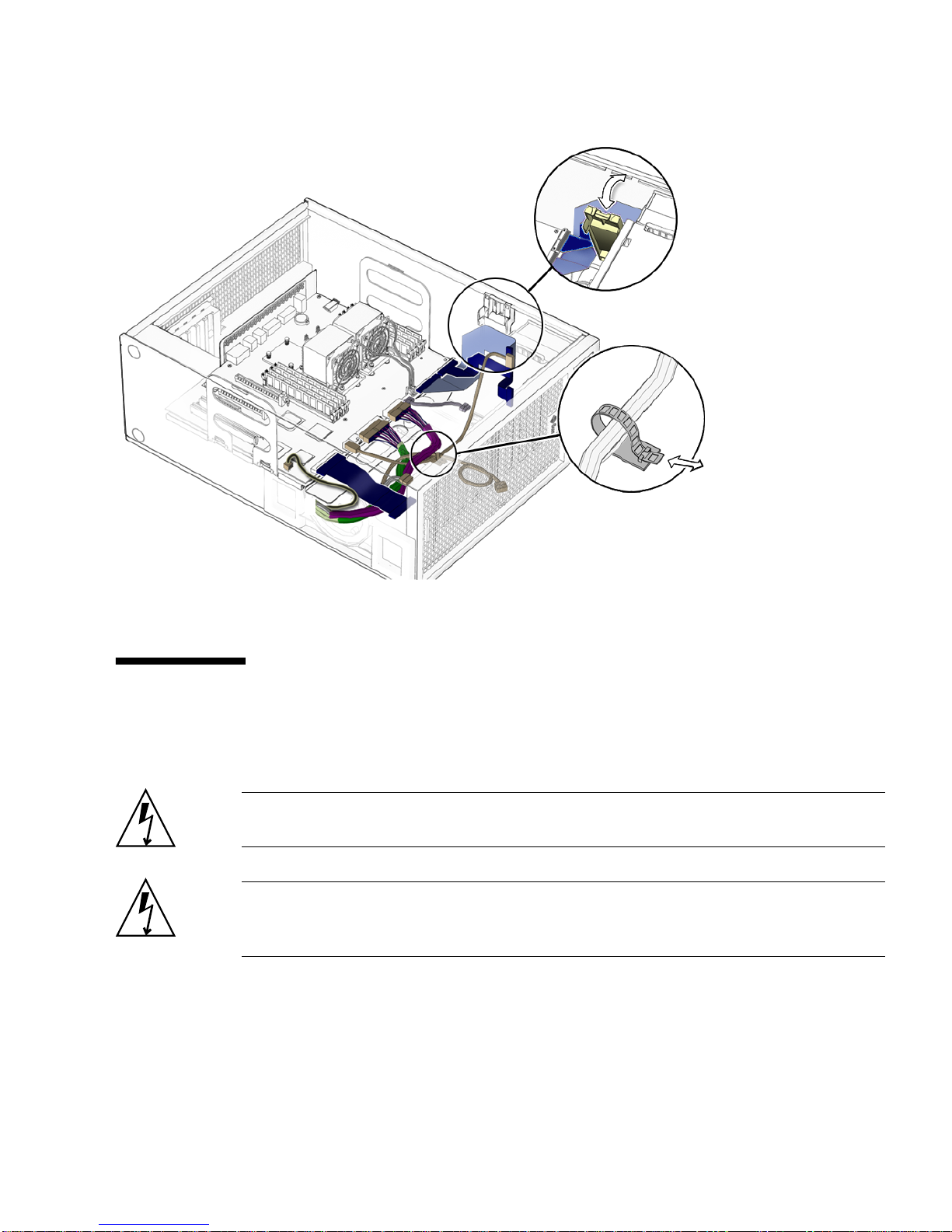
FIGURE 3-2 Motherboard Cables and Cable Clips
3.2 Replacing the DIMMs
This section describes removal and installation of the memory modules.
Caution – DIMM memory is installed in pairs. If you replace a single DIMM, the
new DIMM must be identical to the DIMM that you removed.
Caution – Handle the DIMMs along the outside edges. Do not handle the DIMM
along the gold contact edge. Do not touch DIMM components or other metal parts.
Always wear an antistatic wrist strap when handling DIMMs.
Chapter 3 Replacing the Motherboard and Associated Components 3-3
Page 42

3.2.1 DIMM Configuration Rules
Sun Ultra 45 or Ultra 25 workstation memory is installed as matched pairs of DDR-1
SDRAM 266-MHz DIMMs. Within a matched pair, DIMMs must be identical. They
must be from the same manufacturer with the same type and number of memory
devices, the same amount of memory per device, and the same memory speed.
■ The Sun Ultra 45 or Ultra 25 workstation requires a minimum of two matching
DIMMs installed in CPU0 (
■ DIMM connectors on the motherboard are color-coded blue and black. Beginning
with CPU0, install DIMMS in pairs, either in the blue or in the black connectors.
■ If you have four DIMMS and two CPUs, install two DIMMs for CPU0 and two for
CPU1 for optimum performance (
When the workstation boots, the OpenBoot PROM checks for compatible memory
modules. See “OpenBoot PROM Memory Message” on page 3-6 for additional
information.
Before replacing Sun Ultra 45 and Ultra 25 memory, verify that the latest versions of
OpenBoot PROM, system firmware, and recommended system patches are installed
on your system. If necessary, check the Sun System Handbook at SunSolve Online:
http://sunsolve.sun.com/handbook_pub/
FIGURE 3-3).
FIGURE 3-4).
FIGURE 3-3 DIMM Configurations for Single-CPU Workstations
Note – The Ultra 25 workstation has one CPU (CPU0) and one bank of four DIMM
slots on the motherboard.
3-4 Sun Ultra 45 and Ultra 25 Workstations Service and Diagnostics Manual • May 2006
Page 43

FIGURE 3-4 DIMM Configurations for Ultra 45 Dual-CPU Workstations
Chapter 3 Replacing the Motherboard and Associated Components 3-5
Page 44

3.2.2 OpenBoot PROM Memory Message
During workstation startup, OpenBoot PROM checks for DIMM type and DIMM
manufacturer.
PROM.
TABLE 3-1 OpenBoot PROM Memory Checks and Actions
Check Message Action Taken by System
TABLE 3-1 shows some checks and the actions taken by the OpenBoot
Wrong DIMM type
DIMMs in a pair have
different architecture
DIMMs in a pair are from
different manufacturers
Note – If you only have one DIMM pair installed and those DIMMs have different
architectures, the OpenBoot PROM displays a message, and powers off.
Each CPU has four memory slots. The two blue slots make up physical bank 0 and
the two black slots make up physical bank 1 (
If a problem is found, OpenBoot PROM references memory by bank, for example:
NOTICE - CPU0 Bank 0 DIMMS are from different vendors.
NOTICE - CPUx Banky DIMMs
are incorrect type.
NOTICE - CPUx Banky DIMMs
have different
architectures and will not
be used.
NOTICE - CPUx Banky DIMMs
are from different
vendors.
A message is displayed and the
workstation powers off.
Workstation does not use dissimilar
DIMMs. A message is displayed and the
workstation continues to boot; the
workstation attempts to use the DIMM
pair.
Workstation uses DIMMs from different
manufacturers. A message is displayed
and the workstation continues to boot.
FIGURE 3-4).
The preceding message means that each of the two DIMMs in the bank 0 slots comes
from a different manufacturer. The workstation still attempts to use the DIMMs.
NOTICE - CPU0 Bank 1 DIMMs have different architectures and will
not be used.
This message means that each of the two DIMMs in the black slots has a different
internal memory layout. The workstation does not use the DIMMs.
The workstation must have at least one functional pair of DIMMs to display a
message. A workstation with more than one pair of DIMMs might display more than
one message.
3-6 Sun Ultra 45 and Ultra 25 Workstations Service and Diagnostics Manual • May 2006
Page 45

3.2.3 Removing the DIMMs
1. Power off the system and attach an antistatic wrist strap. Open and position the
chassis, and remove the access panel.
Refer to “Powering Off the Workstation” on page 2-4.
2. Release the DIMM by simultaneously pressing down on both ejector levers at the
ends of the DIMM slot (
FIGURE 3-5).
FIGURE 3-5 Releasing the DIMM
3. Lift the DIMM straight out of the DIMM slot (FIGURE 3-5).
Caution – Handle the DIMMs along the outside edges. Do not handle DIMMs
along the gold edge. Do not touch DIMM components or other metal parts. Always
wear an antistatic wrist strap when handling DIMMs.
Caution – Do not lift the DIMM out of the DIMM slot at an angle. This can damage
the edge connector for the DIMM or the DIMM slot.
DIMM connector key
Chapter 3 Replacing the Motherboard and Associated Components 3-7
Page 46

4. Set the DIMM aside on an antistatic mat.
5. Repeat Step 2 through Step 4 until you have removed all relevant DIMMs.
3.2.4 Installing the DIMMs
Caution – If you are installing additional memory, remember that DIMMs must be
installed in matched pairs of DIMMs (
minimum of one pair of matching DIMMs.
The minimum OpenBoot Prom level for the Sun Ultra 45 or Ultra 25 workstations is
OpenBoot 4.21.x. Before installing Sun Ultra 45 and Ultra 25 memory, verify that the
latest versions of OpenBoot PROM, system firmware, and recommended system
patches are installed on your system. If necessary, check the Sun System Handbook at
SunSolve Online:
http://sunsolve.sun.com/handbook_pub/
Note – If your Ultra 45 workstation has two CPUs and four DIMMs, the
workstation operates most efficiently with two DIMMs per CPU. DIMM connectors
are color-coded blue and black. You must install DIMMs in pairs in the same color
connectors.
FIGURE 3-4). The workstation requires a
Caution – Use proper ESD grounding techniques when handling components. Wear
an antistatic wrist strap and use an antistatic mat. Store ESD-sensitive components in
antistatic bags before placing them on any surface.
Caution – Do not remove any DIMM from its antistatic package until you are ready
to install it.
1. Power off the system, attach an antistatic wrist strap, open and position the
chassis, and remove the access panel.
Refer to “Powering Off the Workstation” on page 2-4.
2. Remove the new DIMM from its antistatic container.
Caution – Handle DIMMs only by the edges. Do not touch DIMM components or
metal parts. Always wear an antistatic wrist strap when handling DIMMs.
3-8 Sun Ultra 45 and Ultra 25 Workstations Service and Diagnostics Manual • May 2006
Page 47

3. Review the recommended DIMM installation and configurations before installing
the DIMM.
See “Replacing the DIMMs” on page 3-3.
Caution – If you replace a single DIMM, the replacement DIMM must be identical
to the DIMM that you removed.
4. Align the DIMM notch to the DIMM connector key (
5. Using both thumbs, press the DIMM straight down into the DIMM connector slot
until both ejector levers close (
FIGURE 3-5).
The DIMM is seated when you hear a click and the ejector levers are in the vertical
position.
6. Repeat Step 4 through Step 5 until all DIMMs are installed.
7. Verify that all DIMM ejector levers are upright, seated, and tight.
8. Reassemble the workstation, power on the system, and verify the DIMM
installation.
Refer to “Reassembling the Workstation” on page 6-1 and “Verifying Component
Installation” on page 6-5. You also might want to review the information in
“OpenBoot PROM Memory Message” on page 3-6.
3.3 Replacing the Battery
This section describes removal and installation of the battery. TABLE 3-2 lists the
battery specifications.
FIGURE 3-5).
TABLE 3-2 Battery Specifications
Specification Value
Voltage 3 VDC
Type CR 2032
Chapter 3 Replacing the Motherboard and Associated Components 3-9
Page 48

3.3.1 Removing the Battery
1. Power off the system and attach an antistatic wrist strap. Open and position the
chassis, and remove the access panel.
Refer to “Powering Off the Workstation” on page 2-4.
2. Release the battery by pressing the battery clip away from the battery until the
battery shifts out of the battery socket (
3. Remove the battery.
FIGURE 3-6).
FIGURE 3-6 Removing and Installing the Battery
Note – The workstation does not function without the battery.
3-10 Sun Ultra 45 and Ultra 25 Workstations Service and Diagnostics Manual • May 2006
Battery clip
Page 49

3.3.2 Installing the Battery
The battery fits directly into a socket on the motherboard. There are no additional
fasteners or cables.
1. Position the battery over the battery socket with the plus (+) side up (
2. Press the battery down into the socket until the battery clicks into place.
3. Reassemble the workstation, power on the system, and verify the battery
installation.
Refer to “Finishing Component Replacement” on page 6-1 and “Verifying
Component Installation” on page 6-5.
3.4 Replacing the NVRAM
This section describes removal and installation of the nonvolatile random access
memory (NVRAM).
Note – If you are replacing a motherboard and you have software that is licensed to
the HostID or Ethernet address, you should install the old NVRAM on the new
motherboard.
FIGURE 3-6).
3.4.1 Removing the NVRAM
1. Power off the system and attach an antistatic wrist strap. Open and position the
chassis, and remove the access panel.
Refer to “Powering Off the Workstation” on page 2-4.
2. Pull the NVRAM straight up from the motherboard connector (
Chapter 3 Replacing the Motherboard and Associated Components 3-11
FIGURE 3-7).
Page 50
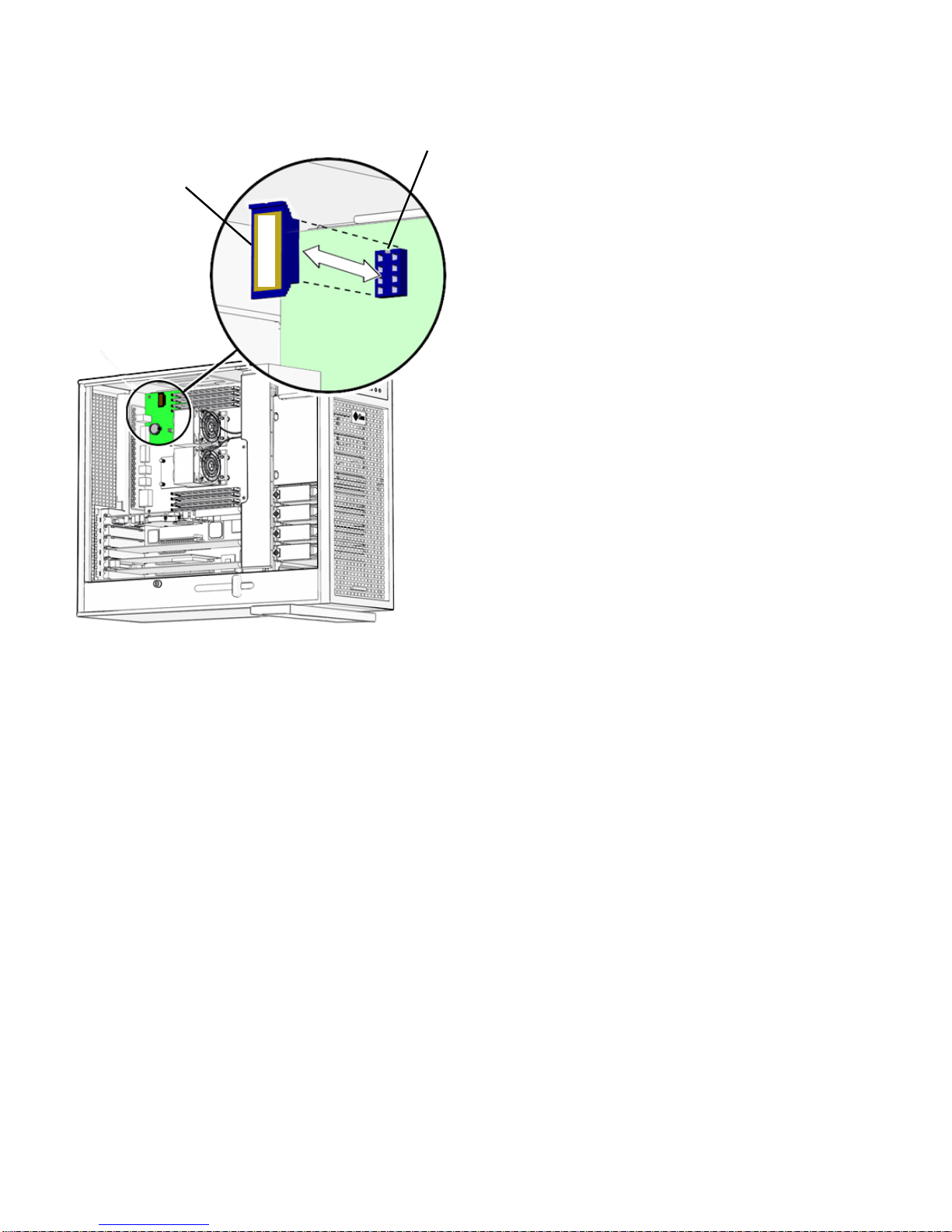
MAC address
NVRAM key
12345678
FIGURE 3-7 Removing and Installing the NVRAM
3. Set the NVRAM aside on an antistatic mat.
3.4.2 Installing the NVRAM
The NVRAM installs directly onto the motherboard. There are no additional
fasteners or cables.
1. Power off the system and attach an antistatic wrist strap. Open and position the
chassis, and remove the access panel.
Refer to “Powering Off the Workstation” on page 2-4.
2. Align the NVRAM key to the NVRAM connector key on the motherboard
(
FIGURE 3-7).
3. Press the NVRAM down into the connector.
4. Ensure that the NVRAM is tight in its connector.
3-12 Sun Ultra 45 and Ultra 25 Workstations Service and Diagnostics Manual • May 2006
Page 51

5. If you are finished working, reassemble the workstation, power on the
workstation, and verify the NVRAM installation.
Refer to “Finishing Component Replacement” on page 6-1 and “Verifying
Component Installation” on page 6-5.
3.5 Replacing the PCI Cards
This section describes removal and installation of PCI cards in the workstation.
3.5.1 Identifying the PCI Cards
There are five PCI connectors on the system motherboard. Two connectors are PCI-X,
and three connectors are PCI-Express (
physical lanes long and operate at x8 lanes. The short PCI-E connector is x8 lanes
long and operates at x4 lanes.
FIGURE 3-8). The long PCI-E connectors are x16
Chapter 3 Replacing the Motherboard and Associated Components 3-13
Page 52

PCI-E2 x8
Blank slot
PCI-E1 x8
PCI-E0 x4
PCI-X1 100 MHz
PCI-X0 100 MHz
FIGURE 3-8 PCI Card Location and Identification
3.5.2 Removing a PCI Card
1. Power off the system and attach an antistatic wrist strap. If necessary, disconnect
external cables. Open and position the chassis, and remove the access panel.
Refer to “Powering Off the Workstation” on page 2-4.
2. Using a No. 2 Phillips screwdriver, remove the screw that secures the PCI card
retainer to the chassis rear panel (
Set the screw aside in a container.
Caution – If you are removing a graphics accelerator from a PCI-Express connector,
be sure that you release the PCI-E connector latch (FIGURE 3-9).
3-14 Sun Ultra 45 and Ultra 25 Workstations Service and Diagnostics Manual • May 2006
FIGURE 3-9).
Page 53

3. Gently rock the PCI card forward, then lift it straight out of the PCI card slot, and
set it aside on an antistatic mat.
FIGURE 3-9 Removing the PCI Card
4. If you are not installing another PCI card in the empty slot, insert a filler panel
into the rear panel slot.
The rear panel slot must be closed with a filler panel to meet system Electromagnetic
Interference (EMI) and airflow requirements.
3.5.3 General PCI Card Guidelines
The total power consumption of all installed PCI cards must not exceed 400 Watts.
Chapter 3 Replacing the Motherboard and Associated Components 3-15
Page 54

3.5.4 Installation Considerations for Graphics
Accelerators
PCI-E 2 is the default console display. If there is no graphics accelerator installed
into PCI-E 2, consider the probe order shown in
3.5.4.1 Default Console Display
During the boot sequence, device nodes are probed. The PCI slots are probed in the
order described in
TABLE 3-3 PCI Card Probe Order
Probe
Order Slot Identifier Device Node
1 PCI4 (PCI-E 2) /pci@1f,700000/ device 0
2 PCI2 (PCI-E 0) /pci@1e,600000/pci@0/pci@3/ device 0
3 PCI3 (PCI-E 1) /pci@1e,600000/pci@0/pci@8/ device 0
4 PCI1 (PCI-X 1) /pci@1e,600000/pci@0/pci@9/pci@0,2/ device 1
TABLE 3-3.
TABLE 3-3.
5 PCI0 (PCI-X 0) /pci@1e,600000/pci@0/pci@9/pci@0,2/ device 2
Unless you reconfigure the default, the first graphics accelerator occurring in the
probe order is designated the default console display and assigned the aliases
screen and /dev/fb.
3.5.4.2 Changing the Console Display
You can configure the OpenBoot PROM to designate a different graphics accelerator
as the console display. Use the show-displays utility, the nvalias command, and
the output-device parameter to make this change. For the following example, a
Sun XVR-2500 graphics accelerator is installed in physical slot PCI-E 2 as the default
console display and a Sun XVR-100 graphics accelerator is installed in slot PCI-X 0.
This example configures the Sun XVR-100 graphics accelerator to be the new console
display.
1. Obtain the ok prompt.
See “Obtaining the ok Prompt” on page 10-2.
3-16 Sun Ultra 45 and Ultra 25 Workstations Service and Diagnostics Manual • May 2006
Page 55

2. Display the device nodes for the installed graphics accelerators.
For example:
ok show-displays
a) /pci@1f,700000/SUNW,XVR-2500@0
b)
/pci@1e,600000/pci@0/pci@9/pci@0,2/SUNW,XVR-100@2
q) NO SELECTION
3. Select the graphics accelerator to be the new console display by typing its
respective letter.
For example:
Enter Selection, q to quit: b
The utility ends and the device node path is loaded into a text buffer.
4. Make an alias for the device node path.
For example:
ok nvalias newconsoledisplay (Ctrl + Y)
Type a space, hold down the Control key, and press the Y key.
5. Configure the output-device parameter for the new console display.
For example:
ok setenv output-device newconsoledisplay
6. Reset the OpenBoot PROM:
ok reset-all
The system now uses the Sun XVR-100 graphics accelerator as the new console
display.
Note – The default console display, the first graphics accelerator found in probe
order, is still aliased to screen. If you want to check the new console display, type:
test newconsoledisplay
Chapter 3 Replacing the Motherboard and Associated Components 3-17
Page 56

3.5.5 Installing a PCI Card
1. Power off the system and attach an antistatic wrist strap. If necessary, disconnect
external cables. Open and position the chassis, and remove the access panel.
Refer to “Powering Off the Workstation” on page 2-4.
2. Locate the available PCI card slots.
You might have to remove a second chassis filler panel for some PCI cards that use
two PCI card slots. Read the documentation that came with the PCI card and see
“General PCI Card Guidelines” on page 3-15.
FIGURE 3-10 Installing a PCI Card
3-18 Sun Ultra 45 and Ultra 25 Workstations Service and Diagnostics Manual • May 2006
Page 57

3. Using a No. 2 Phillips screwdriver, remove the chassis filler panel from the PCI
card slot and set the screw aside in a container (
FIGURE 3-10).
Remove a second filler panel if needed for dual-width PCI cards.
4. Remove the new PCI card from its antistatic container.
Caution – Handle the PCI card along the outside edges. Do not handle the PCI card
along the contact edge. If you are installing a long PCI-E card, be sure to engage the
PCI-E connector latch.
5. Position the PCI card so that the PCI bracket aligns with the chassis rear panel
slot and the PCI card edge aligns with the motherboard PCI card connector.
6. Insert the PCI card into the PCI card slot.
If you are installing a long PCI-Express card, be sure to engage the PCI-E connector
latch (
FIGURE 3-10).
7. Firmly press the PCI card straight down into the PCI card slot until it is fully
seated in the slot.
8. Use a No. 2 Phillips screwdriver to fasten the screw that secures the PCI card
retainer (
FIGURE 3-10).
9. Inspect the PCI card fasteners to verify that:
■ The PCI card panel slot screws are tight.
■ The PCI cards are secure in the connectors.
10. If you are finished working, reassemble the workstation, power on the
workstation, and verify the PCI card installation.
Refer to “Finishing Component Replacement” on page 6-1.
Note – Boot the system with the -r option, so that the Solaris Operating System can
reconfigure itself for the new component. See “Finishing Component Replacement”
on page 6-1.
Chapter 3 Replacing the Motherboard and Associated Components 3-19
Page 58
3.6 Replacing the Motherboard
This section describes removal and installation of the motherboard.
Caution – This procedure is intended for Sun authorized service providers only.
3.6.1 Removing the Motherboard
The motherboard, CPU, and NVRAM are a single replaceable unit.
1. Power off the system and attach an antistatic wrist strap. Disconnect all external
cables; open and position the chassis, and remove the access panel.
Refer to “Powering Off the Workstation” on page 2-4.
2. If necessary, remove the PCI cards and DIMMs (
Refer to:
■ “Removing the DIMMs” on page 3-7
■ “Removing a PCI Card” on page 3-14
Set these components onto an antistatic mat (
3. Remove the fan tray.
4. (Optional) If you want to use the same Ethernet address and system ID for the
new motherboard, remove the NVRAM and place it on an antistatic mat.
Refer to “Removing the NVRAM” on page 3-11.
FIGURE 3-11).
FIGURE 3-11).
Note – If you have software that is licensed to the HostID or Ethernet address, you
should install the old NVRAM on the new motherboard.
5. Remove all cables from the cable clips (
FIGURE 3-11).
3-20 Sun Ultra 45 and Ultra 25 Workstations Service and Diagnostics Manual • May 2006
Page 59

FIGURE 3-11 Removing Components from the Motherboard
Chapter 3 Replacing the Motherboard and Associated Components 3-21
Page 60

6. Disconnect the following power and signal cables from the motherboard
(
FIGURE 3-12):
■ I/O module signal and power cable at connector J3
■ I/O module USB cable at connector J36
■ DVD-dual drive cable at connector J11
■ Fan tray backplane cable at connector J20
■ Power supply cables at connectors J22, J28, J45 (P1, P2, and P5)
■ Hard drive signal cable connector J42
FIGURE 3-12 Disconnecting Motherboard Cables
7. Turn the motherboard latch 90 degrees counterclockwise (FIGURE 3-13).
3-22 Sun Ultra 45 and Ultra 25 Workstations Service and Diagnostics Manual • May 2006
Page 61

Motherboard handle
Motherboard handle
Motherboard latch
FIGURE 3-13 Releasing the Motherboard Latch
8. Move the cables out of the way.
9. Using the motherboard handles, tilt the motherboard to one side and lift it until it
is free of the chassis (
FIGURE 3-13).
10. Set the motherboard down onto the antistatic mat.
3.6.2 Installing the Motherboard
1. Remove the new motherboard from its antistatic package and place it on an
antistatic mat.
2. Move all cables out of the way.
3. Align the motherboard rear panel connectors with the matching holes in the rear
panel (
FIGURE 3-13).
Chapter 3 Replacing the Motherboard and Associated Components 3-23
Page 62

4. Gently lower the motherboard while tilting it down (FIGURE 3-13).
5. Align the motherboard so that the hooks fit into the holes of the motherboard tray.
Caution – Ensure that the hooks are located in the holes. Improper alignment can
damage the motherboard.
6. Turn the motherboard latch 90 degrees clockwise to secure the motherboard.
Ensure that the motherboard connector panel aligns with the chassis rear panel.
7. Connect the cables to the corresponding motherboard connectors (
■ I/O module signal and power cable at connector J3
■ I/O module USB cable at connector J36
■ DVD-dual drive connector at J11
■ Fan tray backplane cable at connector J20
■ Power supply cables at connectors J22, J28, and J45 (P1, P2, and P5)
■ Hard drive signal cable connector J42
FIGURE 3-14):
3-24 Sun Ultra 45 and Ultra 25 Workstations Service and Diagnostics Manual • May 2006
Page 63

DVD-dual drive
J22 (P2)
J28 (P1)
J45/P5
J3
J11
J20
J36
J42
I/O module
Fan tray backplane
P4
(not used)
J2
Power supply
FIGURE 3-14 Reconnecting Cables to the Motherboard
8. Secure the cables into the cable clips (FIGURE 3-14).
9. If necessary, install the old NVRAM onto the new motherboard (
Refer to “Replacing the NVRAM” on page 3-11.
Note – If you have software that is licensed to the HostID or Ethernet address, you
should install the old NVRAM on the new motherboard.
Hard drive backplane
FIGURE 3-15).
Chapter 3 Replacing the Motherboard and Associated Components 3-25
Page 64

10. Install the PCI cards and the DIMMs.
Refer to:
■ “Installing a PCI Card” on page 3-18
■ “Replacing the DIMMs” on page 3-3
11. Inspect the motherboard to verify that:
■ Cable connections are tight and cable clips are secured.
■ DIMMs are properly installed.
■ NVRAM is tight in the socket.
■ PCI cards are properly seated and secured.
12. Reassemble the workstation, power on the system, and verify the motherboard
installation.
Refer to “Finishing Component Replacement” on page 6-1.
3-26 Sun Ultra 45 and Ultra 25 Workstations Service and Diagnostics Manual • May 2006
Page 65

FIGURE 3-15 Installing the Motherboard and Related Components
Chapter 3 Replacing the Motherboard and Associated Components 3-27
Page 66

3-28 Sun Ultra 45 and Ultra 25 Workstations Service and Diagnostics Manual • May 2006
Page 67

CHAPTER
4
Replacing Storage Devices
This chapter describes the removal and installation procedures for Sun Ultra 45 or
Ultra 25 workstation storage devices.
The procedures described in this chapter are written for workstation service
providers and system administrators.
This chapter contains the following topics:
■ Section 4.1, “Replacing a Hard Drive” on page 4-2
■ Section 4.2, “Replacing the Hard Drive Backplane and Cables” on page 4-4
■ Section 4.3, “Replacing the I/O Module With the DVD-Dual Drive and Audio
USB Board” on page 4-6
Caution – To prevent equipment damage, review the safety information in
“Preparing to Replace Components” on page 2-1 before you perform any
replacement procedure. Additional cautions, warnings, and instructions are
provided in the Sun Ultra 45 and Ultra 25 Workstations Safety and Compliance Guide
819-2785. The document is available from:
http://www.sun.com/documentation.
,
Caution – When servicing or removing workstation components, attach an
antistatic strap to your wrist and then to a metal area on the chassis. Then disconnect
the power cord from the workstation and the wall receptacle. Following this caution
equalizes all electrical potentials with the workstation.
4-1
Page 68

4.1 Replacing a Hard Drive
The workstation supports up to four hard drives, either serial ATA (SATA), or serial
attached SCSI (SAS). The hard drives slide into the hard drive bay and use standard
Sun hard drive mounting brackets.
Note – Sun does not support mixed SAS and SATA hard drives. All four installed
hard drives must be the same type.
Caution – The Sun SATA and SAS hard drive brackets are gray. To prevent damage
to the connectors, do not insert any other color of hard drive into Sun Ultra 45 or
Ultra 25 workstations.
The hard drives are labeled HDD0 through HDD3. The default boot drive is HDD0
FIGURE 4-1).
(
TABLE 4-1 lists the hard drive specifications.
TABLE 4-1 Hard Drive Specifications
Hard Drive Specification
SATA 100 250GB, 7,200 rpm, 3.5 inch, (gray bracket)
80GB, 7,200 rpm, 3.5 inch, (gray bracket) for
Ultra 25 workstation.
SAS 146GB, 15,000 rpm, 3.5 inch (gray bracket)
4.1.1 Removing a Hard Drive
1. Power off the system and attach an antistatic wrist strap. Open and position the
chassis, and remove the access panel.
Refer To “Powering Off the Workstation” on page 2-4.
2. Press the hard drive release button to release the hard drive handle (
3. Grasp the hard drive handle and pull the hard drive out of the hard drive bay.
4. Set the hard drive aside on an antistatic mat.
4-2 Sun Ultra 45 and Ultra 25 Workstations Service and Diagnostics Manual • May 2006
FIGURE 4-1).
Page 69

FIGURE 4-1 Removing the Hard Drive
4.1.2 Installing a Hard Drive
HDD0
Caution – Use proper ESD grounding technique when handling components. Wear
an antistatic wrist strap and use an antistatic mat. Store ESD-sensitive components in
antistatic bags before placing them on any surface.
1. Power off the system and attach an antistatic wrist strap. Open and position the
chassis, and remove the access panel.
Refer to “Powering Off the Workstation” on page 2-4.
Chapter 4 Replacing Storage Devices 4-3
Page 70

Note – The default boot device is installed in HDD0 (drive 0). Be sure to install the
boot disk in HDD0, unless you have changed the boot device parameters.
2. Remove the new hard drive from its packaging.
Caution – The Sun SATA and SAS hard drive brackets are color-coded gray. To
prevent damage to the connectors, do not insert any other color of hard drive into
Sun Ultra 45 or Ultra 25 workstations.
3. Install the hard drive (
4. Slide the hard drive into the hard drive bay.
5. Close the latch on the hard drive until it clicks and is secure.
6. If you are finished working, reassemble the workstation, power on the
workstation, and verify the hard drive installation.
See “Finishing Component Replacement” on page 6-1.
Note – Boot the system with the -r option, so that the Solaris Operating System can
reconfigure itself for the new component. See “Finishing Component Replacement”
on page 6-1.
FIGURE 4-1).
4.2 Replacing the Hard Drive Backplane and
Cables
This section describes removal and installation of the hard drive backplane, the
signal cable, and the power cable.
4.2.1 Removing the Hard Drive Backplane and Cables
1. Power off the system and attach an antistatic wrist strap. Open and position the
chassis, and remove the access panel.
Refer to “Powering Off the Workstation” on page 2-4.
4-4 Sun Ultra 45 and Ultra 25 Workstations Service and Diagnostics Manual • May 2006
Page 71

FIGURE 4-2 Disconnecting the Cables From the Hard Drive Backplane
2. Remove all hard drives.
See “Replacing a Hard Drive” on page 4-2.
3. Remove long PCI cards if they are covering the hard drive backplane cables.
Refer to “Removing a PCI Card” on page 3-14. Set these components onto an
antistatic mat.
4. Disconnect the cables from the following connectors
■ Hard drive backplane signal cable from J4 of the hard drive backplane and J42 on
the motherboard (
■ Power cable P3 from backplane connector J2
FIGURE 4-2)
5. Using a No. 2 Phillips screwdriver, remove the two screws from the hard drive
backplane.
Chapter 4 Replacing Storage Devices 4-5
Page 72

4.2.2 Installing the Hard Drive Backplane and Cables
1. Remove the new hard drive backplane and cables from the packaging.
2. Using a No. 2 Phillips screwdriver, replace the two screws for the hard drive
backplane.
3. Reconnect the cables to the following connectors:
■ Power cable P3 on backplane connector J2 (FIGURE 4-2).
■ Hard drive backplane signal cable from J4 of the hard drive backplane and J42 on
the motherboard
4. Inspect the cabling to verify that the signal and power cables are both secure at
the backplane and the motherboard.
5. If you removed any long PCI cards, replace them.
Refer to “Installing a PCI Card” on page 3-18.
6. Reassemble the workstation. Power on the system, and verify the cable
installation.
Refer to:
■ “Reassembling the Workstation” on page 6-1
■ “Verifying Component Installation” on page 6-5
4.3 Replacing the I/O Module With the
DVD-Dual Drive and Audio USB Board
This section describes removal and installation of the I/O module. The I/O module
contains the DVD-dual drive, the audio USB board with speaker, USB and audio
connectors, and the Power button and LED.
4.3.1 Removing the I/O Module and DVD-Dual Drive
1. Power off the system and attach an antistatic wrist strap. Open and position the
chassis, and remove the access panel.
Refer to “Powering Off the Workstation” on page 2-4.
2. Open the I/O cable clip at the top of the chassis (
3. Disconnect the following cables:
4-6 Sun Ultra 45 and Ultra 25 Workstations Service and Diagnostics Manual • May 2006
FIGURE 4-3).
Page 73

■ Audio and power cable at J3 on the motherboard
■ DVD cable at J11 on the motherboard
■ USB cable from at J36 on the motherboard.
New cables are provided with the DVD-dual drive and the I/O module.
If you need to remove a long PCI card to access the USB cable, refer to “Removing a
PCI Card” on page 3-14.
4. Press the I/O module release button and pull the I/O module out the front of the
chassis.
Place the I/O module on an antistatic mat.
Caution – Do not attempt to remove the bezel from the front of the I/O module.
FIGURE 4-3 Removing the I/O Module With the DVD-Dual Drive and Audio USB Board
Chapter 4 Replacing Storage Devices 4-7
Page 74

5. If you are only replacing the DVD-dual drive:
a. Using a No. 0 Phillips screwdriver, remove the screws holding the DVD-dual
drive into the I/O module.
b. Pull the DVD-dual drive straight out the back of the removable media bay
(
FIGURE 4-3).
6. If you are replacing the audio USB board:
a. Remove the DVD-dual drive and set it aside.
b. Using a No. 2 Phillips screwdriver, remove the four screws that secure the
audio USB board to the I/O module.
c. Pull the audio USB board straight out the back of the removable media bay
(
FIGURE 4-3).
4.3.2 Installing the I/O Module and DVD-Dual Drive
1. Remove the I/O module and DVD-dual drive assembly from the packaging.
2. If you are replacing the audio USB board:
a. Install the new audio USB board into the removable media bay (
FIGURE 4-3).
b. Replace all four screws that secure the audio USB board to the removable
media bay.
3. Install the DVD-dual drive into the I/O module with the screws (
FIGURE 4-3):
a. If you are using the old DVD-dual drive, screw the old drive into the I/O
module.
b. If you are using a new DVD-dual drive, screw the new drive into the I/O
module.
4. Push the I/O module and DVD-dual drive into the chassis until the module clicks
(
FIGURE 4-3).
5. Connect the cables to the DVD-dual drive and the audio USB board.
If you removed a long PCI card, replace it now. Refer to Section 3.5.5, “Installing a
PCI Card” on page 3-18.
Note – Always use the new cables that are shipped with the DVD-dual drive or I/O
module.
4-8 Sun Ultra 45 and Ultra 25 Workstations Service and Diagnostics Manual • May 2006
Page 75

6. Guide the DVD and audio/power cables through the I/O cable clip at the top of
the chassis and close the clip.
7. Reconnect the audio and USB cables to:
■ Audio and power cable at J3 on the motherboard and J0201 on the audio USB
board (
■ DVD cable at J11 on the motherboard and J501 on the DVD-dual drive
■ USB cable at J36 on the motherboard and J0601 on the audio USB board
FIGURE 4-3 and FIGURE 4-4)
FIGURE 4-4 Securing the Audio USB Cables in the I/O Cable Clip
8. Inspect the audio USB board cabling to verify that:
■ The I/O cable clip is closed and locked.
■ The USB cable is secured in the cable clip on the hard drive bay.
9. Reassemble the workstation. Power on the system, and verify the audio USB
board installation.
Refer to “Reassembling the Workstation” on page 6-1.
Chapter 4 Replacing Storage Devices 4-9
Page 76

Note – Boot the system with the -r option, so that the Solaris Operating System can
reconfigure itself for the new component. Refer to “Finishing Component
Replacement” on page 6-1.
4-10 Sun Ultra 45 and Ultra 25 Workstations Service and Diagnostics Manual • May 2006
Page 77

CHAPTER
5
Replacing Chassis Components
This chapter describes the removal and installation procedures for the Sun Ultra 45
or Ultra 25 workstation chassis components.
This chapter contains the following topics:
■ Section 5.1, “Replacing the Fan Tray and Fan Tray Backplane” on page 5-1
■ Section 5.2, “Replacing the Power Supply” on page 5-4
Caution – To prevent equipment damage, review the safety requirements, safety
symbols, and safety precautions in “Preparing to Replace Components” on page 2-1
before you perform any replacement procedure. Additional cautions, warnings, and
instructions are provided in the Sun Ultra 45 and Ultra 25 Workstations Safety and
Compliance Guide, 819-2785. The document is available from:
http://www.sun.com/documentation.
Caution – When servicing workstation components, attach an antistatic strap to
your wrist and then to a metal area on the chassis. Then disconnect the power cord
from the workstation and the wall receptacle. Following this caution equalizes all
electrical potentials with the workstation.
5.1 Replacing the Fan Tray and Fan Tray
Backplane
This section describes removal and installation of the fan tray and fan tray
backplane.
5-1
Page 78

Caution – Do not operate the workstation without the fan tray.
5.1.1 Removing the Fan Tray
1. Power off the system and attach an antistatic wrist strap. Open and position the
chassis, and remove the access panel.
Refer to “Powering Off the Workstation” on page 2-4.
2. Using the handle, pull the fan tray from the chassis and set it aside.
Fan tray handle
FIGURE 5-1 Removing the Fan Tray
5-2 Sun Ultra 45 and Ultra 25 Workstations Service and Diagnostics Manual • May 2006
Page 79

5.1.2 Removing the Fan Tray Backplane
1. Disconnect the fan tray backplane from the motherboard at connector J20
(
FIGURE 5-1).
2. Using a No. 2 Phillips screwdriver, remove the screws for the fan tray backplane.
FIGURE 5-2 Removing the Fan Tray Backplane
5.1.3 Installing the Fan Tray and Fan Tray Backplane
1. Using a No. 2 Phillips screwdriver, mount the backplane to the chassis.
Do not overtighten the screws.
2. Connect the fan tray cable to the backplane and to the motherboard at connector
J20.
Chapter 5 Replacing Chassis Components 5-3
Page 80

3. Align the fan tray in the chassis slot so that the connector is closest to the top of
the chassis (
4. If you are finished working, reassemble the workstation and power on the
workstation.
Refer to “Reassembling the Workstation” on page 6-1.
FIGURE 5-2).
5.2 Replacing the Power Supply
This section describes removal and installation of the power supply.
5.2.1 Removing the Power Supply
1. Power off the system and attach an antistatic wrist strap. Open and position the
chassis, and remove the access panel.
Refer to “Powering Off the Workstation” on page 2-4.
1. If necessary, remove any long PCI cards that are blocking the cables.
Place the PCI card on an antistatic mat.
2. Remove the fan tray.
5-4 Sun Ultra 45 and Ultra 25 Workstations Service and Diagnostics Manual • May 2006
Page 81

FIGURE 5-3 Removing the Power Supply
3. Squeeze the power supply connector clip to disconnect the following cables from
the motherboard (
■ P2 power cable on the motherboard (J22)
■ P1 power cable on the motherboard at (J28)
■ P5 power supply signal cable on the motherboard (J45)
FIGURE 5-3).
4. Disconnect the following cables from the hard drive backplane
■ P3 hard drive backplane power cable on the hard drive backplane (J2)
■ Hard drive signal cable to J4 on the hard drive backplane. (This cable also serves
as a cable clip over other cables).
5. Turn the captive screw that secures the power supply to the chassis (
6. Using the handle, push the power supply out of the back of the chassis.
FIGURE 5-3).
Chapter 5 Replacing Chassis Components 5-5
Page 82

7. Guide the power cables out of the chassis as you push the power supply out the
back of the chassis.
Set the power supply aside on an antistatic mat.
Proceed to “Installing the Power Supply” on page 5-6.
5.2.2 Installing the Power Supply
1. Remove the new power supply from its package.
2. Align the power supply IEC-320 connector so that the power cord socket is nearest
the left rear of the chassis, when viewed from the back (
FIGURE 5-4).
5-6 Sun Ultra 45 and Ultra 25 Workstations Service and Diagnostics Manual • May 2006
Page 83

FIGURE 5-4 Installing the Power Supply
3. Guide the cables and push the power supply into the chassis opening until the
back of the power supply aligns with the back of the chassis.
4. Tighten the captive screw that secures the power supply to the chassis (
5. Connect the following cables (
■ P1 power cable on the motherboard at (J28)
■ P2 power cable on the motherboard (J22)
■ P3 hard drive backplane power cable on the hard drive backplane (J2)
■ P5 power supply signal cable on the motherboard (J45)
FIGURE 5-4).
FIGURE 5-5):
Chapter 5 Replacing Chassis Components 5-7
Page 84

■ Hard drive signal cable to J4 on the hard drive backplane. (This cable also serves
as a cable clip over other cables).
DVD-dual drive
J28 (P1)
J45/P5
J3
J11
J20
J22/P2
J36
J42
I/O module
Fan tray backplane
P4
(not used)
J2
Power supply
FIGURE 5-5 Power Supply Cable Connections at Motherboard and Hard Drive Backplane
6. Inspect the power supply fasteners to verify that:
■ The power supply push bar is seated.
■ The power supply captive screw is tight.
7. Inspect the power supply cabling to verify that:
5-8 Sun Ultra 45 and Ultra 25 Workstations Service and Diagnostics Manual • May 2006
Hard drive backplane
Page 85

■ The three power supply cables are firmly connected to the motherboard at P1, P2,
and P5 (J45).
■ The hard drive backplane power cable is firmly connected at J4.
■ The hard drive backplane signal cable is securely connected at both ends and is
routed over the other cables.
8. Install the fan tray.
9. If you removed any PCI cards, re-install them.
See Section 3.5.5, “Installing a PCI Card” on page 3-18.
10. Reasemble the workstation. Power on the system, and verify the power supply
installation.
Refer to “Reassembling the Workstation” on page 6-1.
Note – Boot the system with the -r option, so that the Solaris Operating System can
reconfigure itself for the new component. See “Finishing Component Replacement”
on page 6-1.
Chapter 5 Replacing Chassis Components 5-9
Page 86

5-10 Sun Ultra 45 and Ultra 25 Workstations Service and Diagnostics Manual • May 2006
Page 87

CHAPTER
6
Finishing Component Replacement
This chapter describes how to finish the replacement of internal workstation
replaceable components, close the system, and prepare it for operation. Topics
covered in this chapter are:
■ Section 6.1, “Reassembling the Workstation” on page 6-1
■ Section 6.2, “Verifying Component Installation” on page 6-5
6.1 Reassembling the Workstation
1. Verify that you have not left any tools, loose screws, or loose components inside
the system.
2. Replace the fan tray if you removed it (
3. Fit the access panel into the chassis (
a. Ensure that the access panel latches are secure.
b. Slide the lock block towards the back of the workstation.
If desired, lock the system or insert a security cable.
4. Remove the wrist strap from the workstation and your wrist.
5. Pivot the support stabilizer from underneath the workstation (
6. Set the chassis upright.
7. Press in the side cover until the latches click.
FIGURE 6-1).
FIGURE 6-1).
FIGURE 6-3).
6-1
Page 88

FIGURE 6-1 Reassembling the Workstation
8. Reconnect the keyboard, mouse, monitor, network connections, and any
peripherals (
FIGURE 6-2).
9. Reconnect the power cord to the workstation and the power source.
6-2 Sun Ultra 45 and Ultra 25 Workstations Service and Diagnostics Manual • May 2006
Page 89

FIGURE 6-2 Reconnecting the Cables
10. Power on any connected peripherals or monitors.
Note – The monitor must be powered on before the workstation so that the monitor
can communicate with the graphics accelerator when the workstation powers on.
11. Power on the workstation.
Chapter 6 Finishing Component Replacement 6-3
Page 90

Power button
FIGURE 6-3 Powering On the Workstation
12. Select a boot source.
For most component installations you should become superuser and reboot the
workstation so that the Solaris OS finds the new component.
For example:
# reboot -- -r
If you are at the ok prompt, type:
ok boot -r
6-4 Sun Ultra 45 and Ultra 25 Workstations Service and Diagnostics Manual • May 2006
Page 91

6.2 Verifying Component Installation
There are several methods for verifying the installation of the new component.
6.2.1 Reconfiguring the System With boot -r Option
1. Boot the system with the -r option, so that the Solaris OS can reconfigure itself
for the new component.
For example:
# boot -- -r
2. Monitor the boot message.
If a warning message is displayed, refer to Section 12.4, “OpenBoot PROM
Messages” on page 12-11.
3. If the problem has not been solved, see “Diagnostics Hierarchy” on page 7-4.
6.2.2 Verifying Configuration With POST
1. Run POST with the diag-switch to true and the diag-level set to max.
2. Verify that the new device is recognized by POST.
Refer to “Power-On Self-Test” on page 11-1.
6.2.3 Verifying Configuration With POST and
OpenBoot Diagnostics
Use OpenBoot Diagnostics to test all devices. Refer to “OpenBoot Diagnostics” on
page 12-6.
6.2.4 Verifying Configuration With prtdiag
From a terminal window, type prtdiag and verify that all the correct devices are
recognized by the system. Refer to “prtdiag Command” on page 9-8.
Chapter 6 Finishing Component Replacement 6-5
Page 92

6-6 Sun Ultra 45 and Ultra 25 Workstations Service and Diagnostics Manual • May 2006
Page 93

CHAPTER
7
Diagnostics Overview
This chapter describes some diagnostic tools. This chapter contains the following
topics:
■ Section 7.1, “Diagnostic Tools Available” on page 7-1
■ Section 7.2, “Diagnostic Tests” on page 7-2
■ Section 7.3, “Power-On Sequence” on page 7-6
7.1 Diagnostic Tools Available
The Sun Ultra 45 and Ultra 25 Workstations Service and Diagnostics Manual uses
displayed messages, system sounds, flowcharts, and firmware and software
diagnostic tools to help you locate and identify workstation malfunctions.
TABLE 7-1 Diagnostic Tools Sorted by Tool Type
Diagnostic Tool Type of Tool What the Tool Does How to Use the Tool
System LEDs Hardware Shows status of system or of
a specific component.
System sounds Hardware Single beep indicates
keyboard connection when
the system boots. Continuous
beeping indicates a stuck key
on the keyboard.
Solaris 10 Predictive
Self-Healing
Software Runtime diagnostics program
that monitors system errors
and reports any hardware
needing replacement.
For information on system power and
Ethernet LEDs, see “LED Diagnostics”
on page 8-1.
If continuous beeping, disconnect and
reconnect keyboard. Inspect for stuck
keys, or replace.
Use Predictive Self-Healing first to
diagnose the workstation.
See: “Predictive Self-Healing Overview”
on page 9-1.
7-1
Page 94

TABLE 7-1 Diagnostic Tools Sorted by Tool Type (Continued)
Diagnostic Tool Type of Tool What the Tool Does How to Use the Tool
Solaris 10 Operating
System
NVRAM Firmware Contains properties and flags
POST diagnostics Firmware Tests workstation core
OpenBoot
Diagnostics
SunVTS Software Exercises and stresses
Software Commands display system
information.
to configure system and
diagnostic tests.
components such as CPU and
memory.
Firmware Tests system motherboard
and component interfaces.
workstation components.
Commands iostat, prtdiag,
prtconf, netstat, ping, ps, and
prstat are run with superuser
privileges. See “Traditional Solaris
Troubleshooting Commands” on
page 9-6.
The setenv command typed at the ok
prompt or the eeprom command in a
terminal window can configure the
OpenBoot PROM for diagnostics and
automatic execution of scripts. See
“NVRAM” on page 10-1.
Checks low-level interaction between
CPU, caches, memory, JBus, and PCI
bridge. Output displayed through serial
port. See “Power-On Self-Test” on
page 11-1.
Component tests are selected from
menu. If component is PCI card with
IEEE 1275-compliant Fcode, internal selftest is executed. See “OpenBoot
Diagnostics” on page 12-6.
Invoked from the Solaris Operating
System. Command-line or GUI user
interface. SunVTS must be installed on
the system under test. See “SunVTS” on
page 13-1.
7.2 Diagnostic Tests
The Predictive Self-Healing (predictive self-healing tools) is often your first and best
tool for diagnostics. Use
troubleshoot a component.
7-2 Sun Ultra 45 and Ultra 25 Workstations Service and Diagnostics Manual • May 2006
TABLE 7-2 to determine which diagnostic program to use to
Page 95

TABLE 7-2 Diagnostics Tools Sorted by Component
Solaris 10 Predictive
Component
Self-Healing POST OpenBoot Diagnostics SunVTS
Diagnoses events and
prescribes corrective
actions.
Tests workstation core
components such as
CPU and memory.
CPU Complete diagnostics Performs cache,
MMU, CPU, and FPU
tests
Memory Complete diagnostics Max diag level
performs tests
including block
memory and quick
memory tests
I/O bridge
chip
Partial diagnostics,
driver dependent
Performs several tests
including register
tests
Flash
PROM
Graphics
accelerator
PCI card Partial diagnostics,
N/A Verification of POST
portion checksum
Partial diagnostics,
driver dependent
Built-in self test
(BIST) only
Built-in self test
driver dependent
(BIST) only
Diagnoses system
motherboard and
component interfaces.
Exercises and stresses
workstation
components.
No testing cputest
iutest
fputest
l1dcachetest
No testing pmemtest
vmemtest
No testing No testing
Yes. See “OpenBoot
seepromtest
Diagnostics” on
page 12-6.
XVR-100 (pfbtest)
XVR-2500 (graphics
test)
Tests available if card
has IEEE 1275 self-test
See SunVTS Reference
Manual
Chapter 7 Diagnostics Overview 7-3
Page 96

TABLE 7-2 Diagnostics Tools Sorted by Component (Continued)
Solaris 10 Predictive
Component
Self-Healing POST OpenBoot Diagnostics SunVTS
Hard drive Complete diagnostics No testing Some tests available.
DVD-dual
drive
Partial diagnostics,
driver dependent
No testing cddvdrwtest
See “OpenBoot
Diagnostics” on
page 12-6.
disktest
cdtest
dvdtest
Network* Partial diagnostics,
driver dependent
USB Partial diagnostics,
driver dependent
No testing nettest
netlbtest
No testing disktest
(For USB removable
media device.)
Keyboard
and mouse
Serial
ports*
Audio
ports*
* More thorough test results are possible with a loopback connector, however these results are not included in this document.
Partial diagnostics,
driver dependent
Partial diagnostics,
driver dependent
Partial diagnostics,
driver dependent
No testing usbkbtest
Used for POST output sutest
No testing audiotest
7.2.1 Diagnostics Hierarchy
One approach to diagnostics is shown in FIGURE 7-1 and FIGURE 7-2.
7-4 Sun Ultra 45 and Ultra 25 Workstations Service and Diagnostics Manual • May 2006
Page 97

FIGURE 7-1 Diagnostic Method Flow Chart
Chapter 7 Diagnostics Overview 7-5
Page 98

FIGURE 7-2 Diagnostics Method Flow Chart – Traditional Data Collection
7.3 Power-On Sequence
When you power on the Sun Ultra 45 or Ultra 25 workstation, a series of processes
brings the workstation to a user-ready state.
The sequence of power-on events is shown below:
1. User presses the Power button.
2. OpenBoot PROM initiates system power-on reset (SPOR).
3. OpenBoot PROM initiates power-on self-test (POST) (if enabled).
7-6 Sun Ultra 45 and Ultra 25 Workstations Service and Diagnostics Manual • May 2006
Page 99

4. OpenBoot PROM loads device drivers.
5. OpenBoot PROM loads workstation configuration from NVRAM.
6. OpenBoot PROM probes PCI bus.
7. OpenBoot PROM loads OpenBoot Diagnostics.
8. OpenBoot PROM loads and executes boot block.
9. Boot block loads and executes bootstrap program.
Note – If the Solaris kernel does not load, you can run diagnostics from the ok
prompt
10. Bootstrap loads Solaris kernel.
11. Bus connections and hardware components are probed.
12. init program is loaded and executed.
13. init program reads /etc/inittab.
14. init program starts rc scripts, that read, check, and mount file systems.
15. /etc/vfstab file system is checked and mounted.
16. Additional rc script files are executed.
Chapter 7 Diagnostics Overview 7-7
Page 100

7-8 Sun Ultra 45 and Ultra 25 Workstations Service and Diagnostics Manual • May 2006
 Loading...