


Sun Fire™X2100 Server Setup
Guide
Sun Microsystems, Inc.
www.sun.com
Part No. 819-3719-10
September 2005, Revision A
Submit comments about this document at: http://www.sun.com/hwdocs/feedback

Copyright 2005Sun Microsystems,Inc., 4150Network Circle, SantaClara, California95054, U.S.A.All rightsreserved.
Sun Microsystems,Inc. hasintellectual property rightsrelating totechnology thatis describedin thisdocument. Inparticular, andwithout
limitation, theseintellectual propertyrights mayinclude oneor more ofthe U.S.patents listedat http://www.sun.com/patentsand oneor
more additionalpatents orpending patentapplications inthe U.S.and inother countries.
This documentand theproduct towhich itpertains are distributedunder licensesrestricting theiruse, copying,distribution, and
decompilation. Nopart ofthe productor ofthis documentmay bereproducedin anyform byany meanswithout priorwritten authorizationof
Sun andits licensors,if any.
Third-party software, includingfont technology,is copyrightedand licensedfrom Sun suppliers.
Parts ofthe productmay bederived from BerkeleyBSD systems,licensed fromthe Universityof California.UNIX isa registered trademarkin
the U.S.and inother countries,exclusively licensedthrough X/OpenCompany, Ltd.
Sun, Sun Microsystems,the Sunlogo, AnswerBook2,docs.sun.com, SunFire,and Solaris are trademarksor registered trademarksof Sun
Microsystems, Inc.in theU.S. andin othercountries.
All SPARCtrademarks areused underlicense andare trademarks or registered trademarksof SPARCInternational, Inc.in theU.S. andin other
countries. Productsbearing SPARCtrademarks are basedupon anarchitecture developed by Sun Microsystems,Inc.
The OPENLOOK andSun™ GraphicalUser Interfacewas developedby SunMicrosystems, Inc.for itsusers andlicensees. Sun acknowledges
the pioneeringefforts ofXerox in researchingand developingthe conceptof visualor graphicaluser interfacesfor thecomputer industry.Sun
holds anon-exclusive licensefrom Xerox tothe XeroxGraphical UserInterface, whichlicense alsocovers Sun’slicensees whoimplement OPEN
LOOK GUIsand otherwisecomply withSun’s writtenlicense agreements.
U.S. GovernmentRights—Commercial use.Government usersare subject to the Sun Microsystems, Inc.standard licenseagreement and
applicable provisionsof theFAR andits supplements.
DOCUMENTATION IS PROVIDED "AS IS" AND ALL EXPRESS OR IMPLIED CONDITIONS, REPRESENTATIONS AND WARRANTIES,
INCLUDING ANYIMPLIED WARRANTY OFMERCHANTABILITY, FITNESSFOR A PARTICULAR PURPOSEOR NON-INFRINGEMENT,
ARE DISCLAIMED, EXCEPT TO THE EXTENT THAT SUCH DISCLAIMERS ARE HELD TO BE LEGALLY INVALID.
Copyright 2005Sun Microsystems,Inc., 4150Network Circle, SantaClara, Californie95054, Etats-Unis.Tous droitsréservés.
Sun Microsystems,Inc. ales droits depropriété intellectuelsrelatants à la technologie qui est décritdans ce document. Enparticulier,et sansla
limitation, cesdroits depropriété intellectuels peuvent inclure unou plusdes brevetsaméricains énumérésà http://www.sun.com/patents et
un oules brevetsplus supplémentaires oules applicationsde breveten attentedans lesEtats-Unis etdans lesautrespays.
Ce produitou documentest protégé parun copyrightet distribuéavec deslicences quien restreignent l’utilisation,la copie,la distribution,et la
décompilation. Aucunepartie dece produitou documentne peutêtre reproduite sousaucune forme,par quelquemoyen quece soit,sans
l’autorisation préalableet écritede Sunet deses bailleursde licence,s’il yena.
Le logicieldétenu pardes tiers,et quicomprend latechnologie relative auxpolices decaractères, estprotégépar uncopyright etlicencié pardes
fournisseurs deSun.
Des partiesde ceproduit pourront êtredérivées dessystèmes BerkeleyBSD licenciéspar l’Universitéde Californie.UNIX estune marque
déposée auxEtats-Unis etdans d’autrespays etlicenciée exclusivementpar X/OpenCompany, Ltd.
Sun, SunMicrosystems, lelogo Sun,AnswerBook2, docs.sun.com,Sun Fire, etSolaris sontdes marquesde fabriqueou desmarquesdéposées
de SunMicrosystems, Inc.aux Etats-Uniset dansd’autres pays.
Toutes lesmarques SPARC sont utilisées sous licence et sont des marques defabrique oudes marquesdéposées deSPARC International,Inc.
aux Etats-Uniset dansd’autres pays.Les produits portantles marquesSPARC sont baséssur unearchitecture développéepar Sun
Microsystems, Inc.
L’interfaced’utilisation graphiqueOPEN LOOKet Sun™a étédéveloppée parSun Microsystems, Inc.pour sesutilisateurs etlicenciés. Sun
reconnaît lesefforts de pionniers de Xeroxpour larecherche et le développement du concept des interfaces d’utilisation visuelle ou graphique
pour l’industriede l’informatique.Sun détientune licensenon exclusivede Xeroxsur l’interfaced’utilisation graphiqueXerox,cette licence
couvrant égalementles licenciéesde Sunqui mettenten placel’interface d’utilisation graphiqueOPEN LOOKet quien outrese conforment
aux licencesécrites deSun.
LA DOCUMENTATION EST FOURNIE "EN L’ÉTAT" ET TOUTES AUTRES CONDITIONS, DECLARATIONS ET GARANTIES EXPRESSES
OU TACITES SONT FORMELLEMENTEXCLUES, DANSLA MESUREAUTORISEE PARLA LOIAPPLICABLE, YCOMPRIS NOTAMMENT
TOUTE GARANTIE IMPLICITE RELATIVE A LA QUALITE MARCHANDE, A L’APTITUDE A UNE UTILISATION PARTICULIERE OU A
L’ABSENCE DE CONTREFAÇON.
Please
Recycle

Contents
1. System Setup 1
Related Documentation 1
Safety and Compliance Information 2
Localization 2
Planning the Installation Process 3
Package Contents Inventory 4
Installing the Server Into a Rack With Optional Slide-Rails 4
Cabling the Server 18
Powering On the Server 21
Setting Up or Installing the Operating System 22
2. Setup Troubleshooting 25
Setup Troubleshooting for the Sun Fire X2100 Server 26
Technical Assistance 28
iii

iv Sun Fire X2100 Server Setup Guide • September 2005

CHAPTER
1
System Setup
This chapter includes information about the following topics:
■ “Safety and Compliance Information” on page 2
■ “Localization” on page 2
■ “Planning the Installation Process” on page 3
■ “Package Contents Inventory” on page 4
■ “Installing the Server Into a Rack With Optional Slide-Rails” on page 4
■ “Cabling the Server” on page 18
■ “Powering On the Server” on page 21
■ “Setting Up or Installing the Operating System” on page 22
■ “Installing other Operating Systems and Drivers” on page 24
Related Documentation
The documents listed in the following table are available at:
http://www.sun.com/products-n-solutions/
hardware/docs/Servers/Workgroup_Servers/x2100/index.html
Application Title Part Number
Installation information Sun Fire X2100 Server Getting Started Guide 819-3720-xx
Overview and service
information
Late-breaking information Sun Fire X2100 Server Release Notes 819-3722-xx
Safety Information Sun Fire X2100 Server Safety and Compliance
Sun Fire X2100 Server User Guide 819-3721-xx
819-3723-xx
Guide
1

Safety and Compliance Information
Refer to the following documents for safety information regarding the Sun Fire
X2100 Server:
■ Important Safety Information for Sun Hardware Systems, 816-7190-10 (hardcopy
document included in the ship kit)
■ Sun Fire X2100 Server Safety and Compliance Guide , 819-3723-xx, available at:
http://www.sun.com/products-n-solutions/
hardware/docs/Servers/Workgroup_Servers/x2100/index.html
Localization
If you wish to read the contents of this document in one of the following languages:
French, German, Japanese, Traditional Chinese, Simplified Chinese, or Korean please
refer to the Sun Fire X2100 Server Getting Started Guide and Sun Fire X2100 Server User
Guide posted at:
http://www.sun.com/products-n-solutions/
hardware/docs/Servers/Workgroup_Servers/x2100/index.html
These localized documents will be posted within 30 days of the initial product
release, and contain all of the information in this document as well as additional
information on the Sun Fire X2100 Server.
2 Sun Fire X2100 Server Setup Guide • September 2005
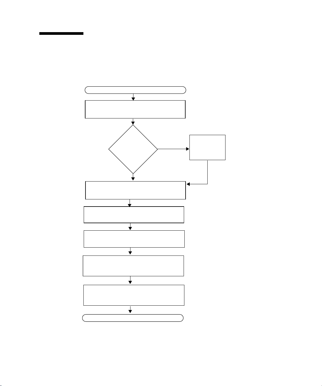
Planning the Installation Process
Use the following flowchart as a process tool to assist you with installation of the
Sun Fire X2100 Server.
START
Unpack the server and familiarize yourself
with the server features.
Install optional
components?
No
(Optional) Mount the server in a rack.
Connect the server and external device
cables.
Power on the server.
Install the operating system or configure the
preinstalled operating system.
Yes
See “Package Contents Inventory” on page 4.
Install
optional
components
See “Installing the Server Into a Rack With
Optional Slide-Rails” on page 4.
See “Cabling the Server” on page 18.
See“Powering On the Server” on page 21.
See “Setting Up or Installing the Operating
System” on page 22.
To install additional
components, see the Sun Fire
X2100 Server User Guide or
.
the component documentation.
Install the supplemental drivers from the Sun
Fire X2100 Server Supplemental CD.
READY TO WORK!
FIGURE 1-1 Sun Fire X2100 Server Installation Process
See “Installing other Operating Systems and
Drivers” on page 24.
Chapter 1 System Setup 3

Package Contents Inventory
Carefully unpack all server components from the packing cartons. The following
items should be packaged with the Sun Fire X2100 Server:
■ Sun Fire X2100 Server
■ Sun Fire X2100 Server documentation
■ Sun Fire X2100 Server Setup Guide
■ Sun Fire X2100 Server Release Notes
■ Important Safety Information for Sun Hardware Systems
■ Sun Binary Code License
■ Sun Fire X2100 Server Supplemental CD (includes drivers and diagnostics
software)
■ Optional rackmount kit
The optional power cable, keyboard, and mouse are packaged separately from the
other items.
Installing the Server Into a Rack With Optional Slide-Rails
Perform the procedures in this section, in the order they are listed, to install your
server into a four-post rack using the orderable slide-rail options These slide-rails
are compatible with a wide range of equipment racks that meet the following
standards:
■ Four-post structure (mounting at both front and rear). Two-post racks are not
compatible.
■ Rack horizontal opening and unit vertical pitch conforming to ANSI/EIA 310-D-
1992 or IEC 60927 standards.
■ Distance between front and rear mounting planes between 610 mm and 915 mm
(24 inches to 36 inches).
■ Clearance depth (to front cabinet door) in front of front rack mounting plane at
least 25.4 mm (1 inch).
■ Clearance depth (to rear cabinet door) behind front rack mounting plane at least
800 mm (31.5 inches), or 700 mm (27.5 inches), without cable management arm.
4 Sun Fire X2100 Server Setup Guide • September 2005
■ Clearance width (between structural supports and cable troughs) between front
and rear mounting planes at least 456 mm (18 inches).
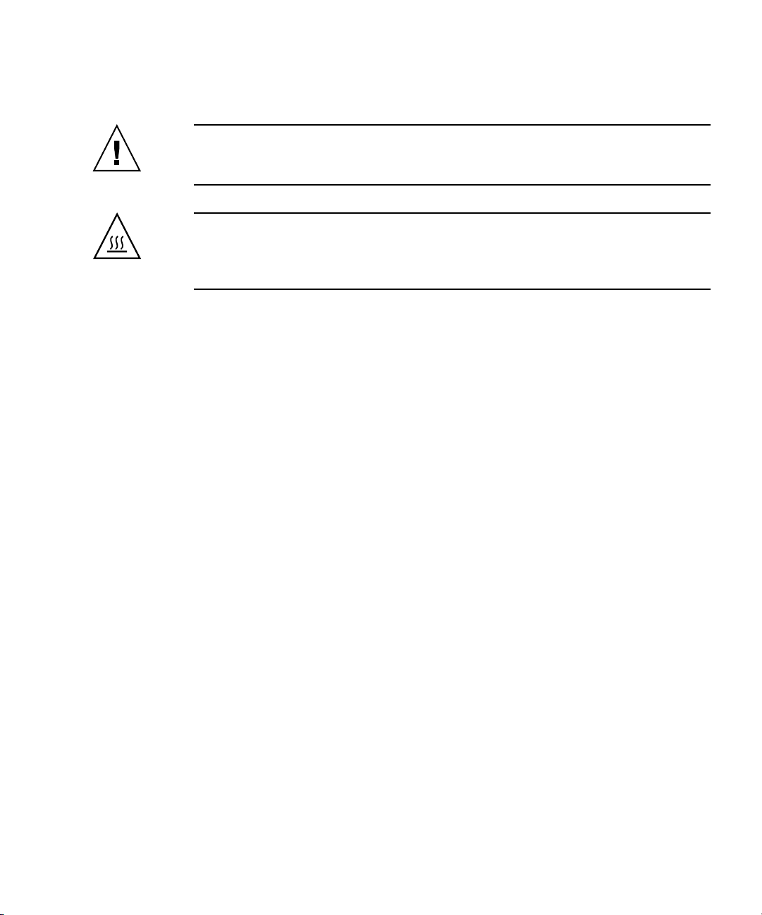
Caution – Always load equipment into a rack from the bottom up so that it will not
become top-heavy and tip over. Deploy your rack’s anti-tilt bar to prevent the rack
from tipping during equipment installation.
Caution – Ensure that the temperature in the rack does not exceed the server’s
maximum ambient rated temperatures. Consider the total airflow requirements of all
equipment installed in the rack, to ensure that the equipment is operated within its
specified temperature range.
Disassembling the Slide-Rails Before Installation
Use this procedure to remove the mounting brackets from the slide-rail assemblies.
1. Unpack the slide-rails.
2. Locate the slide-rail lock at the front of one of the slide-rail assemblies, as shown
in
FIGURE 1-2.
3. Squeeze and hold the tabs at the top and bottom of the lock while you pull the
mounting bracket out of the slide-rail assembly, until it reaches the stop.( See
FIGURE 1-2.
4. Pull the mounting bracket release button toward the front of the mounting
bracket, as shown in
FIGURE 1-2, and simultaneously withdraw the mounting
bracket from the slide-rail assembly.
5. Repeat for the remaining slide-rail assembly.
Chapter 1 System Setup 5
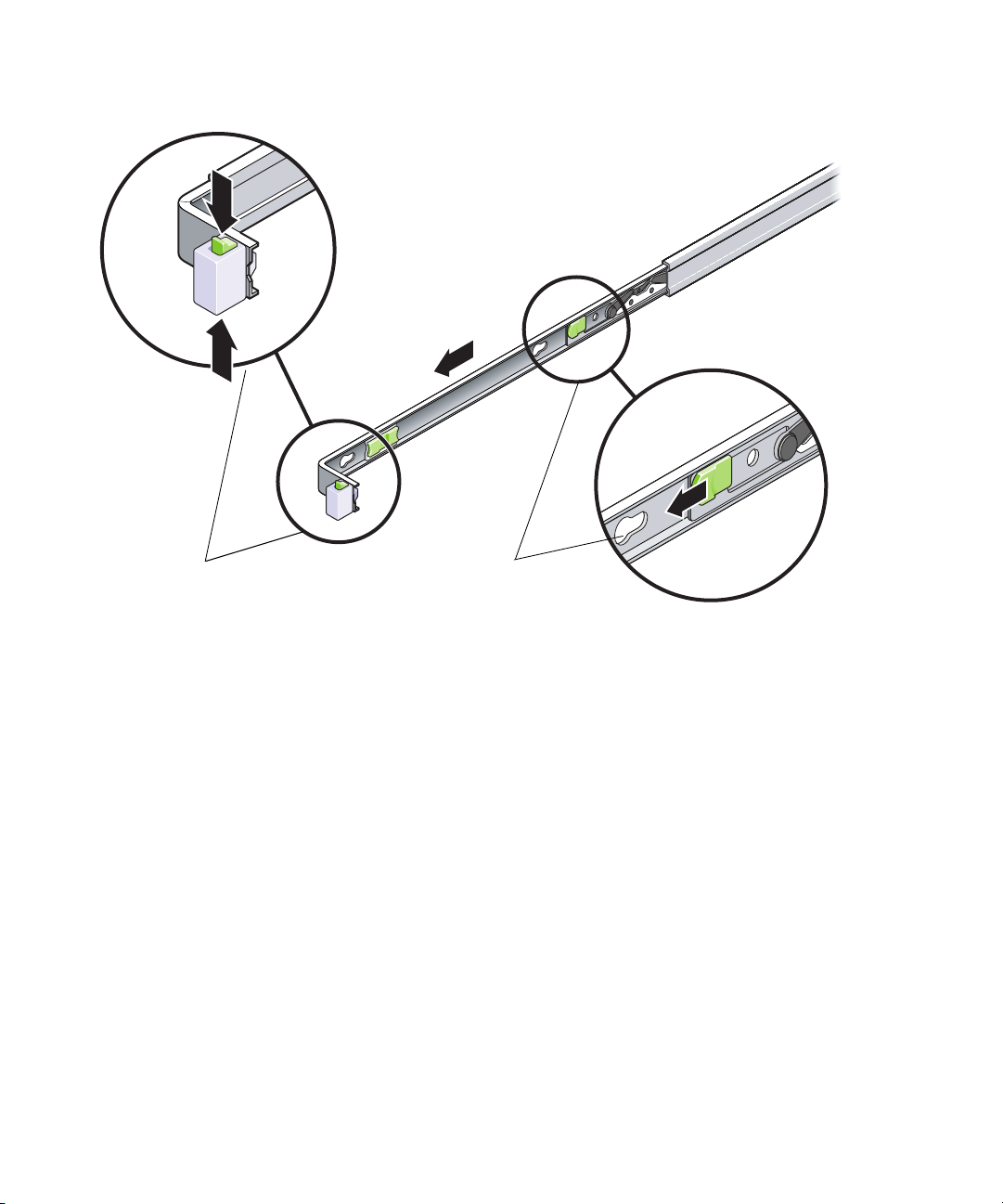
Slide-rail lock
Mounting bracket
release button
FIGURE 1-2 Disassembling the Slide-Rail Before Installation
6 Sun Fire X2100 Server Setup Guide • September 2005
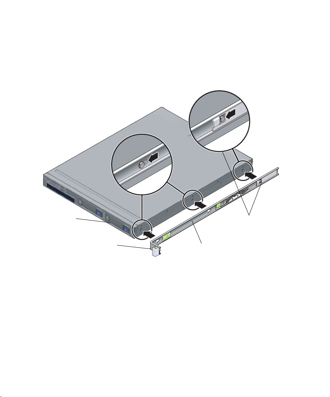
Installing the Mounting Brackets Onto the Server
Use this procedure to install the mounting brackets onto the sides of the server.
1. Position a mounting bracket against the chassis so that the slide-rail lock is at the
server front, and the three keyed openings on the mounting bracket are aligned
with the three locating pins on the side of the chassis.
Chassis front
Slide-rail lock
FIGURE 1-3 Aligning the Mounting Bracket With the Server Chassis
Mounting bracket
1. With the heads of the three chassis locating pins protruding though the three
keyed openings in the mounting bracket, pull the mounting bracket toward the
front of the chassis until the mounting-bracket clip locks into place with an
audible click. (See
FIGURE 1-3.)
2. Verify that the rear locating pin has engaged the mounting-bracket clip. (See
FIGURE 1-3.)
3. Repeat to install the remaining mounting bracket on the other side of the server.
Mounting-bracket clip
Chapter 1 System Setup 7

Attaching the Slide-Rail Assemblies to the Rack
Use this procedure to install the slide-rail assemblies to the rack.
1. Position a slide-rail assembly in your rack so that the brackets at each end of the
slide-rail assembly are on the outside of the front and rear rack posts. (See
FIGURE 1-4.)
2. Attach the slide-rail assembly to the rack posts, but do not tighten the screws
completely.
The method used to attach the slide-rails varies depending on the type of rack:
■ If your rack has threaded mounting holes in the rack posts, first determine
whether the threads are metric or standard, then insert the correct mounting
screws through the slide-rail brackets and into the threaded holes.
■ If your rack does not have threaded mounting holes, insert the mounting screws
through both the slide-rail brackets and rack posts, then secure them with the
caged nuts.
Rack post
Slide-rail assembly
bracket on outside
of rack post
Slide-rail
assembly
FIGURE 1-4 Slide-Rail Assembly Mounting to Rack Post
8 Sun Fire X2100 Server Setup Guide • September 2005

3. Repeat Step 1 and Step 2 for the remaining slide-rail assembly.
4. From the front of the rack, set the proper width of the rails with spacer. (See
FIGURE 1-5.)
FIGURE 1-5 Setting the Rail Width
5. Tighten the screws on the brackets.
6. Remove the spacer and confirm that the rails are attached tightly to the rack.
7. Repeat Step 4 through Step 6 for rear of the rack.
Chapter 1 System Setup 9

8. If available, extend the anti-tip foot at the bottom of the rack. (See FIGURE 1-6.)
FIGURE 1-6 Extending the Anti-tip Foot
Caution – If your rack does not have an anti-tip foot, there is some danger of the
rack tipping.
Installing the Server Into the Slide-Rail Assemblies
Use this procedure to install the server chassis, with mounting brackets, into the
slide-rail assemblies that are mounted to the rack.
Caution – This procedure requires a minimum of two people because of the weight
of the server. Attempting this procedure alone could result in equipment damage or
personal injury.
1. Push the slide-rails into the slide-rail assemblies in the rack as far as possible.
10 Sun Fire X2100 Server Setup Guide • September 2005

2. Raise the server so that the rear ends of the mounting brackets are aligned with
the slide-rail assemblies that are mounted in the equipment rack. (See
3. Insert the mounting brackets into the slide-rails, then push the server into the
rack until the mounting brackets encounter the slide-rail stops (approximately 12
inches, or 30 cm).
Slide-rail
release button
FIGURE 1-7.)
Mounting bracket
inserted into
slide-rail
Slide-rail
lock
Slide-rail
assembly
mounted on
rack post
FIGURE 1-7 Inserting the Server With Mounting Brackets Into the Slide-Rails
4. Simultaneously pull and hold the slide-rail release buttons on each mounting
bracket while you push the server into the rack. (See
FIGURE 1-7.) Continue
pushing until the slide-rail locks on the front of the mounting brackets engage the
slide-rail assemblies.
You will hear an audible click.
Caution – Verify that the server is securely mounted in the rack and that the slide-
rails locks are engaged with the mounting brackets before continuing.
Chapter 1 System Setup 11

Installing the Cable Management Assembly
Use this procedure to install an optional cable management assembly (CMA).
1. Unpack the CMA parts.
2. Take the CMA to the back of the equipment rack and ensure that you have
adequate room to work around the back of the server.
Note – References to “left” or “right” in this procedure assume that you are facing
the back of the equipment rack.
3. Locate the CMA rail extension and insert it into the left slide-rail until the
extension locks into place with an audible click. (See
The CMA rail extension might be taped to the CMA assembly.
FIGURE 1-8.)
Left slide-rail
CMA rail
extension
FIGURE 1-8 Inserting the CMA Rail Extension Into the Back of the Left Slide-Rail
12 Sun Fire X2100 Server Setup Guide • September 2005

CMA rail
extension
4. Verify that the CMA rail extension engages the slide-rail, as shown in FIGURE 1-9.
Left slide-rail
FIGURE 1-9 Detail of CMA Rail Extension Inserted Into the Left Slide-Rail
Note – Support the CMA in the remaining installation steps. Do not allow the
assembly to hang by its own weight until it is secured by all three of the attachment
points.
Chapter 1 System Setup 13

Right slide-rail
CMA mounting
bracket
5. Insert the CMA’s mounting bracket connector into the right slide-rail until the
connector locks into place with an audible click. (See
FIGURE 1-10.)
FIGURE 1-10 Inserting the CMA Mounting Bracket Into the Back of the Right Slide-Rail
14 Sun Fire X2100 Server Setup Guide • September 2005

6. Insert the right CMA slide-rail connector into the right slide-rail assembly until
the connector locks into place with an audible click. (See
FIGURE 1-11.)
Right sliderail assembly
CMA slide-rail
connector
FIGURE 1-11 Inserting CMA Slide-Rail Connector Into Back of Right Slide-Rail Assembly
Chapter 1 System Setup 15

7. Insert the right CMA slide-rail connector into the left slide-rail assembly until the
CMA extension
arm
(on left slide-rail)
connector locks into place with an audible click. (See
FIGURE 1-12.)
CMA arm connector
FIGURE 1-12 Connecting the CMA Arm to Rail Extension Connector
16 Sun Fire X2100 Server Setup Guide • September 2005

8. Position the cable hangers in the appropriate mounting holes in the CMA and
snap them into place. (See
For best results, place three hangers, evenly spaced, on the rear-facing side of the
CMA, and three on the side facing the server.
FIGURE 1-13.)
CMA arm
CMA cable hanger
FIGURE 1-13 Installing CMA Cable Hangers
Attaching and Routing Cables
Use this procedure to attach cables to your server and route them through the CMA.
1. Refer to “Cabling the Server” on page 18 for an illustration of the server back
panel ports and a procedure for installing cables to your server.
2. Install cables to your server, as required.
3. Route the cables through the CMA cable hangers.
Chapter 1 System Setup 17

Verifying Operation of the Slide-Rails and CMA
Use this procedure to ensure that the slide-rails and CMA are operating correctly.
Note – Two people are recommended for this procedure: one to move the server in
and out of the rack, and one to observe the cables and CMA.
1. Slowly pull the server out of the rack until the slide-rails reach their stops.
2. Inspect the attached cables for any binding or kinks.
3. Verify that the CMA extends fully from the slide-rails.
4. Push the server back into the rack, as described below.
When the server is fully extended, you must release two sets of slide-rail stops to
return the server to the rack:
a. The first set of stops are levers, located on the inside of each slide-rail, just
behind the back panel of the server. These levers are labeled “PUSH.” Push in
both levers simultaneously and slide the server toward the rack.
The server will travel approximately 15 inches (38 cm) and stop.
Verify that the cables and the CMA retract without binding before continuing.
b. The second set of stops are the slide-rail release buttons, located near the front
of each mounting bracket. See
the slide-rail release buttons and push the server completely into the rack until
both slide-rail locks engage.
FIGURE 1-7. Simultaneously push or pull both of
5. Adjust the cable hangers and CMA as required.
6. Continue with “Cabling the Server” on page 18.
Cabling the Server
Connect the server and external devices in this order (See FIGURE 1-14):
1. Connect the server power cord to a grounded electrical outlet.
2. Connect the keyboard and mouse to the USB connectors on the front or back
panel.
3. Connect the monitor cable to the onboard video connector
18 Sun Fire X2100 Server Setup Guide • September 2005

Note – Keyboard, mouse and video are optional.
4. Connect Ethernet cables to the platform gigabit connectors.
See “Interconnecting Servers” on page 3 for information on how to interconnect
servers and
connect them to a LAN.
5. Connect any additional external devices to the server ’s other connectors.
FIGURE 1-14 depicts the back panel of the Sun Fire X2100 Server.
12
FIGURE 1-14 Back Panel
TABLE 1-1 Back Panel
Label Connector/Slot/LED Label Connector/Slot
1 Power connector 6 Onboard HD15 video connector
2 Locate LED 7 Ethernet connectors (2)
3 Service indicator LED 8 PCI EXPRESS x8 slot
4 Power LED 9 USB connectors (4)
5 Serial connector 10
8734 5 6
SERIAL
9
Chapter 1 System Setup 19

Interconnecting Servers
FIGURE 1-15 shows how to connect multiple servers, using the platform Ethernet
connectors. LAN-1 can only be used for connecting to the internet. Remote server
management is directed over LAN-2 if you have the optional service processor (SP)
card installed.
= Ethernet (LAN)
connectors
LAN-1
Server
Server
Server
FIGURE 1-15 Interconnecting Servers
LAN-2
LAN-1
LAN-2
LAN-1
LAN-2
External LANs
Internet
20 Sun Fire X2100 Server Setup Guide • September 2005

Powering On the Server
Tip – If you are installing optional internal components such as additional memory
DIMMs, PCI cards, optical drives, or hard drives, install those components before
you power on the server. If you are not installing optional components, you are
ready to power on the server.
1. Ensure that a grounded AC power cord is plugged into the AC power connector
on the rear of the server and into an AC power outlet. (See
FIGURE 1-16.)
2. Press and release the server Power button on the front panel. (See
3. After several seconds, verify that the power-indicator LED next to the Power
button lights.
The power-indicator LED lights after the server begins the internal booting process.
See
4. (Optional) Press the Locate button on the front of the server to activate the locate
LEDs on the front and back of the server.
The locate LED will help you to locate the server in a rack configuration.
5. Continue with software setup tasks as described in “Setting Up or Installing the
Operating System” on page 22.
21345 67
.
FIGURE 1-16 Front Panel
TABLE 1-2 Front Panel
FIGURE 1-16.)
FIGURE 1-16 for location of the power-indicator LED.
HDD1 HDD2
Label Button/LED/Port Label Button/LED/port
1 Locate button/LED 5 USB ports (2)
2 Service indicator LED 6 DVD drive (optional)
3 Power LED 7 Hard disk drives (1 or 2 optional)
4 Power button
Chapter 1 System Setup 21

Setting Up or Installing the Operating System
If your server has at least one hard drive installed, the server will have the Solaris 10
Operating System preinstalled.
■ If you plan to run Solaris 10 Operating System on your server, see “Solaris 10
Operating System Setup” on page 22.
■ If you plan to install another operating system see “Installing other Operating
Systems and Drivers” on page 24.
Solaris 10 Operating System Setup
To set up the preinstalled Solaris 10 Operating System, do the following:
1. Gather the information shown in
Your system administrator (SA) should provide you with information specific to
your site before you begin. Some of the information
network—check with your SA. Use a copy of
that you might need to collect before setting up the Solaris Operating System.
TABLE 1-3.
might be available on your
TABLE 1-3 to write down the information
22 Sun Fire X2100 Server Setup Guide • September 2005

TABLE 1-3 Information for Preinstalled Solaris 10 Setup
Setup Window Explanation and Notes Your Information
Select Language
Native language and locale to use for the server.
and Locale
Host Name A name to give the server.
Network
Connectivity
Network or stand-alone server protocols. A system
administrator might be required to complete this section.
Note: Depending on how you answer and what
(IP Address)
information is provided by your network, you might also
be prompted for the server’s IP address.
Security Settings Security settings and protocols.
Name Service Name service to use: NIS+, NIS, DNS, LDAP, or None.
Note: This window is not displayed if the server is not
connected to a network.
Domain Name NIS or NIS+ domain for this server.
Note: This window is not displayed if the server is not
using the NIS or NIS+ service.
Name Server/
Subnet/
Subnet Mask
Name server (specify the server or have the server find one
on a local subnet).
Note: This window is not displayed if the server is not
connected to a network.
Note: Depending on how you answer and what
information is provided by your network, you might also
be prompted for:
- The subnet for the server
- The subnet mask for the server
Time Zone Local time zone (select by geographic region, GMT offset,
or a time zone file).
Date and Time Current date and time (accept the default or enter the
current date and time).
Root Password Root (superuser) password for the server.
Chapter 1 System Setup 23

2. Follow the system prompts to configure the operating system.
3. Install the networking and sound drivers from the Sun Fire X2100 Server
Supplemental CD.
You can also access these drivers from:
http://sun.com/servers/entry/x2100/downloads.html
Instructions for installing the drivers are available in the Sun Fire X2100 Server
Getting Started Guide, 819-3720-xx, available at:
http://www.sun.com/products-n-solutions/
hardware/docs/Servers/Workgroup_Servers/x2100/index.html
Installing other Operating Systems and Drivers
If you plan to install an operating system (OS) on your Sun Fire X2100 Server system
other than the Solaris 10 Operating System, install the OS at this time. You will need
to remove the Solaris 10 OS in order to do this.
The following sources of information can help you with installing additional
operating systems on the Sun Fire X2100 Server:
■ Information on removing the existing operating system, installing additional
drivers, and installing another operating system is in the Sun Fire X2100 Server
Getting Started Guide, 819-3720-xx, available at:
http://www.sun.com/products-n-solutions/
hardware/docs/Servers/Workgroup_Servers/x2100/index.html
■ Drivers for supported operating systems are available on the Sun Fire X2100
Server Supplemental CD included with your system and can also be downloaded
from:
http://sun.com/servers/entry/x2100/downloads.html
■ The most recent list of operating systems supported for Sun Fire X2100 Server can
be found on the product web site at:
http://sun.com/servers/entry/x2100/
24 Sun Fire X2100 Server Setup Guide • September 2005

CHAPTER
2
Setup Troubleshooting
This chapter contains information to help you troubleshoot minor server problems.
This chapter includes information on the following topics:
■ “Setup Troubleshooting for the Sun Fire X2100 Server” on page 26.
■ “Technical Assistance” on page 28
25

Setup Troubleshooting for the Sun Fire X2100 Server
If you experience problems while setting up your server, refer to the troubleshooting
information in
TABLE 2-1 Troubleshooting Procedures
Problem Possible solution
Server powers on,
but the monitor does
not.
CD or DVD does not
eject from the media
tray when you press
the Eject button.
No video displays
on the monitor
screen.
Server does not
power on when the
front panel Power
button is pressed.
TABLE 2-1.
• Is the Power button for the monitor turned on?
• Is the monitor power cord connected to a wall outlet?
• Does the wall outlet have power? Test by plugging in another
device.
• Move the mouse or press any key on the keyboard. The drive
might be in the low-power mode.
• Use the utility software installed on your server to eject the CD.
• Is the monitor cable attached to the graphics accelerator?
• Does the monitor work when connected to another system?
• If you have another monitor, does it work when connected to the
original system?
• Verify that the BIOS settings are correct.
Keep notes on the following situations in case you need to call
service:
• Is the Power button LED illuminated on the front of the system?
(Ensure that the power cord is connected to the system and to a
grounded power receptacle.)
• Does the wall outlet have power? Test by plugging in another
device.
• Does the system beep when the system is powered on? (Ensure
that the keyboard is plugged in).
• Test with another keyboard that you know is functional. Does the
system beep when you connect the keyboard and power on the
system?
• Does the monitor sync within 5 minutes after power on? (The
green LED on the monitor stops flashing and remains
illuminated.)
26 Sun Fire X2100 Server Setup Guide • September 2005

TABLE 2-1 Troubleshooting Procedures (Continued)
Problem Possible solution
Keyboard or mouse
does not respond to
actions
• Verify that the mouse and keyboard cables are connected to the
on-board USB 2.0 connectors on the server.
• Verify that the server is powered on and the front Power LED is
illuminated.
Server appears to be
in low-power mode,
but the Power
button LED does not
The power-indicator LED only blinks when all server components
are in low-power mode. A tape drive might be connected to your
server. Because tape drives do not enter low-power mode, the
power-indicator LED does not blink.
blink.
Hung or frozen
server: No response
from mouse or
keyboard or any
application.
Try to access your system from a different server on the network.
1. From a terminal window, type: ping hostname
2. Is no response, remotely log in from another system using
telnet or rlogin, and ping the system again.
3. Attempt to kill processes until the system responds.
If the above procedures do not work:
1. Press the Power button to power off the system.
2. Wait 20 to 30 seconds and power on the system.
Note – For additional troubleshooting information, see Sun Fire X2100 Server User
Guide.
Chapter 2 Setup Troubleshooting 27

Technical Assistance
If the troubleshooting procedures in this chapter fail to solve your problem, use
TABLE 2-2 to collect information that you might need to communicate to the support
personnel.
technical support.
TABLE 2-2 System Information Need for Support
System Configuration Information Needed Your Information
Sun service contract number
System model
Operating environment
System serial number
Peripherals attached to the system
Email address and phone number for you and a
secondary contact
Street address where the system is located
Superuser password
Summary of the problem and the work being done
when the problem occurred
Other Useful Information
IP address
Server name (System host name)
Network or internet domain name
Proxy server configuration
TABLE 2-3 lists the Sun web sites and telephone numbers for additional
28 Sun Fire X2100 Server Setup Guide • September 2005

TABLE 2-3 Sun Web Sites and Telephone Numbers
Server Documents and Support Resources URL or Telephone Number
PDF files for all the current Sun Fire X2100 Server
http://www.sun.com/documentation/
documents.
Solaris™ and other software documents. This web
http://docs.sun.com/documentation/
site has full search capabilities.
Discussion and troubleshooting forums. http://supportforum.sun.com/
Support, diagnostic tools, and alerts for all Sun
http://www.sun.com/bigadmin/
products.
SunSolve
web site. Contains links to software
http://www.sunsolve.sun.com/handbook_pub/
SM
patches. Lists some system specifications,
troubleshooting and maintenance information, and
other tools.
SM
SunService
Lists international telephone numbers for
SunService Support.
Warranty and contract support contacts. Links to
support phone numbers. 1-800-872-4786 (1-800-USA-4Sun) Select Option 1
http://www.sun.com/service/contacting/
solution.html
http://www.sun.com/service/online/
other service tools.
Warranties for every Sun product. http://www.sun.com/service/support/warranty
Chapter 2 Setup Troubleshooting 29

30 Sun Fire X2100 Server Setup Guide • September 2005
 Loading...