


Sun Fire™T1000 Server
Installation Guide
Sun Microsystems, Inc.
www.sun.com
Part No. 819-3247-11
July 2006, Revision A
Submit comments about this document at: http://www.sun.com/hwdocs/feedback

Copyright 2006Sun Microsystems,Inc., 4150Network Circle, SantaClara, California95054, U.S.A.All rightsreserved.
Sun Microsystems,Inc. hasintellectual property rightsrelating totechnology thatis describedin thisdocument. Inparticular, andwithout
limitation, theseintellectual propertyrights mayinclude oneor more ofthe U.S.patents listedat http://www.sun.com/patentsand oneor
more additionalpatents orpending patentapplications inthe U.S.and inother countries.
This documentand theproduct towhich itpertains are distributedunder licensesrestricting theiruse, copying,distribution, and
decompilation. Nopart ofthe productor ofthis documentmay bereproducedin anyform byany meanswithout priorwritten authorizationof
Sun andits licensors,if any.
Third-party software, includingfont technology,is copyrightedand licensedfrom Sun suppliers.
Parts ofthe productmay bederived from BerkeleyBSD systems,licensed fromthe Universityof California.UNIX isa registered trademarkin
the U.S.and inother countries,exclusively licensedthrough X/OpenCompany, Ltd.
Sun, SunMicrosystems, theSun logo,Java, docs.sun.com,OpenBoot, SunFire, and Solaris are trademarksor registered trademarksof Sun
Microsystems, Inc.in theU.S. andin othercountries.
All SPARCtrademarks areused underlicense andare trademarks or registered trademarksof SPARCInternational, Inc.in theU.S. andin other
countries. Productsbearing SPARCtrademarks are basedupon anarchitecture developed by Sun Microsystems,Inc.
The OPENLOOK andSun™ GraphicalUser Interfacewas developedby SunMicrosystems, Inc.for itsusers andlicensees. Sunacknowledges
the pioneeringefforts ofXerox in researchingand developingthe conceptof visualor graphicaluser interfacesfor thecomputer industry.Sun
holds anon-exclusive licensefrom Xerox tothe XeroxGraphical UserInterface, whichlicense alsocovers Sun’slicensees whoimplement OPEN
LOOK GUIsand otherwisecomply withSun’s writtenlicense agreements.
U.S. GovernmentRights—Commercial use.Government usersare subject to the Sun Microsystems, Inc.standard licenseagreement and
applicable provisionsof theFAR andits supplements.
DOCUMENTATION IS PROVIDED "AS IS" AND ALL EXPRESS OR IMPLIED CONDITIONS, REPRESENTATIONS AND WARRANTIES,
INCLUDING ANYIMPLIED WARRANTY OFMERCHANTABILITY, FITNESSFOR A PARTICULAR PURPOSEOR NON-INFRINGEMENT,
ARE DISCLAIMED, EXCEPT TO THE EXTENT THAT SUCH DISCLAIMERS ARE HELD TO BE LEGALLY INVALID.
Copyright 2006Sun Microsystems,Inc., 4150Network Circle, SantaClara, Californie95054, Etats-Unis.Tous droitsréservés.
Sun Microsystems,Inc. ales droits depropriété intellectuelsrelatants à la technologie qui est décritdans ce document. Enparticulier,et sansla
limitation, cesdroits depropriété intellectuels peuvent inclure unou plusdes brevetsaméricains énumérésà http://www.sun.com/patents et
un oules brevetsplus supplémentaires oules applicationsde breveten attentedans lesEtats-Unis etdans lesautrespays.
Ce produitou documentest protégé parun copyrightet distribuéavec deslicences quien restreignent l’utilisation,la copie,la distribution,et la
décompilation. Aucunepartie dece produitou documentne peutêtre reproduite sousaucune forme,par quelquemoyen quece soit,sans
l’autorisation préalableet écritede Sunet deses bailleursde licence,s’il yen a.
Le logicieldétenu pardes tiers,et quicomprend latechnologie relative auxpolices decaractères, estprotégépar uncopyright etlicencié pardes
fournisseurs deSun.
Des partiesde ceproduit pourront êtredérivées dessystèmes BerkeleyBSD licenciéspar l’Universitéde Californie.UNIX estune marque
déposée auxEtats-Unis etdans d’autrespays etlicenciée exclusivementpar X/OpenCompany, Ltd.
Sun, SunMicrosystems, lelogo Sun,Java, docs.sun.com,OpenBoot, SunFire, et Solaris sont desmarques defabrique oudes marquesdéposées
de SunMicrosystems, Inc.aux Etats-Uniset dansd’autres pays.
Toutes lesmarques SPARC sont utilisées sous licence et sont des marques defabrique oudes marquesdéposées deSPARC International,Inc.
aux Etats-Uniset dansd’autres pays.Les produits portantles marquesSPARC sont baséssur unearchitecture développéepar Sun
Microsystems, Inc.
L’interfaced’utilisation graphiqueOPEN LOOKet Sun™a étédéveloppée parSun Microsystems, Inc.pour sesutilisateurs etlicenciés. Sun
reconnaît lesefforts de pionniers de Xeroxpour larecherche et le développement du concept des interfaces d’utilisation visuelle ou graphique
pour l’industriede l’informatique.Sun détientune licensenon exclusivede Xeroxsur l’interfaced’utilisation graphiqueXerox,cette licence
couvrant égalementles licenciéesde Sunqui mettenten placel’interface d’utilisation graphiqueOPEN LOOKet quien outrese conforment
aux licencesécrites deSun.
LA DOCUMENTATION EST FOURNIE "EN L’ÉTAT" ET TOUTES AUTRES CONDITIONS, DECLARATIONS ET GARANTIES EXPRESSES
OU TACITES SONT FORMELLEMENTEXCLUES, DANSLA MESUREAUTORISEE PARLA LOIAPPLICABLE, YCOMPRIS NOTAMMENT
TOUTE GARANTIE IMPLICITE RELATIVE A LA QUALITE MARCHANDE, A L’APTITUDE A UNE UTILISATION PARTICULIERE OU A
L’ABSENCE DE CONTREFAÇON.
Please
Recycle

Contents
Preface xi
1. Preparing for Installation 1
Tools Needed 2
Shipping Kit Inventory List 2
Optional Components 3
Installation Overview 3
Slide Rail Assembly Notes 5
Cable Management Notes 8
Data Port and Cabling Notes 9
Port Locations 9
Cabling Notes 9
Safety Precautions 10
2. Installing the Sun Fire T1000 Server 11
Rackmount Kit 11
Installing the Server in a Rack 12
▼ To Install the Mounting Brackets 12
▼ To Install the Slide Rails 15
▼ To Install the Server in the Rack 19
iii

▼ To Install the Cable Management Bracket 20
Removing the Server From the Rack for Service 20
Connecting the Server Cables 20
▼ To Connect the SC Serial Management Port 21
▼ To Connect the SC Network Management Port 22
▼ To Connect the Ethernet Network Cables 22
TTYA Serial Port 22
▼ To Connect the AC Power Cables to the Server 23
3. Powering On the System 25
Powering On the System for the First Time 25
▼ To Power On the System for the First Time 26
Logging In To the ALOM-CMT System Controller 28
▼ To Log In To the System Controller Usingthe Serial Management Port 29
▼ To Log In To the System Controller Using the Network Management
Port 30
▼ To Configure the System Controller Network Management Port 30
▼ To Reset the System Controller 33
Using the ALOM-CMT System Controller for Common Operations 35
▼ To Initiate the Power On Sequence 35
▼ To Connect to the System Console 35
Example of a Normal System Initialization 36
Booting the Solaris Operating System 38
▼ To Boot the Solaris Operating System 38
▼ (Optional) To Reset the System 39
▼ To Power Cycle the System 39
A. Updating the Sun Fire T1000 Firmware 41
Flash Image Overview 41
Updating the Firmware 41
iv Sun Fire T1000 Server Installation Guide • July 2006

▼ To Update the Firmware 42
B. Selecting a Boot Device 45
Connecting the Network Interface to the Network 45
▼ To Connect the Network Interface to the Network 45
C. Configuring the Network Management Port 47
▼ To Configure the System Controller Network Management Port 47
Index 51
Contents v

vi Sun Fire T1000 Server Installation Guide • July 2006

Figures
FIGURE 1-1 Sun Fire T1000 Server 1
FIGURE 1-2 Slide Rail Assembly 6
FIGURE 1-3 Mounting Bracket Locks 7
FIGURE 1-4 Cable Management Bracket 8
FIGURE 1-5 Locations of Ports and Connectors on the Rear Panel 9
FIGURE 2-1 Unlocking the Slide Rail Assembly 12
FIGURE 2-2 Mounting Bracket Release Button 13
FIGURE 2-3 Attaching a Mounting Bracket to the Chassis 14
FIGURE 2-4 Captive Screws on the Slide Rail 15
FIGURE 2-5 Using the Extension Bracket 16
FIGURE 2-6 Mounting the Slide Rail 17
FIGURE 2-7 Using the Slide Rail Spacing Tool to Adjust the Distance Between the Slide Rails 18
FIGURE 2-8 Mounting the Chassis on the Slide Rails 19
FIGURE 2-9 Rear Panel Connectors 21
FIGURE 2-10 System Controller Serial and Network Ports, Rear of Chassis 21
FIGURE 2-11 Serial Port (TTYA) 22
FIGURE 3-1 AC Connector 27
vii

viii Sun Fire T1000 Server Installation Guide • July 2006

Tables
TABLE 1-1 Ethernet Connection Transfer Rates 10
TABLE 3-1 Sun Fire T1000 Device List 37
ix

x Sun Fire T1000 Server Installation Guide • July 2006

Preface
This guide provides instructions, background information, and reference material to
help you install the Sun Fire™ T1000 server.
Instructions for installation in the document assume that a system administrator is
experienced with the Solaris™ Operating System (Solaris OS).
Note – All internal components must be installed by qualified service technicians
only.
How This Document Is Organized
This document is organized in the following way:
Chapter 1 provides an overview of the Sun Fire T1000 server installation process.
Chapter 2 provides instructions for installing the Sun Fire T1000 server into a rack.
Chapter 3 provides instructions for configuring and powering on the server, and for
installing additional software.
Appendix A provides instructions for updating the system controller firmware and
the host firmware.
Appendix B provides instructions for selecting a boot device.
Appendix C provides configuration instructions for servers that use an earlier
version of firmware than Sun system firmware 6.2.
xi

Using UNIX Commands
This document might not contain information about basic UNIX®commands and
procedures such as shutting down the system, booting the system, and configuring
devices. Refer to the following for this information:
■ Software documentation that you received with your system
■ Solaris Operating System documentation, which is at:
http://docs.sun.com
Shell Prompts
Shell Prompt
C shell machine-name%
C shell superuser machine-name#
Bourne shell and Korn shell $
Bourne shell and Korn shell superuser #
Typographic Conventions
*
Typeface
AaBbCc123 The names of commands, files,
AaBbCc123 What you type, when contrasted
AaBbCc123 Book titles, new words or terms,
* The settings on your browser might differ from these settings.
xii Sun Fire T1000 Server Installation Guide • July 2006
Meaning Examples
and directories; on-screen
computer output
with on-screen computer output
words to be emphasized.
Replace command-line variables
with real names or values.
Edit your.login file.
Use ls -a to list all files.
% You have mail.
su
%
Password:
Read Chapter 6 in the User’s Guide.
These are called class options.
Yo u must be superuser to do this.
To delete a file, type rm filename.

Sun Fire T1000 Server Documentation
You can view and print the following manuals from the Sun™ documentation web
site at http://www.sun.com/documentation
Title Description Part Number
Sun Fire T1000 Server Site Planning Guide Site planning information for the server 819-3749
Sun Fire T1000 Server Product Notes Late-breaking information about the server. The latest
notes are posted at:
http://www.sun.com/documentation
Sun Fire T1000 Server Getting Started
Guide
Sun Fire T1000 Server Overview Provides an overview of the features of this server 819-3245
Sun Fire T1000 Server Administration
Guide
Sun Fire T1000 Server Service Manual How to run diagnostics to troubleshoot your server
Advanced Lights Out Management
(ALOM) CMT Guide
Sun Fire T1000 Server Safety and
Compliance Guide
Information about where to find documentation to get
your system installed and running quickly
How to perform administrative tasks that are specific
to this server
and how to remove and replace parts
How to use the Advanced Lights Out Manager
(ALOM) CMT software on this server
Provides safety and compliance information that is
specific to this server
819-3246
819-3244
819-3249
819-3248
819-3250
(version 1.1)
819-6672
(version 1.2)
819-6674
Preface xiii

Documentation, Support, and Training
Sun Function URL
Documentation http://www.sun.com/documentation/
Support http://www.sun.com/support/
Training http://www.sun.com/training/
Third-Party Web Sites
Sun is not responsible for the availability of third-party web sites mentioned in this
document. Sun does not endorse and is not responsible or liable for any content,
advertising, products, or other materials that are available on or through such sites
or resources. Sun will not be responsible or liable for any actual or alleged damage
or loss caused by or in connection with the use of or reliance on any such content,
goods, or services that are available on or through such sites or resources.
Sun Welcomes Your Comments
Sun is interested in improving its documentation and welcomes your comments and
suggestions. You can submit your comments by going to:
http://www.sun.com/hwdocs/feedback
Please include the title and part number of your document with your feedback:
Sun Fire T1000 Server Installation Guide, part number 819-3247-11
xiv Sun Fire T1000 Server Installation Guide • July 2006
CHAPTER
1
Preparing for Installation
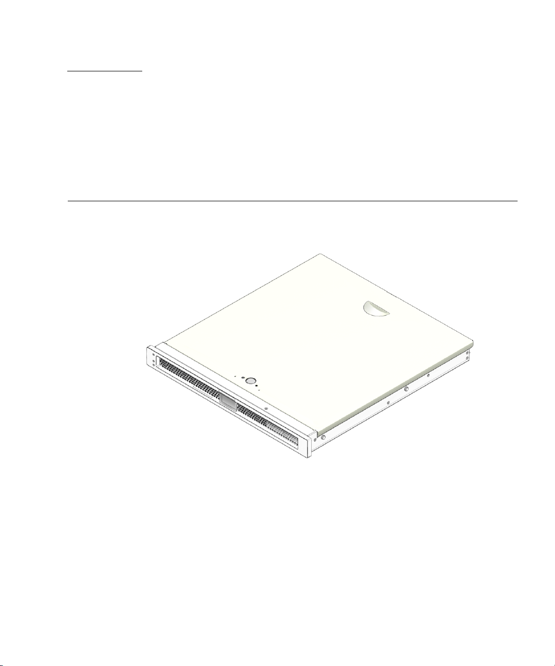
This chapter describes the Sun Fire T1000 server installation, and provides
background information about the installation procedures that begin in Chapter 2.
FIGURE 1-1 Sun Fire T1000 Server
This chapter contains these topics:
■ “Tools Needed” on page 2
■ “Shipping Kit Inventory List” on page 2
■ “Optional Components” on page 3
■ “Installation Overview” on page 3
■ “Slide Rail Assembly Notes” on page 5
■ “Cable Management Notes” on page 8
■ “Data Port and Cabling Notes” on page 9
■ “Safety Precautions” on page 10
1

Tools Needed
■ No. 2 Phillips screwdriver
■ ESD mat and grounding strap
Shipping Kit Inventory List
Standard components of Sun Fire T1000 server are installed at the factory. However,
if you ordered options such as additional memory or a PCI card, these are shipped
to you separately.
Note – Inspect the shipping carton for evidence of physical damage. If a shipping
carton appears damaged, request that the carrier’s agent be present when the carton
is opened. Keep all contents and packing material for the agent’s inspection.
Verify that you have received all the parts of your system:
■ Sun Fire T1000 server
■ Mounting rail assemblies (x2)
■ Mounting rail extension brackets (x2)
■ Package of mounting screws and nuts
■ Cable management bracket
■ Package of cable straps
■ Serial DB-9 connector to RJ-45 connector conversion cable
■ Documentation and software license
■ Any optional components that were ordered with your server
2 Sun Fire T1000 Server Installation Guide • July 2006

Optional Components
The standard components of the Sun Fire T1000 server are installed at the factory.
However, if you ordered options such as additional memory or a PCI card, these are
shipped separately. Install these components prior to installing the server in a rack.
If you ordered any other options that are not factory-installed, see the Sun Fire T1000
Server Service Manual for installation instructions.
Note – All internal components must be installed only by qualified service
technicians.
Caution – Electrostatic damage can permanently disable the system or require
repair by Sun service technicians. Place components on an antistatic surface, such as
an antistatic discharge mat, an antistatic bag, or a disposable antistatic mat. Wear an
antistatic grounding strap connected to a metal surface on the chassis when you
work on system components.
Note – The list of optional components can be updated without notice. Refer to the
Sun Store web site (http://store.sun.com) for the most current list of
components supported in the Sun Fire T1000 server.
Installation Overview
This installation guide provides procedures that must be performed in the following
order.
1. Verify that you have received all of the components that ship with your server.
See “Shipping Kit Inventory List” on page 2.
2. Gather configuration information for your system. See your system administrator
for specific details, including these parameters:
■ Gateway IP address
■ IP address for the system controller
■ Netmask
Chapter 1 Preparing for Installation 3

3. Install any optional Sun components shipped with your system. If you have
purchased other optional components such as additional memory, install them
prior to mounting the server in a rack. See “Optional Components” on page 3.
4. Mount the server into a rack or cabinet. See “To Install the Server in the Rack” on
page 19.
Note – In the rest of this document, the term rack means either an open rack or a
closed cabinet.
5. Connect the server to a serial terminal or a terminal emulator (PC or workstation)
to display system messages. See “Powering On the System for the First Time” on
page 25.
Tip – The serial terminal or a terminal emulator should be connected before you
connect the power cables. As soon as AC power is connected to the system, the
system controller immediately powers on and runs diagnostics. Diagnostic test
failures will be printed on the serial terminal. For more information, refer to the
Advanced Lights Out Management (ALOM) CMT v1.2 Guide.
6. Connect the data cables to the server, but do not connect the AC power cable yet.
See “Connecting the Server Cables” on page 20.
7. Connect the AC power cable to the server and examine the display for any error
messages. See “Powering On the System for the First Time” on page 25.
Caution – There is a potential for electric shock if the server and related equipment
are not properly grounded.
Note – The system controller (SC) runs on the 3.3v standby voltage. As soon as AC
power is connected to the system, the system controller immediately powers on,
runs diagnostics, and initializes the ALOM-CMT firmware.
8. After the system controller boots, access the ALOM-CMT command-line interface
through the serial management port. See “To Log In To the System Controller
Using the Serial Management Port” on page 29.
9. Configure the SC network management port. See “To Configure the System
Controller Network Management Port” on page 30.
10. Enable the new configuration by resetting the system controller. See “To Reset
the System Controller” on page 33.
4 Sun Fire T1000 Server Installation Guide • July 2006

11. Power on the server using the ALOM-CMT software. See “To Initiate the Power
On Sequence” on page 35.
12. Configure the Solaris OS. See “To Boot the Solaris Operating System” on page 38.
The Solaris OS is preinstalled on the server. When you power on, you are
automatically guided through the Solaris OS configuration procedure. See “To
Boot the Solaris Operating System” on page 38.
13. Install any required patch or patches to the server.
Refer to the Sun Fire T1000 Server Product Notes for a list of the required patches.
14. (Optional) Load additional software from the Solaris media kit.
The Solaris media kit (sold separately) includes several CDs containing software
to help you operate, configure, and administer your server. Refer to the
documentation provided with the media kit for a complete listing of included
software and detailed installation instructions.
Slide Rail Assembly Notes
The rackmount kit has two slide rail assemblies. Each slide rail assembly can be
installed on either the right or left side of the rack.
A slide rail assembly consists of three main sections, a front section, a sliding rear
section, and a removable mounting bracket (
includes two extension brackets.
FIGURE 1-2). The rackmount kit also
Chapter 1 Preparing for Installation 5
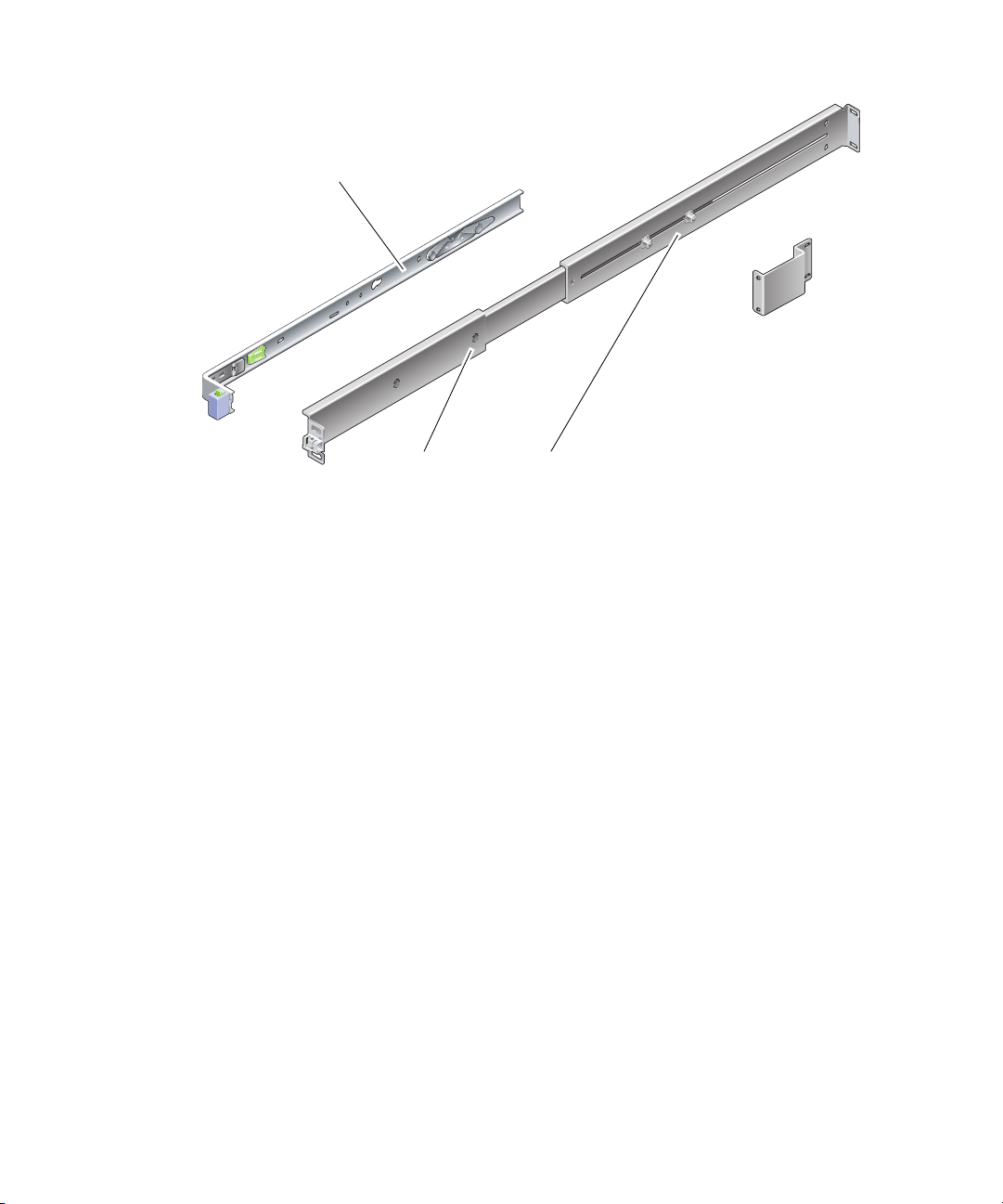
Mounting bracket
(shown removed)
Extension bracket
Front section
FIGURE 1-2 Slide Rail Assembly
Rear section
The slide rail assembly has the following features:
■ The front and rear sections form the slide rail. The front and rear sections expand
to fit rack depths from 24 in. (610 mm) to 29.0 in. (737 mm).
■ Extension brackets are included in the mounting rail kit. The extension brackets
add 2.9 in. (73 mm) to the length of each slide rail.
■ The mounting bracket slides 13 in. (330 mm) out of the slide rail, then locks in
place. If you unlock the mounting bracket, it slides an additional 4 in. (100 mm)
before separating from the slide rail. The mounting brackets mount directly to the
sides of the Sun Fire T1000 chassis.
■ There are two locks on each Sun Fire T1000 mounting bracket (FIGURE 1-3). The
mounting bracket lock allows the mounting bracket to slide forward. The
mounting bracket release allows you to remove the mounting bracket from the
slide rail. You also use the release when pushing the mounting bracket into the
slide rail.
6 Sun Fire T1000 Server Installation Guide • July 2006
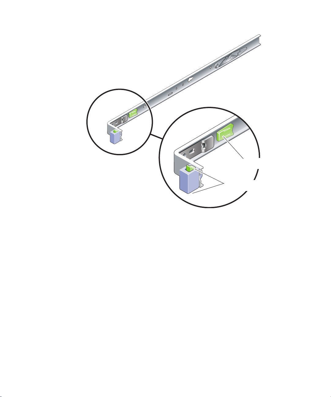
FIGURE 1-3 Mounting Bracket Locks
Mounting bracket release
Mounting bracket lock (2 buttons)
Chapter 1 Preparing for Installation 7

Cable Management Notes
A cable management bracket (FIGURE 1-4) is included in the Sun Fire T1000 slide rail
kit. The cable management bracket clips onto the slide rails. Use cable ties or cable
straps to attach cabling to the bracket.
FIGURE 1-4 Cable Management Bracket
8 Sun Fire T1000 Server Installation Guide • July 2006
Data Port and Cabling Notes
Port Locations
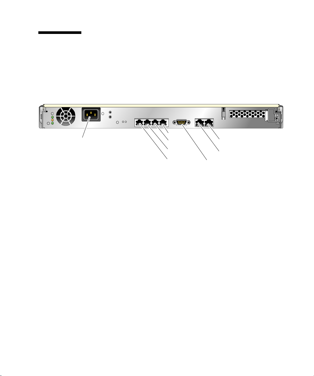
FIGURE 1-5 shows the ports on the Sun Fire T1000 server.
AC in
FIGURE 1-5 Locations of Ports and Connectors on the Rear Panel
NET3
NET2
NET1
NET0
SC network management port
SC serial management port
Serial port
Cabling Notes
The following list describes the server’s cable connections and ports:
■ Minimum cable connections for the Sun Fire T1000 system:
■ At least one system on-board Ethernet network connection (NET port)
■ System controller serial management port (SERIAL MGT port)
■ System controller network management port (NET MGT port)
■ Power cable
■ System controller (SC) management ports. There are two SC management ports
for use with the ALOM-CMT system controller.
■ The SC serial management port (labeled SERIAL MGT) uses an RJ-45 cable and
is always available. This is the default connection to the ALOM-CMT system
controller.
■ The SC network management port (labeled NET MGT) is the optional
connection to the ALOM-CMT system controller. See “To Configure the System
Controller Network Management Port” on page 30. The SC network
management port uses an RJ-45 cable for a 10/100BASE-T connection. This
port does not support connections to Gigabit networks.
See the Sun Fire T1000 Server Overview for more information.
Chapter 1 Preparing for Installation 9

■ Ethernet ports. The Sun Fire T1000 server Ethernet interfaces operate at 10 Mbps,
100 Mbps, and 1000 Mbps. The transfer rates for the Ethernet ports are given in
TABLE 1-1.
TABLE 1-1 Ethernet Connection Transfer Rates
Connection Type IEEE Terminology Transfer Rate
Ethernet 10BASE-T 10 Mbit/sec
Fast Ethernet 100BASE-TX 100 Mbits/sec
Gigabit Ethernet 1000BASE-T 1000 Mbit/sec
■ TTYA serial port. Use the Sun Fire T1000 DB-9 connector with a null modem
cable for serial devices. This port appears as ttya in Solaris OS and OpenBoot
PROM™ messages. This port is not connected to the SC serial management port.
■ AC power cables. As soon as the AC power cables are connected to the power
source, the server goes into standby mode and the ALOM-CMT system controller
initializes.
Tip – The serial terminal or a terminal emulator should be connected before you
connect the power cables. As soon as AC power is connected to the system, the
system controller immediately powers on and runs diagnostics. Diagnostic test
failures will be printed on the serial terminal. For more information, refer to the
Advanced Lights Out Management (ALOM) CMT v1.2 Guide.
Safety Precautions
Caution – Deploy the antitilt bar (if installing in a cabinet) before beginning the
installation.
10 Sun Fire T1000 Server Installation Guide • July 2006

CHAPTER
2
Installing the Sun Fire T1000 Server
This chapter provides instructions for installing the Sun Fire T1000 server in an open
rack or closed cabinet. This chapter contains the following sections:
■ “Rackmount Kit” on page 11
■ “Installing the Server in a Rack” on page 12
■ “Removing the Server From the Rack for Service” on page 20
■ “Connecting the Server Cables” on page 20
Note – Ensure that you have all of the parts before you begin the installation of the
server. See “Shipping Kit Inventory List” on page 2
Note – In this guide, references to left and right are from your viewpoint as you face
either the front or the rear of the system.
Rackmount Kit
The Sun Fire T1000 server rackmount kit includes two mounting slides, a slide
spacing tool, and a cable management bracket. The kit also includes two extension
brackets for use with racks up to 39.5 in. (1000 mm) in depth.
The mounting kit also includes an assortment of screws and nuts to fit various types
of racks. Extra screws and nuts are included.
11

Installing the Server in a Rack
▼ To Install the Mounting Brackets
1. Pull both mounting brackets completely out of their respective slide rails.
a. Simultaneously press and hold the upper and lower lock buttons of the slide
rail lock (
FIGURE 2-1).
FIGURE 2-1 Unlocking the Slide Rail Assembly
b. Pull the mounting bracket out until it stops.
c. Slide the mounting bracket release button to the left (
mounting bracket completely out of the slide rail.
12 Sun Fire T1000 Server Installation Guide • July 2006
FIGURE 2-2), then slide the

FIGURE 2-2 Mounting Bracket Release Button
2. Attach a mounting bracket to the right side of the Sun Fire T1000 chassis.
a. Position the mounting bracket against the server chassis (
FIGURE 2-3) so that the
slide rail lock is at the front and the two keyed openings on the mounting
bracket are aligned with the two locating pins on the side of the chassis.
Chapter 2 Installing the Sun Fire T1000 Server 13

FIGURE 2-3 Attaching a Mounting Bracket to the Chassis
b. With the heads of the two locating pins protruding though the two keyed
openings in the mounting bracket, slide the mounting bracket toward the front
of the chassis until the bracket locks into place with an audible click.
c. Verify that both locating pins are trapped in the keyed openings and that the
front locating pin has engaged the mounting bracket lock (
FIGURE 2-3).
3. Attach the second mounting bracket to the left side of the Sun Fire T1000 chassis.
14 Sun Fire T1000 Server Installation Guide • July 2006

▼ To Install the Slide Rails
1. Determine which rack hole numbers you will use when attaching the slide rails to
the rack posts.
Most racks have posts that are marked off by rack units (1.75 in. or 45 mm). The Sun
Fire T1000 server occupies one rack unit.
2. Determine which screws you will use to mount the slide rails.
■ If your rack has threaded mounting holes in the rack posts, determine whether
the threads are metric or standard. Select the appropriate screws from the package
included in the mounting kit.
■ If your rack does not have threaded mounting holes, the mounting screws go
through bracket and rack post, and are secured with a caged nut. Select the
appropriate screws and nuts from the package included in the mounting kit.
3. Loosen the two captive screws (
FIGURE 2-4) approximately a quarter-turn on each
slide rail.
This action allows movement of the rear section so that you can adjust the length of
each slide rail.
Front
FIGURE 2-4 Captive Screws on the Slide Rail
4. Determine if the slide rails are long enough to fit your rack.
Chapter 2 Installing the Sun Fire T1000 Server 15

■ If the rack is deeper than 29.0 in. (737 mm), use M6 screws to attach an extension
bracket to the rear of each slide rail. See the upper detail in
■ If the slide rails are long enough, you might not need the extension brackets. You
FIGURE 2-5.
can use the extension brackets if your rack requires the ends of the slide rails to be
side mounted, as shown in the lower detail in
FIGURE 2-5.
Rear
FIGURE 2-5 Using the Extension Bracket
5. Attach a slide rail to the right front rack post (FIGURE 2-6).
a. Loosely attach the front of a slide rail to the right front rack post using two
screws (M5 or M6, as appropriate to the size of the screw holes on the rack
post). Do not tighten the screws yet.
16 Sun Fire T1000 Server Installation Guide • July 2006

Front
FIGURE 2-6 Mounting the Slide Rail
b. Adjust the length of the slide rail by sliding the rear section to reach the
outside edge of the rear rack post, then tighten the captive screws (
FIGURE 2-4)to
freeze the length of the slide rail.
c. Loosely attach the rear of the slide rail to the rear rack post with screws.
6. Attach the second slide rail to the left rack posts in a similar manner.
Do not tighten the attachment screws at the front or rear of the slide rail.
7. Use the slide rail spacing tool to adjust the distance between the slide rails.
a. At the rear of the rack, insert the left side of the tool into slots at the end of the
middle section on the left slide rail (
FIGURE 2-7).
Chapter 2 Installing the Sun Fire T1000 Server 17

Front
FIGURE 2-7 Using the Slide Rail Spacing Tool to Adjust the Distance Between the Slide
Rails
b. Insert the right side of the tool into slots at the end of the right rail, while
simultaneously sliding the end of the rail to the right or left as needed to allow
the ends of the tool to enter both middle sections.
When the tool is properly inserted, the distance between the rails is 17.4 in. (442
mm).
c. Tighten the screws to lock the ends of the slide rails in place.
d. Remove the slide rail spacing tool.
e. At the front of the rack, use the spacing tool to adjust the distance between the
front ends of the rails.
The front ends of the rails do not have slots for the spacing tool. Slide the rails
sideways as needed until the sides of the spacing tool touches both rails. At this
point, the distance between the ends of the rails is 17.4 in. (442 mm).
f. Tighten the two screws to lock the rails in place.
18 Sun Fire T1000 Server Installation Guide • July 2006

▼ To Install the Server in the Rack
1. Deploy the antitilt bar, if the rack is so equipped.
Caution – Deploy the antitilt bar on the rack before beginning an installation.
2. Raise the server and insert the ends of the mounting brackets into the left and
right slide rails (
FIGURE 2-8).
Front
FIGURE 2-8 Mounting the Chassis on the Slide Rails
3. Slide the chassis into the rack.
Caution – Before continuing, verify that the server is securely mounted in the rack,
and that the slide rails are locked in the mounting brackets.
Chapter 2 Installing the Sun Fire T1000 Server 19

▼ To Install the Cable Management Bracket
1. Place the cable management bracket across the slide rail assemblies behind the
system chassis.
2. Press down on each end of the cable management bracket until the ends click into
place on the mounting brackets.
Note – When you attach cables to the server, as in the following procedures, lay the
cables over the cable management bracket, then use cable ties to hold each cable in
place.
Removing the Server From the Rack for Service
To install or replace internal parts in the Sun Fire T1000 server, you must first
remove the server from the rack.
For the removal procedure, refer to the Sun Fire T1000 Server Service Manual.
Connecting the Server Cables
In order to boot the Sun Fire T1000 system, you must connect and configure the
network and serial ports. The procedures are given in the following sections.
■ “To Connect the SC Serial Management Port” on page 21
■ “To Connect the SC Network Management Port” on page 22
■ “To Connect the Ethernet Network Cables” on page 22
■ “To Connect the AC Power Cables to the Server” on page 23
FIGURE 2-9 shows the connectors on the rear panel of the Sun Fire T1000 server.
20 Sun Fire T1000 Server Installation Guide • July 2006

AC in
FIGURE 2-9 Rear Panel Connectors
NET2
NET1
NET0
SC network management port
SC serial management port
TTYA serial port
▼ To Connect the SC Serial Management Port
The system controller serial management port is marked SER MGT (FIGURE 2-10).
SER MGT NET MGT
FIGURE 2-10 System Controller Serial and Network Ports, Rear of Chassis
Note – Use the SC serial management port only for server management. It is the
default connection between the system controller and a terminal or a computer.
NET3
Caution – Do not attach a modem to this port.
● Connect a Category 5 cable from the SER MGT serial management port to the
terminal device.
When connecting either a DB-9 or a DB-25 cable, use an adapter to perform the
crossovers given for each connector.
■ If connecting to a serial port on a personal computer, use Sun Part No.
530-3100-01 or equivalent.
■ If connecting to a Sun workstation or server, use Sun Part No. 530-2889-03 or
equivalent.
Chapter 2 Installing the Sun Fire T1000 Server 21

▼ To Connect the SC Network Management Port
The system controller network management port is marked NET MGT (FIGURE 2-10).
Note – The SC network management port is configured by default to retrieve
network settings via Dynamic Host Configuration Protocol (DHCP) and allow
connections using Solaris™ Secure Shell (SSH
settings for your network Instructions are given in Chapter 3.
● Connect a Category 5 cable from the NET MGT network management port to your
network switch or hub.
®
). You may need to modify these
▼ To Connect the Ethernet Network Cables
The Sun Fire T1000 server has four network connectors, marked NET0, NET1, NET2,
and NET3 (
1. Connect a Category 5 cable from your network switch or hub to Ethernet Port 0
(NET0) on the rear of the chassis.
NET0 is the leftmost port in the 4-port network cluster in
2. Connect Category 5 cables from your network switch or hub to the remaining
Ethernet ports (NET1, NET2, NET3), as needed.
FIGURE 2-9). These connectors are RJ-45 Gigabit Ethernet.
FIGURE 2-9.
TTYA Serial Port
The TTYA serial port has a DB-9 connector. A DB-9 to RJ-45 adapter cable is
included in the shipping kit.
Note – This serial port is not the same as the SC serial management port. Use the
serial port only for general purpose serial data transfers.
15
69
FIGURE 2-11 Serial Port (TTYA)
22 Sun Fire T1000 Server Installation Guide • July 2006

▼ To Connect the AC Power Cables to the Server
Powering on the system for the first time requires special preparation and
procedures. For example, if you have not prepared a display before connecting the
AC power cables, system messages might be lost.
1. Finish the hardware procedures in this chapter, but do not attach the AC power
cable yet.
Caution – The server goes into Standby mode and the system controller initializes
as soon as the AC power cables are connected to the power source.
2. Go to “Powering On the System for the First Time” on page 25.
Chapter 2 Installing the Sun Fire T1000 Server 23

24 Sun Fire T1000 Server Installation Guide • July 2006

CHAPTER
3
Powering On the System
This chapter includes instructions for booting the Sun Fire T1000 system and for
enabling the system controller network management port.
The following topics are discussed:
■ “Powering On the System for the First Time” on page 25
■ “Logging In To the ALOM-CMT System Controller” on page 28
■ “Using the ALOM-CMT System Controller for Common Operations” on page 35
■ “Booting the Solaris Operating System” on page 38
Powering On the System for the First Time
System Console
When you power on the system, the boot process begins under the control of the
system console. The system console displays status and error messages generated by
firmware-based tests during system startup.
Note – To see these status and error messages, connect a terminal or terminal
emulator to the serial management port (SERIAL MGT). For a basic procedure to
connect a terminal or terminal emulator, see “To Power On the System for the First
Time” on page 26.
For a more detailed discussion on configuring the system console and connecting
terminals, refer to the Sun Fire T1000 Server Administration Guide.
25

ALOM-CMT System Controller
After the system console finishes its low-level system diagnostics, the ALOM-CMT
System Controller initializes and runs a higher level of diagnostics. When you access
the ALOM-CMT System Controller using a device connected to the serial
management port, you see the output of the ALOM-CMT diagnostics.
By default, the network management port is configured to automatically retrieve
network configuration using Dynamic Host Configuration Protocol (DHCP) and to
allow connections using Secure Shell (SSH).
Note – If you are unable to use DHCP and SSH on your network, you must connect
to the ALOM-CMT System Controller using the serial management port to
reconfigure the network management port. See “To Configure the System Controller
Network Management Port” on page 30.
Once the network management port (NET MGT) has been assigned an IP address,
you can connect to the ALOM-CMT System Controller using Telnet or SSH.
Passwords
There is no default password when connecting to the ALOM-CMT System
Controller for the first time using the serial management port. To set the admin
password, see “To Log In To the System Controller Using the Serial Management
Port” on page 29.
When connecting to the ALOM-CMT System Controller using the network
management port for the first time, the default password is the last 8 digits of the
chassis serial number. The serial number is located on the rear of the server. It is also
printed on the system information sheet that shipped with the server.
▼ To Power On the System for the First Time
Tip – The serial terminal or a terminal emulator should be connected before you
connect the power cables. As soon as AC power is connected to the system, the
system controller immediately powers on and runs diagnostics. Diagnostic test
failures are printed on the serial terminal. For more information, refer to the
Advanced Lights Out Management (ALOM) CMT v1.2 Guide.
26 Sun Fire T1000 Server Installation Guide • July 2006

1. Connect a terminal or a terminal emulator (PC or workstation) to the SC serial
management port.
Configure the terminal or terminal emulator with these settings:
■ 9600 baud
■ 8 bits
■ No parity
■ 1 Stop bit
■ No handshaking
2. Turn on the terminal or terminal emulator.
3. Connect the AC power cable to the Sun Fire T1000 server and watch the terminal
for system messages.
AC in
FIGURE 3-1 AC Connector
After the system controller boots, the system controller login prompt is displayed on
the serial console. The following example shows a partial output from the system
controller boot sequence leading to the login prompt.
CODE EXAMPLE 3-1 Boot Sequence Example
ALOM BOOTMON v1.2.0
ALOM Build Release: 000
Reset register: f0000000 EHRS ESRS LLRS SWRS
ALOM POST 1.0
Dual Port Memory Test, PASSED.
TTY External - Internal Loopback Test
TTY External - Internal Loopback Test, PASSED.
TTYC - Internal Loopback Test
TTYC - Internal Loopback Test, PASSED.
....................
ETHERNET CPU LOOPBACK TEST, PASSED
Chapter 3 Powering On the System 27

CODE EXAMPLE 3-1 Boot Sequence Example (Continued)
Full VxDiag Tests - PASSED
Status summary - Status = 7FFF
VxDiag - - PASSED
POST - - PASSED
LOOPBACK - - PASSED
I2C - - PASSED
EPROM - - PASSED
FRU PROM - - PASSED
ETHERNET - - PASSED
MAIN CRC - - PASSED
BOOT CRC - - PASSED
TTYD - - PASSED
TTYC - - PASSED
MEMORY - - PASSED
MPC885 - - PASSED
sc>
Note – If it receives no user input within 60 seconds, the ALOM-CMT System
Controller console automatically connects to the system console.
Logging In To the ALOM-CMT System Controller
You can log in to the system controller through either the serial management port or
the network management port.
28 Sun Fire T1000 Server Installation Guide • July 2006

▼ To Log In To the System Controller Using the
Serial Management Port
After the system controller boots, you can access the ALOM-CMT command-line
interface to configure and manage the system.
The sc prompt is displayed the first time the system controller is booted. The default
configuration provides an ALOM-CMT user account called admin. There is no
default password, so you must create a password using the system controller
password command.
1. If this is the first time the system has been powered on, use the password
command to set the admin password.
.........................
TTYD - - PASSED
TTYC - - PASSED
MEMORY - - PASSED
MPC885 - - PASSED
sc> password
password: Changing password for admin
Setting password for admin.
New password: new-password
Re-enter new password: new-password
sc>
After the admin password has been set, on subsequent reboots, the sc login prompt
is displayed.
2. Enter admin for the login name followed by your password.
TTYD - - PASSED
TTYC - - PASSED
MEMORY - - PASSED
MPC885 - - PASSED
Please login: admin
Please Enter password: password
(Press Return twice)
sc>
Chapter 3 Powering On the System 29

▼ To Log In To the System Controller Using the
Network Management Port
The SC network management port is configured by default to retrieve network
settings via DHCP and allow connections using SSH.
After the network management port (NET MGT) has been assigned an IP address by
a DHCP server, you can connect to the ALOM-CMT System Controller using SSH.
Note – If you are unable to use DHCP and SSH on your network, you must connect
to the ALOM-CMT System Controller using the serial management port to
reconfigure the network management port. See “To Configure the System Controller
Network Management Port” on page 30.
1. Open a Telnet or SSH session and connect to the system controller by specifying
its network address.
The following example shows a telnet session.
% telnet 129.xxx.xx.xx
Trying 129.xxx.xx.xx...
Connected to 129.xxx.xx.xx.
Escape character is '^]'.
Copyright 2003 Sun Microsystems, Inc. All rights reserved.
Use is subject to license terms.
Sun(tm) Advanced Lights Out Manager 1.0.11 ()
Please login:
2. Login as admin using the password you previously set.
Please login: admin
Please Enter password: password
sc>
▼ To Configure the System Controller Network
Management Port
Note – If your network allows the use of DHCP and SSH, this configuration is
performed automatically at the first time you boot the system.
30 Sun Fire T1000 Server Installation Guide • July 2006

Use this procedure only if:
■ If you are unable to use DHCP and SSH on your network.
■ If you need to modify the SC network management port settings.
In this procedure you connect to the ALOM-CMT System Controller using the serial
management port to manually reconfigure the network management port.
Note – For more information on configuring ALOM-CMT, refer to the Advanced
Lights Out Management (ALOM) CMT Guide.
You set these network parameters according to the specific details of your network
configuration:
■ if_network – Specifies whether the SC is on the network or not
■ netsc_ipaddr – IP address of the system controller
■ netsc_ipgateway – IP address of the gateway for the subnet
■ netsc_ipnetmask – Netmask for the system controller subnet
To configure these parameters, use the setsc command. The usage is:
sc> setsc parameter
1. Set the if_network parameter to true.
sc> setsc if_network true
2. Set the if_connection parameter to the connection type, either telnet or ssh.
sc> setsc if_connection value
where the value can be one of the following:
■ none
■ telnet
■ ssh
■ netsc_dhcp (The system controller obtains its network interface configuration
through a DHCP server.)
See the ALOM-CMT v1.2 guide for more information about SSH support in ALOMCMT.
3. Choose one of these methods to configure the system controller using information
from your network administrator:
■ Use DHCP to retrieve the network settings. Go to Step 4.
Chapter 3 Powering On the System 31

■ Configure a static IP configuration. Go to Step 5.
4. If you choose to use DHCP, set netsc_dhcp to true.
sc> setsc netsc_dhcp true
Go to Step 6.
5. If you choose to use a static IP configuration, set the parameters netsc_ipaddr,
netsc_ipgateway, and netsc_ipnetmask, as follows.
a. Set the IP address for the system controller.
sc> setsc netsc_ipaddr service-processor-IPaddr
b. Set the IP address for the system controller gateway.
sc> setsc netsc_ipgateway gateway-IPaddr
c. Set the netmask for the system controller.
sc> setsc netsc_ipnetmask 255.255.255.0
This example uses 255.255.255.0 to set the netmask. Your network environment
subnet might require a different netmask. Use a netmask number most appropriate
to your environment.
6. Use the showsc command to verify that the parameters were set correctly.
sc> showsc
Advanced Lights Out Manager CMT v1.2
parameter value
--------- -----
if_network true
if_connection ssh
if_emailalerts false
netsc_dhcp true
netsc_ipaddr xxx.xxx.xxx.xxx
netsc_ipnetmask 255.255.255.0
netsc_ipgateway 0.0.0.0
mgt_mailhost
mgt_mailalert
32 Sun Fire T1000 Server Installation Guide • July 2006

sc_customerinfo
sc_escapechars #.
sc_powerondelay false
sc_powerstatememory false
sc_clipasswdecho true
sc_cliprompt sc
sc_clitimeout 0
sc_clieventlevel 2
sc_backupuserdata true
diag_trigger power-on-reset error-reset
diag_verbosity normal
diag_level max
diag_mode normal
sys_autorunonerror false
ser_baudrate 9600
ser_parity none
ser_stopbits 1
ser_data 8
netsc_enetaddr xx:xx:xx:xx:xx:xx
sys_enetaddr yy:yy:yy:yy:yy:yy
Note – After setting the configuration parameters, you must reset the system
controller for the new values to take affect. See “To Reset the System Controller” on
page 33.
▼ To Reset the System Controller
● Issue the resetsc command.
You are prompted to confirm that you want to reset the system controller. Type y
when prompted.
sc> resetsc
Are you sure you want to reset the SC [y/n]? y
User Requested SC Shutdown
Note – To bypass the confirmation message, specify the –y flag to the resetsc
command.
Chapter 3 Powering On the System 33

The system controller resets, runs diagnostics, and returns to the login prompt.
ALOM POST 1.0
Dual Port Memory Test, PASSED.
TTY External - Internal Loopback Test
TTY External - Internal Loopback Test, PASSED.
TTYC - Internal Loopback Test
TTYC - Internal Loopback Test, PASSED.
TTYD - Internal Loopback Test
TTYD - Internal Loopback Test, PASSED.
....................
Full VxDiag Tests - PASSED
Status summary - Status = 7FFF
VxDiag - - PASSED
POST - - PASSED
LOOPBACK - - PASSED
I2C - - PASSED
EPROM - - PASSED
FRU PROM - - PASSED
ETHERNET - - PASSED
MAIN CRC - - PASSED
BOOT CRC - - PASSED
TTYD - - PASSED
TTYC - - PASSED
MEMORY - - PASSED
MPC885 - - PASSED
Please login:
34 Sun Fire T1000 Server Installation Guide • July 2006

Using the ALOM-CMT System Controller for Common Operations
Note – For more information on using ALOM-CMT, refer to the Advanced Lights Out
Management (ALOM) CMT Guide.
▼ To Initiate the Power On Sequence
Powering on the system requires you to use the poweron command at the SC
console.
● To initiate the power-on sequence, issue the poweron command.
You see an sc> alert message on the system console. This indicates that the system
has reset.
sc> poweron
SC Alert: Host System has Reset
sc>
▼ To Connect to the System Console
Output from POST, OpenBoot, and the Solaris OS is displayed in the system console
using the console command on the system controller.
● Execute the console command, and use the –f option to force the console to be
attached to your session.
Multiple users can be connected to the console, but only one can be attached.
sc> console –f
#. (Enter #. to return to ALOM)
Chapter 3 Powering On the System 35

Example of a Normal System Initialization
After you issue the poweron command, the CPU and memory controllers initialize
and eventually OpenBoot initializes. After a number of system messages, the ok
prompt appears.
The example output below is a small section of the complete output.
et5-sc> poweron -c
Enter #. to return to ALOM
SC Alert: Host System has Reset
0:0>
0:0>@(#) ERIE Integrated POST 4.x.0.build_12-erie 2005/06/14 12:19
/export/common-source/firmware_re/ontariofireball_fio/build_12/erie-build_12/post/Niagara/erie/integrated
(firmware_re)
0:0>Copyright © 2005 Sun Microsystems, Inc. All rights reserved
SUN PROPRIETARY/CONFIDENTIAL.
Use is subject to license terms.
0:0>VBSC selecting POST MAX Testing.
0:0>VBSC enabling L2 Cache.
0:0>VBSC enabling Full Memory Scrub.
....................
Find dropin, Copying Done, Size 0000.0000.0000.1110
Find dropin, (copied), Decompressing Done, Size
0000.0000.0006.06e0 ^Qcpu cpu cpu cpu cpu cpu cpu cpu cpu cpu cpu
cpu cpu cpu cpu cpu cpu cpu cpu cpu cpu cpu cpu cpu cpu cpu cpu
cpu vpci mem32base, mem64base, cfgbase: e800000000 e000000000
e900000000
pci /pci@780: Device 0 pci pci
/pci@780/pci@0: Device 0 Nothing there
/pci@780/pci@0: Device 1 pci pci
....................
/pci@7c0/pci@0: Device a Nothing there
/pci@7c0/pci@0: Device b Nothing there
/pci@7c0/pci@0: Device c Nothing there
/pci@7c0/pci@0: Device d Nothing there
/pci@7c0/pci@0: Device e Nothing there
/pci@7c0/pci@0: Device f Nothing there
Probing I/O buses
Sun Fire T1000, No Keyboard
36 Sun Fire T1000 Server Installation Guide • July 2006

Copyright 1998-2004 Sun Microsystems, Inc. All rights reserved.
OpenBoot FW build_11***PROTOTYPE_BUILD***, 16376 MB memory
installed, Serial #51454515.
[firmware obp4.x #0]
Ethernet address 0:3:ba:ce:a1:3d, Host ID: 83112233.
{0} ok
To understand the various devices and their path names as represented in the
OpenBoot device tree, refer to
TABLE 3-1. The table identifies each of the devices, their
full path name, and their location or NAC name used to identify their physical
location.
TABLE 3-1 Sun Fire T1000 Device List
Identifier Device Device Path (Location)
MB/CMP0/Pn cpun /cpu@n, where n = {0..31}
MB/CMP0/CH0/R0/D0 dimm0 (CH0/R0/D0/J0501)
MB/CMP0/CH0/R0/D1 dimm1 (CH0/R0/D1/J0601)
MB/CMP0/CH0/R1/D0 dimm2 (CH0/R1/D0/J0701)
MB/CMP0/CH0/R1/D1 dimm3 (CH0/R1/D1/J0801)
MB/CMP0/CH3/R0/D0 dimm4 (CH1/R0/D0/J1001)
MB/CMP0/CH3/R0/D1 dimm5 (CH1/R0/D1/J1101)
MB/CMP0/CH3/R1/D0 dimm6 (CH1/R1/D0/J1201)
MB/CMP0/CH3/R1/D1 dimm7 (CH1/R1/D1/J1301)
MB/PCIEb pci0 /pci@780
MB/PCIEb pci1 /pci@7c0
PCIE0 slot0 /pci@780/pci@0
MB/GBE0 net0
net1
MB/GBE1 net2
net3
MB/HBA SCSI /pci@7c0/pci@0/pci@8/scsi@2
/pci@7c0/pci@0/network@4
/pci@7c0/pci@0/network@4,1
/pci@7c0/pci@0/pci@8/network@1
/pci@7c0/pci@0/pci@8/network@1,1
Chapter 3 Powering On the System 37

Booting the Solaris Operating System
The Solaris OS is preinstalled on the disk drive (for Sun Fire T1000 configurations
that include a hard drive). The Solaris OS is not configured. If you boot the system
from this drive, you will be prompted to configure the Solaris OS for your
environment.
▼ To Boot the Solaris Operating System
● Type the boot command at the ok prompt.
You must append a target to the disk path. For example, the target can be disk0 or a
device or network path.
In the following example, the system is booted from disk 0 (zero).
ok boot disk0
Boot device: /pci@7c0/pci@0/pci@8/scsi@2/disk@0,0
File and args:
Notice: Unimplemented procedure 'encode-unit' in
/pci@7c0/pci@0/pci@2/pci@0/LSILogic,sas@4
Loading ufs-file-system package 1.4 04 Aug 1995 13:02:54.
FCode UFS Reader 1.12 00/07/17 15:48:16.
Loading: /platform/SUNW,Ontario/ufsboot
Loading: /platform/sun4v/ufsboot
....................
Hostname: wgs94-181
The system is coming up. Please wait.
NIS domain name is Ecd.East.Sun.COM
starting rpc services: rpcbind keyserv ypbind done.
Setting netmask of lo0 to 255.0.0.0
Setting netmask of bge0 to 255.255.255.0
Setting default IPv4 interface for multicast: add net 224.0/4:
gateway wgs94-181
syslog service starting.
volume management starting.
Creating new rsa public/private host key pair
Creating new dsa public/private host key pair
The system is ready.
wgs94-181 console login:
38 Sun Fire T1000 Server Installation Guide • July 2006
▼ (Optional) To Reset the System
● If it is necessary to reset the system, use the uadmin command.
# uadmin 2 1
Note – Do not power the system off and on.
▼ To Power Cycle the System
If a simple reset does not clear a system problem, you can power the system off and
on with this procedure.
1. Halt the Solaris OS.
At the Solaris OS prompt, issue the uadmin command to halt the Solaris OS and to
return to the ok prompt.
# uadmin 2 0
WARNING: proc_exit: init exited
syncing file systems... done
Program terminated
ok
2. Switch from the system console prompt to the SC console prompt by typing the
#. escape sequence.
ok #.
sc>
3. Using the SC console, type the poweroff command.
sc> poweroff -fy
SC Alert: SC Request to Power Off Host Immediately.
Chapter 3 Powering On the System 39
4. Type the poweron command.
sc> poweron
sc> SC Alert: Host System has Reset
5. Reconnect to the system console using the console command.
sc> console -f
Enter #. to return to ALOM.
The systems displays various messages, followed by the ok prompt.
40 Sun Fire T1000 Server Installation Guide • July 2006

APPENDIX
A
Updating the Sun Fire T1000 Firmware
This appendix describes how to update the server firmware.
This appendix includes the following topics:
■ Flash Image Overview
■ Updating the Firmware
Flash Image Overview
The flash image consists of the following components:
■ System controller firmware
■ OpenBoot
■ POST
■ Reset/Comfit
■ Sequencer
■ Partition description
Updating the Firmware
The flashupdate command updates both the ALOM-CMT System Controller
firmware and the host firmware.
To use the features and fixes in subsequent firmware releases, perform this
procedure.
41

▼ To Update the Firmware
1. Ensure that the ALOM-CMT System Controller network management port is
configured.
This is required to access the new flash image over the network. See “To Configure
the System Controller Network Management Port” on page 30.
2. Open a Telnet or SSH session and connect to the system controller.
The following example is for Telnet.
% telnet xxx.xxx.xx.xx
Trying xxx.xxx.xx.xx...
Connected to xxx.xxx.xx.xx.
Escape character is’^]’.
Copyright 2006 Sun Microsystems, Inc. All rights reserved.
Use is subject to license terms.
Sun(tm) Advanced Lights Out Manager CMT v1.2
Please login:
3. Login as admin, using the password you defined during the configuration of the
system controller.
Please login: admin
Please Enter password: password
sc>
4. Execute the flashupdate command.
The flashupdate SC command updates the system controller flash image and the
host firmware. The flashupdate command requires the following information:
■ IP address of an FTP server on the network that can access the flash image.
■ Full path name to the flash image that the IP address can access.
■ Username and password of an account registered on the system that is specified
by the IP address.
The command usage is as follows:
flashupdate [-s IPaddr -f pathname] [-v]
where:
■ -s IPaddr is the IP address of any FTP server on the network that can access the
flash image
42 Sun Fire T1000 Server Installation Guide • July 2006

■ -f pathname is the full path name to the flash image
■ -v is the flag to turn on verbose message output
sc> flashupdate -s xxx.xxx.xx.xx -f pathname
Username: username
Password: password
............................................................... .
Update complete. Reset device to use new image.
sc>
5. Reset the system controller.
After the flash has been updated, you must reset the system controller for the new
image to take affect. To reset the system controller, issue the resetsc command, as
shown below.
Note – To bypass the confirmation prompt, you can use the -y flag with the
resetsc command. If resetsc is issued from a Telnet or SSH session, upon reset
the Telnet or SSH session will be terminated. The output from the reset will be
displayed on the serial console on the system controller.
sc> resetsc
Are you sure you want to reset the SC [y/n]? y
User Requested SC Shutdown
The system controller resets, runs diagnostics, and returns to the login prompt (on
the serial console).
CODE EXAMPLE A-1 Boot Sequence Example
ALOM BOOTMON v1.2.0
ALOM Build Release: 000
Reset register: f0000000 EHRS ESRS LLRS SWRS
ALOM POST 1.0
Dual Port Memory Test, PASSED.
TTY External - Internal Loopback Test
TTY External - Internal Loopback Test, PASSED.
Appendix A Updating the Sun Fire T1000 Firmware 43

CODE EXAMPLE A-1 Boot Sequence Example (Continued)
TTYC - Internal Loopback Test
TTYC - Internal Loopback Test, PASSED.
...
ETHERNET CPU LOOPBACK TEST, PASSED
Full VxDiag Tests - PASSED
Status summary - Status = 7FFF
VxDiag - - PASSED
POST - - PASSED
LOOPBACK - - PASSED
I2C - - PASSED
EPROM - - PASSED
FRU PROM - - PASSED
ETHERNET - - PASSED
MAIN CRC - - PASSED
BOOT CRC - - PASSED
TTYD - - PASSED
TTYC - - PASSED
MEMORY - - PASSED
MPC885 - - PASSED
sc>
44 Sun Fire T1000 Server Installation Guide • July 2006

APPENDIX
B
Selecting a Boot Device
The boot device is specified by the setting of an OpenBoot configuration variable
called boot-device. The default setting of this variable is disk net. Because of
this setting, the firmware first attempts to boot from the system hard drive, and if
that fails, from the on-board NET0 Gigabit Ethernet interface.
This procedure assumes that you are familiar with the OpenBoot firmware and that
you know how to enter the OpenBoot environment. For more information, see the
Sun Fire T1000 Server Administration Guide.
This appendix includes the following topic:
■ Connecting the Network Interface to the Network
Connecting the Network Interface to the Network
To boot from a network, you must connect the network interface to the network.
▼ To Connect the Network Interface to the
Network
● At the ok prompt, type:
ok setenv boot-device device-specifier
where the device-specifier is one of the following:
45

■ disk – Specifies the system boot disk (internal disk 0 by default)
■ disk0 – Specifies internal drive 0
■ net, net0, net1– Specifies the network interfaces
■ full path name – Specifies the device or network interface by its full path name.
Note – The Solaris OS modifies the boot-device variable to its full path name, not
the alias name. If you choose a nondefault boot-device variable, the Solaris OS
specifies the full device path of the boot device.
Note – You can specify the name of the program to be booted as well as the way the
boot program operates. For more information, refer to the OpenBoot 4.x Command
Reference Manual for your specific Solaris OS release.
If you want to specify a network interface other than an on-board Ethernet interface
as the default boot device, you can determine the full path name of each interface by
typing:
ok show-devs
The show-devs command lists the system devices and displays the full path name
of each PCI device.
46 Sun Fire T1000 Server Installation Guide • July 2006

APPENDIX
C
Configuring the Network Management Port
If your server uses Sun system firmware 6.2 or subsequent compatible versions, do
not perform the following configuration. Your ALOM-CMT System Controller
network management port is preconfigured at the factory.
If your server uses an earlier version of firmware than Sun system firmware 6.2, you
must configure the network management port before you can use it.
This appendix includes the following topic:
■ To Configure the System Controller Network Management Port
▼ To Configure the System Controller Network
Management Port
To access the system controller using the network for the first time, you must first
configure the SC network management port through the SC serial management port.
You set these network parameters according to the specific details of your network
configuration:
■ if_network – Specified whether the SC is on the network or not
■ netsc_ipaddr – IP address of the system controller
■ netsc_ipgateway – IP address of the gateway for the subnet
■ netsc_ipnetmask – Netmask for the system controller subnet
Note – For more information on configuring ALOM-CMT, refer to the Advanced
Lights Out Management (ALOM) CMT Guide.
47

To configure these parameters you must use the setsc command. The usage is:
sc> setsc parameter
1. Set the netmask for the system controller.
sc> setsc netsc_ipnetmask 255.255.255.0
This example uses 255.255.255.0 to set the netmask. Your network environment
subnet might require a different netmask. Use a netmask number most appropriate
to your environment.
2. Set the IP address for the system controller.
sc> setsc netsc_ipaddr service-processor-IPaddr
3. Set the IP address for the system controller gateway.
sc> setsc netsc_ipgateway gateway-IPaddr
4. Set the if_network parameter to true.
sc> setsc if_network true
5. Use the showsc command to verify that the parameters were set correctly.
The showsc command displays all the configuration parameters and their values, as
shown in the example below.
Note – The network addresses and parameters shown in the examples are for
illustration purposes only. The four parameters marked with asterisks must be set
according to the specific details of your network configuration for the network
management port to function properly.
sc> showsc
Advanced Lights Out Manager CMT v1.2
parameter value
--------- -----
if_network* true
48 Sun Fire T1000 Server Installation Guide • July 2006

if_connection ssh
if_emailalerts false
netsc_dhcp true
netsc_ipaddr* xxx.xxx.xxx.xxx
netsc_ipnetmask* 255.255.255.0
netsc_ipgateway*
xxx.xxx.xxx.xx
mgt_mailhost
mgt_mailalert
sc_customerinfo
sc_escapechars #.
sc_powerondelay false
sc_powerstatememory false
sc_clipasswdecho true
sc_cliprompt sc
sc_clitimeout 0
sc_clieventlevel 2
sc_backupuserdata true
diag_trigger power-on-reset error-reset
diag_verbosity normal
diag_level max
diag_mode normal
sys_autorunonerror false
ser_baudrate 9600
ser_parity none
ser_stopbits 1
ser_data 8
netsc_enetaddr xx:xx:xx:xx:xx:xx
sys_enetaddr yy:yy:yy:yy:yy:yy
Appendix C Configuring the Network Management Port 49

50 Sun Fire T1000 Server Installation Guide • July 2006

Index
Symbols
#., system console escape sequence, 39
A
AC power cable, 10
AC power, system controller, 4
adapters for serial cables, 21
adjusting length of slide rails, 15
admin command for firmware update, 42
admin password, setting, 29
admin user account, 29
ALOM-CMT
log in procedures, 28
passwords, 26
serial and network management ports, 9
alternate command for Telnet session, 42
B
baud rate for terminal, 27
bit setting for terminal, 27
boot command, 38
boot device setting, 45
boot order, 45
booting the Solaris OS, 38
brackets, cable management, 20
adapters for serial data cables, 21
cable management bracket, 20
connections list, 9
component, internal, installationby qualifiedservice
technician, xi, 3
configuration information, software setup, 3
connecting to system console, 35
console command, 35, 40
D
default boot device, 45
deinstallation of server, 20
documentation web site, xiii
E
Ethernet port transfer rates, 10
example of full disk path, 38
extension brackets for slide rails, 6
F
firmware
components of, 41
updating, 41
flash image, components, 41
flashupdate command, 41, 42
C
cabinet defined, 4
cable management bracket, description, 8
cables
G
gateway IP address needed, 3
gateway setting, netsc_ipgateway, 30, 47
51

H
handshaking setting for terminal, 27
hardware options, installing, 3
host firmware update, 41
I
initiating system power on, 35
installing
hardware options, 3
mounting brackets, 12
internal component installation by qualified service
technician, xi, 3
inventory list, 2
IP address
gateway, 3
setting, netsc_ipaddr, 30, 47
system controller, 3
L
length of slide rails, adjusting, 15
list
inventory, 2
Sun Fire T1000 server documentation, xiii
locating pins for mounting brackets, 12
locks, mounting bracket, 6
logging in
SC network management port, 30
SC serial management port, 29
login prompt, 27
M
modem not for use with the sc serial management
port, 21
mounting bracket
front lock, 7
part of slide rail assembly, 5
side release button, 7
mounting bracket locks, 6
mounting brackets
locating pins on chassis, 12
preparation for installation, 12
removing from slide rail, 12
unlocking, 12
N
netmask
from system administrator, 3
setting, netsc_ipnetmask, 30, 47
network managementport does not support Gigabit
network, 9
network management port, system controller, 9
network setting, if_network, 30, 47
O
order of installation procedures, 3
P
parallel management port, 9
parity setting for terminal, 27
password command, 29
password for admin account, setting, 29
passwords, ALOM-CMT, 26
pins, mounting bracket locating, 12
port locations illustrated, 9
power cycling the system, 39
powering on for the first time, 25
poweroff command for power cycling, 39
poweron command, 35, 40
preinstalled software, 38
R
rack defined, 4
removing server from rack, 20
resetsc command, 33, 43
resetting
system controller, 33, 43
system with power cycle, 39
S
selecting a boot device, 45
sequential order of installation procedures, 3
serial management port, system controller, 9
setenv boot-device command options, 45
setsc command, 31, 48
setting admin password, 29
shipping kit inventory list, 2
showdevs command displays full path names, 46
showsc command, 31, 32, 48
slide rails
adjusting length, 15
52 Sun Fire T1000 Server Installation Guide • July 2006

extension brackets for deep racks, 16
spacing tool, 17
Solaris OS, preinstalled, 38
spacing tool for slide rails, 17
Standby mode, 23
stop bit setting for terminal, 27
Sun Fire T1000 server documentation, xiii
support and training web site, xiii
switching to the SC console, #. escape sequence, 39
system console, reconnecting to, 40
system controller
configuring settings, 30, 47
connecting to system console, 35
firmware update, 41
IP address needed, 3
logging in
network management port, 30
serial management port, 29
login prompt, 27
management ports described, 9
parallel management port, 9
powering on, 4
powering on for the first time, 26
poweron command, 35
resetting, 33, 43
serial management port, 9
setsc command, 31, 48
showsc command, 31, 48
system messages require terminal or emulator, 4
T
technician, qualified, for internal component
installation, xi, 3
Telnet session, 42
terminal configuration settings, 27
terminal or emulator, for installation, 4
tools
list, 2
slide rail spacing tool, 17
TTYA serial port, 10
U
uadmin command for power cycling, 39
unlocking mounting bracket, 12
updating firmware, SC network management
port, 41
Index 53

54 Sun Fire T1000 Server Installation Guide • July 2006
 Loading...