

Page 1

Sun Microsystems, Inc.
www.sun.com
Sun Fire High-End and Midrange Systems
Dynamic Reconfiguration User’s Guide
Part No. 819-1501-10
August 2005, Revision A
Submit comments about this document at: http://www.sun.com/hwdocs/feedback
Page 2

Copyright 2005 Sun Microsystems, Inc., 4150 Network Circle, Santa Clara, California 95054, U.S.A. All rights reserved.
Sun Microsystems, Inc. has intellectual property rights relating to technology that is described in this document. In particular, and without
limitation, these intellectual property rights might include one or more of the U.S. patents listed at http://www.sun.com/patents and one or
more additional patents or pending patent applications in the U.S. and in other countries.
This document and the product to which it pertains are distributed under licenses restricting their use, copying, distribution, and
decompilation. No part of the product or of this document may be reproduced in any form by any means without prior written authorization of
Sun and its licensors, if any.
Third-party software, including font technology, is copyrighted and licensed from Sun suppliers.
Parts of the product might be derived from Berkeley BSD systems, licensed from the University of California. UNIX is a registered trademark in
the U.S. and in other countries, exclusively licensed through X/Open Company, Ltd.
Sun, Sun Microsystems, the Sun logo, AnswerBook2, docs.sun.com, Sun Fire, and Solaris™ are trademarks or registered trademarks of Sun
Microsystems, Inc. in the U.S. and in other countries.
All SPARC trademarks are used under license and are trademarks or registered trademarks of SPARC International, Inc. in the U.S. and in other
countries. Products bearing SPARC trademarks are based upon an architecture developed by Sun Microsystems, Inc.
The OPEN LOOK and Sun™ Graphical User Interface was developed by Sun Microsystems, Inc. for its users and licensees. Sun acknowledges
the pioneering efforts of Xerox in researching and developing the concept of visual or graphical user interfaces for the computer industry. Sun
holds a non-exclusive license from Xerox to the Xerox Graphical User Interface, which license also covers Sun’s licensees who implement OPEN
LOOK GUIs and otherwise comply with Sun’s written license agreements.
U.S. Government Rights—Commercial use. Government users are subject to the Sun Microsystems, Inc. standard license agreement and
applicable provisions of the FAR and its supplements.
DOCUMENTATION IS PROVIDED "AS IS" AND ALL EXPRESS OR IMPLIED CONDITIONS, REPRESENTATIONS AND WARRANTIES,
INCLUDING ANY IMPLIED WARRANTY OF MERCHANTABILITY, FITNESS FOR A PARTICULAR PURPOSE OR NON-INFRINGEMENT,
ARE DISCLAIMED, EXCEPT TO THE EXTENT THAT SUCH DISCLAIMERS ARE HELD TO BE LEGALLY INVALID.
Copyright 2004 Sun Microsystems, Inc., 4150 Network Circle, Santa Clara, Californie 95054, Etats-Unis. Tous droits réservés.
Sun Microsystems, Inc. a les droits de propriété intellectuels relatants à la technologie qui est décrit dans ce document. En particulier, et sans la
limitation, ces droits de propriété intellectuels peuvent inclure un ou plus des brevets américains énumérés à http://www.sun.com/patents et
un ou les brevets plus supplémentaires ou les applications de brevet en attente dans les Etats-Unis et dans les autres pays.
Ce produit ou document est protégé par un copyright et distribué avec des licences qui en restreignent l’utilisation, la copie, la distribution, et la
décompilation. Aucune partie de ce produit ou document ne peut être reproduite sous aucune forme, par quelque moyen que ce soit, sans
l’autorisation préalable et écrite de Sun et de ses bailleurs de licence, s’il y en a.
Le logiciel détenu par des tiers, et qui comprend la technologie relative aux polices de caractères, est protégé par un copyright et licencié par des
fournisseurs de Sun.
Des parties de ce produit pourront être dérivées des systèmes Berkeley BSD licenciés par l’Université de Californie. UNIX est une marque
déposée aux Etats-Unis et dans d’autres pays et licenciée exclusivement par X/Open Company, Ltd.
Sun, Sun Microsystems, le logo Sun, AnswerBook2, docs.sun.com, Sun Fire, et Solaris™ sont des marques de fabrique ou des marques déposées
de Sun Microsystems, Inc. aux Etats-Unis et dans d’autres pays.
Toutes les marques SPARC sont utilisées sous licence et sont des marques de fabrique ou des marques déposées de SPARC International, Inc.
aux Etats-Unis et dans d’autres pays. Les produits portant les marques SPARC sont basés sur une architecture développée par Sun
Microsystems, Inc.
L’interface d’utilisation graphique OPEN LOOK et Sun™ a été développée par Sun Microsystems, Inc. pour ses utilisateurs et licenciés. Sun
reconnaît les efforts de pionniers de Xerox pour la recherche et le développement du concept des interfaces d’utilisation visuelle ou graphique
pour l’industrie de l’informatique. Sun détient une license non exclusive de Xerox sur l’interface d’utilisation graphique Xerox, cette licence
couvrant également les licenciées de Sun qui mettent en place l’interface d ’utilisation graphique OPEN LOOK et qui en outre se conforment
aux licences écrites de Sun.
LA DOCUMENTATION EST FOURNIE "EN L’ÉTAT" ET TOUTES AUTRES CONDITIONS, DECLARATIONS ET GARANTIES EXPRESSES
OU TACITES SONT FORMELLEMENT EXCLUES, DANS LA MESURE AUTORISEE PAR LA LOI APPLICABLE, Y COMPRIS NOTAMMENT
TOUTE GARANTIE IMPLICITE RELATIVE A LA QUALITE MARCHANDE, A L’APTITUDE A UNE UTILISATION PARTICULIERE OU A
L’ABSENCE DE CONTREFAÇON.
Please
Recycle
Page 3

Contents
Preface xi
1. Introduction to DR 1
DR on Sun Fire High-End and Midrange Systems 1
What DR Lets You Do 2
Overview of Common DR Operations 2
How to Use DR 3
Hot-Plug Hardware 4
Automatic DR (ADR) 4
Capacity on Demand (COD) 5
DR on Solaris Software 6
DR on Domains Running the Solaris 9 OS or Solaris 10 OS 6
DR on Domains Running the Solaris 8 OS 6
2. DR Concepts 7
Dynamic System Domains 8
Attachment Points 8
Attachment Point Classes 9
High-End System Attachment Points 10
Midrange System Attachment Points 10
iii
Page 4

Changes To Attachment Points 11
States and Conditions 11
Board and Board Slot States 12
Board Conditions 13
Component States 13
Component Conditions 14
Detachability 14
Permanent and Non-Permanent Memory 15
Copy-Rename 15
Memory Interleaving 16
Correctable Memory Errors 16
Quiescence 16
Suspend-Safe and Suspend-Unsafe Devices 18
DR on I/O Boards 19
High-End Systems I/O Boards, Golden IOSRAM, MaxCPU, and hsPCI+ 19
Midrange Systems I/O Assemblies, PCI and CompactPCI 20
Notes about CompactPCI 20
Common DR Board Operations 21
Connect Operation 21
Configure Operation 22
Disconnect Operation 22
Unconfigure Operation 22
Illustrations of DR Concepts 23
3. Preparing to Use DR 27
The cfgadm(1M) Command 27
The rcfgadm(1M) Command (High-End Only) 29
Checking Device Type, State and Condition 30
▼ To display states, types and conditions 30
iv Sun Fire High-End and Midrange Systems Dynamic Reconfiguration User’s Guide • August 2005
Page 5

▼ To display information about board slots and components 30
Preparing to Use DR on a Domain 30
▼ To Display Boards Available to the Domain 31
Displaying System Board Status 31
▼ To Display System Board Status 31
Testing Boards 32
▼ To Test a System Board 32
▼ To Test an I/O Board (Midrange Only) 33
▼ To Prepare an I/O Board for DR (High-End Only) 34
4. DR Procedures – From the System Domain 37
Adding System Boards 38
▼ To Add a System Board 38
▼ To Connect a System Board But Not Configure it 39
▼ To Configure a Connected System Board 39
Deleting System Boards 40
▼ To Delete a System Board 40
▼ To Unconfigure But Not Disconnect a System Board 40
▼ To Delete an Unconfigured System Board 40
▼ To Delete a System Board Temporarily 40
▼ To Find the System Board that Contains a Domain’s Permanent Memory
41
▼ To Unconfigure a System Board with Permanent Memory 41
Moving System Boards 42
▼ To Move a System Board Between Domains 42
Adding I/O Boards 43
▼ To Add an I/O Board 43
▼ To Add and Connect an I/O Board But Not Configure it 44
▼ To Configure a Connected I/O Board 44
Contents v
Page 6

▼ To Delete an I/O Board 45
▼ To Unconfigure an I/O Board But Not Disconnect it 45
▼ To Disconnect an Unconfigured I/O Board 45
Adding/Deleting/Tracking Memory and CPU 45
▼ To Configure CPU on a System Board 45
▼ To Configure Memory on a System Board 46
▼ To Configure All CPUs and Memory on a System Board 46
▼ To Unconfigure CPU on a System Board 46
▼ To Unconfigure Memory on a System Board 46
▼ To Unconfigure All CPUs and Memory on a System Board 47
▼ To Track a Memory Unconfigure Operation 47
PCI Adapter Card Operations 47
▼ To Connect a PCI slot on an I/O Board 48
▼ To Configure a PCI slot on an I/O Board 48
▼ To Disconnect a PCI slot on an I/O Board 48
▼ To Unconfigure a PCI Slot on an I/O Board 49
5. SMS DR Procedures – From the SC (High-End Only) 51
Showing Device Information 52
▼ To Show Device Information 52
Showing Platform Information 54
▼ To Show Platform Information 55
Showing Board Information 55
SC State Models 55
The showboards(1M) command 56
▼ To Show Board Information 57
Adding Boards 57
▼ To Add a Board to a Domain 58
Deleting Boards 58
vi Sun Fire High-End and Midrange Systems Dynamic Reconfiguration User’s Guide • August 2005
Page 7

▼ To Delete a Board From a Domain 59
Moving Boards 59
▼ To Move a Board 60
Replacing Active System Boards 60
▼ To Replace an Active System Board 60
SMS DR Commands and Options 61
addboard(1M) 61
deleteboard(1M) 63
moveboard(1M) 65
rcfgadm(1M) 67
scdrhelp(1M) 68
showboards(1M) 68
showdevices(1M) 69
showplatform(1M) 70
Error Message Help System 70
JavaHelp Table of Contents 71
JavaHelp Index 71
JavaHelp Search 72
6. DR Internals 75
Software Components on the Domain 75
Domain Configuration Server (High-End Only) 75
DR Driver 76
Reconfiguration Coordination Manager 76
System Events Framework 77
Software Components on the SC (High-End Only) 77
DR Administration Models 77
DR Processes and Daemons 77
Domain Configuration Agent (DCA) 78
Contents vii
Page 8

Platform Configuration Daemon (PCD) (High-End Only) 78
Domain X Server (DXS) 78
A. DR Command Summary 79
B. Troubleshooting 81
Unconfigure Operation Failure 81
System Board Unconfiguration Failures 82
Cannot Unconfigure a Board Whose Memory Is Interleaved Across
Boards 82
Cannot Unconfigure a CPU to Which a Process is Bound 82
Cannot Unconfigure a CPU Before All Memory is Unconfigured
(Midrange Only) 83
Unable to Unconfigure Memory on a Board With Permanent Memory 83
Unable to Unconfigure a CPU 84
Unable to Disconnect a Board 85
I/O Board Unconfiguration Failure 85
Device Busy 85
Problems with I/O Devices 85
RPC or TCP Time-out or Loss of Connection 87
Configure Operation Failure 87
Memory Configuration Failure (Midrange Only) 87
I/O Board Configuration Failure 87
Glossary 89
Index 93
viii Sun Fire High-End and Midrange Systems Dynamic Reconfiguration User’s Guide • August 2005
Page 9

Tables
TABLE 1-1 Main DR Operations 3
TABLE 2-1 Board and Board Slot States 12
TABLE 2-2 Conrfigured and Unconfigured Boards 12
TABLE 2-3 Board States Visible Only From the SC 13
TABLE 2-4 Board and Board Slot Conditions 13
TABLE 2-5 Connected Components: Configured or Unconfigured 13
TABLE 2-6 CPU or Memory Module Conditions 14
TABLE 3-1 cfgadm Options 28
TABLE 3-2 System Board Status Sample Display 32
TABLE 3-3 Diagnostic Levels 33
TABLE 5-1 showdevices Sample Output, CPU 52
TABLE 5-2 showdevices Sample Output, UltraSPARC IV+ (showdevices -d G) 52
TABLE 5-3 showdevices Sample Output, Memory Drain In-Progress 53
TABLE 5-4 showdevices Sample Output, IO Devices 53
TABLE 5-5 Board State Conditions on the Sun Fire High-End Systems SC 56
TABLE 5-6 addboard Command Options 61
TABLE 5-7 Privileges Needed to Use the addboard command 62
TABLE 5-8 deleteboard Command Options 63
TABLE 5-9 Privileges Needed to Use the deleteboard Command 64
TABLE 5-10 moveboard Command Options 65
ix
Page 10

TABLE 5-11 Privileges Needed to Use the moveboard Command 66
TABLE 5-12 rcfgadm Command Options 67
TABLE 5-13 Privileges Needed to Use the rcfgadm Command 68
TABLE 5-14 showboards Command Options 69
TABLE 5-15 showdevices Command Options 69
TABLE 5-16 showplatform Command Options 70
TABLE A-1 DR Operation and Command Summary 79
x Sun Fire High-End and Midrange Systems Dynamic Reconfiguration User’s Guide • August 2005
Page 11

Preface
This document describes the dynamic reconfiguration (DR) software on Sun Fire™
E25K/E20K/15K/12K systems and Sun Fire E6900/E4900/6800/4810/4800/3800
systems running the Solaris™ Operating System (Solaris OS).
This document replaces the following user guides:
■ Sun Fire High-End Systems Dynamic Reconfiguration User Guide
■ Sun Fire Midrange Systems Dynamic Reconfiguration User Guide
■ System Management Services (SMS) Dynamic Reconfiguration User Guide
Before You Read This Document
This book is intended for the Sun Fire high-end and midrange system platform
administrator who has a working knowledge of UNIX® systems, particularly those
based on the Solaris OS. If you do not have such knowledge, first read the Solaris OS
user and system administrator books provided with this system, and consider UNIX
system administration training.
Using UNIX Commands
This document does not contain information about basic UNIX® commands and
procedures such as shutting down the system, booting the system, and configuring
devices. See the following sources for this information:
■ Software documentation that you received with your system
■ Solaris OS documentation, which is at: http://docs.sun.com
xi
Page 12

Shell Prompts
Shell Prompt
C shell machine-name%
C shell superuser machine-name#
Bourne shell and Korn shell $
Bourne shell and Korn shell superuser #
Typographic Conventions
1
Typeface
AaBbCc123 The names of commands, files,
AaBbCc123 What you type, when contrasted
AaBbCc123 Book titles, new words or terms,
1 The settings on your browser might differ from these settings.
Meaning Examples
Edit your .login file.
and directories; on-screen
computer output
with on-screen computer output
words to be emphasized.
Replace command-line variables
with real names or values.
Use ls -a to list all files.
% You have mail.
% su
Password:
Read Chapter 6 in the User’s Guide.
These are called class options.
You must be superuser to do this.
To delete a file, type rm filename.
xii Sun Fire High-End and Midrange Systems Dynamic Reconfiguration User’s Guide • August 2005
Page 13

Related Documentation
View the documents listed online at:
http://www.sun.com/products-n-solutions/hardware/docs/
Application Title
Platform-specific
documents
Platform-specific release
notes
Solaris commands,
including cfgadm(1M)
Sun Management Center Sun Management Center User’s Guide
Capacity on Demand
(COD)
Sun Fire Midrange Systems Platform Administration Manual
Sun Fire High-End Systems Administration Manual
System Management Services (SMS) Administrator Guide
SMS Reference Manual
Solaris 8 or 9 Release Notes Supplement for Sun Hardware
Solaris 10 Release Notes
System Management Services (SMS) Release Notes
Solaris Command Reference Manual
System Management Services (SMS) Administrator Guide,
Documentation, Support, and Training
Sun Function URL Description
Documentation http://www.sun.com/documentation/ Download PDF and HTML documents,
and order printed documents
Support and
Training
http://www.sun.com/supportraining/ Obtain technical support, download
patches, and learn about Sun courses
Preface xiii
Page 14

Third-Party Web Sites
Sun is not responsible for the availability of third-party web sites mentioned in this
document. Sun does not endorse and is not responsible or liable for any content,
advertising, products, or other materials that are available on or through such sites
or resources. Sun will not be responsible or liable for any actual or alleged damage
or loss caused by or in connection with the use of or reliance on any such content,
goods, or services that are available on or through such sites or resources.
Sun Welcomes Your Comments
Sun is interested in improving its documentation and welcomes your comments and
suggestions. You can submit your comments by going to:
http://www.sun.com/hwdocs/feedback
Please include the title and part number of your document with your feedback:
Sun Fire High-End and Midrange Systems Dynamic Reconfiguration User’s Guide, part
number 819-1501-10.
xiv Sun Fire High-End and Midrange Systems Dynamic Reconfiguration User’s Guide • August 2005
Page 15

CHAPTER
1
Introduction to DR
The Sun Fire high-end and midrange systems listed in the Preface can be divided
into domains, each functioning as a separate computer, running its own operating
system (see
(DR) feature lets you enable and disable a domain’s system boards, I/O boards, and
certain components while that domain continues running.
Part of DR runs on Solaris software in the domain and is managed through the
cfgadm(1M) command. Another part runs on the system controller (SC).
This chapter covers the following topics:
■ “DR on Sun Fire High-End and Midrange Systems” on page 1
■ “What DR Lets You Do” on page 2
■ “How to Use DR” on page 3
■ “Hot-Plug Hardware” on page 4
■ “Automatic DR (ADR)” on page 4
■ “Capacity on Demand (COD)” on page 5
■ “DR on Solaris Software” on page 6
“Dynamic System Domains” on page 8). The dynamic reconfiguration
DR on Sun Fire High-End and Midrange Systems
System boards on midrange systems are sometimes called CPU/Memory boards. They
are the same boards as those on high-end systems. This document exclusively uses
the term system board. System boards are interchangable between high-end and
midrange platforms.
High-end system I/O boards and midrange systems I/O assemblies are similar in
some ways, but different in others. This document uses the term I/O board for both
except when necessary for clarity.
1
Page 16

The I/O buses on a high-end system I/O board support PCI or hsPCI+ cards and
MaxCPU boards. A MaxCPU board fits into slot 1 and contains two CPUs and no
memory.
Midrange system I/O boards support PCI or CompactPCI cards.
This document uses the generic term PCI when referring to hsPCI+ and CompactPCI
cards except when clarity demands otherwise.
What DR Lets You Do
Some of the tasks you can use DR for include:
■ Display the status and state of system or I/O boards and some components to
help you prepare for DR operations.
■ Test live boards.
■ Logically detach (electrically isolate) system or I/O boards from a domain in
preparation for moving to another domain or removal from the system while the
domain remains running. The detach operation is sometimes called a delete board
action.
■ Logically attach system or I/O boards to a domain, to add resources or replace a
removed board, while the domain remains running. The attach operation is
sometimes called an add board action.
■ Configure or unconfigure CPU or memory modules on system boards to control
power and capacity of a domain or isolate faulty components.
■ Enable or disable PCI cards or related components and slots.
For example, you can DR detach a faulty system board, then use the system’s hotplug feature to physically remove it. After plugging in the repaired board or a
replacement, you can use DR to configure the board into the domain. If you use the
DR feature to add or remove a system board or component, DR always leaves the
board or component in a known configuration state. See
“States and Conditions” on
page 11 for more information about configuration states for system boards and
components.
You can also assign a system board or I/O board to a different domain for load
balancing or to provide extra capabilities for specific tasks.
Overview of Common DR Operations
DR software enables you to do the following tasks:
■ Add, delete, or move system boards or I/O boards between domains.
2 Sun Fire High-End and Midrange Systems Dynamic Reconfiguration User’s Guide • August 2005
Page 17

■ Configure or unconfigure CPU or memory modules on system boards.
■ Connect and configure or disconnect and unconfigure PCI cards on I/O boards.
The four main types of DR operations that support the above actions are connect,
configure, unconfigure, and disconnect.
TABLE 1-1 Main DR Operations
Operation Description
Connect Provides power to the slot that holds a board and begins system
monitoring of the board’s temperature.
Configure Makes the operating system assign functional roles to a board, and load
device drivers for the board, and for devices attached to the board. The
configure operation includes a connect operation.
Unconfigure Logically detaches a board from the operating system and takes the
associated device drivers offline. Environmental monitoring continues, but
devices on the board are not available for system use.
Disconnect Turns off power to the slot that holds the board and stops monitoring the
board. The disconnect operation includes an unconfigure operation.
Note – If a system board is in use, you must stop its use and disconnect it from the
domain before you power it off. After a new or upgraded system board is inserted
and powered on, connect its attachment point (see
“Attachment Points” on page 8)
and configure it for use by the operating system. For more information about DR
operations, see “Common DR Board Operations” on page 21.
How to Use DR
You can initiate DR operations in any of the following ways:
■ Use the GUI provided by Sun™ Management Center software. For more
information, see the Sun Management Center User’s Guide.
■ Use the Solaris command cfgadm(1M) with the appropriate options and flags in
the domain.
use cfgadm with its DR-related options, organized by task.
■ On high-end systems, use the System Management Services (SMS) DR command
rcfgadm(1M) on the SC. rcfgadm(1M) takes the same DR-related options as
cfgadm(1M). The main visible difference is that rcfgadm(1M) often requires an
additional -d domain_id parameter. For information about rcfgadm(1M), see
“rcfgadm(1M)” on page 67.
“DR Procedures – From the System Domain” on page 37 tells how to
Chapter 1 Introduction to DR 3
Page 18
■ On high-end systems, use the SMS DR commands (besides rcfgadm(1M)) on the
SC. The SMS DR commands include addboard(1M), moveboard(1M),
deleteboard(1M), )and others. You can find information about these commands
in
“SMS DR Procedures – From the SC (High-End Only)” on page 51, in the SMS
Reference Manual, or by executing the man(1) command in an SC window running
SMS software.
When running DR on a midrange system you might need to execute one or more
midrange system SC commands – such as showplatform and showboards –
before or during DR operations. Their use is briefly described where appropriate in
this document, and you can find more information about them in the Sun Fire
Midrange Systems Controller Command Reference Manual.
Caution – The midrange system SC commands addboard and deleteboard are
not DR commands like the high-end system SMS commands of the same name. You
can safely use these midrange system SC commands only when the domain is
powered off. For more information about these and other midrange system SC
commands, see the Sun Fire Midrange Systems Controller Command Reference Manual.
Hot-Plug Hardware
A hot-pluggable device can be logically connected to or disconnected from a running
system. (A hot-swappable device can be physically connected to or disconnected from a
running system.) Hot-pluggable boards and modules have special connectors that
supply electrical power to the board or module before the data pins make contact.
Boards and devices that have hot-plug connectors can be inserted or removed while
the system is running; that is, they are hot-swappable.
System boards and I/O boards are hot-plug devices. However, some devices, such as
the peripheral power supply, are not hot-plug modules and cannot be disconnected
while the system is running.
Automatic DR (ADR)
Automatic DR (ADR) lets your applications execute DR operations with no user
interaction. ADR uses an enhanced DR framework that includes the reconfiguration
coordination manager (RCM) and the system event facility, sysevent. The RCM
enables application-specific loadable modules to register callbacks. The callbacks can
4 Sun Fire High-End and Midrange Systems Dynamic Reconfiguration User’s Guide • August 2005
Page 19

perform preparatory tasks before, error-recovery actions during, and clean-up after a
DR operation. The system event framework enables applications to register for
system events and receive notifications of those events.
ADR interfaces with the RCM and sysevent to enable applications to automatically
give up resources prior to unconfiguring them, and to capture new resources as they
are configured into the domain.
An application can execute the cfgadm(1M) command from a domain, which is
called local ADR. In addition, on high-end systems, the application can execute an
SMS DR command from the SC, which is called global ADR. On high-end systems
you can use global ADR to move system boards from one domain to another,
configure hot-swapped boards into a domain, and remove system boards from a
domain.
Capacity on Demand (COD)
The Capacity on Demand (COD) option provides additional CPU resources on COD
system boards that you install in your Sun Fire system. A Sun Fire COD system can
have a mix of both standard and COD system boards installed. At least one active
CPU is required for each domain in the system.
You can use DR to move COD boards into and out of domains in the same way you
use it to move standard system boards. But you can use the CPUs on a COD board
only after you purchase right-to-use (RTU) licenses for them. Each COD RTU license
entitles you to receive a COD RTU license key that enables a specified number of
CPUs on COD boards in a single system.
Whenever you use DR to configure a COD board into a domain, make sure enough
RTU licenses are available to the target domain to enable each active CPU on the
COD board. If the target domain does not have enough RTU licences available to it
when you attempt to add a COD board, the system displays a status message for
each CPU that cannot be enabled in the domain.
For more information about the COD option for high-end systems, see the System
Management Services (SMS) Administrator Guide.
Chapter 1 Introduction to DR 5
Page 20

DR on Solaris Software
This document describes the latest version of DR as it runs on or with the latest
Solaris 8, Solaris 9, and Solaris 10 software releases. Be sure to check the SunSolve
database at
Note – Sun Microsystems suggests you run the latest versions of all Sun software on
your systems for the highest performance and to take advantage of the latest
enhancements.
The following sections describe any special considerations for using DR with specific
Solaris releases.
http://sunsolve.sun.com for the latest patches.
SM
DR on Domains Running the Solaris 9 OS or Solaris 10 OS
The Solaris 10 3/05 HW1 OS is the first release of Solaris 10 software to support the
UltraSPARC® IV+ system board, and the Solaris 9 9/05 OS is the first release of
Solaris 9 software to do so. You can add UltraSPARC IV+ boards to a domain
configured with older boards, but you cannot use DR to add an older board to a
domain that was booted with all UltraSPARC IV+ boards. (You can add an older
board to a domain booted with all UltraSPARC IV+ boards if you shut down the
domain first.)
For additional information about domain restrictions with UltraSPARC IV+ boards
on Sun Fire midrange systems, see the Sun Fire Midrange Systems Platform
Administration Manual for Firmware Release 5.19.
DR on Domains Running the Solaris 8 OS
The Solaris 8 2/02 OS was the first release of Solaris 8 software to support DR of I/O
boards. In addition, System Management Services (SMS) 1.3 on Sun Fire high-end
systems is the first release of SMS to fully support DR. You can enable the full
functionality of DR on domains running software no earlier than the Solaris 8 2/02
OS by installing patches and a new kernel update on the domain; and by installing
the latest version of SMS software on your high-end server’s system controller (SC).
The Solaris 8 OS does not support UltraSPARC IV+ boards.
6 Sun Fire High-End and Midrange Systems Dynamic Reconfiguration User’s Guide • August 2005
Page 21

CHAPTER
2
DR Concepts
This chapter describes the DR concepts you should understand before attempting to
use DR.
If you plan to execute DR operations on a high-end server’s system controller (SC)
using SMS DR commands, be sure to read
the SC (High-End Only)” on page 51. Some of the information in this chapter is
repeated in Chapter 5, but from a different perspective. Reading both chapters might
yield a more comprehensive picture of the DR feature.
This chapter covers the following topics:
■ “Dynamic System Domains” on page 8
■ “Attachment Points” on page 8
■ “States and Conditions” on page 11
■ “Detachability” on page 14
■ “Permanent and Non-Permanent Memory” on page 15
■ “Quiescence” on page 16
■ “Suspend-Safe and Suspend-Unsafe Devices” on page 18
■ “DR on I/O Boards” on page 19
■ “Common DR Board Operations” on page 21
■ “Illustrations of DR Concepts” on page 23
Chapter 5, “SMS DR Procedures – From
Note – The UltraSPARC IV+ board contains dual-core CPUs. References in this
document to CPUs or processors might refer to either single-core or double-core
types, and all procedures apply to both.
7
Page 22

Dynamic System Domains
The Sun Fire system can be divided into domains. Each domain is based on the
system board slots that are assigned to it. Further, each domain is electrically
isolated into hardware partitions, which ensures that any failure in one domain does
not affect the other domains in the server.
Each domain configuration is determined in a onfiguration database which resides
on the SC. The configuration database – on high-end systems, the platform
configuration database (PCD) – controls how the system board slots are logically
partitioned into domains. The domain configuration represents the intended domain
configuration. Thus, the configuration can include empty slots and populated slots.
The physical domain is determined by the logical domain.
The number of slots available to a given domain is controlled by an ACL. ACL is an
abbreviation for available component list on high-end system domains, or access
control list on midrange system domains. The ACL for all domains is maintained on
the SC. A slot must be assigned or available to a domain before you can change its
state. After a slot has been assigned to a domain, it becomes visible to that domain
and invisible and unavailable to all other domains. Conversely, you must disconnect
and unassign a slot from its domain before you can assign and connect it to another
domain.
The logical domain is the set of slots that belong to the domain. The physical domain
is the set of boards that are physically interconnected. A slot can be a member of a
logical domain without having to be part of a physical domain. After the domain is
booted, the system boards and the empty slots can be assigned to or unassigned
from a logical domain; however, they are not allowed to become a part of the
physical domain until the operating system requests it. System boards or slots that
are not assigned to any domain are available to all domains. These boards can be
assigned to a domain by the platform administrator; however, an ACL can be set up
on the SC to allow users with appropriate privileges to assign available boards to a
domain.
Attachment Points
An attachment point is a collective term for a board or device, the slot that holds it,
and any components on it. Slots are sometimes called receptacles.
Sun Fire systems support the following attachment points:
8 Sun Fire High-End and Midrange Systems Dynamic Reconfiguration User’s Guide • August 2005
Page 23

■ Board attachment point – A system or I/O board slot, the board in that slot, and
any devices connected to the board.
■ PCI attachment point – A PCI card and its attachment to the PCI bus that holds it.
■ Component attachment point – A CPU or memory module and its connection to the
system board. A component attachment point is sometimes called a dynamic
attachment point.
Note – Many users are concerned only with changing the status of boards and
devices. So, for simplicity, some procedures in this document refer to board
attachment points simply as boards, PCI attachment points as PCI cards, and
component attachment points as CPU or memory modules. Where simplification
might cause confusion, proper names are used.
The term occupant refers to the combination of a board and its attached devices,
including any external storage devices connected by interface cables.
Board slots can be named according to slot numbers, or can be anonymous (for
example, when in a SCSI chain).
DR recognizes two types of attachment point names:
■ Physical attachment point – The software driver and the location of the slot.
■ Logical attachment point – An abbreviated name created by the system to see the
physical attachment point.
To obtain a list of all available logical attachment points, use the following command
in the domain:
# cfgadm -l
Attachment Point Classes
Sun Fire systems support classes of attachment points. The two classes DR users
need to know about are sbd and pci.
■ sbd – System boards, CPU and memory modules, and the CPU and memory
modules’ connections to the system board. Also, I/O boards, PCI buses, and the
PCI buses’ connections to the I/O board.
■ pci – PCI cards, which connect into PCI buses.
Chapter 2 DR Concepts 9
Page 24
To view a list of the attachment points and the type of board associated with each,
use the following command as superuser:
# cfgadm -s -a “cols=ap_id:class”
High-End System Attachment Points
Examples of physical attachment point names on high-end systems are:
/devices/pseudo/dr@0:SBx (for a system board in slot 0)
/devices/pseudo/dr@0:IOx (for an I/O board in slot 1)
where 0 is node 0 (zero), SB is a system board, IO is an I/O board, and x represents
the board number or expander number for a particular board. System boards and
I/O boards are numbered 0 to 17.
Note – System boards are installed only in slot 0. I/O boards and Max CPU boards
are installed only in slot 1.
Logical attachment points on a high-end system take one of the following two forms:
SBx (for system boards)
IOx (for I/O boards or Max CPU boards)
Midrange System Attachment Points
Examples of physical attachment point names on a midrange system are:
/devices/ssm@0,0:N0.SBx (for a system board)
/devices/ssm@0,0:N0.IBx (for an I/O board)
where N0 is node 0 (zero), SB is a system board, IB is an I/O board, and x is a slot
number (0 through 5 for a system board, 6 through 9 for an I/O board).
10 Sun Fire High-End and Midrange Systems Dynamic Reconfiguration User’s Guide • August 2005
Page 25

Logical attachment points on midrange systems take one of the following two forms:
N0.SBx (for a system board)
N0.IBx (for an I/O board)
Changes To Attachment Points
You can use the cfgadm(1M) command to change attachment points. You can:
■ Change the state of an attachment point. The specific cfgadm(1M) options are:
■ configure
■ unconfigure
■ connect
■ disconnect
■ Change the availability of an attachment point’s associated board. The specific
cfgadm(1M) options are:
■ assign
■ unassign
■ Change the condition of an attachment point’s board slot. The specific
cfgadm(1M) options are:
■ poweron
■ poweroff
■ test
For information about states, see the sections that follow. For more information
about attachment points, see the cfgadm(1M) man page.
States and Conditions
This section describes the states and conditions of boards, slots, components, and
attachment points.
■ State is the operational status of either a board slot or its occupant.
■ Condition is the operational status of an attachment point.
The cfgadm(1M) command can display nine types of states and conditions. For
more information, see
Conditions” on page 14.
“Component States” on page 13 and “Component
Chapter 2 DR Concepts 11
Page 26

Note – The following information about boards and board slots also applies to PCI
cards and the PCI buses that hold them.
Board and Board Slot States
When a board slot does not hold a board, its state is empty. When the slot does
contain a board, the state of the board is either disconnected or connected.
TABLE 2-1 Board and Board Slot States
State Description
empty The slot does not hold a board.
disconnected The board in the slot is disconnected from the system bus. A board
can be in the disconnected state without being powered off.
However, a board must be powered off and in the disconnected
state before you remove it from the slot. A newly inserted board is
in the disconnected state.
connected The board in the slot is powered on and connected to the system
bus. You can view the components on a board only after it is in the
connected state.
Caution – Physically removing a board that is in the connected state, or that is
powered on and in the disconnected state, crashes the operating system and can
result in permanent damage to that system board.
A board in the connected state is either configured or unconfigured. A board
that is disconnected is always unconfigured.
TABLE 2-2 Conrfigured and Unconfigured Boards
Name Description
configured The board is available for use by the Solaris software.
unconfigured The board is not available for use by the Solaris software.
12 Sun Fire High-End and Midrange Systems Dynamic Reconfiguration User’s Guide • August 2005
Page 27

The following states are visible only from the SC:
TABLE 2-3 Board States Visible Only From the SC
Name Description
Available The slot, which might or might not contain a board, is not assigned
to any particular domain.
Assigned The slot, which might or might not contain a board, belongs to a
domain, but the hardware has not been configured to use it.
Active The board in the slot is being actively used by the domain to which
it has been assigned. You cannot reassign an active board.
Board Conditions
A board can be in one of three conditions: unknown, ok, or failed. Its slot might be
designated as unusable.
TABLE 2-4 Board and Board Slot Conditions
Name Description
unknown The board has not been tested.
ok The board is operational.
failed The board failed testing.
unusable The board slot is unusable.
Component States
Unlike a board, a CPU or memory module cannot be individually connected or
disconnected. Thus, all such components are in the connected state.
The connected component is either configured or unconfigured.
TABLE 2-5 Connected Components: Configured or Unconfigured
Name Description
configured The component is available for use by the Solaris OS.
unconfigured The component is not available for use by the Solaris OS.
Chapter 2 DR Concepts 13
Page 28

Component Conditions
A CPU or memory module is unknown, ok, or failed.
TABLE 2-6 CPU or Memory Module Conditions
Name Description
unknown The component has not been tested.
ok The component is operational.
failed The component failed testing.
Detachability
A detachable device is one that conforms to the following rules:
■ The device driver must support DDI_DETACH.
■ Critical resources must be redundant or accessible through an alternate pathway.
CPUs and memory banks can be redundant critical resources. Disk drives are
examples of critical resources that can be accessible through an alternate pathway.
Some boards cannot be detached because their resources cannot be moved. For
example, if a domain has only one CPU board, that CPU board cannot be detached.
An I/O board is not detachable if it controls the boot drive.
If an I/O board has no alternate pathway, you can do one of the following:
■ Put the disk chain on a separate I/O board. The secondary I/O board can then be
detached.
■ Add a second path to the device through a second I/O board so that the I/O
board can be detached without losing access to the secondary disk chain.
Note – If you are unsure whether a device is detachable, consult with your Sun
service representative.
14 Sun Fire High-End and Midrange Systems Dynamic Reconfiguration User’s Guide • August 2005
Page 29

Permanent and Non-Permanent Memory
Before you can delete a board, the operating system must vacate the memory on that
board. Vacating a board entails flushing the contents of its non-permanent memory
to swap space; and copying the contents of its permanent memory (that is, the kernel
and OpenBoot™ PROM software) to another memory board.
To relocate permanent memory, the operating system on a domain must be
temporarily quiesced. The length of the quiescence depends on the domain I/O
configuration and the running workloads.
Detaching a board with permanent memory is the only time when the operating
system is quiesced; therefore, you should know where permanent memory resides so
that you can avoid impacting the operation of the domain significantly. To display
the size of permanent memory, use the cfgadm(1M) command with its -av option.
To vacate a board that has permanent memory, the operating system must find a
sufficiently large block of available memory, called target memory, on which to copy
the current contents of permanent memory, which is referred to as source memory.
Copy-Rename
User processes can release memory by paging it out to the swap device. But the
Solaris kernel, which resides in permanent memory, cannot be released in that
manner. Instead, cfgadm uses the copy-rename technique to release the memory.
After the OS identifies a suitable target board – one that has enough memory to hold
the permanent memory to be moved – the DR software executes the following steps:
1. Vacates the memory on the target board by paging the memory out to swap.
2. Quiesces the operating system.
3. Copies the contents (permanent memory) from the source board to the target
board. This is the copy part of the operation.
4. Reprograms the hardware to swap the memory address ranges of the source and
target board. This is the rename part of the operation.
5. Releases the operating system from its quiesced state.
Chapter 2 DR Concepts 15
Page 30

Memory Interleaving
System boards cannot be dynamically reconfigured if system memory is interleaved
across multiple system boards. PCI cards and I/O boards can be dynamically
reconfigured regardless of whether memory is interleaved.
For more information about memory interleaving on high-end systems, see the Sun
Fire High-End Systems Administration Manual. For midrange systems, see the
interleave-scope parameter of the setupdomain command, which is described
in both the Sun Fire Midrange Systems Platform Administration Manual and the Sun
Fire Midrange System Controller Command Reference Manual.
Correctable Memory Errors
Correctable memory errors indicate that the memory on a system board – that is, one
or more of its dual inline memory modules (DIMMs), or portions of the hardware
interconnect – might be faulty and need replacement. When the SC detects
correctable memory errors, it initiates a record-stop dump to save the diagnostic
data, which can interfere with a DR operation.
When a record-stop occurs from a correctable memory error, allow the record-stop
dump to complete before you initiate a DR operation.
If the faulty component causes repeated reporting of correctable memory errors, the
SC performs multiple record-stop dumps. If this happens, you should temporarily
disable the dump-detection mechanism on the SC; allow the current dump to finish;
then initiate the DR operation. After the DR operation finishes, re-enable the dump
detection.
Quiescence
During the unconfigure operation on a system board with permanent memory
(OpenBoot™ PROM or kernel memory), the operating system is briefly paused,
which is known as operating system quiescence. All operating system and device
activity on the domain must cease during this critical phase of the operation.
A quick way to determine whether a board has permanent memory is to use the
following command:
# cfgadm -av | grep permanent
16 Sun Fire High-End and Midrange Systems Dynamic Reconfiguration User’s Guide • August 2005
Page 31
The system responds with output such as the following, which describes system
board 0 (zero) on a midrange system:
N0.SB0::memory connected configured ok base address 0x0, 4194304
KBytes total, 668072 KBytes permanent
If the operating system cannot achieve quiescence, it displays the reasons, which
might include the following:
■ An execution thread did not suspend.
■ A device exists that cannot be paused by the operating system.
Note – Real-time processes do not prevent quiescence.
The conditions that cause processes to fail to suspend are generally temporary.
Examine the reasons for any failure, and if the operating system encountered a
failure to suspend a process, simply try the operation again.
During quiescence the system is frozen and does not respond to external events such
as network packets. The duration of the quiescence depends on two factors: How
many I/O devices and threads need to be stopped; and how much memory needs to
be copied. Typically, the number of I/O devices determines the required quiescent
time, because I/O devices must be paused and unpaused. A quiescent state usually
lasts longer than two minutes.
Because quiescence has a noticeable impact, cfgadm requests confirmation before
implementing quiescence. If you type:
# cfgadm -c unconfigure N0.SB0
The system responds with a prompt for confirmation:
System may be temporarily suspended, proceed (yes/no)?
If you use Sun Management Center to perform the DR operation, a pop-up window
displays this prompt:
Enter Yes to confirm that the impact of the quiesce is acceptable,
and to proceed.
Chapter 2 DR Concepts 17
Page 32

Suspend-Safe and Suspend-Unsafe Devices
When DR suspends the operating system, device drivers that are attached to the
operating system must also be suspended. If a driver cannot be suspended (or
subsequently resumed), the DR operation fails.
A suspend-safe device does not access memory or interrupt the system while the
operating system is in quiescence. A driver is suspend-safe if it supports operating
system quiescence (if it can be suspended and then resumed). A suspend-safe driver
also guarantees that when a suspend request is successfully completed, the device
that the driver manages does not attempt to access memory, even if the device is
open when the suspend request is made.
A suspend-unsafe device allows a memory access or a system interruption to occur
while the operating system is in quiescence.
On high-end systems, DR uses the unsafe driver list in the dr.conf file to prevent
unsafe devices from accessing memory or interrupting the operating system during
a DR operation. The dr.conf file resides in the following directory:
/platform/SUNW,Sun-Fire-model_number/kernel/drv/, where
model_number is the machine name, such as 15000. The unsafe driver list is a
property in the dr.conf file with the following format:
unsupported-io-drivers=”driver1”,”driver2”,”driver3”;
DR reads this list when it prepares to suspend the operating system so that it can
unconfigure a memory component. If DR finds an active driver in the unsafe driver
list, it aborts the DR operation and returns an error message. The message includes
the identity of the active, unsafe driver. You must manually remove the usage of the
device by performing one or more of the following tasks:
■ Kill the processes using the device.
■ Unload the driver by using the modunload(1M) command.
■ Disconnect the cables (depending on the type of device).
You can retry the DR operation after you have stopped usage of the device.
Note – If you are unsure whether a device is suspend-safe, contact your Sun service
representative.
18 Sun Fire High-End and Midrange Systems Dynamic Reconfiguration User’s Guide • August 2005
Page 33

DR on I/O Boards
You must use caution when you add or remove boards with I/O devices. Before you
can remove a board with I/O devices, all of its devices must be closed and all its file
systems must be unmounted.
If you need to remove a board with I/O devices from a domain temporarily and
then re-add it before any other boards with I/O devices are added, you do not have
to reconfigure. In this case, device paths to the board devices remain unchanged. But
if you add another board with I/O devices after the first was removed, then re-add
the first board, reconfiguration is required because the paths to devices on the first
board have changed.
Note – Before attempting to perform DR operations on an I/O board in a domain,
make sure at least two CPUs are available to the domain. Further, make sure at least
one of those CPUs is located on a system board, and that no processes are bound to
it. See the pbind(1M) man page for more information about bound processes.
High-End Systems I/O Boards, Golden IOSRAM, MaxCPU, and hsPCI+
Each I/O board in a high-end system domain contains an IOSRAM device. However,
only one IOSRAM device, called the golden IOSRAM, is used for SC-to-domain
communications at a time. The golden IOSRAM contains the “tunnel” that is used
for SC-to-domain communications. Because DR can remove I/O boards, it is
sometimes necessary to stop using the current golden IOSRAM and make another
IOSRAM device the golden IOSRAM. This process is called a “tunnel switch,” and
takes place whenever DR unconfigures the current golden IOSRAM. When a domain
is booted, the lowest-numbered I/O board in the domain is typically selected to be
the initial golden IOSRAM.
DR supports the I/O buses on a high-end system I/O board and any PCI cards and
MaxCPU boards they hold. DR also supports dynamic reconfiguration of hsPCI+
cards. Each hsPCI+ card includes two XMITS ASICs and four hot-pluggable hsPCI+
slots.
Chapter 2 DR Concepts 19
Page 34

Midrange Systems I/O Assemblies, PCI and CompactPCI
On Sun Fire midrange systems, DR supports neither SAI/P (BugID 4466378) nor
HIPPI/P. Previous releases did not support the SunHSI/P driver, but the bug that
prevented support, 4496362, was fixed in patch 106922 (2.0) and 109715 (3.0). For
more information see SunSolve and the devfsadm(1M) man page.
Note – You cannot use the DR connect and configure operations to add an I/O
board to a domain in a single-partition midrange system that is configured with one
or more UltraSPARC IV+ system boards. This restriction is due to the absence of a
second domain in which the I/O board can be tested. However, you can use the DR
unconfigure and disconnect commands on an I/O board in the described system.
For more information see
Systems Platform Administration Manual, Firmware Release 5.19.0.
Notes about CompactPCI
The following limitations apply to reconfigurations involving CompactPCI
assemblies:
■ You can unconfigure a CompactPCI I/O assembly only if all the cards in the
board are in an unconfigured state. If any CompactPCI card is busy (such as with
a plumbed/up interface or a mounted disk), the board unconfigure operation fails
with the status “busy.” All CompactPCI cards should be unconfigured before
attempting to unconfigure the CompactPCI I/O assembly.
■ When a multipath disk is connected to two CompactPCI cards, it is possible to see
disk activity across the cards when none is expected. For this reason, make sure
that there is no activity on the local side of the resource. This is more likely to
occur when attempting to perform DR operations on a CompactPCI card that
shows a busy status, even when there is no activity on the local side of the
resource. A subsequent DR attempt might be required.
■ When a user lists the attachment point for a CompactPCI board using the
cfgadm(1M) command with the -a option, CompactPCI slots and PCI buses are
all listed as attachment points. The cfgadm -a command displays an
attachment point for a PCI bus as N0.IB8::pci0. There are four such attachment
points for each CompactPCI board. The user should not perform DR operations
on these points, nor on the sghsc attachment point (which the cfgadm -a
command displays as N0.IB8::sghsc4), because DR is not actually performed,
and some internal resources are removed. Using DR on these attachment points
(bus and sghsc) is strongly discouraged.
■ In order for DR to function properly with CompactPCI cards, the levers on all
CompactPCI cards that are inserted at Solaris OS boot time must be fully
engaged.
“Testing Boards” on page 32, and the Sun Fire Midrange
20 Sun Fire High-End and Midrange Systems Dynamic Reconfiguration User’s Guide • August 2005
Page 35

Unconfiguring a CompactPCI card automatically disconnects it, too. If autoconfigure
is enabled, connecting a CompactPCI card also configures it. If autoconfigure is
disabled, you must do the configure manually.
Common DR Board Operations
Connect Operation
During the board connect operation, DR attempts to assign a board slot to the
domain if the slot’s system board is available and not part of any logical domain.
After the slot has been assigned, DR requests that the SC power on and test the
board. After the board has been tested, DR requests the SC to connect the board
electronically to the system, which makes the board part of the physical domain. The
operating system then probes the components on the board.
Note – If the cfgadm(1M) command fails during a DR operation, the board does not
return to its original state. If the error is recoverable, you can retry the command. If
the error is unrecoverable, you must reboot the domain to use the board.
The states and conditions for the attachment point before a board is inserted are:
■ Receptacle state—Empty
■ Occupant state—Unconfigured
■ Condition—Unknown
After a board is physically inserted, the states and conditions are:
■ Receptacle state—Disconnected
■ Occupant state—Unconfigured
■ Condition—Unknown
After the attachment point is logically connected, the states and conditions are:
■ Receptacle state—Connected
■ Occupant state—Unconfigured
■ Condition—OK
Chapter 2 DR Concepts 21
Page 36

Configure Operation
During the configure operation, DR attempts to connect the board slot if its state is
disconnected. It then traverses the tree of devices that was created during the
connect operation. (DR creates Solaris OS device tree nodes and attaches device
drivers if necessary.)
The CPUs are added to the CPU list; and memory is initialized and added to the
system memory pool. After the configure function has completed successfully, the
CPUs and memory are ready for use.
For I/O devices, use the mount(1M) and the ifconfig(1M) commands before the
devices can be used.
When you use cfgadm to configure a board into a domain, the board is
automatically connected and configured
Disconnect Operation
During a disconnect operation, the DR framework communicates with the SC to
program the interconnect so that the system board is removed from the physical
domain. It then attempts to perform the tasks related to the unconfigure operation.
A board can be in the disconnected state without being powered off. However, the
board must be powered off and in the disconnected state before you can remove it
from the slot.
Before a board is disconnected, the states and conditions are:
■ Receptacle state—Connected
■ Occupant state—Configured
■ Condition—OK
After a board is disconnected, the states and conditions are:
■ Receptacle state—Disconnected
■ Occupant state—Unconfigured
■ Condition—Unknown
Unconfigure Operation
The unconfigure operation can consist of a single operation or two separate
operations, depending on the presence of permanent memory. If the system board
hosts permanent memory, before the unconfigure operation DR moves the memory
22 Sun Fire High-End and Midrange Systems Dynamic Reconfiguration User’s Guide • August 2005
Page 37

contents from the specified board to available memory on a target board in the
domain. See
information about boards that host permanent memory.
“Permanent and Non-Permanent Memory” on page 15 for more
Illustrations of DR Concepts
DR lets you disconnect, then reconnect system circuit boards without bringing the
system down. You can use DR to add or remove system resources while the system
continues to operate.
The example that follows is from a Sun Fire high-end system, but the basic idea
applies to midrange systems, as well.
Note – Sun Fire E25K and Sun Fire 15K systems support up to 18 system boards and
18 I/O boards at a time, numbered 0 through 17.
Domain A contains system boards 0 and 2, and I/O board 2. Domain B contains
system boards 1 and 3, and I/O boards 1, 3, and 4.
Chapter 2 DR Concepts 23
Page 38

Domain A
•
•
•
System board 0
System board 1
System board 2
System board 3
System board 4
•
I/O 0
I/O 1
I/O 2
I/O 3
I/O 4
Domain B
FIGURE 2-1 Domains A and B before reconfiguration
•
System board 16
•
I/O 16
System board 17
I/O 17
To assign system board 4 and I/O board 0 to Domain A, and to move I/O board 4
from Domain B to Domain A, you can use the Sun Management Center software’s
GUI. Or you can use cfgadm(1M) in each domain.
1. Use the following command in Domain B to disconnect I/O board 4.
# cfgadm -c disconnect -o nopoweroff,unassign IO4
2. Use the following command in Domain A to assign, connect, and configure system
board 4 and I/O boards 0 and 4 into Domain A.
# cfgadm -c configure SB4 IO0 IO4
The following system configuration is the result. Only the way in which the boards
are connected has changed, not the physical layout of the boards within the cabinet.
24 Sun Fire High-End and Midrange Systems Dynamic Reconfiguration User’s Guide • August 2005
Page 39
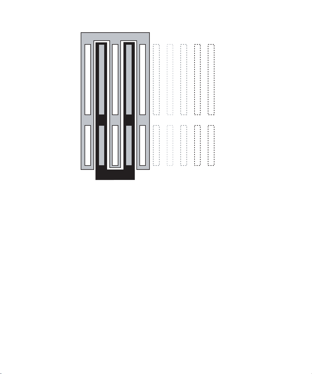
Domain A
•
•
•
System board 0
System board 1
System board 2
System board 3
System board 4
•
•
I/O 0
I/O 1
I/O 2
I/O 3
I/O 4
•
Domain B
FIGURE 2-2 Domains A and B after reconfiguration
System board 16
System board 17
I/O 16
I/O 17
Chapter 2 DR Concepts 25
Page 40

26 Sun Fire High-End and Midrange Systems Dynamic Reconfiguration User’s Guide • August 2005
Page 41
CHAPTER
3
Preparing to Use DR
This chapter, along with chapters 1 and 2, provides information and some
procedures you should understand to use DR successfully.
Caution – An improperly executed DR operation can cause DR to fail and, in some
cases, damage system components.
This chapter covers the following topics:
■ “The cfgadm(1M) Command” on page 27
■ “The rcfgadm(1M) Command (High-End Only)” on page 29
■ “Checking Device Type, State and Condition” on page 30
■ “Preparing to Use DR on a Domain” on page 30
■ “Displaying System Board Status” on page 31
■ “Testing Boards” on page 32
The cfgadm(1M) Command
The cfgadm(1M) command performs DR operations on the domain. DR operations
are passed to the libcfgadm(3LIB) library interface, which dynamically loads a
hardware-specific library plug-in that actually performs the DR operations.
Note – If the cfgadm(1M) command fails during a DR operation, the board does not
return to its original state. If the error is recoverable, you can retry the command. If
the error is unrecoverable, you must reboot the domain to use the board.
27
Page 42

The sbd.so.1 hardware-specific plug-in provides DR functionality: connect,
configure, unconfigure, and disconnect system boards, which enables you to connect
or disconnect a system board from a running system without having to reboot the
system.
The cfgadm(1M) command resides in the /usr/sbin directory. (See the
cfgadm(1M) man page for more information.)
Each board slot appears as a single attachment point in the device tree. You can view
the type, state, and condition of each component, and the state and condition of each
board slot, by using the cfgadm(1M) command with its -a option.
The following options and operands are supported for the functions shown, where
ap_id specifies the attachment point of the system board or component:
TABLE 3-1 cfgadm Options
Options and Operands Specifies
-c connect ap_id Change the receptacle state to connected.
-c disconnect ap_id Change the receptacle state to disconnected.
-c configure ap_id Change the occupant state to configured.
-c unconfigure ap_id Change the occupant state to unconfigured.
-x assign ap_id Change the occupant state to assigned.
-x unassign ap_id Change the occupant state to unassigned.
-x poweron ap_id Change the occupant state to powered on.
-x poweroff ap_id Change the occupant state to powered off.
-l ap_id Display the state, status, and condition of system
boards and components.
-h [ap_id] Print out a help message text. If ap_id is specified, the
help routine of the hardware-specific library for the
attachment point indicated by the argument is called.
-v Execute in verbose mode.
-n Automatically answer No to all prompts without
displaying them.
-y Automatically answer Yes to all prompts without
displaying them..
28 Sun Fire High-End and Midrange Systems Dynamic Reconfiguration User’s Guide • August 2005
Page 43

TABLE 3-1 cfgadm Options (Continued)
Options and Operands Specifies
-s listing_options The state of attachment points to be displayed
according to listing_options. Supplies listing options to
-l) flag. The listing_options argument conforms to the
syntax conventions of the getsubopt(3C) man page,
and specifies:
• Attachment point selection criteria (i.e., select=
select_string)
• Type of matching desired (i.e., match=
match_type)
• Order of listing (i.e., sort=field_spec)
• Data displayed (i.e., cols=field_spec and
cols2=field_spec)
• Column delimiter (i.e., delim=string)
• Column-heading suppression (i.e., noheadings).
-o hardware_options Supply hardware-specific options to the main
command option. The format and content of the
hardware_options string is completely hardwarespecific; and the string conforms to the syntax
conventions of the getsubopt(3C) man page.
-t ap_id Perform a test of one or more attachment points. The
test function is used to re-evaluate the condition of the
attachment point. Without a test-level specifier in
hardware_options, the fastest test that identifies hard
faults is used.
The rcfgadm(1M) Command (High-End Only)
The SMS command rcfgadm(1M) is executed on the SC and takes the same options
and operands as cfgadm(1M), but often requires addition of the -d domain_id
option. See
“rcfgadm(1M)” on page 67.
Chapter 3 Preparing to Use DR 29
Page 44

Checking Device Type, State and Condition
Before you attempt to perform any DR operation on a board or component from the
domain, determine its state and condition.
▼ To display states, types and conditions
● Use the cfgadm(1M) command with the -la options.
# cfgadm -la
▼ To display information about board slots and
components
● Use the prtdiag(1M) command.
# prtdiag
The prtdiag(1M) command displays board numbers.
Preparing to Use DR on a Domain
Before you perform DR operations for the first time on a domain after it has been
booted, make sure the board is available to the domain.
30 Sun Fire High-End and Midrange Systems Dynamic Reconfiguration User’s Guide • August 2005
Page 45

▼ To Display Boards Available to the Domain
● Use the cfgadm(1M) command with its -l option.
# cfgadm -l
On high-end systems each domain maintains an available component list. On
midrange systems, domains maintain access control lists. Both are referred to as
ACLs.
An error might occur if you attempt to perform DR operations on a board that is one
of the following:
■ Not listed in the domain’s ACL and not assigned to the domain.
■ Listed in the domain’s ACL, but assigned to another domain.
In either of these cases, the board is not available to the domain. For more
information about viewing the available component list on high-end systems, see the
System Management Services (SMS) Administrator Guide. For more info about ACLs on
midrange systems, see the Sun Fire Midrange Systems Platform Administrator Manual.
Displaying System Board Status
▼ To Display System Board Status
● Use the cfgadm(1M) command.
# cfgadm -a -s “select=class(sbd)”
The cfgadm(1M) command displays information about boards that are either
assigned to the domain, or appear in the ACL and are not assigned to another
domain. The -a option tells the command to list all known attachment points,
including board slots, SCSI buses, and PCI slots.
Chapter 3 Preparing to Use DR 31
Page 46

The following display shows a typical output on a midrange system domain.
TABLE 3-2 System Board Status Sample Display
Ap_Id Type Receptacle Occupant Condition
N0.IB6 PCI_I/O_Boa connected configured ok
N0.IB7 PCI_I/O_Boa connected configured ok
N0.IB8 PCI_I/O_Boa connected configured ok
N0.IB9 PCI_I/O_Boa disconnected unconfigured unknown
N0.SB0 CPU_Board connected configured unknown
N0.SB1 CPU_Board disconnected unconfigured failed
N0.SB2 CPU_Board connected configured ok
N0.SB3 unknown empty unconfigured unknown
N0.SB4 unknown empty unconfigured unknown
N0.SB5 unknown empty unconfigured unknown
To display more detailed information, add the -v option to cfgadm(1M).
Testing Boards
▼ To Test a System Board
● Use the cfgadm(1M) command with its -t option.
# cfgadm -t ap_id
where ap_id is an attachment point identifier.
● Use the cfgadm(1M) command with its -t and -o options to test at a specified
diagnostic level (midrange systems only).
# cfgadm -o platform=diag=<level> -t ap_id
where level is a diagnostic level and ap_id is an attachment point identifier.
32 Sun Fire High-End and Midrange Systems Dynamic Reconfiguration User’s Guide • August 2005
Page 47

If you do not specify the level on midrange systems, the setupdomain command
sets the default diagnostic level, as described in both the Sun Fire Midrange Systems
Platform Administration Manual and the Sun Fire Midrange System Controller Command
Reference Manual. The diagnostic levels are:
TABLE 3-3 Diagnostic Levels
Diagnostic Level Description
init Run, but do not test, system board initialization code, for a quick pass
through POST.
quick Test all system board components, but with few tests and test patterns.
default or max Test all system board components, except memory and Ecache modules,
with all tests and test patterns.
mem1 Run all tests at the default level, plus more exhaustive DRAM and
SRAM test algorithms. For Memory and Ecache modules, test all
locations with multiple patterns. More extensive, time-consuming
algorithms are not run at this level.
mem2 Run all tests in mem1, plus a DRAM test that does explicit compare
operations of the DRAM data.
▼ To Test an I/O Board (Midrange Only)
Note – You cannot use the DR connect and configure operations to add an I/O
board to a domain in a single-partition midrange system that is configured with one
or more UltraSPARC IV+ system boards. This restriction is due to the absence of a
second domain in which the I/O board can be tested. However, you can use the DR
unconfigure and disconnect commands on an I/O board in the described system.
For more information see the Sun Fire Midrange Systems Platform Administration
Manual, Firmware Release 5.19.0.
In this procedure, domain A is the current, active domain and domain B is the spare
domain.
1. Enter the domain shell of the spare domain (B).
2. Press and hold the CTRL key while pressing the ] key to bring up the telnet>
prompt.
3. At the telnet> prompt, type send break to display the system controller
domain shell.
Chapter 3 Preparing to Use DR 33
Page 48
4. In the spare domain (B) shell, add the I/O assembly to the domain.
schostname:B> addboard IBx
where x is 6, 7, 8, or 9.
5. Set the virtual keyswitch in the spare domain to on.
schostname:B> setkeyswitch on
.
.
{x} ok
where x represents the CPU. POST is run on the domain when you turn the virtual
keyswitch to on. If you see the
ok prompt, the I/O board or I/O assembly is
functioning properly.
6. Set the mode to standby.
schostname:B> setkeyswitch standby
7. Delete the board.
schostname:B> deleteboard ibx
8. Add the board to the active domain (A).
# cfgadm -c configure N0.IBx
▼ To Prepare an I/O Board for DR (High-End
Only)
Before you attempt to perform DR operations on an I/O board in a high-end system
domain, verify all the following are true:
■ At least two CPUs are available to the domain.
■ At least one of the two CPUs is located on a system board.
■ No processes are bound to that CPU.
See the pbind(1M) man page for more information about bound processes.
34 Sun Fire High-End and Midrange Systems Dynamic Reconfiguration User’s Guide • August 2005
Page 49

When you use DR to configure an I/O board into a domain (or to test an I/O board
explicitly using the cfgadm(1M) command with its -t option), one CPU that is an
occupant on a system board in the same domain is selected to test the board. Further,
no process can be bound to the CPU, and at least one additional CPU must remain in
the domain. If no such CPU is available to perform the test, a message such as the
following is displayed:
WARNING: No CPU available for I/O cage test
The CPU is unconfigured from the domain and the I/O board tested. After the test is
complete, the CPU is configured back into the domain. After the CPU is successfully
reconfigured, its timestamp as displayed by the psrinfo(1M) command differs
from timestamps for other CPUs in the domain.
Chapter 3 Preparing to Use DR 35
Page 50

36 Sun Fire High-End and Midrange Systems Dynamic Reconfiguration User’s Guide • August 2005
Page 51

CHAPTER
4
DR Procedures – From the System
Domain
This chapter contains procedures that describe how to use the DR feature from the
Sun Fire system domain on high-end and midrange systems. Procedures that apply
to one platform but not the other are clearly marked. The terms system board and I/O
board apply to both platforms.
Caution – Before you attempt to perform any DR operation on a board or
component, determine its state and condition as described in “Checking Device
Type, State and Condition” on page 30.
Do not execute any of the procedures in this section until you understand the
information in chapters 1, 2 and 3.
You must be superuser to run DR in a domain.
Note – Wherever you see SBx or IOx, the x represents the board id number.
This chapter covers the following topics:
■ “Adding System Boards” on page 38
■ “Deleting System Boards” on page 40
■ “Moving System Boards” on page 42
■ “Adding I/O Boards” on page 43
■ “Adding/Deleting/Tracking Memory and CPU” on page 45
■ “PCI Adapter Card Operations” on page 47
37
Page 52

Adding System Boards
To add a system board to the domain, the board must already be assigned to the
domain, or must be in the ACL, an abbreviation for available component list on a
high-end system domain and access control list on midrange system domains.
For information about the high-end system ACL, see the System Management Services
(SMS) Administrator Guide. For information about the midrange system ACL, see the
Sun Fire Midrange Systems Platform Administration Manual.
▼ To Add a System Board
1. Verify that the selected board slot can accept a board.
# cfgadm -a -s “select=class(sbd)”
The states and conditions should be:
■ Receptacle state—Empty
■ Occupant state—Unconfigured
■ Condition—Unknown
-OR-
■ Receptacle state—Disconnected
■ Occupant state—Unconfigured
■ Condition—Unknown
2. Add the board to the slot, then connect and configure the board.
# cfgadm -v -c configure SBx
After a short delay during which the system tests the board, a message displays in
the domain console log indicating that the components have been configured. The
states and conditions for a connected and configured attachment point should be:
■ Receptacle state—Connected
■ Occupant state—Configured
■ Condition—OK
Now the system is aware of the usable devices on the board and the devices can be
used.
38 Sun Fire High-End and Midrange Systems Dynamic Reconfiguration User’s Guide • August 2005
Page 53

Note – If the cfgadm(1M) command fails during a DR operation, the board does not
return to its original state. If the error is recoverable, you can retry the command. If
the error is unrecoverable, you must reboot the domain to use the board.
▼ To Connect a System Board But Not Configure it
1. Verify that the selected board slot can accept a board.
# cfgadm -a -s “select=class(sbd)”
The states and conditions should be:
■ Receptacle state—Empty
■ Occupant state—Unconfigured
■ Condition—Unknown
-OR-
■ Receptacle state—Disconnected
■ Occupant state—Unconfigured
■ Condition—Unknown
2. Connect the board.
# cfgadm -v -c connect SBx
▼ To Configure a Connected System Board
● Configure the connected board.
# cfgadm -c configure SBx
where x represents the number of the board.
Chapter 4 DR Procedures – From the System Domain 39
Page 54

Deleting System Boards
▼ To Delete a System Board
● Unconfigure and disconnect the board.
# cfgadm -c disconnect SBx
▼ To Unconfigure But Not Disconnect a System
Board
● Unconfigure the board.
# cfgadm -c unconfigure SBx
▼ To Delete an Unconfigured System Board
● Disconnect the board.
# cfgadm -c disconnect SBx
▼ To Delete a System Board Temporarily
Use this procedure to power off the board and leave it in place if, for example, a
board fails and no replacement board or system board filler panel is available.
1. Identify the attachment point ID for the board.
# cfgadm -l -s "select=class(sbd)"
40 Sun Fire High-End and Midrange Systems Dynamic Reconfiguration User’s Guide • August 2005
Page 55

2. Detach and power off the board.
# cfgadm -c disconnect ap_id
where ap_id is the attachment point ID returned by the command in Step 1.
▼ To Find the System Board that Contains a
Domain’s Permanent Memory
● Identify the board that contains permanent memory.
# cfgadm -val | grep permanent
▼ To Unconfigure a System Board with Permanent
Memory
1. Identify the board that contains permanent memory.
# cfgadm -val | grep permanent
2. Unconfigure the board that contains permanent memory.
# cfgadm -c unconfigure -y SB0
Note – Using the -y option here does not prevent the quiesce.
Chapter 4 DR Procedures – From the System Domain 41
Page 56

Moving System Boards
▼ To Move a System Board Between Domains
1. Identify the slot number of the board to be removed.
# cfgadm -l -s "select=class(sbd)"
2. Unconfigure the board but leave the power on to preserve the test status:
# cfgadm -o unassign,nopoweroff -c disconnect ap_id
where ap_id is the attachment point ID returned by Step 1.
At this point, the slot is not assigned to any domain, and the slot is visible to all
domains.
3. In the domain to which you are moving the board, check to see if the board is now
visible as disconnected.
# cfgadm -al -s “select=class(sbd)”
Note – If the board is not visible in the new domain, the problem might be related
to the ACL, as this procedure implies an assignment operation. For information
about the available component list on a high-end system domain, see the System
Management Services (SMS) Administrator Guide. For information about the ACL on a
midrange system domain, see the Sun Fire Midrange Systems Platform Administration
Manual.
4. Configure the board in the new domain.
# cfgadm -c configure ap_id
42 Sun Fire High-End and Midrange Systems Dynamic Reconfiguration User’s Guide • August 2005
Page 57

Adding I/O Boards
▼ To Add an I/O Board
1. Verify that the selected board slot can accept a board.
# cfgadm -a -s “select=class(sbd)”
The states and conditions should be:
■ Receptacle state—Empty
■ Occupant state—Unconfigured
■ Condition—Unknown
-OR-
■ Receptacle state—Disconnected
■ Occupant state—Unconfigured
■ Condition—Unknown
2. Add the board to the slot.
3. For a midrange system, test the I/O board; for a high-end system, proceed to the
next step.
If you are adding a board to a midrange system, see “To Test an I/O Board
(Midrange Only)” on page 33.
4. Connect and configure the board.
# cfgadm -v -c configure IOx
After a short delay during which the system tests the board, a message displays in
the domain console log indicating that the components have been configured. The
states and conditions for a connected and configured attachment point should be:
■ Receptacle state—Connected
■ Occupant state—Configured
■ Condition—OK
Now the system is aware of the usable devices on the board and the devices can be
used.
Chapter 4 DR Procedures – From the System Domain 43
Page 58
Note – If the cfgadm(1M) command fails during a DR operation, the board does not
return to its original state. If the error is recoverable, you can retry the command. If
the error is unrecoverable, you must reboot the domain to use the board.
▼ To Add and Connect an I/O Board But Not
Configure it
1. Verify that the selected board slot can accept a board.
# cfgadm -a -s “select=class(sbd)”
The states and conditions should be:
■ Receptacle state—Empty
■ Occupant state—Unconfigured
■ Condition—Unknown
-OR-
■ Receptacle state—Disconnected
■ Occupant state—Unconfigured
■ Condition—Unknown
2. Add the board to the slot.
3. For a midrange system, test the I/O board; for a high-end system, proceed to the
next step.
If you are adding a board to a midrange system, see “To Test an I/O Board
(Midrange Only)” on page 33.
4. Connect the board.
# cfgadm -v -c connect IOx
▼ To Configure a Connected I/O Board
● Configure the connected I/O board.
# cfgadm -c configure IOx
44 Sun Fire High-End and Midrange Systems Dynamic Reconfiguration User’s Guide • August 2005
Page 59
▼ To Delete an I/O Board
● Unconfigure and disconnect the I/O board.
# cfgadm -c disconnect IOx
▼ To Unconfigure an I/O Board But Not
Disconnect it
● Unconfigure the I/O board without disconnecting it.
# cfgadm -c unconfigure IOx
▼ To Disconnect an Unconfigured I/O Board
● Disconnect the unconfigured I/O board.
# cfgadm -c disconnect IOx
Adding/Deleting/Tracking Memory and CPU
Note – The following procedures apply to both single-core and dual-core CPUs.
▼ To Configure CPU on a System Board
● Configure the CPU.
# cfgadm -c configure SBx::cpuy
Chapter 4 DR Procedures – From the System Domain 45
Page 60

where x represents the board number and y represents the CPU number, which is 0
through 3 for Sun Fire high-end and midrange systems.
▼ To Configure Memory on a System Board
● Configure memory.
# cfgadm -c configure SBx::memory
where x represents the board number. For memory, the command applies to all
the memory on the system board
▼ To Configure All CPUs and Memory on a
System Board
● Configure all CPUs and memory on the board.
# cfgadm -c configure SBx
▼ To Unconfigure CPU on a System Board
● Unonfigure the CPU.
# cfgadm -c unconfigure SBx::cpuy
where x represents the board number and y represents the CPU number, which is 0
through 3 for Sun Fire high-end and midrange systems.
▼ To Unconfigure Memory on a System Board
● Configure memory.
# cfgadm -c unconfigure SBx::memory
46 Sun Fire High-End and Midrange Systems Dynamic Reconfiguration User’s Guide • August 2005
Page 61

where x represents the board number. For memory, the command applies to all
the memory on the system board
▼ To Unconfigure All CPUs and Memory on a
System Board
● Unconfigure all CPUs and memory on the board.
# cfgadm -c unconfigure SBx
▼ To Track a Memory Unconfigure Operation
You can use the cfgadm(1M) command to track the progress of a memory
unconfigure operation. The following command displays a snapshot of the amount
of memory deleted, and the amount of memory remaining to delete.
● Track the memory-delete process.
# cfgadm -a -s “select=type(memory),cols=ap_id:o_state:info”
PCI Adapter Card Operations
Each hot-plug slot on an I/O board can be individually connected, configured,
unconfigured, and disconnected. Each attachment point for a hot-plug slot, which
identifies both the slot and the adapter card that is plugged into the slot, is created
when the I/O board is configured into the domain.
Sun Fire high-end systems support PCI and hsPCI cards. Sun Fire midrange systems
support PCI and CompactPCI cards. In the procedures that follow, PCI refers to any
of these card types.
Chapter 4 DR Procedures – From the System Domain 47
Page 62
▼ To Connect a PCI slot on an I/O Board
● Connect the PCI slot.
# cfgadm -c connect pci_ap_id
where pci_ap_id represents the ID of the PCI slot.
For example, to connect, but not configure, an adapter at slot 1 of I/O board 1 into a
domain, use a command such as the following:
# cfgadm -c connect pcisch0:e01b1slot1
▼ To Configure a PCI slot on an I/O Board
● Configure the PCI slot.
# cfgadm -c configure pci_ap_id
where pci_ap_id represents the ID of the PCI slot.
For example, to configure the adapter at slot 1 of I/O board 1 into the domain, use a
command such as the following:
# cfgadm -c configure pcisch0:e01b1slot1
▼ To Disconnect a PCI slot on an I/O Board
● Disconnect the PCI slot.
# cfgadm -c disconnect pci_ap_id
where pci_ap_id represents the ID of the PCI slot.
48 Sun Fire High-End and Midrange Systems Dynamic Reconfiguration User’s Guide • August 2005
Page 63
For example, to disconnect an adapter at slot 1 of I/O board 1 before unplugging the
adapter, use a command such as the following:
# cfgadm -c disconnect pcisch13:eo1b1slot1
▼ To Unconfigure a PCI Slot on an I/O Board
● Unconfigure the PCI slot.
# cfgadm -c unconfigure pci_ap_id
where pci_ap_id represents the ID of the PCI slot.
For example, to unconfigure the adapter at slot 1 of I/O board 1 out of the domain,
use a command such as the following:
# cfgadm -c unconfigure pcisch0:e01b1slot1
For more information, see cfgadm_pci(1M).
Chapter 4 DR Procedures – From the System Domain 49
Page 64

50 Sun Fire High-End and Midrange Systems Dynamic Reconfiguration User’s Guide • August 2005
Page 65

CHAPTER
5
SMS DR Procedures – From the SC
(High-End Only)
This chapter describes procedures for using DR from the Sun Fire high-end server
system controller (SC), which runs the system management services (SMS) software.
Caution – Before you attempt to perform any DR operation on a board or
component, determine its state and condition, as described in “Preparing to Use DR”
on page 27.
This chapter covers the following topics:
■ “Showing Device Information” on page 52
■ “Showing Platform Information” on page 54
■ “Showing Board Information” on page 55
■ “Adding Boards” on page 57
■ “Deleting Boards” on page 58
■ “Moving Boards” on page 59
■ “Replacing Active System Boards” on page 60
■ “SMS DR Commands and Options” on page 61
■ “Error Message Help System” on page 70
Note – If an SMS DR command fails during a DR operation, the board does not
return to its original state. If the error is recoverable, you can retry the command. If
the error is unrecoverable, you must reboot the domain to use the board.
The SMS DR command rcfgadm(1M) works very much like cfgadm(1M) in the
domain, accepting the same options. The main visible difference is that
rcfgadm(1M) often requires an additional -d domain_id parameter. This chapter
focuses on other SMS commands. For information about rcfgadm(1M), see
“rcfgadm(1M)” on page 67.
51
Page 66

Showing Device Information
Before you attempt to perform any DR operation, use the SMS command
showdevices(1M) to display device information, especially before removing
devices.
▼ To Show Device Information
● Display device information for the domain.
# showdevices -v -d domain_id
showdevices(1M) displays information about all devices in the domain and
produces output similar to that in the following tables
TABLE 5-1 showdevices Sample Output, CPU
domain board id state speed ecache usage
A SB1 40 online 400 4
A SB1 41 online 400 4
A SB1 42 online 400 4
A SB1 43 online 400 4
A SB2 55 online 400 4
A SB2 56 online 400 4
A SB2 57 online 400 4
A SB2 58 online 400 4
.
TABLE 5-2 showdevices Sample Output, UltraSPARC IV+ (showdevices -d G)
domain board id state speed ecache usage
G SB0 0 on-line 1050 8
G SB0 1 on-line 1050 8
G SB0 2 on-line 1050 8
G SB0 3 on-line 1050 8
52 Sun Fire High-End and Midrange Systems Dynamic Reconfiguration User’s Guide • August 2005
Page 67

TABLE 5-2 showdevices Sample Output, UltraSPARC IV+ (showdevices -d G)
domain board id state speed ecache usage
G SB0 4 on-line 1050 8
G SB0 5 on-line 1050 8
G SB0 6 on-line 1050 8
G SB0 7 on-line 1050 8
G SB9 288 on-line 900 8
G SB9 289 on-line 900 8
G SB9 290 on-line 900 8
G SB9 291 on-line 900 8
G SB12 384 on-line 900 8
G SB12 385 on-line 900 8
G SB12 386 on-line 900 8
G SB12 387 on-line 900 8
TABLE 5-3 showdevices Sample Output, Memory Drain In-Progress
domain board board
mem MB
A SB1 2048 933 0x600000 4096
perm
mem MB
base addr domain
mem MB
target
deleted MBremaining
board
C2 250 1500
A SB2 2048 0 0x200000 4096
TABLE 5-4 showdevices Sample Output, IO Devices
domain board device resource usage
A 101 sd0
A 101 sd1
A 101 sd2
A 101 sd3 /dev/dsk/c0t3d0s0 mounted from
filesystem “/”
A 101 sd3 /dev/dsk/c0t3d0s1 dump device (swap)
A 101 sd3 /dev/dsk/c0t3d0s1 swap area
A 101 sd3 /dev/dsk/c0t3d0s3 mounted filesystem
“/var”
Chapter 5 SMS DR Procedures – From the SC (High-End Only) 53
MB
Page 68

TABLE 5-4 showdevices Sample Output, IO Devices (Continued)
A 101 sd3 /var/run mounted filesystem
“/var/run”
A 101 sd4
A 101 sd5
For more information see “showdevices(1M)” on page 69, or see the
showdevices(1M) man page for a complete list of options and arguments, and for
information about displaying device-specific information.
Showing Platform Information
Before you attempt to add, move, or delete a board to or from a specific domain, use
the showboards(1M) command to determine the domain ID, the boards available to
the domain, and the status of the domain.
You can use the domain ID with all DR commands. You can use the board list to
determine the domain to which a specific board is assigned, and you can use the
domain status to determine whether or not you can add, delete, or move a board to
or from the domain. Use the showplatform(1M) command to determine whether
the component is in the available component list (ACL).
You must have the appropriate privileges to use the showplatform(1M) command.
See
“showplatform(1M)” on page 70 for more information, including a table that
shows which user groups can use it.
54 Sun Fire High-End and Midrange Systems Dynamic Reconfiguration User’s Guide • August 2005
Page 69
▼ To Show Platform Information
● List domain and ACL information.
# showplatform
The showplatform(1M) command displays the domain ID, the ACL, and the status
of the domain, as in the following example.
ACLs for domain domainA:
slot0: SB0, SB1, SB2, SB3
slot1: IO0, IO1, IO2, IO3
ACLs for domain domainB:
slot0: None
slot1: None
Domain Solaris Nodename Domain Status
domainA sms3-b0 Powered Off
domainB sms3-b1 Running Solaris
Showing Board Information
Before you attempt to delete or move a system board, you must query the board to
determine the state of the board and the domain to which it is assigned. See
“showboards(1M)” on page 68 for more information. including a table showing
which user groups can use it, and the showboards(1M) man page.
SC State Models
On the Sun Fire high-end server SC, a board can be in one of four states: unavailable,
available, assigned, or active.
Chapter 5 SMS DR Procedures – From the SC (High-End Only) 55
Page 70

Note – The state of a board on the SC is not the same as the state of a board on the
domain. For more information about board states on the domain, see
“DR Concepts”
on page 7.
TABLE 5-5 Board State Conditions on the Sun Fire High-End Systems SC
Name Description
unavailable The board is unavailable to the domain. The board has not been
added to the ACL for the specified domain, or the board is currently
assigned to another domain. Note that boards that are not in the
ACL are invisible to the domain. In the unavailable state, the
board is not considered part of the specified domain.
available The board is available to be added to the domain. The board is in
the ACL for the domain. Note that the board can be available to any
number of domains. In the available state, the board is not
considered to be part of the logical domain.
assigned The board has been assigned to the domain, and might be in the
domain’s ACL. The board is unavailable to any other domain. In the
assigned state, the board is considered to be part of the logical
domain.
active The board has been connected. Or, the board has been connected
and configured into the Solaris OS and is available for use by the
operating system. In the active state, the board is considered part
of the physical domain.
The showboards(1M) command
After you have determined the domain ID that contains the board that you want to
delete or move, or after you have determined that a particular board has already
been assigned to a specific domain, use the showboards(1M) command to
determine the state of the board. The board might be in a state that makes it
impossible for you to delete or move it.
Note – The output of the showboards(1M) command depends on the privileges of
the user. For instance, the platform administrator can obtain information about all of
the boards in the server. The domain administrator and domain configurator,
however, can obtain the information about only those boards that are assigned and
available to the domain(s) to which they have access. For more information, see
“showboards(1M)” on page 68 and the showboards(1M) man page.
56 Sun Fire High-End and Midrange Systems Dynamic Reconfiguration User’s Guide • August 2005
Page 71

▼ To Show Board Information
● Display board information for the domain.
# showboards -d domain_id
The above command displays the device information similar to the following:
Slot Power Board Type Board Status Test Status Domain
SB0 On CPU Board Active Passed A
SB1 - Empty Slot Assigned - A
You can use the showboards(1M) command to display all assigned and available
system boards, and all I/O boards in the domain. See the showboards(1M) man
page for more information about showing board information.
Adding Boards
Adding a board to a domain moves the board through several state changes. If it is
not already assigned, it is first assigned to the domain. Then, it is connected to the
domain and configured into the Solaris OS. After it is connected, it is considered part
of the physical domain and available for use by the operating system.
You must have the appropriate privileges to add a board to a domain. For more
information, including a description of the privileges needed to use this command,
see
“addboard(1M)” on page 61 and the addboard(1M) man page.
Note – Before you use DR to add a COD board into a domain, make sure the system
has enough RTU licenses available to the target domain to enable each active CPU
on the COD board. Otherwise, DR displays a message for each CPU that cannot be
enabled in the domain. For more information about the COD option, see the System
Management Services (SMS) Administrator Guide.
Chapter 5 SMS DR Procedures – From the SC (High-End Only) 57
Page 72
▼ To Add a Board to a Domain
● Add the board to the domain.
# addboard -d domain_id board_id
The following example adds system board 2 (SB2) to domain A. Two retries are
performed, if necessary, with a wait time of 10 minutes (600 seconds) between
retries.
# addboard -d A -r 2 -t 600 SB2
Note – If the addboard(1M) command fails during a DR operation, the board does
not return to its original state. A dxs or dca error message is logged to the domain.
If the error is recoverable, you can retry the command. If the error is unrecoverable,
you must reboot the domain to use the board.
Deleting Boards
Deleting a board from a domain removes the board from the domain to which it is
currently assigned, and in which it might be active. To delete a board, it must be in
the assigned or active state.
Always check the usage of the components on a board before you delete it from a
domain. If the board hosts permanent memory, the memory is moved to another
board within the same domain before the board is deleted from the domain.
Likewise, if any busy devices are present, you must wait or ensure that the device is
no longer being used by the system before you attempt to remove the board.
A domain administrator can unconfigure and disconnect a board, but cannot
unassign a board from a domain unless the board is in the ACL. For more
information, including a description of privileges required to use this command, see
“deleteboard(1M)” on page 63 and the deleteboard(1M) man page.
58 Sun Fire High-End and Midrange Systems Dynamic Reconfiguration User’s Guide • August 2005
Page 73

▼ To Delete a Board From a Domain
● Delete the board from the domain.
# deleteboard board_id
The following example of the deleteboard(1M) command deletes system board 2
(SB2) from its current domain. Two retries are performed, if necessary, with a wait
time of 15 minutes (900 seconds) between retries.
# deleteboard -r 2 -t 900 SB2
Note – If the deleteboard(1M) command fails during a DR operation, the board
does not return to its original state. A dxs or dca error message is logged to the
domain. If the error is recoverable, you can retry the command. If the error is
unrecoverable, you must reboot the domain to use the board.
Moving Boards
Moving a board from one domain to another domain is performed in several steps.
First, the board is removed from the domain to which it is currently assigned, and in
which it might be active; the board must be in the assigned or active state. Next, it is
assigned to the target domain. Then, it is connected to the target domain and
configured into the Solaris OS, where it becomes available for use.
You should always check the usage of the memory and devices on a board before
you move it out of a domain. If the board hosts permanent memory, the memory
must be moved to another board within the same domain before the board can be
moved to another domain. Likewise, if any busy devices are present, you must wait
or ensure that the device is no longer being used by the system before you attempt
to move the board.
For more information, including a description of privileges required to use this
command, see
“moveboard(1M)” on page 65 and the moveboard(1M) man page.
Chapter 5 SMS DR Procedures – From the SC (High-End Only) 59
Page 74

Note – Before you use DR to move a COD board into a domain, make sure the
ssytem has enough RTU licenses available to the target domain to enable each active
CPU on the COD board. Otherwise, DR displays a message for each CPU that cannot
be enabled in the domain. For more information about the COD option, see the
System Management Services (SMS) Administrator Guide.
▼ To Move a Board
● Move the board from one domain to another domain.
# moveboard -d domain_id board_id
The following example of the moveboard(1M) command moves system board 2
(SB2) from its current domain to domain A. Two retries are performed, if necessary,
with a wait time of 15 minutes (900 seconds) between retires.
# moveboard -d A -r 2 -t 900 SB2
Note – If the moveboard(1M) command fails during a DR operation, the board does
not return to its original state. A dxs or dca error message is logged to the domain.
If the error is recoverable, you can retry the command. If the error is unrecoverable,
you must reboot the domain to use the board.
Replacing Active System Boards
This section describes how to replace a system board that is active in a domain.
▼ To Replace an Active System Board
1. Delete the system board from its current domain.
# deleteboard board_id
60 Sun Fire High-End and Midrange Systems Dynamic Reconfiguration User’s Guide • August 2005
Page 75
The following example removes system board 2 (SB2) from its current domain:
# deleteboard -r 2 -t 900 SB2
2. Add the replacement board to the specified domain.
# addboard -d domain_id board_id
The following example adds system board 3 to the domain A. Two retries are
performed, if necessary, with a wait time of 15 minutes (900 seconds) between
retries.
# addboard -d A -r 2 -t 900 SB3
SMS DR Commands and Options
This section contains descriptions of the SMS DR commands and related options. For
more information about each SMS DR command, see the System Management Services
(SMS) Reference Manual.
addboard(1M)
The addboard(1M) command attaches board to a domain. See “Adding Boards” on
page 57 and the addboard(1M) man page for more information.
TABLE 5-6 addboard Command Options
Options and Operands Specifies
board_id The ID of the board to be added. The board ID
corresponds to the board location. For example, SB2 is
the board in slot 2. Multiple board identifiers are
permitted.
-c function Configure the board into the specified configuration
state. You can add a board by steps. For example, you
can assign the board, connect it, then configure it.
-d domain_id Execute the DR operation in the specified domain.
Chapter 5 SMS DR Procedures – From the SC (High-End Only) 61
Page 76

TABLE 5-6 addboard Command Options (Continued)
Options and Operands Specifies
-f Force the specified action to occur. Typically, this is a
hardware-specific override of a safety feature. Forcing a
state change operation can allow use of the hardware
resources of an occupant that is not in the ok or
unknown conditions, at the discretion of any hardwaredependent safety checks.
-h Display Help (usage) information.
-n Answer No to all prompts.
-q Run in quiet mode. Messages and prompts are not
written to standard output. When used alone, -q
defaults to the -n option for all prompts.
-r retry_count If the operation fails, retry the specified number of times.
-t timeout Wait the specified time, in seconds, between retries.
-y Answer Ye s to all prompts.
TABLE 5-7 describes the privileges needed to use the addboard(1M) command. The
platform operator, platform service, and superuser groups cannot initiate this
command.
TABLE 5-7 Privileges Needed to Use the addboard command
Platform Admin Domain Admin Domain Configurator
Can assign a board to a
domain using the -c
option with the assign
function.
Can connect or configure a
board into a domain if the
board has been assigned to the
domain, or if it appears in the
ACL for the domain and is not
assigned to another domain.
Can connect or configure a
board into a domain if the
board has been assigned to
the domain, or if it appears in
the ACL for the domain and
is not assigned to another
domain.
The following example attaches system board 2 (SB2) to domainA. Two retries are
performed, if necessary, with a wait time of 10 minutes (600 seconds) between
retries.
# addboard -d domainA -r 2 -t 600 SB2
62 Sun Fire High-End and Midrange Systems Dynamic Reconfiguration User’s Guide • August 2005
Page 77

Note – If addboard(1M) fails during a DR operation, the board does not return to
its original state. A dxs or dca error message is logged to the domain. If the error is
recoverable, you can retry the command. If the error is unrecoverable, you must
reboot the domain to use the board.
deleteboard(1M)
The deleteboard(1M) command detaches a board from a domain. See “Deleting
Boards” on page 58 and the deleteboard(1M) man page for more information.
TABLE 5-8 deleteboard Command Options
Options and Operands Specifies
board_id The ID of the board to be deleted. The board ID
corresponds to the board location. For example, SB2 is
the system board in slot 2. Multiple board identifiers are
permitted.
-c function Configure the board into the specified configuration
state. You can delete a board by steps. For example, you
can unconfigure the board, disconnect it, and then
unassign it.
-f Force the specified action to occur. Typically, this is a
hardware-specific override of a safety feature. Forcing a
state change operation can allow use of the hardware
resources of an occupant that is not in the ok or
unknown conditions, at the discretion of any hardwaredependent safety checks.
-h Display Help (usage) information.
-n Answer No to all prompts.
-q Run in quiet mode. Messages and prompts are not
written to standard output. When used alone, -q
defaults to the -n option for all prompts.
-r retry_count If the operation fails, retry the specified number of times.
-t timeout Wait the specified time, in seconds, between retries.
-y Answer Ye s to all prompts.
Chapter 5 SMS DR Procedures – From the SC (High-End Only) 63
Page 78

TABLE 5-9 describes the privileges needed to use the deleteboard(1M) command.
The platform operator, platform service, and superuser groups cannot initiate this
command.
TABLE 5-9 Privileges Needed to Use the deleteboard Command
Platform Admin Domain Admin Domain Configurator
Can unassign boards that
are not active in a
domain by using the -c
option with the
unassign function. If
the user also has domain
privileges,
deleteboard also
unconfigures and
disconnects the board
before it unassigns it.
Can unconfigure, disconnect or
unassign a board from the
domain. The board can be
unassigned from the domain
only if it appears in the ACL.
Can unconfigure, disconnect
or unassign a board from the
domain. The board can be
unassigned from the domain
only if it appears in the ACL.
The following example of the deleteboard(1M) command detaches system board 2
(SB2) from its current domain. The command specifies two retries at 15-minute (900second) intervals.
# deleteboard -r 2 -t 900 SB2
Note – If deleteboard(1M) fails during a DR operation, the board does not return
to its original state. A dxs or dca error message is logged to the domain. If the error
is recoverable, you can retry the command. If the error is unrecoverable, you must
reboot the domain to use the board.
64 Sun Fire High-End and Midrange Systems Dynamic Reconfiguration User’s Guide • August 2005
Page 79

moveboard(1M)
The moveboard(1M) command detaches a board from a domain, then attaches it to
another domain. See
page for more information.
TABLE 5-10 moveboard Command Options
Options and Operands Specifies
board_id The ID of the board to be moved. The board ID
-c function Configure the board into the specified configuration state.
-d domain_id Execute the DR operation on the specified domain.
-f Force the specified action to occur. Typically, this is a
-h Display Help (usage) information.
-n Answer No to all prompts.
-q Run in quiet mode. Messages and prompts are not written
-r retry_count If the operation fails, retry the specified number of times.
-t timeout Wait the specified time, in seconds, between retries.
-y Answer Yes to all prompts.
“Moving Boards” on page 59 and the moveboard(1M) man
corresponds to the board location. For example, SB2 is the
system board in slot 2. Multiple board identifiers are
permitted.
You can move a board by steps. For example, you can
assign the board, connect it, and then configure it.
hardware-specific override of a safety feature. Forcing a
state change operation can allow use of the hardware
resources of an occupant that is not in the ok or unknown
conditions, at the discretion of any hardware-dependent
safety checks.
to standard output. When used alone, -q defaults to the n option for all prompts.
Chapter 5 SMS DR Procedures – From the SC (High-End Only) 65
Page 80

TABLE 5-11 describes the privileges needed to use the moveboard(1M) command. The
platform operator, platform service, and superuser groups cannot initiate this
command.
TABLE 5-11 Privileges Needed to Use the moveboard Command
Platform Admin Domain Admin Domain Configurator
Can re-assign boards
from one domain to
another domain by using
the -c option with the
assign function. The
board cannot be active in
the domain from which
it is being re-assigned.
Can assign, connect, or
configure a board that is in
another domain. If the board is
active in another domain, the
moveboard command
unconfigures and disconnects
the board from that domain.
The board must be in the ACL
in order to unassign and reassign it using moveboard.
The moveboard command can
connect and configure the
board.
Can assign, connect, or
configure a board that is in
another domain. If the board
is active in another domain,
the moveboard command
unconfigures and disconnects
the board from that domain.
The board must be in the
ACL in order to unassign and
re-assign it using
moveboard. The moveboard
command can connect and
configure the board.
The domain administrator
must have domain privileges
for both domains to use the
moveboard(1M) command.
The domain configurator
must have domain privileges
for both domains to use the
moveboard(1M) command.
The following example of the moveboard(1M) command moves system board 5
(SB5) from its current domain to domain B. The command specifies two retries at 15minute (900-second) intervals.
# moveboard -d domainB -r 2 -t 900 SB5
Note – If the moveboard(1M) command fails during a DR operation, the board does
not return to its original state. A dxs or dca error message is logged to the domain.
If the error is recoverable, you can retry the command. If the error is unrecoverable,
you must reboot the domain to use the board.
66 Sun Fire High-End and Midrange Systems Dynamic Reconfiguration User’s Guide • August 2005
Page 81

rcfgadm(1M)
The rcfgadm(1M) command performs DR operations from the SC, providing remote
configuration administration operations on attachment points, which are device
nodes in the device tree. See the rcfgadm(1M) man page for more information and
examples of how to use this command.
TABLE 5-12 describes the rcfgadm(1M) command options and operands.
TABLE 5-12 rcfgadm Command Options
Options and Operands Specifies
-a List dynamic attachment points.
-c function Configure the board into the specified configuration
state: connect, disconnect, configure, or
unconfigure.
-d domain_id Execute the DR operation on the specified domain.
-f Force the specified action.
-h
-h ap_id
-h ap_type
-l ap_id | ap_type List the state and condition of the specified attachment
-n Answer No to all prompts.
-o hardware_options Use the specified hardware-specific options.
-r retry_count If the operation fails, retry the specified number of times.
-s listing_options List the specified listing options.
-T timeout Wait the specified time, in seconds, between retries.
-t Test one or more attachment points.
-v Execute in verbose mode.
-x hardware_function Use hardware-specific functions.
-y Answer Yes to all prompts.
Print the specified help message. If ap_id or ap_type is
given, display the hardware-specific help for the
attachment point.
points.
Chapter 5 SMS DR Procedures – From the SC (High-End Only) 67
Page 82

TABLE 5-13 describes the privileges needed to use the rcfgadm(1M) command. The
platform operator, platform service, and superuser groups cannot initiate this
command.
TABLE 5-13 Privileges Needed to Use the rcfgadm Command
Platform Admin Domain Admin Domain Configurator
Can assign boards to, or
unassign boards them from,
a domain by using the -x
option with the assign or
unassign function,
respectively. To use the
unassign function, the
board must be assigned and
cannot be active in a running
domain.
Can disconnect, connect,
configure, or unconfigure a
board to or from the domain.
Can assign or unassign a
board if the board is in the
domain’s ACL.
Can disconnect, connect,
configure, or unconfigure a
board to or from the domain.
Can assign or unassign a
board if the board is in the
domain’s ACL.
Note – If rcfgadm(1M) fails during a DR operation, the board does not return to its
original state. A dxs or dca error message is logged to the domain. If the error is
recoverable, you can retry the command. If the error is unrecoverable, you must
reboot the domain to use the board.
scdrhelp(1M)
The scdrhelp(1M) shell script starts the Sun Fire high-end server dynamic
reconfiguration error help system. The help system uses the JavaHelp™ hsviewer
script.
All user privilege groups can use this command except domain administrator and
domain configurator.
See “Error Message Help System” on page 70 and the scdrhelp(1M) man page for
more information about this script.
showboards(1M)
The showboards(1M) command displays assignment information and status of
system boards in a domain, and indicates whether a board is a Capacity On Demand
(COD) board. See
showboards(1M) man page for more information.
68 Sun Fire High-End and Midrange Systems Dynamic Reconfiguration User’s Guide • August 2005
“Showing Board Information” on page 55 and the
Page 83

Although showboards(1M) is not a DR-specific command, Sun suggests you use it
with DR commands.
TABLE 5-14 showboards Command Options
Option Specifies
-d domain_id Execute the DR operation on the specified domain.
-h Display Help (usage) information.
-v Execute in verbose mode. In this mode the command
TABLE 5-14 describes the showboards(1M) command options.
displays all components, including domain configurable
units (DCUs), which include CPUs, PCIs, and SCs.
All user privilege groups can use this command, but domain administrators and
domain configurators can show boards only in the domains for which they have
privileges.
showdevices(1M)
The showdevices(1M) command displays the configured physical devices on
system boards and the resources made available by these devices. Although the
showdevices(1M) command is not DR-specific, Sun sugggests you use it with DR
commands. See
showdevices(1M) man page for more information.
“Showing Device Information” on page 52 and the
Usage information is provided by applications and subsystems that are actively
managing system resources. To see the predicted impact of a system board DR
operation, do an offline query of managed resources.
TABLE 5-15 showdevices Command Options
Options and Operands Specifies
board_id The ID of the board to be added. The board ID
corresponds to the board location. For example, SB2 is
the system board in slot 2. Multiple board identifiers are
permitted.
-d domain_id Execute the DR operation in the specified domain.
-h Display Help (usage) information.
-p reports Show offline query information.
-v Display information about all I/O devices.
Chapter 5 SMS DR Procedures – From the SC (High-End Only) 69
Page 84

Only the domain administrator and the domain configurator can display device
information about a domain. And they can do so only for domains for which they
have privileges.
showplatform(1M)
The showplatform(1M) command shows the ACL, domain state for each domain,
and Capacity on Demand (COD) information. Although the showplatform(1M)
command is not DR-specific, Sun suggests you use it with DR commands. See
“Showing Platform Information” on page 54 and the showplatform(1M) man page
for more information.
TABLE 5-16 showplatform Command Options
Options and Operands Specifies
-d domain_id Execute the DR operation in the specified domain.
-h Display Help (usage) information.
-p domains | available
ethernet | cod
-v Display all available command information.
Display reports that include information about COD,
grouped as specified by:
• domain state (domains)
• domain ACL (available)
• domain ethernet addresses (ethernet)
All user privileges groups except platform service and superuser groups can use this
command. But domain administrators and domain configurators can show platform
information only in domains for which they have privileges.
Error Message Help System
The SMS software contains an error message help system that you can use to find a
description and recovery procedure for a specific error message.
To start the DR error message help system, use the following command:
# /opt/SUNWSMS/jh/scdrhelp/scdrhelp &
70 Sun Fire High-End and Midrange Systems Dynamic Reconfiguration User’s Guide • August 2005
Page 85

The standard JavaHelp system viewer, hsviewer, displays the DR error messages
help system. The viewer consists of a toolbar and two panes: the content pane and
the navigation pane, as shown in
Index Button
Contents Button
Navigation Pane
FIGURE 5-1.
Search Button
Content Pane
FIGURE 5-1 hsviewer GUI Components
JavaHelp Table of Contents
DR error messages are separated into logical groups according to error type, as
shown in
level headings in the table of contents. Error message numbers and/or abbreviated
text appear under their respective group name.
FIGURE 5-1. These groups represent the major topics that appear as the top-
JavaHelp Index
DR error messages are indexed so that key topics are represented in the Index
display (
only the embedded topics are links to error messages.
FIGURE 5-2). Index topics are embedded when appropriate. For these topics,
Chapter 5 SMS DR Procedures – From the SC (High-End Only) 71
Page 86
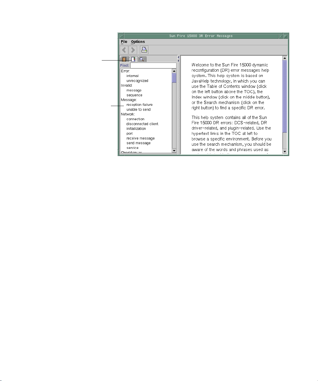
Index Button
Embedded Topics
FIGURE 5-2 JavaHelp Index Display
JavaHelp Search
The DR error messages help system provides a full-text search function. The search
database is constructed by the indexing of error message help files.
Before searching for a specific error message, search on a specific string of text in the
error message. Also, avoid using numeric values, as they are treated as replaceable
text. The error JavaHelp system window is shown below:
72 Sun Fire High-End and Midrange Systems Dynamic Reconfiguration User’s Guide • August 2005
Page 87

Search Button
FIGURE 5-3 JavaHelp Search Display
Replaceable Text
Chapter 5 SMS DR Procedures – From the SC (High-End Only) 73
Page 88

74 Sun Fire High-End and Midrange Systems Dynamic Reconfiguration User’s Guide • August 2005
Page 89

CHAPTER
6
DR Internals
This chapter contains information about how DR works, and is not essential for
those simply wishing to use DR. It is included here for more technical users who
might find it of value.
This chapter covers the following topics:
■ “Software Components on the Domain” on page 75
■ “Software Components on the SC (High-End Only)” on page 77
Software Components on the Domain
This section describes the DR-related software components that reside on the
domain and make DR operations possible.
Domain Configuration Server (High-End Only)
The domain configuration server (DCS) is a daemon process that runs on a high-end
system domain and is started by
received. A single instance of the DCS runs in each domain. The DCS accepts DR
requests from the domain configuration agent (DCA) that runs on the SC. After the
DCS accepts a DR operation, it performs the request and returns the results to the
DCA. See
“Domain Configuration Agent (DCA)” on page 78.
inetd(1M) when the first remote DR request is
75
Page 90

Note – In domains that run the Solaris 10 OS, the DCS has no entries in the
inetd.conf file. In domains running earlier versions of the Solaris software, DCS
does have an entry in inetd.conf. In this latter case, if you alter or remove the
sun-dr entry in inetd.conf, make the same change to the sun-dr entry in the
ipsecinit.conf file.
DR Driver
The DR driver on a high-end system consists of a platform independent driver
named dr and a platform-specific module, named drmach. On midrange systems,
the driver is sbd and the platform-specific module is sbdp. The DR driver uses
standard features of the Solaris software whenever possible to control DR
operations, and it calls the platform-specific module as needed. The DR driver is
responsible for creating minor nodes in the file system that are used as attachment
points for DR operations.
Reconfiguration Coordination Manager
The reconfiguration coordination manager (RCM) is a daemon process that
coordinates DR operations on resources that are present in the domain. The RCM
daemon uses generic application program interfaces (APIs) to coordinate DR
operations between DR initiators and RCM clients.
The RCM consumers consist of DR initiators, which request DR operations, and DR
clients, which react to DR requests. Normally, the DR initiator is the configuration
administration command, cfgadm(1M). However, it can also be a GUI such as Sun
Management Center.
The DR clients can be:
■ Software layers that export high-level resources comprised of one or more
hardware devices (for example, multipathing applications)
■ Applications that monitor DR operations (for example, Sun Management Center)
■ Entities on a remote system, such as the system controller on a server
76 Sun Fire High-End and Midrange Systems Dynamic Reconfiguration User’s Guide • August 2005
Page 91

System Events Framework
DR uses the Solaris system events framework to notify other software entities of the
occurrence of changes that result from a DR operation. DR accomplishes this by
sending DR events to the system event daemon, syseventd, which, in turn, sends
the events to the subscribers of DR events. For more information about the system
events daemon, see the syseventd(1M) man page.
Software Components on the SC (HighEnd Only)
This section describes the DR-related software components that reside on a high-end
system’s SC and make DR operations possible.
DR Administration Models
The available component list controls what administrative tasks can be performed,
based on the name and group identification of the user. A brief description of the
privileges model for each DR operation is given in
SC (High-End Only)” on page 51. For a detailed description of the privileges
required for each SMS command, see the System Management Services (SMS)
Administrator Guide.
“SMS DR Procedures – From the
DR Processes and Daemons
Various processes and daemons on the Sun Fire high-end system controller (SC)
work together to accomplish DR operations. The processes and/or daemons that are
used depends entirely on the point of execution of the DR operation. For instance, if
you execute the DR operation from the SC, the system uses several more processes
and/or daemons to accomplish the DR operation than it would if you executed the
DR operation from the domain.
For more information about the processes and daemons that reside on the domain,
see the other chapters in this document. For more information about the processes
and daemons that reside in the SMS software on the SC, see the System Management
Services (SMS) Administrator Guide for more information.
Chapter 6 DR Internals 77
Page 92

Domain Configuration Agent (DCA)
The domain configuration agent (DCA) enables applications such as Sun
Management Center and SMS to initiate DR operations on a Sun Fire high-end
system domain. The DCA runs on the SC and manages the DR communications
between software applications running on the SC and the domain configuration
server on the domain. An individual instance of the DCA runs on the SC for each
domain on the Sun Fire high-end system. For more information about the DCA, see
the System Management Services (SMS) Administrator Guide.
Note – If you alter or remove the sun-dr entry in the inetd.conf file, make the
same change to the sun-dr entry in the ipsecinit.conf file.
Platform Configuration Daemon (PCD) (High-End Only)
The platform configuration daemon (PCD) manages the configuration of each Sun
Fire high-end system through a collection of flat files that comprise the PCD
database. All changes to the configuration of the Sun Fire high-end system must go
through the PCD. For more information about the PCD, see the System Management
Services (SMS) Administrator Guide.
Domain X Server (DXS)
The domain x server (DXS) manages communication between the SC and the DR
module (drmach) on the domain. An individual instance of the DXS runs on the SC
for each domain on the Sun Fire high-end system. For more information about the
DXS, see the System Management Services (SMS) Administrator Guide.
78 Sun Fire High-End and Midrange Systems Dynamic Reconfiguration User’s Guide • August 2005
Page 93

APPENDIX
A
DR Command Summary
This chapter contains a summary of the main DR operations and commands. Most
common DR operations on high-end systems can be executed by the few SMS
commands shown or referred to here, and many high-end system users prefer them.
Caution – Executing a DR command improperly can disable your system. Do not
execute the commands in the following chart without executing the steps described
in other parts of this document. The information provided here is intended for use
only by experienced DR users.
TABLE A-1 DR Operation and Command Summary
DR Operation High-End System SMS Command cfgadm Command(s)
Display board state, type, and
condition
Display info about board slots and
components
Display high-end system board
status
Display midrange system board
status
Display boards available to a
domain
Display status of system boards in
a particular domain
Display class of a system or I/O
board
rcfgadm -la
-d domain_id
None prtdiag
See Chapter 5 cfgadm -a -v -s “select=
n/a cfgadm -a -v
See Chapter 5 cfgadm -l
See Chapter 5 cfgadm -a -v -s “select=
rcfgadm -d domain_id
-s “cols=ap_id:class”
cfgadm -la
class(sbd)”
class(sbd)”
cfgadm -s “cols=ap_id:class”
79
Page 94

TABLE A-1 DR Operation and Command Summary (Continued)
DR Operation High-End System SMS Command cfgadm Command(s)
To display classes associated with
attachment points
Test a system board rcfgadm -d domain_id
rcfgadm -a -d domain_id
-s “cols=ap_id:class”
cfgadm -a -s “cols=ap_id:class”
cfgadm -t ap_id
-t ap_id
Test an I/O board n/a See “To Test an I/O Board (Midrange
Only)” on page 33
Add a board to a domain addboard -d domain_id
board_id
cfgadm -v -c configure board_id
- or -
cfgadm -v -c configure ap_id
Delete a board from a domain deleteboard board_id cfgadm -v -c disconnect board_id
- or cfgadm -v -c disconnect ap_id
Move a board from one domain to
another
Configure a CPU on a system
board
Configure memory on a system
board
Unconfigure all CPUs and
memory on a system board
Track memory unconfiguration rcfgadm -a -d domain_id
See “To Move a Board” on
page 60
rcfgadm -c configure
-d domain_id SBx::cpuy
rcfgadm -c configure
-d domain_id SBx::memory
rcfgadm -c unconfigure
-d domain_id SBx
-s “select=type
(memory),
See “To Move a System Board Between
Domains” on page 42
cfgadm -c configure SBx::cpuy
cfgadm -c configure SBx::memory
cfgadm -c unconfigure SBx
cfgadm -a -s “select=type
(memory),
cols=ap_id:o_state:info”
cols=ap_id:o_state:info”
Unconfigure a system board with
permanent memory
Disconnect a system board or I/O
board
Connect PCI slot on I/O board rcfgadm -c connect
rcfgadm -c unconfigure
-d domain_id -y SBO
rcfgadm -c disconnect
-d domain_id board_id
cfgadm -c unconfigure -y SBO
cfgadm -c disconnect board_id
cfgadm -c connect pci_ap_id
-d domain_id pci_ap_id
Configure PCI slot on I/O board rcfgadm -c configure
cfgadm -c configure pci_ap_id
-d domain_id pci_ap_id
Disconnect PCI slot on I/O board rcfgadm -c disconnect
cfgadm -c disconnect pci_ap_id
-d domain_id pci_ap_id
Unconfigure PCI slot on I/O
board
rcfgadm -c unconfigure
-d domain_id pci_ap_id
cfgadm -c unconfigure pci_ap_id
80 Sun Fire High-End and Midrange Systems Dynamic Reconfiguration User’s Guide • August 2005
Page 95

APPENDIX
B
Troubleshooting
This chapter discusses common types of failure:
■ “Unconfigure Operation Failure” on page 81
■ “Configure Operation Failure” on page 87
The following are examples of cfgadm diagnostic messages. (Syntax error messages
are not included here.)
cfgadm: Configuration administration not supported on this machine
cfgadm: hardware component is busy, try again
cfgadm: operation: configuration operation not supported on this machine
cfgadm: operation: Data error: error_text
cfgadm: operation: Hardware specific failure: error_text
cfgadm: operation: Insufficient privileges
cfgadm: operation: Operation requires a service interruption
cfgadm: System is busy, try again
WARNING: Processor number failed to offline.
See the following man pages for additional error message detail: cfgadm(1M),
cfgadm_sbd(1M), cfgadm_pci(1M), and config_admin(3CFGADM).
Unconfigure Operation Failure
An unconfigure operation for a system board or I/O board can fail if the system is
not in a correct state when you begin the operation.
81
Page 96

System Board Unconfiguration Failures
■ Memory on a board is interleaved across boards before an attempt to unconfigure
the board.
■ A process is bound to a CPU before an attempt to unconfigure the CPU.
■ Memory remains configured on a system board before you attempt a CPU
unconfigure operation on that board (midrange systems only).
■ The memory on the board is configured (in use). See “Unable to Unconfigure
Memory on a Board With Permanent Memory” on page 83.
■ CPUs on the board cannot be taken off line. See “Unable to Unconfigure a CPU”
on page 84.
Cannot Unconfigure a Board Whose Memory Is Interleaved Across Boards
If you try to unconfigure a system board whose memory is interleaved across system
boards, the system displays an error message such as:
cfgadm: Hardware specific failure: unconfigure N0.SB2::memory: Memory is
interleaved across boards: /ssm@0,0/memory-controller@b,400000
Cannot Unconfigure a CPU to Which a Process is Bound
If you try to unconfigure a CPU to which a process is bound, the system displays an
error message such as the following:
cfgadm: Hardware specific failure: unconfigure N0.SB2::cpu3: Failed to off-line:
/ssm@0,0/SUNW,UltraSPARC-III
● Unbind the process from the CPU and retry the unconfigure operation.
82 Sun Fire High-End and Midrange Systems Dynamic Reconfiguration User’s Guide • August 2005
Page 97

Cannot Unconfigure a CPU Before All Memory is Unconfigured (Midrange Only)
All memory on a system board must be unconfigured before you try to unconfigure
a CPU. If you try to unconfigure a CPU before all memory on the board is
unconfigured, the system displays an error message such as:
cfgadm: Hardware specific failure: unconfigure N0.SB2::cpu0: Can’t unconfig cpu
if mem online: /ssm@0,0/memory-controller
● Unconfigure all memory on the board and then unconfigure the CPU.
Unable to Unconfigure Memory on a Board With Permanent Memory
To unconfigure the memory on a board that has permanent memory, move the
permanent memory pages to another board that has enough available memory to
hold them. Such an additional board must be available before the unconfigure
operation begins.
Memory Cannot Be Reconfigured
If the unconfigure operation fails with a message such as the following, the memory
on the board could not be unconfigured:
cfgadm: Hardware specific failure: unconfigure N0.SB0: No available memory
target: /ssm@0,0/memory-controller@3,400000
Add to another board enough memory to hold the permanent memory pages, and
then retry the unconfigure operation.
● Confirm the memory page cannot be moved.
Look for the word “permanent” in the listing.
# cfgadm -av -s “select=type(memory)”
Appendix B Troubleshooting 83
Page 98
Not Enough Available Memory
If the unconfigure fails with one of the messages below, removal of the board would
not leave enough available memory in the system.
cfgadm: Hardware specific failure: unconfigure N0.SB0: Insufficient memory
cfgadm: Hardware specific failure: unconfigure N0.SB0: Memory operation failed
● Reduce the memory load on the system and try again; if practical, install more
memory in another board slot.
Memory Demand Increased
If the unconfigure fails with the following message, the memory demand has
increased while the unconfigure operation was proceeding:
cfgadm: Hardware specific failure: unconfigure N0.SB0: Memory operation refused
● Reduce the memory load on the system and try again.
Unable to Unconfigure a CPU
CPU unconfiguration is part of the unconfiguration operation for a
system board. If the operation fails to take the CPU offline, the following message is
logged to the console:
WARNING: Processor number failed to offline.
This failure occurs if:
■ The CPU has processes bound to it.
■ The CPU is the last one in a CPU set.
■ The CPU is the last online CPU in the system.
84 Sun Fire High-End and Midrange Systems Dynamic Reconfiguration User’s Guide • August 2005
Page 99

Unable to Disconnect a Board
It is possible to unconfigure a board and then discover that it cannot be
disconnected. The cfgadm status display lists the board as not detachable. This
problem occurs when the board is supplying an essential hardware service that
cannot be relocated to an alternate board.
I/O Board Unconfiguration Failure
A device cannot be unconfigured or disconnected while it is in use. Many failures to
unconfigure I/O boards occur because activity on the boards has not been stopped,
or because an I/O device becomes active again after it has been stopped.
Device Busy
Disks attached to an I/O board must be idled before you attempt to unconfigure or
disconnect that board. Any attempt to unconfigure/disconnect a board whose
devices are still in use is rejected.
If an unconfiguration operation fails because an I/O board has a busy or open
device, the board is left only partially unconfigured. The operation sequence stopped
at the busy device.
To regain access to the devices that were not unconfigured, the board must be
completely unconfigured, then reconfigured.
If a device on the board is busy, the system logs a message such as the following
after an attempt to unconfigure:
cfgadm: Hardware specific failure: unconfigure N0.IB6: Device
busy: /ssm@0,0/pci@18,700000/pci@1/SUNW,isptwo@4/sd@6,0
To continue the unconfigure operation, unmount the device and retry the
unconfigure operation. The board must be in the unconfigured state before you try
to reconfigure this board.
Problems with I/O Devices
1. Use the fuser(1M) command to identify the processes that have these devices
open.
Appendix B Troubleshooting 85
Page 100
2. Kill the vold daemon gracefully.
# /etc/init.d/volmgt stop
3. Disconnect all SCSI controllers that are associated with the card you are trying to
unconfigure.
To get a list of all connected SCSI controllers use the following command.
# cfgadm -l -s "select=class(scsi)"
4. If the redundancy features of Solaris Volume Manager mirroring are used to
access a device connected to the board, reconfigure these subsystems so that the
device or network is accessible by way of controllers on other system boards.
5. Unmount file systems, including volume manager meta-devices that have a board
resident partition.
# umount/partition
6. Remove the volume manager database from board-resident partitions.
The location of the volume manager database is explicitly chosen by the user and
can be changed.
7. Remove any private regions used by Solaris Volume Manager or Veritas Volume
Manager.
Solaris Volume Manager by default uses a private region on each device that it
controls, so such devices must be removed from Solaris Volume Manager control
before they can be detached.
8. Remove disk partitions from the swap configuration.
9. Either kill any process that directly opens a device or raw partition, or direct it to
close the open device on the board.
Note – Unmounting file systems might affect NFS client systems.
86 Sun Fire High-End and Midrange Systems Dynamic Reconfiguration User’s Guide • August 2005
 Loading...