

Page 1

Sun Fire™880 Server
Rackmounting Guide
Sun Microsystems, Inc.
901 San Antonio Road
Palo Alto, CA 94303-4900 U.S.A.
650-960-1300
Part No. 806-6594-10
August 2001, Revision A
Send comments about this document to: [email protected]
Page 2

Copyright 2001Sun Microsystems,Inc., 901San AntonioRoad, PaloAlto, CA94303-4900 U.S.A.All rightsreserved.
This productor documentis distributedunder licensesrestricting its use, copying, distribution, and decompilation. No part of this product or
document maybe reproduced inany formby anymeans withoutprior writtenauthorization ofSun andits licensors,if any.Third-party
software, includingfont technology, iscopyrighted andlicensed fromSun suppliers.
Parts ofthe productmay bederived from BerkeleyBSD systems,licensed fromthe Universityof California.UNIX isa registered trademark in
the U.S.and othercountries, exclusivelylicensed throughX/Open Company, Ltd.
Sun, SunMicrosystems, theSun logo,AnswerBook, AnswerBook2,docs.sun.com, SunEnterprise, SunFire, OpenBoot, SunSwift, Sun
Enterprise SyMON,SunVTS, andSolaris aretrademarks, registered trademarks,or servicemarks ofSun Microsystems, Inc. in the U.S. and
other countries.All SPARC trademarks are used under license and are trademarks or registered trademarks of SPARC International, Inc.in the
U.S. andother countries.Products bearingSPARC trademarks arebased uponan architecture developedby SunMicrosystems, Inc.
The OPENLOOK andSun™ GraphicalUser Interfacewas developedby SunMicrosystems, Inc.for itsusers andlicensees. Sunacknowledges
the pioneeringefforts ofXerox in researchingand developingthe conceptof visualor graphicaluser interfacesfor thecomputer industry. Sun
holds anon-exclusive licensefrom Xerox tothe XeroxGraphical UserInterface, whichlicense alsocovers Sun’s licensees who implement OPEN
LOOK GUIsand otherwisecomply withSun’s writtenlicense agreements.
Federal Acquisitions:Commercial Software—Government UsersSubject toStandard LicenseTerms and Conditions.
DOCUMENTATION IS PROVIDED “AS IS” AND ALL EXPRESS OR IMPLIED CONDITIONS, REPRESENTATIONS AND WARRANTIES,
INCLUDING ANY IMPLIED WARRANTY OF MERCHANTABILITY, FITNESS FOR APARTICULAR PURPOSE OR NON-INFRINGEMENT,
ARE DISCLAIMED, EXCEPT TO THE EXTENT THAT SUCH DISCLAIMERS ARE HELD TO BE LEGALLY INVALID.
Copyright 2001Sun Microsystems,Inc., 901San AntonioRoad, PaloAlto, CA94303-4900 Etats-Unis.Tous droits réservés.
Ce produitou documentest distribuéavec deslicences quien restreignent l’utilisation,la copie,la distribution,et ladécompilation. Aucune
partie dece produitou documentne peutêtre reproduite sousaucune forme,par quelquemoyen quece soit,sans l’autorisationpréalable et
écrite deSun etde sesbailleurs delicence, s’ily ena. Lelogiciel détenupar destiers, etqui comprendla technologierelative aux polices de
caractères, estprotégé par un copyright et licencié par des fournisseurs de Sun.
Des partiesde ceproduit pourront êtredérivées dessystèmes BerkeleyBSD licenciéspar l’Universitéde Californie.UNIX estune marque
déposée auxEtats-Unis etdans d’autrespays etlicenciée exclusivementpar X/OpenCompany, Ltd.
Sun, SunMicrosystems, lelogo Sun,AnswerBook, AnswerBook2,docs.sun.com, SunEnterprise, SunFire, OpenBoot, SunSwift, Sun Enterprise
SyMON, SunVTS,et Solarissont desmarques defabrique oudes marques déposées,ou marquesde service,de SunMicrosystems, Inc. aux
Etats-Unis etdans d’autrespays. Toutes les marques SPARC sont utiliséessous licenceet sontdes marques de fabrique ou des marques
déposées deSPARC International, Inc. aux Etats-Unis et dans d’autrespays. Lesproduits portant les marques SPARC sont baséssur une
architecture développée par Sun Microsystems, Inc.
L’interfaced’utilisation graphiqueOPEN LOOKet Sun™a étédéveloppée parSun Microsystems, Inc. pour ses utilisateurs etlicenciés. Sun
reconnaît lesefforts de pionniers de Xerox pour la recherche et le développement du concept des interfaces d’utilisation visuelle ou graphique
pour l’industriede l’informatique.Sun détientune licencenon exclusivede Xeroxsur l’interfaced’utilisation graphiqueXerox, cette licence
couvrant égalementles licenciésde Sunqui mettenten placel’interface d’utilisationgraphique OPENLOOK etqui enoutre seconforment aux
licences écritesde Sun.
LA DOCUMENTATION EST FOURNIE “EN L’ETAT” ET TOUTES AUTRES CONDITIONS, DECLARATIONS ET GARANTIES EXPRESSES
OU TACITES SONT FORMELLEMENTEXCLUES, DANSLA MESUREAUTORISEE PARLA LOIAPPLICABLE, YCOMPRIS NOTAMMENT
TOUTE GARANTIE IMPLICITE RELATIVE A LA QUALITE MARCHANDE, A L’APTITUDE A UNE UTILISATION PARTICULIERE OU A
L’ABSENCE DE CONTREFAÇON.
Please
Recycle
Page 3

Contents
Preface v
1. Getting Started 1
Unpacking the Kit 1
Inventory 2
What Next 3
2. Installing the Server Into the Cabinet 5
Before You Begin 6
Safety and System Performance Cautions 6
Tools, Equipment, and Documentation Required 7
Preparing the Server 8
Remove Components 8
Overview of Parts to Be Removed From the Chassis 9
Remove the Handle From Each Side Door 10
Remove the Fenders and Lower Side Panels 12
Install the Lifting Handles 15
Attach the Server Cable Management Bracket 16
Preparing the Cabinet 17
Installing the Tray Assembly Into the Cabinet 17
iii
Page 4

Adjust the Rear Brackets 17
Determine the Vertical Position of the Server in the Cabinet 19
Attach the Tray Assembly to the Cabinet 20
Installing the Server Into the Tray Assembly 23
Restoring the Server 27
Securing the Server in the Cabinet 28
Installing Trim Strips 29
Restoring the Cabinet 30
Managing Cables 30
Attach the Cable Management Bracket to the Cabinet 31
What Next 32
A. Cabinet Requirements 33
iv Sun Fire 880 Server Rackmounting Guide • August 2001
Page 5

Preface
The Sun Fire 880 Server Rackmounting Guide provides instructions for installing the
Sun Fire™ 880 server into an EIA-compliant cabinet.
After you install the server into the cabinet, consult the Sun Fire 880 Server Owner’s
Guide for information about connecting the power cords, network cables, and I/O
interface cables and installing the Solaris operating environment software.
How This Book Is Organized
The chapters in this book are organized as follows:
Chapter 1 describes the contents of the rackmounting kit.
Chapter 2 provides step-by-step instructions for installing the server into an
EIA-compliant cabinet.
Appendix A lists the requirements of a cabinet used to rackmount the server.
v
Page 6

Related Documentation
Application Title
Configuration and setup Sun Fire 880 Server Owner’s Guide
Parts replacement and service Sun Fire 880 Server Service Manual
Accessing Sun Documentation Online
A broad selection of Sun system documentation is located at:
http://www.sun.com/products-n-solutions/hardware/docs
A complete set of Solaris documentation and many other titles are located at:
http://docs.sun.com
Ordering Sun Documentation
Fatbrain.com, an Internet professional bookstore, stocks select product
documentation from Sun Microsystems, Inc.
For a list of documents and how to order them, visit the Sun Documentation Center
on Fatbrain.com at:
http://www.fatbrain.com/documentation/sun
vi Sun Fire 880 Server Rackmounting Guide • August 2001
Page 7

Sun Welcomes Your Comments
Sun is interested in improving its documentation and welcomes your comments and
suggestions. You can email your comments to Sun at:
Please include the part number (806-6594-10) of your document in the subject line of
your email.
Preface vii
Page 8

viii Sun Fire 880 Server Rackmounting Guide • August 2001
Page 9

CHAPTER
1
Getting Started
This guide shows you how to install the Sun Fire 880 server into a 19-inch (48.26-cm)
wide Electronic Industries Association (EIA)-compliant rack or cabinet. After you
install the server into the cabinet according to the instructions in this guide, see the
Sun Fire 880 Server Owner’s Guide for information about system setup and software
installation.
To install the server into a cabinet, complete the following tasks:
■ Unpack and verify the contents of the rackmounting kit. See “Unpacking the Kit”
on page 1 and “Inventory” on page 2.
■ Install the server into the cabinet. See Chapter 2.
Note – To illustrate the procedures, this guide shows the server being installed into
a Sun MicrosystemsTMcabinet.
Unpacking the Kit
The rackmounting kit is shipped from the factory in one carton.
Inspect the shipping carton for physical damage. If the carton is damaged, request
that the carrier ’s agent be present when the carton is opened. Keep all contents and
packing material for the agent’s inspection.
Check that you received the complete kit. See “Inventory” on page 2. Contact Sun
Microsystems or your distributor/reseller if any parts are missing.
1
Page 10
Inventory
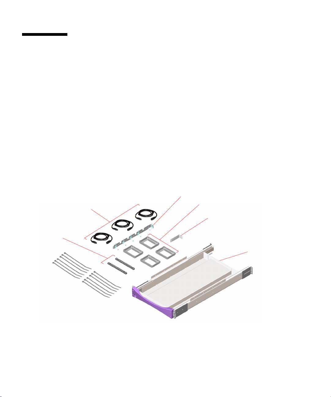
You will need one rackmounting kit for each Sun Fire 880 server you intend to install
into a cabinet. Each rackmounting kit contains the following parts:
■ Tray assembly
■ Cable management bracket for the server
■ Cable management bracket for the cabinet
■ Power jumper cords (3)
■ Lifting handles (4)
■ Trim strips (2)
■ Tie wraps
■ Screws
■ Sun Fire 880 Server Rackmounting Guide
Power jumper cords (3)
Cable management
bracket for server
Lifting handles (4)
Cable management
bracket for cabinet
Trim strips (2)
Tie
wraps
2 Sun Fire 880 Server Rackmounting Guide • August 2001
Tray assembly
Page 11
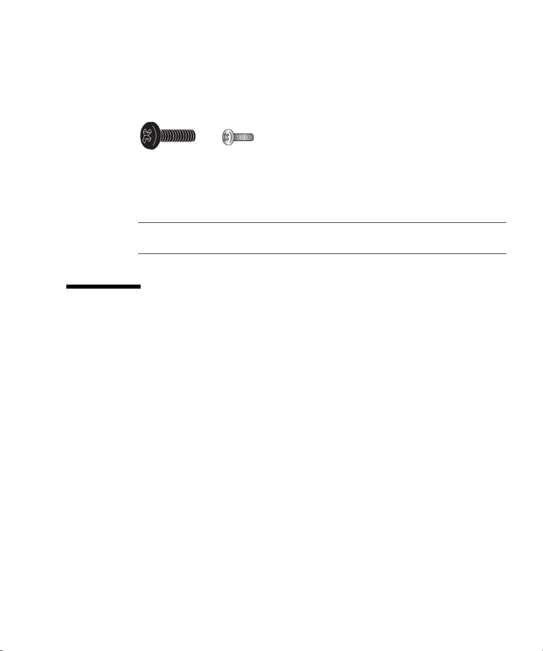
The kit contains a plastic bag holding 10-32 screws (black in color) and M4 screws.
You will use these screws to install the tray assembly and server into the cabinet.
The following figure shows the screws at actual size.
10-32 screw M4 screw
(Black in color)
Any screws not used in the rack installation are spares.
Note – Bar nuts are required (but not included) for non-threaded cabinets. See the
cabinet instructions for more information.
What Next
Go to Chapter 2 and complete the procedures for installing the server into the
cabinet.
Chapter 1 Getting Started 3
Page 12

4 Sun Fire 880 Server Rackmounting Guide • August 2001
Page 13

CHAPTER
2
Installing the Server Into the Cabinet
This chapter provides step-by-step instructions for installing the Sun Fire 880 server
into a 19-inch (48.26-cm) wide EIA-compliant cabinet.
To install a Sun Fire 880 server into the cabinet, complete the following tasks in the
order listed:
■ Make sure you have completed the prerequisite tasks. See “Before You Begin” on
page 6.
■ Prepare the server. See “Preparing the Server” on page 8.
■ Prepare the cabinet. See “Preparing the Cabinet” on page 17.
■ Install the tray assembly into the cabinet. See “Installing the Tray Assembly Into
the Cabinet” on page 17.
■ Install the server into the tray assembly. See “Installing the Server Into the Tray
Assembly” on page 23.
■ Make the server ready for operation. See “Restoring the Server” on page 27.
■ Secure the tray handle to the cabinet rails. See “Securing the Server in the
Cabinet” on page 28.
■ Install the trim strips. See “Installing Trim Strips” on page 29.
■ Replace the front and back doors of the cabinet. See “Restoring the Cabinet” on
page 30.
■ Develop the cable management scheme. See “Managing Cables” on page 30.
5
Page 14
Before You Begin
Before you begin the installation procedures, complete the following tasks:
■ Verify that your cabinet meets the requirements described in Appendix A.
■ Check “Safety and System Performance Cautions” on page 6 and make sure your
installation plan reflects the measures described.
■ Check the documentation provided with your cabinet and make sure your
installation plan reflects the cautionary measures described.
■ Unpack the rackmounting kit and verify that you have all the components and
hardware shown in Chapter 1.
■ Gather the required tools. See “Tools, Equipment, and Documentation Required”
on page 7.
Safety and System Performance Cautions
Adhere to the following cautions when installing a Sun Fire 880 server into a cabinet.
For a complete description of the safety cautions to follow when installing a server,
see the Sun Fire 880 Server Owner’s Guide.
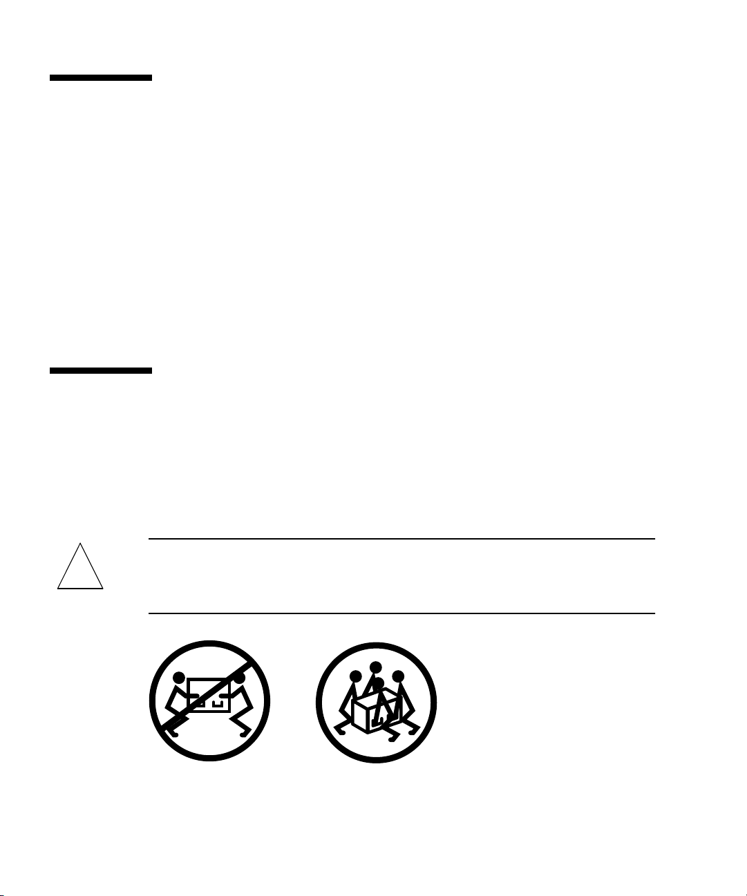
Caution – Do not attempt to lift the server until you remove all CPU/Memory
!
6 Sun Fire 880 Server Rackmounting Guide • August 2001
boards, all power supplies, all CPU fan trays, and all I/O fan trays. Once these
components are removed, four persons are required to lift the server. See “Preparing
the Server” on page 8 for information about removing these components.
Page 15
Caution – Be sure the cabinet is stabilized so that the it cannot move or tip forward
!
!
!
!
when one or more systems or devices are fully extended from the front of the
cabinet. The cabinet must be bolted securely to the floor or equipped with a sturdy
and extendable anti-tip leg. If there are feet beneath the cabinet to prevent it from
rolling, be sure the feet are fully extended downward to the floor. See the
instructions provided with the cabinet.
Caution – Install the server as low as possible in the cabinet. For best stability, do
not install the server above equipment that weighs less than the server. If you will be
installing two servers in a cabinet, install the lower server first.
Caution – To prevent the cabinet from tipping forward, do not attempt to roll or
move the cabinet after installing the server in the cabinet.
Caution – For proper ventilation and cooling of the server, be sure the cabinet and
the operating location comply with the requirements given in Appendix A.
Tools, Equipment, and Documentation Required
The following tools, equipment, and documentation are required when
rackmounting the server:
■ Phillips No. 2 screwdriver
■ Phillips No. 1 screwdriver
■ Level
■ Flat blade screwdriver
■ Adjustable wrench
■ Masking tape or felt tip pen
■ Antistatic wrist strap
■ Antistatic mat
■ Sun Fire 880 Server Owner’s Guide
■ Sun Fire 880 Server Service Manual
Chapter 2 Installing the Server Into the Cabinet 7
Page 16

Preparing the Server
To prepare the server for rackmounting, complete the following tasks:
■ Power off the system and disconnect the server’s power cords, network cables,
and I/O cables. See the Sun Fire 880 Server Service Manual for instructions.
■ Remove all power supplies, CPU/Memory boards, I/O fan trays, and CPU fan
trays. See “Remove Components” on page 8.
■ Remove the side door handles. See “Remove the Handle From Each Side Door”
on page 10.
■ Remove the fenders and lower side panels. See “Remove the Fenders and Lower
Side Panels” on page 12.
■ Install the lifting handles. See “Install the Lifting Handles” on page 15.
■ Attach the cable management bracket to the back of the server. See “Attach the
Server Cable Management Bracket” on page 16.
Remove Components
In order for four persons to lift the server safely, you must reduce the weight of the
server before you attempt to install it into the cabinet. To reduce the weight of the
server, remove the following components:
■ All power supplies
■ All CPU/Memory boards
■ All CPU fan trays
■ All I/O fan trays
See the Sun Fire 880 Server Service Manual for component removal procedures.
8 Sun Fire 880 Server Rackmounting Guide • August 2001
Page 17
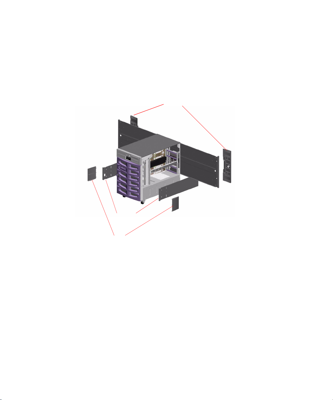
Overview of Parts to Be Removed From the Chassis
The following figure identifies the parts that you must remove from the chassis
before you can install the server into the cabinet.
Side door
handles
Lower side
panels
Fenders
The following sections provide detailed information about removing each part.
Chapter 2 Installing the Server Into the Cabinet 9
Page 18
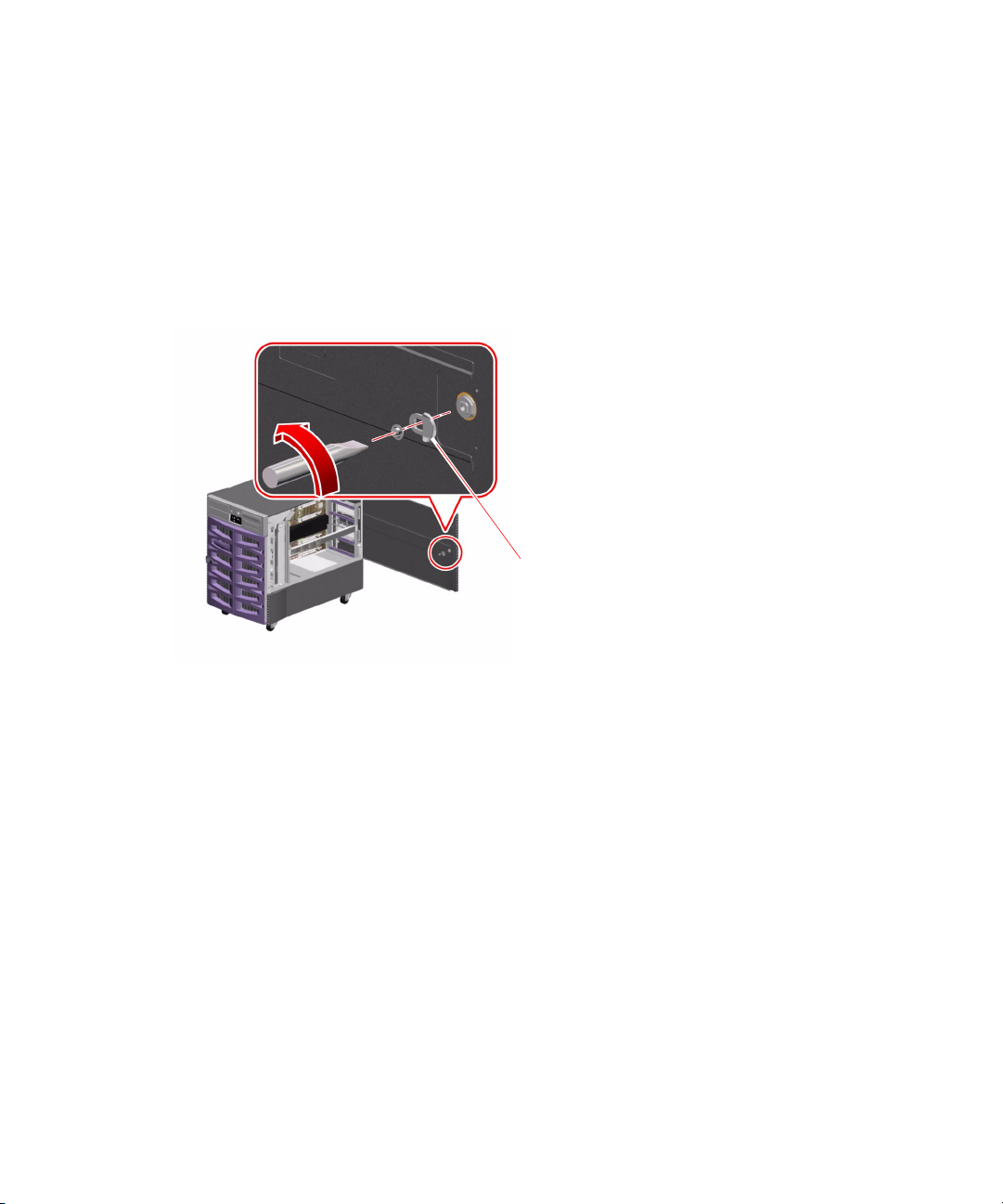
Remove the Handle From Each Side Door
1. Open one of the server’s side doors.
Use the key provided with the server to unlock the door.
2. Remove the pawl from the side door.
On the inside of the door, remove the slot head screw from the center of the pawl.
Pull the pawl straight out to remove it.
Pawl
10 Sun Fire 880 Server Rackmounting Guide • August 2001
Page 19
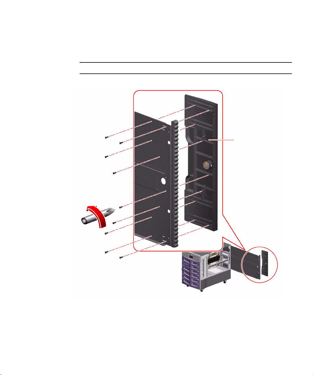
3. Remove the side door handle.
Remove the nine screws from the inside of the door.
From the outside of the door, pull the handle straight out to remove it.
Note – The lock remains in the handle.
Side door handle
4. Repeat steps 1 through 3 for the other side door.
5. Place the handles, pawls, and screws into the kit carton for safekeeping. You will
need to reinstall these parts if you reconfigure the server as a deskside unit.
Chapter 2 Installing the Server Into the Cabinet 11
Page 20
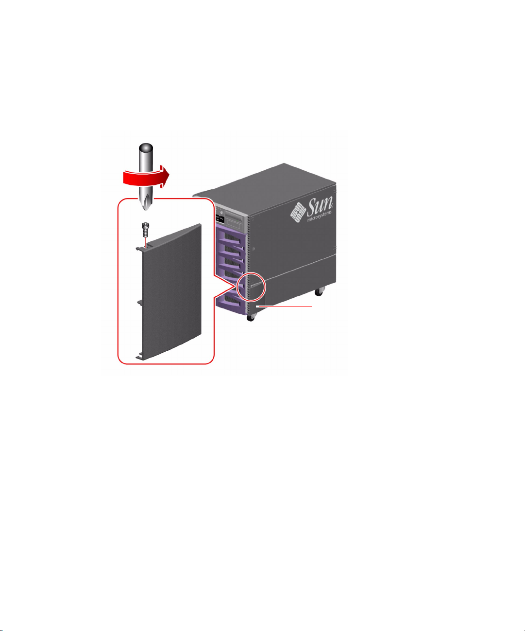
Remove the Fenders and Lower Side Panels
1. Remove the fender from the front of each of the lower side panels.
a. Remove the screw from the top of the fender.
Fender
b. Grasp the top and bottom edges of the fender and carefully flex the fender to
remove it.
c. Repeat steps a and b to remove the fender from the other lower side panel.
12 Sun Fire 880 Server Rackmounting Guide • August 2001
Page 21
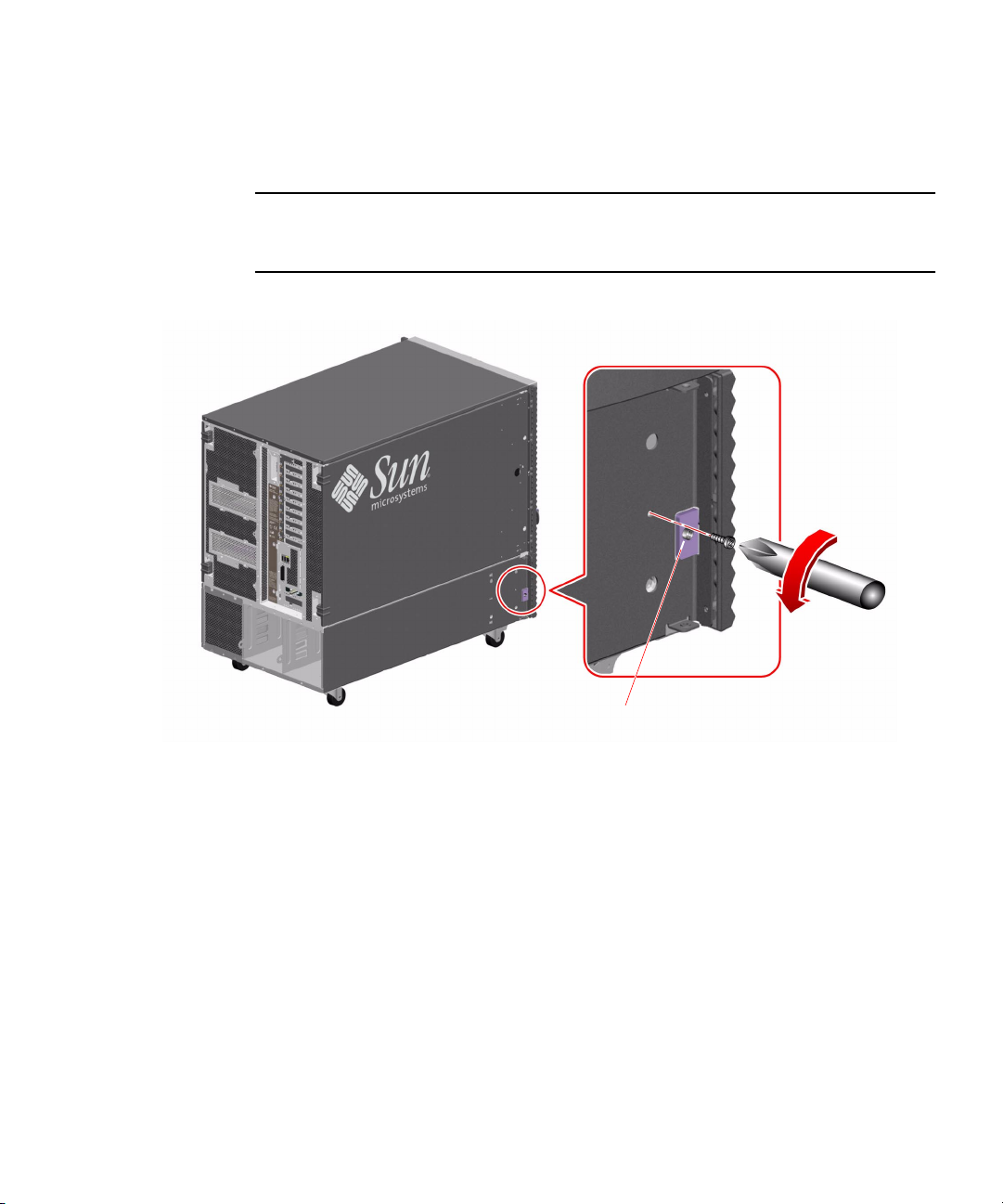
2. Remove the lower side panel from the left side of the server.
Remove the screw located approximately 3 inches (8 cm) from the front of the lower
side panel.
Note – On the left side of the server, do not remove the screw that attaches the small
bracket to the side of the server. Removing this screw prevents the front door from
closing securely.
Do not remove this screw.
Chapter 2 Installing the Server Into the Cabinet 13
Page 22
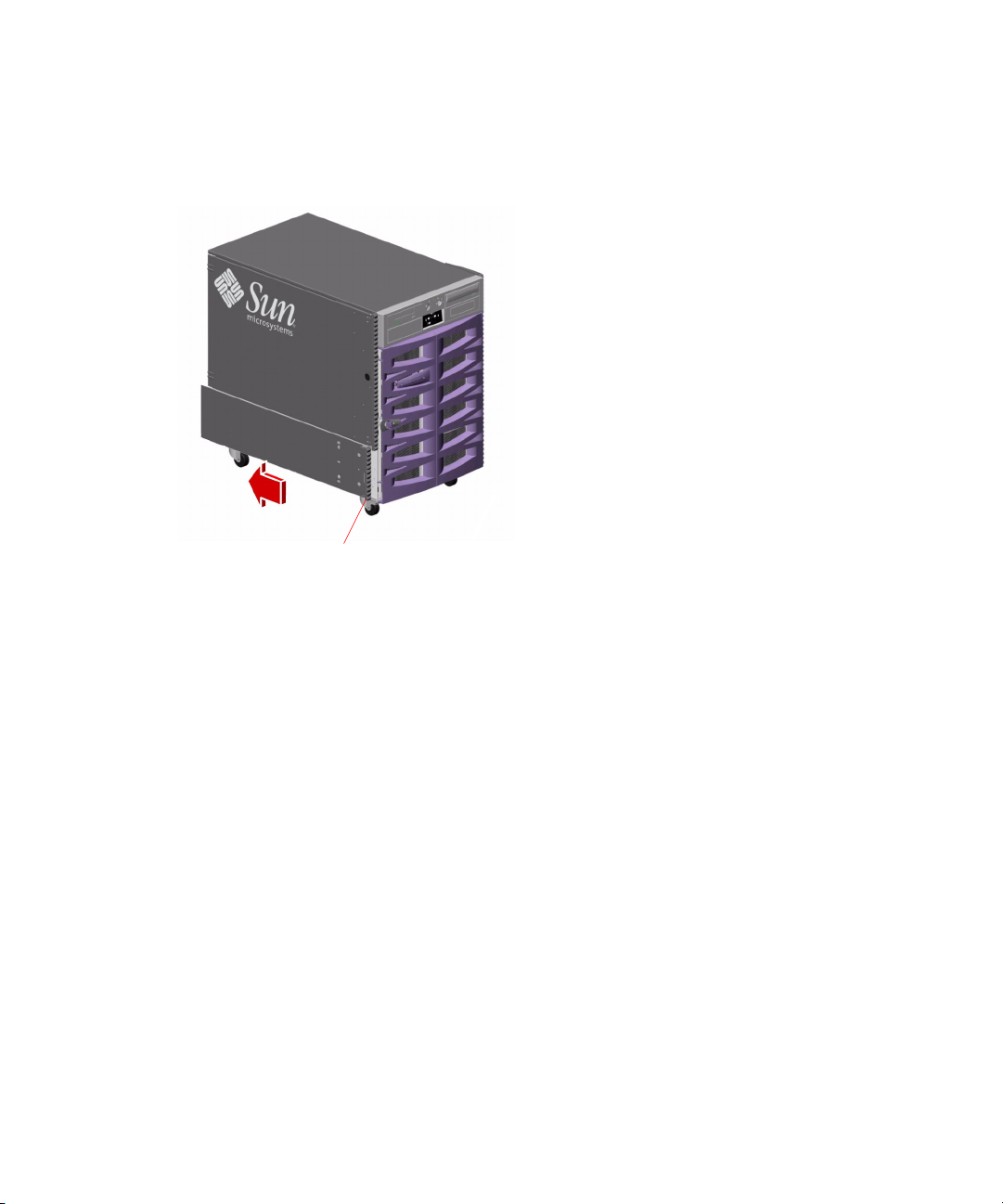
3. Grasp the trim strip and slide the lower side panel toward the rear of the server.
The lower side panel should disengage as you slide the panel so that you can easily
remove it.
Trim strip
4. Repeat steps 2 and 3 for the right lower side panel.
5. Place the fenders, lower side panels, and screws into the kit carton for
safekeeping.
You will need to reinstall these parts if you reconfigure the server as a deskside unit.
14 Sun Fire 880 Server Rackmounting Guide • August 2001
Page 23
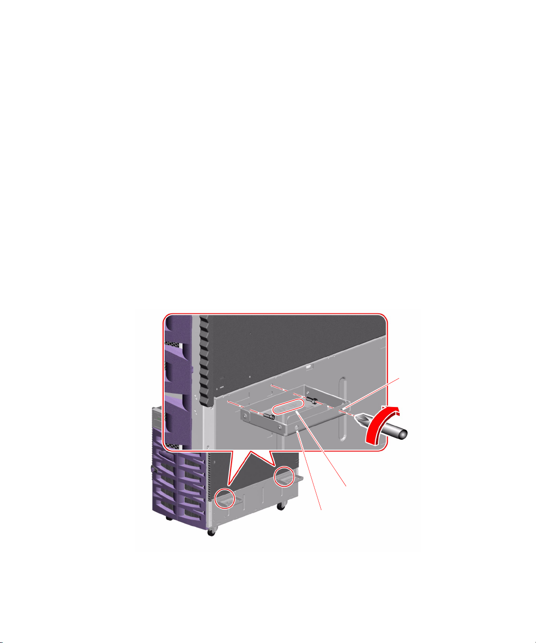
Install the Lifting Handles
1. Locate the four lifting handles provided with the rackmounting kit.
2. Install two lifting handles on one side of the server using two M4 screws to attach
each handle to the lower side of the server.
a. With the “THIS SIDE UP” label facing upward, insert the screwdriver through
one of the access holes on the outside of the handle.
Using the access hole makes it easier to reach the screw hole on the inside of the
handle.
b. Position the screw on the inside of the handle in the hole that is opposite the
access hole.
c. Attach the handle to the server using the appropriate screw hole just below the
server side door. See the following figure.
d. Finish installing the handle by repeating the procedure using the second access
hole on the outside of the handle.
e. Repeat steps a through d for the second handle.
Access hole
“THIS SIDE UP” label
Access hole
3. Repeat step 2 to install two handles on the other side of the server.
Chapter 2 Installing the Server Into the Cabinet 15
Page 24
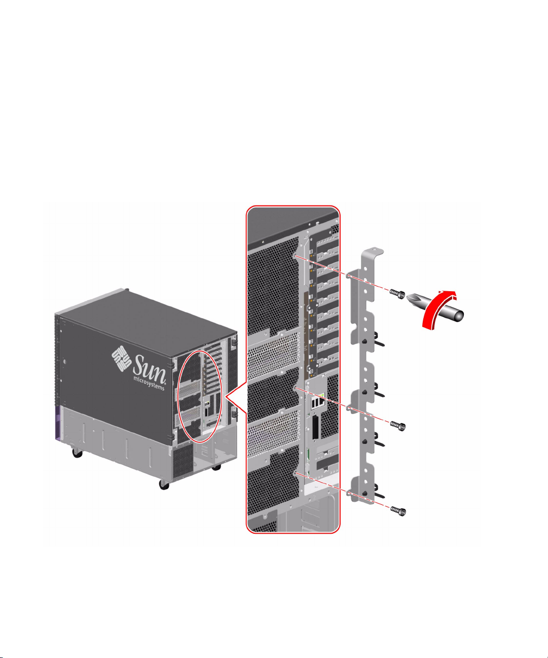
Attach the Server Cable Management Bracket
The cable management bracket that attaches to the back of the server may help to
provide strain relief for the cables. See “Managing Cables” on page 30 for general
cable management guidelines.
1. Locate the server cable management bracket provided with the rackmounting kit.
2. Attach the cable management bracket to the back of the server.
Attach the cable management bracket using three M4 screws as shown in the
following figure.
16 Sun Fire 880 Server Rackmounting Guide • August 2001
Page 25

Preparing the Cabinet
Make sure the operating location complies with the Sun Fire 880 server requirements
and the requirements of the cabinet. See Appendix A of this guide and the cabinet
documentation for information.
1. Be sure the cabinet is stabilized so that the cabinet cannot move or tip forward.
If there are feet beneath the cabinet to prevent it from rolling, be sure the feet are
fully extended downward to the floor.
Stabilize the cabinet using the stabilizing mechanisms provided with the cabinet.
See the instructions provided with the cabinet.
2. Open the front and rear doors.
See the instructions provided with the cabinet.
3. Remove (if applicable) the front and rear doors and the side panels of the cabinet.
See the instructions provided with the cabinet.
Installing the Tray Assembly Into the Cabinet
To install the tray assembly into the cabinet, complete these tasks:
■ If necessary, adjust the rear brackets on the tray assembly slides for the depth of
the cabinet.
■ Determine the vertical position of the server in the cabinet.
■ Attach the tray assembly to the cabinet rails.
Adjust the Rear Brackets
1. Measure the depth of the cabinet.
Measure the depth of the cabinet from the outside face of the front rail to the outside
face of the rear rail. The tray assembly and server can be installed into a 19-inch
(48.3-cm) cabinet with a depth of at least 32 inches (81.3 cm) and not more than
36 inches (91.4 cm).
Chapter 2 Installing the Server Into the Cabinet 17
Page 26
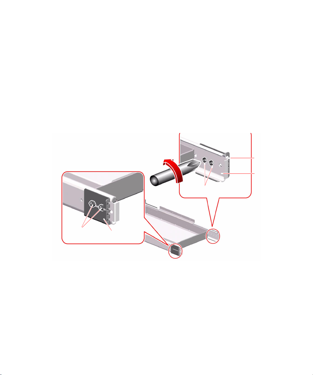
2. Measure the length of each slide.
Measure the distance from the inside face of the front bracket to the inside face of
the rear bracket. If this measurement is longer or shorter than the cabinet’s depth,
which you measured in step 1, you must adjust the rear bracket on each slide to
accommodate the depth of the cabinet.
3. If required, adjust the rear bracket on each slide.
a. Extend the tray assembly until you can see the two 10-32 screws located on the
inside rear of each outer slide.
The screws on the inside of the outer slide (and the lock nuts on the outside of the
bracket) secure the rear bracket to the outer slide.
b. Loosen the two 10-32 screws and the lock nuts.
10-32 screws
Rear
bracket
Outer
slide
Lock nuts
Rear bracket
c. Slide each rear bracket forward or backward as required to accommodate the
depth of the cabinet.
Slide each rear bracket and measure the distance from the inside face of the front
bracket to the inside face of the rear bracket.
Continue to slide the rear bracket and measure the distance from the inside face
of the front bracket to the inside face of the rear bracket until the measurement
equals the depth of the cabinet, which you measured in step 1.
18 Sun Fire 880 Server Rackmounting Guide • August 2001
Page 27

Note – Four screw holes are provided in the outer slide. Depending on the cabinet
depth, you may need to move one (or both) of the 10-32 screws to another of the
four screw holes. Be sure to use both screws to secure each rear bracket to the outer
slide.
d. Tighten the two 10-32 screws and lock nuts on each slide to resecure the rear
brackets to the outer slides.
Determine the Vertical Position of the Server in the Cabinet
Plan to install the tray assembly in the lowest available position in the cabinet. If you
are installing two Sun Fire 880 servers in the cabinet, install the lower server first.
To determine the vertical position of the server, identify which cabinet rail holes to
use for attaching the front and rear brackets by completing the following steps:
1. Locate and mark the correct holes on the right and left front vertical cabinet rails.
Make sure there is enough vertical space to install the server.
Note – Each Sun Fire 880 server requires 17 rack units (29.75 inches) or 51 holes on
the vertical rails of the cabinet. A standard 72-inch high cabinet can accommodate
two Sun Fire 880 servers.
If the Sun Fire 880 server will be installed immediately above a power sequencer,
leave at least one free hole above the sequencer.
Using masking tape or a felt tip pen, mark the lowest available hole for installing the
tray on the right front vertical rail of the cabinet. The second free hole is the lowest
available hole if you are installing the Sun Fire 880 server immediately above a
power sequencer.
Mark the matching hole on the left front rail of the cabinet. Count the holes to be
sure you are using matching holes on the right and left rails of the cabinet.
2. Locate and mark the corresponding holes on the right and left rear vertical cabinet
rails.
Using masking tape or a pen, mark the matching holes on the right and left rear
vertical rails.
Count the holes to be sure you are using the holes that match the ones you marked
in step 1.
Chapter 2 Installing the Server Into the Cabinet 19
Page 28
Attach the Tray Assembly to the Cabinet
Using the rail holes you marked in “Determine the Vertical Position of the Server in
the Cabinet” on page 19, attach the tray assembly to the cabinet by completing the
following steps:
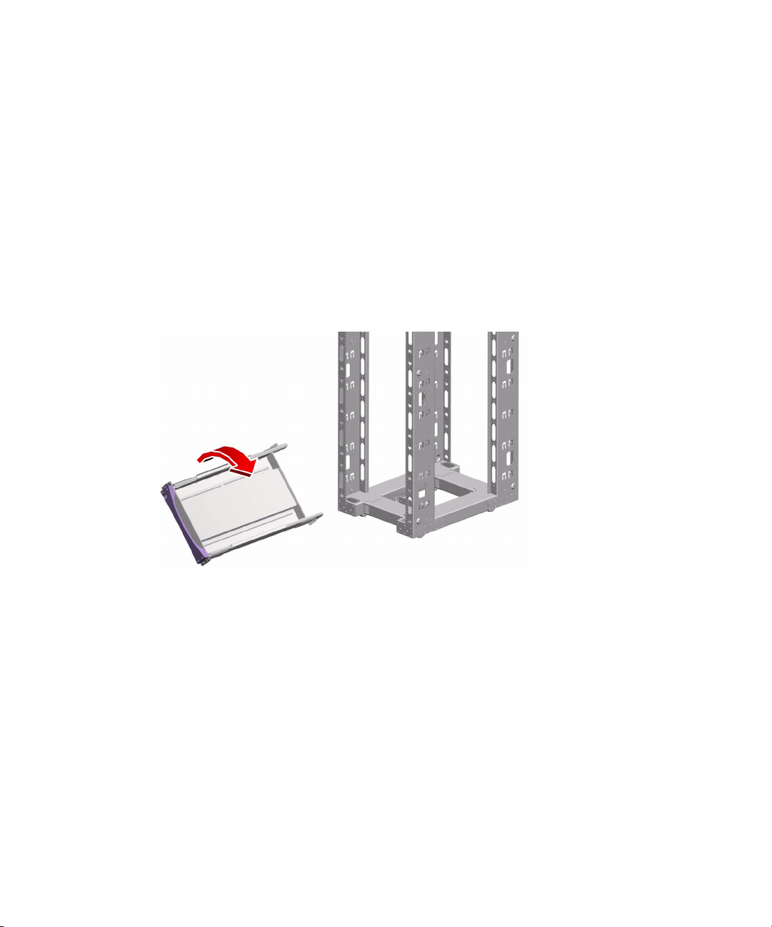
1. Attach the front brackets on the slides of the tray assembly to the front rails of the
cabinet.
a. With the help of an assistant, position the tray assembly on the inside of the
cabinet with the front brackets at the front of the cabinet.
To fit the tray assembly between the rails, you will need to tilt it by lowering one
side of the assembly.
20 Sun Fire 880 Server Rackmounting Guide • August 2001
Page 29
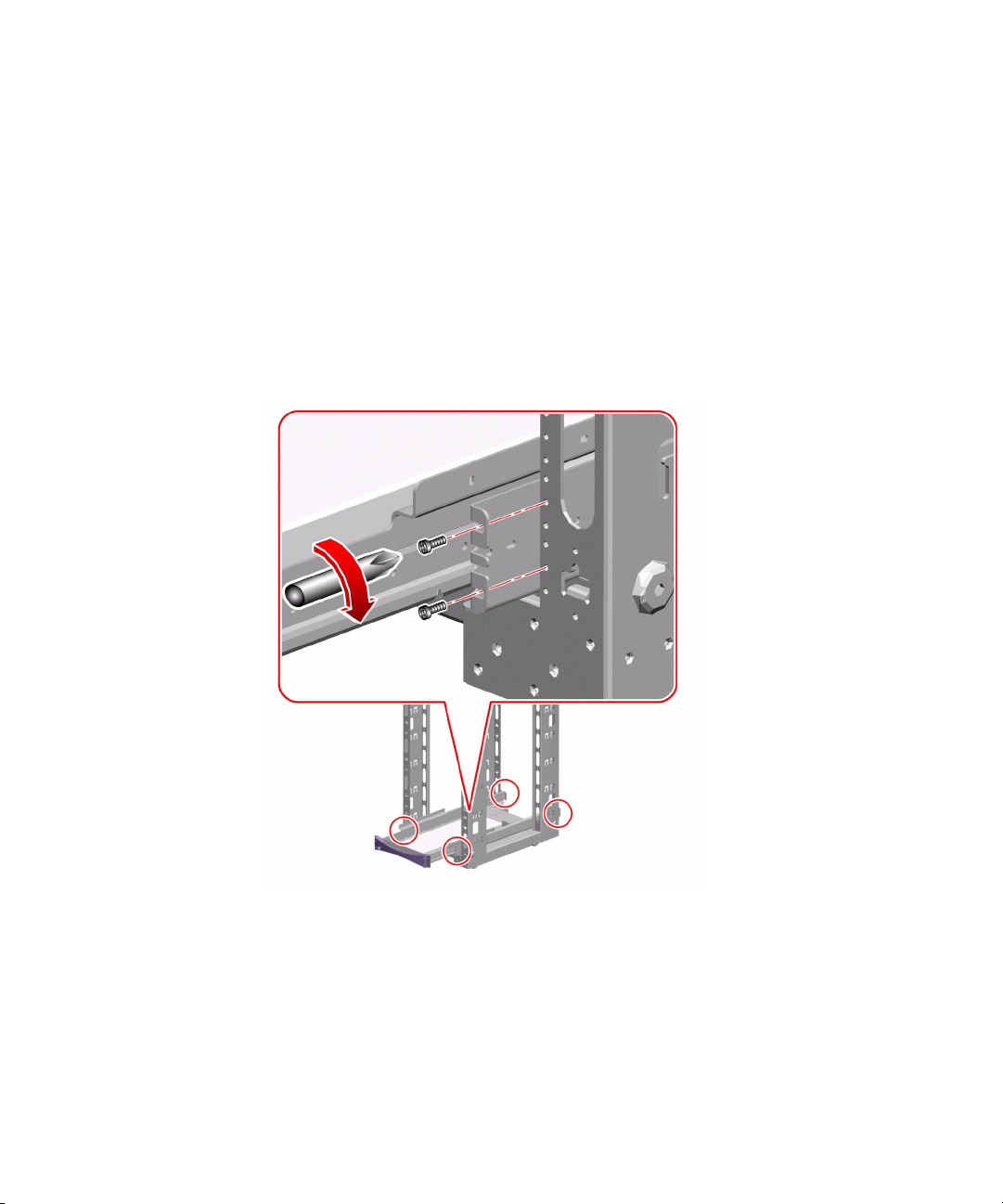
b. Attach the front brackets to the front rails of the cabinet using four 10-32
screws.
Align the lower hole of each front bracket with the front rail holes you marked in
“Determine the Vertical Position of the Server in the Cabinet” on page 19.
Secure the front brackets using one 10-32 screw in the lower hole of each bracket.
Finger-tighten the screws.
Align the upper hole of each front bracket with the corresponding hole in the
cabinet rail. Secure the brackets to the rail using one 10-32 screw in each upper
hole. Finger-tighten the screws.
Do not tighten the screws completely until all the screws are in place and the tray
assembly is level.
Chapter 2 Installing the Server Into the Cabinet 21
Page 30

2. Attach the rear brackets to the rear rails of the cabinet using four 10-32 screws.
Align the lower hole of each rear bracket with the rail hole you marked in
“Determine the Vertical Position of the Server in the Cabinet” on page 19.
Secure the brackets using one 10-32 screw in each lower hole. Finger-tighten the
screws.
Align the upper hole of each rear bracket with the coinciding hole in the cabinet rail.
Secure the bracket to the rail using one 10-32 screw in each upper hole.
Finger-tighten the screws.
Do not tighten the screws completely until all the screws are in place and the tray
assembly is level.
3. Make sure the tray assembly is level.
Use a level to ensure the tray assembly is level front-to-back and left-to-right.
Adjust as necessary.
4. Once the tray assembly is level, completely tighten all of the bracket screws.
Tighten the eight 10-32 screws that secure the front and rear brackets to the vertical
cabinet rails.
5. Slide the tray assembly in and out of the cabinet to be sure the slides operate
smoothly.
22 Sun Fire 880 Server Rackmounting Guide • August 2001
Page 31
Installing the Server Into the Tray Assembly
1. Be sure the cabinet is stabilized so that the cabinet cannot move or tip forward
when the tray is extended and the server is placed on the tray.
If there are feet beneath the cabinet to prevent it from rolling, be sure the feet are
fully extended downward to the floor.
Stabilize the cabinet using the stabilizing mechanisms provided with the cabinet.
See the instructions provided with the cabinet.
Caution – Before you slide the tray out, be sure the cabinet is stabilized so that it
!
cannot move or tip forward. See the cabinet documentation for information about
stabilizing the cabinet.
Some cabinets may be equipped with
stabilizers or bolt-down mechanisms.
See the cabinet documentation for
stabilizing instructions.
Stabilizers
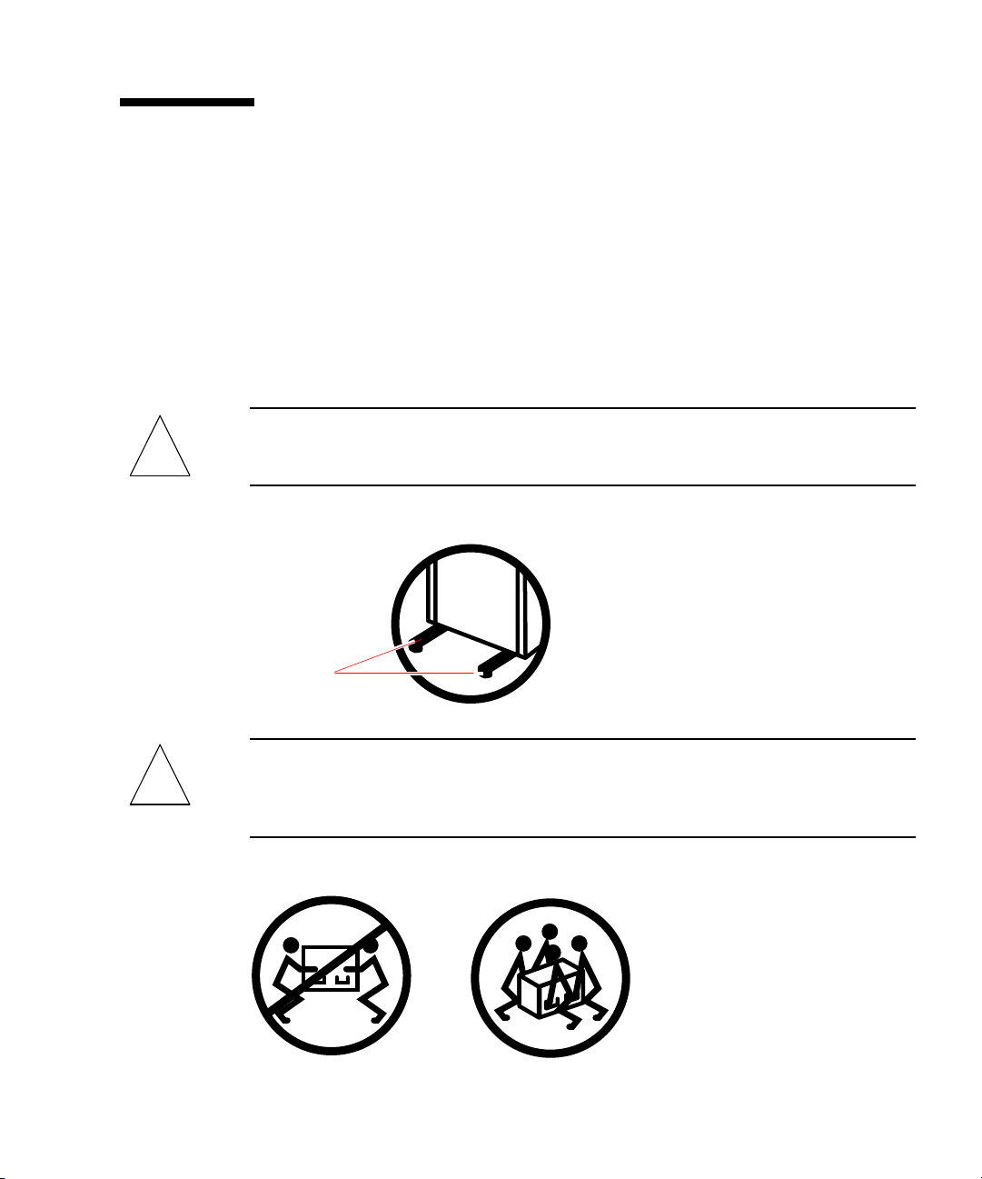
Caution – Do not attempt to lift the server until you remove all CPU/Memory
!
boards, all power supplies, all CPU fan trays, and all I/O fan trays. Once these
components are removed, four persons are required to lift the server. See “Preparing
the Server” on page 8 for information about removing these components.
Chapter 2 Installing the Server Into the Cabinet 23
Page 32
2. Extend the tray all the way forward.
Standing in front of the cabinet, grasp the tray handle and pull the tray toward you
until it stops.
Caution – Do not place your fingers on the tray or under the server while you are
!
lifting the server and positioning it on the tray.
3. Place the server on the tray.
a. Lift the server (two persons on each side of the server) by the lifting handles
that you installed in “Preparing the Server” on page 8.
b. Position the server on the tray so that the front of the server is at the front of
the tray and the back of the server is at the back of the tray.
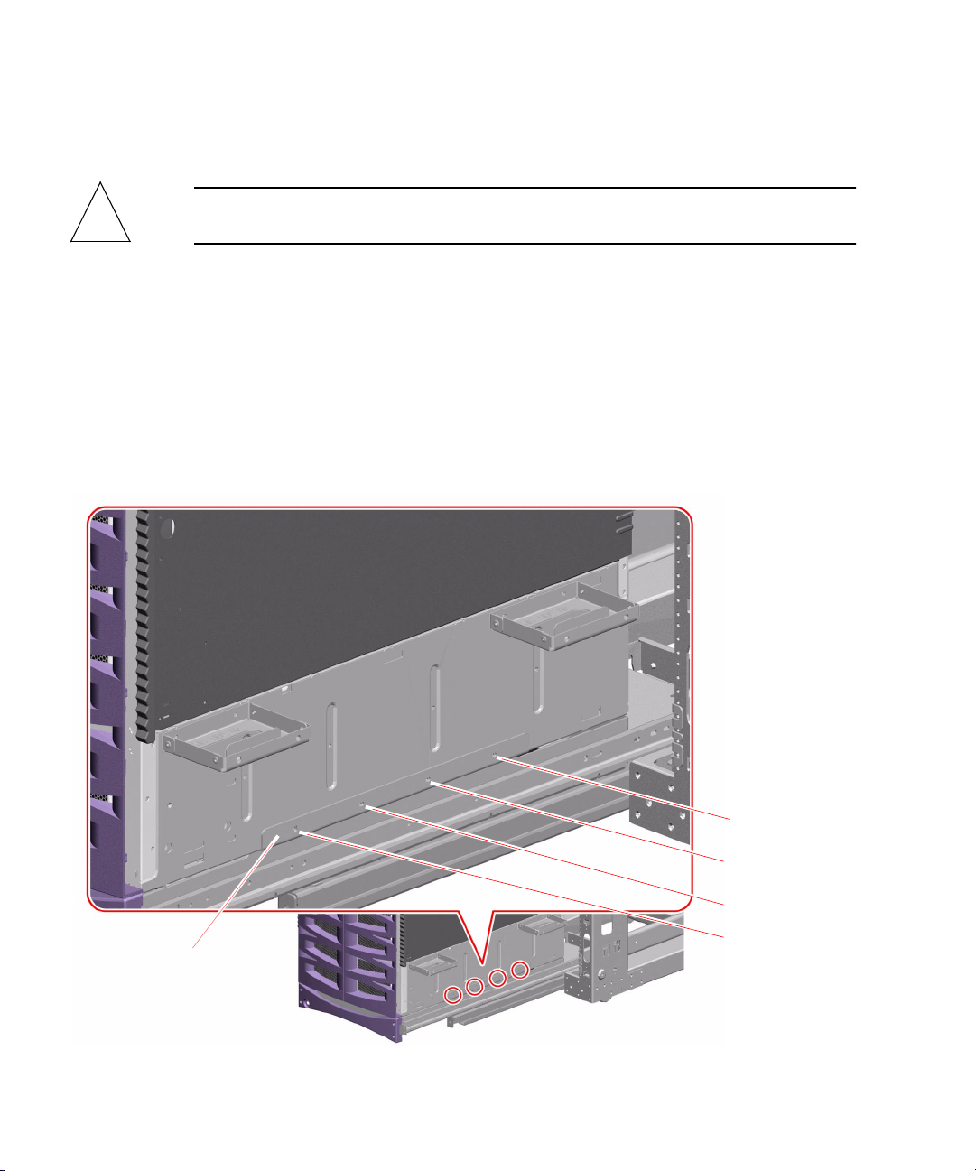
4. Adjust the server on the tray until the four holes on each side of the server align
with the four holes in the tray assembly.
Tr ay
24 Sun Fire 880 Server Rackmounting Guide • August 2001
Align the four
screw holes on
the tray with
the four screw
holes on the
server.
Page 33
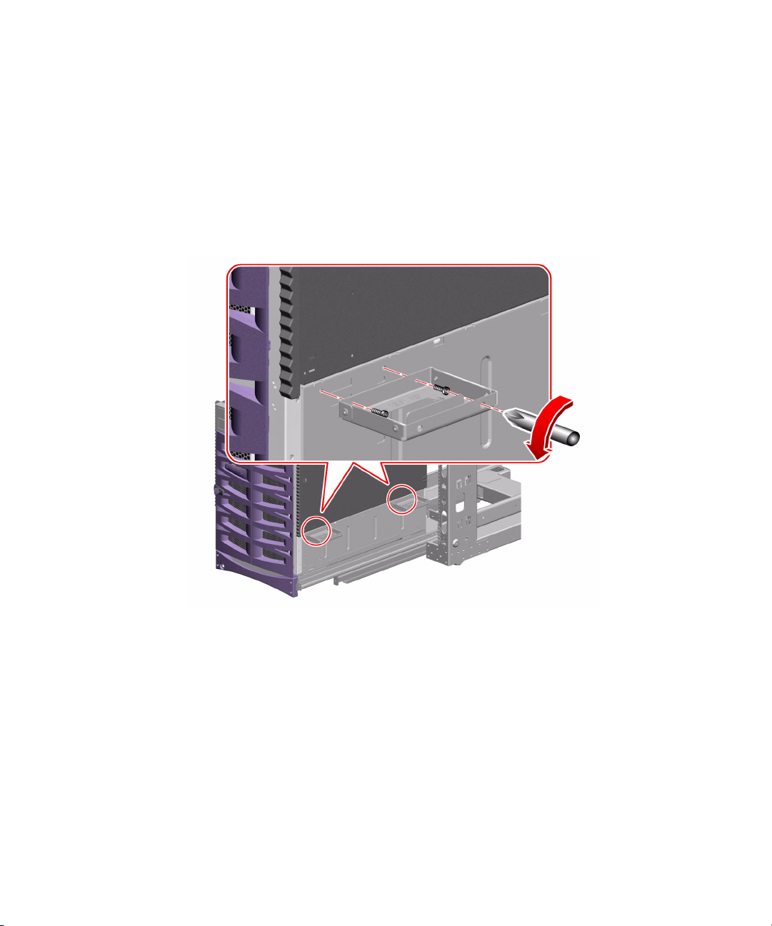
5. Remove the four lifting handles from the sides of the server.
a. Insert the screwdriver through one of the access holes on the outside of the
handle.
Using the access hole makes it easier to reach the opposite screw hole on the
inside of the handle to remove the screw. See the following figure.
b. Remove the two M4 screws that attach each handle to the server.
c. Save the eight M4 screws you remove. You will need to use the screws in step 7.
6. Secure the handles to the rack for safekeeping.
You must reattach the handles if you need to remove the server from the cabinet.
Chapter 2 Installing the Server Into the Cabinet 25
Page 34
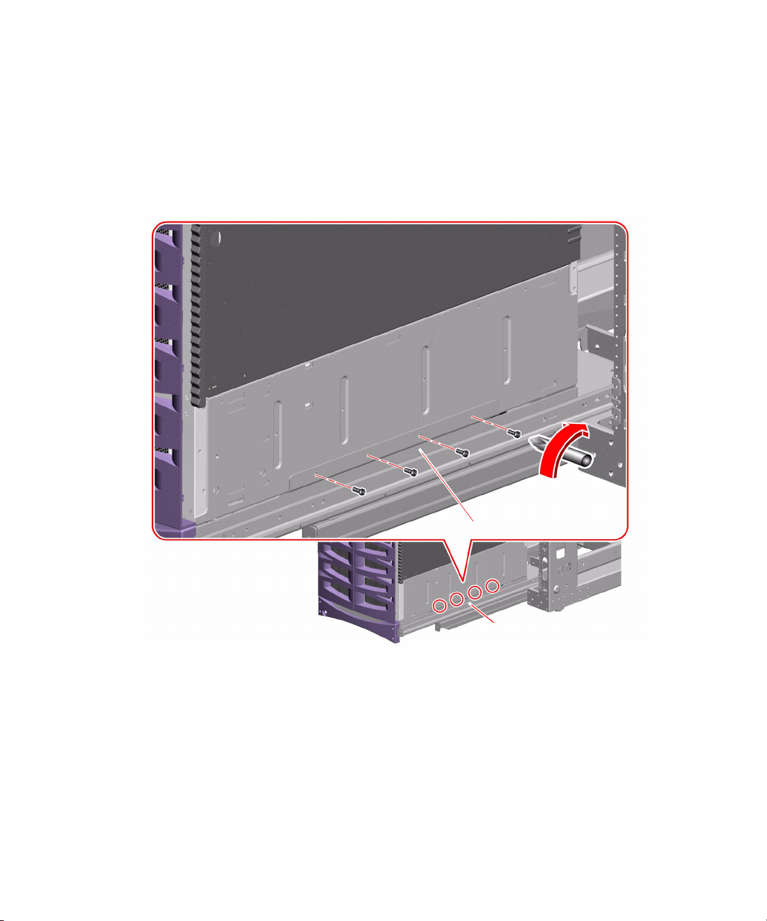
7. Secure the server to the tray assembly using the eight M4 screws you removed in
step 5.
Use four M4 screws on each side of the server as shown in the following figure.
Do not tighten the screws until all screws are in place and you check the placement
of the server.
26 Sun Fire 880 Server Rackmounting Guide • August 2001
Tr ay
Tr ay
Page 35
8. Check that the server is level and centered on the tray.
Use a level and adjust the server position if necessary.
9. Tighten the eight M4 screws that secure the server to the tray assembly.
Restoring the Server
1. Install the CPU/Memory boards and fan trays that you removed before you
installed the server into the cabinet.
See the Sun Fire 880 Server Service Manual for instructions to install components.
2. If you removed the server’s side doors, replace them.
Caution – Avoid keeping the server ’s doors open for extended periods while the
!
system is operating. Server doors must be closed to prevent automatic thermal
shutdown.
3. Close both of the server’s side doors securely.
4. Slide the tray assembly into the cabinet.
5. Install the power supplies that you removed before you installed the server into
the cabinet.
See the Sun Fire 880 Server Service Manual for installation instructions.
Chapter 2 Installing the Server Into the Cabinet 27
Page 36
Securing the Server in the Cabinet
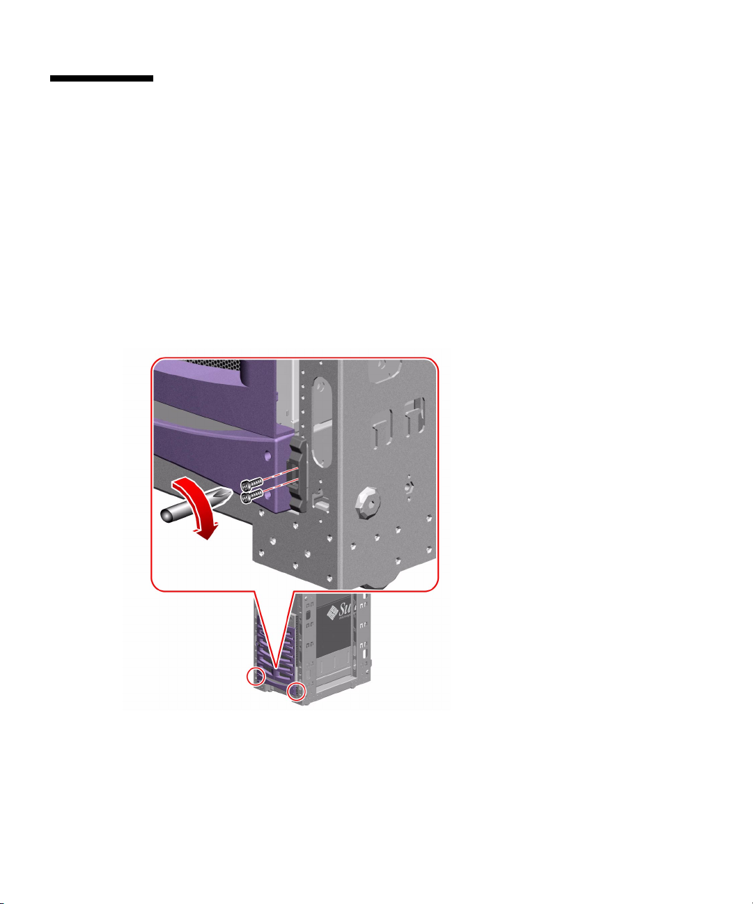
To secure the tray assembly and server in the cabinet, attach the tray handle to the
front rails of the cabinet.
1. Attach the tray handle to the front rails of the cabinet.
Use one or two 10-32 screws to attach the tray handle to the front rails.
If each of the two screw holes on each side of the handle aligns with a rail hole, use
two 10-32 screws to attach each side of the tray handle to each front rail as shown in
the following figure.
If only one screw hole on each side of the handle aligns with a rail hole, use one
10-32 screw to attach each side of the tray handle to each front rail.
2. Locate the Sun Fire 880 server key.
28 Sun Fire 880 Server Rackmounting Guide • August 2001
Page 37
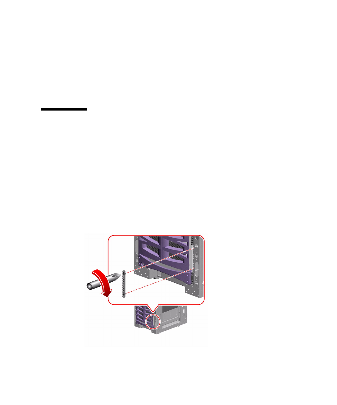
3. Lock the system in the cabinet.
Insert the Sun Fire 880 server key into the keylock on the tray handle and turn the
key 90 degrees counterclockwise.
Locking the tray handle extends the security plates so that they cover the screw
heads on each side of the tray handle. The security plates prevent removal of the
screws that secure the tray and the server to the cabinet.
4. Remove and safeguard the key.
Installing Trim Strips
The lower decorative panels (trim strips) were removed when you removed the
lower side panels. To restore the trim strips:
1. Locate the two trim strips provided in the rackmounting kit.
2. Attach one trim strip to the right front cabinet rail and one trim strip to the left
front cabinet rail.
Using the two captive screws, attach each trim strip as shown in the following
figure.
If only one screw on each trim strip aligns with a rail hole, use one screw to attach
each trim strip to each front rail.
Chapter 2 Installing the Server Into the Cabinet 29
Page 38
Restoring the Cabinet
1. Replace the front and back doors of the cabinet, if applicable.
See the instructions provided with the cabinet.
2. If you removed the side panels from the cabinet, do not replace them until you
connect and route the server cables.
Caution – To prevent the cabinet from tipping forward, do not attempt to roll or
!
move the cabinet after installing the server in the cabinet.
Managing Cables
You will need to develop a cable management scheme that is customized for your
installation. The Sun Fire 880 server rackmounting kit provides several tools that
may aid you in managing the server power cords and cables:
■ Cable management bracket (with integrated releasable tie wraps) that attaches to
the rear of the server. See “Attach the Server Cable Management Bracket” on
page 16.
■ Cable management bracket (with separate releasable tie wraps) that attaches to
the rear of the cabinet. See “Attach the Cable Management Bracket to the Cabinet”
on page 31.
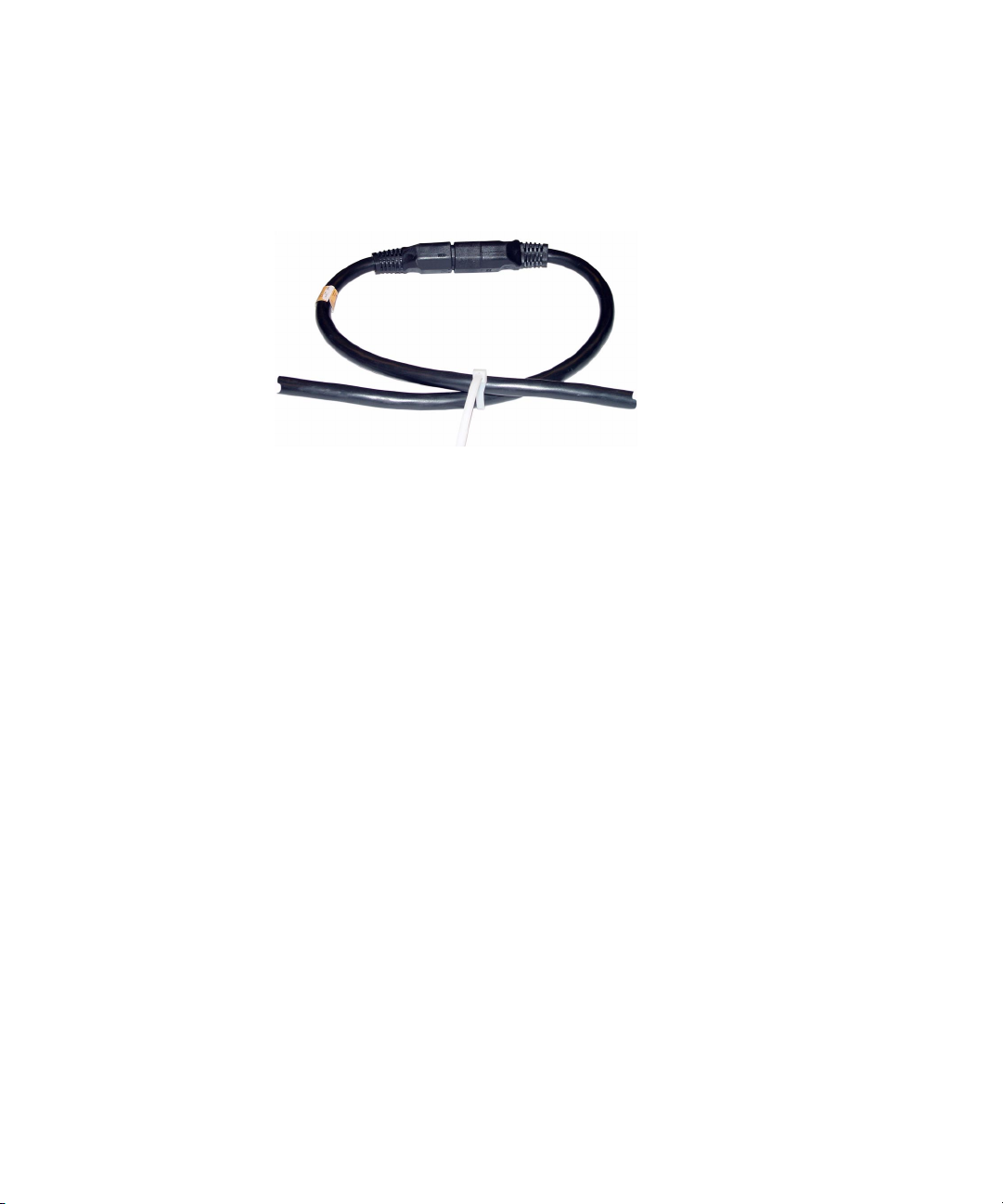
■ Three universal power jumper cords that enable you to provide additional slack
in the server power cords. See the following general guidelines for more
information.
In addition, some cabinets have cable management features or optional cable
management accessories.
The following are general guidelines for routing and managing the server cables:
■ Allow enough slack in the server power cords and cables so that the tray
assembly can be fully extended from the front of the cabinet for service access. If
the server power cords are too short for your particular installation, three
universal jumper cords, provided with the rackmounting kit, allow you to gain
the additional slack needed. One end of a jumper cord plugs into a Sun Fire 880
server power supply; the other end of the jumper cord plugs into a Sun Fire 880
server power cord. The server power cord then plugs into an AC power source.
30 Sun Fire 880 Server Rackmounting Guide • August 2001
Page 39
■ To prevent bending or pinching of the cables when the tray assembly is fully
extended, be sure that all cables are kept clear of the slides and other obstructions.
■ When connecting the power jumper cords to the server’s power cords, use tie
wraps to secure each connection, as shown below.
Attach the Cable Management Bracket to the Cabinet
The cable management bracket that attaches to the rear of the cabinet may help to
provide strain relief for the power cord and other server cables. Releasable tie wraps
provided with the rackmounting kit can be used to secure the cables. See “Managing
Cables” on page 30 for general cable management guidelines.
To attach the cable management bracket to the rear of the cabinet, complete the
following steps:
1. Locate the cable management bracket for the cabinet.
This bracket was provided with the rackmounting kit.
Chapter 2 Installing the Server Into the Cabinet 31
Page 40
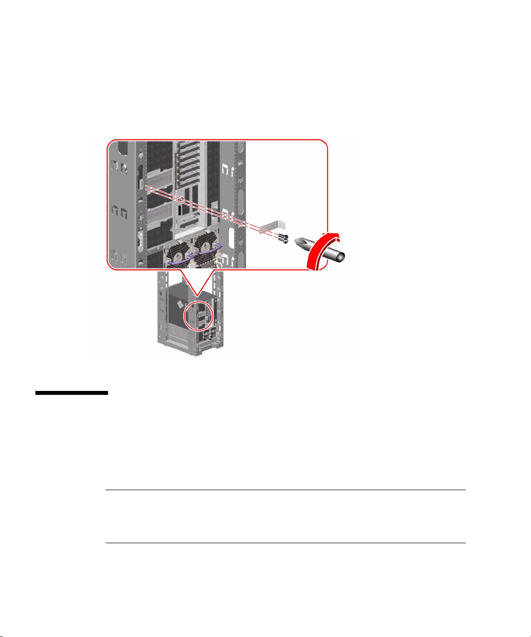
2. Attach the bracket to one of the rear rails of the cabinet as shown in the following
figure.
Use two 10-32 screws to attach the bracket to the cabinet rail.
You can attach the bracket to either the right or left rear rail of the cabinet and at any
location on the rail that suits your cable management scheme.
What Next
Connect the server power cords, network cables, and I/O interface cables to the
server and route the cables, allowing enough slack for service access. See “How to
Install the Sun Fire 880 Server” in the Sun Fire 880 Server Owner’s Guide.
Note – A grounding screw is located just above the server’s center power supply. Be
sure to ground the server to the cabinet using an appropriate grounding strap.
Proper grounding prevents ground loops between systems and peripherals and
helps guard against possible data loss.
32 Sun Fire 880 Server Rackmounting Guide • August 2001
Page 41

APPENDIX
A
Cabinet Requirements
The server can be installed into a 19-inch (48.3-cm) wide EIA-compliant cabinet that
meets the requirements listed in the table below. You need one Sun Fire 880 server
rackmounting kit for each Sun Fire 880 server that you will install into a cabinet.
Cabinet Feature Requirement
Load Bearing Capacity The cabinet must firmly support the weight of a Sun Fire 880
server and the mounting hardware (up to 350 lb, 158.8 kg,
depending on the server configuration), plus the weight of any
other installed devices.
Anti-Tilt Protection The cabinet must be bolted securely to the floor or equipped with
a sturdy and extendable anti-tip leg. You must prevent the cabinet
from moving or tilting forward when one or more systems or
devices are fully extended from the front of the cabinet.
Vertical Space
Requirements
Minimum Service
Access
Each server requires 17 rack units (29.75 inches, 75.6 cm) of
vertical space for cabinet installation.
An area not less than 3 feet (91 cm) deep must be
available in back of the cabinet for server installation and
service access.
An area not less than 4 feet (122 cm) deep must be
available in front of the cabinet for server installation and
server access.
An area not less than 3 feet (91 cm) wide must be
available on each side of the server when the server is
fully extended on the tray assembly.
When fully extended on the tray assembly, the server will
protrude 32.9 inches (83.6 cm) forward of the cabinet’s front
vertical mounting rails.
33
Page 42

Cabinet Feature Requirement
Airflow For proper ventilation of the server, the front and rear doors must
comply with the following minimum open area requirements.
• 60 percent of the area of the front door that is directly in front
of the server must be open.
• 63 percent of the area of the rear door that is directly behind the
server must be open.
If the doors of the cabinet do not meet the open area
requirements, remove the door or doors that do not comply.
Vertical Mounting Rail
Requirements
The cabinet must have two pairs of vertical mounting rails (one
pair in front, one in back) that conform to the EIA (RETMA)
standard for mounting hole spacing.
Front-to-rear rail spacing must be at least 32 inches (81.3 cm) and
not more than 36 inches (91.4 cm) from the outside face of the
front rail to the outside face of the rear rail.
Front and rear vertical rail mounting faces must be parallel to
each other and to the front plane of the cabinet.
Doors and Panels Depending on your cabinet, you may need to remove the front
and rear door and side panels to access the server or to provide
proper ventilation. See Minimum Service Access requirements
and Airflow requirements given previously in this appendix.
See the instructions provided with the cabinet for information
about removing the front and rear doors and side panels from the
cabinet.
EMI Requirements Electromagnetic interference (EMI) shielding requirements are
met by the system chassis and metal side doors, which must
remain in place when the unit is installed in the cabinet.
Fire Containment The cabinet must meet Underwriters Laboratories, Inc. and TUV
Rheinland of N.A. requirements for fire containment.
34 Sun Fire 880 Server Rackmounting Guide • August 2001
 Loading...