

Sun Microsystems Sun Fire 4810, Sun Fire 4800, Sun Fire 3800 Mounting Manual [en, fr, es, de]
Page 1

Sun Fire™4810/4800/3800 Systems
Cabinet Mounting Guide
Sun Microsystems, Inc.
4150 Network Circle
Santa Clara, CA 95054 U.S.A.
650-960-1300
Part No. 806-6781-12
January 2002, Revision A
Send comments about this document to: [email protected]
Page 2

Copyright 2002Sun Microsystems,Inc., 4150Network Circle •Santa Clara,CA 95054USA. Allrights reserved.
This productor documentis protected bycopyright anddistributed underlicenses restrictingits use,copying, distribution,and decompilation.
No partof thisproduct ordocument maybe reproduced inany formby anymeans withoutprior writtenauthorization ofSun andits licensors,
if any.Third-party software, includingfont technology,is copyrightedand licensedfrom Sunsuppliers.
Parts ofthe productmay bederived from BerkeleyBSD systems,licensed fromthe Universityof California.UNIX isa registered trademarkin
the U.S.and othercountries, exclusivelylicensed throughX/Open Company, Ltd.
Sun, SunMicrosystems, theSun logo,AnswerBook2, docs.sun.com,Sun Fire, andSolaris aretrademarks, registered trademarks,or service
marks ofSun Microsystems,Inc. inthe U.S.and othercountries. AllSPARC trademarks areused underlicense andare trademarksor registered
trademarks ofSPARC International,Inc. inthe U.S.and othercountries. Productsbearing SPARC trademarks are basedupon anarchitecture
developed bySun Microsystems,Inc.
The OPENLOOK andSun™ GraphicalUser Interfacewas developedby SunMicrosystems, Inc.for itsusers andlicensees. Sunacknowledges
the pioneeringefforts ofXerox in researchingand developingthe conceptof visualor graphicaluser interfacesfor thecomputer industry. Sun
holds anon-exclusive licensefrom Xerox tothe XeroxGraphical UserInterface, whichlicense alsocovers Sun’slicensees whoimplement OPEN
LOOK GUIsand otherwisecomply withSun’s writtenlicense agreements.
Federal Acquisitions:Commercial Software—Government UsersSubject toStandard LicenseTerms and Conditions.
DOCUMENTATION IS PROVIDED “AS IS” AND ALLEXPRESS OR IMPLIEDCONDITIONS, REPRESENTATIONS AND WARRANTIES,
INCLUDING ANY IMPLIED WARRANTY OF MERCHANTABILITY, FITNESS FOR A PARTICULAR PURPOSE OR NONINFRINGEMENT, ARE DISCLAIMED, EXCEPT TO THE EXTENT THAT SUCH DISCLAIMERS ARE HELD TO BE LEGALLY INVALID.
Copyright 2002Sun Microsystems,Inc., 4150Network Circle •Santa Clara,CA 95054Etats-Unis. Tous droitsréservés.
Ce produitou documentest protégé parun copyrightet distribuéavec deslicences quien restreignent l’utilisation,la copie,la distribution,et la
décompilation. Aucunepartie dece produitou documentne peutêtre reproduite sousaucune forme,par quelquemoyen quece soit,sans
l’autorisation préalableet écritede Sunet deses bailleursde licence,s’il yen a.Le logicieldétenu pardes tiers,et quicomprend latechnologie
relative auxpolices decaractères, est protégépar uncopyright etlicencié pardes fournisseursde Sun.
Des partiesde ceproduit pourront êtredérivées dessystèmes BerkeleyBSD licenciéspar l’Universitéde Californie.UNIX estune marque
déposée auxEtats-Unis etdans d’autrespays etlicenciée exclusivementpar X/OpenCompany, Ltd.
Sun, SunMicrosystems, lelogo Sun,AnswerBook2, docs.sun.com,Sun Fire, etSolaris sontdes marquesde fabriqueou desmarques déposées,
ou marquesde service,de SunMicrosystems, Inc. aux Etats-Unis et dans d’autrespays. Toutes les marques SPARC sont utilisées sous licence et
sont desmarques defabrique oudes marques déposéesde SPARC International, Inc. aux Etats-Unis et dans d’autrespays. Lesproduits portant
les marquesSPARC sont basés sur une architecture développéepar SunMicrosystems, Inc.
L’interfaced’utilisation graphiqueOPEN LOOKet Sun™a étédéveloppée parSun Microsystems, Inc.pour sesutilisateurs etlicenciés. Sun
reconnaît lesefforts de pionniers de Xeroxpour larecherche et le développement du concept des interfaces d’utilisation visuelle ou graphique
pour l’industriede l’informatique.Sun détientune licencenon exclusivede Xeroxsur l’interfaced’utilisation graphiqueXerox, cette licence
couvrant égalementles licenciésde Sunqui mettenten placel’interface d’utilisationgraphique OPENLOOK etqui enoutre seconforment aux
licences écritesde Sun.
CETTE PUBLICATION EST FOURNIE “EN L’ETAT” ET AUCUNE GARANTIE, EXPRESSE OU IMPLICITE, N’EST ACCORDEE, Y
COMPRIS DES GARANTIES CONCERNANT LA VALEUR MARCHANDE, L’APTITUDE DE LA PUBLICATION A REPONDRE A UNE
UTILISATION PARTICULIERE, OU LE FAIT QU’ELLE NE SOIT PAS CONTREFAISANTE DE PRODUIT DE TIERS. CE DENI DE
GARANTIE NE S’APPLIQUERAIT PAS, DANS LA MESURE OU IL SERAIT TENU JURIDIQUEMENT NUL ET NON AVENU.
Page 3

Contents
Preface ix
1. Installing the Sun Fire 4810 System into a Sun Fire Cabinet 1-1
1.1 Tools 1-1
1.2 Mounting the Brackets 1-2
1.3 Mounting the Sun Fire 4810 System 1-4
1.4 Connecting Power Cables to the Sun Fire 4810 System 1-6
1.5 Attaching Cabinet Front Panels 1-8
1.6 Attaching Cabinet Guards 1-10
1.7 Connecting the System Controller to the FrameManager 1-11
2. Installing the Sun Fire 4800 System into a Sun Fire Cabinet 2-1
2.1 Tools 2-1
2.2 Mounting the Rails 2-2
2.3 Removing the Bumper 2-4
2.4 Removing the Side Panels 2-5
2.5 Removing the Casters 2-6
2.6 Mounting the Sun Fire 4800 System 2-6
2.7 Connecting Power Cables to the Sun Fire 4800 System 2-8
2.8 Attaching Cabinet Front Panels 2-10
2.9 Attaching Cabinet Guards 2-12
iii
Page 4

2.10 Connecting the System Controller to the FrameManager 2-13
3. Installing the Sun Fire 3800 System into a Sun Fire Cabinet 3-1
3.1 Tools 3-1
3.2 Mounting the Rails 3-2
3.3 Installing the Cable Raceways 3-4
3.4 Mounting the Sun Fire 3800 System 3-6
3.5 Installing the Sun Fire Cabinet Extension Brackets 3-8
3.6 Connecting Power Cables to the Sun Fire 3800 System 3-10
3.7 Attaching Cabinet Front Panels 3-12
3.8 Attaching Cabinet Guards 3-14
3.9 Connecting the System Controller to the FrameManager 3-15
A. Regulatory Compliance Statements A-1
B. Compliance Statements 1
iv Sun Fire 4810/4800/3800 Systems Cabinet Mounting Guide • January 2002
Page 5

Figures
FIGURE 1-1 Mounting System Brackets to the Sun Fire 4810 System 1-2
FIGURE 1-2 Lettered Holes on the Cabinet Bracket 1-3
FIGURE 1-3 Adding Cabinet Brackets and Rails to the Sun Fire Cabinet 1-4
FIGURE 1-4 Mounting the Sun Fire 4810 System into a Sun Fire Cabinet 1-5
FIGURE 1-5 Power Switch Locations on the Cabinet Mounted Sun Fire 4810 System 1-7
FIGURE 1-6 Cabinet Front Panel Locations 1-9
FIGURE 1-7 Cabinet Guard Installation 1-10
FIGURE 2-1 Rail Installation in Sun Fire Cabinet 2-3
FIGURE 2-2 Bumper location on Sun Fire 4800 system 2-4
FIGURE 2-3 Removing Side Panels from the Sun Fire 4800 system 2-5
FIGURE 2-4 Mounting the Sun Fire 4800 System into the Sun Fire Cabinet 2-7
FIGURE 2-5 Power Switch Locations on the Cabinet Mounted Sun Fire 4800 System 2-9
FIGURE 2-6 Cabinet Front Panel Locations 2-11
FIGURE 2-7 Cabinet Guard Installation 2-12
FIGURE 3-1 Rail Hole Identification 3-2
FIGURE 3-2 Mounting Bracket Installation in Sun Fire Cabinet 3-3
FIGURE 3-3 Cable Raceway Installation 3-5
FIGURE 3-4 Securing the Sun Fire 3800 System in the Sun Fire Cabinet 3-7
FIGURE 3-5 Installing Sun Fire Cabinet Extension Brackets 3-9
v
Page 6

FIGURE 3-6 Power Switch Locations on the Cabinet Mounted Sun Fire 3800 System 3-11
FIGURE 3-7 Cabinet Front Panel Locations 3-13
FIGURE 3-8 Cabinet Guard Installation 3-14
vi Sun Fire 4810/4800/3800 Systems Cabinet Mounting Guide • January 2002
Page 7

Tables
TABLE 1-1 Sun Fire 4810 Cabinet Guard Locations 1-10
TABLE 2-1 Sun Fire 4800 Cabinet Guard Locations 2-12
TABLE 3-1 Sun Fire 3800 System Rackmounting Order 3-2
TABLE 3-2 Sun Fire 3800 System Cable Raceway Locations 3-4
TABLE 3-3 Sun Fire 3800 Cabinet Guard Locations 3-14
vii
Page 8

viii Sun Fire 4810/4800/3800 Systems Cabinet Mounting Guide • January 2002
Page 9

Preface
The Sun Fire™ 4810/4800/3800 Systems Cabinet Mounting Guide provides installation
instructions for mounting the Sun Fire 4810, Sun Fire 4800, and Sun Fire 3800
systems into a Sun Fire cabinet. These instructions are not for mounting these
systems in industry standard 19-inch racks.
These instructions are for an experienced systems or field engineer with networking
knowledge.
Typographic Conventions
Typeface or
Symbol Meaning Examples
AaBbCc123 The names of commands, files,
and directories; on-screen
computer output.
AaBbCc123
AaBbCc123 Book titles, new words or
What you type, when
contrasted with on-screen
computer output.
terms, words to be emphasized.
Command-line variable;
replace with a real name or
value.
Edit your .login file.
Use ls -a to list all files.
% su
Password:
Read Chapter 6 in the User’s Guide.
These are called class options.
Yo u must be superuser to do this.
To delete a file, type rm filename.
ix
Page 10

Related Documentation
Application Title
Sun Fire 4810/4800/3800 System Getting Started 805-7374
Sun Fire 6800/4810/4800/3800 Systems Overview Manual 805-7362
Hardware Sun Fire 4810/4800/3800 System Installation Guide 805-7375
Sun Fire Cabinet Installation and Reference Manual 806-2942
Sun Fire 6800/4810/4800/3800 Systems Service Manual 805-7363
Software Sun Fire 6800/4810/4800/3800 System Controller Command Reference Manual 805-7372
Sun Fire 6800/4810/4800/3800 Systems Platform Administration Manual 805-7373
Part
Number
Accessing Sun Documentation Online
A broad selection of Sun system documentation is located at:
http://www.sun.com/products-n-solutions/hardware/docs
A complete set of Solaris documentation and many other titles are located at:
http://docs.sun.com
Ordering Sun Documentation
Fatbrain.com, an Internet professional bookstore, stocks select product
documentation from Sun Microsystems, Inc.
For a list of documents and how to order them, visit the Sun Documentation Center
on Fatbrain.com at:
http://www.fatbrain.com/documentation/sun
x Sun Fire 4810/4800/3800 Systems Cabinet Mounting Guide • January 2002
Page 11

Sun Welcomes Your Comments
Sun is interested in improving its documentation and welcomes your comments and
suggestions. You can email your comments to Sun at:
Please include the part number (806-6781-12) of your document in the subject line of
your email.
Cautions and Notes
Caution – This equipment contains lethal voltage. Accidental contact with
centerplane, card cage, and drive areas can result in serious injury or death.
Caution – Improper handling by unqualified personnel can cause serious damage
to this equipment. Unqualified personnel who tamper with this equipment may be
held liable for any resultant damage to the equipment.
Individuals who remove any outer panels or open covers to access this equipment
must observe all safety precautions and ensure compliance with skill level
requirements, certification, and all applicable local and national laws.
Procedures contained in this document must be performed by qualified servicetrained maintenance providers.
Note – Before you begin, carefully read each of the procedures in this manual. If
you have not performed similar operations on comparable equipment, do not
attempt to perform these procedures.
xi
Page 12

xii Sun Fire 4810/4800/3800 Systems Cabinet Mounting Guide • January 2002
Page 13
CHAPTER
1
Installing the Sun Fire 4810System
into a Sun Fire Cabinet
The Sun Fire 4810 system is designed to be mounted in a rack. All the hardware
necessary to mount the system in a Sun Fire cabinet enclosure is included in the
shipping carton.
■ Tools—page 1-1
■ Mounting the Brackets—page 1-2
■ Mounting the Sun Fire 4810 System—page 1-4
■ Connecting Power Cables to the Sun Fire 4810 System—page 1-6
■ Attaching Cabinet Front Panels—page 1-8
■ Attaching Cabinet Guards—page 1-10
■ Connecting the System Controller to the FrameManager—page 1-11
1.1 Tools
You need the following tools:
■ Screwdriver, Phillips No. 2
Caution – The Sun Fire 4810 system weighs approximately 305 lbs (138.3 kg). To
prevent personal injury, two people are needed to move the system safely into the
cabinet using a computer equipment lift rated for 300 lbs or greater.
1-1
Page 14
1.2 Mounting the Brackets
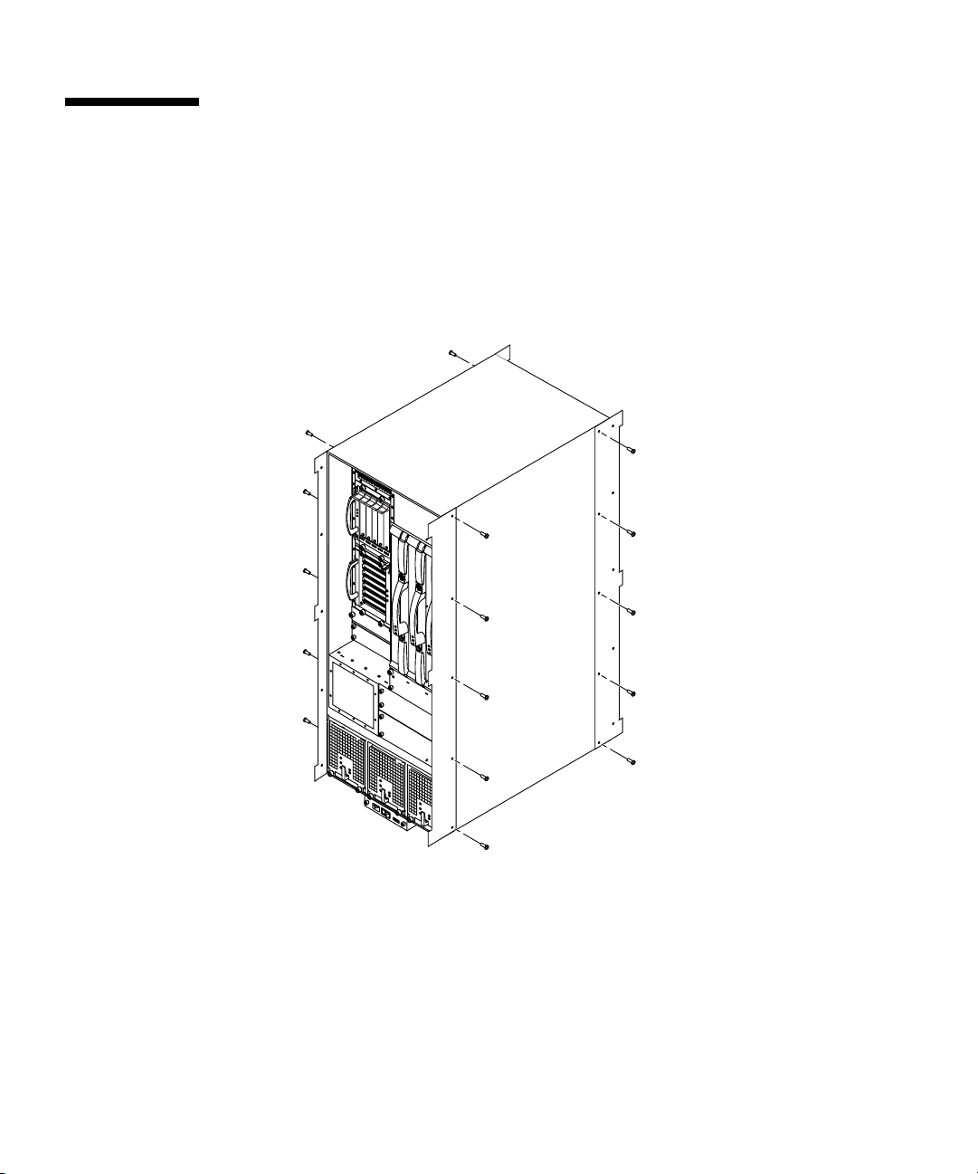
1. Mount the four system brackets vertically onto the Sun Fire 4810 system using five
screws each. Mount the brackets so that they extend beyond the front and rear of
the system.
the system brackets are identical so they can be mounted on either side of the Sun
Fire 4810 system (FIGURE 1-1).
FIGURE 1-1 Mounting System Brackets to the Sun Fire 4810 System
2. Mount the two rails horizontally into the Sun Fire cabinet using four screws per
rail. Screw each hanger hole into cabinet hole #22 and the bottom slots into
cabinet hole #20.
The rails are identical so they can be mounted on either side of the system. They are
shown in FIGURE 1-3.
1-2 Sun Fire 4810/4800/3800 Systems Cabinet Mounting Guide • January 2002
Page 15
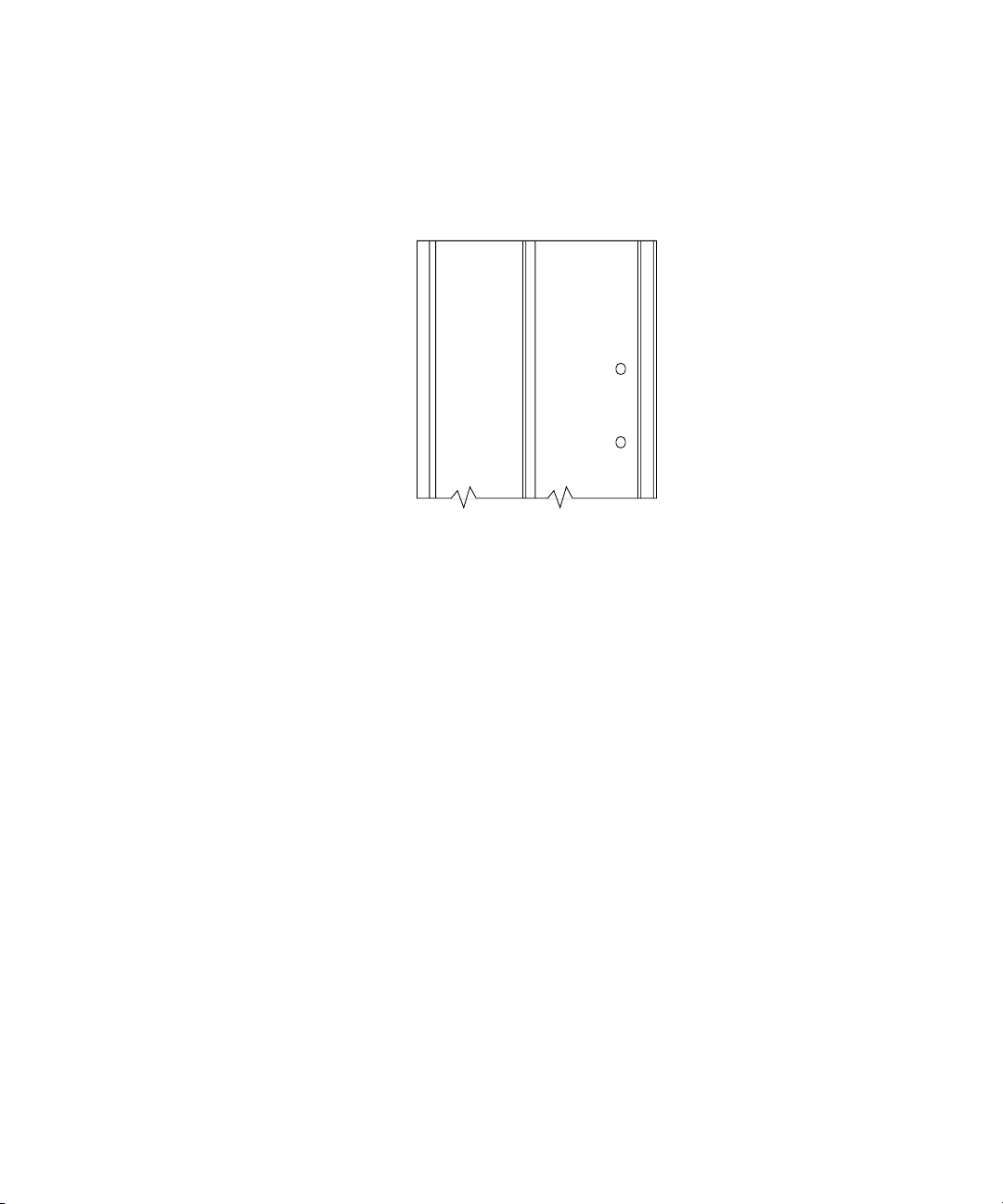
3. Mount the four cabinet brackets vertically into the Sun Fire cabinet using eight
screws for each bracket.
The holes near the ends of the bracket are marked with letters (FIGURE 1-2). Ignore
letters that appear upside-down, they will be correctly oriented on the other end.
A
C
B
D
FIGURE 1-2 Lettered Holes on the Cabinet Bracket
See FIGURE 1-3 for hole designations. Once the lettered holes are aligned, the
remaining holes in the bracket will line up with holes in the cabinet.
Chapter 1 Installing the Sun Fire 4810 System into a Sun Fire Cabinet 1-3
Page 16
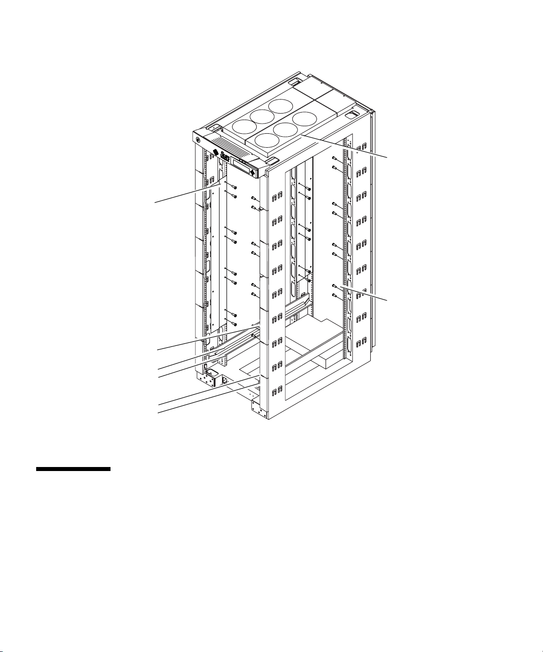
Bracket Hole A
Cabinet Hole #79
Bracket Hole D
Cabinet Hole #40
Cabinet Hole #22
Cabinet Hole #20
Cabinet Hole #22
Cabinet Hole #20
FIGURE 1-3 Adding Cabinet Brackets and Rails to the Sun Fire Cabinet
Bracket Hole B
Cabinet Hole #76
Bracket Hole C
Cabinet Hole #37
1.3 Mounting the Sun Fire 4810 System
1. Locate three power cords close to where the system will be mounted and untie
them from the cabinet so that they will be accessible after the system has been
mounted.
The power cords are pre-installed in the Sun Fire cabinet with one end attached to
the redundant transfer unit (RTU) assemblies.
1-4 Sun Fire 4810/4800/3800 Systems Cabinet Mounting Guide • January 2002
Page 17
Note – Refer to the Rackmount Placement Matrix,athttp://docs.sun.com for
power cord cabling information.
Caution – The Sun Fire 4810 system weighs approximately 305 lbs (138.3 kg). To
prevent personal injury, two people are needed to move the system safely into the
cabinet using a computer equipment lift.
Caution – Make sure the cabinet is stabilized before mounting the system and
storage devices. The anti-tilt bar can be used to prevent the cabinet from tilting.
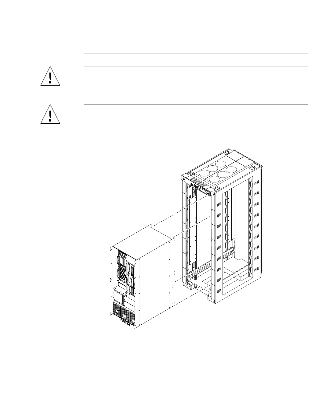
2. Insert the system onto the horizontal rails in the Sun Fire cabinet (FIGURE 1-4).
FIGURE 1-4 Mounting the Sun Fire 4810 System into a Sun Fire Cabinet
3. Secure the system brackets to the cabinet brackets with four screws per bracket.
Chapter 1 Installing the Sun Fire 4810 System into a Sun Fire Cabinet 1-5
Page 18

1.4 Connecting Power Cables to the Sun Fire 4810 System
1. Ensure that each power switch on the Sun Fire cabinet is set to off (FIGURE 1-5).
Note – In a dual RTU configuration, there will be power switches in both the front
and rear of the cabinet. All power switches must be turned off.
2. Ensure that each power switch on the Sun Fire 4810 system is set to off
FIGURE 1-5).
(
3. Connect the power cord to the power cord sockets on system.
Three power cords should have been untied from the cabinet and moved out of the
way during Step 1 of Section 1.3.
4. Loosen the screw above the power cord socket.
This will loosen the bracket that holds the tie wrap.
5. Position the bracket tightly against the power cord.
6. Tighten the tie wrap around the power cord to keep it from being dislodged.
Make sure the tie wrap is tight. Do not trim excess tie wrap.
7. Tighten the screw above the power cord.
8. Repeat Step 3 through Step 7 for each of the three power cords.
Caution – Risk of electric shock. Do NOT turn on AC power to the unit yet.
1-6 Sun Fire 4810/4800/3800 Systems Cabinet Mounting Guide • January 2002
Page 19
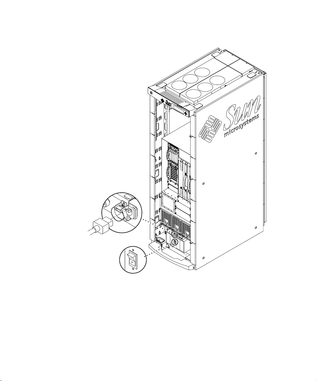
FIGURE 1-5 Power Switch Locations on the Cabinet Mounted Sun Fire 4810 System
Chapter 1 Installing the Sun Fire 4810 System into a Sun Fire Cabinet 1-7
Page 20

1.5 Attaching Cabinet Front Panels
1. Place the first cabinet front panel as close as possible to the top of the system, and
secure the panel to the Sun Fire cabinet by tightening the screws through the left
and right sides of the panel.
2. Secure subsequent panels by tightening the screws through the left and right
front of each panel (
Place each front panel as close to the one below as possible. Use different sized front
panels as necessary to completely fill in the gap above the system. If unable to fill in
the entire gap leave the smallest possible gap at the top of the cabinet.
Note – The large cabinet front panels are not simply cosmetic, they prevent hot air
expelled from the rear of the cabinet from reentering the system from the front.
3. Secure small cosmetic panels on the cabinet adjacent to the system.
FIGURE 1-6).
1-8 Sun Fire 4810/4800/3800 Systems Cabinet Mounting Guide • January 2002
Page 21
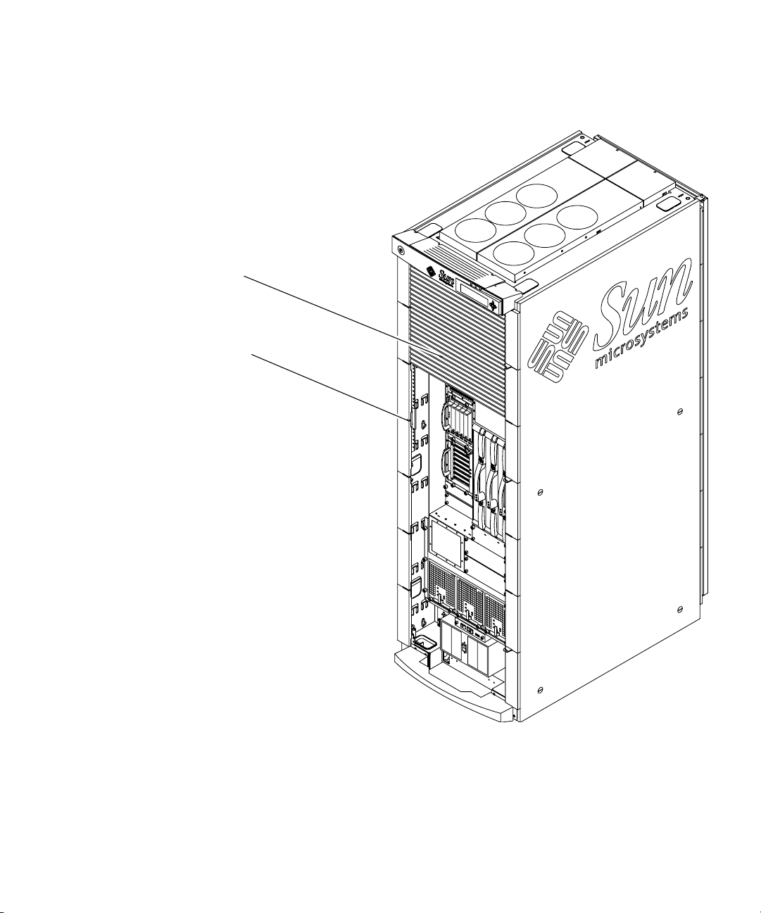
Cabinet Front Panels
Cosmetic Front Panels
FIGURE 1-6 Cabinet Front Panel Locations
Chapter 1 Installing the Sun Fire 4810 System into a Sun Fire Cabinet 1-9
Page 22
1.6 Attaching Cabinet Guards
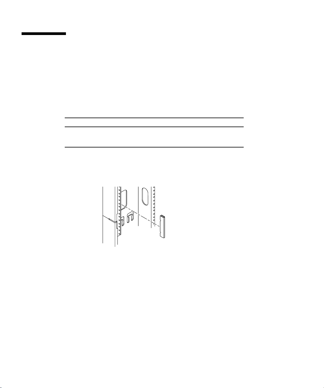
The cabinet guards are designed to protect against injuries that may occur when
boards are removed from the system.
1. Locate the cabinet guard hole locations on the rear of the Sun Fire cabinet using
TABLE 1-1.
TABLE 1-1 Sun Fire 4810 Cabinet Guard Locations
Left Side of Cabinet Right Side of Cabinet
Top notch in rear cabinet hole #74
Top notch in rear cabinet hole #60
2. Align the upper “v” notch on the cabinet guard with the appropriate numbered
hole, and press firmly in the middle of the guard until it stops against the edge of
the cabinet (
FIGURE 1-7).
Top notch in rear cabinet hole #
Top notch in rear cabinet hole #
70
61
FIGURE 1-7 Cabinet Guard Installation
1-10 Sun Fire 4810/4800/3800 Systems Cabinet Mounting Guide • January 2002
Page 23

1.7 Connecting the System Controller to the FrameManager
The Y-serial cable allows the primary System Controller board to be accessed by the
Sun Fire cabinet FrameManager and a serial cable terminal connection
simultaneously.
1. Connect the single end of the Y-serial cable (located in the shipping kit that came
with the system) to the serial port on the primary system controller.
2. Connect the ’A’ end of the Y-serial cable to the serial cable terminal connection (if
any).
3. Connect the ’B’ end of the Y-serial cable to the P2 Cable.
The P2 cable is pre-connected to the FrameManager and secured among the power
cables on the right side of the Sun Fire cabinet.
4. To continue with the installation, refer to the Sun Fire 4810/4800/3800 Systems
Installation Guide Section 2.3.
Chapter 1 Installing the Sun Fire 4810 System into a Sun Fire Cabinet 1-11
Page 24

1-12 Sun Fire 4810/4800/3800 Systems Cabinet Mounting Guide • January 2002
Page 25

CHAPTER
2
Installing the Sun Fire 4800System
into a Sun Fire Cabinet
The Sun Fire 4800 system is designed to be either a standalone unit or mounted in a
rack. All the necessary hardware to mount the system in a Sun Fire cabinet is
included in the shipping carton.
The Sun Fire cabinet can house a single Sun Fire 4800 system.
■ Tools—page 2-1
■ Mounting the Rails—page 2-2
■ Removing the Bumper—page 2-4
■ Removing the Side Panels—page 2-5
■ Removing the Casters—page 2-6
■ Mounting the Sun Fire 4800 System—page 2-6
■ Connecting Power Cables to the Sun Fire 4800 System—page 2-8
■ Attaching Cabinet Front Panels—page 2-10
■ Attaching Cabinet Guards—page 2-12
■ Connecting the System Controller to the FrameManager—page 2-13
2.1 Tools
You need the following tools:
■ Screwdriver, Phillips No. 2
2-1
Page 26

Caution – The Sun Fire 4800 system weighs approximately 289 lbs (131.1 kg). To
prevent personal injury, two people are needed to move the system safely into the
cabinet using a computer equipment lift rated for 300 lbs or greater.
2.2 Mounting the Rails
1. Attach the rails to the Sun Fire cabinet using four screws for each rail (two screws
through the hanger holes and two screws through the slots above the hanger
holes). Cabinet holes numbers are shown in FIGURE 2-1.
The upper rails are identical. Arrows are embossed near the hanger holes. When
installed the arrows should point up, this will force the upper rails into the correct
orientation.
The holes on the bottom rail are identical on the left inside and right inside so that
the rail can be mounted on either side of the cabinet. Use the rear set of hanger holes
on the bottom rail to cause the bottom rail to sit forward in the cabinet.
2-2 Sun Fire 4810/4800/3800 Systems Cabinet Mounting Guide • January 2002
Page 27
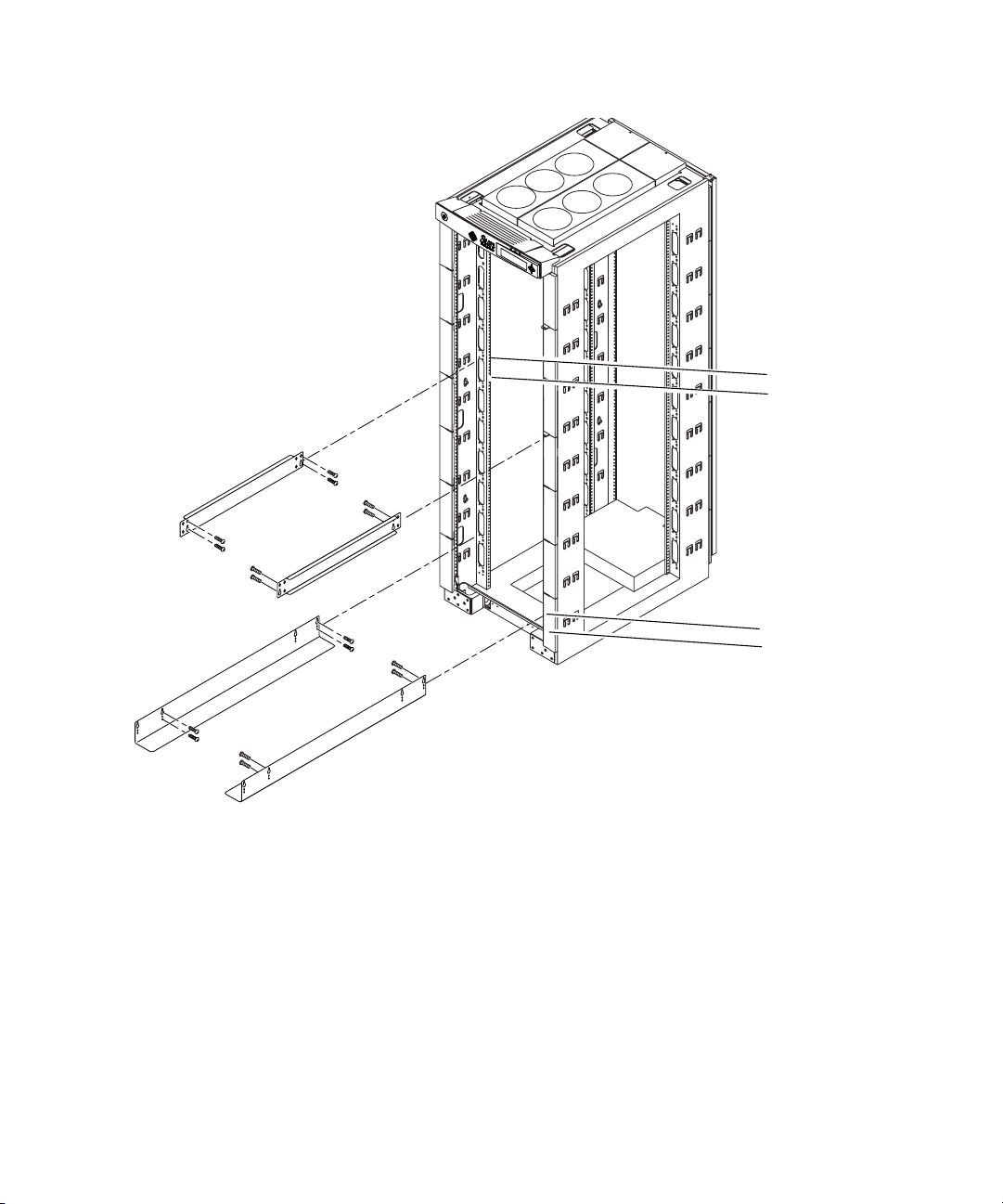
FIGURE 2-1 Rail Installation in Sun Fire Cabinet
Cabinet Hole #68
Cabinet Hole #66
Cabinet Hole #24
Cabinet Hole #21
Chapter 2 Installing the Sun Fire 4800 System into a Sun Fire Cabinet 2-3
Page 28
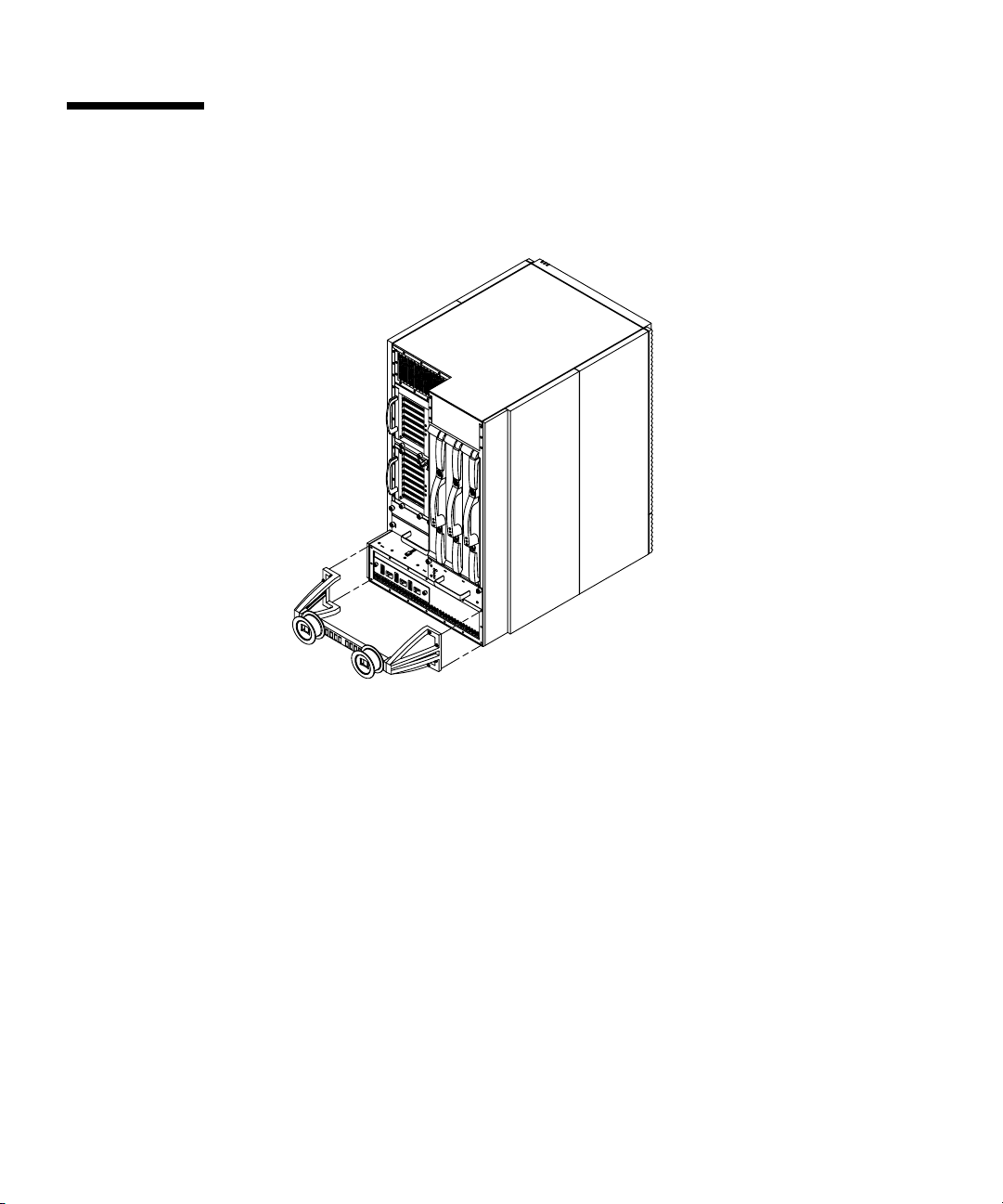
2.3 Removing the Bumper
1. Remove the four M5 screws that hold the bumper to the Sun Fire 4800 system.
FIGURE 2-2 Bumper location on Sun Fire 4800 system
2-4 Sun Fire 4810/4800/3800 Systems Cabinet Mounting Guide • January 2002
Page 29
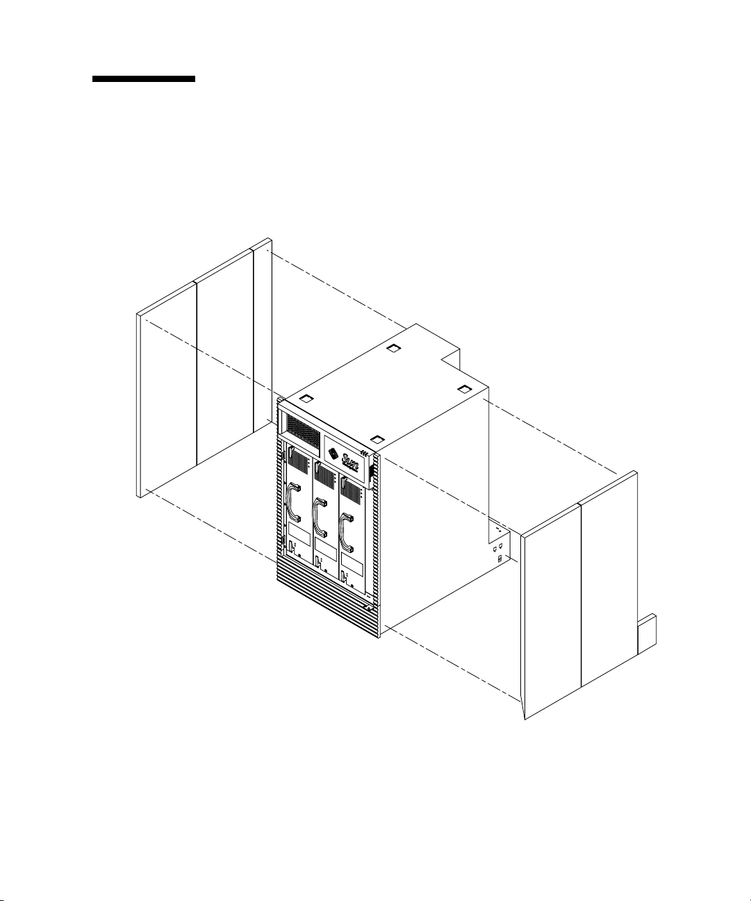
2.4 Removing the Side Panels
1. Pull out on the bottom of the panel while sliding the panel upwards until the
panel snaps out of its locked position.
2. Repeat Step 1 for all six panels.
FIGURE 2-3 Removing Side Panels from the Sun Fire 4800 system
Chapter 2 Installing the Sun Fire 4800 System into a Sun Fire Cabinet 2-5
Page 30

2.5 Removing the Casters
The Sun Fire 4800 system must be elevated above the floor with a computer
equipment lift so the bottom of the system can be accessed.
1. Remove the four M6 screws that hold the caster to the bottom of the system.
2. Repeat Step 1 for all four casters.
2.6 Mounting the Sun Fire 4800 System
1. Locate three power cords close to where the system will be mounted and untie
them from the cabinet so that they will be accessible after the system has been
mounted.
The power cords are pre-installed in the Sun Fire cabinet with one end attached to
the redundant transfer unit (RTU) assemblies.
Note – Refer to the Rackmount Placement Matrix,athttp://docs.sun.com for
power cord cabling information.
Caution – The Sun Fire 4800 system weighs approximately 289 lbs (131.1 kg). To
prevent personal injury, two people are needed to move the system safely into the
cabinet using a computer equipment lift.
Caution – Make sure the cabinet is stabilized before mounting the system and
storage devices. The anti-tilt bar can be used to prevent the cabinet from tilting.
2. Insert the system, from the front, onto the bottom mounting rails in the cabinet
(FIGURE 2-4).
3. Secure the front of the system to the cabinet using four screws.
4. Attach L-brackets to the upper rails using two screws to attach each bracket to the
rails and two screws to attach each bracket to the system.
Facing the rear of the cabinet, the larger L-bracket should be attached to the left side
and the smaller L-bracket to the right side.
2-6 Sun Fire 4810/4800/3800 Systems Cabinet Mounting Guide • January 2002
Page 31
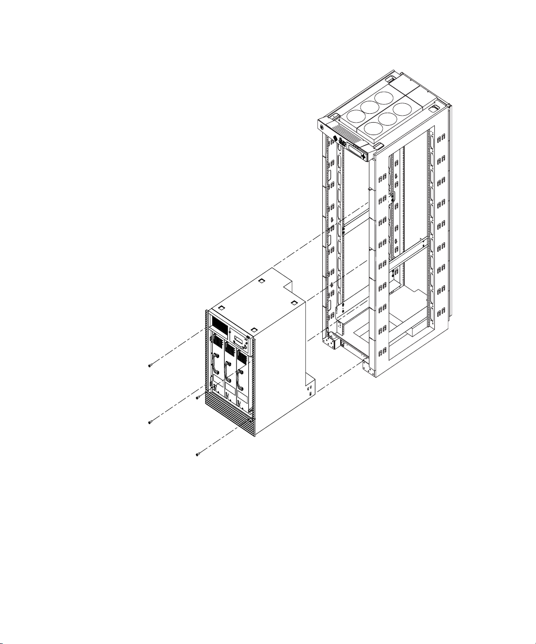
FIGURE 2-4 Mounting the Sun Fire 4800 System into the Sun Fire Cabinet
Chapter 2 Installing the Sun Fire 4800 System into a Sun Fire Cabinet 2-7
Page 32

2.7 Connecting Power Cables to the Sun Fire 4800 System
1. Ensure that each power switch on the Sun Fire cabinet is set to off (FIGURE 2-5).
Note – In a dual RTU configuration, there will be power switches in both the front
and rear of the cabinet. All power switches must be turned off.
2. Ensure that each power switch on the Sun Fire 4800 system is set to off.
3. Connect the previously selected power cord to a power cord socket on the system.
Three power cords should have been untied from the cabinet and moved out of the
way during Step 1 of Section 2.6.
4. Loosen the screw above the power cord socket.
This will loosen the bracket that holds the tie wrap.
5. Position the bracket tightly against the power cord.
6. Tighten the tie wrap around the power cord to keep it from being dislodged.
Make sure the tie wrap is tight. Do not trim excess tie wrap.
7. Tighten the screw above the power cord socket.
8. Repeat Step 3 through Step 7 for each of the three power cords.
Caution – Risk of electric shock. Do NOT turn on AC power to the unit yet.
2-8 Sun Fire 4810/4800/3800 Systems Cabinet Mounting Guide • January 2002
Page 33
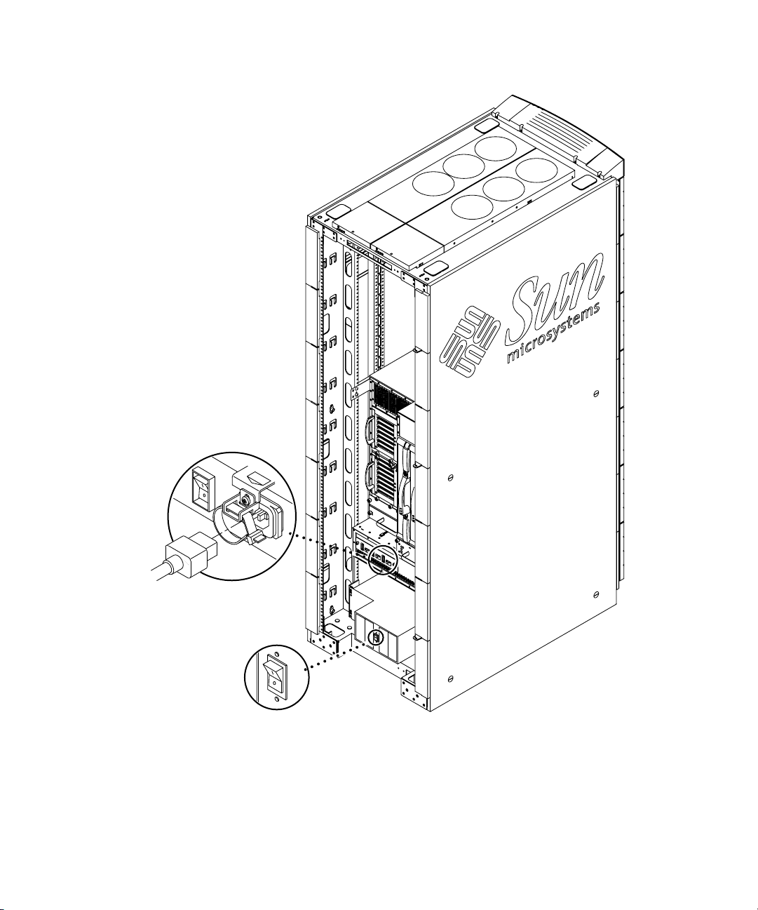
FIGURE 2-5 Power Switch Locations on the Cabinet Mounted Sun Fire 4800 System
Chapter 2 Installing the Sun Fire 4800 System into a Sun Fire Cabinet 2-9
Page 34

2.8 Attaching Cabinet Front Panels
1. Place the first cabinet front panel as close as possible to the top of the system, and
secure the panel to the Sun Fire cabinet by tightening the screws through the left
and right sides of the panel.
2. Secure subsequent panels by tightening the screws through the left and right
front of each panel (
Place each front panel as close to the one below as possible. Use different sized front
panels as necessary to completely fill in the gap above the system. If unable to fill in
the entire gap leave the smallest possible gap at the top of the cabinet.
Note – The large cabinet front panels are not simply cosmetic, they prevent hot air
expelled from the rear of the cabinet from reentering the system from the front.
3. Secure small cosmetic panels on the cabinet adjacent to the system.
FIGURE 2-6).
2-10 Sun Fire 4810/4800/3800 Systems Cabinet Mounting Guide • January 2002
Page 35
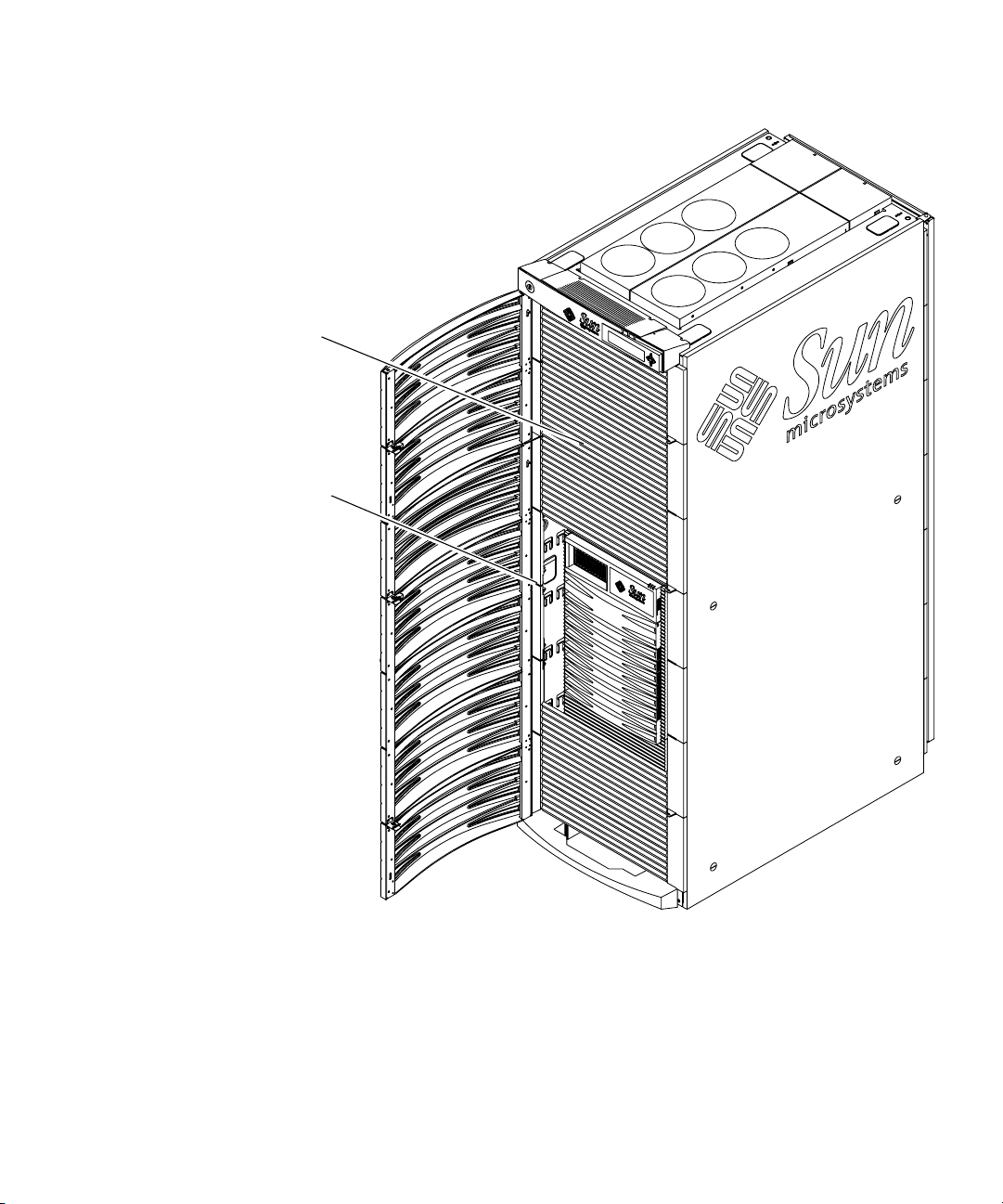
Cabinet Front Panels
Cosmetic Front Panels
FIGURE 2-6 Cabinet Front Panel Locations
Chapter 2 Installing the Sun Fire 4800 System into a Sun Fire Cabinet 2-11
Page 36
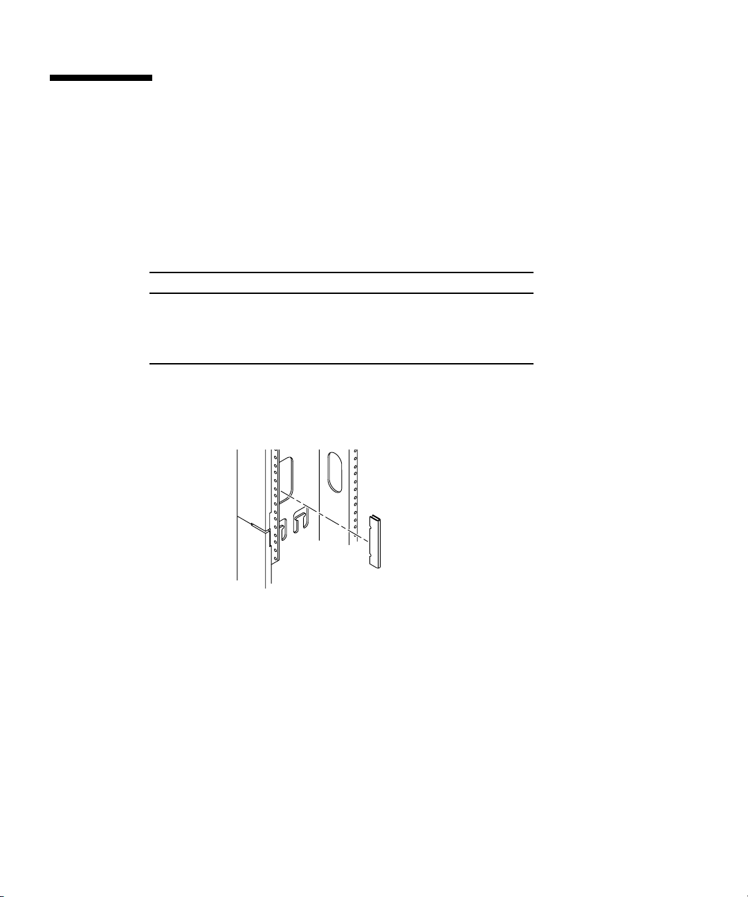
2.9 Attaching Cabinet Guards
The cabinet guards are designed to protect against injuries that may occur when
boards are removed from the system.
1. Locate the cabinet guard hole locations on the rear of the Sun Fire cabinet using
TABLE 2-1.
TABLE 2-1 Sun Fire 4800 Cabinet Guard Locations
Left Side of Cabinet Right Side of Cabinet
Top notch in cabinet hole #59
Top notch in cabinet hole #45
Top notch in cabinet hole #10
2. Align the upper “v” notch on the cabinet guard with the appropriate numbered
hole, and press firmly in the middle of the guard until it stops against the edge of
the cabinet (
FIGURE 2-7).
Top notch in cabinet hole #
Top notch in cabinet hole #
Top notch in cabinet hole #
58
49
10
FIGURE 2-7 Cabinet Guard Installation
2-12 Sun Fire 4810/4800/3800 Systems Cabinet Mounting Guide • January 2002
Page 37

2.10 Connecting the System Controller to the FrameManager
The Y-serial cable allows the primary System Controller board to be accessed by the
Sun Fire cabinet FrameManager and a serial cable terminal connection
simultaneously.
1. Connect the single end of the Y-serial cable (located in the shipping kit that came
with the system) to the serial port on the primary system controller.
2. Connect the ’A’ end of the Y-serial cable to the serial cable terminal connection (if
any).
3. Connect the ’B’ end of the Y-serial cable to the P2 Cable.
The P2 cable is pre connected to the FrameManager and secured among the power
cables on the right side of the Sun Fire cabinet.
4. To continue with the installation, refer to the Sun Fire 4810/4800/3800 Systems
Installation Guide Section 3.3.
Chapter 2 Installing the Sun Fire 4800 System into a Sun Fire Cabinet 2-13
Page 38

2-14 Sun Fire 4810/4800/3800 Systems Cabinet Mounting Guide • January 2002
Page 39

CHAPTER
3
Installing the Sun Fire 3800System
into a Sun Fire Cabinet
The Sun Fire 3800 system is a standalone unit designed to be mounted in a rack. All
the hardware necessary to mount the system in a Sun Fire cabinet is included in the
shipping carton. The Sun Fire cabinet can house three Sun Fire 3800 systems.
■ Tools—page 3-1
■ Mounting the Rails—page 3-2
■ Installing the Cable Raceways—page 3-4
■ Mounting the Sun Fire 3800 System—page 3-6
■ Installing the Sun Fire Cabinet Extension Brackets—page 3-8
■ Connecting Power Cables to the Sun Fire 3800 System—page 3-10
■ Attaching Cabinet Front Panels—page 3-12
■ Attaching Cabinet Guards—page 3-14
■ Connecting the System Controller to the FrameManager—page 3-15
3.1 Tools
You need the following tools:
■ Screwdriver, Phillips No. 2.
Caution – The Sun Fire 3800 system weighs approximately 200 lbs (90.7 kg). To
prevent personal injury, two people are needed to move the system safely into the
cabinet using a computer equipment lift rated for 200 lbs or greater.
3-1
Page 40
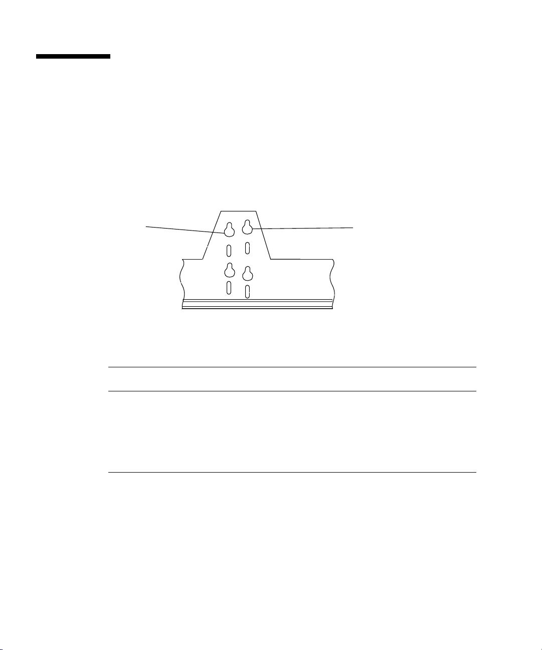
3.2 Mounting the Rails
1. Locate the rails for the system.
With the orientation from the front of the system, each rail is labeled “RIGHT” or
“LEFT”
Each rail has sixteen holes; eight are load-bearing hanger holes and eight are slots.
The hanger holes used to mount a Sun Fire 3800 system are identified in
FIGURE 3-1.
Hanger hole #2
FIGURE 3-1 Rail Hole Identification
TABLE 3-1 Sun Fire 3800 System Rackmounting Order
Sun Fire 3800 System
Mounting Position Hole Count From Bottom of Cabinet
System #3 (Top) Top screw: rail hanger hole #4 at cabinet hole #78
Bottom screw: in slot at cabinet hole #72
System #2 (middle) Top screw: rail hanger hole #2 at cabinet hole #52
Bottom screw: in slot at cabinet hole #47
System #1 (bottom) Top screw: rail hanger hole #4 at cabinet hole #26
Bottom screw: in slot at cabinet hole #20
Hanger hole #4
3-2 Sun Fire 4810/4800/3800 Systems Cabinet Mounting Guide • January 2002
Page 41
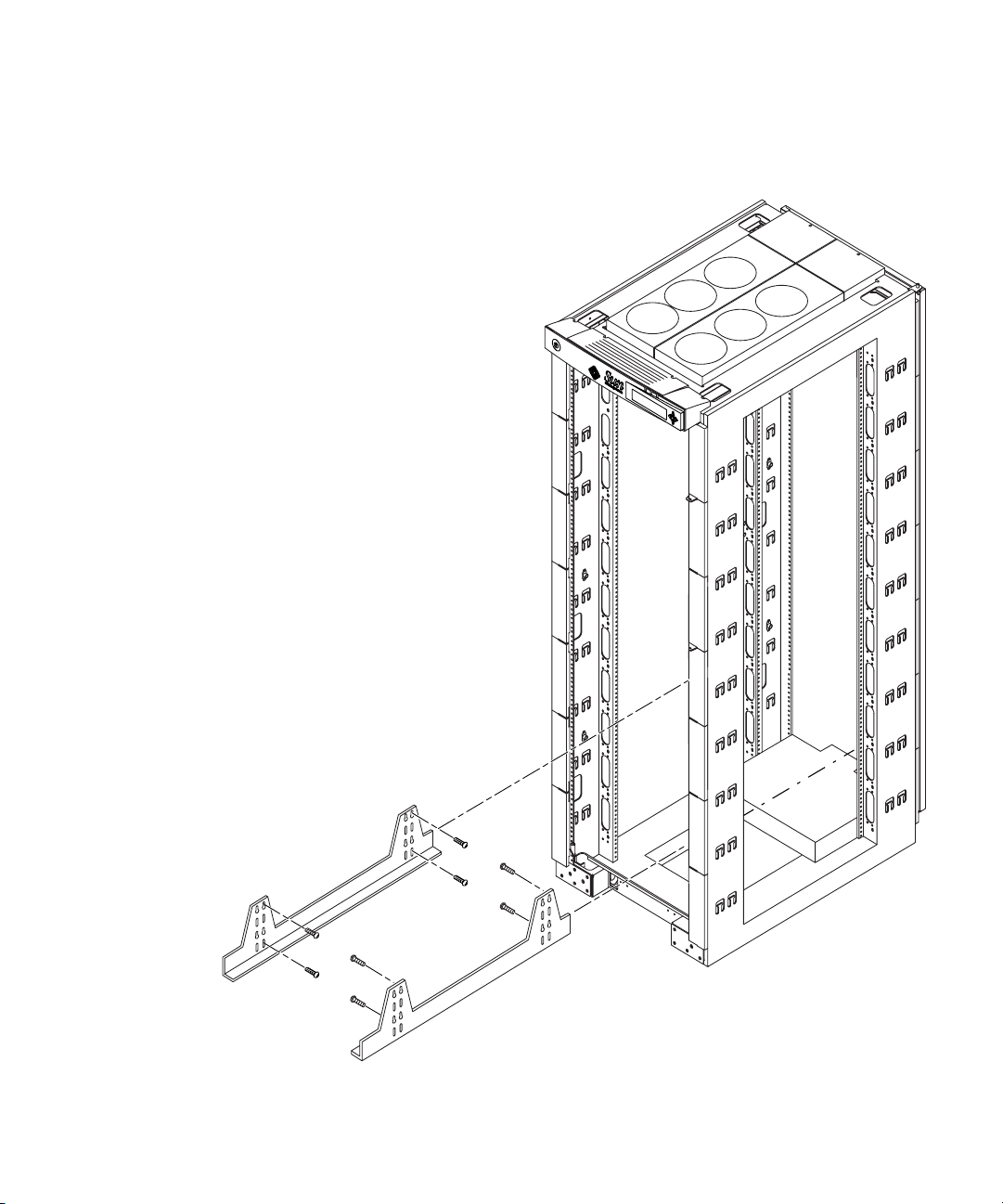
2. Mount the rails to the Sun Fire cabinet using four mounting screws for each rail
(FIGURE 3-2).
Rail and cabinet hole information is listed in TABLE 3-1.
FIGURE 3-2 Mounting Bracket Installation in Sun Fire Cabinet
Chapter 3 Installing the Sun Fire 3800 System into a Sun Fire Cabinet 3-3
Page 42

3.3 Installing the Cable Raceways
1. Locate the cable raceway hole locations for the system.
TABLE 3-2 Sun Fire 3800 System Cable Raceway Locations
Sun Fire 3800 System Cable
Raceway Positions
System #3 (top)
System #2 (middle)
System #1 (bottom)
Grommet Hole Count
From Bottom of Rack
8 and 9
6 and 7
3 and 4
Start counting from the bottom of the cabinet for the cable raceway holes.
2. Insert the cable raceway at an angle and mate it to the appropriate grommet hole
at the rear of the cabinet (
FIGURE 3-3).
3. Mate the cable raceway to the appropriate grommet hole at the front of the
cabinet.
3-4 Sun Fire 4810/4800/3800 Systems Cabinet Mounting Guide • January 2002
Page 43
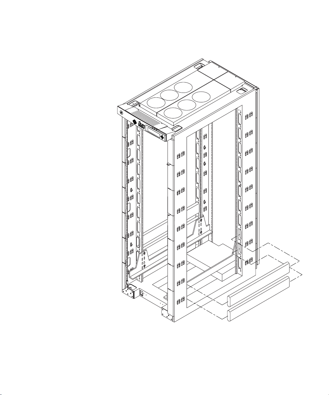
4. Repeat Step 2 through Step 4 until you have installed two raceways on each side
of the Sun Fire cabinet.
FIGURE 3-3 Cable Raceway Installation
Chapter 3 Installing the Sun Fire 3800 System into a Sun Fire Cabinet 3-5
Page 44

3.4 Mounting the Sun Fire 3800 System
1. Locate three power cords close to where the system will be mounted and untie
them from the cabinet so that they will be accessible after the system has been
mounted.
The power cords are pre-installed in the Sun Fire cabinet with one end already
attached to the redundant transfer unit (RTU) assemblies.
Note – Refer to the Rackmount Placement Matrix,athttp://docs.sun.com for
power cord cabling information.
Caution – The Sun Fire 3800 system weighs approximately 200 lbs (90.7 kg). To
prevent personal injury, two people are needed to move the system safely into the
cabinet using a computer equipment lift.
Caution – Make sure the cabinet is stabilized before mounting the system and
storage devices. The anti-tilt bar can be used to prevent the cabinet from tilting.
2. Insert the Sun Fire 3800 system onto the brackets in the Sun Fire cabinet.
3. Secure the front of the system to the cabinet with six screws (three on each side)
(
FIGURE 3-4).
4. Secure the back-stop bracket to the rear of the system with two screws.
Make sure that the bracket is flush with the top of the system.
5. Secure the back-stop bracket to the cabinet with four screws (two on each side).
3-6 Sun Fire 4810/4800/3800 Systems Cabinet Mounting Guide • January 2002
Page 45
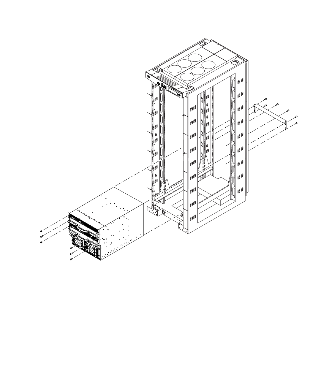
FIGURE 3-4 Securing the Sun Fire 3800 System in the Sun Fire Cabinet
Chapter 3 Installing the Sun Fire 3800 System into a Sun Fire Cabinet 3-7
Page 46

3.5 Installing the Sun Fire Cabinet Extension Brackets
The cabinet extension brackets add an additional 32 pounds (14.5 kilo) to the weight
of the cabinet and they extend the cabinet depth by 4 in. (10.16 cm).
1. Remove the top trim panel from the rear of the Sun Fire cabinet.
The top trim is attached with two M4 screws. Set these screws aside to avoid
confusion with the similar sized 10-32 screws.
2. Release the catches and remove the kick-panel.
3. Remove the kick-panel brackets.
The kick-panel brackets are attached with two screws each.
4. Remove the rear door hinge bolts and remove the door.
Set all four 10-32 screws aside.
5. Remove the door catch.
Set the two 10-32 screws aside.
6. Lightly tighten the side extender screws (eight per side) and hang the extender
brackets on the screws.
The screws should extend out of the cabinet so that the door can hang easily on
them.
7. Install the top extender bracket.
The top extender bracket attaches down from the top of the cabinet with two screws.
Use the two M4 screws saved from Step 1.
8. Secure the side extender screws (eight per side) and install cosmetic plugs.
The cosmetic plugs are cosmetic and optional.
9. Secure the rear door hinge bolts to the side extender brackets using four 10-32
screws.
10. Reinstall the door catch to the side extender brackets using the two 10-32 screws.
11. Snap the bottom bracket into place.
3-8 Sun Fire 4810/4800/3800 Systems Cabinet Mounting Guide • January 2002
Page 47
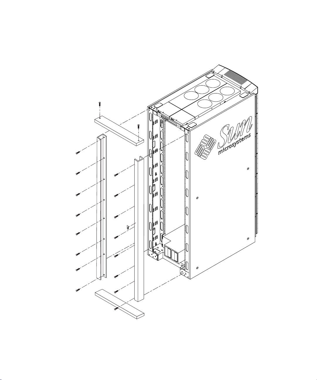
FIGURE 3-5 Installing Sun Fire Cabinet Extension Brackets
Chapter 3 Installing the Sun Fire 3800 System into a Sun Fire Cabinet 3-9
Page 48

3.6 Connecting Power Cables to the Sun Fire 3800 System
1. Ensure that each power switch on the Sun Fire cabinet is set to off (FIGURE 3-6).
Note – In a dual RTU configuration, there will be power switches in both the front
and rear of the cabinet. All power switches must be turned off.
2. Ensure that each power supply switch on the system is set to off.
3. Connect the previously selected power cords to the power cord sockets on system.
The power cords should have been untied from the cabinet and moved out of the
way during Step 1 in Section 3.4.
4. Tighten the tie wrap around each power cord and power supply handle to keep
them from being dislodged.
Make sure the tie wrap is tight. Do not trim excess tie wrap.
Caution – Risk of electric shock. Do NOT turn on AC power to the unit yet.
3-10 Sun Fire 4810/4800/3800 Systems Cabinet Mounting Guide • January 2002
Page 49
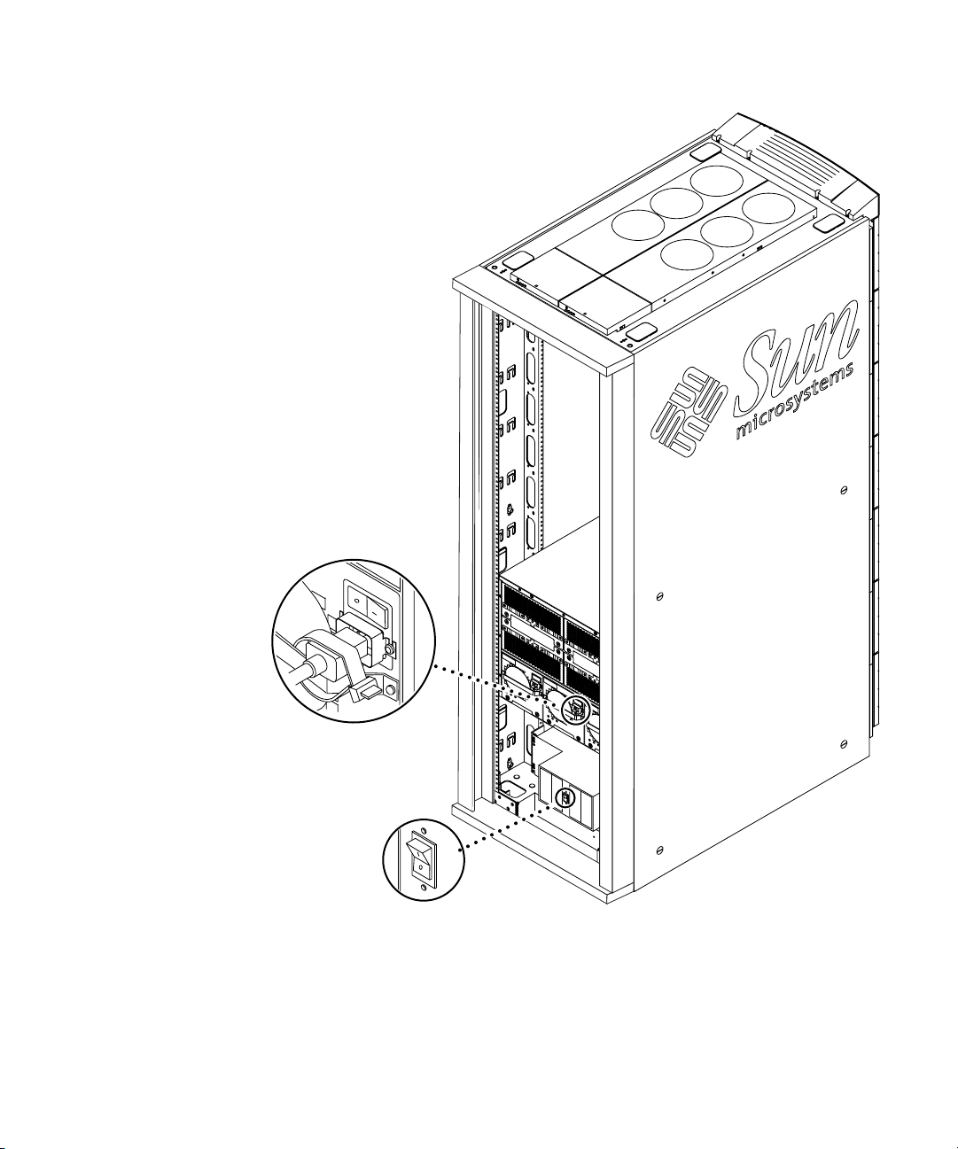
FIGURE 3-6 Power Switch Locations on the Cabinet Mounted Sun Fire 3800 System
Chapter 3 Installing the Sun Fire 3800 System into a Sun Fire Cabinet 3-11
Page 50

3.7 Attaching Cabinet Front Panels
1. Place the first cabinet front panel as close as possible to the top of the system, and
secure the panel to the Sun Fire cabinet by tightening the screws through the left
and right sides of the panel.
2. Secure subsequent panels by tightening the screws through the left and right
front of each panel (
Place each front panel as close to the one below as possible. Use different sized front
panels as necessary to completely fill in the gap above the system. If unable to fill in
the entire gap leave the smallest possible gap at the top of the cabinet.
Note – The large cabinet front panels are not simply cosmetic, they prevent hot air
expelled from the rear of the cabinet from reentering the system from the front.
3. Secure small cosmetic panels on the cabinet adjacent to the system.
FIGURE 3-7).
3-12 Sun Fire 4810/4800/3800 Systems Cabinet Mounting Guide • January 2002
Page 51
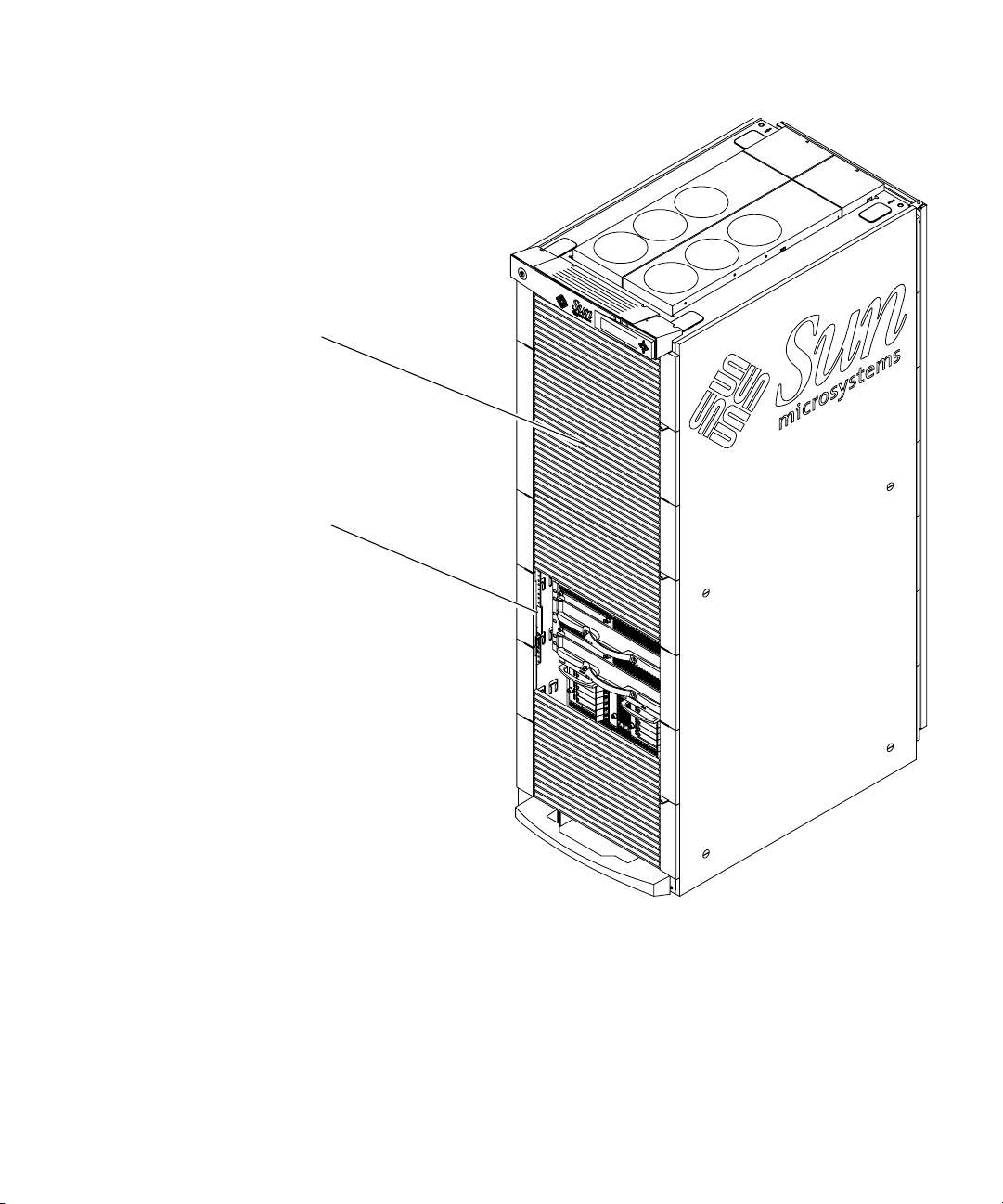
Cabinet Front Panels
Cosmetic Front Panels
FIGURE 3-7 Cabinet Front Panel Locations
Chapter 3 Installing the Sun Fire 3800 System into a Sun Fire Cabinet 3-13
Page 52
3.8 Attaching Cabinet Guards
The cabinet guards are designed to protect against injuries that may occur when
boards are removed from the system.
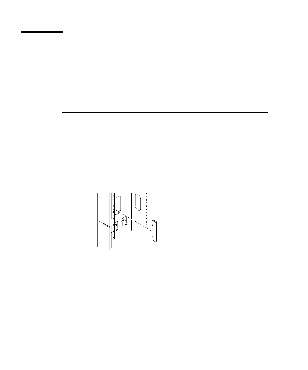
1. Locate the cabinet guard hole locations on the rear of the Sun Fire cabinet using
TABLE 3-3.
TABLE 3-3 Sun Fire 3800 Cabinet Guard Locations
Sun Fire 3800 System
Mounting Position Left Side of Cabinet Right Side of Cabinet
System #3 (Top) Top notch in cabinet hole #79
System #2 (middle) Top notch in cabinet hole #53
System #1 (bottom) Top notch in cabinet hole #27
2. Align the upper “v” notch on the cabinet guard with the appropriate numbered
hole, and press firmly in the middle of the guard until it stops against the edge of
the cabinet (
FIGURE 3-8).
Top notch in cabinet hole
Top notch in cabinet hole
Top notch in cabinet hole
#79
#53
#27
FIGURE 3-8 Cabinet Guard Installation
3-14 Sun Fire 4810/4800/3800 Systems Cabinet Mounting Guide • January 2002
Page 53

3.9 Connecting the System Controller to the FrameManager
The Y-serial cable allows the primary System Controller board to be accessed by the
Sun Fire cabinet FrameManager and a serial cable terminal connection
simultaneously.
1. Connect the single end of the Y-serial cable (located in the shipping kit that came
with the system) to the serial port on the primary system controller.
2. Connect the ’A’ end of the Y-serial cable to the serial cable terminal connection (if
any).
3. Connect the ’B’ end of the Y-serial cable to the P2 Cable.
The P2 cable is pre connected to the FrameManager and secured among the power
cables on the right side of the Sun Fire cabinet.
4. To continue with the installation, refer to the Sun Fire 4810/4800/3800 Systems
Installation Guide Section 4.3.
Chapter 3 Installing the Sun Fire 3800 System into a Sun Fire Cabinet 3-15
Page 54

3-16 Sun Fire 4810/4800/3800 Systems Cabinet Mounting Guide • January 2002
Page 55

CHAPTER
A
Regulatory Compliance Statements
Your Sun product is marked to indicate its compliance class:
■ Federal Communications Commission (FCC) — USA
■ Industry Canada Equipment Standard for Digital Equipment (ICES-003) - Canada
■ Voluntary Control Council for Interference (VCCI) — Japan
■ Bureau of Standards Metrology and Inspection (BSMI) — Taiwan
Please read the appropriate section that corresponds to the marking on your Sun
product before attempting to install the product.
A.1 FCC Class A Notice
This device complies with Part 15 of the FCC Rules. Operation is subject to the
following two conditions:
1. This device may not cause harmful interference.
2. This device must accept any interference received, including interference that
may cause undesired operation.
Note – This equipment has been tested and found to comply with the limits for a
Class A digital device, pursuant to Part 15 of the FCC Rules. These limits are
designed to provide reasonable protection against harmful interference when the
equipment is operated in a commercial environment. This equipment generates,
uses, and can radiate radio frequency energy, and if it is not installed and used in
accordance with the instruction manual, it may cause harmful interference to radio
communications. Operation of this equipment in a residential area is likely to cause
harmful interference, in which case the user will be required to correct the
interference at his own expense.
A-1
Page 56

Shielded Cables: Connections between the workstation and peripherals must be
made using shielded cables to comply with FCC radio frequency emission limits.
Networking connections can be made using unshielded twisted-pair (UTP) cables.
Modifications: Any modifications made to this device that are not approved by Sun
Microsystems, Inc. may void the authority granted to the user by the FCC to operate
this equipment.
A.2 FCC Class B Notice
This device complies with Part 15 of the FCC Rules. Operation is subject to the
following two conditions:
1. This device may not cause harmful interference.
2. This device must accept any interference received, including interference that
may cause undesired operation.
Note – This equipment has been tested and found to comply with the limits for a
Class B digital device, pursuant to Part 15 of the FCC Rules. These limits are
designed to provide reasonable protection against harmful interference in a
residential installation. This equipment generates, uses and can radiate radio
frequency energy and, if not installed and used in accordance with the instructions,
may cause harmful interference to radio communications. However, there is no
guarantee that interference will not occur in a particular installation. If this
equipment does cause harmful interference to radio or television reception, which
can be determined by turning the equipment off and on, the user is encouraged to
try to correct the interference by one or more of the following measures:
■ Reorient or relocate the receiving antenna.
■ Increase the separation between the equipment and receiver.
■ Connect the equipment into an outlet on a circuit different from that to which the
receiver is connected.
■ Consult the dealer or an experienced radio/television technician for help.
Shielded Cables: Connections between the workstation and peripherals must be
made using shielded cables in order to maintain compliance with FCC radio
frequency emission limits. Networking connections can be made using unshielded
twisted pair (UTP) cables.
Modifications: Any modifications made to this device that are not approved by Sun
Microsystems, Inc. may void the authority granted to the user by the FCC to operate
this equipment.
A-2 Sun Fire 4810/4800/3800 Systems Cabinet Mounting Guide • January 2002
Page 57
A.3 ICES-003 Class A Notice - Avis NMB-
003, Classe A
This Class A digital apparatus complies with Canadian ICES-003.
Cet appareil numérique de la classe A est conforme à la norme NMB-003 du
Canada.
A.4 ICES-003 Class B Notice - Avis NMB-003,
Classe B
This Class B digital apparatus complies with Canadian ICES-003.
Cet appareil numérique de la classe B est conforme à la norme NMB-003 du Canada.
Chapter A Regulatory Compliance Statements A-3
Page 58
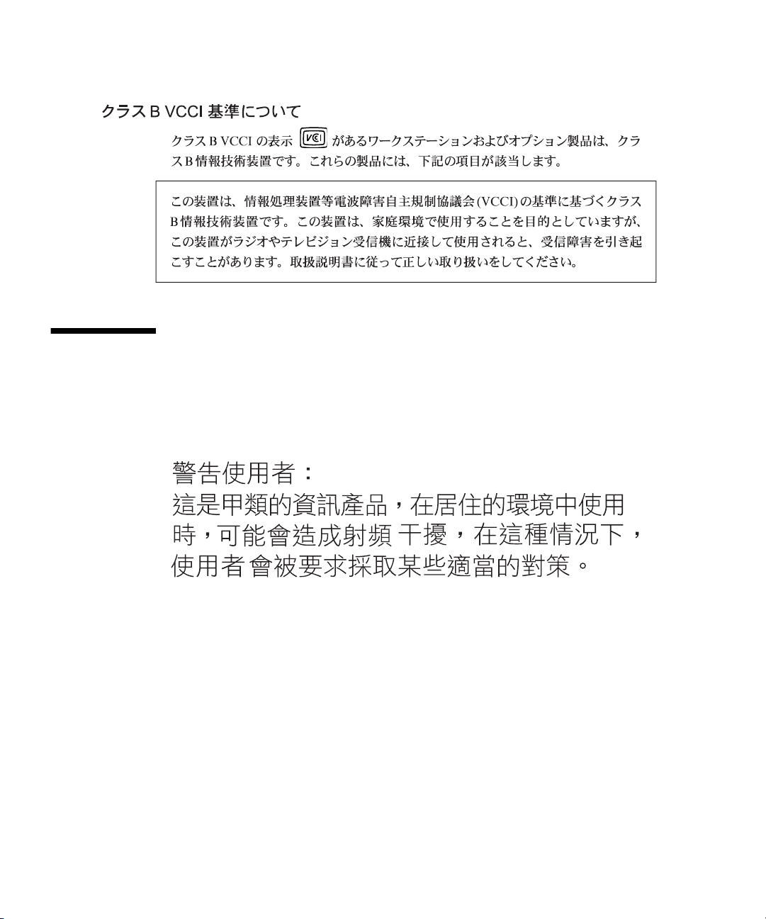
A.5 BSMI Class A Notice
The following statement is applicable to products shipped to Taiwan and marked as
Class A on the product compliance label.
A-4 Sun Fire 4810/4800/3800 Systems Cabinet Mounting Guide • January 2002
Page 59
APPENDIX
B
Compliance Statements
Safety Agency Compliance
Statements
Read this section before beginning any procedure. The
following text provides safety precautions to follow
when installing a Sun Microsystems product.
Safety Precautions
For your protection, observe the following safety
precautions when setting up your equipment:
• Follow all cautions and instructions marked on the
equipment.
• Ensure that the voltage and frequency of your power
source match the voltage and frequency inscribed on
the equipment’s electrical rating label.
• Never push objects of any kind through openings in
the equipment. Dangerous voltages may be present.
Conductive foreign objects could produce a short
circuit that could cause fire, electric shock, or damage
to your equipment.
Symbols
The following symbols may appear in this book:
Caution – There is risk of personal injury and
equipment damage. Follow the instructions.
!
Modifications to Equipment
Do not make mechanical or electrical modifications to the
equipment. Sun Microsystems is not responsible for
regulatory compliance of a modified Sun product.
Placement of a Sun Product
Caution – Do not block or cover the openings of
your Sun product. Never place a Sun product
!
near a radiator or heat register. Failure to follow
these guidelines can cause overheating and affect
the reliability of your Sun product.
SELV Compliance
Safety status of I/O connections comply to SELV
requirements.
Power Cord Connection
Caution – Sun products are designed to work
with single-phase power systems having a
grounded neutral conductor. To reduce the risk of
electric shock, do not plug Sun products into any
other type of power system. Contact your
facilities manager or a qualified electrician if you
are not sure what type of power is supplied to
your building.
Caution – Hot surface. Avoid contact. Surfaces
are hot and may cause personal injury if touched.
Caution – Hazardous voltages are present. To
reduce the risk of electric shock and danger to
personal health, follow the instructions.
Caution – Not all power cords have the same
current ratings. Household extension cords do
not have overload protection and are not meant
for use with computer systems. Do not use
household extension cords with your Sun
product.
B-1
Page 60
Caution – Your Sun product is shipped with a
grounding type (three-wire) power cord. To
reduce the risk of electric shock, always plug the
cord into a grounded power outlet.
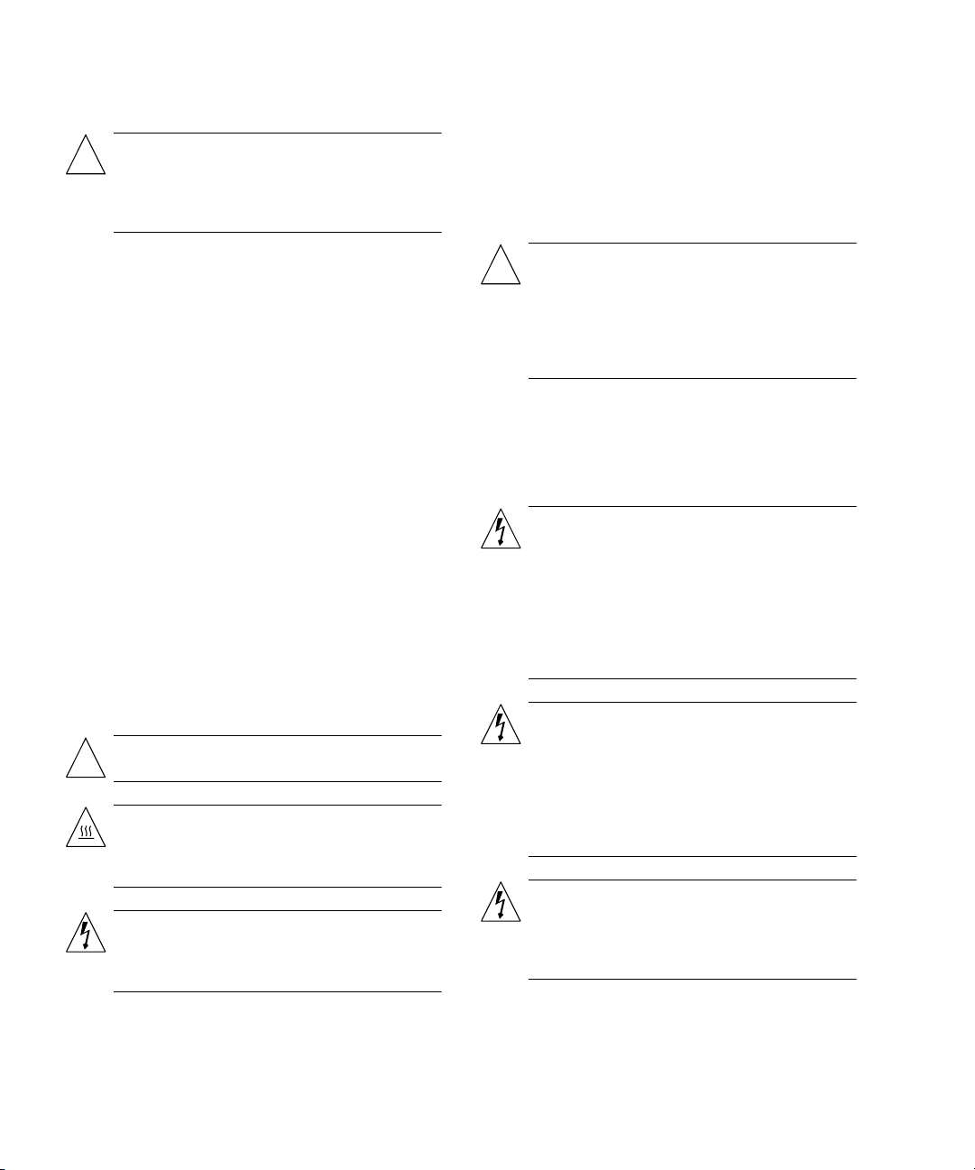
Laser Compliance Notice
Sun products that use laser technology comply with
Class 1 laser requirements.
Caution – In order to remove all power from this
unit, turn off all power switches
The following caution applies only to devices with a
Standby power switch:
Caution – The power switch of this product
functions as a standby type device only. The
power cord serves as the primary disconnect
device for the system. Be sure to plug the power
cord into a grounded power outlet that is nearby
the system and is readily accessible. Do not
connect the power cord when the power supply
has been removed from the system chassis.
Lithium Battery
Caution – On Sun CPU boards, there is a lithium
battery molded into the real-time clock, SGS No.
!
MK48T59Y, MK48T594-70PCIU, MK48TXXB-XX,
MK48T18-XXXPCZ, M48T59W-XXXPCZ, or
MK48T08. Batteries are not customer replaceable
parts. They may explode if mishandled. Do not
dispose of the battery in fire. Do not disassemble
it or attempt to recharge it.
System Unit Cover
If you must remove the cover of your Sun computer
system unit in order to add cards, memory, or internal
storage devices, be sure to replace the top cover before
powering up your computer system.
Caution – Do not operate Sun products without
the top cover in place. Failure to take this
!
precaution may result in personal injury and
system damage.
Class 1 Laser Product
Luokan 1 Laserlaite
Klasse 1 Laser Apparat
Laser Klasse 1
DVD-ROM
Caution – Use of controls, adjustments, or the
performance of procedures other than those
!
specified herein may result in hazardous
radiation exposure.
Einhaltung sicherheitsbehördlicher
Vorschriften
Auf dieser Seite werden Sicherheitsrichtlinien
beschrieben, die bei der Installation von Sun-Produkten
zu beachten sind.
Sicherheitsvorkehrungen
Treffen Sie zu Ihrem eigenen Schutz die folgenden
Sicherheitsvorkehrungen, wenn Sie Ihr Gerät installieren:
• Beachten Sie alle auf den Geräten angebrachten
Warnhinweise und Anweisungen.
• Vergewissern Sie sich, daß Spannung und Frequenz
Ihrer Stromquelle mit der Spannung und Frequenz
übereinstimmen, die auf dem Etikett mit den
elektrischen Nennwerten des Geräts angegeben sind.
• Stecken Sie auf keinen Fall irgendwelche Gegenstände
in Öffnungen in den Geräten. Leitfähige Gegenstände
könnten aufgrund der möglicherweise vorliegenden
gefährlichen Spannungen einen Kurzschluß
verursachen, der einen Brand, Stromschlag oder
Geräteschaden herbeiführen kann.
Symbole
Die Symbole in diesem Handbuch haben folgende
Bedeutung:
Achtung – Gefahr von Verletzung und
Geräteschaden. Befolgen Sie die Anweisungen.
!
B-2 Sun Fire 4810/4800/3800 Systems Installation Guide • January 2002
Page 61
Achtung – Hohe Temperatur. Nicht berühren, da
Verletzungsgefahr durch heiße Oberfläche
besteht.
Achtung – Gefährliche Spannungen.
Anweisungen befolgen, um Stromschläge und
Verletzungen zu vermeiden.
Aufstellung von Sun-Geräten
Achtung – Um den zuverlässigen Betrieb Ihres
Sun-Geräts zu gewährleisten und es vor
!
Überhitzung zu schützen, dürfen die Öffnungen
im Gerät nicht blockiert oder verdeckt werden.
Sun-Produkte sollten niemals in der Nähe von
Heizkörpern oder Heizluftklappen aufgestellt
werden.
Einhaltung der SELV-Richtlinien
Die Sicherung der I/O-Verbindungen entspricht den
Anforderungen der SELV-Spezifikation.
Anschluß des Netzkabels
Achtung – Sun-Produkte sind für den Betrieb an
Einphasen-Stromnetzen mit geerdetem Nulleiter
vorgesehen. Um die Stromschlaggefahr zu
reduzieren, schließen Sie Sun-Produkte nicht an
andere Stromquellen an. Ihr Betriebsleiter oder
ein qualifizierter Elektriker kann Ihnen die Daten
zur Stromversorgung in Ihrem Gebäude geben.
Die folgende Warnung gilt nur für Geräte mit
Wartezustand-Netzschalter:
Achtung – Der Ein/Aus-Schalter dieses Geräts
schaltet nur auf Wartezustand (Stand-By-Modus).
Um die Stromzufuhr zum Gerät vollständig zu
unterbrechen, müssen Sie das Netzkabel von der
Steckdose abziehen. Schließen Sie den Stecker des
Netzkabels an eine in der Nähe befindliche, frei
zugängliche, geerdete Netzsteckdose an.
Schließen Sie das Netzkabel nicht an, wenn das
Netzteil aus der Systemeinheit entfernt wurde.
Lithiumbatterie
Achtung – CPU-Karten von Sun verfügen über
eine Echtzeituhr mit integrierter Lithiumbatterie
!
(Teile-Nr. MK48T59Y, MK48T594-70PCIU,
MK48TXXB-XX, MK48T18-XXXPCZ,
M48T59W-XXXPCZ, oder MK48T08). Diese
Batterie darf nur von einem qualifizierten
Servicetechniker ausgewechselt werden, da sie
bei falscher Handhabung explodieren kann.
Werfen Sie die Batterie nicht ins Feuer. Versuchen
Sie auf keinen Fall, die Batterie auszubauen oder
wiederaufzuladen.
Gehäuseabdeckung
Sie müssen die obere Abdeckung Ihres Sun-Systems
entfernen, um interne Komponenten wie Karten,
Speicherchips oder Massenspeicher hinzuzufügen.
Bringen Sie die obere Gehäuseabdeckung wieder an,
bevor Sie Ihr System einschalten.
Achtung – Nicht alle Netzkabel haben die
gleichen Nennwerte. Herkömmliche, im Haushalt
verwendete Verlängerungskabel besitzen keinen
Überlastungsschutz und sind daher für
Computersysteme nicht geeignet.
Achtung – Ihr Sun-Gerät wird mit einem
dreiadrigen Netzkabel für geerdete
Netzsteckdosen geliefert. Um die Gefahr eines
Stromschlags zu reduzieren, schließen Sie das
Kabel nur an eine fachgerecht verlegte, geerdete
Steckdose an.
Achtung – Schalten Sie alle Stromschalter ab,
damit die Stromversorgung für das Gerät völlig
unterbrochen wird.
Achtung – Bei Betrieb des Systems ohne obere
Abdeckung besteht die Gefahr von Stromschlag
!
und Systemschäden.
Einhaltung der Richtlinien für Laser
Sun-Produkte, die mit Laser-Technologie arbeiten,
entsprechen den Anforderungen der Laser Klasse 1.
Class 1 Laser Product
Luokan 1 Laserlaite
Klasse 1 Laser Apparat
Laser Klasse 1
Appendix B Compliance Statements B-3
Page 62
DVD-ROM
Warnung – Die Verwendung von anderen
Steuerungen und Einstellungen oder die
!
Durchfhrung von Prozeduren, die von den hier
beschriebenen abweichen, knnen gefhrliche
Strahlungen zur Folge haben.
Modification du matériel
Ne pas apporter de modification mécanique ou
électrique au matériel. Sun Microsystems n’est pas
responsable de la conformité réglementaire d’un produit
Sun qui a été modifié.
Positionnement d’un produit Sun
Conformité aux normes de sécurité
Ce texte traite des mesures de sécurité qu’il convient de
prendre pour l’installation d’un produit Sun
Microsystems.
Mesures de sécurité
Pour votre protection, veuillez prendre les précautions
suivantes pendant l’installation du matériel :
• Suivre tous les avertissements et toutes les instructions
inscrites sur le matériel.
• Vérifier que la tension et la fréquence de la source
d’alimentation électrique correspondent à la tension et
à la fréquence indiquées sur l’étiquette de classification
de l’appareil.
• Ne jamais introduire d’objets quels qu’ils soient dans
une des ouvertures de l’appareil. Vous pourriez vous
trouver en présence de hautes tensions dangereuses.
Tout objet conducteur introduit de la sorte pourrait
produire un court-circuit qui entraînerait des flammes,
des risques d’électrocution ou des dégâts matériels.
Symboles
Vous trouverez ci-dessous la signification des différents
symboles utilisés :
Attention : risques de blessures corporelles et de
dégâts matériels. Veuillez suivre les instructions.
!
Attention : surface à température élevée. Evitez le
contact. La température des surfaces est élevée et
leur contact peut provoquer des blessures
corporelles.
Attention : présence de tensions dangereuses.
Pour éviter les risques d’électrocution et de
danger pour la santé physique, veuillez suivre les
instructions.
Attention : pour assurer le bon fonctionnement
de votre produit Sun et pour l’empêcher de
!
surchauffer, il convient de ne pas obstruer ni
recouvrir les ouvertures prévues dans l’appareil.
Un produit Sun ne doit jamais être placé à
proximité d’un radiateur ou d’une source de
chaleur.
Conformité SELV
Sécurité : les raccordements E/S sont conformes aux
normes SELV.
Connexion du cordon d’alimentation
Attention : les produits Sun sont conçus pour
fonctionner avec des alimentations monophasées
munies d’un conducteur neutre mis à la terre.
Pour écarter les risques d’électrocution, ne pas
brancher de produit Sun dans un autre type
d’alimentation secteur. En cas de doute quant au
type d’alimentation électrique du local, veuillez
vous adresser au directeur de l’exploitation ou à
un électricien qualifié.
Attention : tous les cordons d’alimentation n’ont
pas forcément la même puissance nominale en
matière de courant. Les rallonges d’usage
domestique n’offrent pas de protection contre les
surcharges et ne sont pas prévues pour les
systèmes d’ordinateurs. Ne pas utiliser de
rallonge d’usage domestique avec votre produit
Sun.
Attention : votre produit Sun a été livré équipé
d’un cordon d’alimentation à trois fils (avec prise
de terre). Pour écarter tout risque d’électrocution,
branchez toujours ce cordon dans une prise mise
à la terre.
B-4 Sun Fire 4810/4800/3800 Systems Installation Guide • January 2002
Page 63
Attention : Pour mettre cette unité hors tension, il
faut éteindre tous les interrupteurs
d’alimentation.
L'avertissement suivant s'applique uniquement aux
systèmes équipés d'un interrupteur VEILLEUSE:
Attention : le commutateur d’alimentation de ce
produit fonctionne comme un dispositif de mise
en veille uniquement. C’est la prise
d’alimentation qui sert à mettre le produit hors
tension. Veillez donc à installer le produit à
proximité d’une prise murale facilement
accessible. Ne connectez pas la prise
d’alimentation lorsque le châssis du système n’est
plus alimenté.
Batterie au lithium
Attention : sur les cartes CPU Sun, une batterie
au lithium (référence MK48T59Y, MK48T594-
!
70PCIU, MK48TXXB-XX, MK48T18-XXXPCZ,
M48T59W-XXXPCZ, ou MK48T08.) a été moulée
dans l’horloge temps réel SGS. Les batteries ne
sont pas des pièces remplaçables par le client.
Elles risquent d’exploser en cas de mauvais
traitement. Ne pas jeter la batterie au feu. Ne pas
la démonter ni tenter de la recharger.
Couvercle
Pour ajouter des cartes, de la mémoire, ou des unités de
stockage internes, vous devrez démonter le couvercle de
l’unité système Sun. Ne pas oublier de remettre ce
couvercle en place avant de mettre le système sous
tension.
Attention : il est dangereux de faire fonctionner
un produit Sun sans le couvercle en place. Si l’on
!
néglige cette précaution, on encourt des risques
de blessures corporelles et de dégâts matériels.
Conformité aux certifications Laser
Les produits Sun qui font appel aux technologies lasers
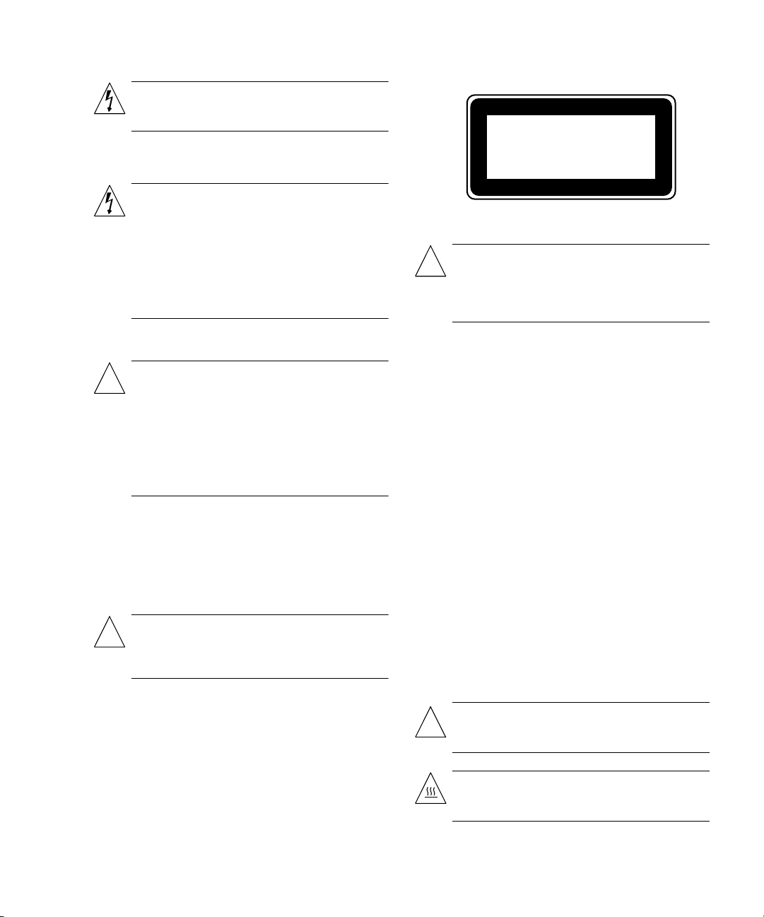
sont conformes aux normes de la classe 1 en la matière.
Class 1 Laser Product
Luokan 1 Laserlaite
Klasse 1 Laser Apparat
Laser Klasse 1
DVD-ROM
Attention – L’utilisation de contrôles, de réglages
ou de performances de procédures autre que celle
!
spécifiée dans le présent document peut
provoquer une exposition à des radiations
dangereuses.
Normativas de seguridad
El siguiente texto incluye las medidas de seguridad que
se deben seguir cuando se instale algún producto de Sun
Microsystems.
Precauciones de seguridad
Para su protección observe las siguientes medidas de
seguridad cuando manipule su equipo:
• Siga todas los avisos e instrucciones marcados en el
equipo.
• Asegúrese de que el voltaje y la frecuencia de la red
eléctrica concuerdan con las descritas en las etiquetas
de especificaciones eléctricas del equipo.
• No introduzca nunca objetos de ningún tipo a través
de los orificios del equipo. Pueden haber voltajes
peligrosos.
Los objetos extraños conductores de la electricidad
pueden producir cortocircuitos que provoquen un
incendio, descargas eléctricas o daños en el equipo.
Símbolos
En este libro aparecen los siguientes símbolos:
Precaución – Existe el riesgo de lesiones
personales y daños al equipo. Siga las
!
instrucciones.
Precaución – Superficie caliente. Evite el contacto.
Las superficies están calientes y pueden causar
daños personales si se tocan.
Appendix B Compliance Statements B-5
Page 64
Precaución – Voltaje peligroso presente. Para
reducir el riesgo de descarga y daños para la
salud siga las instrucciones.
Modificaciones en el equipo
No realice modificaciones de tipo mecánico o eléctrico en
el equipo. Sun Microsystems no se hace responsable del
cumplimiento de las normativas de seguridad en los
equipos Sun modificados.
Ubicación de un producto Sun
Precaución – Para asegurar la fiabilidad de
funcionamiento de su producto Sun y para
!
protegerlo de sobrecalentamien-tos no deben
obstruirse o taparse las rejillas del equipo. Los
productos Sun nunca deben situarse cerca de
radiadores o de fuentes de calor.
Cumplimiento de la normativa SELV
El estado de la seguridad de las conexiones de entrada/
salida cumple los requisitos de la normativa SELV.
Conexión del cable de alimentación eléctrica
Precaución – Los productos Sun están diseñados
para
trabajar en una red eléctrica monofásica con
toma de tierra. Para reducir el riesgo de descarga
eléctrica, no conecte los productos Sun a otro tipo
de sistema de alimentación eléctrica. Póngase en
contacto con el responsable de mantenimiento o
con un electricista cualificado si no está seguro
del sistema de alimentación eléctrica del que se
dispone en su edificio.
Precaución – Para eliminar toda la alimentación
de la unidad, apague todos los interruptores.
La siguiente advertencia se aplica solamente a equipos
con un interruptor de encendido que tenga una posición
"En espera":
Precaución – El interruptor de encendido de este
producto funciona exclusivamente como un
dispositivo de puesta en espera. El enchufe de la
fuente de alimentación está diseñado para ser el
elemento primario de desconexión del equipo. El
equipo debe instalarse cerca del enchufe de forma
que este último pueda ser fácil y rápidamente
accesible. No conecte el cable de alimentación
cuando se ha retirado la fuente de alimentación
del chasis del sistema.
Batería de litio
Precaución – En las placas de CPU Sun hay una
batería de litio insertada en el reloj de tiempo
!
real, tipo SGS Núm. MK48T59Y, MK48T59470PCIU, MK48TXXB-XX, MK48T18-XXXPCZ,
M48T59W-XXXPCZ, o MK48T08. Las baterías no
son elementos reemplazables por el propio
cliente. Pueden explotar si se manipulan de forma
errónea. No arroje las baterías al fuego. No las
abra o intente recargarlas.
Tapa de la unidad del sistema
Debe quitar la tapa del sistema cuando sea necesario
añadir tarjetas, memoria o dispositivos de
almacenamiento internos. Asegúrese de cerrar la tapa
superior antes de volver a encender el equipo.
Precaución – No todos los cables de alimentación
eléctrica tienen la misma capacidad. Los cables de
tipo doméstico no están provistos de protecciones
contra sobrecargas y por tanto no son apropiados
para su uso con computadores. No utilice
alargadores de tipo doméstico para conectar sus
productos Sun.
Precaución – Es peligroso hacer funcionar los
productos Sun sin la tapa superior colocada. El
!
hecho de no tener en cuenta esta precaución
puede ocasionar daños personales o perjudicar el
funcionamiento del equipo.
Aviso de cumplimiento con requisitos de
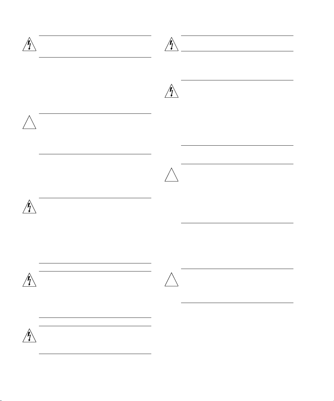
láser
Precaución – Con el producto Sun se proporciona
un cable de alimentación con toma de tierra. Para
reducir el riesgo de descargas eléctricas conéctelo
siempre a un enchufe con toma de tierra.
B-6 Sun Fire 4810/4800/3800 Systems Installation Guide • January 2002
Los productos Sun que utilizan la tecnología de láser
Page 65
cumplen con los requisitos de láser de Clase 1.
Danmark
Class 1 Laser Product
Luokan 1 Laserlaite
Klasse 1 Laser Apparat
Laser Klasse 1
DVD-ROM
Precaución – El manejo de los controles, los
ajustes o la ejecución de procedimientos distintos
!
a los aquí especificados pueden exponer al
usuario a radiaciones peligrosas.
GOST-R Certification Mark
Nordic Lithium Battery Cautions
Norge
ADVARSEL! – Litiumbatteri — Eksplosionsfare
ved fejlagtig håndtering. Udskiftning må kun ske
!
med batteri af samme fabrikat og type. Levér det
brugte batteri tilbage til leverandøren.
Suomi
VAROITUS – Paristo voi räjähtää, jos se on
virheellisesti asennettu. Vaihda paristo
!
ainoastaan laitevalmistajan suosittelemaan
tyyppiin. Hävitä käytetty paristo valmistajan
ohjeiden mukaisesti.
ADVARSEL– Litiumbatteri —
Eksplosjonsfare.
!
Ved utskifting benyttes kun batteri som anbefalt
av apparatfabrikanten. Brukt batteri returneres
apparatleverandøren.
Sverige
VARNING – Explosionsfara vid felaktigt
batteribyte. Använd samma batterityp eller en
!
ekvivalent typ som rekommenderas av
apparattillverkaren. Kassera använt batteri enligt
fabrikantens instruktion.
Appendix B Compliance Statements B-7
Page 66

B-8 Sun Fire 4810/4800/3800 Systems Installation Guide • January 2002
 Loading...