


Sun Fire™15K/12K Systems
Overview
Sun Microsystems, Inc.
www.sun.com
Part No. 806-3509-13
May 2006, Revision A
Submit comments about this document at: http://www.sun.com/hwdocs/feedback

Copyright 2006Sun Microsystems,Inc., 4150Network Circle, SantaClara, California95054, U.S.A.All rightsreserved.
Sun Microsystems,Inc. hasintellectual property rightsrelating totechnology embodiedin theproduct that is described inthis document.In
particular,and withoutlimitation, theseintellectual property rightsmay includeone ormore ofthe U.S.patents listedat
http://www.sun.com/patents andone ormore additionalpatents orpending patentapplications inthe U.S.and inother countries.
This documentand theproduct towhich itpertains are distributedunder licensesrestricting theiruse, copying,distribution, and
decompilation. Nopart ofthe productor ofthis documentmay bereproducedin anyform byany meanswithout priorwritten authorizationof
Sun andits licensors,if any.
Third-party software, includingfont technology,is copyrightedand licensedfrom Sun suppliers.
Parts ofthe productmay bederived from BerkeleyBSD systems,licensed fromthe Universityof California.UNIX isa registered trademarkin
the U.S.and inother countries,exclusively licensedthrough X/OpenCompany, Ltd.
Sun, SunMicrosystems, theSun logo,AnswerBook2, docs.sun.com,Sun Fire, SunFireplane interconnect, andSolaris aretrademarks or
registered trademarks of Sun Microsystems,Inc. inthe U.S.and inother countries.
All SPARCtrademarks areused underlicense andare trademarks or registered trademarksof SPARCInternational, Inc.in theU.S. andin other
countries. Productsbearing SPARCtrademarks are basedupon anarchitecture developed by Sun Microsystems,Inc.
The OPENLOOK andSun™ GraphicalUser Interfacewas developedby SunMicrosystems, Inc.for itsusers andlicensees. Sunacknowledges
the pioneeringefforts ofXerox in researchingand developingthe conceptof visualor graphicaluser interfacesfor thecomputer industry.Sun
holds anon-exclusive licensefrom Xerox tothe XeroxGraphical UserInterface, whichlicense alsocovers Sun’slicensees whoimplement OPEN
LOOK GUIsand otherwisecomply withSun’s writtenlicense agreements.
U.S. GovernmentRights-Commercial use.Government usersare subject to the Sun Microsystems, Inc.standard licenseagreement and
applicable provisionsof theFAR andits supplements.
DOCUMENTATION IS PROVIDED "AS IS" AND ALL EXPRESS OR IMPLIED CONDITIONS, REPRESENTATIONS AND WARRANTIES,
INCLUDING ANYIMPLIED WARRANTY OFMERCHANTABILITY, FITNESSFOR A PARTICULAR PURPOSEOR NON-INFRINGEMENT,
ARE DISCLAIMED, EXCEPT TO THE EXTENT THAT SUCH DISCLAIMERS ARE HELD TO BE LEGALLY INVALID.
Copyright 2006Sun Microsystems,Inc., 4150Network Circle, SantaClara, Californie95054, Etats-Unis.Tous droitsréservés.
Sun Microsystems,Inc. ales droits depropriété intellectuelsrelatants à la technologie incorporée dans leproduit quiest décritdans ce
document. Enparticulier,et sansla limitation,ces droits depropriété intellectuelspeuvent inclure unou plusdes brevetsaméricains énumérés
à http://www.sun.com/patents et unou lesbrevets plus supplémentairesou lesapplications debrevet enattente dansles Etats-Uniset dans
les autrespays.
Ce produitou documentest protégé parun copyrightet distribuéavec deslicences quien restreignent l’utilisation,la copie,la distribution,et la
décompilation. Aucunepartie dece produitou documentne peutêtre reproduite sousaucune forme,parquelque moyen que ce soit, sans
l’autorisation préalableet écritede Sunet deses bailleursde licence,s’il yena.
Le logicieldétenu pardes tiers,et quicomprend latechnologie relative auxpolices decaractères, estprotégépar uncopyright etlicencié pardes
fournisseurs deSun.
Des partiesde ceproduit pourront êtredérivées dessystèmes BerkeleyBSD licenciéspar l’Universitéde Californie.UNIX estune marque
déposée auxEtats-Unis etdans d’autrespays etlicenciée exclusivementpar X/OpenCompany, Ltd.
Sun, SunMicrosystems, lelogo Sun,AnswerBook2, docs.sun.com,Sun Fire, SunFireplane interconnect, etSolaris sontdes marquesde fabrique
ou desmarques déposéesde SunMicrosystems, Inc. aux Etats-Unis et dans d’autrespays.
Toutes lesmarques SPARC sont utilisées sous licence et sont des marques defabrique oudes marquesdéposées deSPARC International,Inc.
aux Etats-Uniset dansd’autres pays.Les produits protantles marques SPARC sont baséssur unearchitecturedéveloppée parSun
Microsystems, Inc.
L’interfaced’utilisation graphiqueOPEN LOOKet Sun™a étédéveloppée parSun Microsystems, Inc.pour sesutilisateurs etlicenciés. Sun
reconnaît lesefforts de pionniers de Xeroxpour larecherche et le développment du concept des interfaces d’utilisation visuelle ou graphique
pour l’industriede l’informatique.Sun détientune licensenon exclusivedo Xeroxsur l’interfaced’utilisation graphiqueXerox,cette licence
couvrant égalementles licenciéesde Sunqui mettenten placel’interface d’utilisation graphiqueOPEN LOOKet quien outrese conforment
aux licencesécrites deSun.
LA DOCUMENTATION EST FOURNIE "EN L’ÉTAT" ET TOUTES AUTRES CONDITIONS, DECLARATIONS ET GARANTIES EXPRESSES
OU TACITES SONT FORMELLEMENTEXCLUES, DANSLA MESUREAUTORISEE PARLA LOIAPPLICABLE, YCOMPRIS NOTAMMENT
TOUTE GARANTIE IMPLICITE RELATIVE A LA QUALITE MARCHANDE, A L’APTITUDE A UNE UTILISATION PARTICULIERE OU A
L’ABSENCE DE CONTREFAÇON.

Contents
Declaration of Conformity xi
Preface xiii
1. Sun Fire 15K/12K Systems Introduction 1–1
1.1 System Boards 1–2
1.1.1 CPU/Memory Boards 1–2
1.1.2 I/O Boards 1–3
1.1.3 System Controller 1–3
1.1.4 Peripherals 1–3
1.2 System Configuration 1–4
1.3 System Interconnects 1–5
1.3.1 Sun Fireplane Interconnect Architecture 1–6
1.3.2 Address Interconnect 1–7
1.3.3 Data Interconnect 1–7
1.4 Dynamic System Domains 1–8
1.5 Reliability, Availability, and Serviceability 1–9
1.5.1 Integrated Circuit Reliability 1–9
1.5.2 Interconnect Reliability 1–9
1.5.3 Fault-Tolerant Redundancy 1–10
iii

1.5.4 Reconfiguration After Failure 1–10
1.5.5 Serviceability 1–10
2. Dynamic System Domains 2–1
2.1 Domain Configurability 2–1
2.2 Domain Protection 2–3
2.3 Domain Fault Isolation 2–3
3. Reliability, Availability, and Serviceability 3–1
3.1 SPARC CPU Error Protection 3–1
3.2 System Interconnect Error Protection 3–3
3.2.1 Address Interconnect Error Protection 3–3
3.2.2 Data Interconnect Error Protection 3–3
3.2.3 Data Interconnect Error Isolation 3–4
3.2.4 Console Bus Error Protection 3–4
3.3 Redundant Components 3–6
3.3.1 Redundant CPU/Memory Boards 3–6
3.3.2 Redundant I/O Boards 3–6
3.3.3 Redundant PCI Cards 3–7
3.3.4 Redundant System Control Boards 3–7
3.3.5 Redundant System Clocks 3–7
3.3.6 Redundant Power 3–7
3.3.7 Redundant Fans 3–8
3.4 Reconfigurable Sun Fireplane Interconnect 3–8
3.5 Automatic System Recovery 3–9
3.5.1 Built-In Self-Test 3–9
3.5.2 Power-On Self-Test 3–9
3.6 System Controller 3–9
3.6.1 Console Bus 3–10
iv Sun Fire™ 15K/12K Systems • May 2006

3.6.2 Environmental Monitoring 3–10
3.7 Concurrent Serviceability 3–11
3.7.1 Dynamic Reconfiguration of System Boards 3–11
3.7.2 System Controller Board Set Removal and Replacement 3–13
3.7.3 Bulk Power Supply Removal and Replacement 3–13
3.7.4 Fan Tray Removal and Replacement 3–13
3.7.5 Remote Service 3–13
4. System Interconnect 4–1
4.1 Data-Transfer Interconnect Levels 4–3
4.2 Address Interconnect 4–5
4.3 Data Interconnect 4–7
4.4 Interconnect Bandwidth 4–9
4.5 Interconnect Latency 4–10
5. System Components 5–1
5.1 Cabinets 5–2
5.1.1 System Power 5–4
5.1.2 System Cooling 5–4
5.2 Centerplanes 5–5
5.2.1 Sun Fireplane Interconnect 5–7
5.3 System Boards 5–7
5.3.1 System Board Set 5–8
5.3.1.1 Expander Board 5–8
5.3.1.2 CPU/Memory Board 5–8
5.3.1.3 Example of System Board Set 5–9
5.3.1.4 PCI Assembly (hsPCI-X/hsPCI+) 5–9
5.3.1.5 MaxCPU Board 5–9
5.3.2 Controller Board Set 5–13
Contents v

Glossary Glossary–1
Index Index–1
vi Sun Fire™ 15K/12K Systems • May 2006

Figures
FIGURE 1-1 Sun Fire 15K/12K Systems 1–2
FIGURE 1-2 Sun Fireplane Interconnects 1–7
FIGURE 2-1 Example of Domain Configuration With Some Split Board Sets 2–2
FIGURE 3-1 CPU Error Detection and Correction 3–2
FIGURE 3-2 Interconnect ECC and Parity Checking 3–6
FIGURE 4-1 Sun Fire 15K/12K Systems Interconnect 4–2
FIGURE 4-2 Sun Fire 15K/12K Systems Data—Transfer Interconnect Levels 4–3
FIGURE 4-3 Address Interconnect Levels 4–6
FIGURE 4-4 Data Interconnect Levels 4–8
FIGURE 5-1 Sun Fire 15K/12K Systems Major Components 5–2
FIGURE 5-2 Sun Fire 15K/12K Systems Cabinet—Front View 5–3
FIGURE 5-3 Sun Fireplane interconnect and Other Components 5–7
FIGURE 5-4 Board Set Block Diagram 5–11
FIGURE 5-5 System Board Set Layout 5–13
FIGURE 5-6 System Controller Board Layout 5–14
vii

viii Sun Fire™ 15K/12K Systems • May 2006

Tables
TABLE 1-1 Sun Fire 15K/12K System Maximum Configuration 1–4
TABLE 1-2 Sun Fire 15K/12K Systems Interconnect Specifications 1–5
TABLE 4-1 Interconnect Levels 4–4
TABLE 4-2 Peak Interconnect Bandwidth 4–9
TABLE 4-3 Pin-to-Pin Latency for Data in Memory 4–10
TABLE 4-4 Pin-to-Pin Latency for Data in Cache 4–11
ix

x Sun Fire™ 15K/12K Systems • May 2006

Declaration of Conformity
Compliance Model Number: 2080
Product Name: Sun Fire 15K/12K System
EMC
European Union
This equipment complies with the following requirements of the EMC Directive 89/336/EEC:
EN55022:1995/CISPR22:1997 Class A
EN55024:1998 EN61000-4-2 4 kV (Direct), 8 kV (Air)
EN61000-4-3 3 V/m
EN61000-4-4 1.0 kV Power Lines, 0.5 kV Signal Lines
EN61000-4-5 1 kV Line-Line, 2 kV Line-Gnd Power Lines
EN61000-4-6 3 V
EN61000-4-8 3 A/m
EN61000-4-11 Pass
EN61000-3-2:1995 Pass
EN61000-3-3:1995 Pass
Safety
This equipment complies with the following requirements of the Low Voltage Directive 73/23/EEC:
EC Type Examination Certificates:
EN60950:1992, 2nd Edition, Amendments 1,2,3,4,11 TÜV Product Service Certificate No.
IEC 950:1991, 2nd Edition, Amendments 1,2,3,4
Evaluated to all CB Countries CB Scheme Certificate No. CB 01 07 17641 014
Z1A 01 07 17641 013
Supplementary Information
This product was tested and complies with all the requirements for the CE Mark.
Dennis P. Symanski DATE
Manager, Compliance Engineering
Sun Microsystems, Inc.
4150 Network Circle
Santa Clara, CA 95054, USA
Tel: 650-786-3255
Fax: 650-786-3723
Peter Arkless DATE
Quality Manager
Sun Microsystems Scotland, Limited
Springfield, Linlithgow
West Lothian, EH49 7LR
Scotland, United Kingdom
Tel: 0506-670000
Fax: 0506 760011
xi

xii Sun Fire™ 15K/12K Systems • May 2006

Preface
This document introduces the Sun Fire™ 15K/12K systems and describes the
cabinet, the system, the configuration, the dynamic system domain configurability,
the system boards, and the reliability, availability, and serviceability features.
How This Book Is Organized
Chapter 1 describes the systems and boards, the maximum configurations, and the
interconnect architecture.
Chapter 2 describes the configurability, inter-domain networking, domain
protection, and domain fault isolation.
Chapter 3 defines system error protection, describes the redundant components and
system recovery, discusses the system controller technology, and explains the
concurrent serviceability features of the systems.
Chapter 4 describes the heart of the system, which is the Sun™ Fireplane
interconnect assembly.
Chapter 5 describes the components within the systems.
xiii

Related Documentation
TABLE P-1 Related Documentation
Application Title
Service Sun Fire 15K/12K Systems Read Me First
Service Sun Fire 15K/12K Systems Getting Started
Service Sun Fire 15K/12K Systems Unpacking Guide
Service Sun Fire 15K/12K Systems Site Planning Guide
Service Sun Fire 15K/12K Systems Hardware Installation and De-Installation Guide
Service Sun Fire 15K/12K Systems Service Manual
Service Sun Fire 15K/12K Systems Service Reference I–Nomenclature
Service Sun Fire 15K/12K Systems Service Reference II–Component Numbering
Service Sun Fire 15K/12K Systems Carrier Plate Configurations
Accessing Sun Documentation
You can view, print, or purchase a broad selection of Sun documentation, including
localized versions, at:
http://www.sun.com/documentation
Contacting Sun Technical Support
If you have technical questions about this product that are not answered in this
document, go to:
http://www.sun.com/service/contacting
xiv Sun Fire™ 15K/12K Systems • May 2006

Sun Welcomes Your Comments
Sun is interested in improving its documentation and welcomes your comments and
suggestions. You can submit your comments by going to:
http://www.sun.com/hwdocs/feedback
Please include the title and part number of your document with your feedback:
Sun Fire™ 15K/12K Systems, part number 806-3509-13
United States Export Control Laws
Notice
Products covered by and information contained in this service manual are controlled
by U.S. Export Control laws and might be subject to the export or import laws in
other countries. Nuclear, missile, chemical biological weapons, or nuclear maritime
end uses or end users, whether direct or indirect, are strictly prohibited. Export or
re-export to countries subject to U.S. embargo or to entities identified on U.S. export
exclusion lists, including but not limited to the denied persons and specially
designated nationals lists, is strictly prohibited. Use of any spare or replacement
CPUs is limited to repair or one-for-one replacement of CPUs in products exported
in compliance with U.S. export laws. Use of CPUs as product upgrades unless
authorized by the U.S. Government is strictly prohibited.
xv

xvi Sun Fire™ 15K/12K Systems • May 2006

CHAPTER
1
Sun Fire 15K/12K Systems Introduction
This chapter provides the following introductory information for the Sun Fire
15K/12K systems:
■ Section 1.1, “System Boards” on page 1-2
■ Section 1.2, “System Configuration” on page 1-4
■ Section 1.3, “System Interconnects” on page 1-5
■ Section 1.4, “Dynamic System Domains” on page 1-8
■ Section 1.5, “Reliability, Availability, and Serviceability” on page 1-9
The Sun Fire 15K/12K systems use the latest UltraSPARC™ III Cu CPU and the Sun
Fireplane interconnect architecture running the binary-compatible Solaris™ 8 UNIX
operating environment (FIGURE 1-1). The Sun Fireplane interconnect has faster CPUs.
The industry-leading dynamic system domain and reliability, availability, and
serviceability (RAS) capabilities have been applied and use the active-centerplane
technology.
1-1
®
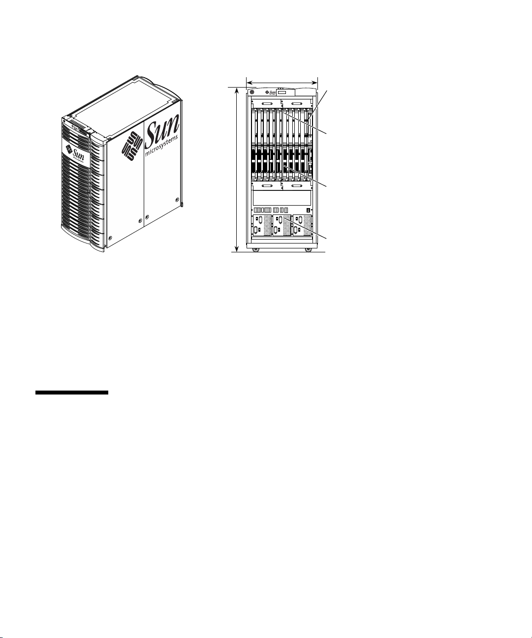
33.3 in. (84.6 cm)
System Control boards
(front and rear)
CPU/Memory boards
(9 in front and 9 in rear
of the Sun Fire 15K system)
75.5 in.
(191.8 cm)
18 CPU/Memory boards and 18 I/O boards in the Sun Fire 15K system
9 CPU/Memory boards and 9 I/O boards in the Sun Fire 12K system
(with 9 CPU and I/O filler panels in the rear of the system)
FIGURE 1-1 Sun Fire 15K/12K Systems
(9 in front and 9 filler panels
in rear of the Sun Fire 12K system)
I/O boards
(9 in from and 9 in rear
of the Sun Fire 15K system)
(9 in front and 9 filler panels
in rear of the Sun Fire 12K system)
Bulk power supply (3 in front, 3 in rear)
The Sun Fire 15K/12K systems are essentially the same. The Sun Fire 15K system has
the capacity for 18 CPU/Memory boards and 18 I/O boards. The Sun Fire 12K
system has the capacity for nine CPU/Memory boards and nine I/O boards. Each
system contains two System Control boards (one main and one spare).
1.1 System Boards
1.1.1 CPU/Memory Boards
The CPU/Memory board holds four CPUs. Each CPU has an associated memory
subsystem of eight DIMMs, so memory bandwidth and capacity are both scaled up
as CPUs are added. The memory capacity of the board is 32 Gbytes using a 1-Gbyte
DIMM. The maximum memory bandwidth inside a board is 9.6 Gbytes per second.
The CPU/Memory board has a 4.8 Gbyte per second connection to the rest of the
system.
1-2 Sun Fire™ 15K/12K Systems • May 2006

1.1.2 I/O Boards
The Sun Fire 15K/12K hot-swap PCI assembly architecture (hsPCI-X/hsPCI+) has
two I/O controllers. Each controller provides one 33-MHz peripheral component
interconnect (PCI) bus and three 33/66/90 MHz PCI buses for a total of four on each
I/O assembly. Therefore, each I/O assembly has four hot-swap component PCI slots.
A Sun Fire I/O assembly has a 2.4 Gbyte/sec connection to the rest of the system.
1.1.3 System Controller
The system controller is the heart of the Sun Fire 15K/12K systems availability and
serviceability technology. It configures the system, coordinates the boot process, sets
up the dynamic system domains, monitors the system environmental sensors, and
handles error detection, diagnosis, and recovery. Two System Control boards are
configured into the system to provide redundancy and automatic failover in the
event that one board fails.
1.1.4 Peripherals
The Sun Fire 15K/12K systems cabinet does not have room for peripherals, with the
exception of the system controller peripherals (DVD-ROM, digital audio tape (DAT)
drive, and hard drive). However, more peripheral devices can be configured in
additional peripheral expansion racks.
Chapter 1 1-3

1.2 System Configuration
TABLE 1-1 summarizes the maximum configuration of the Sun Fire 15K/12K systems.
TABLE 1-1 Sun Fire 15K/12K System Maximum Configuration
Component 15K Configuration 12K Configuration
CPU/Memory boards 18 9
CPUs 72 36
Number of DIMMs 576 288
Memory capacity (with 1-Gbyte DIMMs) 576 GB 288 GB
Sun Fireplane interconnect Active Active
Repeater boards NA NA
Expander boards 18 9
Domains 18 9
I/O boards (assemblies) 18 9
PCI assembly types hsPCI+ hsPCI+
PCI assembly types hsPCI-X hsPCI-X
PCI slots per assembly 4 4
Maximum PCI slots 72 36
Bulk power supplies 6 6
Power requirements 24 kW 24 kW
System Control boards 2 2
Redundant cooling Yes Yes
Redundant AC input Yes Yes
Enclosure Sun Fire 15K/12K
Systems cabinet
Room in enclosure for peripherals No No
Sun Fire 15K/12K
Systems cabinet
1-4 Sun Fire™ 15K/12K Systems • May 2006

1.3 System Interconnects
TABLE 1-2 summarizes the interconnect capacities of the Sun Fire 15K/12K systems.
TABLE 1-2 Sun Fire 15K/12K Systems Interconnect Specifications
Interconnect Specification
System clock 150 MHz
Coherency protocol Snooping on each board set,
System address interconnect 18 snoopy buses,
CPU/Memory board internal bisection
bandwidth
CPU/Memory board
off-board data port
I/O board
off-board data port
System data interconnect 18 3x3 board set crossbars,
System bisection bandwidth 43 Gbytes/sec
Average lmbench (back-to-back-load) latency
assumes random accesses
directory across a centerplane
18x18 global address crossbar,
18x18 global response crossbar,
4.8 Gbytes/sec
4.8 Gbytes/sec
2.4 Gbytes/sec
18 x 18 global crossbar
326 ns
Note – The definition of snooping, as defined in the PCI System Architecture, Third
Edition, Appendix A: Glossary, 1995, by MindShare, Inc., (ISBN 0-201-40993-3):
Snooping – When a memory access is performed by an agent other than the
cache controller, the cache controller must snoop the transaction to
determine if the current master is accessing information that is also
resident within the cache. If a snoop hit occurs, the cache controller
must take an appropriate action to ensure the continued consistency
of its cached information.
Chapter 1 1-5
1.3.1 Sun Fireplane Interconnect Architecture
The Sun Fire 15K/12K systems use the Sun Fireplane interconnect systeminterconnect architecture that is the coherent shared-memory protocol used by the
UltraSPARC III Cu CPU generation. This is the fourth generation of shared-memory
interconnect. Sun Microsystems uses an improved system interconnect with each
new CPU generation to keep system performance scaling with CPU performance.
The Sun Fireplane interconnect architecture is an evolutionary improvement over
the previous generation Ultra Port Architecture (UPA). The system clock rate is
increased by 50% from 100 MHz to 150 MHz. The snoops per clocks are doubled
from one half to one. Taken together, this triples the snooping bandwidth to 150
million addresses per second.
The Sun Fireplane interconnect architecture also adds a new layer of point-to-point
directory-coherency protocol. This protocol is used in systems that require more
bandwidth than a single snoopy bus can provide. This facility enables coherency to
be maintained between multiple snoopy buses.
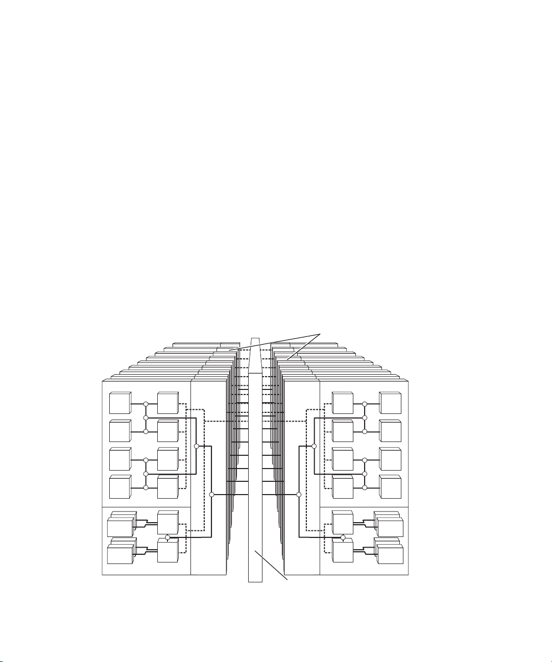
FIGURE 1-2 shows the Sun Fireplane interconnect architecture of the Sun Fire 15K
system. The board diagrams show the actual on-board connectivity but omit the
switch and controller chips for clarity.
18 Sun Fire 15K system
expander boards
M
M
M
M
PCI
PCI
FIGURE 1-2 Sun Fireplane Interconnects
1-6 Sun Fire™ 15K/12K Systems • May 2006
C
C
C
C
I
I
C
C
C
C
I
I
18 x 18 address and response crossbars
M
M
M
M
Diagram shown:
Sun Fire 15K
system
PCI
PCI

The Sun Fire 15K/12K systems use an expander board to implement a 3x3 switch
between a CPU/Memory board, an I/O board, and the Sun Fireplane interconnect
port. The Sun Fire 15K/12K systems have three 18x18 crossbars on its Sun Fireplane
interconnect for addresses, responses, and data so that address traffic does not
interfere with data traffic. The peak Sun Fire 15K/12K systems Sun Fireplane
interconnect bandwidth is 43 Gbytes per second.
1.3.2 Address Interconnect
The dashed lines in FIGURE 1-2 are the snoopy address buses. A snoop can occur at
every system clock. In the Sun Fire 15K/12K systems, there is a separate snoopy
address bus on each board set. A board set is the combination of a CPU/Memory
board, an I/O board, and an expander board. Coherency is maintained between
board sets by using the point-to-point (directory) portion of the coherency protocol.
1.3.3 Data Interconnect
The solid lines in FIGURE 1-2 represent the data paths. The small circles at the
intersections of these lines indicate three-port switches. The CPU/Memory board
has three levels of 3x3 switches between a CPU or memory unit and the off-board
port. The off-board bandwidth of a CPU/Memory board is 4.8 Gbytes per second.
The bandwidth of an I/O board is 2.4 Gbytes per second.
Chapter 1 1-7

1.4 Dynamic System Domains
Each domain in the Sun Fire 15K/12K systems include one or more
CPU/Memory boards and one or more I/O boards. Each domain runs its own
instance of the Solaris operating environment and has its own peripherals and
network connections. Domains can be reconfigured without interrupting the
operation of other domains. Domains can be used for:
■ Testing new applications
■ Making operating system updates
■ Supporting various departments
■ Removing and reinstalling boards for repair or upgrade
As an example, the Sun Fire 15K system is divided into three domains. Here is one
example of partitioning a fully populated system into three domains to handle three
types of functions:
■ Domain 1 is set up to run online transaction processing (OLTP). It is a 32-CPU
domain containing eight boards of four CPUs each.
■ Domain 2 is set up to run decision support software (DSS). It is also a 32-CPU
domain containing eight boards of four CPUs each.
■ Domain 3 is set up as a domain for developers. It is a two-board domain, each
board with four CPUs.
Boards can be automatically migrated between domains as the load change
demands.
The Sun Fire 15K system can have up to 18 domains. The Sun Fire 12K system can
have up to 9 domains. Domains are isolated from each other by the interconnect
application-specific integrated circuits (ASICs).
1-8 Sun Fire™ 15K/12K Systems • May 2006

1.5 Reliability, Availability, and Serviceability
Reliability, availability, and serviceability (RAS) are critical requirements of
customers who deploy business-critical applications. The Sun Fire 15K/12K systems
build upon the industry-leading RAS capabilities. The sections that follow describe
some of the major features that improve RAS.
1.5.1 Integrated Circuit Reliability
■ Start-up diagnostics. All major Sun Fire 15K/12K systems ASICs do a built-in
self-test (BIST) on power-on. This applies random patterns at a system clock rate
to provide a high-fault coverage of combinatorial logic. The power-on self-test
(POST) is controlled from the system controller, and first tests each logic block in
isolation. Then the POST continues testing using more and more of the system.
Failing components are electrically isolated from the Sun Fireplane interconnect.
The result is that the system is booted only with logic blocks that have passed this
self-test and that should operate without error.
■ Internal SRAM protection inside the UltraSPARC III Cu CPU. With higher-
density CPUs and lower-core voltages, SRAM cells have become more vulnerable
to bit flips from cosmic-ray disturbances. Single-bit errors for the majority of the
internal SRAMs are detected and are recoverable.
■ External SRAM protection. All external SRAMs are protected by error-correcting
codes (ECC). This includes the external cache data of the CPU and the coherency
directory cache of the Sun Fire 15K/12K systems.
1.5.2 Interconnect Reliability
■ Address interconnect protection. The Sun Fire 15K/12K systems address buses
and control signals are parity protected to detect single-bit errors. In addition, the
address and response crossbars on the Sun Fireplane interconnect have ECC
protection to correct single-bit errors and detect double-bit errors.
■ Data interconnect protection. The entire system data path is protected by ECC,
which corrects single-bit errors and detects double-bit errors before they can
cause data corruption. ECC is generated by a CPU or I/O controller when it
initiates a write command. The extra bits are carried throughout the interconnect
to the destination. The memory subsystem does not check or correct errors, but
only provides the extra storage bits. When data is read out of memory, it is
checked and, if necessary, corrected by the receiving CPU or I/O controller.
Chapter 1 1-9

To help isolate failures, parity is also checked as data is passed from chip to chip.
The data switch ASICs also check ECC. The ECC patterns use detect-complete
DRAM chip failures but cannot correct them.
1.5.3 Fault-Tolerant Redundancy
A failure in these subsystems does not cause any loss of availability.
■ N+1 redundancy. The AC power inputs, the bulk-power supplies, and the cooling
fans are all fault tolerant through N+1 redundancy. If one of these subunits fails,
the remainder of the components can continue system operation without
interruption.
■ Failover while running. The System Control boards are configured in pairs. One
is active, and the other is a hot-spare. In the event of a failure of the system
controller CPU or of the clock generation logic, control is switched from the failed
board to the other board without system interruption.
1.5.4 Reconfiguration After Failure
■ Automatic system recovery. A suitably configured system always reboots after a
failure. The system controller locates the fault; reconfigures the system excluding
the failed CPU, memory, or interconnect component; and reboots the operating
system.
■ Interconnect reconfiguration after failure. After a system interconnect failure
occurs, the system restarts with the bad interconnect components isolated and
with half the system bandwidth still available. The three crossbars can be
separately reconfigured between full and degraded mode on a domain-bydomain basis.
1.5.5 Serviceability
■ System controller. The System Control board is the heart of the RAS technology.
The SC CPU board is an off-the-shelf SPARCengine CP1500 6U cPCI board with
an UltraSPARC IIi embedded system. This board runs Solaris Software and
System Management Software. The system controller has access by means of
JTAG (joint test action group) to registers in each significant chip in the machine,
and continuously monitors the state of the machine. If a problem is detected, the
system controller attempts to determine what hardware has malfunctioned and
then takes steps to prevent that hardware from being accessed until it has been
replaced.
1-10 Sun Fire™ 15K/12K Systems • May 2006

■ Console bus. The console bus is a secondary bus that enables the system
controller to access the inner workings of the machine without having to rely on
the integrity of the system address and data buses. This enables the system
controller to operate even when there is a fault that prevents the system operation
from continuing. It is protected by parity.
■ Environmental monitoring. The system controller monitors the cabinet
environment for key measures of system stability such as temperature, fan
operation, and power supply performance.
■ Concurrent serviceability. The fans, the bulk power supplies, and the system
boards are all hot-swap components. They can be removed and replaced in a
running system.
■ Dynamic system domains. Dynamic system domains enable a repaired or
upgraded board to be added or removed from a running domain.
Chapter 1 1-11

1-12 Sun Fire™ 15K/12K Systems • May 2006

CHAPTER
2
Dynamic System Domains
The Sun Fire 15K/12K systems contain dynamic domains. These domains are
described in the following sections.
■ Section 2.1, “Domain Configurability” on page 2-1
■ Section 2.2, “Domain Protection” on page 2-3
■ Section 2.3, “Domain Fault Isolation” on page 2-3
The Sun Fire 15K system can be dynamically subdivided into as many as 18 dynamic
system domains. The Sun Fire 12K system can be subdivided into as many as 9
dynamic system domains. Each domain has a separate boot disk (to execute a
specific instance of the Solaris operating environment) as well as separate disk
storage, network interfaces, and I/O interfaces. CPU boards and I/O boards can be
separately added and removed from running domains.
Domains are used for server consolidation to run separate parts of a solution, such
as an application server, a web server, and a database server. The domains are
hardware-protected from hardware or software faults in other domains.
2.1 Domain Configurability
Each of the system boards (slot 0 and slot 1 boards) can be independently added to,
or removed from, a running domain. This enables CPU and memory resources to be
moved from one domain to another without disturbing the disk storage and
network connections. In the Sun Fire 15K system, each domain must have an I/O
board; therefore, there is a maximum of 18 domains. In the Sun Fire 12K system,
each domain must have an I/O board; therefore, there is a maximum of 9 domains.
2-1

When the two system boards in a board set are in separate domains, this board set is
termed a split expander. The expander board keeps the transactions separate for each
system board.
FIGURE 2-1 shows an example of configuration with some of the board
sets split between the two domains. No physical proximity is needed for boards in a
domain.
Since split-expander hardware is shared between two domains, this board set failure
will bring down both domains. For example, if a fully configured system is divided
into two nine-board set domains, the impact of all split, versus all unsplit, expanders
is on the order of 5% higher MTBF (mean time between failure). Also, memory
accesses that go through a split expander take two system clocks (13 ns) longer. If all
expanders were split, the load-use latency for accesses to other board sets would
increase about 6%.
CPU/
Memory
I/O
CPU/
Memory
I/O
CPU/
Memory
I/O
Domain
A
FIGURE 2-1 Example of Domain Configuration With Some Split Board Sets
Expander ExpanderExpander
Sun Fireplane interconnect
Domain
B
Diagram shown for the Sun Fire 15K system
CPU/
Memory
I/O
CPU/
Memory
Expander ExpanderExpander
I/O
CPU/
Memory
I/O
Split Expander
Expander
2-2 Sun Fire™ 15K/12K Systems • May 2006

2.2 Domain Protection
Primary domain protection is accomplished in the address extender queue (AXQ)
ASICs by checking each transaction for domain validity when a transaction is first
detected. In the Sun Fire 15K system, the system data interface (SDI) chips can also
screen data transfer requests for valid destinations (to as many as 36 system boards).
In addition, each Sun Fireplane interconnect arbiter (data, address, response) screens
requests to as many as 18 expanders. In the Sun Fire 12K system, the SDI chips can
screen data transfer requests for valid destinations (to as many as 18 system boards).
Each Sun Fireplane interconnect arbiter (data, address, response) screens requests to
as many as 9 expanders.This is a double check on the other domain protection
mechanisms, which are in the AXQ and the SDI chips.
If a transgression error is detected in the AXQ, the AXQ treats the error operation
like a request to nonexistent memory. It reissues the request without asserting a
mapped coherency protocol signal, causing a Solaris operating environment switch
execution from one process to another. A transgression error in the Sun Fireplane
interconnect causes a domainstop of the transgressing domains because this error
must indicate a failure of the primary protection mechanism.
2.3 Domain Fault Isolation
Domains are protected against software or hardware faults in other domains. If
there is a fault in the processor or memory hardware that is assigned to a particular
domain, only that one domain will be affected. If there is a fault in hardware that is
shared between multiple domains, only those domains that share the hardware are
affected.
As an example of hardware shared between two domains, consider a system which
is configured to have a CPU/Memory board in one domain and its associated I/O
board in another domain. The logic on a split expander board is shared between
those two domains. A fault in a split expander or its control wiring to the Sun
Fireplane interconnect causes a failure only in those two domains. A fault in globally
shared hardware, such as the system clock generator or Sun Fireplane interconnect
chips, causes a failure in all domains.
Fatal errors, such as a parity error in control wiring or a faulty ASIC, causes a
domainstop. The steering signals from the expander boards to the arbiter chips of the
Sun Fireplane interconnect are parity protected. If there is a parity error, the multiple
copies of the Sun Fireplane interconnect arbiter could get out of sync. Therefore, this
type of parity error causes an immediate domainstop of the domain.
Chapter 2 2-3

Nonfatal errors or correctable single-bit errors in packets sent through the Sun
Fireplane interconnect causes a recordstop. A recordstop freezes the history buffers in
the ASICs, enabling failure information to be scanned out through JTAG while the
domain continues to run.
For a split-expander transaction (expander with board 0 and board 1 in different
domains), it is necessary to keep the arbiters in sync so that the error cannot
propagate to multiple domains. In this type of transaction, two extra cycles of
latency are introduced so that a steering parity error can be detected by all arbiters
before one arbiter processes its own correct version of the steering. Configure your
system with a minimum of split expanders to improve system performance.
The steering signals within the Sun Fireplane interconnect, from the data arbiter
ASICs to the data MUX ASICs, are parity protected. It is not possible for the data
MUX chips to cross-check for errors before processing on the steering. Therefore, a
parity error on these localized wires could cause a domainstop in any or all domains.
2-4 Sun Fire™ 15K/12K Systems • May 2006

CHAPTER
3
Reliability, Availability, and Serviceability
Reliability, availability, and serviceability (RAS) assess and measure system ability to
operate continuously and to minimize service times. The reliability of a system
reduces failures and ensures data integrity. The serviceability group provides short
service cycles when component upgrades are necessary or failures occur. When high
reliability, to avoid failures, and quick serviceability, to recover rapidly from failures,
are combined, the result is high availability. The availability of a system defines
continuous accessibility to the functions and applications supported by the system.
The supported functions and applications are described in the following section:
■ Section 3.1, “SPARC CPU Error Protection” on page 3-1
■ Section 3.2, “System Interconnect Error Protection” on page 3-3
■ Section 3.3, “Redundant Components” on page 3-6
■ Section 3.4, “Reconfigurable Sun Fireplane Interconnect” on page 3-8
■ Section 3.5, “Automatic System Recovery” on page 3-9
■ Section 3.6, “System Controller” on page 3-9
■ Section 3.7, “Concurrent Serviceability” on page 3-11
3.1 SPARC CPU Error Protection
The CPU has error correction code (ECC) protection on its external cache SRAM and
parity protection on the major internal SRAM structures, as shown in
letters P and E in the block diagram denote parity generate and check; and ECC
generate, check, and correct by the receiving unit, respectively. A parity error on an
internal cache structure is corrected by software, ensuring correct operation after the
fault.
FIGURE 3-1. The
3-1

Instruction cache
Data cache
Data
(32 KB)
P
Physical
tags
Snoop
tags
P
P
Data
(64 KB)
P
Prefetch cache
Block load buffer Merge unit
External
cache
control
tags (90 KB)
Writeback buffer
System interface and memory control
P
System
address
Dual CPU data switch
bus
Physical
tags
P
Write cache
E cache
E
P
P
Snoop
tags
P
E
CPU chip
External
cache
E
SRAM
Memory
SDRAM
DIMMs
P
= Parity generate and check
C
= ECC check
FIGURE 3-1 CPU Error Detection and Correction
3-2 Sun Fire™ 15K/12K Systems • May 2006
E
= ECC generate,
check, and correct
System data path
Address path
data path

The external cache data resides on eight high-speed (4 ns) SRAMs. A single-bit error
correcting a double-bit error detecting code protects the 64-byte-wide cache lines.
Errors during data-cache or instruction-cache fills are recovered by software flushing
and invalidation. Errors during system data transactions are corrected by hardware.
The Sun Fire 15K/12K systems address bus connection between the CPU and the
address repeater are protected by parity.
The CPU generates both parity and ECC for all outgoing data blocks. The parity is
checked by the receiving dual-CPU data switch. The ECC is checked by all data
switch units in the path of a transfer. ECC is checked and corrected by the CPU
when it receives a data block.
3.2 System Interconnect Error Protection
FIGURE 3-2 shows the protection methods at various points in the address and data
interconnect. The letters P, E, and C in the block diagram denote parity generate and
check; ECC check; and ECC generate, check, and correct by the receiving unit,
respectively. Dashed lines denote the address interconnect, and solid lines denote the
data interconnect.
3.2.1 Address Interconnect Error Protection
The Sun Fireplane interconnect address bus has three parity-error bits. In addition to
the bus-level protection, the address and response crossbars on the Sun Fire
15K/12K systems Sun Fireplane interconnect have ECC protection for address
transactions across the Sun Fireplane interconnect. The ECC corrects single-bit
address errors and detects double-bit errors. An address parity or uncorrectable ECC
error stops execution in the affected dynamic system domain.
3.2.2 Data Interconnect Error Protection
All data interconnect transactions move a 64-byte-wide data block. System devices
generate ECC when they source data, either for a write from the device or in
response to a read of the device. They check ECC and correct single-bit errors when
they receive data. Data is thus protected against both memory and data path errors
from end to end.
Chapter 3 3-3

3.2.3 Data Interconnect Error Isolation
If system devices checked only ECC when they received data, it would be difficult to
diagnose the cause of an error. If a device generates bad ECC on a write to memory,
the error can be detected by some other devices, but the cause of the error is difficult
to isolate. There are two additional checks to help isolate the cause of the errors:
■ Individual point-to-point data links are covered by parity. This is denoted by a
P in
FIGURE 3-2.
■ ECC is checked as it enters or leaves each system device by the level 1 data
switch. This is denoted by an E in
The ECC checks that are performed by the data switch can identify the source of
ECC errors in most cases. A particularly hard case for ECC errors occurs when a
device writes bad ECC into memory. These errors are detected much later by other
devices reading these locations. Since the bad device writer might have written bad
ECC to many locations and these might be read by many devices, the errors appear
to be in many memory locations while the real error might be a single bad device
writer.
Because the data switch ASICs check the ECC for all data entering or leaving each
device from other devices, the original source of errors can be isolated. For example,
a bad device writer that writes bad ECC to a memory on a different board produces
ECC errors that are detected in two data switches. The direction and transaction tag
information can identify which CPU pair was the source of the error and which
device is the target of a bad ECC device writer.
FIGURE 3-2.
If the bad device writer writes bad ECC to its local memory, then the data does not
pass through a data switch. Therefore, the bad device writer is not detected until the
data with the bad ECC is read by either the same CPU or another device. In either
case, the cause of the ECC error can be isolated to the pair of CPUs that share the
dual CPU data switch (DCDS). If the data is read by the same CPU, the fact that the
data switch on that board never detected an error indicates that the data was
corrupted by the local CPU or the DCDS. If the data is read by a different CPU pair,
then the data passes through a data switch and the ECC error is detected as
originating from a particular DCDS or the associated CPUs.
3.2.4 Console Bus Error Protection
The console bus is a secondary bus that enables access by the system controller to
the inner workings of the machine without having to rely on the integrity of the
primary data and address buses. This enables the system controller to operate even
when there is a fault preventing the continuation of the main operation. This console
bus action is common to all domains and is parity protected.
3-4 Sun Fire™ 15K/12K Systems • May 2006

18 x 18
address
crossbar
18 x 18
response
crossbar
P
P
CPU
and
Ecache
E
P
P
Memory
Dual CPU
data switch
P
E
Address
P
P
repeater
P
P
P
System
address
controller
E
P
E
P
CPU/
Memory
P
CPU
and
Ecache
Memory
board
CPU
P
and
Ecache
E
Memory
Sun
Fireplane
P
Expander
board
P
System
interface
18 x 18
data
crossbar
P
= Parity generate and check
= ECC check
C
FIGURE 3-2 Interconnect ECC and Parity Checking
data
P
P
E
and
PCI
Dual CPU
data switch
Memory
PCI card
PCI card
P
PC
Data
P
switch
P
PC
P
CPU
Ecache
P
Address
repeater
P
P
P
controller
E
PCI I/O board
PC
P
E
Data
P
switch
PC
= ECC generate,
check, and correct
P
PCI
controller
E
Address path
data path
PCI card
PCI card
Chapter 3 3-5

3.3 Redundant Components
System availability is greatly enhanced by the ability to configure redundant
components. All hot-swap components in the system can be configured redundantly,
if the customer desires. Each system board is capable of independent operation. The
Sun Fire 15K/12K systems are built with multiple system boards and are inherently
capable of operating with a subset of the configured boards.
Redundant system components include:
■ CPU/Memory boards
■ I/O boards
■ PCI cards
■ System Control boards
■ System clock sources
■ Bulk power supplies
■ Fan trays
3.3.1 Redundant CPU/Memory Boards
A Sun Fire 15K system can configure up to 18 CPU/Memory boards. A Sun Fire 12K
system can configure up to 9 CPU/Memory boards. Each board contains up to four
CPUs and their associated memory banks. Each CPU/Memory board is capable of
independent operation and can be hot-swapped out of a running system and moved
between system domains. The system is inherently capable of operating with a
subset of the configured boards.
3.3.2 Redundant I/O Boards
A Sun Fire 15K system can configure up to 18 I/O assemblies (hsPCI-X/hsPCI+). A
Sun Fire 12K system can configure up to 9 I/O assemblies. Each assembly supports
up to four PCI cards. The I/O assemblies can be hot-swapped out of running
systems and moved between system domains.
3-6 Sun Fire™ 15K/12K Systems • May 2006

3.3.3 Redundant PCI Cards
You can mount a standard PCI card on the Sun Fire 15K/12K systems PCI I/O board
by using a special cassette that enables the cards to be changed using the hot-swapreplacement procedures. You can configure systems with multiple connections to
the peripheral devices, enabling redundant controllers and channels. Software
maintains the multiple paths and can switch to an alternate path if the primary fails.
3.3.4 Redundant System Control Boards
The Sun Fire 15K/12K systems contain two System Control boards. The system
controller software running in each embedded CPU checks the other system
controller and copies state information to enable automatic failover to the other
system controller if the active System Control board fails.
The systems also contain a main System Control board and an alternate hot-swap
replaceable System Control board. The main System Control board provides all the
system controller resources for the system. If failures of the hardware or software
occur on the main System Control board, or if failures on any hardware control path
(console bus interface, Ethernet interface) from the main System Control board to
other system devices occur, the system controller failover software automatically
triggers a failover to the spare System Control board. The spare System Control
board assumes the role of the main System Control board and takes over all the
main system controller responsibilities. The system controller data, configuration,
and log files are replicated on both System Control boards.
3.3.5 Redundant System Clocks
The Sun Fire 15K/12K systems have redundant system clocks. If the system clock on
one System Control board fails, the consumers of the clock lines continue to draw
clock resources from the other System Control board until downtime can be
arranged to replace the failed System Control board.
3.3.6 Redundant Power
The Sun Fire 15K/12K systems cabinet uses six 4 kW dual AC–DC power supplies.
Two power cables go to each AC power supply, so that each can connect to a
separate power source. These supplies convert the input power to 48 VDC, which
are N+1 redundant. Therefore, the system can continue running with a failed power
supply, if necessary. The power supplies can be replaced while the system is in
operation.
Chapter 3 3-7

Power is distributed to the individual system board sets through separate
DC circuit breakers. Each board set has its own on-board voltage converters that
transform 48 VDC to the levels required by the on-board logic components. Failure
of a DC-to-DC converter affects only that particular system board.
3.3.7 Redundant Fans
There are four fan trays above and four fan trays below the system boards. In Sun
Fire 15K/12K systems, each fan tray contains two layers of six-inch fans. The fans
have three speeds and normally run at high speed. If any of the sensed components
in the system overheat, all fans are set to super-high speed. If a single fan fails, the
redundant fan in the corresponding layer of the tray switches to super-high speed.
The fans are N+1 redundant, enabling the system to run with a failed fan. The fan
trays can be hot-swapped while the system is running.
3.4 Reconfigurable Sun Fireplane Interconnect
The Sun Fire 15K/12K systems have three independent crossbars implemented on
the Sun Fireplane interconnect: one for addresses, one for responses, and one for
data. The Sun Fireplane interconnect contains 20 ASICs and is the only non hotswap logic component in the system. Because a failed Sun Fireplane interconnect
ASIC cannot be removed from a running system, each of the three Sun Fireplane
interconnect crossbars can be independently configured in and out of a degraded
mode. A degraded mode is separately configurable for each system domain.
3-8 Sun Fire™ 15K/12K Systems • May 2006

3.5 Automatic System Recovery
A suitably configured system always reboots after a failure. The system controller
locates the fault; reconfigures the system excluding the failed CPU, memory, or
interconnect component; and reboots the operating system.
The system controller configures only the parts that have a clear fatal-error bit. Fieldreplaceable units (FRUs) that have already been detected as faulty, by this or another
machine, should not be used.
3.5.1 Built-In Self-Test
Built-in self-test (BIST) logic in the ASICs applies pseudo-random patterns at the
system clock rate, providing high-fault coverage of combinatorial logic. The local
BIST operates within each ASIC and verifies the correct operation of the ASIC. The
interconnect built-in self-test performs an interconnect test to verify that the ASICs
can communicate across the interconnect. The local built-in self-tests rely on the
interfaces of each ASIC sending each other known test data.
3.5.2 Power-On Self-Test
The power-on self-test (POST) tests each logic block first in isolation, and then with
progressively more of the system. Failing components are electrically isolated from
the Sun Fireplane interconnect. The result is that the system is booted only with
logic blocks that have passed this self-test and that should operate without error.
Local POST runs in each CPU and system POST runs in the system controller.
3.6 System Controller
The heart of Sun’s availability technology is the system controller. This controller
contains a SC CPU board is an off-the-shelf SPARCengine CP1500 6U compact
peripheral component interconnect (cPCI) board with an UltraSPARC IIi embedded
system. This board runs Solaris Software and System Management Software.
Chapter 3 3-9

The system controller has access through JTAG to registers in each significant chip in
the machine and continuously monitors the state of the machine. If a problem is
detected, the system controller attempts to determine what hardware has failed and
then takes steps to prevent the failed hardware from being used until it has been
replaced.
The system controller performs the following main functions:
■ Configures the system by setting up the system and coordinating the boot process
■ Sets up the system partitions and domains
■ Generates the system clocks
■ Monitors the environmental sensors throughout the system
■ Detects and diagnoses errors and enables recovery
■ Provides the platform console functionality and the domain consoles
■ Provides routing through a syslog of messages to a syslog host
3.6.1 Console Bus
The console bus is a secondary bus that enables the system controller to access the
inner working of the system without having to rely on the integrity of the system
address and data buses. This enables the system controller to operate even when
there is a fault preventing the continuation of system operation. The system
controller is parity protected.
3.6.2 Environmental Monitoring
The system controller regularly monitors the system environmental sensors in order
to have enough advance warning of a potential condition so that the machine can be
brought gracefully to a halt—avoiding physical damage to the system and possible
corruption of data.
The environmental items monitored include:
■ Power state
■ Voltages
■ Fan speed
■ Temperatures
■ Device failure
■ Device presence
3-10 Sun Fire™ 15K/12K Systems • May 2006

3.7 Concurrent Serviceability
The most significant serviceability feature of the Sun Fire 15K/12K systems is the
replacement of system boards online as a concurrent service , the ability to service
various parts of the machine without interfering with a running system. Failing
components are identified in the failure logs with the FRUs clearly identified. With
the exception of the Sun Fireplane interconnect, power centerplane, fan backplane,
and the power module, all boards and power supplies in the system can be removed
and replaced during system operation without scheduled downtime using hot-swap
replacement procedures. You can also replace the System Control board that is
currently active or switch control to the redundant System Control board without
causing a disruption in the main system operation.
The ability to repair these items without downtime is a significant contributor in
achieving higher availability. A by-product of this online repairability of the system
concerns upgrades to the on-site hardware. Customers might want to have
additional memory or an extra I/O controller. These operations can be accomplished
online, resulting in only a brief (and minor) loss of performance while the system
board affected is temporarily taken out of service.
Concurrent service is a function of the following hardware facilities:
■ All Sun Fireplane interconnect connections are point-to-point, which makes it
possible to logically isolate system boards by dynamically reconfiguring the
system.
■ The Sun Fire 15K/12K systems use a distributed DC power system. Each system
board has its own power supply, enabling each system board to be powered on or
off individually.
■ All ASICs that connect an off-board Sun Fireplane interconnect have a loopback
mode that enables the system board to be verified before it is dynamically
reconfigured into the system.
3.7.1 Dynamic Reconfiguration of System Boards
The online removal and replacement of a system board is called dynamic
reconfiguration that can be used to remove a troubled board from a running system.
For example, the board can be configured in the system even though one of its CPUs
failed. To replace the module without incurring downtime, dynamic reconfiguration
can isolate the board from the system, enabling the board to be replaced using the
hot-replacement procedures. This dynamic reconfiguration operation has three
distinct steps:
Chapter 3 3-11

■ Dynamic detach
■ Hot-swap
■ Dynamic attach
Dynamic reconfiguration enables a board that is not currently being used by the
system to provide resources to the system. It can be used in conjunction with hotswap replacement to upgrade a system without incurring any downtime or to move
resources from one domain to another domain. It can also be used to replace a
defective module that was deconfigured by the system and subsequently hotswapped and repaired or replaced.
Dynamic deconfiguration and reconfiguration are accomplished by the system
administrator (or service provider) working through the system controller. The
following process is used during configuration changes and hot-swap replacement
procedures:
1. The Solaris operating system scheduler is informed of the board in question to
prevent new processes from starting. Meanwhile, any running processes and I/O
operations are completed, and memory contents are rewritten into other memory
banks.
2. A switchover to alternate I/O paths takes place so that when the I/O assembly is
removed, the system continues to have access to the data.
3. The system administrator performs the hot-swap operation, by manually
removing the now inert system board from the system. The removal sequences
are controlled by the system controller, and the system administrator follows the
software instructions.
4. The removed system board is repaired, exchanged, or upgraded.
5. The new board is reinserted into the system.
6. The swapped system board is dynamically configured by the operating system
when inserted. The I/O can be switched back, the scheduler assigns new
processes, and the memory starts to fill.
With a combination of dynamic reconfiguration and hot-swap replacement, the Sun
Fire 15K/12K systems can be repaired or upgraded with minimal user
inconvenience. The hot-swap replacement of hardware minimizes this interval to
minutes by the on-site exchange of system boards.
An additional advantage of dynamic reconfiguration and hot-swap replacement of
hardware is that online system upgrades can be performed. For instance, when a
customer purchases an additional system board, it too can be added to the system
without disturbing operation.
3-12 Sun Fire™ 15K/12K Systems • May 2006

3.7.2 System Controller Board Set Removal and Replacement
The hot-spare System Controller board set, which is not actively supplying system
clocks, can be removed from a running system.
3.7.3 Bulk Power Supply Removal and Replacement
Bulk 4 kW dual AC–DC power supplies can be hot-swapped with no interruption to
the system because the remaining power supplies can power the system during
replacement.
3.7.4 Fan Tray Removal and Replacement
When a fan fails, the corresponding fan on the other layer in the fan tray switches to
super-high speed operation by the system controller to compensate for the reduced
airflow. The system is designed to operate normally under these conditions until the
failed fan assembly can be conveniently serviced. The fan trays can be hot-swapped
with no interruption to the system.
3.7.5 Remote Service
An optional capability is available for automatically reporting by email unplanned
reboots and error-log information to customer service headquarters sites. Every
system controller has remote access capability that enables remote login to the
system controller. Through this remote connection, all system controller diagnostics
are accessible. Diagnostics can be run remotely or locally on deconfigured system
boards while the Solaris operating environment is running on the other system
boards.
Chapter 3 3-13

3-14 Sun Fire™ 15K/12K Systems • May 2006

CHAPTER
4
System Interconnect
The sections in this chapter contain a full description of the Sun Fireplane
interconnect.
■ Section 4.1, “Data-Transfer Interconnect Levels” on page 4-3
■ Section 4.2, “Address Interconnect” on page 4-5
■ Section 4.3, “Data Interconnect” on page 4-7
■ Section 4.4, “Interconnect Bandwidth” on page 4-9
■ Section 4.5, “Interconnect Latency” on page 4-10
FIGURE 4-1 shows an overview of the Sun Fire 15K/12K systems interconnect. The
small numbers in the block diagram are peak data bandwidths at each level of the
interconnect.
4-1

CPU/
Memory
boards
Mem
CPU
2.4 2.4
Dual
3x3
Mem CPU
Mem CPU
4.8
4.8
Expander
boards
Address
43 Gbytes/sec
Sun
Fireplane
4.8
18x18 address
Address control
Expander
boards
Address
Address control
System Control
board set
CPU
Mem
Dual
CPU
CPU
Mem
Mem
3x3
CPU/
Memory
boards
I/O
boards
Dual
4.8
3x3
Mem CPU
PCI card
PCI card
PCI card
PCI card
PCI
ctl
PCI
ctl
3x3 crossbar
1.2
1.2
Addr
3x3
4.8
3x3 data crossbar
2.4
18x18 response
18x18
data crossbar
data path
FIGURE 4-1 Sun Fire 15K/12K Systems Interconnect
3x3 crossbar
Addr
3x3 data crossbar
Address path
Dual
3x3
3x3
CPU
PCI
ctl
PCI
ctl
Mem
PCI card
PCI card
PCI card
PCI card
Sun Fire 15K system shown
I/O
boards
4-2 Sun Fire™ 15K/12K Systems • May 2006

4.1 Data-Transfer Interconnect Levels
The Sun Fire 15K/12K systems interconnect is implemented in several physical
layers (
all the functional units (CPU/Memory units, I/O controllers) of a large server
directly together. The system interconnect of a server is implemented as a hierarchy
of levels: chips connect to boards, which connect to the Sun Fireplane interconnect.
The latency is lower and the bandwidth is higher between components on the same
board, because there are more connections between them than there are to off-board
components.
FIGURE 4-2). The realities of physical packaging make it impractical to connect
3 Sun Fireplane Interconnect
0 CPU/Memory
1 System board
FIGURE 4-2 Sun Fire 15K/12K Systems Data—Transfer Interconnect Levels
data switch
Slot 0
Slot 1
2 Expander
C
C
C
C
M
M
O
O
M
M
O
O
Chapter 4 4-3

The system has two separate interconnects, one for address interconnect and another
for data transfer interconnects (
■ The address interconnect has a three-level hierarchy:
TABLE 4-1).
A The address repeater on each board or I/O assembly collects address requests
from the devices on that board and forwards them to the system address
controller on the expander board.
B Each board set expander has a snoopy address bus, with a coherency
bandwidth of 150 million snoops per second.
C The 18x18 Sun Fireplane interconnect address and response crossbars have a
peak bandwidth of 1.3 billion requests and 1.3 billion responses per second.
■ The data-transfer interconnect has a four-level hierarchy of crossbars, as indicated
in
FIGURE 4-2:
0 Two CPU/Memory pairs are connected by three 3x3 switches to the
board-level crossbar.
1 Each CPU/Memory board has a 3x3 crossbar between
its system port and two
pairs of CPUs. Each PCI board has a 3x3 crossbar between its system port and
two PCI bus controllers.
2 Each expander board provides a 3x3 crossbar between its Sun Fireplane
interconnect port and two system boards.
3 The 18x18 Sun Fireplane interconnect data crossbar has a total bandwidth of
43 Gbytes per second, with a 4.8-Gbyte per second port to each of the 18 board
sets.
The Sun Fire 15K/12K systems have an additional level of interconnect that connects
two boards to the Sun Fireplane interconnect port. This interconnect is the expander.
TABLE 4-1 Interconnect Levels
Interconnect Level Description
Address interconnect A board set:
B expander:
C Sun Fireplane interconnect:
Data-transfer
interconnect
0 CPU/Memory:
1 board set:
2 expander:
3 Sun Fireplane interconnect:
Snoopy bus segment
Snoopy bus segment
Two 18-port switches for point-to-
point transactions
Two 3-port switches
3-port switch
3-port switch
18-port switch
In the Sun Fire 15K/12K systems, latency is lowest to memory on the same board
because fewer levels of logic have to be crossed.
4-4 Sun Fire™ 15K/12K Systems • May 2006

4.2 Address Interconnect
The Sun Fire 15K/12K systems address interconnect has three levels of chips
(
FIGURE 4-3).
■ Board set level. The address repeater collects and broadcasts address transactions
to and from the on-board CPUs and I/O controllers.
■ Expander level. The Level B–address repeater in the system address controller
collects and broadcasts address requests to and from the two boards. It sends
global address transactions to other expanders through the Sun Fireplane
interconnect address-and-response crossbars.
■ Sun Fireplane interconnect level. The 18x18 Sun Fireplane interconnect address-
and-response crossbars connect the 18 system address controllers together.
Level C
Sun Fireplane
interconnect
Level B
expander
Level A
board
18 x 18 address crossbars and 18 x 18 response crossbar
System address controller
Level B address repeater
Address repeater Address repeater
CPU CPU CPU CPU
Memory Memory Memory Memory
Slot 0 board type:
4 CPUs and 4 memory units
FIGURE 4-3 Address Interconnect Levels
PCI
controller
PCI card Link cards
Slot 1 board types:
2 PCI controllers,
1 PCI card, 1 link controller, or
2 link cards
Link
controller
To 17 other
board sets
Point-to-point
coherency
Snoopy
coherency
Chapter 4 4-5

An address passes through five chips to get from a CPU to a memory controller on
another board. In the Sun Fire 15K/12K systems, addresses going to memory on the
same board set do not consume any Sun Fireplane interconnect address bandwidth.
4.3 Data Interconnect
The Sun Fire 15K/12K systems data interconnect has four levels of chips. (See
FIGURE 4-4.)
Level 0—CPU/Memory level. The five-port dual CPU data switch connects two
CPU/Memory pairs to the board data switch. A CPU and a memory unit each have
a 2.4-Gbyte per second connection and share a 4.8-Gbyte per second connection to
the board data switch with the second CPU and memory unit.
Level 1—Board level. The three-port board data switch connects the on-board CPUs
or I/O interfaces to the expander data switch. Slot 0 boards have a 4.8-Gbyte per
second switch, and slot 1 boards have a 1.2-Gbyte per second and a 2.4-Gbyte per
second switch.
Level 2—Expander level. The three-port system data interface connects two boards
to the system data crossbar. The slot 0 board (four CPUs and memory) has a
4.8-Gbyte per second connection, and the slot 1 board (hsPCI-X/hsPCI+ or MaxCPU)
has a 2.4-Gbyte per second connection.
Level 3—Sun Fireplane interconnect level. The 18x18 Sun Fireplane interconnect
crossbar is 32 bytes wide with a system bisection bandwidth of 43 Gbytes per
second.
Data passes through seven chips to get from memory on one board to a CPU on
another board. In the Sun Fire 15K/12K systems accesses going to memory on the
same board set do not consume any Sun Fireplane interconnect data bandwidth.
The numbers in
are bidirectional. The bandwidth on each path is shared between traffic going into a
functional unit and traffic going out of a functional unit.
4-6 Sun Fire™ 15K/12K Systems • May 2006
FIGURE 4-4 refer to the peak bandwidth at each level. All data paths

Level 3
Sun Fireplane
Level 2
expander
Sun Fireplane interconnect data switch (18 x 18) (43-Gbyte bisection bandwidth)
4.8 Gbytes
To 17 other
board sets
4.8 GB each
System data interface
Level 2 data switch
4.8 GB 2.4 GB
Level 1
board
Level 0
CPU/
memory
Data switch Data switch
4.8 GB 4.8 GB 1.2 GB 2.4 GB
CPU CPU CPU CPU
2.4
GB
Dual proc
Data switch
2.4
GB
2.4
GB
2.4
GB
2.4
GB
Dual proc
Data switch
2.4
GB
2.4
GB
2.4
GB
Memory Memory Memory Memory
Slot 0 board type:
4 CPUs and 4 memory units
PCI
controller
0.2
GB
PCI
card
0.4
GB
PCI
card
Slot 1 board type:
1 PCI and 1 link controller
Link
controller
Optics
card
Optics
card
2 PCI cards
2 optics cards
Gbyte numbers are peak bandwidths at each part of the interconnect.
FIGURE 4-4 Data Interconnect Levels
Board set
0.8 Gbytes
each way
Chapter 4 4-7

4.4 Interconnect Bandwidth
This section briefly quantifies the interconnect latency and bandwidth of the Sun
Fire 15K/12K systems. Bandwidth is the rate at which a stream of data is delivered.
TABLE 4-2 shows the peak memory bandwidths, as limited by the interconnect
implementation. Memory is assumed to be interleaved 16 ways across the four
memory units on one board.
TABLE 4-2 Peak Interconnect Bandwidth
Memory Access Sun Fire 15K System Memory Bandwidth Sun Fire 12K System Memory Bandwidth
Same CPU as
requester
Same board as
requester
Separate board
from requester
Random data
location
9.6 Gbytes/sec x number of board sets,
172.8 Gbytes/sec maximum for 18 board sets
6.7 Gbytes/sec x number of board sets,
120.6 Gbytes/sec maximum for 18 board sets
2.4 Gbytes/sec x number of board sets,
43.2 Gbytes/sec maximum for 18 board sets
47.0 Gbytes/sec 23.5 Gbytes/sec
9.6 Gbytes/sec x number of board sets,
86.4 Gbytes/sec maximum for 9 board sets
6.7 Gbytes/sec x number of board sets,
60.3 Gbytes/sec maximum for 9 board sets
2.4 Gbytes/sec x number of board sets,
21.6 Gbytes/sec maximum for 9 board sets
Same-board peak bandwidth: These cases occur when all memory accesses go to
memory on the same board as the requester.
The maximum same-board bandwidth is 9.6 Gbytes per second per board. This
occurs when one of the following takes place:
■ All CPUs access their own local memory.
■ All CPUs access the memory of the other CPU in their pair.
■ Two CPUs access their local memory, and two access memory on the other half of
the board.
The minimum same-board peak bandwidth is 4.8 Gbytes per second per board. This
occurs when all four CPUs access memory on the other half of the board. When
memory is interleaved 16 ways (the normal case), the peak bandwidth is 6.7 Gbytes
per second per board.
Off-board bandwidth: The off-board data path is 32 bytes wide x 150 MHz, which
equals 4.8 Gbytes per second. Because this bandwidth serves both outgoing requests
from the board CPUs and incoming requests for memory from other CPUs, the
per-board bisection bandwidth is halved, to 2.4 Gbytes per second.
4-8 Sun Fire™ 15K/12K Systems • May 2006

4.5 Interconnect Latency
Latency is the time for a single data item to be delivered from memory to a CPU.
Several kinds of latency can be calculated or measured. Two latencies are described
as follows:
■ Pin-to-pin latency: Calculated from the interconnect logic cycles. It is independent
of what the CPU does with the data.
■ Back-to-back load latency: Measured by a kernel of the lmbench benchmark.
These latency numbers represent the best-case example for a single CPU accessing
memory.
Pin-to-pin latency is calculated by counting clocks in the interconnect logic design
between the address request from a CPU and the completion of the data transfer
back into the CPU. (See
TABLE 4-3 Pin-to-Pin Latency for Data in Memory
Location of Memory Clock Count
Same board (requester local memory) 180 ns, 27 clocks —
Same board (other CPU on the same dual
CPU data switch)
Same board (other side of data switch) 207 ns, 31 clocks —
Other board
* Coherency directory cache
\ Condition 1 Data is coming from slot 1 (I/O or dual CPU board). 1 cycle 7 ns
Condition 2 Data is going to slot 1 (I/) or dual CPU board). 2 cycles 13 ns
Condition 3 Address is coming from or going to a shared board set. 2 cycles 13 ns
Condition 4 Slave address is coming from or going to a shared board set. 2 cycles 13 ns
Condition 5 Home response is from or to a shared board set on CDC miss. 2 cycles 13 ns
Condition 6 Slave response is from or to a shared board set on CDC miss. 2 cycles 13 ns
TABLE 4-3 and TABLE 4-4.)
*
CDC
Increase Latency
Hit
Conditions
193 ns, 29 clocks —
333 ns, 50 clocks Yes 2, 3
440 ns, 66 clocks No 3
\
Chapter 4 4-9

TABLE 4-4 Pin-to-Pin Latency for Data in Cache
*
CDC
Location of Cache Clock Count
(Sun Fire 15K/12K systems: requester on
On requester board
280 ns, 42 clocks
Hit
—
Increase Latency
Conditions
home board set)
407 ns, 61 locks Yes 1, 2, 3
On home board
440 ns, 66 clocks No 3, 5
473 ns, 71 clocks Yes 1, 2, 3, 4
On another board
553 ns, 83 clocks No 3, 4, 6
* Coherency directory cache
\ Condition 1 Data is coming from slot 1 (I/O or dual CPU board). 1 cycle 7 ns
Condition 2 Data is going to slot 1 (I/O or dual CPU board). 2 cycles 13 ns
Condition 3 Address is coming from or going to a shared board set. 2 cycles 13 ns
Condition 4 Slave address is coming from or going to a shared board set. 2 cycles 13 ns
Condition 5 Home response is from or to a shared board set on CDC miss. 2 cycles 13 ns
Condition 6 Slave response is from or to a shared board set on CDC miss. 2 cycles 13 ns
\
4-10 Sun Fire™ 15K/12K Systems • May 2006

Chapter 4 4-11

4-12 Sun Fire™ 15K/12K Systems • May 2006

CHAPTER
5
System Components
The sections in this chapter describes the major components used in the Sun Fire
15K/12K systems (
■ Section 5.1, “Cabinets” on page 5-2
■ Section 5.2, “Centerplanes” on page 5-5
■ Section 5.3, “System Boards” on page 5-7
FIGURE 5-1).
Fan trays
System
board sets
(9 each)
Control
board set
System Cabinet
FIGURE 5-1 Sun Fire 15K/12K Systems Major Components
Control
board set
System
board sets
(9 each
for the
Sun Fire
15K) or
system
CPU and
I/O filler
panels
(9 each
for the
Sun Fire
12 K)
Sun
Fireplane
Fan trays
(4 each)
Bulk
power
supplies
System board set
(9 each, front and rear, for the
Sun Fire 15K and 9 each on the
front and 9 CPU/I/O filler panels
on the rear for the Sun Fire 12K)
Centerplane
Address and
data ASICs
Expander board
Fan backplane
Sun Fireplane
interconnect
Power centerplane
Fan backplane
Address and
data ASICs
Slot 0 board:
4 CPUs and
Ecaches
32 DIMMs
Slot 1 board:
4 PCI cards in
hot-swap
cassettes
5-1

5.1 Cabinets
The Sun Fire 15K/12K systems can consist of two or more air-cooled cabinets: a
system cabinet and one or more customer-selected I/O expansion racks (
The system cabinet includes the CPU/Memory and system control peripherals.
FrameManager and Extension
or TopCap and Extension
(FrameManager shown)
4 fan trays
(12 fans each)
Slot 0 (top) CPU boards
Slot 0 board sets:
9 system boards and
1 control board set
FIGURE 5-2).
System Cabinet
(hsPCI-X/hsPCI+ and MaxCPU)
Slot 1 (bottom) boards
DVD-ROM, tape drive,
hard drive peripherals
4 fan trays
(12 fans each)
Air inlet
Circuit breakers
4 kW VAC
to 48 VDC
power supplies
FIGURE 5-2 Sun Fire 15K/12K Systems Cabinet—Front View
5-2 Sun Fire™ 15K/12K Systems • May 2006
Remote
power
control to
I/O expansion
racks
75.5 in. (191.8 cm) high
33.3 in. (84.6 cm) wide
64.5 in. (163.8 cm) deep

The system cabinet is configured with a full complement of eight fan trays, six bulk
power supplies, and two System Control board sets, which perform RAS services.
(See Section 5.3.2, “Controller Board Set” on page 5-13.)
In the Sun Fire 15K system, up to 18 system board sets can be configured to
determine the number of CPUs and the amount of memory per system. In the Sun
Fire 12K system, up to 9 system board sets can be configured to determine the
number of CPUs and the amount of memory per system. (See Section 5.3.1, “System
Board Set” on page 5-8.)
A fully loaded Sun Fire 15K system cabinet weighs 2,467.8 lbs (1,121.7 kg). A fully
loaded Sun Fire 12K system cabinet weighs 2141.0 lbs (987.0 kg).
5.1.1 System Power
The Sun Fire 15K systems run 200–240 VAC, single-phase power with a frequency of
47 to 63 Hz. The system cabinets require twelve 30-amp circuits, which are usually
connected to two separate power sources. In North America and Japan, the site
power receptacles are NEMA L6-30P; otherwise, they are IEC 309. The power cables
that go between the system and the facility power receptacles are supplied with the
system.
The system cabinets use six dual-input 4 kW dual AC–DC bulk power supplies. Two
power cables go to each supply. These supplies convert the input power to 48 VDC.
These systems can run with a failed bulk power supply, and the bulk power supplies
can be replaced while the system is in operation.
Power is distributed to the individual boards through separate DC circuit breakers.
Each board has its own on-board voltage converters, which transform 48 VDC to the
levels required by the on-board logic components. Failure of a DC-to-DC converter
affects only that particular system board.
5.1.2 System Cooling
The only operating environment limitations of the Sun Fire 15K/12K systems are:
■ Temperature: 50–90 °F (10–35 °C)
■ Humidity: 20%–80%
■ Altitude: up to 10,000 ft (3,048 m)
The fully loaded systems draw 24 kW of power and have an air-conditioning load of
approximately 77,860 BTU/hour for the Sun Fire 15K system and approximately
36,570 BTU/hrs for the Sun Fire 12K system. Smaller configurations draw less
power.
Chapter 5 5-3

For single Sun Fire 15K system or single Sun Fire 12K system heat dissipation, each
system needs perforated tiles under the unit. Each tile needs to be capable of
delivering 600 cubic feet per minute of cooling air. Rows of fully loaded system
cabinets can be located adjacent to each other. Refer to the Sun Fire 15K/12K Systems
Site Planning Guide for further details.
The air goes in through air inlets in the bottom, front, and back of the system cabinet
and out through the top. Four fan trays are located above the system boards, and
four are located below. The fans have three speeds that normally run at high speed.
If any of the components get too hot, the fans are switched to super-high speed. The
system is capable of running with a failed fan, and the fan trays can be hot-swapped
while the system is running.
5.2 Centerplanes
FIGURE 5-3 shows how the boards and fan trays on one side of a Sun Fire 15K/12K
systems connect into the fan backplane, the power centerplane, and the Sun
Fireplane interconnect.
A slot 0 board and a slot 1 board connect into a system carrier plate with an
expander board, which in turn connects into the Sun Fireplane interconnect. This
unit is called a board set.(See Section 5.3, “System Boards” on page 5-7.)
Nine system board sets connect into each side of the Sun Fireplane interconnect with
a system carrier plate and the expander, slot 0 through 8 (front side) and slot 9
through 17 (rear side) of the Sun Fire 15K system. Nine system board sets connect
into the front side of the Sun Fireplane interconnect with a system carrier plate and
an expander, slot 0 through 8 and nine CPU and I/O filler panels slide into slot 9
through 17 (rear side) of the Sun Fire 12K system. Two system controller board sets
(System Control board and System Control peripheral board) connect into each side
of the Sun Fireplane interconnect with the system control carrier plate and the
centerplane support board, slot SC0 (front side) and slot SC1 (rear side). Power is
distributed to all board sets through the power centerplane which is located beneath
the Sun Fireplane interconnect.
The Sun Fireplane interconnect has two dedicated slots (both on the right side, front
and rear) for the system controller board sets. These board sets contain power, clock,
and JTAG support for the Sun Fireplane interconnect ASICs and hold the System
Control boards and their associated peripherals (DVD-ROM, tape drive, and hard
drive).
Four fan backplanes are mounted above the Sun Fireplane interconnect, and four are
mounted below the power centerplane, distributing power to the eight fan trays.
5-4 Sun Fire™ 15K/12K Systems • May 2006

hsPCI-X
hsPCI+
CPU
MaxCPU
Expander board
System carrier plate
(9, front and rear)
Sun Fireplane
ASICs
Upper fan backplane
(1 on front and rear)
Sun
Fireplane
Power
centerplane
System Control board
(1 on front and rear)
System Control peripheral
board (1 on front and rear)
(DVD-ROM, tape drive, hard drive)
FIGURE 5-3 Sun Fireplane interconnect and Other Components
Lower fan backplane
(1 on front and rear)
Fan tray (8 each)
(Upper four trays and three lower
trays are not shown for clarity.)
Centerplane support board
System control carrier plate
Chapter 5 5-5

5.2.1 Sun Fireplane Interconnect
The Sun Fireplane interconnect is the heart of the Sun Fire 15K/12K systems and
provides a peak data bandwidth of 43 Gbytes per second among the 18 board sets.
The Sun Fireplane interconnect also delivers a console bus and an Ethernet
connection to each board set.
The Sun Fireplane interconnect contains three 18x18 crossbars. The 18x18 address
crossbar provides a path for address transactions between the address extender
queue (AXQ) ASIC on each expander board. A pair of unidirectional paths goes to
each expander board, one sending and one receiving. Each address transaction takes
two system-interconnect cycles (13.3 ns) to be transmitted across the address
crossbar.
The 18x18 response crossbar provides a reply path between the AXQ ASIC on each
expander board. Each response message takes either one or two system-interconnect
cycles (6.7 ns or 13.3 ns), depending on the type. The response path is half the width
of the address path. A pair of unidirectional paths goes to each expander board, one
sending and one receiving.
The 18x18 data crossbar moves cache-line (72-byte-wide) packets between the
system data interface (SDI) ASICs on each expander board. Each connection is a
bidirectional 36-byte-wide path. The bandwidth is 18 slots x 32-byte path x 150 MHz
divided by two for bidirectional paths that are equal to 43.2 Gbytes per second. To
maximize the use of these bidirectional paths, the data multiplexer (DMX) ASICs
queues received data.
5.3 System Boards
A board set is a combination of three system boards that connect into the Sun
Fireplane interconnect. It is also called an expander. There are two types of board
sets:
■ System board set. Boards with CPU/Memory, PCI bus controllers, and optical
link controllers. (See Section 5.3.1, “System Board Set” on page 5-8.)
■ Controller board set. Boards with power, clock, and JTAG support for the Sun
Fireplane interconnect, system controller boards, and their associated peripherals.
(See Section 5.3.2, “Controller Board Set” on page 5-13.)
5-6 Sun Fire™ 15K/12K Systems • May 2006

5.3.1 System Board Set
A system board set is a combination of three boards, an expander board, a slot 0
board, and a slot 1 board. The board set, as a unit, cannot be hot-swapped from the Sun
Fireplane interconnect. Due to the weight of the components, the slot 0 and slot 1
boards are individually removed first, and then the expander and its carrier plate
can be hot-swapped. The individual slot 0 and slot 1 boards can be hot-swapped
from the expander.
Slot 0 boards have a 4.8 Gbyte per second off-board data port. They are the primary
locations of CPUs and are the only location of memory in a Sun Fire 15K/12K
systems. Only one Slot 0 board type is used in the Sun Fire 15K/12K systems.
Slot 1 boards have a 2.4 Gbyte per second off-board data port. There are two slot 1
board types: hsPCI-X/hsPCI+ and MaxCPU, which are unique to the Sun Fire
15K/12K systems server.
5.3.1.1 Expander Board
An expander board acts as a 2:1 MUX to expand a Sun Fireplane interconnect slot so
that it accommodates the slot 0 and slot 1 type boards. The expander board provides
a level-2 address bus that can do 150 million snoops per second. The AXQ on the
expander board recognizes addresses targeted at other board sets and transmits
them across the Sun Fireplane interconnect.
The expander provides a three-port data switch to route data between the slot 0
board, the slot 1 board, and the Sun Fireplane interconnect. This three-port data
switch is 36-bytes wide to the Sun Fireplane interconnect and to the slot 0 board, and
18 bytes wide to the slot 1 board. A board set can transfer a maximum rate of 4.8
Gbytes per second to other board sets.
It is possible to use an expander with only one system board (either slot 0 or slot 1).
A system board can be hot-swapped into the expander, tested, and configured into a
running system without disturbing the other board. The expander can be
hot-swapped and inserted after its two system boards are removed.
5.3.1.2 CPU/Memory Board
The CPU/Memory board is a slot 0 board. It contains up to four CPUs and eight
external cache DIMMs. Each CPU controls 0, 4, or 8 DIMMs. The maximum possible
DIMM size is 2 Gbytes, which is 64 Gbytes of memory per board. DIMMs must be
the same size and must not have sizes intermixed on a board. All CPUs on the board
must be the same speed.
Chapter 5 5-7

Two CPU/Memory pairs are connected to the rest of the system through the level-0
dual CPU data switch. Each CPU/Memory can transfer data at a maximum rate of
2.4 Gbytes per second. The pair of CPU/Memory units share a 4.8 Gbyte per second
port to the data switch. The level-1 data switch connects the two pairs of CPUs to the
off-board data port that goes to the expander board. (See
5.3.1.3 Example of System Board Set
FIGURE 5-4 and FIGURE 5-5 show an example board set diagram and board set layout
composed of an expander board, a CPU/Memory board, and a PCI board.
5.3.1.4 PCI Assembly (hsPCI-X/hsPCI+)
The PCI assembly is a slot 1 option board. Each hsPCI-X assembly has two PCI
controllers and provides four PCI slots (one at 33 MHz and three at 33/66/90
MHz).The hsPCI+ assembly also has two PCI controllers and provides four PCI slots
(one at 33 MHz and three at 33/66 MHz). Each hsPCI+ assembly provides four
standard PCI slots, two at 33 MHz and two at 33/66 MHz. The assembly has two
PCI controllers, each of which provides a 33 MHz PCI bus and a 33/66 MHz PCI
bus.
A cassette is used to provide hot-swap capabilities for industry-standard PCI
assemblies. The cassette is a passive card carrier that adapts the standard PCI pins to
a connector.
FIGURE 5-4.)
A PCI card is placed into a PCI hot-swap cassette, and then the cassette is hotswapped onto the PCI assembly. The software recognizes this assembly as a
standard PCI assembly with the system controller turning power on and off to each
PCI slot. (See
FIGURE 5-4.)
5.3.1.5 MaxCPU Board
The MaxCPU board is a slot 1 board. It has two CPUs but does not include any
memory. This board enables CPUs to replace PCI cards in system configurations
when more CPU power, instead of I/O connectivity, is necessary.
5-8 Sun Fire™ 15K/12K Systems • May 2006

Sun
Fireplane
address
crossbar
Level 3
Level 2 Level 1 Level 0
Expander board CPU/Memory board
CPU
and
Address
repeater
Ecache
4.8
2.4 2.4
GBps
System
address
Dual CPU
data switch
controller
2.4 2.4
CPU
and
data path
Ecache
controller
Memory
Memory
Slot 0
GBpsGBps
GBpsGBps
Boot bus
controller
Sun
Fireplane
response
crossbar
Sun
Fireplane
data
crossbar
Data
switch
GBps
4.8
System
interface
GBps
data
4.8
Address
repeater
data path
controller
Boot bus
controller
Data
switch
2.4
GBps
FIGURE 5-4 Board Set Block Diagram
1.2
GBps
controller
1.2
GBps
controller
PCI board
Ecache
PCI
PCI
CPU
and
2.4 2.4
Dual CPU
data switch
2.4 2.4
CPU
and
Ecache
Memory
Memory
33 MHz
PCI card
66/33 MHz
PCI card
33 MHz
PCI card
66/33 MHz
PCI card
Boot bus
controller
GBpsGBps
GBpsGBps
Boot bus
controller
PCI cards are
mounted in
hot-swap
cassettes.
Slot 1
Chapter 5 5-9

Expander board
Boot
bus
Power
CPU/Memory board
Ecache SRAM
Powe r
Power
Address
CPU CPU CPU CPU
Data
cntrl
Boot
bus
Add-
ress
SRAM
Data
switch
Data
Four banks of 8 SDRAM DIMMs
switch
Data
switch
Data
switch
Boot
bus
System data interface
Address
Sun Fireplane interconnect connector 4.8 GBps
Data
Data
switch
control
PCI
control
Boot
bus
Dual CPU data switches
Slot 0
4.8 GBps
Powe r
2 PCI cards
(each within a PCI hot-swap cassette)
Slot 1
2.4 GBps
Data
Power
switch
PCI
control
Powe r
FIGURE 5-5 System Board Set Layout
5-10 Sun Fire™ 15K/12K Systems • May 2006
(each within a PCI hot-swap cassette)
2 PCI cards
PCI board

5.3.2 Controller Board Set
The controller board set provides critical services and resources required for
operation and control of the Sun Fire 15K/12K systems (
FIGURE 5-6).
Centerplane support board
Sun Fireplane interconnect
TTYB to
other SC
other SC
TTYB from
System Control board
Console bus
Domain consoles
I2C
Clocks
Miscellaneous
PCI
Redundant
power
Compact PCI Slot
SC CPU board (CP1500)
PCI
Ethernet
Ultra Wide SCSI
TTYB
Ethernet
TTYA
Ethernet
Front panel
RJ-45
LEDs
Mini-
DIN8
LEDs
RJ45
Power
centerplane
FIGURE 5-6 System Controller Board Layout
SC
boot
2
C
I
SCSI
System Control peripheral board
disk(s)
DAT
DVD-ROM
LEDs
Front Panel
Chapter 5 5-11

This board set consists of three boards:
■ Centerplane support board: Connects into a dedicated Sun Fireplane interconnect
slot and is the same size as an expander board with power, clock, and JTAG
support for the Sun Fireplane interconnect.
■ System Control board: Connects into the centerplane support board and is the
same size as a slot 0 system board.
■ System Control Peripheral board: Connects into the centerplane support board
and is the same size as a slot 1 system board. This peripheral board holds a
DVD-ROM, disk drives, and a 4-mm format DAT (digital audio tape) drive.
The System Control board is a two-board combination:
■ SC CPU board. The SC CPU board is an off-the-shelf SPARCengine CP1500 6U
cPCI board with an UltraSPARC-IIi embedded system. This board runs Solaris
Software, the System Management Software, and all associated applications
required for startup, maintenance, and interrogation of the system.
■ System Control board. The control board provides the Sun Fire 15K/12K systems
with specific logic and connection to the centerplane support board.
The system controller board set provides the following critical services and resources
required for operation and control of the Sun Fire 15K/12K systems:
■ System clock
2
■ I
C bus to the entire system
■ Console bus to the entire system
■ Serial (TTY) port through the SC CPU board
■ Serial (TTY) port between the two system controllers
■ CP1500 (using the UltraSPARC IIi processor) to run Solaris Software, System
Management Software, and all associated applications required for bringup,
maintenance, and interrogation of the system
■ Exclusive access to all dynamic system domain consoles
■ SCSI to support DVD-ROM, DAT drives, and hard drives
■ Support of high-availability features for failover of SC operations to the
redundant SC
■ Support of security features to provide a secure administrative environment up
to and including certified B1 security
■ Secure private Ethernet lines to all I/O boards on each expander Management
Area Network (MAN)
The SPARCengine cPCI card is mounted flat and on top of the SC in the same
manner that the PCI cards are mounted onto the I/O boards.
5-12 Sun Fire™ 15K/12K Systems • May 2006

Chapter 5 5-13

5-14 Sun Fire™ 15K/12K Systems • May 2006

Chapter 5 5-15

5-16 Sun Fire™ 15K/12K Systems • May 2006

Glossary
A
address repeater
(AR) ASIC
automatic system
recovery (ASR)
B
The address repeater is used on slot 0 and slot 1 boards. Implements the on-board
system address bus. Connects four CPUs (or two I/O controllers) to the address
controller on the expander board.
An automatic system recovery provides system operation in the event of a
hardware failure. Identifies and isolates a failing hardware component, and builds a
bootable system configuration without the failed hardware component.
board set (expander) The combination of an expander board, a slot 0 board, and a slot 1 board.
boot bus controller
(SBBC) ASIC
The boot bus controller is used on slot 0 and slot 1 boards. Provides a console-bus–
slave interface to PROM bus, JTAG, and I
used with CPUs, provides a boot-bus path to POST code.
2
C devices for board initialization. When
-1

C
CDC Coherency directory cache inside the system address controller (AXQ) ASIC.
Caches recent memory tag states stored in the ECC bits of memory to speed up
accesses to cache lines on other boardsets.
concurrent service Concurrent service is the ability to service various parts of a machine without
interfering with a running system.
Control board The Control board connects into one of two control slots on the Sun Fireplane
interconnect. Consists of a centerplane support board, a System Control board, and
a peripheral board.
CPU/Memory board A slot 0 board that holds four CPUs, each of which controls eight DIMMs.
D
data arbiter
(ARB) ASIC
data multiplexer
(DMX) ASIC
The data arbiter is used on the Sun Fireplane interconnect to control the 18x18 data
crossbar.
The data multiplexer is an 18x18 data crossbar that connects the system data
interfaces on each expander board to the Sun Fireplane interconnect.
data path controller
(SDC) ASIC
data switch
(DX) ASIC
DCDS Dual CPU data switch ASIC that connects two CPUs and two memory units to the
domain set A domain set is the combination of an SRD and its client domains.
domainstop The domainstop is the error isolation between itself and the client domains.
dynamic
reconfiguration
-2 Sun Fire™ 15K/12K Systems • May 2006
The data path controller is used on the slot 0 and slot 1 boards to controls the onboard system data path. Repeats the console bus to the two on-board boot-bus
controllers.
The data switch is used on the slot 0 and slot 1 boards to connect the on-board
system data path to the off-board system data path.
data switch ASIC.
The process of activating or deactivating devices such as boards and power
supplies, in a running Solaris operating environment while user applications
continue.

E
expander board The expander board connects into the Sun Fireplane interconnect at the slot 0 and
slot 1 sockets.
G
Gbyte/sec (GBps) Gigabyte per second of capacity = 2
30
= 1,073,741,824 bytes
H
hot-swap Active device that can be installed and removed from a running system for
dynamic reconfiguration.
hsPCI+ assembly An assembly that holds one 33-MHz standard PCI card and three 33/66 MHz
standard PCI cards. The PCI cards can be hot-swapped from the I/O slot while the
system is in operation for dynamic reconfiguration.
hsPCI-X assembly An assembly that holds one 33-MHz standard PCI card and three 33/66/90 MHz
standard PCI cards. The PCI cards can be hot-swapped from the I/O slot while the
system is in operation for dynamic reconfiguration.
J
JTAG Joint Test Action Group. An IEEE standard (1149.1) for serial scanning of chip
internal registers.
-3

L
latency Latency is the time for a single data item to be delivered from memory to a CPU.
link controller
(WCI) ASIC
link domains A linked domain is when a domain is removed from an inter-domain network.
The link controller is used on the link board to connect the system interconnect to
three dual-simplex inter-cabinet optical fiber cables.
M
MaxCPU board
(Maxcat board)
Mbyte Megabyte of capacity = 2
A I/O slot 1 board that holds two CPUs (without memory).
20
= 1,048,576 bytes.
P
PCI board A slot 1 assembly that holds two PCI controllers. See hsPCI+ assembly and hsPCI-X
assembly.
PCI controller ASIC The PCI controller is used on the PCI board and the link board to connect the
system interconnect to the PCI buses.
PCI hot-swap cassette A passive hot-swap carrier that adapts standard PCI pins to connectors.
power source The hardware components powered by a group of 48-VAC power supplies.
R
recordstop A recordstop if a nonfatal error such as correctable single-bit errors in a data path.
response multiplexer
(RMX) ASIC
-4 Sun Fire™ 15K/12K Systems • May 2006
The response multiplexer is an 18x18 crossbar that transmits transaction responses
and connects together the address controllers on each expander board.

S
scalable shared
memory (SSM)
slot 0 board A board that has an off-board bandwidth of 4.8 Gbytes per second. One type of slot
slot 1 board A board that has an off-board bandwidth of 2.4 Gbytes per second. Three slot 1
split expander A split expander is two system boards in a board set that are in separate domains.
Sun Fire address bus Address bus containing a maximum snoop rate of 150 million snoops per second or
Sun Fireplane
interconnect
Sun Fireplane
interconnect
architecture
Sun Fireplane
interconnect
data path
A mode of the system interconnect that enables multiple snoopy coherence domains
to be connected together.
0 board, the CPU/Memory board, is used in the Sun Fire 15K/12K systems.
board types are used in the in Sun Fire 15K/12K systems: the PCI board (hsPCIX/hsPCI+), the link board, and the MaxCPU board. All three of these slot 1 board
types are unique to the Sun Fire 15K/12K systems.
a 9.6-Gbytes per second data rate.
The interconnect architecture used by the UltraSPARC III Cu generation of CPUs.
This architecture is the physical active-logic centerplane that implements the system
address and data crossbars.
The cache-coherency protocol and set of address transactions that are used by all
UltraSPARC III Cu CPU based systems.
The point-to-point data protocol used between the DCDS and DX ASICs.
system address
controller
(AXQ) ASIC
The system address controller connects the address repeaters on the slot 0 and the
slot 1 boards to the Sun Fireplane interconnect address and response crossbars.
Used on expander boards.
system board set The system board set connects into one of 18 system slots in the Sun Fireplane
interconnect with the expander board. Contains slot 0 boards and slot 1 boards.
System Control
board set
The System Control board set connects into one of two system control slots in the
Sun Fireplane interconnect with the centerplane support board. This board set
contains the System Control board and a system control peripheral board
(DVD-ROM, tape drive, hard drive).
-5

system data interface
(SDI) ASIC
The system data interface is used on the expander boards. This interface connects
the data switches on the slot 0 and the slot 1 boards to the Sun Fireplane
interconnect data crossbars.
U
UltraSPARC CPU. The UltraSPARC III Cu CPU is used on the CPU/Memory board and the MaxCPU
board (first CPU model of the Sun Fireplane interconnect generation).
unlinking domains Removing a domain from the inter-domain network.
-6 Sun Fire™ 15K/12K Systems • May 2006
 Loading...