


Sun Fire™15K/12K Systems
Service Manual
Sun Microsystems, Inc.
www.sun.com
Part No. 806-3512-13
May 2006, Revision A
Submit comments about this document at: http://www.sun.com/hwdocs/feedback

Copyright 2006Sun Microsystems,Inc., 4150Network Circle, SantaClara, California95054, U.S.A.All rightsreserved.
Sun Microsystems,Inc. hasintellectual property rightsrelating totechnology embodiedin theproduct that is described inthis document.In
particular,and withoutlimitation, theseintellectual property rightsmay includeone ormore ofthe U.S.patents listedat
http://www.sun.com/patents andone ormore additionalpatents orpending patentapplications inthe U.S.and inother countries.
This documentand theproduct towhich itpertains are distributedunder licensesrestricting theiruse, copying,distribution, and
decompilation. Nopart ofthe productor ofthis documentmay bereproducedin anyform byany meanswithout priorwritten authorizationof
Sun andits licensors,if any.
Third-party software, includingfont technology,is copyrightedand licensedfrom Sun suppliers.
Parts ofthe productmay bederived from BerkeleyBSD systems,licensed fromthe Universityof California.UNIX isa registered trademarkin
the U.S.and inother countries,exclusively licensedthrough X/OpenCompany, Ltd.
Sun, SunMicrosystems, theSun logo,AnswerBook2, docs.sun.com,Sun Fire, OpenBoot,SunVTS, SunFireplane interconnect, andSolaris are
trademarks orregistered trademarks of Sun Microsystems,Inc. inthe U.S.and inother countries.
All SPARCtrademarks areused underlicense andare trademarks or registered trademarksof SPARCInternational, Inc.in theU.S. andin other
countries. Productsbearing SPARCtrademarks are basedupon anarchitecture developed by Sun Microsystems,Inc.
The OPENLOOK andSun™ GraphicalUser Interfacewas developedby SunMicrosystems, Inc.for itsusers andlicensees. Sunacknowledges
the pioneeringefforts ofXerox in researchingand developingthe conceptof visualor graphicaluser interfacesfor thecomputer industry.Sun
holds anon-exclusive licensefrom Xerox tothe XeroxGraphical UserInterface, whichlicense alsocovers Sun’slicensees whoimplement OPEN
LOOK GUIsand otherwisecomply withSun’s writtenlicense agreements.
U.S. GovernmentRights-Commercial use.Government usersare subject to the Sun Microsystems, Inc.standard licenseagreement and
applicable provisionsof theFAR andits supplements.
DOCUMENTATION IS PROVIDED "AS IS" AND ALL EXPRESS OR IMPLIED CONDITIONS, REPRESENTATIONS AND WARRANTIES,
INCLUDING ANYIMPLIED WARRANTY OFMERCHANTABILITY, FITNESSFOR A PARTICULAR PURPOSEOR NON-INFRINGEMENT,
ARE DISCLAIMED, EXCEPT TO THE EXTENT THAT SUCH DISCLAIMERS ARE HELD TO BE LEGALLY INVALID.
Copyright 2006Sun Microsystems,Inc., 4150Network Circle, SantaClara, Californie95054, Etats-Unis.Tous droitsréservés.
Sun Microsystems,Inc. ales droits depropriété intellectuelsrelatants à la technologie incorporée dans leproduit quiest décritdans ce
document. Enparticulier,et sansla limitation,ces droits depropriété intellectuelspeuvent inclure unou plusdes brevetsaméricains énumérés
à http://www.sun.com/patents et unou lesbrevets plus supplémentairesou lesapplications debrevet enattente dansles Etats-Uniset dans
les autrespays.
Ce produitou documentest protégé parun copyrightet distribuéavec deslicences quien restreignent l’utilisation,la copie,la distribution,et la
décompilation. Aucunepartie dece produitou documentne peutêtre reproduite sousaucune forme,parquelque moyen que ce soit, sans
l’autorisation préalableet écritede Sunet deses bailleursde licence,s’il yena.
Le logicieldétenu pardes tiers,et quicomprend latechnologie relative auxpolices decaractères, estprotégépar uncopyright etlicencié pardes
fournisseurs deSun.
Des partiesde ceproduit pourront êtredérivées dessystèmes BerkeleyBSD licenciéspar l’Universitéde Californie.UNIX estune marque
déposée auxEtats-Unis etdans d’autrespays etlicenciée exclusivementpar X/OpenCompany, Ltd.
Sun, SunMicrosystems, lelogo Sun,AnswerBook2, docs.sun.com,Sun Fire, OpenBoot,SunVTS, SunFireplane interconnect, etSolaris sontdes
marques defabrique oudes marques déposéesde SunMicrosystems, Inc.aux Etats-Uniset dansd’autres pays.
Toutes lesmarques SPARC sont utilisées sous licence et sont des marques defabrique oudes marquesdéposées deSPARC International,Inc.
aux Etats-Uniset dansd’autres pays.Les produits protantles marques SPARC sont baséssur unearchitecturedéveloppée parSun
Microsystems, Inc.
L’interfaced’utilisation graphiqueOPEN LOOKet Sun™a étédéveloppée parSun Microsystems, Inc.pour sesutilisateurs etlicenciés. Sun
reconnaît lesefforts de pionniers de Xeroxpour larecherche et le développment du concept des interfaces d’utilisation visuelle ou graphique
pour l’industriede l’informatique.Sun détientune licensenon exclusivedo Xeroxsur l’interfaced’utilisation graphiqueXerox,cette licence
couvrant égalementles licenciéesde Sunqui mettenten placel’interface d’utilisation graphiqueOPEN LOOKet quien outrese conforment
aux licencesécrites deSun.
LA DOCUMENTATION EST FOURNIE "EN L’ÉTAT" ET TOUTES AUTRES CONDITIONS, DECLARATIONS ET GARANTIES EXPRESSES
OU TACITES SONT FORMELLEMENTEXCLUES, DANSLA MESUREAUTORISEE PARLA LOIAPPLICABLE, YCOMPRIS NOTAMMENT
TOUTE GARANTIE IMPLICITE RELATIVE A LA QUALITE MARCHANDE, A L’APTITUDE A UNE UTILISATION PARTICULIERE OU A
L’ABSENCE DE CONTREFAÇON.

Contents
Declaration of Conformity xxiii
Preface xxv
1. Guidelines, Indicators, and Nomenclature 1–1
1.1 System Component Hot-Swap Guidelines 1–1
1.2 Configuration Rules 1–2
1.3 Testing the System 1–3
1.4 Reviewing System Temperatures 1–4
1.5 Reviewing System Power 1–5
1.6 Hardware Indicators 1–6
1.7 Field-Replaceable Units (FRU)—Mean Time to Repair (MTTR) 1–7
1.8 Safety Precautions 1–12
1.9 Special Tools and Shipping Kit Items 1–13
1.10 System Block Diagrams 1–14
2. FrameManager and Extension, and TopCap and Extension Replacement
Procedures 2–1
2.1 FrameManager Replacement 2–2
2.1.1 Removing the FrameManager 2–2
2.1.2 Installing the FrameManager 2–2
iii

2.2 FrameManager Extension Replacement 2–2
2.2.1 Removing the FrameManager Extension 2–2
2.2.2 Installing the FrameManager Extension 2–3
2.3 TopCap Replacement 2–3
2.3.1 Removing the TopCap 2–3
2.3.2 Installing the TopCap 2–3
2.4 TopCap Extension Replacement 2–4
2.4.1 Removing the TopCap Extension 2–4
2.4.2 Installing the TopCap Extension 2–4
3. System Power 3–1
3.1 Power Module Replacement Procedures 3–2
3.1.1 Power Module Replacement 3–2
3.1.2 Powering Off for Power Module Removal 3–2
3.1.3 Removing a Power Module 3–4
3.1.4 Installing a Power Module 3–6
3.1.5 Powering On After Power Module Installation 3–7
3.2 4 kW Dual AC–DC Power Supply Replacement Procedures 3–8
3.2.1 4 kW Dual AC–DC Power Supply LEDs 3–9
3.2.2 4 kW Dual AC–DC Power Supply Replacement 3–10
4. Fan Trays 4–1
4.1 Fan Tray LEDs 4–2
iv Undefined BookTitle • May 2006
3.2.2.1 Isolating a Failed Power Supply 3–10
3.2.2.2 Powering Off a 4 kW Dual AC–DC Power Supply 3–11
3.2.2.3 Removing a 4 kW Dual AC–DC Power Supply 3–11
3.2.2.4 Installing a 4 kW Dual AC–DC Power Supply 3–12
3.2.2.5 Powering On a 4 kW Dual AC–DC Power Supply 3–13
3.2.2.6 Verifying a 4 kW Dual AC–DC Power Supply 3–13

4.2 Fan Tray Replacement Procedures 4–3
4.2.1 Isolating a Failed Fan Tray 4–3
4.2.2 Powering Off a Fan Tray 4–4
4.2.3 Removing a Fan Tray 4–4
4.2.4 Installing a Fan Tray 4–5
4.2.5 Verifying a Fan Tray 4–6
5. System Control (SC) CPU Board and cPCI Memory Board 5–1
5.1 System Control (SC) CPU Board Replacement Procedures 5–2
5.1.1 Powering Off the SC Board 5–2
5.1.2 Removing the SC Board 5–2
5.1.3 Removing the System Control (SC) CPU Board 5–2
5.2 System Control (SC) Board cPCI Memory Board Installation Procedures
5–3
5.2.1 Installing cPCI Memory Boards on the SC CPU 5–3
5.2.2 Installing the System Control (SC) CPU Board 5–5
5.2.3 Installing the System Control (SC) Board 5–5
5.2.4 Verifying the cPCI Memory Boards on the SC CPU 5–6
6. System Control (SC) Board 6–1
6.1 System Control (SC) Board Replacement 6–2
6.1.1 System Control Board LEDs 6–2
6.1.2 System Control Board (SC) Replacement Procedures 6–4
6.1.2.1 Isolating a Failed System Control Board 6–4
6.1.2.2 Powering Off a System Control (SC) Board 6–4
6.1.2.3 Removing a System Control (SC) Board 6–7
6.1.2.4 Installing a System Control (SC) Board 6–8
6.1.2.5 Verifying a System Control (SC) Board 6–10
7. System Control (SC) Peripheral Board 7–1
Contents v

7.1 System Control Peripheral Board LEDs 7–2
7.2 System Control Peripheral Board Replacement Procedures 7–5
7.2.1 Isolating a Failed System Control (SC) Peripheral Board 7–5
7.2.2 Powering Off a System Control (SC) Peripheral Board 7–5
7.2.3 Removing a System Control (SC) Peripheral Board 7–5
7.2.4 Installing a System Control (SC) Peripheral Board 7–7
7.2.5 Powering On a System Control (SC) Peripheral Board 7–7
7.2.6 Verifying a System Control (SC) Peripheral Board 7–8
7.3 DVD-ROM Peripheral Replacement Procedures 7–8
7.3.1 Removing the Failed DVD-ROM Peripheral From the System
Control (SC) Peripheral Board 7–8
7.3.2 Installing the DVD-ROM Peripheral on the System Control (SC)
Peripheral Board 7–10
7.3.3 Powering On a DVD-ROM Peripheral 7–10
7.3.4 Verifying a DVD-ROMDVD-ROM Peripheral 7–10
7.4 Hard Drive Peripheral Replacement Procedures 7–11
7.4.1 Removing the Failed Hard Drive Peripheral From the System
Control (SC) Peripheral Board 7–11
7.4.2 Installing the Hard Drive Peripheral on the System Control (SC)
7.4.3 Powering On a Hard Drive Peripheral 7–13
7.4.4 Verifying a Hard Drive Peripheral 7–13
7.5 Digital Audio Tape (DAT) Peripheral Replacement Procedures 7–14
7.5.1 Removing the FailedDATPeripheral Fromthe SystemControl (SC)
7.5.2 Installing the DAT Peripheral on the System Control (SC)
7.5.3 Powering On a Digital Audio Tape (DAT) Peripheral 7–16
7.5.4 Verifying a Digital Audio Tape (DAT) Peripheral 7–16
8. CPU (Slot 0) Board 8–1
vi Undefined BookTitle • May 2006
Peripheral Board 7–13
Peripheral Board 7–14
Peripheral Board 7–15

8.1 CPU (Slot 0) Board LEDs 8–2
8.2 CPU (Slot 0) Board Replacement Procedures 8–3
8.2.1 Isolating a Failed CPU (Slot 0) Board 8–3
8.2.2 Powering Off a CPU (Slot 0) Board 8–4
8.2.3 Removing a CPU (Slot 0) Board 8–5
8.2.4 Installing a CPU (Slot 0) Board 8–7
8.2.5 Verifying a CPU (Slot 0) Board 8–8
8.3 CPU (Slot 0) Board DIMM Replacement Procedures 8–9
8.3.1 Removing the CPU DIMMs 8–9
8.3.2 Installing the CPU DIMMs 8–11
8.4 CPU (Slot 0) Filler Panel Replacement Procedures 8–12
8.4.1 Removing a CPU (Slot 0) Filler Panel 8–12
8.4.2 Installing a CPU (Slot 0) Filler Panel 8–12
9. I/O (Slot 1) Assemblies 9–1
9.1 hsPCI (Slot 1) Assembly 9–2
9.1.1 hsPCI (Slot 1) Assembly LEDs 9–2
9.1.2 hsPCI I/O (Slot 1) Assembly Replacement Procedures 9–3
9.1.2.1 Isolating a Failed hsPCI (Slot 1) Assembly 9–3
9.1.2.2 Powering Off an hsPCI (Slot 1) Assembly 9–4
9.1.2.3 Removing an hsPCI (Slot 1) Assembly 9–5
9.1.2.4 Installing an hsPCI (slot 1) Assembly 9–6
9.1.2.5 Powering On an hsPCI (Slot 1) Assembly 9–7
9.1.2.6 Verifying an hsPCI (Slot 1) Assembly 9–7
9.2 PCI Cassette Replacement Procedures 9–8
9.2.1 PCI Cassette Replacement 9–8
9.2.1.1 Removing the PCI Cassette 9–8
9.2.1.2 Installing the PCI Cassette 9–9
9.3 PCI Cassette Card Replacement Procedures 9–10
Contents vii

9.3.1 PCI Cassette Card Replacement 9–10
9.3.1.1 Removing the PCI Card from the Cassette 9–10
9.3.1.2 Installing the PCI Card into the Cassette 9–10
9.4 MaxCPU (Slot 1) Board Replacement Procedures 9–11
9.4.1 MaxCPU (Slot 1) Board LEDs 9–11
9.4.2 MaxCPU (Slot 1) Board Replacement 9–12
9.4.2.1 Isolating a Failed MaxCPU (Slot 1) Board 9–12
9.4.2.2 Powering Off a MaxCPU (Slot 1) Board 9–13
9.4.2.3 Removing a MaxCPU (Slot 1) Board 9–13
9.4.2.4 Installing a MaxCPU (Slot 1) Board 9–14
9.4.2.5 Powering On a MaxCPU (Slot 1) Board 9–15
9.4.2.6 Verifying a MaxCPU (Slot 1) Board 9–15
9.5 I/O (Slot 1) Filler Panel Replacement Procedures 9–17
9.5.1 Removing an I/O (Slot 1) Filler Panel 9–17
9.5.2 Installing an I/O (Slot 1) Filler Panel 9–17
10. Board Set Carrier Plates 10–1
10.1 Inserting a Board Set Carrier Plate 10–2
10.2 Carrier Plate Replacement and Modifications 10–5
10.2.1 Carrier Plate FRU Modification Contents 10–6
10.2.2 Carrier PlateReplacement forStandard Configurations of Slots 1, 2,
10.2.3 Carrier Plate Replacement for Configuration of Slots 0 and 9 10–7
10.2.4 Carrier Plate Replacement for Configuration of Slots 4, 5, 13, and
10.3 Carrier Plate (With Air Dam) Replacement 10–10
10.3.1 Carrier Plate (With Air Dam) Replacement for Standard
11. System Control Expander Board Set 11–1
viii Undefined BookTitle • May 2006
3, 6, 7, 8, 10, 11, 12, 15, 16, and 17 10–6
14 10–8
Configurations of Slots 4, 5, 13, and 14 10–11

11.1 Centerplane Support Board Replacement 11–2
11.1.1 Centerplane Support Board LEDs 11–2
11.2 Centerplane Support Board Replacement Procedures 11–3
11.2.1 Isolating a Failed Centerplane Support Board 11–4
11.2.2 Powering Off a Centerplane Support Board 11–4
11.2.3 Removing a Centerplane Support Board 11–4
11.2.4 Installing a Centerplane Support Board 11–6
11.2.5 Powering On a Centerplane Support Board 11–7
11.2.6 Verifying a Centerplane Support Board 11–7
12. System Expander Board Set 12–1
12.1 System Expander Board LEDs 12–2
12.2 Expander Board Replacement Procedures 12–3
12.2.1 Isolating a Failed Expander Board 12–3
12.2.2 Powering Off an Expander Board 12–4
12.2.3 Removing an Expander Board 12–5
12.2.4 Installing an Expander Board 12–7
12.2.5 Powering On an Expander Board 12–8
12.2.6 Verifying an Expander Board 12–8
13. Sun Fireplane Interconnect Replacement Procedure 13–1
13.1 Isolating a Failed Sun Fireplane Interconnect 13–2
13.2 Setting Up the System Prior to Replacing the Sun Fireplane Interconnect
13–2
13.3 Powering Off the System for Sun Fireplane Interconnect Replacement 13–
4
13.4 Removing the Sun Fireplane Interconnect From the Chassis 13–5
13.5 Installing the Sun Fireplane Interconnect into the Chassis 13–8
13.6 Powering On the System After the Sun Fireplane Interconnect
Installation 13–9
Contents ix

14. Fan Backplane Replacement Procedure 14–1
14.1 Powering Off for Fan Backplane Removal 14–2
14.2 Removing a Fan Backplane 14–3
14.3 Installing a Fan Backplane 14–5
14.4 Powering On After Fan Backplane Installation 14–6
15. Power Centerplane Replacement Procedure 15–1
15.1 Powering Off the System for Power Centerplane Replacement 15–2
15.2 Removing the Power Centerplane 15–3
15.3 Installing the Power Centerplane Assembly into the Chassis 15–6
15.4 Powering On the System After Power Centerplane Installation 15–9
16. Cable Replacement Procedures 16–1
16.1 AC Power Cord 16–8
16.2 Internal Cabinet Cable Replacement Procedures 16–8
16.2.1 Powering Off the System for Cable Replacement 16–8
16.2.2 48 VDC Power Cable Replacement 16–10
16.2.3 Power Shelf I2C or FrameManager and TopCap Cable
16.2.4 Power Crossover Cable Replacement 16–12
16.2.5 Fan Tray Power Cable Replacement 16–13
x Undefined BookTitle • May 2006
16.2.2.1 Removing the 48 VDC Power Cable 16–10
16.2.2.2 Installing the 48 VDC Power Cable 16–11
Replacement 16–11
16.2.3.1 Removing the Power Shelf I2C or FrameManager and
TopCap Cable 16–11
16.2.3.2 Installing the Power Shelf I2C or FrameManager and
TopCap Cable 16–12
16.2.4.1 Removing the Power Crossover Cable 16–12
16.2.4.2 Installing the Power Crossover Cable 16–13
16.2.5.1 Removing the Fan Tray Power Cable 16–13

16.2.5.2 Installing the Fan Tray Power Cable 16–15
16.2.6 Internal Cable Harness Set Replacement 16–16
16.2.6.1 Removing the Internal Cable Harness Set 16–16
16.2.6.2 Installing the Internal Cable Harness Set 16–17
16.2.7 FrameManager Cable Replacement 16–18
16.2.7.1 Removing the FrameManager Cable 16–18
16.2.7.2 Installing the FrameManager Cable 16–19
16.2.8 TopCap Cable Replacement 16–20
16.2.8.1 Removing the TopCap Cable 16–20
16.2.8.2 Installing the TopCap Cable 16–21
16.3 Powering On the System 16–22
17. Mechanical Components Replacement Procedures 17–1
17.1 Side Panel Replacement 17–2
17.1.1 Removing a Side Panel 17–2
17.1.2 Installing a Side Panel 17–2
17.2 Access Door Replacement 17–2
17.2.1 Removing an Access Door 17–3
17.2.2 Installing an Access Door 17–3
17.3 Kick Plate Assembly Replacement 17–3
17.3.1 Removing a Kick Plate Assembly 17–3
17.3.2 Installing a Kick Plate Assembly 17–4
18. Periodic Maintenance 18–1
18.1 Cleaning the Air Plenum Panel Air-Intake Screens 18–2
18.1.1 Air Plenum Panel Air-Intake Screen for Sun Fire 15K/12K
Systems 18–2
18.1.2 Cleaning the Air Plenum Air-Intake Screens 18–3
18.2 Air Filter Replacement 18–3
18.2.1 Replacing an Air Filter 18–3
Contents xi

A. Component Serial Number Worksheet 19–1
B. System Labels 20–1
B.1 ESD GROUND and Top Fan Tray Component Number Labels 20–1
B.2 System Chassis and Carrier Plate Labels 20–2
B.3 Fan Tray Labels 20–3
B.3.1 Fan Tray Removal Label 20–3
B.3.2 Bottom Fan Tray Component Number Labels 20–4
B.4 Board Carrier Slot Component Number Labels 20–4
2.4.1 Front Component Number Labels 20–4
2.4.2 Rear Component Number Labels 20–5
B.5 Expander Label 20–5
B.6 Centerplane Support Label 20–5
B.7 Sun Fireplane Interconnect Label 20–6
B.8 Power Supply Labels 20–6
2.8.1 Power Supply Component Labels 20–6
2.8.2 External Power Supply Handle-Instruction Label 20–7
2.8.3 Power Supply Weight-Information Label 20–7
2.8.4 Power Supply CAUTION Label 20–7
C. Sun Fire 15K/12K Systems Field-Replaceable Units (FRU) 21–1
C.1 Access Doors and Side Panels 21–2
3.2 FrameManager Assembly and TopCap Assembly 21–3
3.2.1 FrameManager Assembly 21–3
3.2.2 TopCap Assembly 21–3
3.3 Kick Plate Assembly 21–4
3.4 System Board Assemblies and Carrier Plates 21–5
3.5 Fan Tray Cooling Components 21–14
3.6 Power Supplies and Air Filters 21–15
xii Undefined BookTitle • May 2006

3.7 System Cables 21–17
Index Index–1
Contents xiii

xiv Undefined BookTitle • May 2006

Figures
FIGURE 1-1 Sun Fire 15K/12K Systems Component Numbering—Front 1–8
FIGURE 1-2 Sun Fire 15K System Component Numbering—Rear 1–9
FIGURE 1-3 Sun Fire 12K System Component Numbering—Rear 1–10
FIGURE 1-4 Cassette Component Numbering—Sun Fire 15K Front and Rear, and Sun Fire 12K Front 1–
11
FIGURE 1-5 System Architecture Block Diagram 1–14
FIGURE 1-6 Control Distribution Block Diagram 1–15
FIGURE 1-7 Power Distribution Block Diagram 1–16
FIGURE 3-1 Air-Plenum Cover 3–4
FIGURE 3-2 Power Module 3–6
FIGURE 3-3 Sun Fire 15K/12K Systems Power Supply 3–8
FIGURE 3-4 4 kW Dual AC–DC Power Supply LEDs 3–10
FIGURE 3-5 AC Power Cord Installation 3–13
FIGURE 4-1 Fan Tray 4–1
FIGURE 4-2 Fan Tray LEDs 4–3
FIGURE 5-1 System Control (SC) CPU cPCI Memory Board Installation 5–4
FIGURE 6-1 System Control Board LEDs (3U to 6U Conversion Board Option) 6–3
FIGURE 6-2 System Control Board 6–8
FIGURE 7-1 System Control Peripheral Board LEDs 7–3
FIGURE 7-2 SC Peripheral Board and Center Access Panel—Exploded 7–6
FIGURE 7-3 SC Peripheral Board DVD Removal and Access Panel—Exploded 7–9
xv

FIGURE 7-4 SC Peripheral Board Hard Drive Removal and Access Panel—Exploded 7–12
FIGURE 7-5 SC Peripheral Board DAT Removal and Access Panel—Exploded 7–15
FIGURE 8-1 CPU Board LEDs 8–3
FIGURE 8-2 CPU Board Components 8–6
FIGURE 8-3 CPU Board Memory DIMM Locations 8–10
FIGURE 8-4 CPU DIMM Removal 8–11
FIGURE 9-1 hsPCI Board LEDs 9–3
FIGURE 9-2 PCI Cassette Removal 9–9
FIGURE 9-3 MaxCPU Board LEDs 9–12
FIGURE 10-1 System Carrier Plates 10–3
FIGURE 10-2 Standard Configuration Carrier Plate 10–5
FIGURE 10-3 Removing the T Rail Guide 10–7
FIGURE 10-4 Securing the Center Guide Bracket After the T Rail Guide Removal 10–8
FIGURE 10-5 Removing the Card Cage Filler Panel 10–9
FIGURE 10-6 Installing the EMI Metal Gasket 10–10
FIGURE 10-7 Air-Dam Configuration Carrier Plate 10–11
FIGURE 11-1 Centerplane Support Board LEDs 11–3
FIGURE 11-2 Centerplane Support Board and Carrier Plate 11–6
FIGURE 12-1 System Expander Board LEDs 12–3
FIGURE 12-2 Expander Board and Carrier Plate—Exploded 12–6
FIGURE 13-1 Sun Fireplane Interconnect—Front and Rear View 13–7
FIGURE 14-1 Fan Backplane Locations—Front 14–4
FIGURE 14-2 Fan Backplane Connections 14–5
FIGURE 15-1 Power Centerplane Power Control Connections 15–4
FIGURE 15-2 Voltage-and-Return Reference Designation Labels—Front and Rear 15–7
FIGURE 16-1 Sun Fire 15K/12K Systems Internal Cable Connections 16–2
FIGURE 16-2 System Cable Layout Diagram—Typical for Front (Side 0) and Rear (Side 1) 16–3
FIGURE 16-3 Fan Tray Backplane FRU Cable Diagram—Top Front, Side 0 16–4
FIGURE 16-4 Power Centerplane Cable Diagram—Bottom Front, Side 0 16–4
FIGURE 16-5 Fan Tray Backplane FRU Cable Diagram—Top Front, Side 1 16–5
xvi Undefined BookTitle • May 2006

FIGURE 16-6 Power Centerplane Cable Diagram—Bottom Rear, Side 1 16–5
FIGURE 16-7 Cable Schematic Diagram for Interface Connectors—Side 0 16–6
FIGURE 16-8 Cable Schematic Diagram for Interface Connectors—Side 1 16–6
FIGURE 16-9 DC Power Distribution Cables—Side 0 and Side 1 16–6
FIGURE 16-10 48 VDC Power Cables 16–10
FIGURE 16-11 Fan Tray Power Cable 16–14
FIGURE 16-12 Internal Cable Harness Set 16–17
FIGURE 16-13 FrameManager Cable 16–19
FIGURE 16-14 TopCap Cable 16–21
FIGURE 17-1 Kick Plate Assembly 17–4
FIGURE 18-1 Air Plenum Panel and Air-Intake Screen for the Sun Fire 15K/12K Systems 18–2
FIGURE 18-2 Filter Replacement—Front and Rear 18–4
FIGURE B-1 ESD GROUND and Top Fan Tray Component Number Labels 20–1
FIGURE B-2 System Chassis and Carrier Plate Label—Carrier Plate Installation Procedures 20–2
FIGURE 2-3 Carrier Plate Warning Label 20–3
FIGURE B-4 Fan Tray Removal Label 20–3
FIGURE 2-5 Bottom Fan Tray Component Number Labels 20–4
FIGURE 2-6 Front Component Number Labels 20–4
FIGURE 2-7 Rear Component Number Labels 20–5
FIGURE 2-8 Expander Label 20–5
FIGURE 2-9 Centerplane Support Label 20–5
FIGURE 2-10 Sun Fireplane Interconnect Label 20–6
FIGURE 2-11 Power Supply Component Labels 20–6
FIGURE 2-12 External Power Supply Label 20–7
FIGURE 2-13 Power Supply Weight-Information Label 20–7
FIGURE 2-14 Power Supply CAUTION Label 20–7
FIGURE C-1 System FRU Component Categories 21–1
FIGURE 3-2 Access Doors and Side Panels 21–2
FIGURE 3-3 FrameManager Assembly Components 21–3
FIGURE 3-4 TopCap Assembly Components 21–4
Figures xvii

FIGURE 3-5 Kick Plate Assembly Components 21–4
FIGURE 3-6 Centerplane Support Board 21–6
FIGURE 3-7 System Controller Carrier Plate 21–6
FIGURE 3-8 System Expander Carrier Plate (With Air Dam) 21–7
FIGURE 3-9 System Control Board—3U to 6U Conversion Board Option 21–7
FIGURE 3-10 System Control Peripheral Board 21–8
FIGURE 3-11 System Expander Board 21–8
FIGURE 3-12 System Expander Carrier Plate (with or without air dam) 21–9
FIGURE 3-13 CPU Board 21–9
FIGURE 3-14 Hot-swap PCI (hsPCI-X/hsPCI+) I/O Board 21–10
FIGURE 3-15 MaxCPU Board 21–10
FIGURE 3-16 I/O Filler Panel (used as required) 21–11
FIGURE 3-17 CPU Filler Panel (used as required) 21–11
FIGURE 3-18 Sun Fireplane Interconnect 21–12
FIGURE 3-19 Power Centerplane 21–12
FIGURE 3-20 Fan Backplane 21–13
FIGURE 3-21 Fan Tray Cooling Component 21–14
FIGURE 3-22 Power Supply 21–15
FIGURE 3-23 Power Module 21–16
FIGURE 3-24 Air Filter 21–16
FIGURE 3-25 AC Power Cable, Domestic 21–18
FIGURE 3-26 AC Power Cable, Domestic 2 21–18
FIGURE 3-27 AC Power Cable, International 21–19
FIGURE 3-28 AC Power Cable, International 2 21–19
FIGURE 3-29 Fan Power Cable 21–20
FIGURE 3-30 Fan I2C Cable, Front Upper 21–21
FIGURE 3-31 Fan I2C Cable, Front Lower 21–21
FIGURE 3-32 Fan I2C Cable, Rear Upper 21–22
FIGURE 3-33 Fan I2C Cable, Rear Lower 21–22
FIGURE 3-34 Power Module to Connector Bulkhead, 48 VDC Power 21–23
xviii Undefined BookTitle • May 2006

FIGURE 3-35 Connector Bulkhead to Connector Bulkhead, 48 VDC Crossover 21–24
FIGURE 3-36 Power Module to Connector Bulkhead, I2C Signals 21–24
FIGURE 3-37 Control 0 Cable, Front 21–25
FIGURE 3-38 Control 1 Cable, Front 21–25
FIGURE 3-39 Control 0 Cable, Rear 21–26
FIGURE 3-40 Control 1 Cable, Rear 21–26
FIGURE 3-41 Power Control Cable, Front 21–27
FIGURE 3-42 Power Control Cable, Rear 21–27
FIGURE 3-43 FrameManager and TopCap Power Cable, Internal 21–27
FIGURE 3-44 FrameManager and TopCap Power Cable, External 21–28
FIGURE 3-45 RS-232 Cable, Internal 21–29
FIGURE 3-46 RS-232 Cable, External 21–29
FIGURE 3-47 SC-CPU Cable 21–30
Figures xix

xx Undefined BookTitle • May 2006

Tables
TABLE 1-1 Temperature Levels 1–4
TABLE 1-2 Ambient Thermal Levels 1–4
TABLE 1-3 Voltage and Current Limits 1–5
TABLE 1-4 LEDs 1–6
TABLE 1-5 Customer Availability and Mean Time to Repair 1–7
TABLE 1-6 Safety Precautions 1–12
TABLE 3-1 4 kW Dual AC–DC Power Supply Components 3–9
TABLE 3-2 4 kW Dual AC–DC Power Supply Valid LED Status 3–9
TABLE 4-1 Fan Tray Components 4–2
TABLE 4-2 Fan Tray Valid LED Status 4–2
TABLE 6-1 System Control Board Components 6–2
TABLE 6-2 System Control Board Valid LED Status 6–2
TABLE 6-3 System Control CPU Board Indicator Function Descriptions 6–2
TABLE 7-1 System Control (SC) Peripheral Board Components 7–2
TABLE 7-2 System Control (SC) Peripheral Board Valid LED Status 7–2
TABLE 7-3 System Control DVD Peripheral Indicator Function Descriptions 7–3
TABLE 7-4 System Control Tape Peripheral Indicator Function Descriptions 7–4
TABLE 8-1 CPU Board Components 8–2
TABLE 8-2 CPU Board Valid LED Status 8–2
TABLE 9-1 hsPCI Assembly Components 9–2
xxi

TABLE 9-2 hsPCI Assembly Valid LED Status 9–2
TABLE 9-3 MaxCPU (Slot 1) Board Components 9–11
TABLE 9-4 MaxCPU (Slot 1) Board Valid LED Status 9–11
TABLE 10-1 Carrier Plate FRU Modification Contents 10–6
TABLE 11-1 Centerplane Support Board Components 11–2
TABLE 11-2 Centerplane Support Board Valid LED Status 11–2
TABLE 12-1 Expander Board Components 12–2
TABLE 12-2 Expander Board Valid LED Status 12–2
TABLE 13-1 Component Serial Numbers Worksheet 13–3
TABLE 16-1 Cable Termination Table 16–7
TABLE C-1 Access Doors and Side Panels 21–2
TABLE 3-2 FrameManager Assembly Components 21–3
TABLE 3-3 TopCap Assembly Components 21–3
TABLE 3-4 Kick Plate Assembly Components 21–4
TABLE 3-5 System Board Assemblies 21–5
TABLE 3-6 System Board Carrier Plates 21–5
TABLE 3-7 Fan Tray Cooling Components 21–14
TABLE 3-8 Power Supplies and Air Filters 21–15
TABLE 3-9 System Cables 21–17
TABLE 3-10 AC Power Cable, Domestic, Wire List 21–18
TABLE 3-11 AC Power Cable, Domestic 2, Wire List 21–18
TABLE 3-12 AC Power Cable, International, Wire List 21–19
TABLE 3-13 AC Power Cable, International 2, Wire List 21–19
TABLE 3-14 Fan Power Cable (Side 0) Termination Table 0 21–20
TABLE 3-15 Fan Power Cable (Side 1) Termination Table 1 21–20
TABLE 3-16 Power Module to Connector Bulkhead Cable, 48 VDC Power, Termination Table 21–23
TABLE 3-17 Connector Bulkhead to Connector Bulkhead, 48 VDC Crossover, Termination Table 21–24
TABLE 3-18 FrameManager and TopCap Power Cable, External, Termination Specifications 21–28
TABLE 3-19 RS-232 Cable, External, Termination Specifications 21–29
TABLE 3-20 SC-CPU Cable Termination Specifications 21–30
xxii Undefined BookTitle • May 2006

Declaration of Conformity
Compliance Model Number: 2080
Product Name: Sun Fire 15K/12K Systems
EMC
European Union
This equipment complies with the following requirements of the EMC Directive 89/336/EEC:
EN55022:1995/CISPR22:1997 Class A
EN550024:1998 EN61000-4-2 4 kV (Direct), 8 kV (Air)
EN61000-4-3 3 V/m
EN61000-4-4 1.0 kV Power Lines, 0.5 kV Signal Lines
EN61000-4-5 1 kV Line-Line, 2 kV Line-Gnd Power Lines
EN61000-4-6 3 V
EN61000-4-8 3 A/m
EN61000-4-11 Pass
EN61000-3-2:1995 Pass
EN61000-3-3:1995 Pass
Safety
This equipment complies with the following requirements of the Low Voltage Directive 73/23/EEC:
EC Type Examination Certificates:
EN60950:1992, 2nd Edition, Amendments 1,2,3,4,11 TÜV Product Service Certificate No.
IEC 950:1991, 2nd Edition, Amendments 1,2,3,4
Evaluated to all CB Countries CB Scheme Certificate No. CB 01 07 17641 014
Z1A 01 07 17641 013
Supplementary Information
This product was tested and complies with all the requirements for the CE Mark.
Dennis P. Symanski DATE
Manager, Compliance Engineering
Sun Microsystems, Inc.
4150 Network Circle
Santa Clara, CA 95054, USA
Tel: 650-786-3255
Fax: 650-786-3723
Peter Arkless DATE
Quality Manager
Sun Microsystems Scotland, Limited
Springfield, Linlithgow
West Lothian, EH49 7LR
Scotland, United Kingdom
Tel: 0506-670000
Fax: 0506 760011
xxiii

xxiv Sun Fire 15K/12K Systems Service Manual • May 2006

Preface
The Sun Fire 15K/12K Systems Service Manual provides guidelines and detailed
instructions for replacing field-replaceable components on the Sun™ Fire 15K/12K
Systems.
How This Book Is Organized
Chapter 1 provides component replacement guidelines, indicator descriptions, and
hardware nomenclature.
Chapter 2 details the replacement procedures for the FrameManager assembly and
the FrameManager extension.
Chapter 3 details the replacement procedures for the system power module and the
4 kW dual AC–DC power supplies.
Chapter 4 details the replacement procedures for the system fan trays.
Chapter 5 details the replacement procedures for the System Control (SC) CPU
board and installation of the cPCI memory.
Chapter 6 details the replacement procedures for the System Control (SC) board.
Chapter 7 details the replacement procedures for the System Control peripheral
board containing the DVD-ROM, hard drive, and audio tape peripherals.
Chapter 8 details the replacement procedures for the CPU (slot 0) board.
Chapter 9 details the replacement procedures for the I/O (slot 1) assemblies.
Chapter 10 details the replacement procedures for the board set carrier plate and
identifies the carrier-plate configurations.
Chapter 11 details the replacement procedures for the centerplane support board of
the system control expander board set.
xxv

Chapter 12 details the replacement procedures for the expander board of the system
expander board set.
Chapter 13 details the replacement procedures for the Sun Fireplane interconnect
assembly.
Chapter 14 details the replacement procedures for the fan backplane.
Chapter 15 details the replacement procedures for the power centerplane.
Chapter 16 details the replacement procedures for the system cables.
Chapter 17 details the replacement procedures for the mechanical components.
Chapter 18 provides procedures for the system components requiring periodic
maintenance.
Appendix A provides a component serial number worksheet.
Appendix B details the information and safety labels used in the Sun Fire 15K/12K
systems.
Appendix C provides a pictorial review of the Sun Fire 15K/12K systems
components.
Using UNIX Commands
This document may not contain information on basic UNIX®commands and
procedures such as shutting down the system, booting the system, and configuring
devices.
See the following for this information:
■ Documentation for the Solaris™ operating environment, which is at:
http://docs.sun.com
■ Other software documentation that you received with your system
xxvi Sun Fire 15K/12K Systems Service Manual • May 2006

Typographic Conventions
TABLE P-1 Typographic Conventions
Typeface Meaning Examples
AaBbCc123 The names of commands, files,
and directories; on-screen
computer output
AaBbCc123
AaBbCc123 Book titles, new words or
What you type, when
contrasted with on-screen
computer output
terms, words to be emphasized
Command-line variable;
replace with a real name or
value
Edit your .login file.
Use ls -a to list all files.
% You have mail.
% su
Password:
Read Chapter 6 in the User’s Guide.
These are called class options.
Yo u must be superuser to do this.
To delete a file, type rm filename.
Preface xxvii

Shell Prompts
TABLE P-2 Shell Prompts
Shell Prompt
System Control (SC) Command sc%
SC superuser, main SC sc#
Domain superuser domain_name#
SC superuser, spare SC sc_spare#
Related Documentation
TABLE P-3 Related Documentation
Application Title
Service Sun Fire 15K/12K Systems Read Me First
Service Sun Fire 15K/12K Systems Getting Started
Service Sun Fire 15K/12K Systems Unpacking Guide
Service Sun Fire 15K/12K Systems Site Planning Guide
Service Sun Fire 15K/12K Systems Hardware Installation and
De-Installation Guide
Service Sun Fire 15K/12K Systems Service Manual
Service Sun Fire 15K/12K Systems Service Reference I–Nomenclature
Service Sun Fire 15K/12K Systems Service Reference II–Component Numbering
Service Sun Fire 15K/12K Systems Carrier Plate Configurations
Accessing Sun Documentation
You can view, print, or purchase a broad selection of Sun documentation, including
localized versions, at:
xxviii Sun Fire 15K/12K Systems Service Manual • May 2006

http://www.sun.com/documentation
Contacting Sun Technical Support
If you have technical questions about this product that are not answered in this
document, go to:
http://www.sun.com/service/contacting
Sun Welcomes Your Comments
Sun is interested in improving its documentation and welcomes your comments and
suggestions. You can submit your comments by going to:
http://www.sun.com/hwdocs/feedback
Please include the title and part number of your document with your feedback:
Sun Fire 15K/12K Systems Service Manual, part number 806-3512-13
Preface xxix

United States Export Control Laws
Notice
Products covered by and information contained in this service manual are controlled
by U.S. Export Control laws and may be subject to the export or import laws in other
countries. Nuclear, missile, chemical biological weapons, or nuclear maritime end
uses or end users, whether direct or indirect, are strictly prohibited. Export or reexport to countries subject to U.S. embargo or to entities identified on U.S. export
exclusion lists, including but not limited to the denied persons and specially
designated nationals lists, is strictly prohibited. Use of any spare or replacement
CPUs is limited to repair or one-for-one replacement of CPUs in products exported
in compliance with U.S. export laws. Use of CPUs as product upgrades unless
authorized by the U.S. Government is strictly prohibited.
xxx Sun Fire 15K/12K Systems Service Manual • May 2006

CHAPTER
1
Guidelines, Indicators, and Nomenclature
This chapter provides the following introductory information for the Sun Fire
15K/12K systems:
■ Section 1.1, “System Component Hot-Swap Guidelines” on page 1-1
■ Section 1.2, “Configuration Rules” on page 1-2
■ Section 1.3, “Testing the System” on page 1-3
■ Section 1.4, “Reviewing System Temperatures” on page 1-4
■ Section 1.5, “Reviewing System Power” on page 1-5
■ Section 1.6, “Hardware Indicators” on page 1-6
■ Section 1.7, “Field-Replaceable Units (FRU)—Mean Time to Repair (MTTR)” on
page 1-7
■ Section 1.8, “Safety Precautions” on page 1-12
■ Section 1.9, “Special Tools and Shipping Kit Items” on page 1-13
■ Section 1.10, “System Block Diagrams” on page 1-14
1.1 System Component Hot-Swap Guidelines
In the Sun Fire 15K/12K systems, hot-swapping a component refers to physically
removing and replacing a component while the remaining system components are
operational.
Note – The System Management Software (SMS) requires 30 seconds to recognize
the removal of a hot-swappable component. The user should wait for a system
response before installing a new replacement board.
1-1

The hot-swappable components in the system are listed as follows.
■ System Control board
■ Centerplane support board
■ CPU board
■ MaxCPU board
■ hsPCI assembly
■ System expander board
■ Fan trays
■ Power supplies
■ System control peripheral board
1.2 Configuration Rules
The following rules apply when configuring components of the Sun Fire 15K/12K
systems:
■ Every system must be equipped with two centerplane support boards (CSB) in
order to utilize full-width data, address, and response paths. If one CSB fails,
there is an interruption in service. However, SMS recovers the domains and the
remaining CSB runs in a degraded mode.
■ Every system must be equipped with two System Control (SC) boards.
■ Every system must be equipped with two SC peripheral boards.
■ Every system must be equipped with eight fan trays.
■ Every system must be equipped with six power supplies.
The following rules apply when configuring components on the CPU board:
Note – The CPU/Memory board field-replaceable unit (FRU) is for maintenance use
only. FRUs must not be used to upgrade CPU performance in systems. Usage as
such can violate United States export regulations.
The United States government sets limits as to the server configuration exportable to
certain destinations or certain customers. Server CPU upgrades must be ordered as
standalone CPU upgrade options rather than spares. All upgrades must first be
approved by Sun International Trade Services to ensure the system does not exceed
1-2 Sun Fire 15K/12K Systems Service Manual • May 2006

the legal limit for the destination (customer). The following message appears on the
label on all CPU FRUs to alert all concerned that this FRU is for maintenance of the
system only and should not be used to upgrade a system:
This assembly is for maintenance use only.
Not to be used to upgrade systems.
Use as system upgrades could violate
United States export regulations.
■ All CPU modules must be the same speed.
■ All external cache modules must be the same size.
■ When configuring memory:
■ All sockets within a bank must be fully populated.
■ All DIMM sizes within a bank must be equal.
1.3 Testing the System
The Sun Fire 15K/12K systems use setkeyswitch to diagnose system problems by
running hpost(1M) when posting a domain. The hpost(1M) diagnostic probes,
configure and test the domain hardware, preparing the system to run OpenBoot™
PROM and subsequently the Solaris operating environment.
The Sun VTS™ diagnostics suite can be used as a verification of a dynamic system
domain or an SC. To use the sunvts(1M) command, you must be logged into the
host as superuser. Information about sunvts(1M) is located in
/opt/share/man/man1m.
Verify the SMS is up and running by typing:
sc% showfailover -r
MAIN
This command explains the role of the SC. The value returned should be MAIN
indicating that this SC is providing all resources for the Sun Fire 15K/12K systems.
If you do not get this value, consult the SMS Administration Guide.
Chapter 1 Guidelines, Indicators, and Nomenclature 1-3

1.4 Reviewing System Temperatures
The temperature status can be checked at any time by using Sun™ Management
Center software or the
sc% showenvironment -p temps
See the showenvironment(1M) man page for further details.
TABLE 1-1 Temperature Levels
Component Optimum High Warning High Critical Overlimit
ASICs
Category I: AR, SDC, DX, SBBC,
Category II: PROC < 80
Category III: SDI, AXQ, RMX, AMX,
TABLE 1-2 Ambient Thermal Levels
showenvironment command. At the command line type:
o
<80
C>85oCto95oC>95oC to 105oC > 105oC
CBH: IOA
o
C>85oCto90oC>90oCto 95oC>95oC
o
<65
C>70oCto80oC>80oCto 85oC>85oC
DMX, WCI, DARB
Power supplies < 65
Proximity sensors < 40
o
C>70oCto75oC>75oCto 80oC>80oC
o
C>45oCto50oC>50oCto 55oC>55oC
Component
Low
Critical
Low
Warning Optimum
Ambient ≤ 5oC>5oCto15oC>20oCto25oC
* Fan reset point
1-4 Sun Fire 15K/12K Systems Service Manual • May 2006
High
Warning
*
>25oCto35oC>35oC>40oC
High
Critical Overlimit

1.5 Reviewing System Power
■ Check the power status by using Sun™ Management Center software or the
showenvironment command. To review, at the command line type:
sc% showenvironment -p volts
See the showenvironment(1M) man page for further details.
TABLE 1-3 Voltage and Current Limits
Voltage and Current Low–Minimum Acceptable Range High–Maximum
PROC Core -5% Core voltage
+1.5 V x ≤ +1.4 +1.4 < x < +1.6 +1.6 ≤ x
+2.5 V x ≤ +2.3 +2.3 < x < +2.7 +2.7 ≤ x
+3.3 V x ≤ +3.0 +3.0 < x < +3.5 +3.5 ≤ x
+3.3 HK x ≤ +3.0 +3.0 < x < +3.5 +3.5 ≤ x
+5.0 V x ≤ +4.75 +4.75 < x < +5.25 +5.25 ≤ x
+12 V x ≤ +11.4 +11.4 < x < +12.6 +12.6 ≤ x
-12 V x ≤ -12.6 -12.6 < x < -11.4 -11.4 ≤ x
+5 V current Each component must
be within
average of all
components in the
group.
+3.3 V current Each component must
be within
average of all
components in the
group.
+1.5 V converter Each component must
be within
average of all
components in the
group.
* Core voltage is processor-version dependent.
*
+ 50% of the
+ 50% of the
+ 50% of the
+5%
Chapter 1 Guidelines, Indicators, and Nomenclature 1-5

1.6 Hardware Indicators
The LED indicators provide current status information about the component directly
associated with the indicator array. Indicators are arranged in a straight line,
horizontal or vertical, with the green LED on the left or top (
TABLE 1-4 LEDs
Symbol LED Color Indication Operation
Green Activation indicator Component is powered on.
Amber Service indicator Service indicator is only used during
Amber Removal indicator Component may be removed.
TABLE 1-4).
initial startup.
1-6 Sun Fire 15K/12K Systems Service Manual • May 2006

1.7 Field-Replaceable Units (FRU)—Mean
Time to Repair (MTTR)
TABLE 1-5 lists the estimated time required for replacement of the FRUs in the Sun
Fire 15K/12K systems. These times assume the new component is on site and
properly configured. They do not include any time required by software for system
reconfiguration or the shutdown and bring-up time required for the non-concurrent
service items.
TABLE 1-5 Customer Availability and Mean Time to Repair
FRU MTTR Online Service
4 kW dual AC–DC power supply 10 min Yes
Fan tray 10 min Yes
Centerplane support board 30 min Yes
System Control board 10 min Yes
SC CPU board 10 min Yes
SC peripheral board 10 min Yes
Expander board 30 min Yes
Dual in-line memory module (DIMM) 10 min Yes
CPU board 10 min Yes
hsPCI I/O assembly (hsPCI-X/hsPCI+) 10 min Yes
MaxCPU board 10 min Yes
Sun Fireplane interconnect 90 min No
Power centerplane 180 min No
Fan backplane 70 min No
I/O cables 15 min Yes
Power module 60 min No
FrameManager or TopCap 10 min Yes
Side panel 5 min Yes
Access doors 5 min Yes
Air filter 5 min Yes
AC power cord 5 min Yes
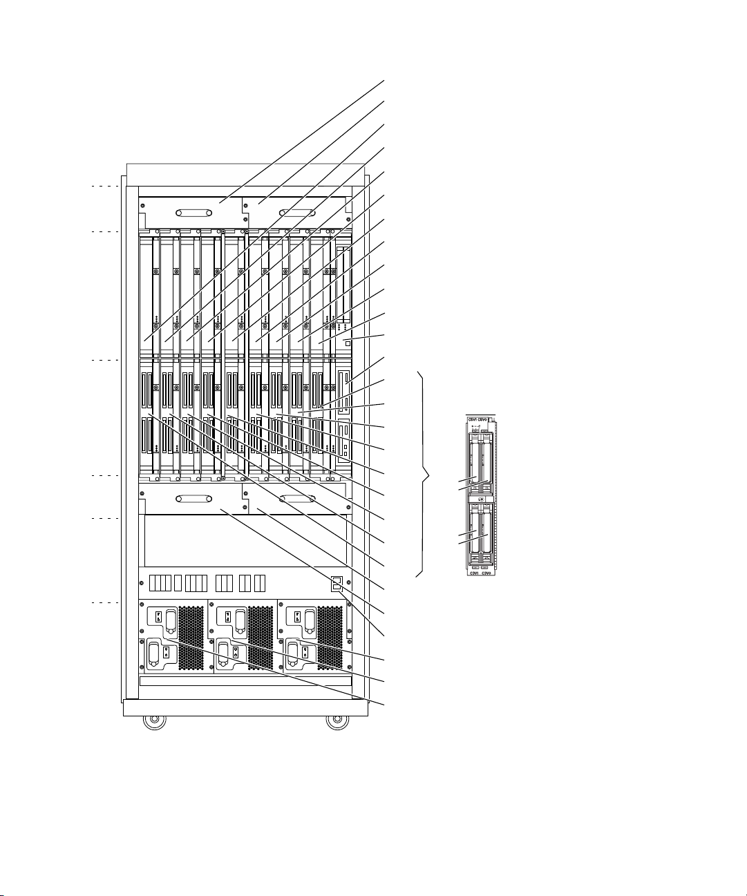
See the front and rear system component numbering (
FIGURE 1-3). See FIGURE 1-4 for cassette component numbering.
Chapter 1 Guidelines, Indicators, and Nomenclature 1-7
FIGURE 1-1, FIGURE 1-2 and

or TopCap
FrameManager
Fan
Tr ay s
Slot 0
Slot 1
Fan
Tr ay s
Air
Vent
Powe r
Supplies
FT1, fan tray
FT0, fan tray
SB8, standard CPU or CPU filler panel
SB7, standard CPU or CPU filler panel
SB6, standard CPU or CPU filler panel
SB5, standard CPU or CPU filler panel
SB4, standard CPU or CPU filler panel
SB3, standard CPU or CPU filler panel
SB2, standard CPU or CPU filler panel
SB1, standard CPU or CPU filler panel
SB0, standard CPU or CPU filler panel
SC0, System Control CPU and spare cPCI port
SCPER0, DVD-ROM, hard drive, tape drive peripherals
IO options: hsPCI+/hsPCI-X, MaxCPU, I/O filler panel
IO0
IO1
IO2
Cassette Numbering
hsPCI
(See additional hsPCI diagrams in
this document for further detail.)
IO3
IO4
IO5
C5V1
C5V0
IO6
C3V1
IO7
C3V0
IO8
FT2, fan trays
FT3, fan trays
LINK (0, 1), remote power to I/O expansion racks
(not used)
PS0 (AC0, AC1), power supplies
PS1 (AC0, AC1), power supplies
PS2 (AC0, AC1), power supplies
FIGURE 1-1 Sun Fire 15K/12K Systems Component Numbering—Front
1-8 Sun Fire 15K/12K Systems Service Manual • May 2006
Fan
Tr ay s
Slot 0
Slot 1
Fan
Tr ay s
Air
Vent
Powe r
Supplies
FT5, fan tray
FT4, fan tray
SB17, standard CPU or CPU filler panel
SB16, standard CPU or CPU filler panel
SB15, standard CPU or CPU filler panel
SB14, standard CPU or CPU filler panel
SB13, standard CPU or CPU filler panel
SB12, standard CPU or CPU filler panel
SB11, standard CPU or CPU filler panel
SB10, standard CPU or CPU filler panel
SB9, standard CPU or CPU filler panel
SC1, System Control CPU and spare cPCI port
SCPER1, DVD-ROM, hard drive, tape drive peripherals
IO9
IO10
IO11
IO options: hsPCI-X/hsPCI+, MaxCPU, I/O filler panel
Cassette Numbering
hsPCI
(See additional hsPCI diagram in
this document for further detail.)
IO12
IO13
IO14
C5V1
C5V0
IO15
C3V1
IO16
C3V0
IO17
FT6, fan trays
C3V1C3V0
FT7, fan trays
LINK (2, 3), remote power to I/O expansion racks
(not used)
PS3 (AC0, AC1), power supplies
PS4 (AC0, AC1), power supplies
PS5 (AC0, AC1), power supplies
FIGURE 1-2 Sun Fire 15K System Component Numbering—Rear
Chapter 1 Guidelines, Indicators, and Nomenclature 1-9

Fan
Tr ay s
Slot 0
Slot 1
Fan
Tr ay s
Air
Vent
Powe r
Supplies
FT5, fan tray
FT4, fan tray
SB17, CPU filler panel
SB16, CPU filler panel
SB15, CPU filler panel
SB14, CPU filler panel
SB13, CPU filler panel
SB12, CPU filler panel
SB11, CPU filler panel
SB10, CPU filler panel
SB9, CPU filler panel
SC1, System Control CPU and spare cPCI port
SCPER1, DVD-ROM, hard drive, tape drive peripherals
IO9
IO10
IO11
IO12
IO13
I/O Filler panels
IO14
IO15
IO16
IO17
FT6, fan trays
FT7, fan trays
LINK (2, 3), remote power to I/O expansion racks
(not used)
PS3 (AC0, AC1), power supplies
PS4 (AC0, AC1), power supplies
PS5 (AC0, AC1), power supplies
FIGURE 1-3 Sun Fire 12K System Component Numbering—Rear
1-10 Sun Fire 15K/12K Systems Service Manual • May 2006

hsPCI+
Cassette interchange diagram
C5V1, hsPCI 33 MHz, yellow
C5V0, hsPCI 33 MHz, blue
C3V1, hsPCI 66 or 33 MHz, yellow
C3V0, hsPCI 66 or 33 MHz, yellow
C3V2, hsPCI-X 90, 66, or 33 MHz, yellow
C5V0, hsPCI-X 33 MHz, blue
Actual I/Os
3.3V and 5.0V
cassettes
3.3V cassettes
3.3V and 5.0V
cassettes
hsPCI-X
C3V1, hsPCI-X 90, 66, or 33 MHz, yellow
C3V0, hsPCI-X 90, 66, or 33 MHz, yellow
3.3V cassettes
FIGURE 1-4 Cassette Component Numbering—Sun Fire 15K Front and Rear, and Sun Fire
12K Front
Note – The 3.3V cassette positions are interchangeable and the 5.0V cassette
positions are interchangeable.
Chapter 1 Guidelines, Indicators, and Nomenclature 1-11

1.8 Safety Precautions
For your protection, observe the following safety precautions when setting up your
equipment:
■ Follow all cautions and instructions marked on the equipment.
■ Never push objects of any kind through openings in the equipment as they might
touch dangerous voltage points or short out components that could result in fire
or electric shock.
■ Refer servicing of equipment to qualified personnel.
To protect both yourself and the equipment, observe the safety precautions outlined
in
TABLE 1-6.
TABLE 1-6 Safety Precautions
Item Problem Precaution
ESD wrist
strap
ESD mat ESD An approved ESD mat provides protection from static
Electro-Static
Discharge
(ESD)
There are four ground points on the system cabinet, two at
the front top left and top right, and two at the rear top left
and top right.
damage when used with a wrist strap. The mat also cushions
and protects parts that are attached to the printed circuit
boards.
1-12 Sun Fire 15K/12K Systems Service Manual • May 2006

1.9 Special Tools and Shipping Kit Items
The following list represents the special tools and items supplied in the shipping kit
box at the time of system delivery:
Special Tools and Shipping Kit Items
Special Tools in Right-Front Door
Two (2) preset 18 in.-lbs (2.2 Nm) torque screwdrivers
Special Tools in Shipping Kit:
Two (2) system control console cables
One (1) 11 in. (27.9 cm) magnetic, replaceable-tip screwdriver
One (1) No. 1 Phillips head bit
One (1) No. 2 Phillips head bit
Other Shipping Kit Items:
I/O cable labels
Power cable labels
Velcro straps for I/O cables
ESD Kit with large mat:
Wrist strap
Static mat, 24 in. (61.0 cm) x 24 in. (61.0 cm)
Envelope, plastic bag
ESD kit instructions
Chapter 1 Guidelines, Indicators, and Nomenclature 1-13

1.10 System Block Diagrams
FIGURE 1-5 defines the Sun Fire 15K/12K systems architecture.
FIGURE 1-6 defines the power control system circuitry from the System Control
boards to the individual power supplies and the fan trays.
FIGURE 1-7 defines the power distribution circuitry. This diagram represents the
48 VDC power distribution from the individual power supplies to the various
boards through the designated circuit breakers.
18 x 18 addresses,
responses, and
data crossbars
on Logic Centerplane
Full-width
board
Half-width
board
Full bandwidth (4.8 Gbps) board type
• 4 CPU / 4 memory banks
FIGURE 1-5 System Architecture Block Diagram
Expander
board
Address
Response
Data
3 half bandwidth (2.4 Gbps) board types
Full-width
Expander
board
• 4 PCI adapters
• 2 CPU / 0 memory banks
• 2 PCI adapters / 3 WCI links
board
Half-width
board
1-14 Sun Fire 15K/12K Systems Service Manual • May 2006

TopCap
FrameManager
12V
12V
12V
RS-232
SC0_I2C (54)
side 0side 1
Present (18)
Interrupt (6)
System Control board
12V
RS-232
2
C (54)
SC1_I
Present (18)
Interrupt (6)
RS-232
RS-232
RS-232
Powe r
Centerplane
To remote frame
(connectors located on
front power module)
To remote frame
(connectors located on
rear power module)
SC0 I2C (8)
SC1 I
Present (4)
SC0 I2C (9)
SC1 I
Present (3)
Interrupt (3)
2
2
C (8)
C (9)
48 Volts
48 Volts
48 Volts
48 Volts
Fan Tray
FT0
Fan Tray
FT1
Fan Tray
FT2
Fan Tray
FT3
Power Supply
PS0
Power Supply
PS1
Power Supply
PS2
Fan Tray
FT4
Fan Tray
FT5
Fan backplaneFan backplane
bottom front top front
top rear
Fan backplaneFan backplane
System Control board
48 Volts
2
C (8)
SC0 I
2
C (8)
SC1 I
Present (4)
2
SC0 I
C (9)
SC1 I2C (9)
Present (3)
Interrupt (3)
FIGURE 1-6 Control Distribution Block Diagram
Chapter 1 Guidelines, Indicators, and Nomenclature 1-15
48 Volts
Fan Tray
FT6
Fan Tray
FT7
Power Supply
PS3
Power Supply
PS4
Power Supply
PS5
bottom rear

Front
Rear
Power Supply
PS0
Power Supply
PS1
Power Supply
PS2
Power Supply
PS3
Power Supply
PS4
Power Supply
PS5
+48 volt
return
+48 volt
return
+48 Volts
+48 Volts
+48 Volts
+48 Volts
+48 Volts
+48 Volts
Fan Bottom Side1
Fan Top Side1
Fan Bottom Side0
Fan Top Side0
System Control Peripheral 0
System Control Board 0
Centerplane Support Board 0
System Expander 0
System Expander 1
System Expander 2
System Expander 3
System Expander 4
System Expander 5
System Expander 6
System Expander 7
System Expander 8
System Expander 8
System Expander 7
System Expander 6
System Expander 5
System Expander 4
System Expander 3
System Expander 2
System Expander 1
System Expander 0
Centerplane Support 0
System Control Board 0
System Control Peripheral 0
Fan Backplane 0.0
Fan Backplane 0.1
Fan Bottom Side 1
Fan Top Side 1
Fan Bottom Side 0
Fan Top Side 0
System Control Peripheral 1
System Control 1
Centerplane Support Board 1
System Expander 9
System Expander 10
System Expander 11
System Expander 12
System Expander 13
System Expander 14
System Expander 15
System Expander 16
System Expander 17
System Expander 17
System Expander 16
System Expander 15
System Expander 14
System Expander 13
System Expander 12
System Expander 11
System Expander 10
System Expander 9
Centerplane Support 1
System Control Board 1
System Control Peripheral 1
Fan Backplane 1.0
Fan Backplane 1.1
BreakersSystem ComponentSystem Component Breakers
FIGURE 1-7 Power Distribution Block Diagram
1-16 Sun Fire 15K/12K Systems Service Manual • May 2006

CHAPTER
2
FrameManager and Extension, and TopCap and Extension Replacement Procedures
The FrameManager assembly and FrameManager extension appear on some of the
Sun Fire 15K/12K systems and the TopCap assembly and TopCap extension appear
on other Sun Fire 15K/12K systems. For those systems, this chapter contains the
replacement procedures for both assemblies and their extensions.
The chapter contains the following sections:
■ Section 2.1, “FrameManager Replacement” on page 2-2
■ Section 2.1.1, “Removing the FrameManager” on page 2-2
■ Section 2.1.2, “Installing the FrameManager” on page 2-2
■ Section 2.2, “FrameManager Extension Replacement” on page 2-2
■ Section 2.2.1, “Removing the FrameManager Extension” on page 2-2
■ Section 2.2.2, “Installing the FrameManager Extension” on page 2-3
■ Section 2.3, “TopCap Replacement” on page 2-3
■ Section 2.3.1, “Removing the TopCap” on page 2-3
■ Section 2.3.2, “Installing the TopCap” on page 2-3
■ Section 2.4, “TopCap Extension Replacement” on page 2-4
■ Section 2.4.1, “Removing the TopCap Extension” on page 2-4
■ Section 2.4.2, “Installing the TopCap Extension” on page 2-4
For your protection, also observe the following safety precautions when setting up
your equipment:
■ Follow all cautions and instructions marked on the equipment.
■ Always use proper ESD equipment and procedures when handling boards and
components.
■ Never push objects of any kind through openings in the equipment as they might
touch dangerous voltage points or short out components that can result in fire or
electric shock.
■ Refer servicing of equipment to qualified personnel.
2-1

2.1 FrameManager Replacement
2.1.1 Removing the FrameManager
Caution – Be sure you are properly grounded before you begin the hardware
removal and installation. There are four ground points on the system cabinet, two at
the front top left and top right, and two at the rear top left and top right.
1. Remove the four (4) M4x12 panhead screws attaching the FrameManager assembly
to the chassis.
2. Disconnect the four (4) cable connectors from the rear of the FrameManager
assembly.
3. Remove the FrameManager assembly.
2.1.2 Installing the FrameManager
1. Install a new FrameManager assembly.
2. Connect the four (4) cable connectors to the rear of the FrameManager assembly.
3. Secure the FrameManager assembly with four (4) M4x12 panhead screws.
2.2 FrameManager Extension Replacement
2.2.1 Removing the FrameManager Extension
1. Remove the two (2) M4x12 panhead screws attaching the FrameManager extension
to the chassis.
2. Remove the FrameManager extension.
2-2 Sun Fire 15K/12K Systems Service Manual • May 2006

2.2.2 Installing the FrameManager Extension
1. Install a new FrameManager extension.
2. Secure the FrameManager extension with two (2) M4x12 panhead screws.
2.3 TopCap Replacement
2.3.1 Removing the TopCap
Caution – Be sure you are properly grounded before you begin the hardware
removal and installation. There are four ground points on the system cabinet, two at
the front top left and top right, and two at the rear top left and top right.
1. Remove the four (4) M4x12 panhead screws attaching the TopCap assembly to the
chassis.
2. Disconnect the 12V cable connector from the rear of the TopCap assembly.
3. Remove the TopCap assembly.
2.3.2 Installing the TopCap
If you are removing a FrameManager assembly prior to installing a replacement
TopCap assembly, see Section 2.1.1, “Removing the FrameManager” on page 2-2.
Note – If you are replacing a FrameManager assembly with a TopCap, follow the
procedure outlined in the documentation that accompanies the TopCap FRU
package.
1. Install a new TopCap assembly.
2. Connect the 12V cable connector to the rear of the TopCap assembly.
3. Secure the TopCap assembly with four (4) M4x12 panhead screws.
Chapter 2 FrameManager and Extension, and TopCap and Extension Replacement Procedures 2-3

2.4 TopCap Extension Replacement
2.4.1 Removing the TopCap Extension
1. Remove the two (2) M4x12 panhead screws attaching the TopCap extension to the
chassis.
2. Remove the TopCap extension.
2.4.2 Installing the TopCap Extension
1. Install the new TopCap extension.
2. Secure the TopCap extension with two (2) M4x12 panhead screws.
2-4 Sun Fire 15K/12K Systems Service Manual • May 2006

CHAPTER
3
System Power
The Sun Fire 15K/12K systems have two power modules, each holding three hotswappable power supplies. One module is on the front of the system and the other
module is on the rear of the system. This chapter contains the replacement
procedures for the power modules and the 4 kW dual AC–DC power supplies.
This chapter contains the following sections:
■ Section 3.1, “Power Module Replacement Procedures” on page 3-2
■ Section 3.1.1, “Power Module Replacement” on page 3-2
■ Section 3.1.2, “Powering Off for Power Module Removal” on page 3-2
■ Section 3.1.3, “Removing a Power Module” on page 3-4
■ Section 3.1.4, “Installing a Power Module” on page 3-6
■ Section 3.1.5, “Powering On After Power Module Installation” on page 3-7
■ Section 3.2, “4 kW Dual AC–DC Power Supply Replacement Procedures” on
page 3-8
■ Section 3.2.1, “4 kW Dual AC–DC Power Supply LEDs” on page 3-9
■ Section 3.2.2, “4 kW Dual AC–DC Power Supply Replacement” on page 3-10
For your protection, also observe the following safety precautions when setting up
your equipment:
■ Follow all cautions and instructions marked on the equipment.
■ Always use proper ESD equipment and procedures when handling boards and
components.
■ Never push objects of any kind through openings in the equipment as they might
touch dangerous voltage points or short out components that can result in fire or
electric shock.
■ Refer servicing of equipment to qualified personnel.
3-1

3.1 Power Module Replacement Procedures
3.1.1 Power Module Replacement
The Sun Fire 15K/12K systems have two power modules, each holding three power
supplies. One module is on the front of the system and the other module is on the
rear of the system. See
3.1.2 Powering Off for Power Module Removal
Caution – The power module is NOT a hot-swappable component. This procedure
requires a complete shutdown of the domains and SCs, and disconnection of all AC
power to the system.
There are four ground points on the system cabinet, two at the front top left and top
right, and two at the rear top left and top right.
Caution – The seven (7) power cables and the three (3) control cables MUST BE
REMOVED from the side of the system where the power module is being removed.
FIGURE 3-2.
1. As a superuser on the domains, systematically shut down all running domains
by typing:
domain_name# shutdown -y -g seconds -i 0
where seconds = amount of time before shutdown.
2. On the main SC, power off the domain hardware by typing:
sc% poweroff
This command powers off the entire system with the exception of the power
supplies, fans, and the SCs. Refer to poweroff(1M) for more information.
3-2 Sun Fire 15K/12K Systems Service Manual • May 2006

3. Shut down the System Control boards by doing the following:
■ As a superuser on the spare SC, shut down the spare SC by typing:
sc_spare# shutdown -y -g seconds -i 0
where seconds = amount of time before shutdown.
■ On the main SC, power off the spare SC by typing:
sc% poweroff SCx
where x = 0-1, dependent upon which SC is the spare.
■ As a superuser on the main SC, shutdown the main SC by typing:
sc# shutdown -y -g seconds -i 0
where seconds = amount of time before shutdown.
4. Open the Sun Fire 15K/12K system cabinet access doors.
Note – All DC circuit breakers are to remain in the on position at all times.
5. Power off the AC0 and AC1 circuit breakers for all power supplies in the system.
Note – Observe the following warning message displayed at the right side of the
circuit breakers on the circuit breaker panel above the AC power supplies:
WARNING
FAN TRAYS HAVE REDUNDANT DC POWER SOURCES.
CIRCUIT BREAKERS ON BOTH SIDES, FRONT AND REAR,
MUST BE OPERATED TO TURN OFF FAN TRAYS.
POWER SUPPLIES HAVE DUAL AC INPUTS.
BOTH CIRCUIT BREAKERS, AC0 AND AC1 MUST BE
OPERATED TO TURN OFF A POWER SUPPLY.
Chapter 3 System Power 3-3

3.1.3 Removing a Power Module
Caution – Be sure you are properly grounded before you begin the hardware
removal and installation of the board.
There are four ground points on the system cabinet, two at the front top left and top
right, and two at the rear top left and top right.
1. Label and disconnect the twelve (12, six per side) AC power cords with the labels
provided in the shipping kit.
2. Remove the power supplies from the power module.
See Section 3.2.2.3, “Removing a 4 kW Dual AC–DC Power Supply” on page 3-11.
3. Remove the air-plenum cover by removing the eighteen (18) M4x35 panhead
screws from the top, sides, and bottom of the air-inlet screen (
4. Remove the four (4) M4x8 panhead screws from the side and bottom of the air
plenum panel, at the circuit breaker level.
FIGURE 3-1).
Air plenum cover
M4x35 panhead
screws (18)
M4x8 panhead
screws (4)
Cover cutout for system
circuit breakers
Air-inlet screen
FIGURE 3-1 Air-Plenum Cover
Caution – Handle the EMI honeycomb panel carefully to prevent damage to the
screen.
3-4 Sun Fire 15K/12K Systems Service Manual • May 2006
Air plenum
filter (back
of cover)

5. Remove the air plenum cover and its air-inlet EMI honeycomb panel and air filter.
Place on a flat sturdy surface.
Caution – The seven (7) power cables and the three (3) control cables MUST BE
REMOVED from the system chassis on both the front and rear sides of the system
prior to removing the power module.
6. With a flat-blade screwdriver (if needed), loosen the jackscrews on the seven (7)
8W8 Combo-D 8-pin DC power connectors (on the left side) and the three (3)
DB-25 control connectors (on the right side).
7. Disconnect the cables from the mounting bulkhead of the system chassis.
8. Remove the four (4) M4x10 panhead screws attaching the power module front
flanges to the system chassis, as shown in
FIGURE 3-2.
Caution – The power module weighs 48 lb (21.82 kg). Although the unit can be
lifted by one person, it is suggested that two people, one on each side, maneuver the
power module into position. Use proper heavy-lifting procedures when removing
this unit.
9. With one person on each side of the power module, grasp the front (at the power
supply opening) and the bottom and slide the power module outward from the
cabinet.
10. Place the power module on a flat sturdy surface.
11. From the top rear of the power module, loosen the seven (7) 8W8 Combo-D 8-pin
DC power connectors (on the left side) and the three (3) DB-25 control connectors
(on the right side).
12. Disconnect the cables, and set aside.
Chapter 3 System Power 3-5

DB-9 control connector
to side wall for the
FrameManager
P13 to J13 cable (front)
P12 to J12 cable (rear)
Power module
DC circuit breakers (16)
AC circuit breakers
(2 per power supply)
8W8 Combo-D 8-pin
power connectors (7)
to connector bulkhead
DB-25 control
connectors (2)
to connector bulkhead
DB-25 control connector
to side wall for the
FrameManager
and TopCap
P10 to J10 cable (front)
P11 to J11 cable (rear)
M4x8 panhead screws (4)
Power supplies
(removed prior to power module replacement)
FIGURE 3-2 Power Module
3.1.4 Installing a Power Module
1. At the top rear of the power module, connect and hand tighten the jackscrews of
the seven (7) 8W8 Combo-D 8-pin DC power connectors on the left side and the
three (3) DB-25 control connectors on the right side.
Note – The power module weighs 48 lb (21.82 kg). Although the unit can be lifted
by one person, it is suggested that two people, on each side, maneuver the power
module into position. Use proper heavy-lifting procedures when installing this unit.
2. With one person on each side of the power module, grasp the front (at the power
supply opening) and the bottom and slide the power module into the system
chassis.
3. Secure the power module to the system chassis with the four (4) M4x10 panhead
module-to-system mounting screws, as shown in
M4x10 panhead module-to-system
mounting screws (4)
FIGURE 3-2.
3-6 Sun Fire 15K/12K Systems Service Manual • May 2006

4. Connect the seven (7) 8W8 Combo-D 8-pin DC power connectors (on the left side)
and the three (3) DB-25 control connectors (on the right side) to the mounting
bulkhead of the system chassis, as shown in
jackscrews.
FIGURE 3-2, and hand tighten the
Caution – Handle the EMI honeycomb panel carefully to prevent damage to the
screen.
5. Install the air-plenum cover and its air-inlet EMI honeycomb panel and air filter.
6. Secure with the eighteen (18) M4x35 panhead screws at the top, sides, and bottom
around the air-inlet screen, and the four (4) M4x8 panhead screws at the side and
bottom of the air plenum panel, at the circuit breaker level.
Note – All power supply units are fully interchangeable.
7. Install the 4 kW dual AC input power supplies.
See Section 3.2.2.4, “Installing a 4 kW Dual AC–DC Power Supply” on page 3-12.
8. Ensure that all DC circuit breakers are in the on position.
9. Ensure that all AC circuit breakers are in the off position.
3.1.5 Powering On After Power Module Installation
1. Connect the AC power cords to the 4 kW dual AC–DC power supplies.
2. Power on the AC0 and AC1 circuit breakers for all power supplies in the system.
3. Close the Sun Fire 15K/12K system cabinet access doors.
4. Once the main SC is booted, start the domain(s) by typing:
sc% setkeyswitch -d domain_id on
where domain_id is the domain letter A-R. Execute one setkeyswitch command
for each domain to be started.
Chapter 3 System Power 3-7

3.2 4 kW Dual AC–DC Power Supply
Replacement Procedures
The Sun Fire 15K/12K systems have three 4 kW dual AC–DC hot-swappable power
supplies at the front of the system and three at the rear of the system. See
Top view
Activation indicator (green)
Service indicator (amber)
Removal indicator (amber)
AC0
200-240 VAC
47-63 Hz, 24A
FIGURE 3-3.
AC1
200-240 VAC
47-63 Hz, 24A
FIGURE 3-3 Sun Fire 15K/12K Systems Power Supply
3-8 Sun Fire 15K/12K Systems Service Manual • May 2006
Right-side viewFront view Rear view

3.2.1 4 kW Dual AC–DC Power Supply LEDs
4 kW Dual AC–DC power supply components and LEDs are listed in TABLE 3-1 and
TABLE 3-2.
TABLE 3-1 4 kW Dual AC–DC Power Supply Components
Total Number of Power Supplies
Per System
Total Number of LEDs Per
Power Supply
63
TABLE 3-2 4 kW Dual AC–DC Power Supply Valid LED Status
LEDs after Insertion
or Initial System Power On
Active Service Remove Active Service Remove Active Service Remove Active Service Remove
LEDs After PRESENCE
is Detected Component Powered On
*
Component Powered Off
on off off off off on on off off off off on
* ON = AC0_FAIL_L = H or AC1_FAIL_L = H
\ OFF = AC0_FAIL_L = L and AC1_FAIL_L = L
Failure of the active LED to transition from ON to OFF within 60 seconds after
insertion indicates a power-status control fault.
FIGURE 3-4 illustrates the power supply and the LED locations.
\
Chapter 3 System Power 3-9

AC0
Activation indicator (green)
Service indicator (amber)
Removal indicator (amber)
AC1
FIGURE 3-4 4 kW Dual AC–DC Power Supply LEDs
3.2.2 4 kW Dual AC–DC Power Supply Replacement
3.2.2.1 Isolating a Failed Power Supply
1. Check that the power supply fans are on.
2. Verify the status of the LEDs.
3. Confirm that the power supply is properly seated.
4. Check the power status by using the Sun Management Center or by typing the
following SMS command:
sc% showenvironment -p powers
5. On the SC, check for error messages in
/var/opt/SUNWSMS/adm/platform/messages.
3-10 Sun Fire 15K/12K Systems Service Manual • May 2006

3.2.2.2 Powering Off a 4 kW Dual AC–DC Power Supply
● Power off the AC–DC power supply by using the Sun Management Center or by
typing the following SMS command:
sc% poweroff psx
where x is the power supply 0-5. Refer to poweroff(1M) for more information.
This should cause the AC0 and AC1 circuit breakers to go into the off position.
3.2.2.3 Removing a 4 kW Dual AC–DC Power Supply
Caution – Be sure you are properly grounded before you begin the hardware
removal and installation. There are four ground points on the system cabinet, two at
the front top left and top right, and two at the rear top left and top right.
1. Open the Sun Fire 15K/12K system cabinet access doors.
Caution – Before removing the power supply from the system, the green activation
LED must be off and the amber removal OK LED must be on. See Section 3.2.2.2,
“Powering Off a 4 kW Dual AC–DC Power Supply” on page 3-11.
Note – Observe the following warning message displayed at the right of the circuit
breakers on the circuit breaker panel above the AC power supplies.
WARNING
FAN TRAYS HAVE REDUNDANT DC POWER SOURCES.
CIRCUIT BREAKERS ON BOTH SIDES, FRONT AND REAR,
MUST BE OPERATED TO TURN OFF FAN TRAYS.
POWER SUPPLIES HAVE DUAL AC INPUTS.
BOTH CIRCUIT BREAKERS, AC0 AND AC1 MUST BE
OPERATED TO TURN OFF A POWER SUPPLY.
2. Ensure power is off at the circuit breakers, AC0 (top breaker) and AC1 (bottom
breaker), on the front panel of the power supply.
Note – Ensure all AC power cords are labeled before removing.
Chapter 3 System Power 3-11
3. Label and remove both AC power cords from the front panel of the power supply.
Caution – The power supply unit weighs 43.0 lb (19.5 kg). Use proper heavy-lifting
procedures when removing this unit.
4. Use a Phillips No. 2 screwdriver to release the four (4) front panel captive
fasteners.
5. To pull out the 4 kW dual AC–DC power supply, use the power connector insertejector bracket as a handle and slide the power supply forward until the handle
on the top of the power supply is exposed.
6. Use one hand to hold the power supply by the handle as you pull it the rest of the
way out of the power module.
7. Place the power supply on a flat, sturdy, ESD-protected surface.
3.2.2.4 Installing a 4 kW Dual AC–DC Power Supply
Caution – The power supply unit weighs 43.0 lb (19.5 kg). Use proper heavy-lifting
procedures when removing this unit.
1. Insert the 4 kW dual
AC–DC power supply into its appropriate location in the
power module.
2. Slide the power supply smoothly inward to a point where contact is made with
the power module connector.
3. Secure the power supply with the four (4) front panel captive fasteners.
Note – Failure of the active LED to transition from on to off within 60 seconds after
insertion indicates a power-status control fault.
4. Verify the LED status per
TABLE 3-2.
5. Connect the AC power cords into their appropriate AC connectors on the front
panel of the power supply.
See
FIGURE 3-5 to determine the proper part number and orientation for connection.
■ The strain relief for the AC0 power cable housing is positioned downward when
connected.
■ The strain relief for the AC1 power cable housings is positioned upward when
connected.
3-12 Sun Fire 15K/12K Systems Service Manual • May 2006

■ Power source A cord will normally connect into AC0.
■ Power source B cord will normally connect into AC1.
PS0 (PS3 rear)
PS1 (PS4 rear)
PS2 (PS5 rear)
AC0
Power cable
strain relief
PS and AC
power cable
label
Front view shown
FIGURE 3-5 AC Power Cord Installation
AC1
6. Affix the appropriate power supply component label to the back of the power
cable connector housing.
3.2.2.5 Powering On a 4 kW Dual AC–DC Power Supply
1. Power on the circuit breakers, AC0 (top breaker) and AC1 (bottom breaker), on the
front panel of the power supply.
2. Close the Sun Fire 15K/12K system cabinet access doors.
3.2.2.6 Verifying a 4 kW Dual AC–DC Power Supply
1. On the SC, check for error messages in
/var/opt/SUNWSMS/adm/platform/messages.
2. Check the power supply status by using the Sun Management Center or by typing
the following SMS command:
sc% showenvironment -p powers
POWER UNIT AC0 AC1 DC0 DC1 FAN0 FAN1
------ ------ ---- ---- ---- ---- ---- ---PS0 OK OK OK ON ON OK OK
...
Chapter 3 System Power 3-13

3-14 Sun Fire 15K/12K Systems Service Manual • May 2006

CHAPTER
4
Fan Trays
The Sun Fire 15K/12K systems have eight hot-swappable fan trays. Each fan tray
has two layers of six fans for a total of twelve fans per tray. There are two fan trays
at the top and two fan trays at the bottom on both the front and rear of the system.
See
FIGURE 4-1. This chapter contains the replacement procedures for the fan trays.
Guide pin
(left side only)
FIGURE 4-1 Fan Tray
All fan trays are interchangeable.
This chapter contains the following sections:
■ Section 4.1, “Fan Tray LEDs” on page 4-2
■ Section 4.2, “Fan Tray Replacement Procedures” on page 4-3
■ Section 4.2.1, “Isolating a Failed Fan Tray” on page 4-3
■ Section 4.2.2, “Powering Off a Fan Tray” on page 4-4
■ Section 4.2.3, “Removing a Fan Tray” on page 4-4
■ Section 4.2.4, “Installing a Fan Tray” on page 4-5
■ Section 4.2.5, “Verifying a Fan Tray” on page 4-6
4-1

For your protection, also observe the following safety precautions when setting up
your equipment:
■ Follow all cautions and instructions marked on the equipment.
■ Always use proper ESD equipment and procedures when handling boards and
components.
■ Never push objects of any kind through openings in the equipment as they might
touch dangerous voltage points or short out components that can result in fire or
electric shock.
■ Refer servicing of equipment to qualified personnel.
4.1 Fan Tray LEDs
Fan tray components and LEDs are listed in TABLE 4-1 and TABLE 4-2.
TABLE 4-1 Fan Tray Components
Total Number of Fan Trays
Per System Per Side
Total Number of Fan Trays
Per Fan Shelf Per Side
Number of LEDs Per
Fan Tray
Number of Fans Per
Fan Tray
42312
TABLE 4-2 Fan Tray Valid LED Status
LEDs after Insertion
or Initial System Power On
Active Service Remove Active Service Remove Active Service Remove Active Service Remove
LEDs After PRESENCE
is Detected Component Powered On Component Powered Off
on off off on off off on off off off off on
FIGURE 4-2 illustrates the fan tray and the LED locations.
4-2 Sun Fire 15K/12K Systems Service Manual • May 2006

This system contains
four fan trays per side and
twelve fans per tray.
FIGURE 4-2 Fan Tray LEDs
Activation indicator (green)
Service indicator (amber)
Removal indicator (amber)
4.2 Fan Tray Replacement Procedures
4.2.1 Isolating a Failed Fan Tray
1. Check that the fans are on.
2. Verify the status of the LEDs.
3. Check the fan status by using the Sun Management Center or by typing the
following SMS command:
sc% showenvironment -p fans
4. Check the /var/opt/SUNWSMS/adm/platform/messages file for fan error
messages.
Chapter 4 Fan Trays 4-3

4.2.2 Powering Off a Fan Tray
● Power off a fan tray by using the Sun Management Center or by typing the
following SMS command:
sc% poweroff ftx
where x is the Fan Tray 0-7. Refer to poweroff(1M) for more information.
Caution – To maintain adequate system cooling during fan tray replacement, limit
the amount of time a fan is off. DO NOT remove a failed fan tray from the system
until the replacement tray is ready for installation.
4.2.3 Removing a Fan Tray
Caution – Be sure you are properly grounded before you begin the hardware
removal and installation. There are four ground points on the system cabinet, two at
the front top left and top right, and two at the rear top left and top right.
Note – When removing the upper fan trays, remember the bottom system kick plate
is NOT A STEP. DO NOT use the kick plate to gain access to the top fan trays.
Obtain a proper stool if required. Excessive weight on the kick plate will bend the
door support brackets.
1. Open the Sun Fire 15K/12K system cabinet access doors.
Caution – Before removing the fan tray from the system, the green activation LED
must be off and the amber removal OK LED must be on. See Section 4.2.2,
“Powering Off a Fan Tray” on page 4-4.
2. Release the two (2) fan tray front panel No. 2 Phillips captive screw fasteners.
Caution – The fan tray weighs 24.0 lb (11.0 kg). Use proper heavy-lifting procedures
when removing this unit.
4-4 Sun Fire 15K/12K Systems Service Manual • May 2006

3. Grasp the handle and pull the fan tray outward.
As the tray slides forward, the guide pin on the left side of the tray comes up to a
45-degree upward angle on the bi-level groove approximately 3/4ths of the way out.
This is a safety feature alerting you to stop pulling and to place the other hand under
the fan tray.
4. Continue lifting up and pulling outward on the guide rail pulling the fan tray out
with both hands away from the system chassis.
5. Place the fan tray on a flat sturdy surface.
4.2.4 Installing a Fan Tray
Caution – The fan tray weighs 24.0 lb (11.0 kg). Use proper heavy-lifting procedures
when removing this unit.
1. Grasp the fan tray by the handle with one hand and support the bottom of the fan
tray with the other hand.
2. Insert the fan tray into the system chassis aligning the guide pin on the left side
of the tray with the left guide rail of the angled guide ramp and slide the fan tray
into the chassis.
It will go in approximately one fourth of the way and drop down about
0.2 in. (.5 cm).
3. Slide the fan tray inward until it connects with the connector of the fan
backplane.
4. Using firm, steady pressure, fully insert the fan tray until it is fully seated with
the fan backplane connector.
5. Secure the two (2) front panel captive screw fasteners.
Note – Failure of the service LED to transition from on to off within 60 seconds after
insertion indicates a power-status control fault.
6. Verify the LED status per
7. Close the Sun Fire 15K/12K system cabinet access doors.
TABLE 4-2.
Chapter 4 Fan Trays 4-5

4.2.5 Verifying a Fan Tray
1. On the SC, check for error messages in
/var/opt/SUNWSMS/adm/platform/messages.
2. Check the fan tray status by using the Sun Management Center or by typing the
following SMS command:
sc% showenvironment -p fans
FANTRAY POWER SPEED FAN0 FAN1 FAN2 FAN3 FAN4 FAN5 FAN6
------ ------ ----- ---- ---- ---- ---- ---- ---- ---FT0 ON HIGH OK OK OK OK OK OK OK
...
4-6 Sun Fire 15K/12K Systems Service Manual • May 2006

CHAPTER
5
System Control (SC) CPU Board and cPCI Memory Board
The System Control (SC) board (slot 0) for the Sun Fire 15K/12K systems support
the SC CPU board and its cPCI memory board. This chapter contains the
replacement procedures for the SC CPU board and the installation procedures for
the cPCI memory board onto the SC CPU.
This chapter contains the following sections:
■ Section 5.1, “System Control (SC) CPU Board Replacement Procedures” on
page 5-2
■ Section 5.1.1, “Powering Off the SC Board” on page 5-2
■ Section 5.1.2, “Removing the SC Board” on page 5-2
■ Section 5.1.3, “Removing the System Control (SC) CPU Board” on page 5-2
■ Section 5.2, “System Control (SC) Board cPCI Memory Board Installation
Procedures” on page 5-3
■ Section 5.2.1, “Installing cPCI Memory Boards on the SC CPU” on page 5-3
■ Section 5.2.2, “Installing the System Control (SC) CPU Board” on page 5-5
■ Section 5.2.3, “Installing the System Control (SC) Board” on page 5-5
■ Section 5.2.4, “Verifying the cPCI Memory Boards on the SC CPU” on page 5-6
For your protection, also observe the following safety precautions when setting up
your equipment:
■ Follow all cautions and instructions marked on the equipment.
■ Always use proper ESD equipment and procedures when handling boards and
components.
■ Never push objects of any kind through openings in the equipment as they might
touch dangerous voltage points or short out components that can result in fire or
electric shock.
■ Refer servicing of equipment to qualified personnel.
5-1

5.1 System Control (SC) CPU Board Replacement Procedures
Caution – Be sure you are properly grounded before you begin the hardware
removal and installation. There are four ground points on the system cabinet, two at
the front top left and top right, and two at the rear top left and top right.
The SC CPU is not a hot swappable component. Damage can occur to the board if all
power down procedures are not followed as detailed in this manual.
Caution – Before removing a board from the system, the green activation LED must
be off and the amber removal OK LED must be on. See Section 6.1.2.2, “Powering
Off a System Control (SC) Board” on page 6-4.
5.1.1 Powering Off the SC Board
● Powering off the SC Board.
See Section 6.1.2.2, “Powering Off a System Control (SC) Board” on page 6-4.
5.1.2 Removing the SC Board
● Removing the SC Board.
See Section 6.1.2.3, “Removing a System Control (SC) Board” on page 6-7.
5.1.3 Removing the System Control (SC) CPU Board
1. Release the two (2) captive screws holding the SC CPU to the SC board.
2. Remove the SC CPU board by using the insert-eject levers on the board.
5-2 Sun Fire 15K/12K Systems Service Manual • May 2006

5.2 System Control (SC) Board cPCI Memory Board Installation Procedures
Inspect the new board before inserting it into the Sun Fire 15K/12K systems.
1. Remove the connector protective cover from the board being installed and inspect
the connector for any damaged or gaps between the pins.
2. Ensure any board alignment tabs are not bent.
3. Inspect the mating connector before inserting the new board.
Caution – Do not force any board into a slot; it can cause damage to the board and
the system. The board should insert and seat smoothly. If it binds, remove the board
and inspect the card cage slot for any obvious obstructions.
5.2.1 Installing cPCI Memory Boards on the SC CPU
Caution – Be sure you are properly grounded before you begin the hardware
removal and installation. There are four ground points on the system cabinet, two at
the front top left and top right, and two at the rear top left and top right.
The SC CPU board can support up to two memory boards and two possible
configurations. One installation configuration consists of two 128-Mbyte modules.
The first memory board (memory board A) is installed directly onto the SC CPU
board. The second memory board (memory board B) is installed directly on top of
memory board A (
module (memory board A).
1. Determine if one or two memory boards are being installed for this installation
and locate the 2-56 x 3/8 in. or 2-56 x 3/16 in. screws, the M2 flat washers, the M2
split-lock washers, and the 2-56 x 3/16 in. spacers, as required.
Note – If you are installing only one memory board, do not use the plastic spacers
and the 2-56 x 3/8 in. screws. Install the board using the washers and 2-56 x 3/16 in.
screws directly into the metal mounting posts.
■ If you are installing the single memory board configuration, follow Step 2 through
Step 4.
FIGURE 5-1). The second configuration is a single 256-Mbyte
Chapter 5 System Control (SC) CPU Board and cPCI Memory Board 5-3

Phillips panhead screw
2-56 x 3/8 in. (4)
M2 split-lock washer (4)
M2 flat washer (4)
Nylon spacer
2-56 x 3/16 in. (4)
Memory board
connectors
Memory board
part number
Memory board B
Memory board A
Metal mounting post (4)
FIGURE 5-1 System Control (SC) CPU cPCI Memory Board Installation
■ If you are installing the double memory board configuration, follow Step 2, and
SC CPU board
Step 4 through Step 8.
2. Align the three memory board A connectors above the memory board connector
sockets on the SC CPU board and press down firmly, ensuring the three
connectors are properly seated.
3. Align the flat washers and the split-lock washers on top of memory board A, and
secure into the metal mounting posts with the 2-56 x 3/16 in. Phillips panhead
screws.
Note – To avoid micro-fracture damage to the SC CPU board, do not apply
excessive pressure on any of the connectors.
4. Press on the third, or middle, connector to ensure it is properly seated.
5-4 Sun Fire 15K/12K Systems Service Manual • May 2006

Note – The remaining steps are for the two memory-board installation.
5. Place the round nylon spacers on top of the mounting holes on memory board A.
6. Align the three memory board B connectors on top of the memory board A
connector sockets and press down firmly ensuring the three connectors are
properly seated in memory board B.
7. Align the flat washers and the split-lock washers on top of memory board B,
secure with the 2-56 x 3/8 in. Phillips panhead screws, ensuring the spacers are
secure between memory board A and memory board B.
8. Press on the third, or middle connector on memory board B to ensure it is
properly seated.
5.2.2 Installing the System Control (SC) CPU Board
1. Install the correctly configured SC CPU board and lock the insert-eject levers into
position.
2. Secure the SC CPU to the SC board with the two (2) captive screws.
3. Connect all I/O cables.
4. Power on the SC by using the Sun Management Center or from the main SC by
typing the following SMS command:
sc% resetsc
About to reset other SC. Are you sure you
want to continue? (yes/no)? yes
5. Verify the SC board.
See Section 6.1.2.5, “Verifying a System Control (SC) Board” on page 6-10.
5.2.3 Installing the System Control (SC) Board
● Installing the SC board.
See Section 6.1.2.4, “Installing a System Control (SC) Board” on page 6-8.
Chapter 5 System Control (SC) CPU Board and cPCI Memory Board 5-5

5.2.4 Verifying the cPCI Memory Boards on the SC CPU
1. Verifying the SC board.
See Section 6.1.2.5, “Verifying a System Control (SC) Board” on page 6-10.
Note – Memory failure might occur due to the installation of an incorrect memory
board, memory board failure, or improper installation.
2. After the installation of the SC board, the system goes through SCPOST and
OpenBoot PROM (OBP). Review the messages on the console.
If a problem is found with the memory, an error message is displayed. The memory
configuration is recognized in groups indicated as Group 0, Group 1, Group 2, and
Group 3. For two memory boards, 128 Mbytes double-sided, single stuffed, the OBP
displays the following configuration information:
Memory Group #0, 64 + 64 : 128 Megabytes
Memory Group #1, 0 + 0 : 0 Megabytes
Memory Group #2, 64 + 64 : 128 Megabytes
Memory Group #3, 0 + 0 : 0 Megabytes
3. If an error is found, check the following for a solution:
■ Ensure the right memory board is installed in the proper slot and properly seated.
■ If two memory boards are installed, ensure each board is installed in the proper
position.
■ Ensure the total memory on the memory board(s) does not exceed the total
memory limit for the processor board.
5-6 Sun Fire 15K/12K Systems Service Manual • May 2006

CHAPTER
6
System Control (SC) Board
The System Control (SC) board for the Sun Fire 15K/12K systems is a hot-swappable
board at SC0 (front) and SC1 (rear). This chapter contains the replacement
procedures for the SC board.
This chapter contains the following sections:
■ Section 6.1, “System Control (SC) Board Replacement” on page 6-2
■ Section 6.1.1, “System Control Board LEDs” on page 6-2
■ Section 6.1.2, “System Control Board (SC) Replacement Procedures” on
page 6-4
For your protection, also observe the following safety precautions when setting up
your equipment:
■ Follow all cautions and instructions marked on the equipment.
■ Always use proper ESD equipment and procedures when handling boards and
components.
■ Never push objects of any kind through openings in the equipment as they might
touch dangerous voltage points or short out components that can result in fire or
electric shock.
■ Refer servicing of equipment to qualified personnel.
6-1

6.1 System Control (SC) Board Replacement
6.1.1 System Control Board LEDs
System Control (SC) board components and LEDs are listed in TABLE 6-1 and
TABLE 6-2.
TABLE 6-1 System Control Board Components
Total Number of System Control
Boards Per System
Total Number of System Control
Boards Per side
Number of LEDs Per System
Control Board
219
TABLE 6-2 System Control Board Valid LED Status
LEDs after Insertion
or Initial System Power On
Active Service Remove Active Service Remove Active Service Remove Active Service Remove
LEDs After PRESENCE
is Detected Component Powered On Component Powered Off
on on off on off off on off off off off on
The SC CPU slot and SC 6U/3U spare slot on the SC board do not have unique bits,
referred to as presence bits. Failure of the service LED to transition from ON to OFF
within 60 seconds after insertion indicates a power-status control fault.
TABLE 6-3 describes the SC CPU board indicator functions.
TABLE 6-3 System Control CPU Board Indicator Function Descriptions
Indicator Functions Description
Alarm Not used
Ready Component ON and board is READY
Reset button Global reset to the SC CPU and PCI reset to the SC
Abort button Resets the CPU
FIGURE 6-1 illustrates the System Control board and the LED locations.
6-2 Sun Fire 15K/12K Systems Service Manual • May 2006

SC CPU board
Alarm indicator (green)
Ready indicator (green)
Reset button
Abort button
Main SC board
Activation indicator (green)
Service indicator (amber)
Removal indicator (amber)
Spare 6U/3U slot*
Activation indicator (green)
Service indicator (amber)
Removal indicator (amber)
SC CPU board
Activation indicator (green)
Service indicator (amber)
Removal indicator (amber)
FIGURE 6-1 System Control Board LEDs (3U to 6U Conversion Board Option)
* The SC 6U/3U spare slot is
not supported at this time.
Caution – Using the SC CPU reset and SC CPU abort hardware buttons might
corrupt the operating system disk if the operating system has not been properly shut
down.
■ SC CPU Reset Button
When the RESET button on the front panel of the SC CPU (CP1500) board is
pressed, a Power-on-reset (POR) is generated to the SC CPU board and a
peripheral component interconnect (PCI) reset is generated to the PCI devices on
the SC main board. This results in a general clearing of the SC CPU board to a
power on state, and a reset of the PCI bus on the SC main board.
Using the RESET button will reboot the operating system on the SC if the
appropriate OpenBoot PROM (OBP) environment variables have been set.
Chapter 6 System Control (SC) Board 6-3

■ SC CPU Abort Button
When the ABORT button on the front panel of the SC CPU (CP1500) board is
pressed, an external initiated reset (XIR) is generated to the CPU module,
returning the CPU to a known start-up state. No other devices are affected by this
reset.
6.1.2 System Control Board (SC) Replacement Procedures
6.1.2.1 Isolating a Failed System Control Board
1. Check for any error messages during SCPOST.
SCPOST messages are output to an SMS console. To read SC SMS console messages,
you must attach a console cable and terminal to the SC.
2. On the SC, check for any error messages in /var/adm/messages and
/var/opt/SUNWSMS/adm/platform/messages.
3. Use adb to examine any core files in /var/crash/sc_name.
6.1.2.2 Powering Off a System Control (SC) Board
1. If the System Control board is to be replaced in the spare SC, go to Step 6,as
follows. If the System Control board is to be replaced in the main SC, ensure the
spare SC is available. Synchronize the main SC to the spare SC by typing:
sc% setdatasync backup
If no messages are reported in /var/opt/SUNWSMS/adm/platform/messages
and the command completes, the setdatasync backup was successful.
2. As a superuser on the main SC, make a backup copy of the SMS configuration:
sc# smsbackup directory
This smsbackup file can be used to recover the SMS configuration in the event of
another failure during the replacement.
6-4 Sun Fire 15K/12K Systems Service Manual • May 2006

3. From the main SC, failover (switch over) to the spare SC by typing:
sc% setfailover force
4. Monitor the SMS log at /var/opt/SUNWSMS/adm/platform/messages on the
spare SC for messages similar to the following:
sc% tail /var/opt/SUNWSMS/adm/platform/messages
Jul 25 11:14:20 2001 xc12-sc1 fomd[378]: [8570 351292396349 NOTICE
FailoverMgr.cc 1846] Reset the remote SC
Jul 25 11:14:20 2001 xc12-sc1 fomd[378]: [8573 351293425787 NOTICE
FailoverMgr.cc 1860] Taking over the main role because the remote SC (current
Main) has a fault - Forced Failover
Jul 25 11:14:21 2001 xc12-sc1 ssd[322]: [1304 351936455728 NOTICE
StartupManager.cc 2146] software component start-up initiated: name=pcd
Jul 25 11:14:21 2001 xc12-sc1 ssd[322]: [1304 351990720428 NOTICE
StartupManager.cc 2146] software component start-up initiated: name=tmd
Jul 25 11:14:21 2001 xc12-sc1 ssd[322]: [1304 352013091113 NOTICE
StartupManager.cc 2146] software component start-up initiated: name=esmd
.
.
.
Jul 25 11:14:27 2001 xc12-sc1 esmd[2401]: [6143 357922367375 ERR
Slot0PowerControl.cc 957] Failed to get SCM Console Bus port configuration
setting, status = 1173 on CPU at SB12
Jul 25 11:14:27 2001 xc12-sc1 hwad[340]: [1173 358098116693 ERR PciComm.cc 205]
console bus illegal access error at address 5c000000
Jul 25 11:14:27 2001 xc12-sc1 esmd[2401]: [1173 358098116693 ERR PciComm.cc 205]
console bus illegal access error at address 5c000000
Jul 25 11:14:27 2001 xc12-sc1 esmd[2401]: [6143 358099878028 ERR
Slot0PowerControl.cc 957] Failed to get SCM Console Bus port configuration
setting, status = 1173 on CPU at SB15
Jul 25 11:14:30 2001 xc12-sc1 fomd[378]: [8576 361695126570 NOTICE
FailoverMgr.cc 1963] SC configured as Main
This indicates that the failover operation has completed successfully. The spare SC is
now the main SC.
Chapter 6 System Control (SC) Board 6-5

5. On the main SC, verify that it has assumed the main role and that failover is
disabled by typing:
sc% showfailover -r
MAIN
sc% showfailover
SC Failover Status: DISABLED
If failover is disabled, go to Step 8.
6. On the main SC, disable the failover mechanism by typing:
sc% setfailover off
7. Verify the failover is DISABLED by typing:
sc% showfailover
SC Failover Status: DISABLED
8. If the spare SC is running Solaris software, as superuser, shut down the spare
(inactive) SC by typing:
sc_spare# shutdown -y -g seconds -i 0
where seconds = amount of time before shutdown.
9. Power off the spare (inactive) SC by using the Sun Management Center or from
the main SC by typing the following SMS command:
sc% poweroff scx
where x is 0 or 1. Refer to poweroff(1M) for more information.
The poweroff command will query the user to continue.
Note – The poweroff command only supports poweroff of the other SC
(poweroff SC0 at SC1 or SC1 at SC0). If the user executes poweroff of SC0 from
SC0, the command will fail.
6-6 Sun Fire 15K/12K Systems Service Manual • May 2006

6.1.2.3 Removing a System Control (SC) Board
Caution – Be sure you are properly grounded before you begin the hardware
removal and installation. There are four ground points on the system cabinet, two at
the front top left and top right, and two at the rear top left and top right.
1. Open the Sun Fire 15K/12K system cabinet access doors.
Caution – Before removing a board from the system, the green activation LED must
be off and the amber removal OK LED must be on. See Section 6.1.2.2, “Powering
Off a System Control (SC) Board” on page 6-4.
2. Label and remove the I/O cables from the SC board.
3. Insert a Phillips No. 1 screwdriver into the pawl latches turning counterclockwise
to release the lever and lift the carrier insert-eject lever.
4. Apply equal pressure to both insert-eject levers in the unlocking direction and
pull the board outward to release it from the centerplane support board.
(
FIGURE 6-2).
5. Use the front handle to extract the SC board, supporting the bottom with the other
hand, and place it on a flat sturdy ESD-protected surface with the component side
up.
6. Review the platform message log to verify SMS has received the message that the
component has been removed, by typing:
sc% showlogs -F
Review the board removal message. You will see a message similar to the one below.
Jun 16 14:28:05 2003 sun15-sc0: esmd[7167]: [0 4824421445907014
NOTICE Boards.cc 1646] SC at IOx removed
where x is the SC assembly 0-1.
Chapter 6 System Control (SC) Board 6-7

Insert-eject
levers
Guide rail
3U top screw
Pawl
latch
SC CPU
insert-eject
handle
Front
handle
Pawl
latch
Front panel
FIGURE 6-2 System Control Board
6.1.2.4 Installing a System Control (SC) Board
Inspect the new board before inserting it into the Sun Fire 15K/12K systems.
1. Remove the connector protective cover from the board being installed and inspect
the connector for any damaged or gaps between the pins.
2. Ensure any board alignment tabs are not bent.
3. Inspect the mating connector before inserting the new board.
* Spare cPCI slot
with two 3U filler
panel assemblies
SC CPU board
* The SC 6U/3U spare slot is
not supported at this time.
6-8 Sun Fire 15K/12K Systems Service Manual • May 2006

Caution – Do not force any board into a slot; it can cause damage to the board and
the system. The board should insert and seat smoothly. If it binds, remove the board
and inspect the card cage slot for any obvious obstructions.
4. To install a System Control board, firmly grasp the board by the front handle,
supporting the bottom with the other hand, and position it onto the carrier rail.
For proper installation of the SC Board, the SC board carrier plate must be
completely installed.
5. Align the guide rails on the SC control carrier with the guide rails on the SC
board carrier plate.
6. Apply firm pressure on the front panel of the SC control carrier to connect with
the connector on the centerplane support board.
7. Complete the installation by applying pressure to the top and bottom insert-eject
levers simultaneously to ensure the board is properly seated. When the board is
fully seated, both insert-eject levers will simultaneously lock into place
automatically.
Failure of the service LED to transition from on to off within 60 seconds after
insertion indicates a power-status control fault.
The SC board is powered on upon insertion; therefore, power-on commands are not
required.
8. Verify the LED status per
TABLE 6-2.
9. Review the platform message log to verify SMS has received the message that the
component has been inserted, by typing:
sc% showlogs -F
Review the board insertion message. You will see a message similar to the one as
follows.
Jun 16 14:30:05 2003 sun15-sc0: esmd[7167]: [0 4824421445907014
NOTICE Boards.cc 1646] SC at IOx inserted
where x is the SC assembly 0-1.
10. Close the Sun Fire 15K/12K system cabinet access doors.
Chapter 6 System Control (SC) Board 6-9

6.1.2.5 Verifying a System Control (SC) Board
1. Monitor SSCPOST for any error messages.
SSCPOST messages are output to an SMS console. To read SC SMS console
messages, you must attach a console cable and terminal to the SC.
Note – SSCPOST might not be present if a new SC CPU board has been installed.
2. Confirm that SMS sees the SC when powered on by using the Sun Management
Center or by typing the following SMS command:
sc% showboards -v |grep SC
SC0 On SC Spare - SC1 On SC Main - -
3. Ensure the SC boots properly and no errors are reported to the SMS console or
/var/adm/messages.
An example message is displayed below.
...
Oct 10 19:40:12 2001 Print services started.
Oct 10 19:40:16 2001 volume management starting.
Oct 10 19:40:17 2001 The system is ready.
6-10 Sun Fire 15K/12K Systems Service Manual • May 2006

4. Check that the SC CPU board flash PROMs match the level on the disk:
sc% flashupdate -f /opt/SUNWSMS/firmware/SCOBPimg.di SC0/FP0
Current SC FPROM Information
============================
SC at SC0, FPROM 0:
Name: SSCOBP-dropins, Version: 1.1
Size: 144, Check Sum: 52295
Date Flashed: 09/17/01
Date Created: 09/17/01
SC Flash Image Information
==========================
Name: SSCOBP-dropins, Version: 1.1
Size: 144, Check Sum: 52795
Date Flashed: 08/23/01
Date Created: 08/23/01
Do you wish to update the SC User FPROM (yes/no)?
sc% flashupdate -f /opt/SUNWSMS/firmware/SSCPOST.di SC0/FP1
Current SC FPROM Information
============================
SC at SC0, FPROM 1:
Name: ExtPOST, Version: 1.15
Size: 207169, Check Sum: 44872
Date Flashed: 09/17/01
Date Created: 09/17/01
SC Flash Image Information
==========================
Name: ExtPOST, Version: 1.15
Size: 207161, Check Sum: 62276
Date Flashed: 08/23/01
Date Created: 08/23/01
Do you wish to update the SC User FPROM (yes/no)?
■ If different, answer yes to update the PROM(s).
■ If the PROM(s) are updated, reboot the SC.
Chapter 6 System Control (SC) Board 6-11

5. Ensure SMS starts properly and no errors are reported in
/var/opt/SUNWSMS/adm/platform/messages.
Check the platform message log for any errors. Once the SMS starts, the following
message is displayed:
Oct 12 11:58:11 2001 star7sc1 fomd[348]: [8577 118844134283
NOTICE
FailoverMgr.cc 2785] SC configured as Spare
The spare could be either Spare or Main, depending on the state of the opposite SC.
6. Re-enable failover on the main SC by typing:
sc% setfailover on
7. Verify failover is enabled by typing:
sc% showfailover
SC Failover Status: ACTIVE
6-12 Sun Fire 15K/12K Systems Service Manual • May 2006

CHAPTER
7
System Control (SC) Peripheral Board
The System Control (SC) hot-swappable peripheral board (slot 1) for the Sun Fire
15K/12K systems support the DVD-ROM, hard drive, and digital audio tape (DAT)
peripherals. This chapter contains the replacement procedures for the SC peripheral
board, and the DVD-ROM, hard drive, and digital audio tape (DAT) peripherals.
This chapter contains the following sections:
■ Section 7.1, “System Control Peripheral Board LEDs” on page 7-2
■ Section 7.2, “System Control Peripheral Board Replacement Procedures” on
page 7-5
■ Section 7.2.1, “Isolating a Failed System Control (SC) Peripheral Board” on
page 7-5
■ Section 7.2.2, “Powering Off a System Control (SC) Peripheral Board” on
page 7-5
■ Section 7.2.3, “Removing a System Control (SC) Peripheral Board” on page 7-5
■ Section 7.2.4, “Installing a System Control (SC) Peripheral Board” on page 7-7
■ Section 7.2.5, “Powering On a System Control (SC) Peripheral Board” on
page 7-7
■ Section 7.2.6, “Verifying a System Control (SC) Peripheral Board” on page 7-8
■ Section 7.3, “DVD-ROM Peripheral Replacement Procedures” on page 7-8
■ Section 7.3.1, “Removing the Failed DVD-ROM Peripheral From the System
Control (SC) Peripheral Board” on page 7-8
■ Section 7.3.2, “Installing the DVD-ROM Peripheral on the System Control (SC)
Peripheral Board” on page 7-10
■ Section 7.3.3, “Powering On a DVD-ROM Peripheral” on page 7-10
■ Section 7.3.4, “Verifying a DVD-ROMDVD-ROM Peripheral” on page 7-10
■ Section 7.4, “Hard Drive Peripheral Replacement Procedures” on page 7-11
■ Section 7.4.1, “Removing the Failed Hard Drive Peripheral From the System
Control (SC) Peripheral Board” on page 7-11
■ Section 7.4.2, “Installing the Hard Drive Peripheral on the System Control (SC)
Peripheral Board” on page 7-13
7-1

■ Section 7.4.3, “Powering On a Hard Drive Peripheral” on page 7-13
■ Section 7.4.4, “Verifying a Hard Drive Peripheral” on page 7-13
■ Section 7.5, “Digital Audio Tape (DAT) Peripheral Replacement Procedures” on
page 7-14
■ Section 7.5.1, “Removing the Failed DAT Peripheral From the System Control
(SC) Peripheral Board” on page 7-14
■ Section 7.5.2, “Installing the DAT Peripheral on the System Control (SC)
Peripheral Board” on page 7-15
■ Section 7.5.3, “Powering On a Digital Audio Tape (DAT) Peripheral” on
page 7-16
■ Section 7.5.4, “Verifying a Digital Audio Tape (DAT) Peripheral” on page 7-16
For your protection, also observe the following safety precautions when setting up
your equipment:
■ Follow all cautions and instructions marked on the equipment.
■ Always use proper ESD equipment and procedures when handling boards and
components.
■ Never push objects of any kind through openings in the equipment as they might
touch dangerous voltage points or short out components that can result in fire or
electric shock.
■ Refer servicing of equipment to qualified personnel.
7.1 System Control Peripheral Board LEDs
System Control (SC) peripheral board components and LEDs are listed in TABLE 7-1
and TABLE 7-2.
TABLE 7-1 System Control (SC) Peripheral Board Components
Total Number of System Control
Peripheral Boards Per System
216
TABLE 7-2 System Control (SC) Peripheral Board Valid LED Status
LEDs after Insertion
or Initial System Power On
Active Service Remove Active Service Remove Active Service Remove Active Service Remove
LEDs After PRESENCE
on on off on off off on off off off off on
7-2 Sun Fire 15K/12K Systems Service Manual • May 2006
Total Number of System Control
Peripheral Boards Per Side
is Detected Component Powered On Component Powered Off
Number of LEDs Per System
Control Peripheral Board

System Control must be present and powered on before the SC peripheral board can
be powered on. Failure of the service LED to transition from ON to OFF within 60
seconds after insertion indicates a power-status control fault.
FIGURE 7-1 illustrates the System Control peripheral board and the LED locations.
Peripheral DVD-ROM
Ejection indicator (amber)
Activation indicator (green)
Service indicator (amber)
Removal indicator (amber)
FIGURE 7-1 System Control Peripheral Board LEDs
TABLE 7-3 describes the DVD indicator function, and TABLE 7-4 describes the tape
Peripheral Tape Drive
Tape drive Clean indicator (amber)
Tape drive activation (green)
indicator functions.
TABLE 7-3 System Control DVD Peripheral Indicator Function Descriptions
Indicator Functions Description
Blinking (0.8 second intervals) Busy
OFF Idle
OFF No disk
Chapter 7 System Control (SC) Peripheral Board 7-3

TABLE 7-3 System Control DVD Peripheral Indicator Function Descriptions
Indicator Functions Description
ON Error
Blinking (1.6 second intervals) Audio playback
ON Data transfer
TABLE 7-4 System Control Tape Peripheral Indicator Function Descriptions
Indicator Functions Description
Tape Indicator
Green flashing and amber OFF Loading or unloading
Green fast flashing and amber OFF Reading and writing
Green ON and amber OFF Tape is loaded and ready
Green ON or OFF and amber flashing Clean tape drive
Green ON or OFF and amber ON Error
Cleaning Mode
Green fast flashing and amber OFF Cleaning in progress
Firmware Upgrade Mode
Green fast flashing and amber fast flashing Firmware is downloading (auto ejection
when complete)
7-4 Sun Fire 15K/12K Systems Service Manual • May 2006

7.2 System Control Peripheral Board Replacement Procedures
The system control peripheral board is a hot-swap component board. The following
sections provide instructions for removing and installing the peripheral board and
the DVD-ROM, hard drive, and digital audio tape peripheral components:
7.2.1 Isolating a Failed System Control (SC) Peripheral Board
1. Check for any error messages during SCPOST.
SCPOST messages are output to an SMS console. To read SC SMS console messages,
you must attach a console cable and terminal to the SC.
2. On the SMS, check for any error messages in /var/adm/messages and
/var/opt/SUNWSMS/adm/platform/messages, specifically those dealing with
the onboard peripherals (disk, tape).
7.2.2 Powering Off a System Control (SC) Peripheral Board
● Power off the SC Board.
See Section 6.1.2.2, “Powering Off a System Control (SC) Board” on page 6-4.
7.2.3 Removing a System Control (SC) Peripheral Board
Caution – Be sure you are properly grounded before you begin the hardware
removal and installation. There are four ground points on the system cabinet, two at
the front top left and top right, and two at the rear top left and top right.
1. Open the Sun Fire 15K/12K system cabinet access doors.
Chapter 7 System Control (SC) Peripheral Board 7-5

Caution – Before removing a board from the system, the green activation LED must
be off and the amber removal OK LED must be on. See Section 7.2.2, “Powering Off
a System Control (SC) Peripheral Board” on page 7-5.
2. Insert a Phillips No. 1 screwdriver into the pawl latches turning counterclockwise
to release the lever and lift the carrier insert-eject lever.
3. Use the front handle to extract the SC peripheral board, supporting the bottom
with the other hand, and place it on a flat, sturdy, ESD-protected surface with the
component side up.
4. To access the internal components of the SC peripheral board, remove the four (4)
M3x6 flathead screws from the center SCSI access panel, as shown in
Rear access panel
SCSI cable
to hard drives
FIGURE 7-2.
Riveted panel
at DVD-ROM and
tape drive peripherals
FIGURE 7-2 SC Peripheral Board and Center Access Panel—Exploded
7-6 Sun Fire 15K/12K Systems Service Manual • May 2006
Center SCSI access panel
to SCSI cable and hard drives

7.2.4 Installing a System Control (SC) Peripheral Board
Inspect the new board before inserting it into the Sun Fire 15K/12K systems.
1. Remove the connector protective cover from the board being installed and inspect
the connector for any damaged or gaps between the pins.
2. Ensure any board alignment tabs are not bent.
3. Inspect the mating connector before inserting the new board.
Caution – Do not force any board into a slot; it can cause damage to the board and
the system. The board should insert and seat smoothly. If it binds, remove the board
and inspect the card cage slot for any obvious obstructions.
4. To install a SC peripheral board, firmly grasp the board by the front handle,
supporting the bottom with the other hand, and position it onto the carrier rail.
5. With the insert-eject lever extended, slide the board into the slot until it begins to
connect with the centerplane support board connector.
6. Apply firm pressure to the face plate to fully seat the board with the connector.
7. Fold the insert-eject lever inward to fully seat the board ensuring the lever is
nested within the front handle.
Failure of the service LED to transition from on to off within 60 seconds after
insertion indicates a power-status control fault.
8. Verify the LED status per
9. Close the Sun Fire 15K/12K system cabinet access doors.
TABLE 7-2.
7.2.5 Powering On a System Control (SC) Peripheral Board
● Power on the SC by using the Sun Management Center or from the main SC by
typing the following SMS command:
sc% resetsc
About to reset other SC. Are you sure you
want to continue? (yes/no)? yes
Chapter 7 System Control (SC) Peripheral Board 7-7

7.2.6 Verifying a System Control (SC) Peripheral Board
1. Monitor SCPOST for any error messages during SC boot.
SCPOST messages are output to an SMS console. To read SC SMS console messages,
you must attach a console cable and terminal to the SC.
2. Ensure that Solaris software can communicate to all the peripheral devices.
■ For the DVD-ROM, insert a CD and ensure it mounts properly.
■ For hard disks, check that the /dev/dsk and /dev/rdsk entries are correct and
that the Solaris software can access the disks (format, prtvtoc).
■ For the DAT drive, check that the /dev/rmt entries are correct and that the
Solaris software can access the tape device (mt status).
3. Verify the SC Board.
See Section 6.1.2.5, “Verifying a System Control (SC) Board” on page 6-10.
7.3 DVD-ROM Peripheral Replacement Procedures
All backup procedures and any other customer administrative procedures must be
completed by the responsible system administrator prior to DVD-ROM peripheral
replacement by field personnel.
7.3.1 Removing the Failed DVD-ROM Peripheral From the System Control (SC) Peripheral Board
Caution – Be sure you are properly grounded before you begin the hardware
removal and installation. There are four ground points on the system cabinet, two at
the front top left and top right, and two at the rear top left and top right.
1. Open the Sun Fire 15K/12K system cabinet access doors.
2. Power off the SC board.
See Section 6.1.2.2, “Powering Off a System Control (SC) Board” on page 6-4.
3. Remove the SC peripheral board.
See Section 7.2.3, “Removing a System Control (SC) Peripheral Board” on page 7-5.
7-8 Sun Fire 15K/12K Systems Service Manual • May 2006

4. At the center SCSI access panel, remove the four (4) M3x6 flathead screws and
remove the panel.
5. Disconnect the SCSI ribbon cable connector and the DVD PWR connector from
the DVD-ROM peripheral.
6. To access the internal DVD component of the SC peripheral board, remove the
four (4) M3x6 panhead screws from the forward mounting panel, as shown in
FIGURE 7-3.
Forward mounting
panel to DVD-ROM/DAT
components
DVD component
SCSI cable
M3x6
flathead
screws
DVD mounting
holes (4)
FIGURE 7-3 SC Peripheral Board DVD Removal and Access Panel—Exploded
M3x6 panhead DVD
mounting screws (4)
Center SCSI
access panel
7. From the front of the SC peripheral board, pull out the failed DVD-ROM
peripheral and place on an ESD-protected surface.
Chapter 7 System Control (SC) Peripheral Board 7-9

7.3.2 Installing the DVD-ROM Peripheral on the System Control (SC) Peripheral Board
1. With the SC peripheral board in horizontal position, insert a new DVD-ROM
peripheral into the top bay with the mounting holes aligned upward.
2. Push the DVD-ROM peripheral inward until the front-panel bezel meets the SC
peripheral board housing.
3. Align the four (4) holes of the side-panel sheet metal with the four (4) holes of the
DVD-ROM peripheral.
4. Secure the DVD-ROM peripheral to the SC peripheral board housing with the
four (4) M3x6 panhead screws.
5. Connect the DVD PWR cable and the SCSI ribbon cable connectors.
6. Install the center SCSI access panel and secure with the four (4) M3x6 flathead
screws.
7. Install the SC peripheral board.
See Section 7.2.4, “Installing a System Control (SC) Peripheral Board” on page 7-7.
8. Close the Sun Fire 15K/12K system cabinet access doors.
7.3.3 Powering On a DVD-ROM Peripheral
● Power on the SC by using the Sun Management Center or from the main SC by
typing the following SMS command:
sc% resetsc
About to reset other SC. Are you sure you
want to continue? (yes/no)? yes
7.3.4 Verifying a DVD-ROMDVD-ROM Peripheral
● Verify the DVD-ROM.
See Section 7.2.6, “Verifying a System Control (SC) Peripheral Board” on page 7-8.
7-10 Sun Fire 15K/12K Systems Service Manual • May 2006

7.4 Hard Drive Peripheral Replacement Procedures
All backup procedures and any other customer administrative procedures must be
completed by the responsible system administrator prior to hard drive peripheral
replacement by field service personnel.
7.4.1 Removing the Failed Hard Drive Peripheral From the System Control (SC) Peripheral Board
Caution – Be sure you are properly grounded before you begin the hardware
removal and installation. There are four ground points on the system cabinet, two at
the front top left and top right, and two at the rear top left and top right.
1. Open the Sun Fire 15K/12K system cabinet access doors.
2. Power off the SC board.
See Section 6.1.2.2, “Powering Off a System Control (SC) Board” on page 6-4.
3. Remove the SC peripheral board.
See Section 7.2.3, “Removing a System Control (SC) Peripheral Board” on page 7-5.
4. At the center SCSI access panel, remove the four (4) M3x6 flathead screws and
remove the panel (
5. To access the internal hard drive(s) component, remove the four (4 per drive) 6-32
2A UNC screws holding the hard drive(s) to the rear panel of the SC peripheral.
Caution – Support the hard drive during removal to prevent damage to the SC
peripheral board and its components.
6. Holding the front end of the failed hard drive, remove by pulling outward to
disconnect from the J2 (upper drive), or J3 (lower drive), connector of the SCSI
backplane that is attached to the back of the rear panel. Pull outward and up to
clear the rear panel.
FIGURE 7-4).
Chapter 7 System Control (SC) Peripheral Board 7-11

DVD-ROMDVD-ROM
Tape
drive
backplane connector
To J2 SCSI
(target ID 3)
To J3 SCSI
backplane connector
(target ID 2)
Upper hard
drive to J2
Lower hard
drive to J3
Rear panel
(remove only
as required)
Center SCSI access panel
M3x6 panhead screws (4)
on SCSI access panel
FIGURE 7-4 SC Peripheral Board Hard Drive Removal and Access Panel—Exploded
7-12 Sun Fire 15K/12K Systems Service Manual • May 2006
SC peripheral
SCSI backplane
J2 connector
SC peripheral
SCSI backplane
J3 connector
6-32 UNC 2A panhead
screws (4)
upper hard drive at J2
6-32 UNC 2A panhead
screws (4)
lower hard drive at J3
M3x6 panhead screws (4)
on rear access panel
(outer edge)
 Loading...