

Page 1
Sun Fire™ 15K/12K Systems Unpacking Guide
Page 2
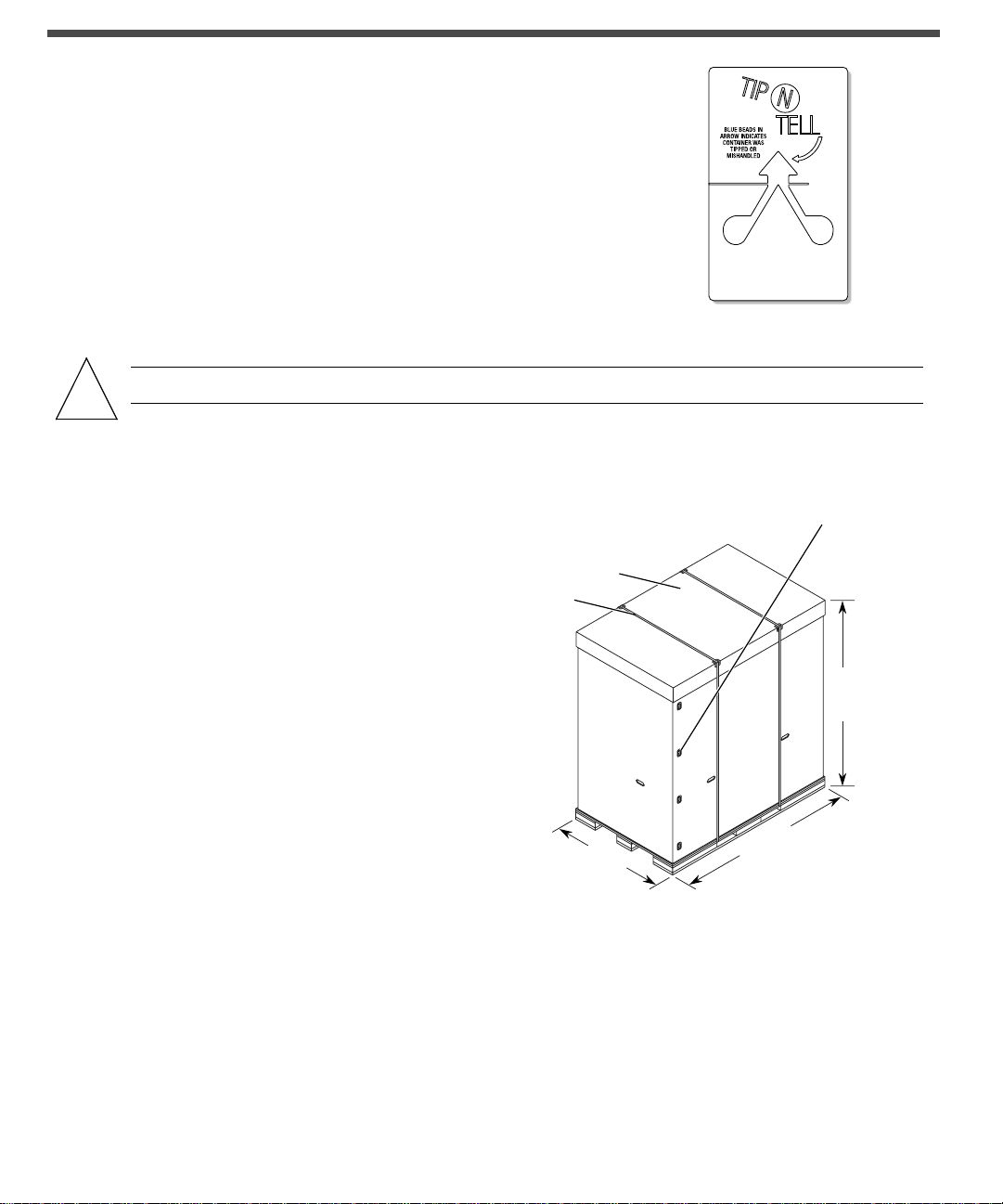
1. Verify the container was not damaged during shipment. Review
the
TIP N TELL device and all packaging components for
indications of rough treatment. If damage is evident, note on
airbill or bill of lading. Failure to note damage may invalidate
future claims. Noting possible damage allows the claimant time
to file a claim with the shipping carrier.
Caution – Use a 60-inch pallet jack (suggested) to transport the container.
!
2. Prepare cutting pliers, or equivalent, to remove
plastic banding on outside of shipping
container. A minimum of 18 ft [5.49 meters] of
floor space is required to unload the cabinet.
The cabinet may be unloaded from either end
of the pallet. Ramps are attach to either end of
the pallet. Note the “RAMPS ATTACH THIS
END” markings and image on the outside of
the shipping carton when considering its
permanent location. The shipping label on the
carton indicates the front of the unit.
Carton
top cap
Banding
Locking
clips
Height:
80.75 inches
(2051.1 mm)
3. Position the shipping container as close as
possible to the final installation site. Access to
all sides of the cabinet is needed with a
minimum of 18 ft (5.49 m) to move the cabinet
from the pallet, down the ramp, and onto the
floor.
4. Cut the outer banding and remove the carton
top cap. Remove the eight plastic locking clips
(four per side) by squeezing the center flanges
together while pulling outward.
5. Remove outer cartons. Remove the hardware box located at the front or rear of the system and the two
shipping kit boxes located on the sides of the pallet deck. Take out the 9/16-inch open-end wrench from
the hardware box, and retain the remaining items for later use as needed.
48 inches
(1219.2 mm)
Front
Side
75.5 inches
(1917.7 mm)
Page 3

6. Remove internal top cap. Remove the two ramps from each side of the pallet deck and set aside for
later use.
External
carton top
Internal
top cap
Plastic
bag
Ramps
Hardware
box
7. Remove the customer service documentation from the shipping kit box. Customer service
documentation consists of the system overview, site planning guide, hardware installation and deinstallation guide, service manual, and additional configuration information.
Caution – To prevent damage during installation, remove the four doors from the cabinet before
you remove the unit from the pallet. Use the edges of the cabinet frame to maneuver the cabinet.
!
Do not use the internal system board handles to move the cabinet.
Shipping kit boxes
Outer cartons
8. Remove the front and rear chocks. Remove the outer plastic bag. Remove the doors from the front and
rear of the cabinet by pulling down on the top spring-loaded hinge pins, and then lift the doors upward
to remove from the pins on the bottom hinge brackets of the cabinet. Set the four doors aside.
Caution – To prevent damage to the kick plate mounting bracket assembly, remove the kick plate
from both ends of the cabinet prior to unloading. The cabinet cannot be moved at an angle of more
than 10 degrees maximum.
!
9. Remove the kick plate assemblies at the front and rear of the cabinet. Use a pull-turn motion to release
the spring-loaded captive locking pin and pull the kick plate and mounting tube outward from the
mounting bracket and set aside. Loosen the two captive panel fasteners of the kick plate mounting
bracket assembly. Remove by pulling forward and tipping downward to release the support tabs from
their mounting holes.
Page 4

10. Return a chock to the pallet end used for unloading.
11. At the end of the pallet not used for unloading,
use the 9/16-inch open-end wrench to remove
the four bolts from the two zinc-plated
shipping brackets. Retain the parts for later
use.
12. Return the remaining chock to its original position on the pallet deck.
Chock
Kick plate
assembly
Caution – Ensure Step 12 is completed before proceeding. Both chocks should be installed at
!
this time.
13. Align the tines of the ramps with corresponding holes at the unloading side of the pallet. Verify the
ramps are firmly in position by pressing or standing on the back side of the tines.
14. At the unloading side of the pallet where the ramps are attached, remove the chock. Using the 9/16 inch
open-end wrench, remove the four bolts from the two zinc-plated shipping brackets. Retain the parts
for later use.
15. Move the cabinet off the pallet. One or
two persons should push while two
others slowly guide the cabinet down the
ramps. Maneuver the cabinet using the
edges of the cabinet frame. Do not use the
internal handles to move the cabinet.
Shipping bolts
and brackets
!
Caution – Refer to the Sun Fire 15K/12K Systems Site Planning Guide for air-cooling requirements for
raised-floor computer room environments.
Page 5

16. Move the cabinet to the position where it will
be installed. Fully extend the four leveling feet
at the base of each corner of the cabinet. Make
an additional 1/4 turn of the leveling feet to
ensure stability.
17. After the cabinet has been positioned in its
permanent location, re-install the two kick plate
assemblies. Insert the inner support tabs of the
kick plate mounting bracket. Align the two
outer tabs at the front mounting holes of the
cabinet frame and slide the bracket inward to
align the inner support tabs into the two
mounting holes of the horizontal support
structure under the cabinet. Secure with the two
captive panel fasteners. Re-insert the square
mounting tube of the kick plate mounting
bracket assembly until it is flush with the
cabinet. Secure with the spring-loaded captivelocking pin.
18. Use a Phillips No. 2 screwdriver to loosen the
four captive screws on the front handle bar and
the four captive screws on the rear handle bar.
Remove and retain these parts for later use.
19. Reinstall the front and rear cabinet doors by
inserting each door onto the bottom peg for
each bottom-hinge bracket of the cabinet. At the
top of each door, pull down the spring-loaded
pin and insert the peg of the door into the tophinge bracket of the cabinet.
Note – Shipping materials cannot be reused due to foam compression. These materials can be disposed of per
the customer’s instructions. Reduce and recycle whenever possible.
20. Refer to the Sun Fire 15K/12K Systems Hardware Installation and De-Installation Guide and the other
customer service documentation that was removed in Step 7.
Page 6

Accessing Sun Documentation
You can view, print, or purchase a broad selection of Sun documentation, including localized versions, at:
http://www.sun.com/documentation
Contacting Sun Technical Support
If you have technical questions about this product that are not answered in this document, go to:
http://www.sun.com/service/contacting
Sun Welcomes Your Comments
Sun is interested in improving its documentation and welcomes your comments and suggestions. You can
submit your comments by going to:
http://www.sun.com/hwdocs/feedback
Please include the title and part number of your document with your feedback:
Sun Fire 15K/12K Systems Unpacking Guide, part number 806-3508-12
Copyright2003 SunMicrosystems,Inc. Allrights reserved.Use is subjectto licenseterms. Third-partysoftware, including fonttechnology,is copyrighted andlicensed from Sun
suppliers.Portions may be derivedfrom Berkeley BSD systems,licensed fromU.of CA. Sun,Sun Microsystems,the Sun logo,SunFire, and Solaris are trademarksor registered
trademarks of SunMicrosystems, Inc. inthe U.S. andin other countries.All SPARCtrademarks areused under licenseand are trademarksor registeredtrademarks of SPARC
International, Inc. inthe U.S.andin othercountries. Government users aresubject to theSunMicrosystems, Inc. standardlicenseagreement and applicableprovisionsof the FAR and
itssupplements.
Copyright 2003 SunMicrosystems, Inc.Tous droitsréservés. Distr ibué pardes licences quien restreignentl’utilisation. Le logicieldétenu par destiers, et quicomprend la
technologie relative auxpolices de caractères,est protégé parun copyright etlicencié par desfournisseurs deSun. Des parties de ceproduit pourront êtredérivées dessystèmes
BerkeleyBSD licenciéspar l’Université deCalifornie.Sun, SunMicrosystems,le logoSun, Sun Fire,et Solaris sontdes marquesde fabrique oudes marques déposéesde Sun
Microsystems,Inc. auxEtats-Unis et dansd’autres pays. Toutes les marquesSPARC sont utiliséessous licenceet sont desmarques de fabriqueou desmarques déposées de
SPARC International,Inc. aux Etats-Uniset dansd’autres pays.
Sun Microsystems, Inc.
4150 Network Circle
Santa Clara, CA 95054 USA
www.sun.com
Part No. 806-3508-12, Rev.A
June 2003
 Loading...