

Page 1

TM
Sun StorEdge L25 Tape Library
TM
and Sun StorEdge L100 Tape Library
Installation Guide
Introduction 3
Site Requirements 3
Space Requirements......................................................................................3
Cooling Considerations................................................................................4
Environmental Requirements......................................................................5
Power and Grounding..................................................................................5
Installing a Desktop or Deskside Library 6
Installing a Desktop L25 Library.................................................................6
Installing a Deskside L100 Library .............................................................6
Installing a Rack Mount Library 7
Determining the Position of the Shelves in the Rack...............................7
Installing the Rack Mount Shelves..............................................................8
Installing the Library in the Rack..............................................................15
Installing Drives in the Library 18
Installing Tape Drives in an L25 ...............................................................18
Installing Tape Drives in an L100 .............................................................19
Document 6423015-01, Ver. 1, Rel. 0, June 2002 1
Page 2

Sun StorEdge™ L25 Tape Library and Sun StorEdge™ L100 Tape Library Installation Guide
Document 6423015-01, Ver. 1, Rel. 0
June 2002
Preparing and Inserting Tape Cartridges 22
Labeling Tape Cartridges ..........................................................................22
Setting the Write-Protect Switch...............................................................23
Placing Cartridges in the Library ............................................................. 25
Connecting the Library to AC Power 29
L25 Power Requirements...........................................................................29
L100 Power Requirements.........................................................................32
Connecting the Library to the Host Computer 34
SCSI Cabling Guidelines............................................................................ 34
Terminator Power.......................................................................................34
SCSI Cabling Diagrams..............................................................................35
Powering Up the Library 36
Disabling Unused Drive Bays 39
2 6207947-04fN 20
Page 3

Sun StorEdge™ L25 Tape Library and Sun StorEdge™ L100 Tape Library Installation Guide
Document 6423015-01, Ver. 1, Rel. 0
June 2002
Introduction 0
This document explains how to install a stand-alone Sun StorEdge™
L25 Tape Library or Sun StorEdge™ L100 Tape Library. Hereafter in
this document, these libraries will be referred to as the L25 and the
L100, respectively.
Note: To install an L25 or L100 library module in a multiple library
stack, refer to the StackLink Installation Instructions
(PN 6423029).
Site Requirements 0
Space Requirements 0
Table 1 Library
Dimensions
When selecting an installation site for the library, consider the
following requirements:
• Space Requirements
• Cooling Considerations
• Environmental Requirements
• Power and Grounding
Tabl e 1
lists the dimensions of the L25 and L100 libraries.
Caution: Allow at least 5 inches (12.7 cm) of space behind the
library to allow proper ventilation.
L25 L100
Height
Width
6.9 in. (176 mm) 23.4 in. (595 mm)
19 in. (482 mm) 19 in. (482 mm)
Depth
28.6 in. (726 mm) 28.6 in. (726 mm)
Introduction 3
Page 4
Sun StorEdge™ L25 Tape Library and Sun StorEdge™ L100 Tape Library Installation Guide
Vent
Document 6423015-01, Ver. 1, Rel. 0
June 2002
Cooling Considerations
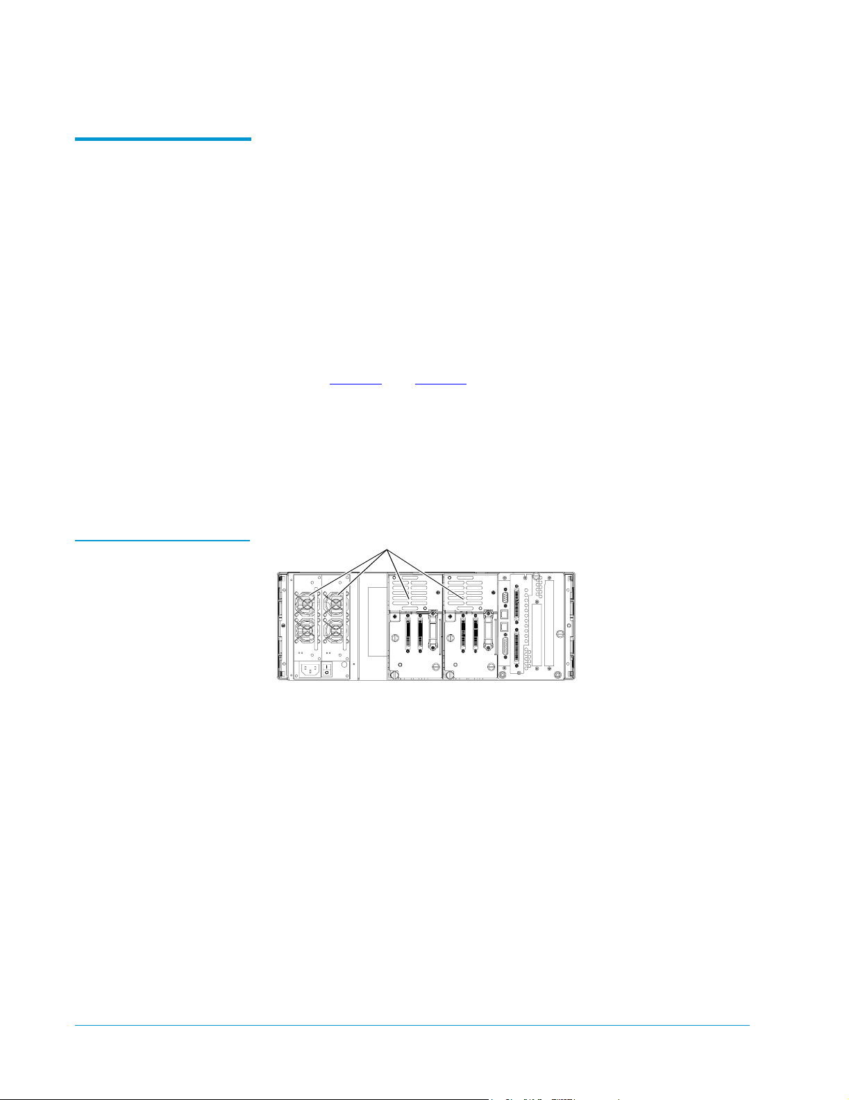
Figure 1 Vent Locations,
L25
Cooling is one of the most important factors to consider when selecting
0
a location for the library. The L25 and L100 libraries are force-cooled:
air is drawn into the library through vents at the lower edge of the
front bezel and exhausted through vents at the back of the library. To
ensure that the library is adequately ventilated:
• Place the library on a hard, level surface, or in a standard 19-inch
rack.
• If the library will be placed in a rack, the rack must be open or
ventilated so that the air temperature behind the library at the air
outlets is less than 104°F (40°C).
• Verify that no cables obstruct the vents at the back of the library
(see figure 1
and figure 2).
• Verify that nothing obstructs the vents at the lower edge of the
front bezel.
• Allow at least 5 inches (12.7 cm) of space behind the library or rack.
• Do not install the library near a heater or radiator which could
warm the air drawn into the library.
s
4 Site Requirements
Page 5
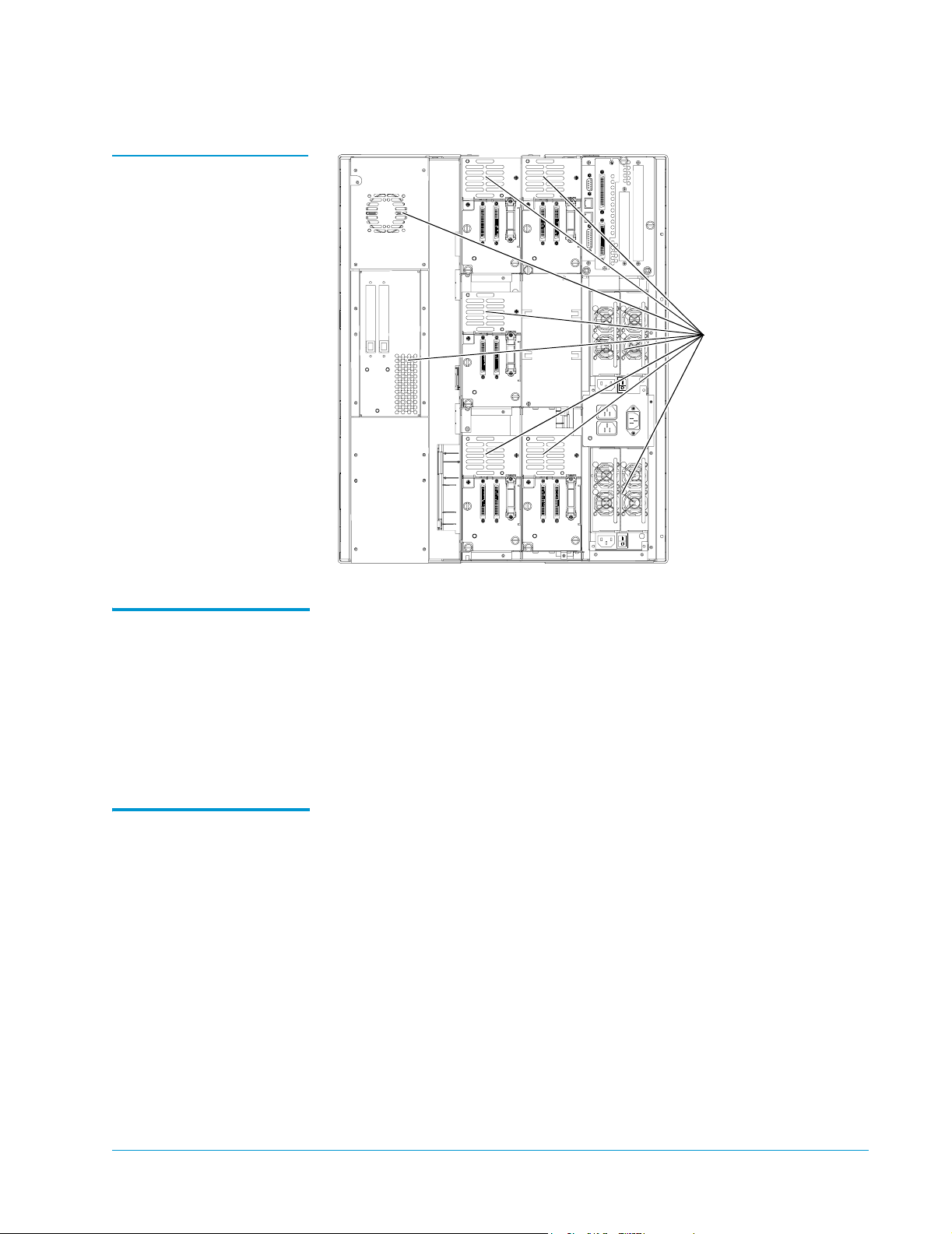
Figure 2 Vent Locations,
L100
Sun StorEdge™ L25 Tape Library and Sun StorEdge™ L100 Tape Library Installation Guide
Document 6423015-01, Ver. 1, Rel. 0
June 2002
Vents
Environmental Requirements
Power and Grounding
The installation site (desktop or deskside library) or the interior of the
0
rack (rack mount library) must meet the following environmental
requirements:
• Humidity: 20% to 80%, non-condensing
• Temperature: 50°F to 104°F (10°C to 40°C)
• Altitude: -100 to +10,000 feet (-30 to +3,000 meters)
The L25 and L100 power supplies accept 88 VAC to 264 VAC input
0
power at 47 Hz to 63 Hz.
The library must be connected to a grounded power outlet. If the
library is mounted in a rack, the rack must also be grounded.
Site Requirements 5
Page 6

Sun StorEdge™ L25 Tape Library and Sun StorEdge™ L100 Tape Library Installation Guide
Document 6423015-01, Ver. 1, Rel. 0
June 2002
Installing a Desktop or Deskside Library 0
This section explains how to install a desktop L25 library or a deskside
L100 library. To install a rack mount library, see Installing a Rack
Mount Library.
Note: The procedures in this section assume that you have already
unpacked the library. If you have not, do so now, referring to
the Sun StorEdge™ L25 Tape Library Unpacking Instructions
(PN 6421029) or the Sun StorEdge™ L100 Tape Library
Unpacking Instructions (PN 6423014).
Installing a Desktop L25 Library
Installing a Deskside L100 Library
To install a desktop L25:
0
1 Convert the L25 to a desktop unit by performing the procedures
detailed in the Sun StorEdge™ L25 Tape Library Rack Mount to
Desktop Conversion Instructions (PN 6421032).
This document is provided with the Sun StorEdge™ L25 Tape
Library Rack Mount to Desktop Conversion Kit.
2 Place the library in the installation location, preferably on a sturdy
desk or tabletop.
3 Proceed to Installing Drives in the Library on page 18 to continue
the installation procedure.
To install a deskside L100:
0
1 Convert the L100 to a deskside unit by performing the procedures
detailed in the Sun StorEdge™ L100 Tape Library Rack Mount to
Deskside Conversion Instructions (PN 6423027).
This document is provided with the Sun StorEdge™ L100 Tape
Library Rack Mount to Deskside Conversion Kit.
2 Place the library in the installation location.
3 Proceed to Installing Drives in the Library on page 18 to continue
the installation procedure.
6 Installing a Desktop or Deskside Library
Page 7
Sun StorEdge™ L25 Tape Library and Sun StorEdge™ L100 Tape Library Installation Guide
Document 6423015-01, Ver. 1, Rel. 0
June 2002
Installing a Rack Mount Library 0
This section explains how to install an L25 or L100 library in a
standard 19-inch rack.
Note: The procedures in this section assume that you have already
unpacked the library. If you have not, do so now, referring to
the Sun StorEdge™ L25 Tape Library Unpacking Instructions
(PN 6421029) or the Sun StorEdge™ L100 Tape Library
Unpacking Instructions (PN 6423014).
Determining the Position of the Shelves in the Rack
Before starting the rack mount installation:
0
1 Determine the proper position of the shelves in the rack:
Caution: Take rack stability into account when determining
where to place the library in the rack.
• An L25 library uses 4U of vertical space.
• An L100 library uses 13.5U of vertical space.
• The StackLink mounting hardware uses 1U of vertical space at
the top of the rack, and either 1U or .5U at the bottom of the
rack (see the StackLink Installation Instructions, PN 6423029, for
more information).
Note: 1U equals 1.75 inches (44.45 millimeters).
2 Use a pencil to mark the desired shelf position on the rack rails.
Installing a Rack Mount Library 7
Page 8

Sun StorEdge™ L25 Tape Library and Sun StorEdge™ L100 Tape Library Installation Guide
Document 6423015-01, Ver. 1, Rel. 0
June 2002
Installing the Rack Mount Shelves
Table 2 Rack Mount Kit
Contents
This section explains how to install the rack mount shelves. You will
0
need a no. 1 POZIDRIV
Checking the Contents of the Rack Mount Kit 0
Tabl e 2
lists the contents of the rack mount kit.
Part No. Description Qty.
217395 Shelf, right 1
217396 Shelf, left 1
217397 Front shelf clamp 4
217405 Clamp strip 2
217406 Clamp washer 12
YS40986 M4 x 10 countersink screw 8
YS42086 No. 10 UNF x 3/8" countersink screw 12
®
screwdriver for this procedure.
Installing the Shelves in a Half U Position 0
To install the rack mount shelves in a half U position:
Note:
In half U position, the bottom of the rack mount shelf lines
up with the middle of a U.
1 Position the left shelf in the rack, aligning the bottom of the shelf
with the pencil marking you made in step 2
2 Use six screws (PN YS42086) and washers (PN 217406) to secure
the shelf to the rack rails as shown in figure 3
Note: Do not tighten these screws fully; you will finish
on page 7.
.
tightening them later in this procedure.
3 Repeat steps 1 and 2 to install the right shelf.
8 Installing a Rack Mount Library
Page 9
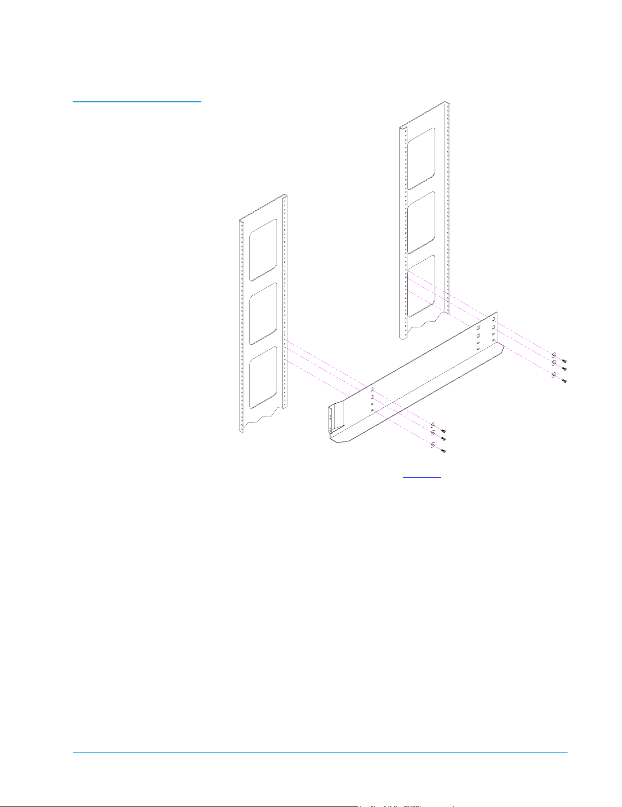
Figure 3 Securing the
Shelf in the Half Position
Sun StorEdge™ L25 Tape Library and Sun StorEdge™ L100 Tape Library Installation Guide
Document 6423015-01, Ver. 1, Rel. 0
June 2002
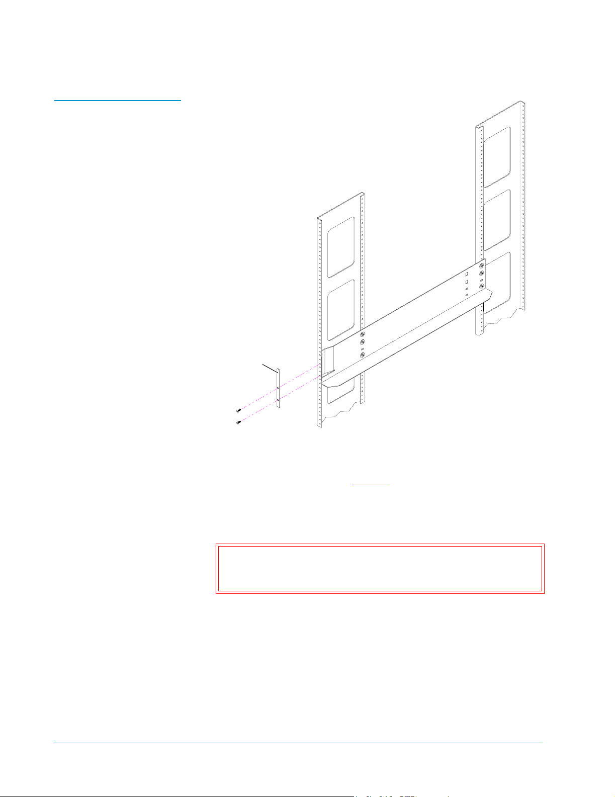
4 Install the front shelf clamps (see figure 4):
a Position a front shelf clamp (PN 217397) on the front left rack
rail.
b Secure the shelf clamp to the rack rail using two countersink
screws (PN YS40986).
c Repeat these steps to install a shelf clamp on the front right
rack rail.
Installing a Rack Mount Library 9
Page 10
Sun StorEdge™ L25 Tape Library and Sun StorEdge™ L100 Tape Library Installation Guide
Document 6423015-01, Ver. 1, Rel. 0
June 2002
Figure 4 Installing the
Front Shelf Clamps
Front
shelf clamp
5 Fully tighten the screws securing the right and left shelves to the
rack rails.
6 Install the clamp strips (see figure 5):
a Position a front shelf clamp (PN 217397) at the front of the front
left rack rail, with the bottom of the clamp approximately 9U
above the bottom of the rack mount shelf.
Caution: The top of the front shelf clamp must be no more
than 22.75 in. (580 mm) above the bottom of the rack
mount shelf.
10 Installing a Rack Mount Library
Page 11
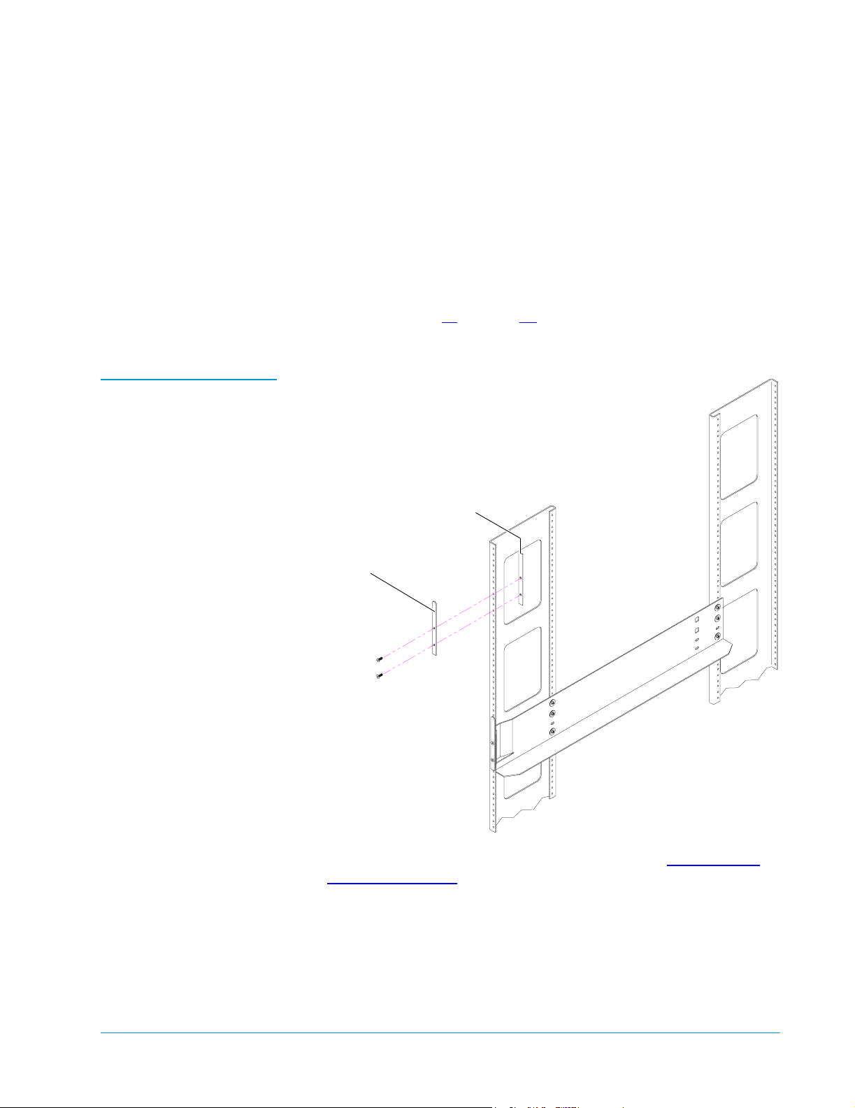
Figure 5 Installing the
Clamp Strips
Sun StorEdge™ L25 Tape Library and Sun StorEdge™ L100 Tape Library Installation Guide
Document 6423015-01, Ver. 1, Rel. 0
June 2002
b Position a clamp strip (PN 217405) behind the front left rack
rail, aligning it with the front shelf clamp.
c Insert a screw (PN YS40986) through the upper hole in the
front shelf clamp, through the rack rail, and into the upper hole
in the clamp strip.
d Insert a screw (PN YS40986) through the bottom hole in the
front shelf clamp, through the rack rail, and into the bottom
hole in the clamp strip.
e Repeat steps 6a through 6d to install the front shelf clamp and
clamp strip on the right rack rail.
Clamp strip
Front shelf clamp
The shelf installation is now complete. Proceed to Installing the
Library in the Rack on page 15 to install the library.
Installing a Rack Mount Library 11
Page 12
Sun StorEdge™ L25 Tape Library and Sun StorEdge™ L100 Tape Library Installation Guide
Document 6423015-01, Ver. 1, Rel. 0
June 2002
Installing the Shelves in a Full U Position 0
To install the rack mount shelves in a full U position:
Note: In full U position, the bottom of the rack mount shelf lines
up with the bottom of a U.
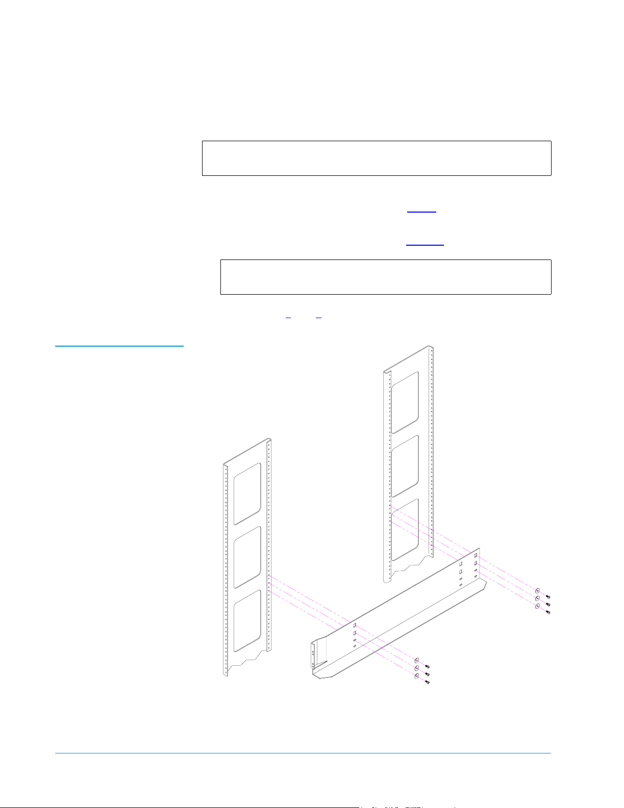
1 Position the left shelf in the rack, aligning the bottom of the shelf
with the pencil marking you made in step 2
2 Use six screws (PN YS42086) and washers (PN 217406) to secure
the shelf to the rack rails as shown in figure 6
Note: Do not tighten these screws fully; you will finish
tightening them later in this procedure.
3 Repeat steps 1 and 2 to install the right shelf.
on page 7.
.
Figure 6 Securing the
Shelf in the Half Position
12 Installing a Rack Mount Library
Page 13
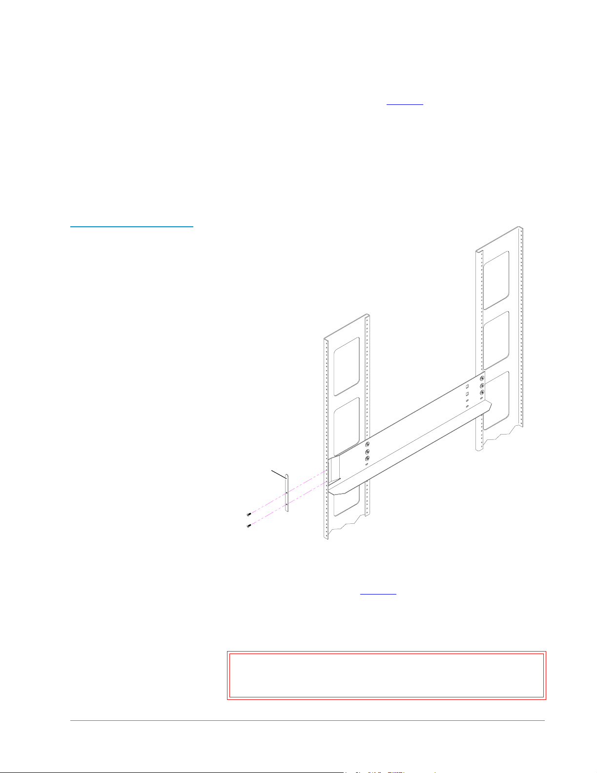
Figure 7 Installing the
Front Shelf Clamps
Sun StorEdge™ L25 Tape Library and Sun StorEdge™ L100 Tape Library Installation Guide
Document 6423015-01, Ver. 1, Rel. 0
June 2002
4 Install the front shelf clamps (see figure 7):
a Position a front shelf clamp (PN 217397) on the front left rack
rail.
b Secure the shelf clamp to the rack rail using two countersink
screws (PN YS40986).
c Repeat these steps to install a shelf clamp on the front right
rack rail.
Front
shelf clamp
5 Fully tighten the screws securing the right and left shelves to the
rack rails.
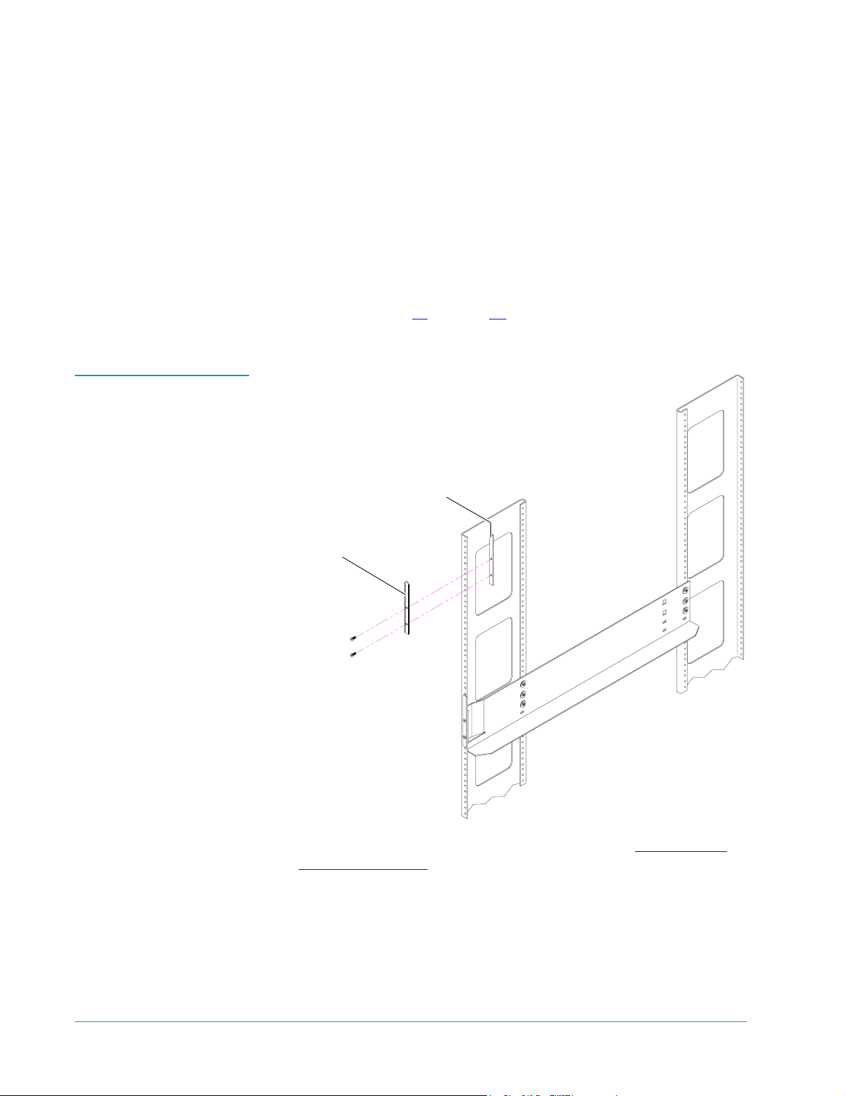
6 Install the clamp strips (see figure 8):
a Position a front shelf clamp (PN 217397) at the front of the front
left rack rail, with the bottom of the clamp approximately 9U
above the bottom of the rack mount shelf.
Caution: The top of the front shelf clamp must be no more
than 22.75 in. (580 mm) above the bottom of the rack
mount shelf.
Installing a Rack Mount Library 13
Page 14
Sun StorEdge™ L25 Tape Library and Sun StorEdge™ L100 Tape Library Installation Guide
Document 6423015-01, Ver. 1, Rel. 0
June 2002
b Position a clamp strip (PN 217405) behind the front left rack
rail, aligning it with the front shelf clamp.
c Insert a screw (PN YS40986) through the upper hole in the front
shelf clamp, through the rack rail, and into the upper hole in
the clamp strip.
d Insert a screw (PN YS40986) through the bottom hole in the
front shelf clamp, through the rack rail, and into the bottom
hole in the clamp strip.
e Repeat steps 6a through 6d to install the front shelf clamp and
clamp strip on the right rack rail.
Figure 8 Installing the
Clamp Strips
Clamp strip
Front shelf clamp
The shelf installation is now complete. Proceed to Installing the
Library in the Rack to install the library.
14 Installing a Rack Mount Library
Page 15
Sun StorEdge™ L25 Tape Library and Sun StorEdge™ L100 Tape Library Installation Guide
Document 6423015-01, Ver. 1, Rel. 0
June 2002
Installing the Library in the Rack
This section explains how to install the library in the rack. You will
0
need a no. 2 POZIDRIV screwdriver for this procedure.
Installing an L25 Library 0
To install an L25 library in a rack:
1 Take precautions to ensure that the rack is stable:
• If you are installing the library at the top of a rack with no
equipment at the bottom of the rack, purchase a rack
stabilization kit from the rack manufacturer and install it before
installing the library.
• If you are installing the library in a rack with other equipment,
place the heaviest equipment at the bottom of the rack.
2 Verify that the rack mount shelves are level and securely fastened
to the rack.
Caution: The L25 library weighs approximately 58 lbs (26.5
kg). At least two people are required to lift and install
the library.
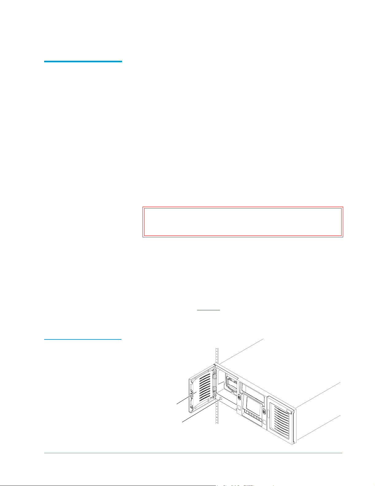
Figure 9 Securing the L25
Library to the Rack
3 With the help of another person, lift the library onto the rack
mount shelves.
4 Slide the library all the way into the rack.
5 Press the white button next to the left magazine access door and
open the door.
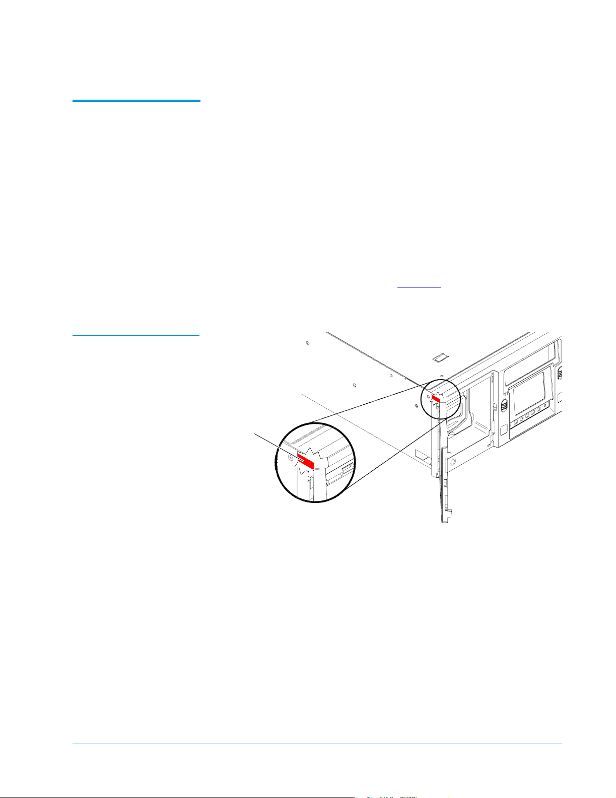
6 Notice the hole behind the magazine access door, at the lower edge
of the library (see figure 9
).
This hole provides access to the rack mount clamp screw.
Magazine
access door
Access hole for
rack mount
clamp screw
Installing a Rack Mount Library 15
Page 16

Sun StorEdge™ L25 Tape Library and Sun StorEdge™ L100 Tape Library Installation Guide
Document 6423015-01, Ver. 1, Rel. 0
June 2002
7 Insert a no. 2 POZIDRIV screwdriver into the hole and turn the
rack mount clamp screw clockwise to tighten it.
Caution: Do not over-tighten the rack mount clamp screw.
When the screw begins to feel tight, turn it an
additional quarter turn and then stop.
As you tighten this screw, a lever protrudes from the side of the
library and presses against the back side of the rack rail.
8 Repeat steps 5 through 7 to secure the right side of the library to the
rack.
9 Close the magazine access doors.
Proceed to Installing Drives in the Library
on page 18 to continue
the installation procedure.
Installing an L100 Library 0
To install an L100 library in a rack:
Warning: The L100 library weighs approximately 162 lbs (74 kg).
At least two people are required to lift and install the
library.
1 Take precautions to ensure that the rack is stable:
• If you are installing the library at the top of a rack with no
equipment at the bottom of the rack, purchase a rack
stabilization kit from the rack manufacturer and install it before
installing the library.
• If you are installing the library in a rack with other equipment,
place the heaviest equipment at the bottom of the rack.
2 Verify that the rack mount shelves are level and securely fastened
to the rack.
3 With the help of another person, lift the library onto the rack
mount shelves.
4 Slide the library all the way into the rack.
5 Press the two white buttons next to the left magazine access doors
and open the doors.
6 Notice the two holes behind the left magazine access doors (see
figure 10
).
These holes provide access to the rack mount clamp screws.
16 Installing a Rack Mount Library
Page 17
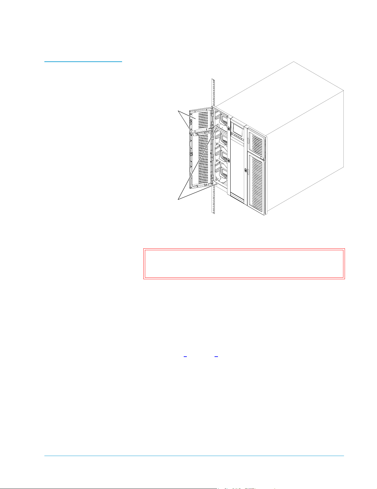
Figure 10 Securing the
Library to the Rack
Sun StorEdge™ L25 Tape Library and Sun StorEdge™ L100 Tape Library Installation Guide
Document 6423015-01, Ver. 1, Rel. 0
June 2002
Magazine
access doors
Access holes
for the rack
mount clamp
screws
7 Insert a no. 2 POZIDRIV screwdriver into one of the holes and turn
the rack mount clamp screw clockwise to tighten it fully.
Caution: Do not overtighten the rack mount clamp screw.
When the screw begins to feel tight, turn it an
additional quarter turn and then stop.
As you tighten this screw, a lever protrudes from the side of the
library and presses against the back side of the rack rail.
8 Tighten the remaining rack mount clamp screw in the same
manner.
9 Press the white button next to the right magazine access door.
The right magazine access door opens.
10 Repeat steps 6 through 8 to secure the right side of the library to
the rack.
11 Close the magazine access doors.
Installing a Rack Mount Library 17
Page 18
Sun StorEdge™ L25 Tape Library and Sun StorEdge™ L100 Tape Library Installation Guide
Document 6423015-01, Ver. 1, Rel. 0
June 2002
Installing Drives in the Library 0
Installing Tape Drives in an L25
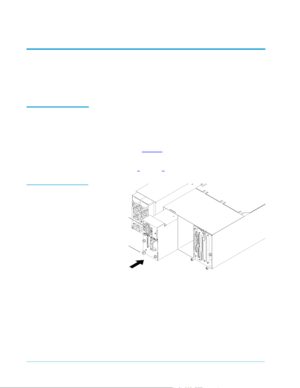
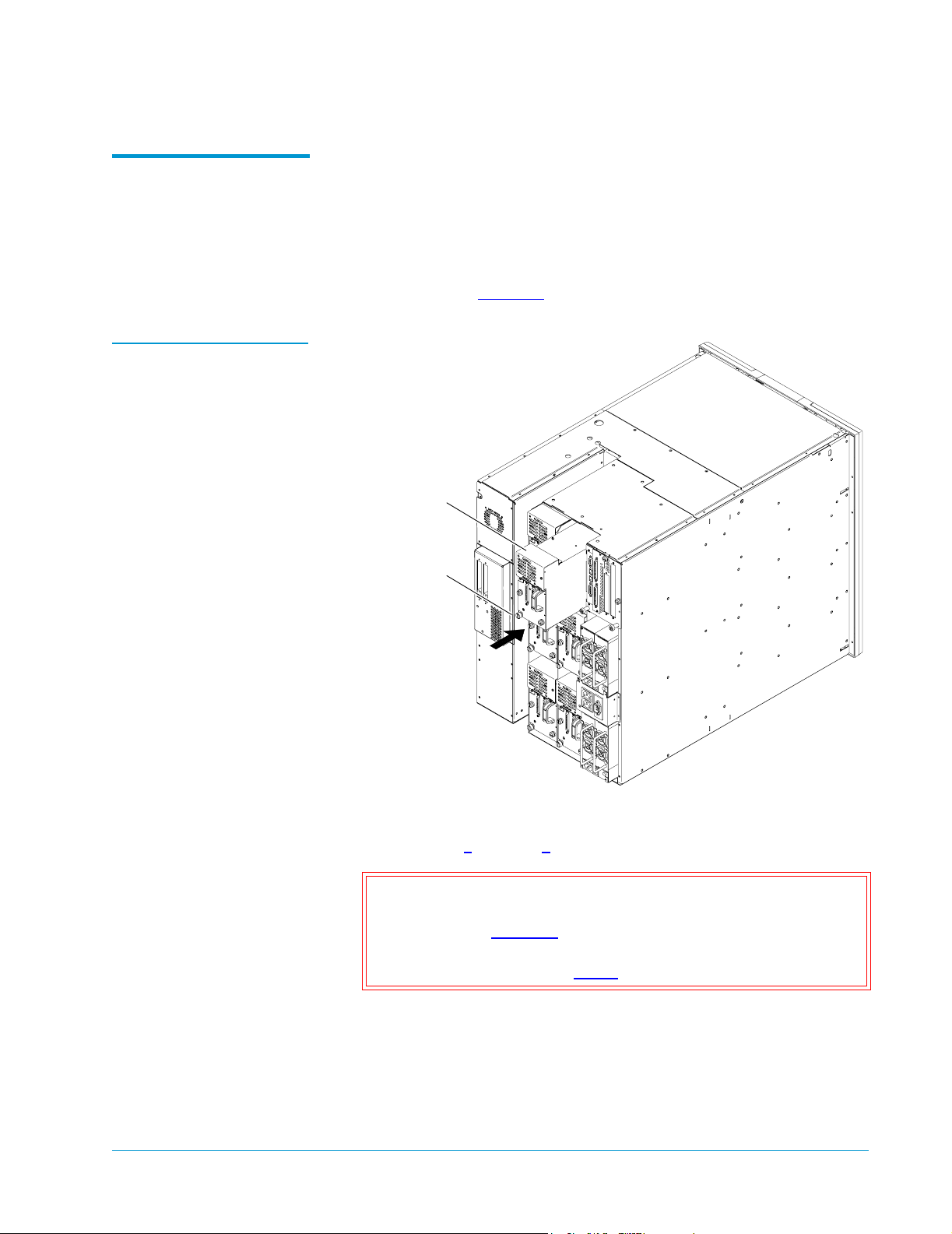
Figure 11 Installing a Tape
Drive in an L25 Library
This section explains how to install tape drives in the library. You will
®
need a TORX
T-20 screwdriver and a flat blade screwdriver for this
procedure.
To install tape drives in an L25:
0
1 At the back of the library, use a TORX T-20 screwdriver to remove
the cover plate protecting the drive bay in which you will install
the tape drive.
2 Insert the tape drive into the drive bay slowly until the connectors
are seated (see figure 11
3 Tighten the tape drive thumbscrew using a flat blade screwdriver.
4 Repeat steps 1 through 3 to install another tape drive, if desired.
Tape drive
).
Thumbscrew
18 Installing Drives in the Library
Page 19
Sun StorEdge™ L25 Tape Library and Sun StorEdge™ L100 Tape Library Installation Guide
Document 6423015-01, Ver. 1, Rel. 0
June 2002
Installing Tape Drives in an L100
Figure 12 Installing a Tape
Drive in an L100 Library
To install tape drives in an L100:
0
1 At the back of the library, use a TORX T-20 screwdriver to remove
the cover plate protecting the drive bay in which you will install
the tape drive.
2 Insert the tape drive into the drive bay slowly until the connectors
are seated (see figure 12
Tape drive
Thumbscrew
).
3 Tighten the tape drive thumbscrew using a flat blade screwdriver.
4 Repeat steps 1 through 3 to install any additional tape drives.
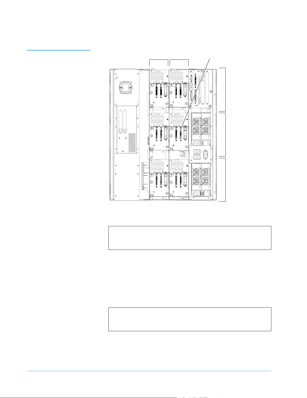
Caution: If you are installing fewer than six drives in an L100
library, do not install a drive in drive bay 1 on level 2
(see figure 13
). Installing a drive in this location
reduces the cartridge capacity of the library (see the
Note following step 5.
Installing Drives in the Library 19
Page 20
Sun StorEdge™ L25 Tape Library and Sun StorEdge™ L100 Tape Library Installation Guide
Document 6423015-01, Ver. 1, Rel. 0
June 2002
Figure 13 Drive Bay
Numbering, L100
Drive bay
column 2
Drive bay
column 1
Leave this drive bay empty unless
you are installing a sixth drive
Level 1
Level 2
Level 3
5 If you installed six tape drives, remove the level 3 left magazine
and fixed slot as follows:
Note: The level 3 left magazine and fixed slot prevent the
robotic hand from accessing the tape drive in drive bay 1
on level 2 of the library.
a Press the white buttons next to the two left magazine access
doors.
The magazine access doors open.
b Remove the level 3 left magazine by grasping the handle at the
front of the magazine and sliding it forward and out of the
library.
Note: Library levels are numbered from top to bottom. The
level 3 left magazine is the left magazine that is third
from the top of the library.
20 Installing Drives in the Library
Page 21
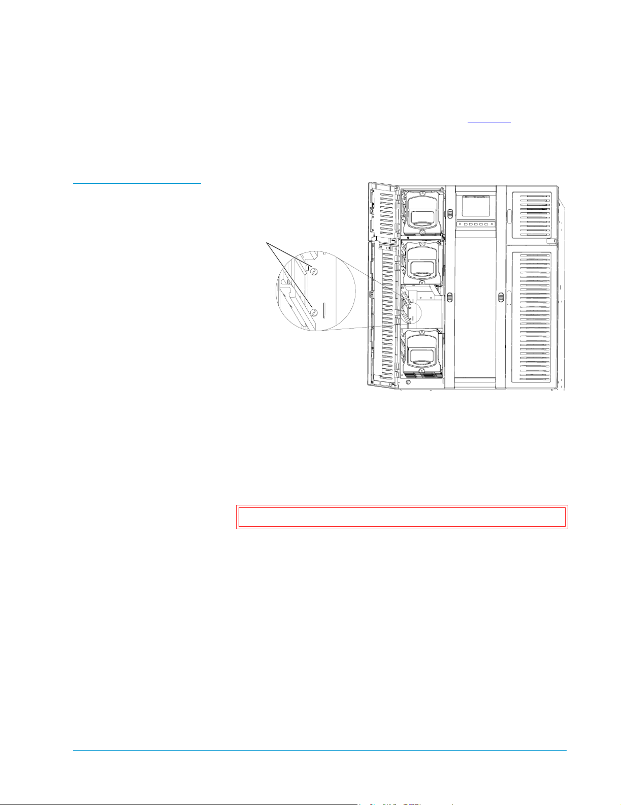
Figure 14 Loosening the
Captive Screws
Sun StorEdge™ L25 Tape Library and Sun StorEdge™ L100 Tape Library Installation Guide
Document 6423015-01, Ver. 1, Rel. 0
June 2002
c Using a flat blade screwdriver, loosen the two captive screws
that hold the level 3 fixed slot in place (see figure 14
).
The captive screws spring forward slightly when they are fully
loosened.
Captive screws
d Reach into the library and carefully move the hand assembly to
the right front of the library, away from the fixed slot.
e Reach into the level 3 magazine slot and grasp the right side of
the level 3 fixed slot.
f Gently pull the fixed slot to the right and remove it from the
library.
Caution: Do not replace the level 3 left magazine.
g Close the magazine access doors.
Installing Drives in the Library 21
Page 22

Sun StorEdge™ L25 Tape Library and Sun StorEdge™ L100 Tape Library Installation Guide
Document 6423015-01, Ver. 1, Rel. 0
June 2002
Preparing and Inserting Tape Cartridges 0
This section explains how to insert tape cartridges into the L25 and
L100 libraries. This procedure consists of the following steps:
• Labeling the tape cartridges
• Setting the write-protect switch
• Placing cartridges in the library
Labeling Tape Cartridges
Table 3 Bar Code Label
Requirements
Attaching a bar code label to each cartridge enables the library to
0
identify tape cartridges quickly, speeding the inventory process.
Note: The L25 and L100 libraries are capable of reading most
common bar code formats.
Bar Code Label Requirements 0
Bar code labels must meet the requirements of the latest revision of the
ANSI MH10.8M standard, and should use industry standard Code 39
(3 of 9 code).
The basic requirements are listed in table 3
Label size
Quiet zone
Character height
Bar code characters
2.2 x 0.82 inches (5.59 x 2.08 cm)
0.25 inches (6.4 mm) minimum
0.3 inches (7.6 mm)
one start character, one to six alphanumeric
characters, one stop character
.
Ratio of wide to
narrow element
22 Preparing and Inserting Tape Cartridges
2.5:1 minimum
Page 23
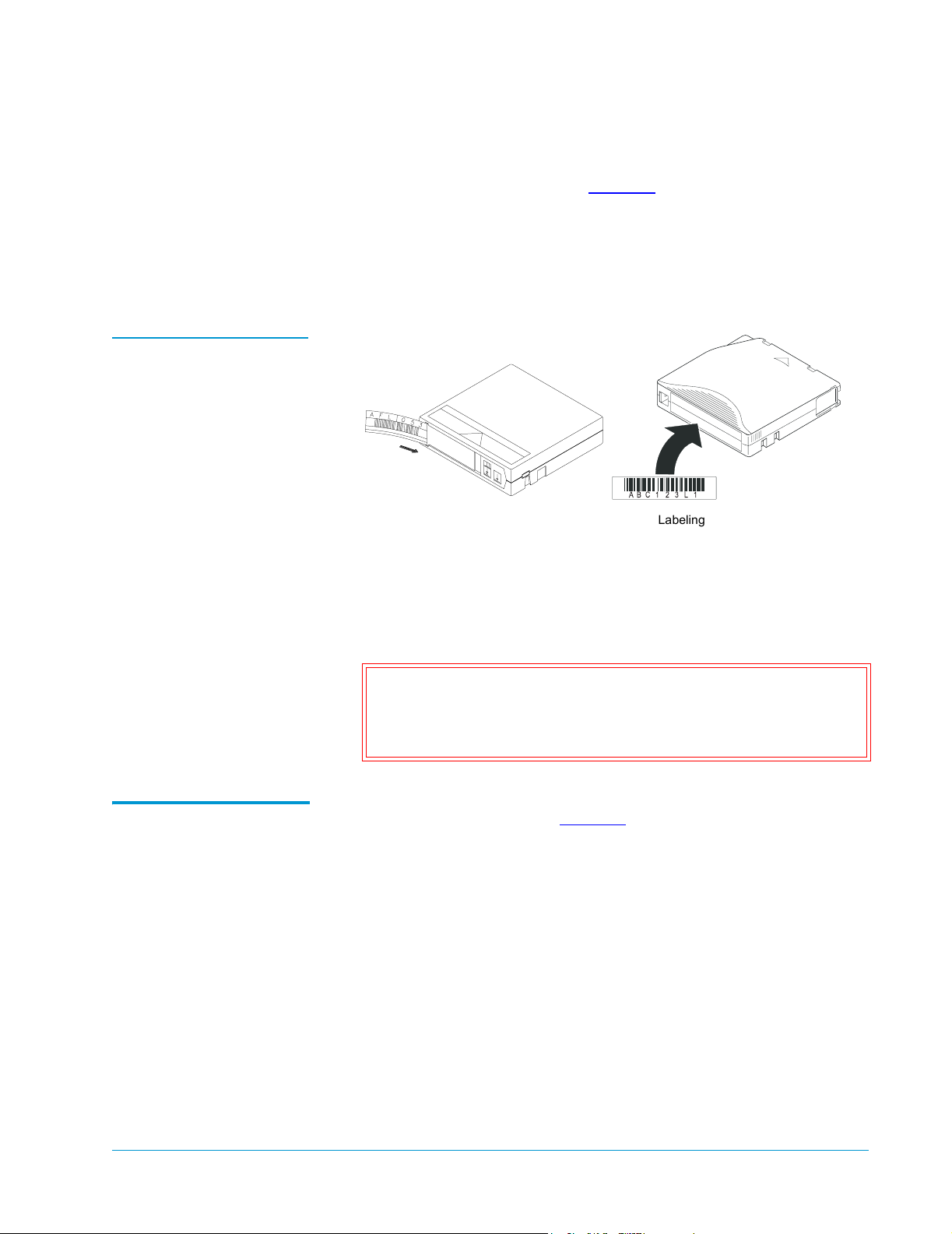
Figure 15 Labeling Tape
Cartridges
Sun StorEdge™ L25 Tape Library and Sun StorEdge™ L100 Tape Library Installation Guide
Document 6423015-01, Ver. 1, Rel. 0
June 2002
Applying the Labels 0
1 Label the tape cartridges (see figure 15):
• DLT and SDLT cartridges use non-adhesive labels that slide
into a slot at the front of the cartridge.
• LTO cartridges use adhesive labels that adhere to the front of
the cartridge.
ABC123L1
Labeling a DLT or SDLT cartridge
Labeling an LTO cartridge
Setting the WriteProtect Switch
2 Use the same method to apply a cleaning cartridge label to the
cleaning cartridge.
Cleaning cartridge labels are black and white, and their numbers
start with the letters CLN.
Caution: LTO tape drive media cannot be degaussed due to
the fact that it uses magnetic servos. Do not attempt
to degauss LTO tape drive media. If this media is
degaussed, it will no longer work.
The write-protect switch (see figure 16
0
cartridge is write-protected or write-enabled:
) controls whether the tape
• Write-protecting a cartridge protects the data it contains from
being erased or overwritten. Typically you use this setting when
removing the cartridges for storage outside the library.
• Write-enabling a cartridge allows new data to be written to the
cartridge or existing data to be modified or erased. This is the
setting that cartridges are typically set to when they are inside the
library.
Preparing and Inserting Tape Cartridges 23
Page 24
Sun StorEdge™ L25 Tape Library and Sun StorEdge™ L100 Tape Library Installation Guide
Writ
h
Document 6423015-01, Ver. 1, Rel. 0
June 2002
Setting the Write-Protect Switch (DLT and SDLT Cartridges) 0
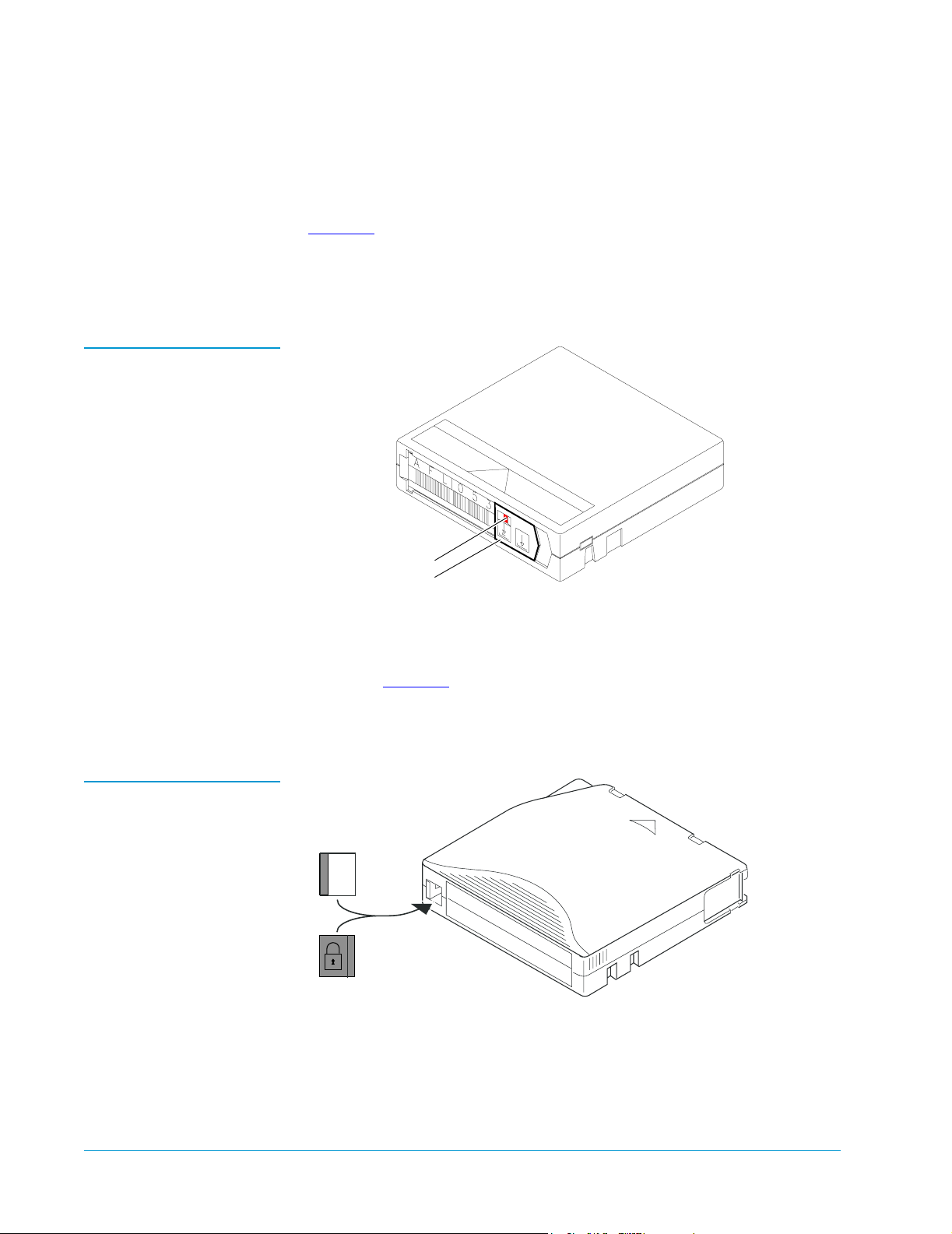
To write-protect a DLT or SDLT cartridge, move the write-protect
switch to the left. An orange tab is visible behind the switch (see
figure 16
).
To write-enable a DLT or SDLT cartridge, move the write-protect
switch to the right. The orange tab is not visible when the cartridge is
write-enabled.
Figure 16 Setting the
Write-Protect Switch (DLT
and SDLT Cartridges)
Figure 17 Setting the
Write-Protect Switch (LTO
Cartridges)
Orange tab
Write-protect switch
Setting the Write-Protect Switch (LTO Cartridges) 0
To write-protect an LTO cartridge, move the write-protect switch to the
right (see figure 17
).
To write-enable an LTO cartridge, move the write-protect switch to the
left.
e-protect switc
Slide left
Writeenabled
Writeprotected
Slide right
24 Preparing and Inserting Tape Cartridges
Page 25
Sun StorEdge™ L25 Tape Library and Sun StorEdge™ L100 Tape Library Installation Guide
Document 6423015-01, Ver. 1, Rel. 0
June 2002
Placing Cartridges in the Library
Figure 18 Magazine
Release Button
This section explains how to place tape cartridges in the library.
0
Placing Tape Cartridges in an L25 Library 0
To place tape cartridges in an L25 library:
1 Remove the left magazine:
a Press the white button next the left magazine access door and
open the door.
b Grasping the handle at the front of the left magazine, pull it
forward until it stops.
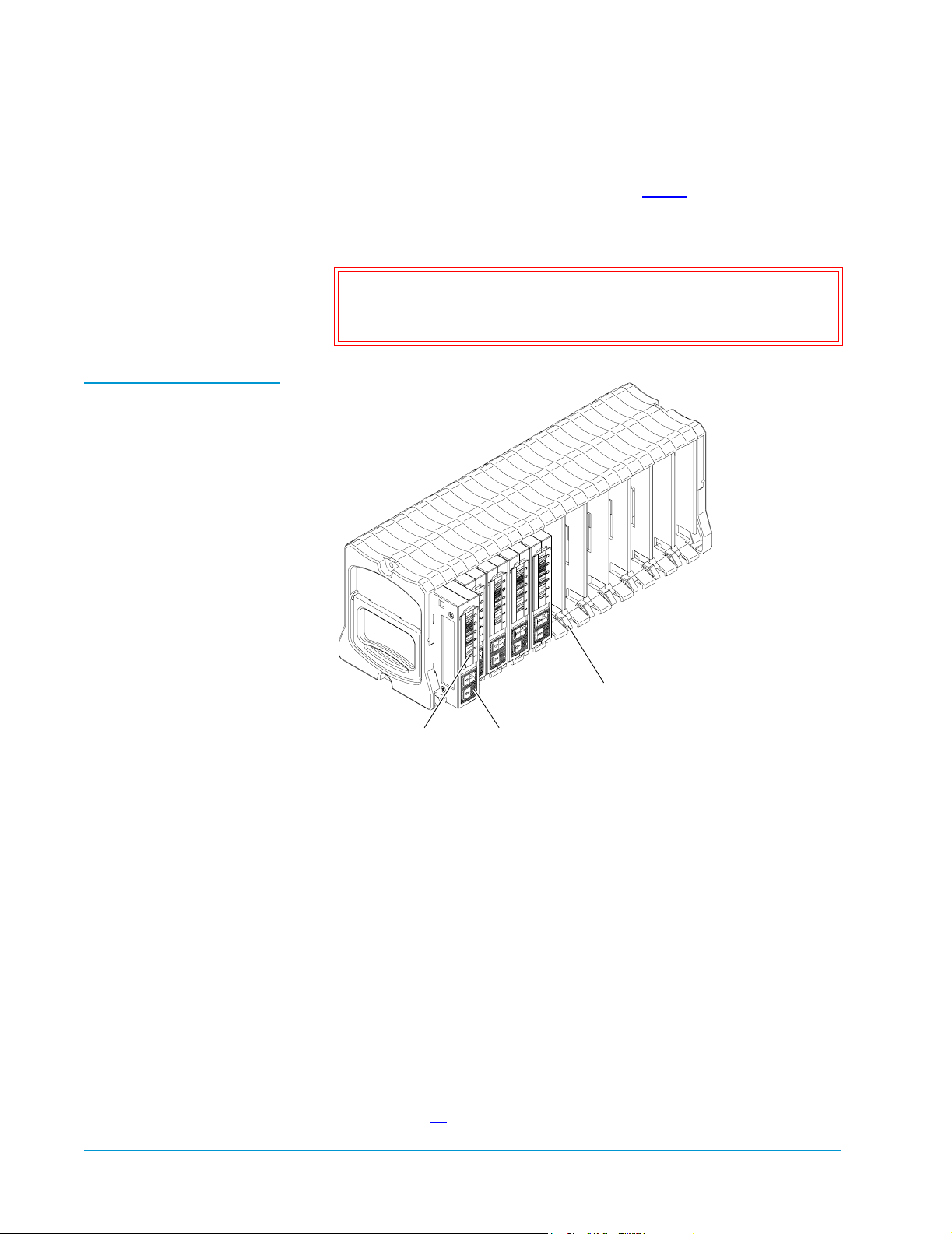
c Using a slender object such as a pen, press and hold the
magazine release button (see figure 18
d Pull the left magazine the rest of the way out of the library.
).
Magazine
release
button
2 Remove the right magazine:
a Press the white button next the right magazine access door and
open the door.
b Grasping the handle at the front of the right magazine, pull it
forward and out of the library.
3 Insert the cleaning cartridge into the fixed slot behind the left
magazine, orienting it with the label facing outward and the writeprotect switch:
• Down, if it is a DLT or SDLT cartridge
• Up, if it is an LTO cartridge
Preparing and Inserting Tape Cartridges 25
Page 26
Sun StorEdge™ L25 Tape Library and Sun StorEdge™ L100 Tape Library Installation Guide
Document 6423015-01, Ver. 1, Rel. 0
June 2002
4 Insert cartridges into each of the magazine slots:
a Orient the cartridges as described in step 3.
b Push each cartridge into a slot until the cartridge retaining latch
clicks to hold the cartridge in place.
Caution: The magazines are designed so that you cannot insert
cartridges incorrectly. Do not try to force the
cartridges into the slots.
Figure 19 Inserting DLT
Cartridges into a Magazine
Cartridge
retaining latch
Label Write-protect
switch
5 Insert the magazines into the library, sliding them back until they
click into place.
6 Close the magazine access doors.
Placing Tape Cartridges in an L100 Library 0
To place tape cartridges in an L100 library:
1 Press the white buttons next to the magazine access doors.
The magazine access doors open.
2 Remove the level 1 left magazine:
a Grasping the handle at the front of the level 1 left magazine,
pull it forward until it stops.
b If the magazine stops after the first slot, perform steps 2c
through 2
e to release it.
26 Preparing and Inserting Tape Cartridges
Page 27
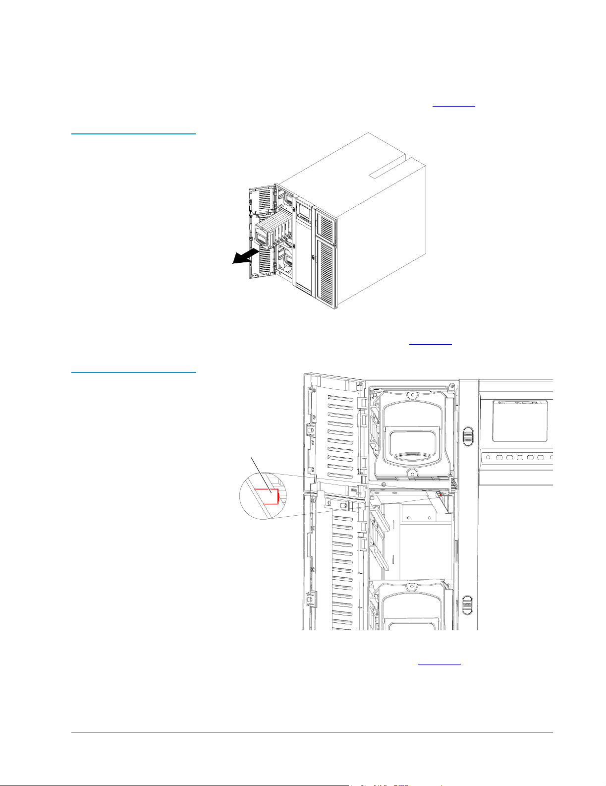
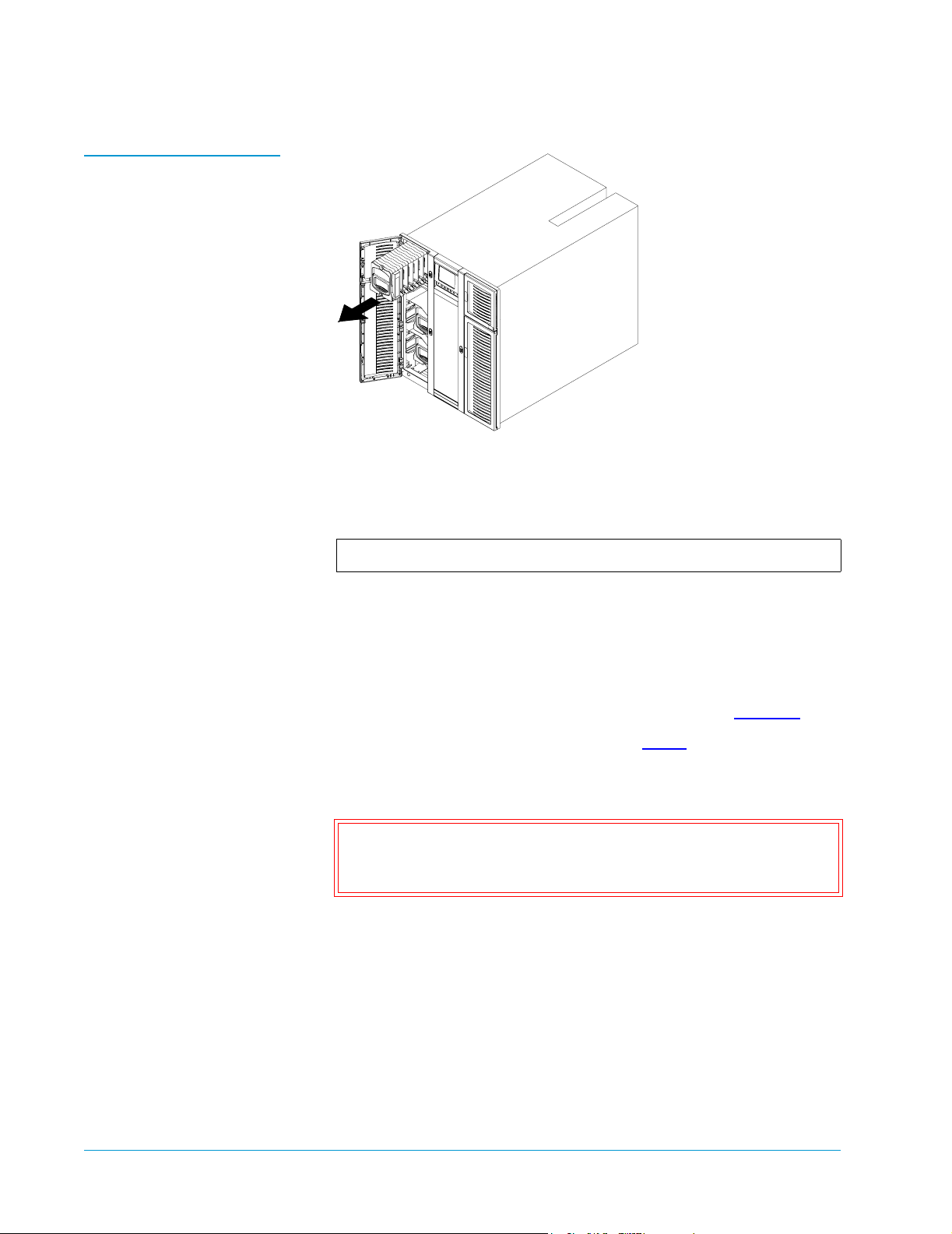
Figure 20 Removing the
Level 2 Left Magazine
Sun StorEdge™ L25 Tape Library and Sun StorEdge™ L100 Tape Library Installation Guide
Document 6423015-01, Ver. 1, Rel. 0
June 2002
c Remove the level 2 left magazine (see figure 20).
d Reach into the library underneath the level 1 left magazine and
press up on the release latch (see figure 21
).
Figure 21 Pressing the
Release Latch
Release latch
e While holding the release latch, pull the level 1 left magazine
forward and out of the library (see figure 22
).
Preparing and Inserting Tape Cartridges 27
Page 28
Sun StorEdge™ L25 Tape Library and Sun StorEdge™ L100 Tape Library Installation Guide
Document 6423015-01, Ver. 1, Rel. 0
June 2002
Figure 22 Removing the
Level 1 Left Magazine
3 Remove each remaining magazine by grasping the handle at the
front of the magazine and sliding it forward and out of the library.
4 Insert cleaning cartridges into the fixed slots.
Note: There is one fixed slot behind each left magazine.
Orient the cartridges with the label facing outward and the writeprotect switch:
• Down, if it is a DLT or SDLT cartridge
• Up, if it is an LTO cartridge
5 Insert cartridges into each of the magazine slots (see figure 19):
a Orient the cartridges as described in step 4.
b Push each cartridge into a slot until the cartridge retaining latch
clicks to hold the cartridge in place.
Caution: The magazines are designed so that you cannot insert
cartridges incorrectly. Do not force the cartridges into
the slots.
6 Insert the magazines into the library, sliding them back until they
click into place.
7 Close the magazine access doors.
28 Preparing and Inserting Tape Cartridges
Page 29
Sun StorEdge™ L25 Tape Library and Sun StorEdge™ L100 Tape Library Installation Guide
Document 6423015-01, Ver. 1, Rel. 0
June 2002
Connecting the Library to AC Power 0
This section explains how to connect the library to AC power.
L25 Power Requirements
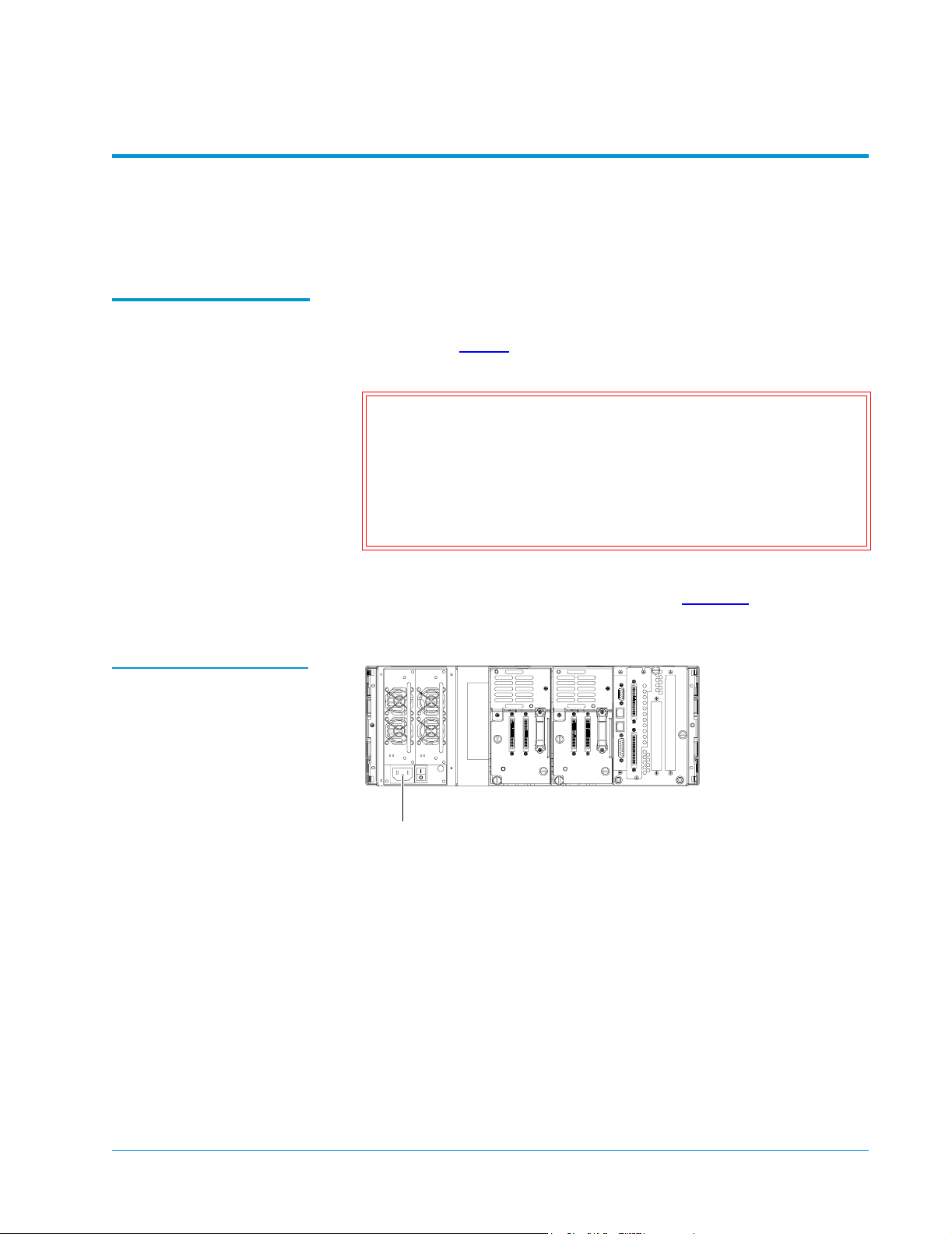
Figure 23 Power Inlet
To connect the L25 library to AC power:
0
1 Referring to table 4, select appropriate AC distribution unit(s) for
your library configuration and input voltage.
Warning: AC distribution units (power strips) must be certified
for safety by an agency acceptable to the country of
use. For use in the United States and Canada,
distribution units must be UL listed and CSA
certified. For use in Europe, distribution units must
be CE marked. National certifications for other
countries depend on local requirements.
2 Connect the power cable (provided in the accessories kit) to the
power inlet on the back of the library (see figure 23
) and to the AC
distribution unit.
Power inlet
Connecting the Library to AC Power 29
Page 30

Sun StorEdge™ L25 Tape Library and Sun StorEdge™ L100 Tape Library Installation Guide
Document 6423015-01, Ver. 1, Rel. 0
June 2002
Table 4 AC Distribution
Requirements, L25
Distribution Unit Requirements
# of
Library
Modules
200-240V 50-60Hz supply voltage (Europe
& international, etc.)
100-120V 50-60Hz supply voltage (USA,
Canada, Japan, etc.)
1-2 Connect libraries to one AC distribution unit
rated minimum 10A, minimum 1.00mm2
<HAR> cord with minimum 10A plug. Must
be 3 wire grounding plug and wall outlet.
3-4 Select one of the following options:
• Connect no more than 2 libraries to each
AC distribution unit rated minimum 10A,
minimum 1.00mm2 <HAR> cord with
minimum 10A plug. Must be 3 wire
grounding plug and wall outlet. The AC
distribution units must be plugged into
separate outlets served by separate circuit
breakers or fuses.
• Connect all libraries to one AC distribution
unit rated minimum 10A, minimum
1.00mm2 <HAR> 3 wire cord with 3 wire
IEC60309 rated 16A. Must be 3 wire
grounding plug and wall outlet and have a
ground warning label.
• Connect all libraries to one AC distribution
unit rated minimum 10A, minimum 1.00
mm2 <HAR> 3 wire cord permanently
wired to the electrical supply. Must be
connected with a 3 wire cable and have a
ground warning label.
Connect libraries to one UL Listed AC
distribution unit rated 15A or 20A, with a
minimum 14AWG 3 wire cord, and a 15A or
20A plug. Must be 3 wire grounding plug and
wall outlet.
Connect libraries to one UL Listed AC
distribution unit rated 15A or 20A, with a
minimum 14AWG 3 wire cord, and a 15A or
20A plug. Must be 3 wire grounding plug and
wall outlet.
30 Connecting the Library to AC Power
Page 31

# of
Library
Modules
Sun StorEdge™ L25 Tape Library and Sun StorEdge™ L100 Tape Library Installation Guide
Distribution Unit Requirements
200-240V 50-60Hz supply voltage (Europe
& international, etc.)
Document 6423015-01, Ver. 1, Rel. 0
June 2002
100-120V 50-60Hz supply voltage (USA,
Canada, Japan, etc.)
5-10 Select one of the following options:
• Connect no more than 2 libraries to each
AC distribution unit rated minimum 10A,
minimum 1.00mm2 <HAR> cord with
minimum 10A plug. Must be 3 wire
grounding plug and wall outlet. The AC
distribution units must be plugged into
separate outlets served by separate circuit
breakers or fuses.
• Connect all libraries to one AC distribution
unit rated minimum 10A, minimum
1.00mm2 <HAR> 3 wire cord with 3 wire
IEC60309 rated 16A. Must be 3 wire
grounding plug and wall outlet and have a
ground warning label.
• Connect all libraries to one AC distribution
unit rated minimum 10A, minimum 1.00
mm2 <HAR> 3 wire cord permanently
wired to the electrical supply. Must be
connected with a 3 wire cable and have a
ground warning label.
Select one of the following options:
• Connect no more than 4 libraries to each
AC distribution unit rated 15A or 20A, with
a minimum 14AWG 3 wire cord, and a 15A
or 20A plug. Must be 3 wire grounding
plug and wall outlet.
• Connect all libraries to one AC distribution
unit rated 20A, with a minimum 14AWG 3
wire cord, with a 20A plug. Must be 3 wire
grounding plug and wall outlet and have a
ground warning label.
• Connect all libraries to one AC distribution
unit rated minimum 20A, with a minimum
14AWG 3 wire cord, permanently wired to
the electrical supply and have a ground
warning label.
Connecting the Library to AC Power 31
Page 32
Sun StorEdge™ L25 Tape Library and Sun StorEdge™ L100 Tape Library Installation Guide
Document 6423015-01, Ver. 1, Rel. 0
June 2002
L100 Power Requirements
To connect the L100 library to AC power:
0
1 Referring to table 5, select appropriate AC distribution unit(s) for
your library configuration and input voltage.
Warning: AC distribution units (power strips) must be certified
for safety by an agency acceptable to the country of
use. For use in the United States and Canada,
distribution units must be UL listed and CSA
certified. For use in Europe, distribution units must
be CE marked. National certifications for other
countries depend on local requirements.
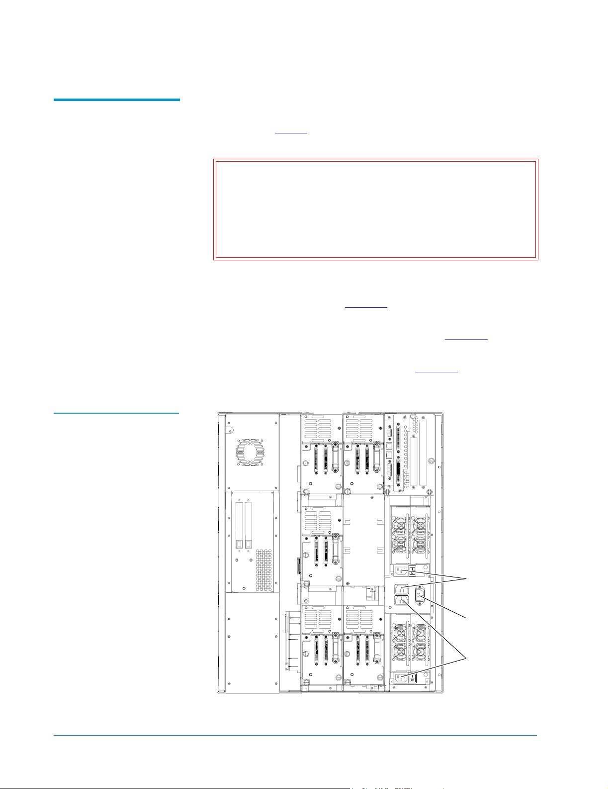
2 Using one of the short AC power cables provided in the accessory
kit, connect the top power supply to the AC distribution panel on
the back of the library (see figure 24
3 Using the remaining short AC power cable, connect the bottom
power supply to the AC distribution panel (see figure 24
4 Connect the power cable (provided in the accessories kit) to the
power inlet on the back of the library (see figure 24
).
).
) and to the wall
outlet or AC distribution unit.
Figure 24 Power Inlet
Connect these
using a short
power cable
Connect this inlet
to the wall outlet
or AC distribution
unit
Connect these
using a short
power cable
32 Connecting the Library to AC Power
Page 33

Table 5 AC Distribution
Requirements, L100
Distribution Unit Requirements
# of
Library
Modules
200-240V 50-60Hz supply voltage (Europe
& international, etc.)
Sun StorEdge™ L25 Tape Library and Sun StorEdge™ L100 Tape Library Installation Guide
Document 6423015-01, Ver. 1, Rel. 0
June 2002
100-120V 50-60Hz supply voltage (USA,
Canada, Japan, etc.)
1 Connect the library to an AC wall outlet rated
minimum 10A, minimum 1.00mm
2
<HAR>
cord with minimum 10A plug. Must be three
wire grounding plug and wall outlet.
2 Connect each library to a separate wall outlet
rated minimum 10A, minimum 1.00mm
2
<HAR> cord with minimum 10A plug. Must
be three wire grounding plug and wall outlet.
3 Select one of the following options:
• Connect each library to a separate wall
outlet rated minimum 10A, minimum
1.00mm2 <HAR> cord with minimum 10A
plug. Must be three wire grounding plug
and wall outlet.
• Connect all libraries to one AC distribution
unit rated minimum 10A, minimum
1.00mm
2
<HAR> 3 wire cord with 3 wire
IEC60309 rated 16A. Must be 3 wire
grounding plug and wall outlet and have a
ground warning label.
Connect the library to one UL listed AC
distribution unit rated 15A or 20A, with a
minimum 14AWG 3 wire cord, and a 15A or
20A plug. Must be three wire grounding plug
and wall outlet.
Connect both libraries to one UL listed AC
distribution unit rated 15A or 20A, with a
minimum 14AWG 3 wire cord, and a 15A or
20A plug. Must be three wire grounding plug
and wall outlet.
Select one of the following options:
• Connect no more than 2 libraries to each of
two AC distribution units rated 15A or 20A,
with a minimum 14AWG 3 wire cord, and a
15A or 20A plug. Must be 3 wire grounding
plug and wall outlet. The AC distribution
units must be plugged into separate outlets
served by separate circuit breakers or fuses.
• Connect all libraries to one AC distribution
unit rated 20A, with a minimum 14AWG 3
wire cord, with a 20A plug. Must be 3 wire
grounding plug and wall outlet.
• Connect all libraries to one distribution unit
rated minimum 10A, minimum 1.00mm
2,
<HAR> 3 wire cord permanently wired to
the electrical supply. Must be connected
with a 3 wire cable and have a ground
warning label.
Connecting the Library to AC Power 33
• Connect all libraries to one AC distribution
unit rated minimum 20A, with a minimum
14AWG 3 wire cord, permanently wired to
the electrical supply.
Page 34

Sun StorEdge™ L25 Tape Library and Sun StorEdge™ L100 Tape Library Installation Guide
Document 6423015-01, Ver. 1, Rel. 0
June 2002
Connecting the Library to the Host Computer 0
The library robotics and tape drives are independent SCSI devices with
independent SCSI connections. The L25 and L100 provide two 68-pin
high density connectors for each device. You can connect these devices
to a single SCSI bus or divide them between two or more SCSI buses.
To connect the library or libraries to the host computer(s), refer to the
following sections:
• SCSI Cabling Guidelines
• Terminato r Pow er
• SCSI Cabling Diagrams
SCSI Cabling Guidelines
Terminator Power 0
Refer to these SCSI cabling guidelines when completing the SCSI
0
cabling:
• Each device on the SCSI bus must have a unique SCSI ID. The
default settings for the L25 are: library robotics = 0, tape drive 1 = 1,
tape drive 2 =2. The default settings for the L100 are: library
robotics = 0, tape drive 1 = 1, tape drive 2 = 2, tape drive 3 = 3, tape
drive 4 = 4, tape drive 5 = 15, tape drive 6 = 14. You can change
these SCSI ID settings using the
the GUI
Configuration screen.
Drive ID and Library ID options on
• Termination must be provided at each end of the SCSI bus (see
Terminato r Pow er
).
• All SCSI cables must be shielded or double shielded to meet EMI
specifications.
• The maximum total SCSI bus length for an HVD SCSI bus is 82 feet
(25 meters).
External terminators must be installed at the end of each SCSI bus.
Power for the terminator must be supplied by at least one device on
the SCSI bus.
In the factory default configuration, the library robotics supplies
terminator power. You can turn this terminator power off using the
Terminator Power option on the GUI Configuration screen.
34 Connecting the Library to the Host Computer
Page 35
Sun StorEdge™ L25 Tape Library and Sun StorEdge™ L100 Tape Library Installation Guide
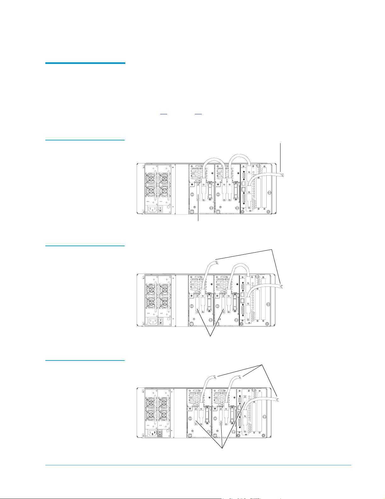
To host
To host
To host
Document 6423015-01, Ver. 1, Rel. 0
June 2002
SCSI Cabling Diagrams
Figure 25 SCSI Cabling
Diagram, L25 — Single
SCSI Bus
Figure 26 SCSI Cabling
Diagram, L25 — Two SCSI
Buses
This section provides sample SCSI cabling configurations for L25 and
0
L100 libraries.
SCSI Cabling Diagrams, L25 0
Figures 25
through 27 illustrate sample SCSI cabling configurations for
a single L25 library module.
computer
Terminator
computer
Figure 27 SCSI Cabling
Diagram, L25 — Three
SCSI Buses
Terminator
computer
Terminator
Connecting the Library to the Host Computer 35
Page 36
Sun StorEdge™ L25 Tape Library and Sun StorEdge™ L100 Tape Library Installation Guide
Document 6423015-01, Ver. 1, Rel. 0
June 2002
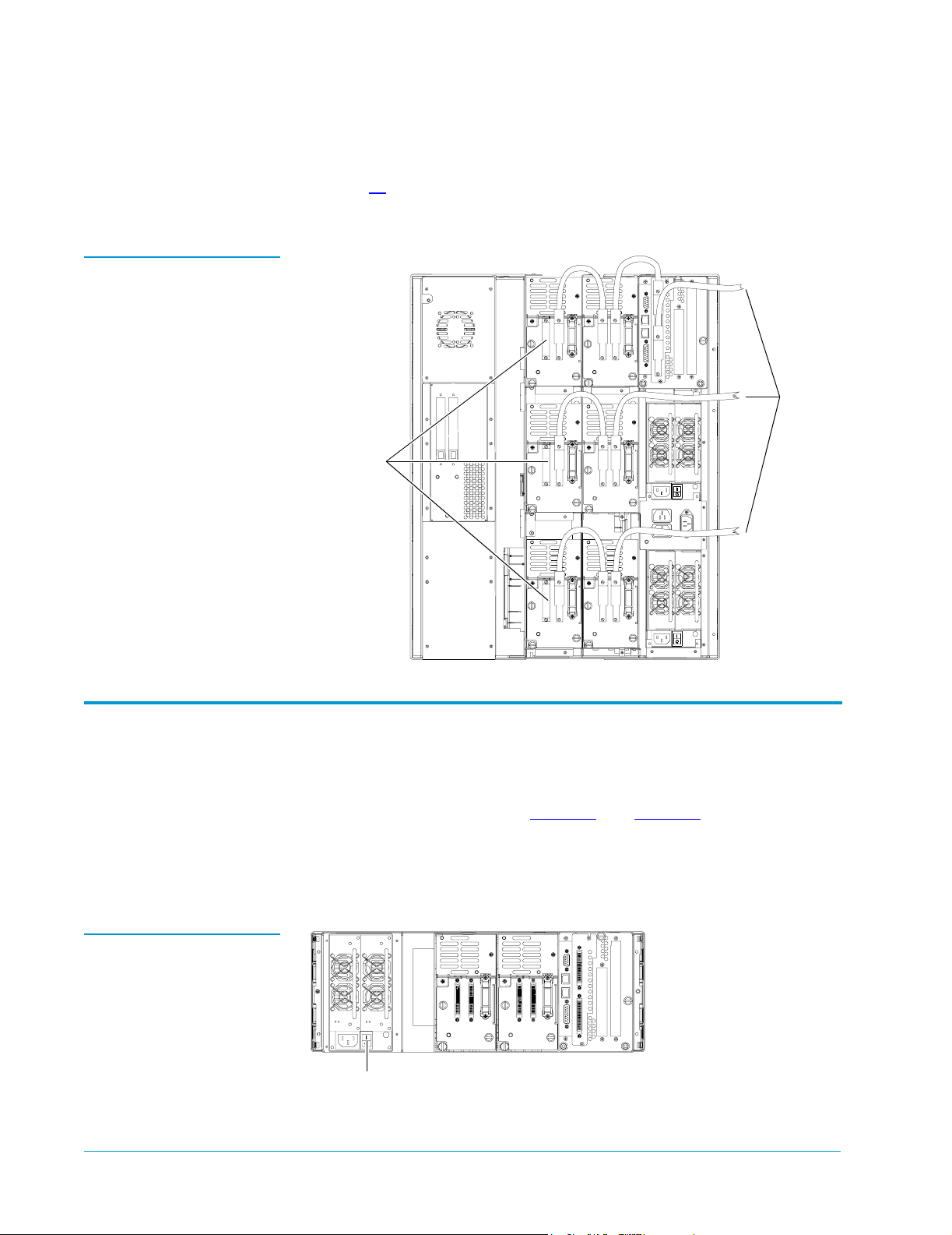
SCSI Cabling Diagram, L100 0
Figure 28 SCSI Cabling
Diagram, L100
Figures 28
illustrates the recommended SCSI cabling configuration for
a single L100 library module.
Terminators
To host
computer
Powering Up the Library 0
To power up the library, press the power switch (or switches) on the
back panel of the library (see figure 29
To minimize the effects of inrush current, always turn on the library
using these library power switches instead of using the power
switches that may be on the AC distribution unit.
Figure 29 Power Switch,
L25
Power switch
36 Powering Up the Library
and figure 30).
Page 37
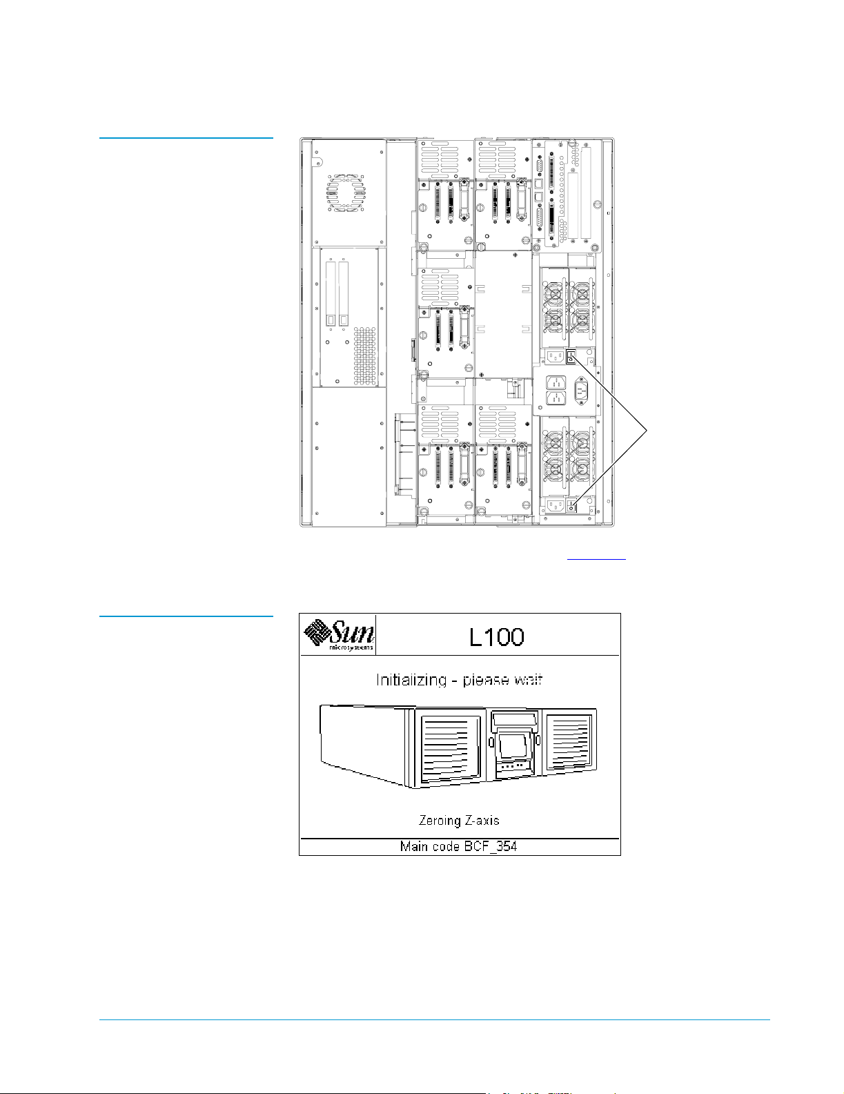
Figure 30 Power
Switches, L100
Sun StorEdge™ L25 Tape Library and Sun StorEdge™ L100 Tape Library Installation Guide
Document 6423015-01, Ver. 1, Rel. 0
June 2002
Power switches
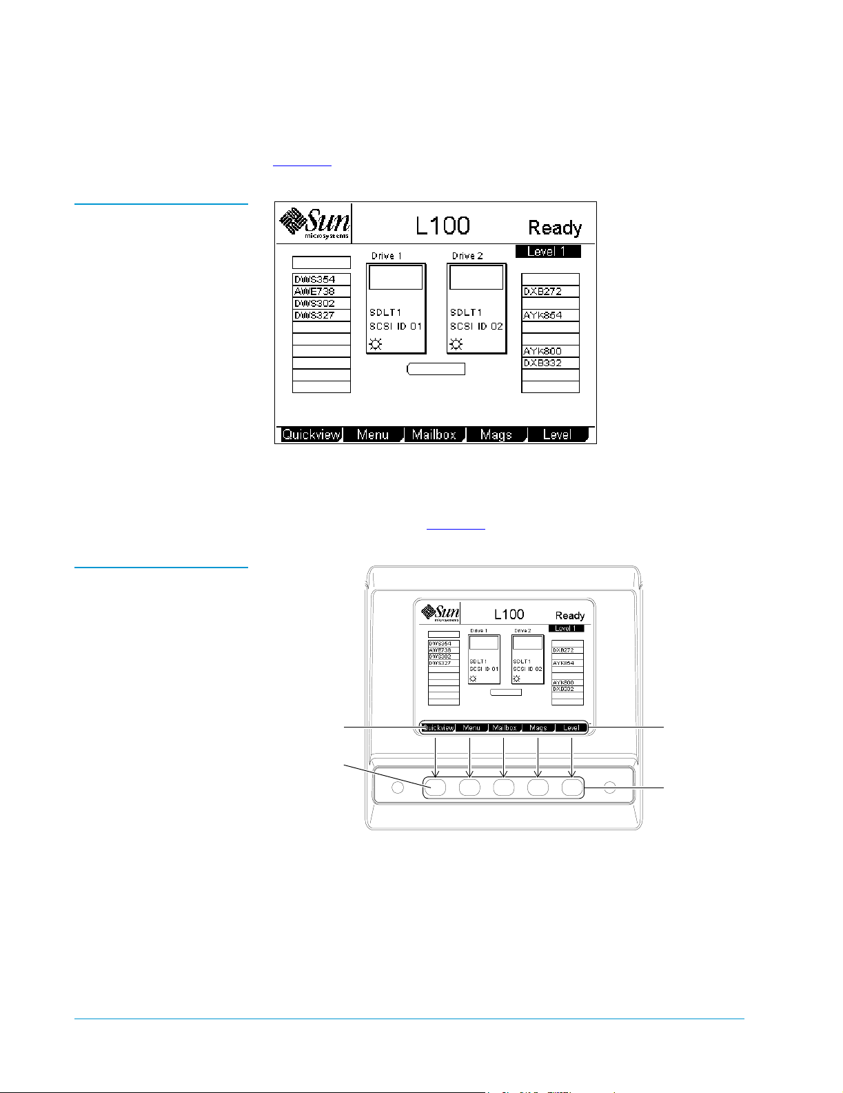
Figure 31 Welcome
Screen, L100
The GUI displays a welcome screen (see figure 31) and the library runs
a power-on self-test (POST).
Powering Up the Library 37
Page 38
Sun StorEdge™ L25 Tape Library and Sun StorEdge™ L100 Tape Library Installation Guide
Document 6423015-01, Ver. 1, Rel. 0
June 2002
When the POST is complete, the GUI displays the main screen (see
figure 32
Figure 32 Main Screen,
L100
).
Figure 33 Using the GUI
Buttons
At the bottom of each GUI screen are up to five button labels. These
labels indicate the functions of the five push buttons below the GUI. To
select a function, press the push button directly below the button label
on the GUI screen (see figure 33
To select this
function,
press this
button:
).
Button
labels
Push
buttons
38 Powering Up the Library
Page 39
Sun StorEdge™ L25 Tape Library and Sun StorEdge™ L100 Tape Library Installation Guide
Document 6423015-01, Ver. 1, Rel. 0
June 2002
Disabling Unused Drive Bays 0
To complete the library installation, disable any unused drive bays as
follows:
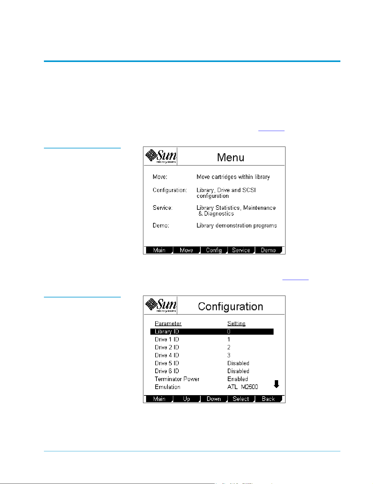
1 On the main screen, press Menu.
Figure 34 Menu Screen
Figure 35
Configuration Screen
The GUI displays the
2 Press Config.
The GUI displays the
Menu screen (see figure 34).
Configuration screen (see figure 35).
3 Press the Up or Down buttons until the drive ID for the unused
drive bay is highlighted.
4 Press Select.
Disabling Unused Drive Bays 39
Page 40
Sun StorEdge™ L25 Tape Library and Sun StorEdge™ L100 Tape Library Installation Guide
Document 6423015-01, Ver. 1, Rel. 0
June 2002
5 Press the Down button until the Disabled setting is selected.
Caution: Set the drive SCSI ID to Disabled only if there is no
drive installed in the drive bay.
6 Press Select.
7 Repeat steps 3 through 6 to disable any other unused drive bays.
8 Press Main to return to the main screen.
Caution: If you do not return to the main screen after changing
this setting, your change will not be saved to
NVRAM.
Note: You must reboot the library before this setting will take
effect.
9 Turn the library off and then back on again.
The library is now ready for operation.
Note: It is recommended that you check the library
configuration settings and change them as necessary
before configuring your backup software, especially the
Import/Export option setting.
Made in the USA.
Quantum Corporation provides this publication “as is” without warranty of any kind, either express or implied, including but not limited
to the implied warranties of merchantability or fitness for a particular purpose. Quantum Corporation may revise this publication from
time to time without notice.
COPYRIGHT STATEMENT
© Copyright 2002 by Quantum Corporation. All rights reserved.
Your right to copy this document is limited by copyright law. Making copies or adaptations without prior written authorization of
Quantum Corporation is prohibited by law and constitutes a punishable violation of the law.
TRADEMARK STATEMENT
StackLink is a trademark of Quantum Corporation.
Sun StorEdge™ L25 Tape Library and Sun StorEdge™ L100 Tape Library are trademarks of Sun Microsystems, Inc.
Other trademarks may be mentioned herein which belong to other companies.
 Loading...