

Page 1

Sun StorEdge network FC switch-8
and switch-16
Field Troubleshooting Guide
Sun Microsystems, Inc.
901 San Antonio Road
Palo Alto, CA 94303
U.S.A. 650-960-1300
Part No.816-0252-10
April 2001, Revision A
Send comments about this document to: [email protected]
Page 2

Copyright 2001Sun Microsystems, Inc.,901 SanAntonio Road• PaloAlto, CA94303-4900 USA.All rightsreserved.
This product ordocument isprotected bycopyright anddistributed underlicenses restrictingits use, copying, distribution, and decompilation.
No part of this productor documentmay bereproduced in any form by any means without prior written authorization of Sun and its licensors,
if any.Third-party software, includingfont technology,is copyrightedand licensedfrom Sunsuppliers.
Parts of the product maybe derivedfrom BerkeleyBSD systems,licensed fromthe University of California. UNIX is a registered trademarkin
the U.S. and other countries, exclusively licensed through X/OpenCompany,Ltd. For Netscape Communicator™, the following notice applies:
Copyright 1995 Netscape Communications Corporation. All rights reserved.
Sun, Sun Microsystems,the Sunlogo, AnswerBook2,docs.sun.com, SunStorEdge networkFC switch-8,and Solarisare trademarks,registered
trademarks, or service marks of Sun Microsystems,Inc. inthe U.S.and othercountries. AllSPARCtrademarks areused under license and are
trademarks or registeredtrademarks ofSPARCInternational, Inc. in the U.S. and other countries. Productsbearing SPARCtrademarks are
based upon an architecture developedby SunMicrosystems, Inc.
The OPEN LOOK and Sun™ Graphical User Interface was developed bySun Microsystems,Inc. forits usersand licensees.Sun acknowledges
the pioneering effortsof Xeroxin researchingand developing the concept of visual orgraphical userinterfaces forthe computerindustry.Sun
holds a non-exclusive license fromXerox tothe XeroxGraphical User Interface, which license also covers Sun’s licensees who implement OPEN
LOOK GUIs and otherwise comply with Sun’s written license agreements.
RESTRICTEDRIGHTS: Use, duplication, or disclosure bythe U.S. Government is subject to restrictions of FAR 52.227-14(g)(2)(6/87) and
FAR52.227-19(6/87), or DFAR252.227-7015(b)(6/95) and DFAR227.7202-3(a).
DOCUMENTATIONIS PROVIDED “ASIS” AND ALL EXPRESS OR IMPLIED CONDITIONS, REPRESENTATIONS AND WARRANTIES,
INCLUDING ANY IMPLIED WARRANTY OF MERCHANTABILITY, FITNESS FOR A PARTICULAR PURPOSE OR NONINFRINGEMENT, ARE DISCLAIMED, EXCEPT TO THE EXTENT THAT SUCH DISCLAIMERS ARE HELD TO BE LEGALLY INVALID.
Copyright 2001 Sun Microsystems, Inc.,901 SanAntonio Road• PaloAlto, CA94303-4900 Etats-Unis.Tousdroits réservés.
Ce produit oudocument estprotégé parun copyrightet distribuéavec deslicences quien restreignentl’utilisation,la copie,la distribution,et la
décompilation. Aucune partie de ce produit oudocument nepeut êtrereproduitesous aucuneforme, parquelque moyenque cesoit, sans
l’autorisation préalable et écrite de Sun et de ses bailleurs delicence, s’ily ena. Lelogiciel détenupar destiers, etqui comprendla technologie
relativeaux policesde caractères,est protégépar un copyright et licencié par des fournisseurs de Sun.
Des parties de ce produitpourront êtredérivées des systèmes Berkeley BSD licenciés par l’Université de Californie. UNIX est une marque
déposée aux Etats-Unis et dans d’autres payset licenciéeexclusivement parX/Open Company,Ltd. Lanotice suivanteest applicableà
Netscape Communicator™: Copyright 1995 Netscape Communications Corporation. Tousdroits réservés.
Sun, Sun Microsystems,the Sunlogo, AnswerBook2,docs.sun.com, SunStorEdge networkFC switch-8,et Solarissont desmarques defabrique
ou des marquesdéposées, oumarques deservice, deSun Microsystems,Inc. aux Etats-Unis et dans d’autres pays.Toutesles marquesSPARC
sont utilisées sous licence et sont des marques defabrique oudes marquesdéposées deSPARCInternational, Inc. aux Etats-Unis et dans
d’autrespays. Lesproduits portantles marquesSPARCsontbasés surune architecturedéveloppée parSun Microsystems,Inc.
L’interfaced’utilisation graphique OPEN LOOK et Sun™ a été développéepar SunMicrosystems, Inc.pour sesutilisateurs etlicenciés. Sun
reconnaîtles effortsde pionniersde Xeroxpour la rechercheet ledéveloppement duconcept desinterfaces d’utilisationvisuelle ougraphique
pour l’industrie de l’informatique. Sun détient une licence non exclusive deXerox surl’interface d’utilisationgraphique Xerox,cette licence
couvrant également les licenciés de Sun qui mettent en place l’interfaced’utilisation graphiqueOPEN LOOKet quien outrese conformentaux
licences écrites de Sun.
CETTE PUBLICATION EST FOURNIE "EN L’ETAT"ET AUCUNE GARANTIE, EXPRESSE OU IMPLICITE, N’EST ACCORDEE, YCOMPRIS
DES GARANTIESCONCERNANT LA VALEURMARCHANDE, L’APTITUDE DELA PUBLICATIONA REPONDRE A UNE UTILISATION
PARTICULIERE, OU LE FAIT QU’ELLE NE SOIT PAS CONTREFAISANTE DE PRODUIT DE TIERS. CE DENI DE GARANTIE NE
S’APPLIQUERAIT PAS, DANS LA MESURE OU IL SERAIT TENU JURIDIQUEMENT NUL ET NON AVENU.
Please
Recycle
Page 3

Preface
The Sun StorEdge network FC switch-8 and switch-16 Field Troubleshooting Guide
describes how to diagnose and troubleshoot the Sun StorEdge network FC switch-8
and switch-16 hardware. It provides information and pointers to additional
documentation you may need for installing, configuring, and using the
configuration. The book is primarily intended for use by experienced system
support engineers who already have a good understanding of the product.
Using UNIX Commands
This document may not contain information on basic UNIX®commands and
procedures such as shutting down the system, booting the system, and configuring
devices.
See one or more of the following for this information:
■ Solaris Handbook for Sun Peripherals
■ AnswerBook2™ online documentation for the Solaris™ operating environment
■ Other software documentation that you received with your system
iii
Page 4

Typographic Conventions
Typeface Meaning Examples
AaBbCc123 The names of commands, files,
and directories; on-screen
computer output
AaBbCc123
AaBbCc123 Book titles, new words or terms,
What you type, when
contrasted with on-screen
computer output
words to be emphasized
Edit your .login file.
Use ls -a to list all files.
% You have mail.
%
su
Password:
Read Chapter 6 in the User’s Guide.
These are called class options.
You must be superuser to do this.
Command-line variable; replace
with a real name or value
To delete a file, type rm filename.
Shell Prompts
Shell Prompt
C shell machine_name%
C shell superuser machine_name#
Bourne shell and Korn shell $
Bourne shell and Korn shell superuser #
iv Sun StorEdge Network FC Switch-8 and Switch-16 Field Troubleshooting Guide—April 2001
Page 5

Related Documentation
Application Title Part Number
Installer’s information
Sun StorEdge network FC switch-8
and switch-16 Installation, and
Configuration Guide
Installer/User’s
information
GUI and User
SANbox-8/16 Segmented Loop Switch
Management and User’s Manual
Sun SANbox 16 Segmented Loop
Switch User ’s Manual
Late news Sun StorEdge network FC switch-8 and
switch-16 Release Notes
Software CD 724-7491-01
T3 Installation,
Operations, and Service
T3 Administration Sun StorEdge T3 Disk Tray
A5x00 installation and
service
A5x00 configuration
information
RAID software
Sun StorEdge T3 Disk Tray Installations,
Operations and Service Manual
Administrator’s Guide
Sun StorEdge A5000 Installation and
Service Guide
Sun StorEdge A5000 Configuration Guide 802-0264-15
RAID Manager 6.22 User's Guide 806-0478-10
806-6922-10
875-3060-10 Rev.X
875-3059-10 Rev.X
806-6924-10
806-1062-11
806-1063-11
802-7573-16
Accessing Sun Documentation Online
The docs.sun.comsmweb site enables you to access select Sun technical
documentation on the Web. You can browse the docs.sun.com archive or search
for a specific book title or subject at:
http://docs.sun.com
Preface v
Page 6
Ordering Sun Documentation
Fatbrain.com, an Internet professional bookstore, stocks select product
documentation from Sun Microsystems, Inc.
For a list of documents and how to order them, visit the Sun Documentation Center
on Fatbrain.com at:
http://www.fatbrain.com/documentation/sun
Sun Welcomes Your Comments
Sun is interested in improving its documentation and welcomes your comments and
suggestions. You can email your comments to Sun at:
Please include the part number (for example, 806-6923-10) of your document in the
subject line of your email.
vi Sun StorEdge Network FC Switch-8 and Switch-16 Field Troubleshooting Guide—April 2001
Page 7

Contents
1. The Sun StorEdge Network FC Switch-8 and Switch-16 TroubleshootingGuide 1
Introduction 1
Supported Configurations 2
Sun StorEdge network FC switch-8 and FC switch-16 Configuration 2
Zoning 3
Supported Hardware Configurations 4
Required Solaris Level 5
Guidelines for Configuration 5
Multi-Host 13
Diagnostic Tools 16
Hardware Tools 16
Helpful Failure Information 17
FC Switch LEDs and Back Panel Controls 18
AC Input Power Connector and Fuses 22
Diagnosing and Troubleshooting the Switch 23
Power Checks and Troubleshooting 23
Power-On-Self-Test (POST) 23
Using the Test Mode Switch 25
Contents vii
Page 8

Heartbeat LED Blink Patterns 27
Cable Continuity Tests 32
Switch Counter Information 33
Counter Descriptions 35
Diagnostic Information and Isolation 41
Sun StorEdge StorTools 4.x qlctest 41
Sun StorEdge StorTools 4.x switchtest 42
Examples of Fault Isolation 46
Scenario 1a—Bad Cable Between Host and Switch (Using StorEdge Expert)
46
Scenario 2—Bad GBIC in Switch 48
Scenario 1b—Bad Cable Between Host and Switch (Using Functional Test) 51
A Quick Functional Test (a5ksestest) to Test Full Loop 54
Scenario 3—Catastrophic Switch Failure 56
Scenario 4—Bad Cable from Switch to Storage 59
Scenario 5—Bad GBIC in Storage (A5200) 67
A. Mamba Field Troubleshooting Guide FAQ 73
B. Isolation of SAN Components Flowchart 89
C. Brocade Troubleshooting 99
Introduction 100
Troubleshooting Overview 117
Glossary 131
Index 135
Contents viii
Page 9

List of Figures
FIGURE 1 Switch and Interconnections 1
FIGURE 2 Example: Single Host Connected to One Sun StorEdge A3500FC Controller Module Using
Switches 7
FIGURE 3 Example: Single Host Connected to One Sun StorEdge A5200 Controller Module Using
Switches 7
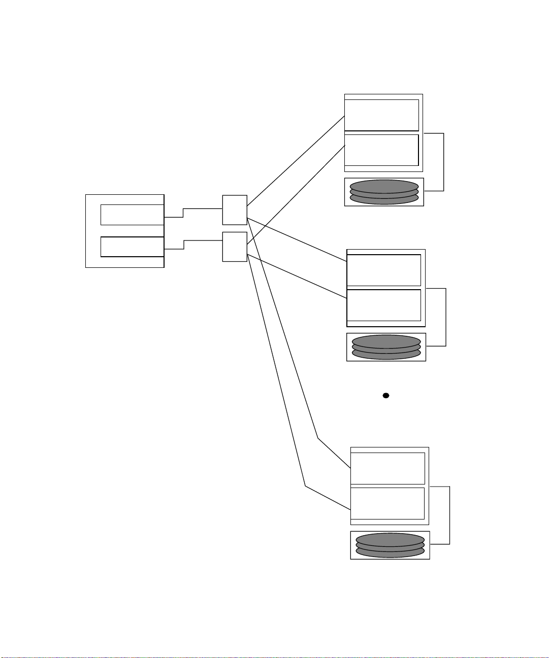
FIGURE 4 Example: Single Host Connected to One Sun StorEdge T3 Partner Pair Using Switches 8
FIGURE 5 Example: Single Host to Multiple A3500-FC Controller Modules Using switches 9
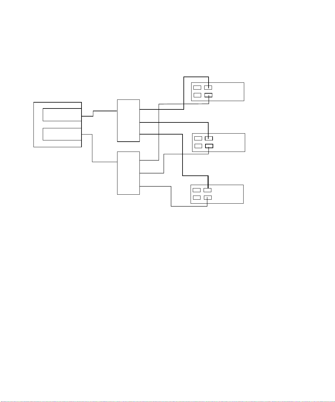
FIGURE 6 Example: Single Host to Multiple A5200 Controller Modules Using switches 10
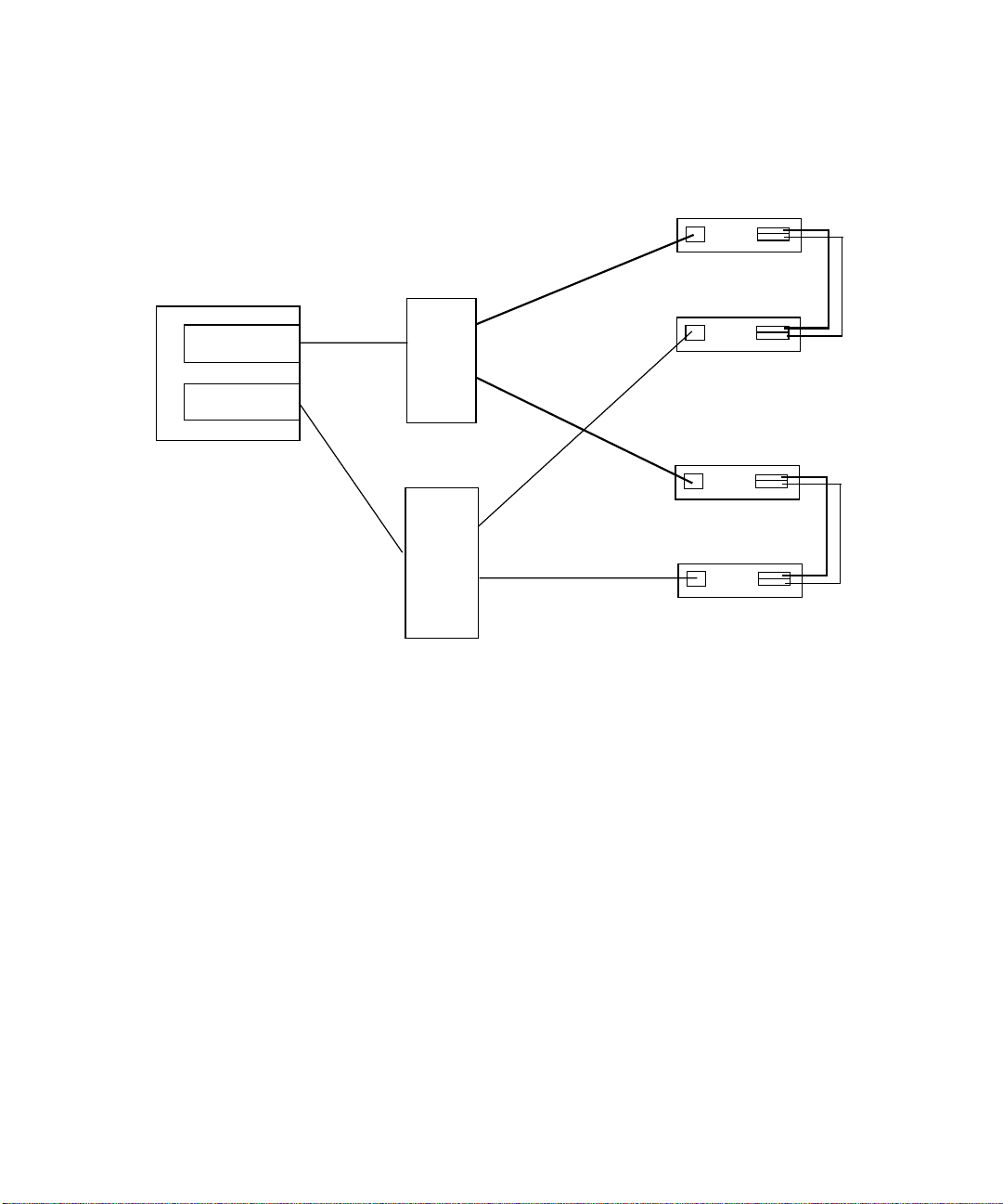
FIGURE 7 Example: Single Host to Two StorEdge T3 Partner Pairs using switches 11
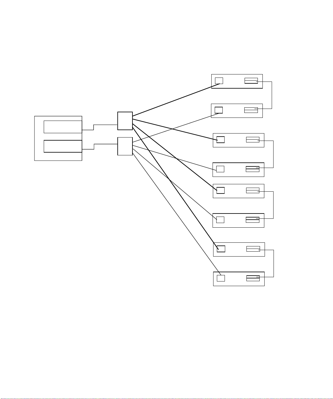
FIGURE 8 Example: Single Host Connected to Multiple StorEdge T3 Partner Pairs, Using Switches 12
FIGURE 9 Two Hosts Connected to up to Four Sun StorEdge A3500-FC Controller Modules using
switches 13
FIGURE 10 Example: Two Hosts Connected to Three Sun StorEdge A5200 Controller Modules using
Switches 14
FIGURE 11 Example: Two Hosts Connected to Four Sun StorEdge T3 Partner Pairs Using Switches 15
FIGURE 12 Chassis Back (8-Port Switch) 18
FIGURE 13 Chassis Back (16-Port Switch) 19
FIGURE 14 Test Mode Switch Functions and Positions 26
FIGURE 15 Heartbeat LED—Normal 27
FIGURE 16 Heartbeat LED—Failure Blink Patterns 28
FIGURE 17 Port Display 34
List of Figures ix
Page 10

FIGURE 18 Web GUI 38
FIGURE 19 Sun StorEdge StorTools 4.x qlctest 41
FIGURE 20 Sun StorEdge StorTools 4.x Switch Test or SANSurfer GUI Start Test 42
FIGURE 21 Sun StorEdge StorTools 4.x Array Tests 43
FIGURE 22 Isolation in Areas 1, 2, and 3 44
FIGURE 23 Functional Test of Switch window 57
FIGURE 24 Switch GUI window 58
FIGURE 25 Functional Test (switchtest) on Initiator Port to Test Host-Switch Link window 60
FIGURE 26 Functional Test (switchtest) on Destination Port to Test Switch-Storage Link window 62
FIGURE 27 Insert Loopback in Destination Port to Test Switch’s GBIC window 64
FIGURE 28 Rerun a5ksesTest window 66
FIGURE 29 Run Snapshot DIFF window 68
FIGURE 30 Systematic Isolation of the Various SAN Components 90
List of Figures x
Page 11

List of Tables
TABLE 1 Supported Hardware 4
TABLE 2 Arrays, Zones, and Initiators 6
TABLE 3 Dynamic Addition to a Zone* (without reboot of host) 6
TABLE 4 Port Display Window Counters 35
TABLE 5 Counter Names and Descriptions (Faceplate Window) 39
List of Tables xi
Page 12

xii Sun StorEdge Network FC Switch-8 and Switch-16 Field Troubleshooting Guide—April 2001
Page 13
The Sun StorEdge Network FC Switch-8 and Switch-16 Troubleshooting Guide
Introduction
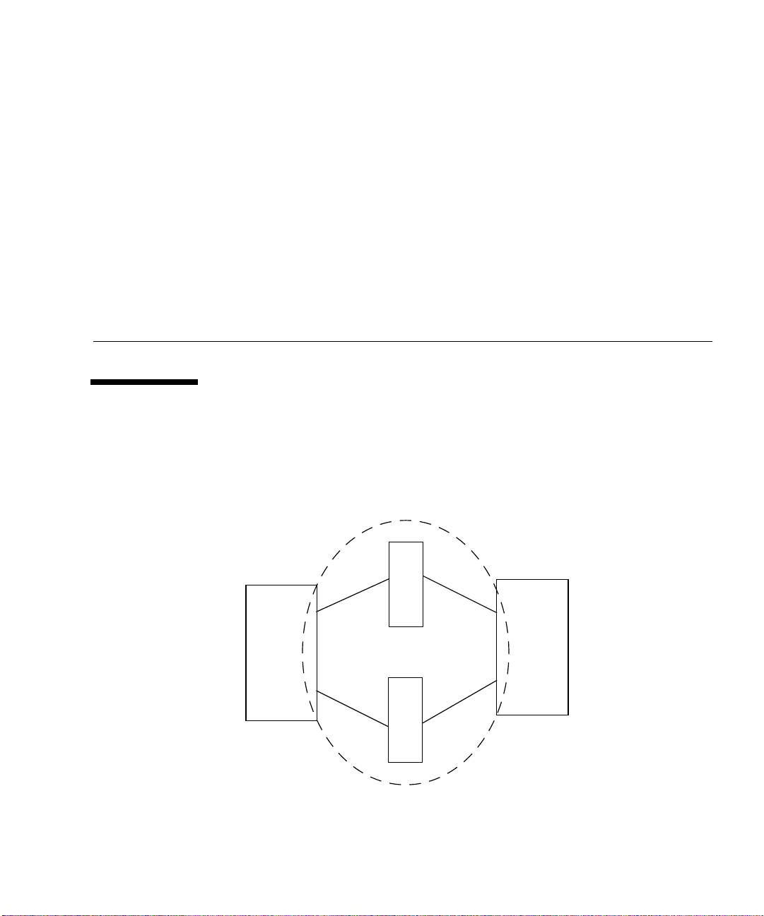
The scope of this document includes the switch and the interconnections (HBA,
GBIC, cables) on either side of the switch, as shown in the following diagram.
Switch
Host
Switch
FIGURE 1 Switch and Interconnections
Storage
1
Page 14

This troubleshooting guide is intended to provide basic guidelines that can be used
for isolating problems for the supported configurations identified in this document.
It also assumes you have been trained on all the components that comprise storage
and switch configurations.
Sun StorEdge StorTools 4.01 or above is required to support the configurations in
this document. Throughout this document, the newest version will be referred to as
Sun StorEdge StorTools 4.x.
Additional information and resources are available at
http://www.sun.com/service/support/sunsolve/index.html
The website contains information on software versions, and provides necessary
patches for customers.
Supported Configurations
Note –
Be sure that all systems are running Solaris 8 (10/00 release and later) and that the
necessary patches for switch support are installed.
Sun StorEdge network FC switch-8 and FC switch-16 Configuration
The Sun StorEdge network FC switch-8 and switch-16 can be configured into
multiple zones. Each zone forms an arbitrated loop, and each zone is isolated from
other zones on the same switch. Sun supports one or two hosts and up to four
devices per zone (see
Each zone must have at least two ports and may have up to the number of ports on
the switch. For example, the 8-port switch may have four zones; the 16-port switch
may have eight zones. Typical zone configurations are sized for the number of hosts
and devices to be connected. The number of devices supported per zone depends on
the device type. Unconfigured ports default to the orphan zone and may be added to
an active zone later, as needed. For more information see the Sanbox 8/16 Segmented
Loop Switch Management User’s Manual, which is packaged with the switch.
Different adapter ports on a host can be connected to different loops. This allows a
host to participate on multiple loops.
2 Sun StorEdge Network FC Switch-8 and Switch-16 Field Troubleshooting Guide • April, 2001
FIGURE 2 through FIGURE 11).
Page 15

For more information on loop configurations and zoning, refer to the Sun StorEdge
network FC switch-8 and switch-16 Installation and Configuration Guide and the SANbox
8/16 Segmented Loop Switch Management User’s Manual , which are shipped with your
system.
Note – No more than one adapter port from any given host should be connected to
the same zone. This provides redundancy. For more information on supported
configurations, refer to the Sun StorEdge network FC switch-8 and switch-16 Installation
and Configuration Guide, which is shipped with your switch.
Zoning
For the 8-port switch you can configure a maximum of four zones, with a minimum
of two ports per zone. For the 16-port switch you can configure a maximum of eight
zones, with a minimum of two ports per zone.
In both the 8-port and 16-port switches, you can configure a maximum of four Sun
StorEdge A3500FC arrays per zone, or three Sun StorEdge A5200 arrays per zone, or
four Sun StorEdge T3 Disk Trays per zone.
For more information on zoning, refer to the Sun StorEdge network FC switch-8 and
switch-16 Installation and Configuration Guide and the SANbox 8/16 Segmented Loop
Switch Management User’s Manual, shipped with your system.
Sun StorEdge Network FC Switch-8 and Switch-16 Field Troubleshooting Guide—April, 2001 3
Page 16

Supported Hardware Configurations
Each switch is connected to the host through a fiber optic cable to a Sun StorEdge
PCI Single Fibre Channel Network Adapter. The other end of the switch is connected
to storage devices through a fiber optic cable.
TABLE 1 lists supported hardware, including part numbers and a brief description
of each item.
Note – The maximum length supported is 500m with shortwave GBICs and multi-
mode cable.
TABLE1 Supported Hardware
Part Number Description
540-4026 Sun StorEdge A3500-FC FC-AL controller for A3500 array (with
D1000 tray)
540-4027 Sun StorEdge A3500-FC FC-AL controller for A3000 array (with
RSM tray)
501-4158 Sun StorEdge A5200 array
950-3475 Sun StorEdge T3 array
X6799A StorEdge PCI Single Fibre Channel Network Adapter
X6731A GBIC Gigabit Interface Converter for the SBus FC-100 Host
Adapter
X973A 2M fiber optic cable
X978A 15m fiber optic cable
X6746A Sun StorEdge FC switch-8 Switch
SG-XSW16-
32P
4 Sun StorEdge Network FC Switch-8 and Switch-16 Field Troubleshooting Guide • April, 2001
Sun StorEdge network FC switch-16 Switch
Page 17

Required Solaris Level
Be sure that all systems are running Solaris 8 (10/00 release and later) and that the
necessary patches for switch support are installed. See
http://www.sun.com/service/support/sunsolve/index.html for more
information.
Guidelines for Configuration
■ Hosts
■ Sun Enterprise™ 220, 250, 420, and 450
■ Sun Enterprise 3x00 through Enterprise 6x00
■ Sun Enterprise 10000
■ Arrays
■ Sun StorEdge A5200 array
■ Sun StorEdge T3 array
■ Sun StorEdge A3500-FC array
■ Switches
■ For High Availability Applications, configure two switches in parallel
■ Zones
■ A maximum of four storage arrays per zone is possible with the Sun StorEdge
A3500FC Array.
■ A maximum of three storage arrays per zone is possible with the Sun StorEdge
A5200 Array.
■ A maximum of four devices per zone is possible with the Sun StorEdge T3
Array.
■ Do not mix different arrays in the same zone. A single zone can contain only
Sun StorEdge A3500FC arrays, Sun StorEdge A5200 arrays, or Sun StorEdge T3
arrays.
■ A minimum of 2 ports per zone—for example, a 16-port switch can have a
maximum of 8 zones
■ For the maximum arrays and initiators per zone, see TABLE 2.
■ All hosts connected to a zone must be of the same processor family—for
example, Enterprise 10000, or Enterprise 3x00-6x00, or Enterprise 220, 250,
420,450.
■ You can dynamically add storage to a zone using luxadm procedures for the
Sun StorEdge A5200 and Sun StorEdge T3 arrays.
■ Do not dynamically remove storage.
Sun StorEdge Network FC Switch-8 and Switch-16 Field Troubleshooting Guide—April, 2001 5
Page 18

TABLE2 Arrays, Zones, and Initiators
Array Maximum Arrays/Zone Maximum Initiators/Zone
Sun StorEdge A3500-
42
FC
Sun StorEdge A5200 3 2 initiators per loop, or a maximum of four
per array
Sun StorEdge T3 4 2
TABLE3 Dynamic Addition to a Zone* (without reboot of host)
Array
Sun StorEdge A3500-
ADD
First / Additional
No/Yes
FC
Sun StorEdge A5200 Yes / Yes
Sun StorEdge T3 Yes / Yes
* Note: No dynamic removal. A reconfiguration reboot is required.
6 Sun StorEdge Network FC Switch-8 and Switch-16 Field Troubleshooting Guide • April, 2001
Page 19
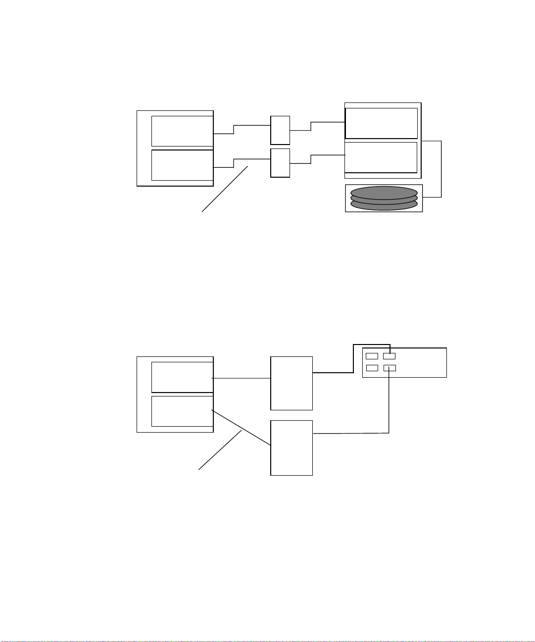
Host
Host adapter
Host adapter
Switches
Sun StorEdge A3500FC controller module
Controller A
FC-AL port
Controller B
FC-AL port
SCSI x 5
Fibre-optic cables
FIGURE 2 Example: Single Host Connected to One Sun StorEdge A3500FC Controller
Drive tray x 5
Module Using Switches
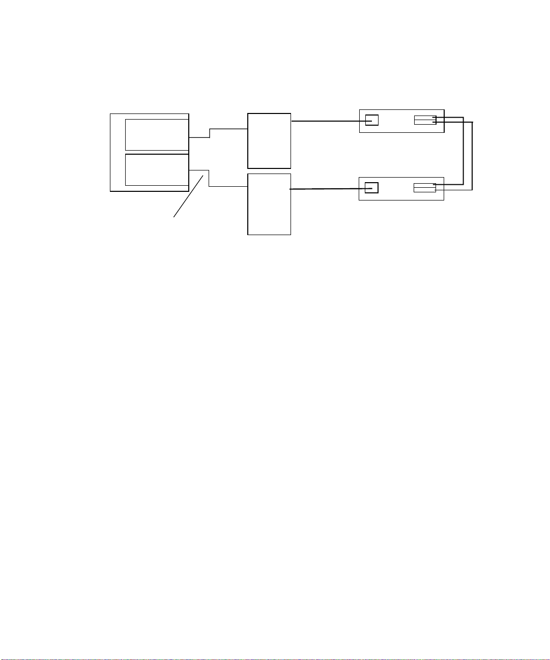
Sun StorEdge A5200 controller module
Host
Switches
IBA
IBB
Host adapter
Host adapter
Fiber-optic cables
FIGURE 3 Example: Single Host Connected to One Sun StorEdge A5200 Controller
Module Using Switches
Sun StorEdge Network FC Switch-8 and Switch-16 Field Troubleshooting Guide—April, 2001 7
Page 20
Host
Host adapter
Host adapter
Fiber-optic cables
Sun StorEdge T3 Partner Pair
Switches
FIGURE 4 Example: Single Host Connected to One Sun StorEdge T3 Partner Pair Using
Switches
8 Sun StorEdge Network FC Switch-8 and Switch-16 Field Troubleshooting Guide • April, 2001
Page 21
Sun StorEdge A3500FC controller module 4
Controller A
FC-AL port
Controller B
FC-AL port
SCSI x 5
Host
Host adapter
Host adapter
switches
Drive tray x 5
StorEdge A3500FC controller module
Controller A
FC-AL port
Controller B
FC-AL port
SCSI x 5
Drive tray x 5
StorEdge A3500FC controller module
Controller A
FC-AL port
Controller B
FC-AL port
SCSI x 5
Drive tray x 5
FIGURE 5 Example: Single Host to Multiple A3500-FC Controller Modules Using
switches
Sun StorEdge Network FC Switch-8 and Switch-16 Field Troubleshooting Guide—April, 2001 9
Page 22
Sun StorEdge A5200 controller modules - 3
Host
Host adapter
Host adapter
FIGURE 6 Example: Single Host to Multiple A5200 Controller Modules Using switches
switches
IBA
IBB
IBA
IBB
IBA
IBB
10 Sun StorEdge Network FC Switch-8 and Switch-16 Field Troubleshooting Guide • April, 2001
Page 23
Sun StorEdge T3 Partner Pairs - 2
Host
Host adapter
Host adapter
FIGURE 7 Example: Single Host to Two StorEdge T3 Partner Pairs using switches
switches
Sun StorEdge Network FC Switch-8 and Switch-16 Field Troubleshooting Guide—April, 2001 11
Page 24
Sun StorEdge T3 Partner Pairs (4)
Host
Host adapter
Host adapter
Switches
2
3
6
1
7
2
1
3
6
7
FIGURE 8 Example: Single Host Connected to Multiple StorEdge T3 Partner Pairs,
Using Switches
12 Sun StorEdge Network FC Switch-8 and Switch-16 Field Troubleshooting Guide • April, 2001
Page 25
Host
Host adapter
Host adapter
Multi-Host
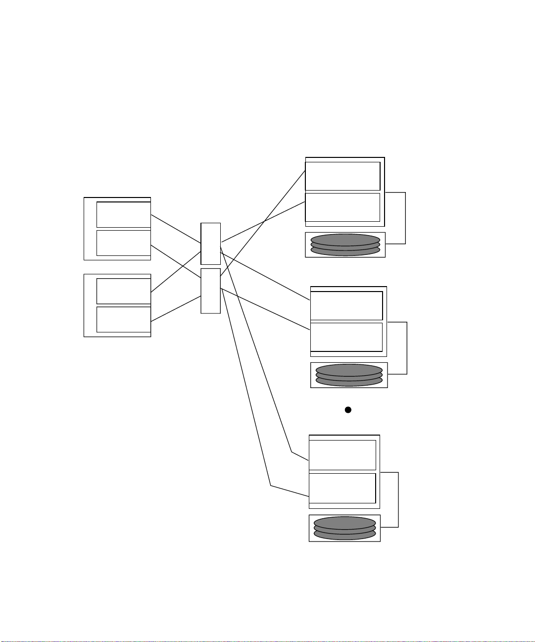
FIGURE 9 shows an example of a multi-host configuration: two hosts connected
through fiber-optic cables to two Sun StorEdge A3500FC controller modules using
switches.
A3500FC controller modules -4
Controller A
FC-AL port
switches
Controller B
FC-AL port
SCSI x 5
Host
Host adapter
Host adapter
A3500FC controller module
Drive tray x 5
Controller A
FC-AL port
Controller B
FC-AL port
Drive tray x 5
A3500FC controller module
Controller A
FC-AL port
Controller B
FC-AL port
Drive tray x 5
SCSI x 5
SCSI x 5
FIGURE 9 Two Hosts Connected to up to Four Sun StorEdge A3500-FC Controller
Modules using switches
Sun StorEdge Network FC Switch-8 and Switch-16 Field Troubleshooting Guide—April, 2001 13
Page 26
Host
Sun StorEdge A5200 controller modules - 3
Host adapter
Host adapter
Host
Host adapter
Host adapter
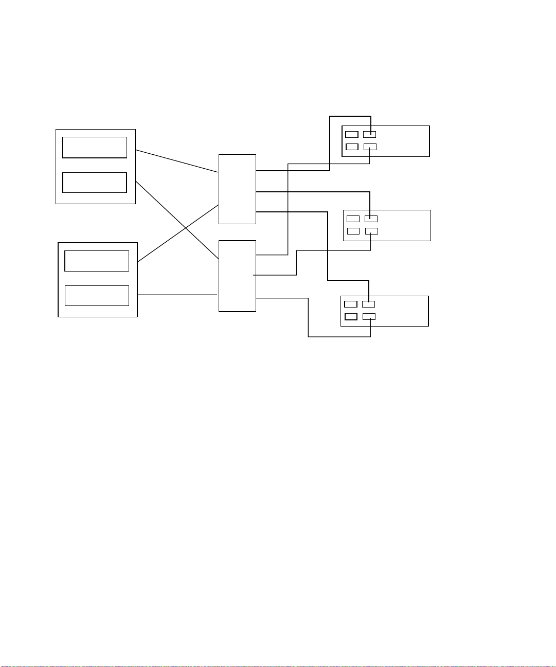
FIGURE 10 Example: Two Hosts Connected to Three Sun StorEdge A5200 Controller
switches
Modules using Switches
IBA
IBB
IBA
IBB
IBA
IBB
14 Sun StorEdge Network FC Switch-8 and Switch-16 Field Troubleshooting Guide • April, 2001
Page 27
Host
Sun StorEdge T3 Partner Pairs (4)
Host adapter
Host adapter
Host
Host adapter
Host adapter
Switches
SL Zone 1
1
2
3
6
8
7
SL Zone 2
SL Zone 3
1
3
8
SL Zone 4
2
6
7
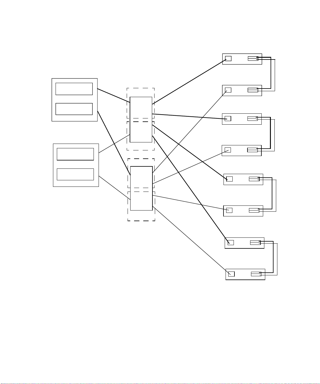
FIGURE 11 Example: Two Hosts Connected to Four Sun StorEdge T3 Partner Pairs Using
Switches
Sun StorEdge Network FC Switch-8 and Switch-16 Field Troubleshooting Guide—April, 2001 15
Page 28

Diagnostic Tools
Note – Ensure that all the systems are running Solaris 8 (10/00 or later).
The tools available for troubleshooting:
Switch
■ Sun StorEdge Network FC switch 2.0 GUI
Host
■ Sun StorEdge StorTools 4.x (offline/online)
■ Sun StorEdge RASAgent 1.1
■ Explorer 3.4
■ Sun StorEdge T3 array extractor script
Storage
■ CM 2.1 - Sun StorEdge T3 array
■ RAID Manager 6.2.2 - Sun StorEdge A3500-FC array
■ Sun StorEdge StorTools 4.x - Sun StorEdge A5200 array
Hardware Tools
A loopback cable is required when you use Sun StorEdge StorTools 4.x CLI
stexpert.
16 Sun StorEdge Network FC Switch-8 and Switch-16 Field Troubleshooting Guide • April, 2001
Page 29

Helpful Failure Information
The following information should be gathered and reviewed before you start any
troubleshooting effort. The information you gather may point you in the right
direction or support other failure data.
■ /var/adm/messages
■ Sun StorEdge RASAgent 1.1 e-mail messages
■ Weblog.file
■ Explorer
■ LED indicators
■ Counters
■ Customer input
■ Component Manager alert messages
■ Sun StorEdge StorTools 4.x logs (/var/opt/SUNWvtsst/logs)
■ Capture utility output
Sun StorEdge Network FC Switch-8 and Switch-16 Field Troubleshooting Guide—April, 2001 17
Page 30
Power
Switch
FC Switch LEDs and Back Panel Controls
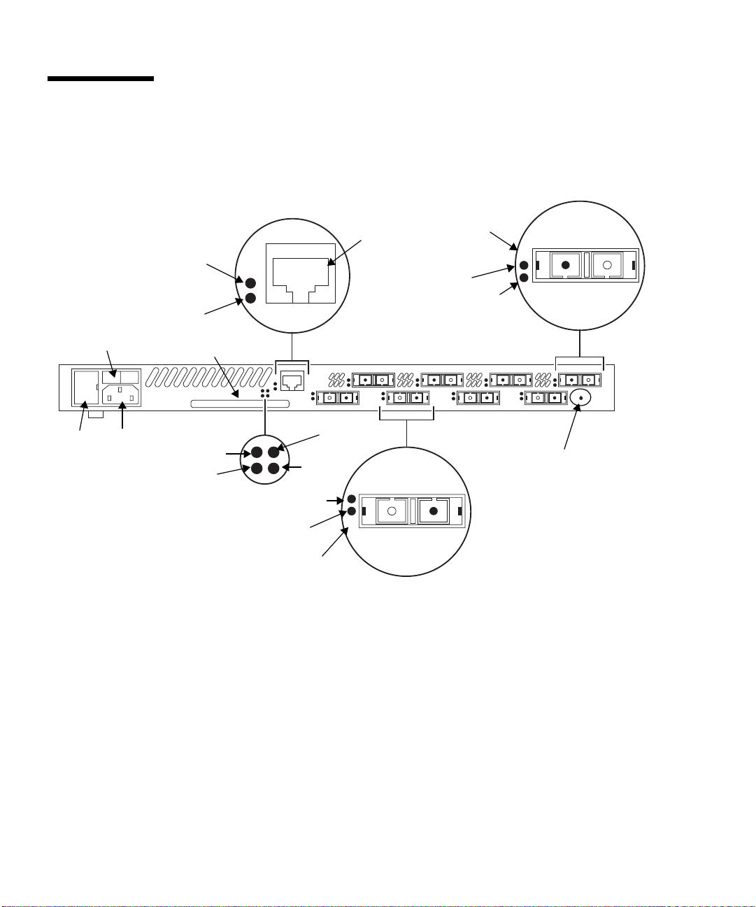
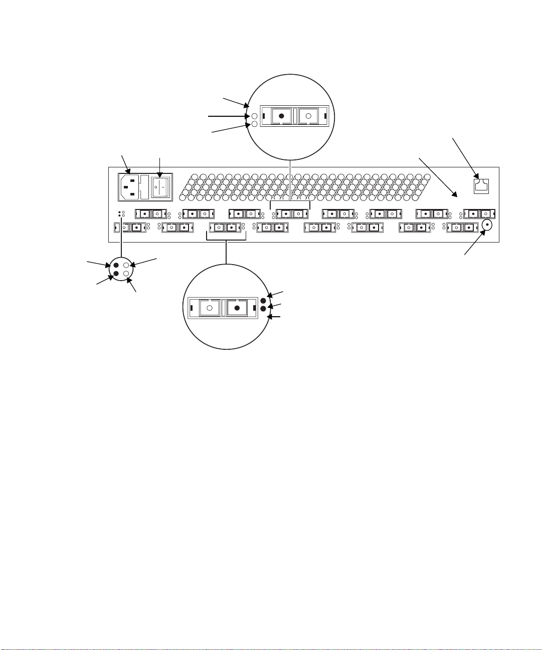
FIGURE 12 and FIGURE 13 identify the parts of the switch chassis back. Port numbers
are marked on the chassis.
Port
Number
Rx Tx
8
Activity LED
(Ethernet)
Link Status LED
(Ethernet)
MAC Address
Label
Switch Management
Connector (RJ45)
Traffic LED
(Yellow)
Logged-In LED
(Green)
Rx Tx
2 4 6 8
Fuses
xx-xx-xx-xx-xx-xx
Switch Logic Power
ACInput
Power
Plug
Over
Temperature
LED (Red)
Fan Fail
LED (Red)
FIGURE 12 Chassis Back (8-Port Switch)
Good LED (Green)
Heartbeat LED
Logged-In LED
(Green)
Traffic LED
(Yellow)
Port Number
1 3
Tx Rx
(Yellow)
3
Tx Rx
5
7
Test Mode Switch
18 Sun StorEdge Network FC Switch-8 and Switch-16 Field Troubleshooting Guide • April, 2001
Page 31
AC Power
Plug
Port Number
Traffic LED
(Yellow)
Logged-In
LED (Green)
Power Switch
RX TX
8
Fibre Channel Port
MAC Address
Label
Switch
Management
Connector
(RJ45)
Over
Temperature
LED
(RED)
Fan Fail
LED (RED)
Rx Tx
1 3 5 7 9 11 13 15
Tx Rx
Switch Logic
Power Good
LED (Green)
42 8
Heartbeat
LED
(Yellow)
TX
6 1210 1614
Logged-In LED
RX
(Green)
Traffic LED (Yellow)
Port Number
5
FIGURE 13 Chassis Back (16-Port Switch)
xx-xx-xx-xx-xx-xx
Force
PROM
Button
Sun StorEdge Network FC Switch-8 and Switch-16 Field Troubleshooting Guide—April, 2001 19
Page 32

Power Switch
“Chassis Back (8-Port Switch)” on page 18 and “Chassis Back (16-Port Switch)” on
page 19 shows the location of the power switch. The power switch is a rocker switch.
Press the right side (labeled 1) to turn it ON; press the left side (labeled 0) to turn it
OFF.
When you press the power switch and turn it ON, there is a two-second delay before
the fans start and the Power Good LED on the back of the chassis illuminates. The
Power Good light indicates that the switch logic is receiving power within the
proper voltage range.
Back Panel LEDs
LEDs visible through lenses in the back of the chassis indicate chassis and port
status. During a reset operation (for about two seconds at the beginning of poweron) all LEDs are forced ON. The following definitions are valid following the POST
when the POST finds no errors. See “Diagnosing and Troubleshooting the Switch”
on page 23 for more information about the heartbeat LED error codes.
Heartbeat LED (Yellow)
The heartbeat LED indicates the status of the internal switch processor and the
results of POSTs run at power-on.
Following a normal power-on, the heartbeat LED blinks about once per second to
indicate that the switch has passed the POSTs and the internal switch processor is
running.
See “Diagnosing and Troubleshooting the Switch” on page 23 for more information
about heartbeat LED error codes.
Switch Logic Power Good LED (Green)
This LED is ON when the power supply is delivering power within normal limits to
the switch logic (the power switch must be ON).
Fan Fail LED (RED)
This LED is normally OFF. It comes ON only when the speed of a fan drops below
operational level.
20 Sun StorEdge Network FC Switch-8 and Switch-16 Field Troubleshooting Guide • April, 2001
Page 33

Over Temperature LED (Red)
This LED is normally OFF. The over temperature LED lights to indicate that the air
temperature inside the switch has exceeded a certain limit. If this LED lights, inspect
the following:
■ Ambient air temperature: maximum 40°C (104° F)
■ Proper clearance: 163 mm (6.5”) back, right side, and front
■ Fan Operation
■ Power supply operation
Logged-In LED (Green)
Each port has its own Logged-In LED. The Logged-In LED indicates the logged-in or
initialization status of the connected device or loop of devices. Initially (immediately
after the switch completes the POST successfully, the switch holds all Logged-In
LEDS OFF (no light). Each remains OFF until the port and its attached devices are
able to perform a loop initialization (LIP) successfully. Following a successful LIP on
a given port, the switch turns the Logged-In LED ON (lit) for that port. This shows
that the port is properly connected and able to communicate with its attached
devices. The LED for this port remains ON as long as the port is initialized.
If the established link is broken (a fiber opens or the connected port goes out of
service), the Logged-In LED is shut OFF. If the link is replaced or the connected port
comes back into service, the port and its attached devices try to regain initialized
status. If the initialization is re-established, the switch turns the Logged-In LED back
ON and communication continues.
Traffic LED (Yellow)
Each port has its own port traffic LED. The traffic LED for a particular port is ON
when Class 2 or 3 frames are entering or leaving the port. The switch turns the LED
ON for 50 milliseconds for each frame, so you should be able to see it for one frame.
This LED does not light for frames following an arbitrated loop in bypass mode.
Sun StorEdge Network FC Switch-8 and Switch-16 Field Troubleshooting Guide—April, 2001 21
Page 34

AC Input Power Connector and Fuses
A standard 3-wire computer-type AC power cable (supplied with the switch)
connects between the AC input power connector and an AC outlet. See
and FIGURE 13.
An input fuse holder is incorporated into the AC input power connector assembly. It
holds two input fuses.
Switch Management Connector
The switch management connector is a 10/100BASE-T Ethernet interface that
provides a connection to a management station. See
Note – A sticker on the back of the chassis contains the MAC Address. The MAC
Address is used for the physical address for ethernet communication.
FIGURE 12 and FIGURE 13.
Ethernet LEDs
Link Status
FIGURE 12
The green LINK status LED lights only when the Ethernet interface establishes an
electronic link. See
FIGURE 12 and FIGURE 13.
Activity
The yellow Activity LED lights when the interface is transmitting data to the
network or receiving data from the network.
22 Sun StorEdge Network FC Switch-8 and Switch-16 Field Troubleshooting Guide • April, 2001
Page 35

Diagnosing and Troubleshooting the Switch
This section provides information for diagnosing and troubleshooting problems with
the switch.
■ Power Checks and Troubleshooting help you solve AC power and Power Supply
problems.
■ Power-On-Self-Test (POST) checks the condition of the Switch, with the exception
of the GBICs.
■ Cable Continuity tests for open fibers in the cable network.
Power Checks and Troubleshooting
The following procedure assumes the Power Good LED does not light.
Check that:
■ The power switch is in the ON (l) position.
■ The AC power outlet has the proper voltage.
■ The power cable has continuity and is plugged into both the AC power outlet and
the switch chassis.
■ The input fuses are good.
■ If the Logged-in LED is off and the device attached to the port is a host, be sure
the host is powered on and booted.
■ If the Logged-in LED is off and the device attached to the port is a storage unit, be
sure it is powered on and is operating normally. You can verify the status of your
array from the array’s front LEDs and from RM6. Refer to the Sun StorEdge array
manuals for information.
Power-On-Self-Test (POST)
At startup, the switch runs a series of Power-On-Self-Test diagnostics. These POST
diagnostics check for proper switch operation, excluding the GBICs. If no fatal errors
are encountered, the switch becomes operational.
Sun StorEdge Network FC Switch-8 and Switch-16 Field Troubleshooting Guide—April, 2001 23
Page 36

During the POST, the switch logs any errors encountered. Some POST errors are
fatal; others are non-fatal. A fatal error disables the switch so that it does not
operate. A non-fatal error allows the switch to operate, but with some decrease in
performance until the problem is corrected.
■ A PROM checksum failure is an example of a fatal error. It indicates that the
PROM firmware is corrupt, and the switch does not operate.
■ A failure associated with a Fibre Channel port is an example of a non-fatal error.
The switch can isolate the bad port while the other ports continue to operate.
Note – In the following POST error descriptions, note that some errors result in a
switch that is operable, but in a degraded way (non-fatal errors). Other errors result
in a switch that is not operable (fatal errors). If the problem is non-fatal, you can run
in a degraded mode until the problem is fixed.
When POST is complete and errors are encountered, the switch uses the heartbeat
LED to blink an error code that describes the first fatal error encountered. The LED
blinks in a pattern relating to the failure, pauses, and then restarts the same blinking
pattern.
The switch then reads its error log, and if it has encountered non-fatal errors that
affect one or more ports (with remaining ports operable), it disables the bad ports
and blinks the Logged-in LED of the affected port or ports. If the errors is non-fatal
but does not affect a single port or group of ports, only the heartbeat LED blinks an
error code. In all cases, the switch displays the POST error indications until you
power it off. For example:
■ If the POST encounters a PROM checksum error, the entire switch is inoperable.
The heartbeat LED blinks the error code for the fatal POROM checksum error. The
entire switch is down, and no port Logged-in LEDs are lit because the problem
does not affect a port or ports.
■ If the POST encounters a bus error, the switch may operate in a degraded mode
because it has multiple buses. It can operate with one or more buses in operation,
but some normal processing functions, such as in-order delivery, may be
adversely affected. The heartbeat blinks the error code for the non-fatal bus error.
The switch may operate more slowly, but no port Logged-in LEDs are lit because
the problem does not affect the ports.
■ If the POST encounters a port error, the switch may operate with the remaining
ports. The heartbeat blinks an error code for the non-fatal port error. The switch
disables the failing port or ports and blinks their Logged-in LEDs.
■ If the heartbeat LED is blinking normally and you cannot access the switch via
the SANSurfer GUI, check the IP address and verify that it is set correctly. Refer to
the Sun Switch Management Installer ’s/User’s Manual for instructions on how to
check and set the IP address. Also check the ethernet cable.
24 Sun StorEdge Network FC Switch-8 and Switch-16 Field Troubleshooting Guide • April, 2001
Page 37
The POST diagnostic program performs the following basic tests:
■ Checksum tests on the Boot firmware located in a PROM and the main switch
firmware located in FLASH memory.
■ Functional hardware tests on internal switch memory.
■ Various read/write register and loopback data-path tests on the switch logic
board.
■ Frame bus and auto route logic tests
■ Switch management port logic
■ Arbitrated loop tests
Using the Test Mode Switch
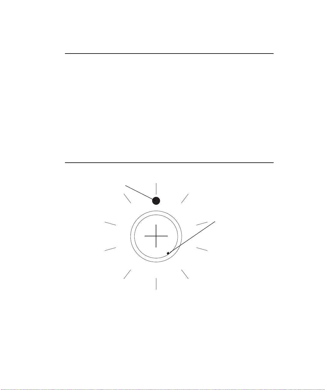
The test mode switch is a small rotary switch located on the back of the switch
chassis as shown in
switch chassis to perform the following functions:
■ Normal Operation: Performs POST diagnostics once at the time of startup and
then proceeds to normal operation.
■ Force PROM: Used to gain access to the PROM when flash memory or the
resident configuration file is disabled.
The test mode switch position determines which functions are performed when the
switch chassis is powered on. See
positions. Normal operation is indicated by the alignment of the small notch on the
test mode switch with the dot on the faceplate.
FIGURE 12 and FIGURE 13. The test mode switch enables the
FIGURE 14 for test mode switch functions and
Caution – Use the test mode switch on the back panel while performing
maintenance tasks only. Data may be corrupted if the test mode switch is used while
the switch chassis is operating.
Sun StorEdge Network FC Switch-8 and Switch-16 Field Troubleshooting Guide—April, 2001 25
Page 38
Front Panel Switch Modes
The following are the settings for the 10-position rotary switch:
0 Normal operations
1 Continuous test
2 Test bypass
3 Operator test
4 Normal operation/initial test with force PROM mode
5 Continuous test with force PROM mode
6 Test bypass with force PROM
7 Operator test with force PROM
8 Normal operation/initial test with watchdog timer disabled
9 Continuous test with watchdog timer disabled
Dot on Faceplate
Notch on Switch
(shown in Force
PROM position)
Force PROM
(4 Clicks)
FIGURE 14 Test Mode Switch Functions and Positions
26 Sun StorEdge Network FC Switch-8 and Switch-16 Field Troubleshooting Guide • April, 2001
Page 39
▼ Troubleshooting Test Mode Switch Functions
1. Use a small screwdriver to change the test mode switch positions.
Use the normal position as reference and count the number of clicks (one click per
position). These clicks are not audible and are best detected by touch.
2. Isolate the switch chassis.
Data may be lost or corrupted if the test mode switch is used while data is being
transmitted.
3. Using a small screwdriver, rotate the test mode switch to the desired position.
4. Turn the power off and then back on to reset the switch chassis.
5. Observe the heartbeat LED for error codes (five blinks is normal when in the Force PROM mode).
Correct conditions or reconfigure the switch as needed.
6. Return the test mode switch to the normal position, aligning the small notch with
the dot on the faceplate.
7. Turn the switch off and then back on to reset the switch chassis.
Heartbeat LED Blink Patterns
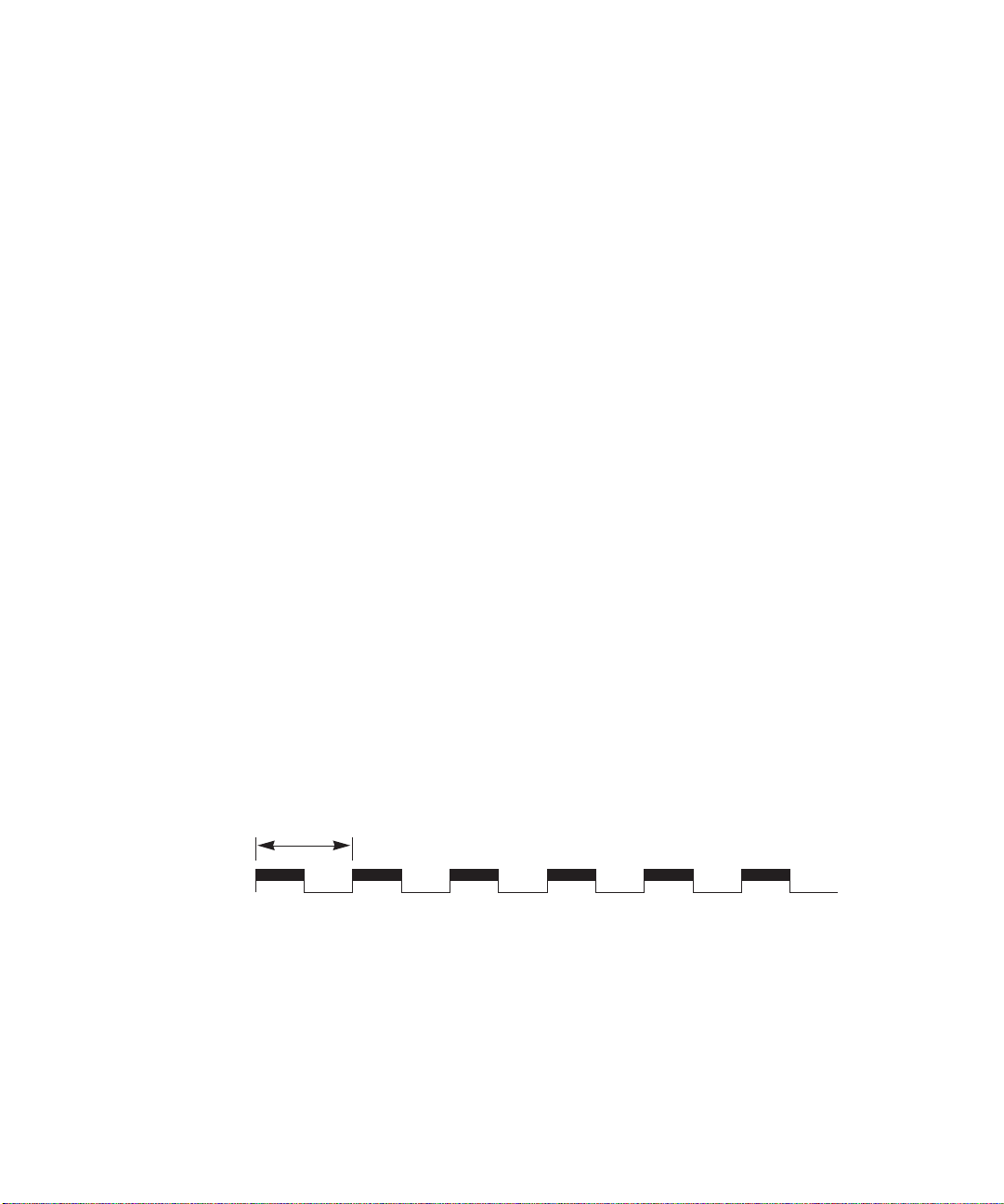
Normal (all pass)
If all POST diagnostics pass, the switch goes to normal operation and the heartbeat
LED blinks at a steady rat of one blink per second.
1 sec.
FIGURE 15 Heartbeat LED—Normal
Sun StorEdge Network FC Switch-8 and Switch-16 Field Troubleshooting Guide—April, 2001 27
Page 40
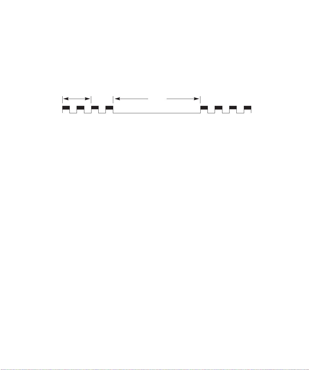
Failure Blink Patterns
The heartbeat LED indicates the error with a series of blinks, a three-second pause,
and then the same series of blinks. The number of blinks between the three-second
pause indicates the error. The blinks occur at about twice the speed of the normal
heartbeat.
1 sec.
FIGURE 16 Heartbeat LED—Failure Blink Patterns
3 sec.
PROM Checksum Failure (One Blink)
The switch is not operable.
This checksum test of the PROM verifies the integrity of the PROM data. A failure
indicates the PROM data is corrupted. The heartbeat LED blinks once between the
three-second pauses. No port Logged-in LEDs blink.
RAM Failure (Two Blinks)
The switch is not operable.
This test verifies the data and address buses to the SRAM and verifies SRAM
integrity. A failure indicates that the data bus, address bus, or SRAM is failing. The
heartbeat LED blinks twice between the three-second pauses. No port Logged-in
LEDs blink.
Flash Checksum Failure/Switch Management Port (Ethernet) Tests Good (Three Blinks)
The switch is not operable.
The flash checksum test verifies the integrity of the flash data. If the flash data is
corrupt, the POST next checks the Switch Management port to find out if it is
functional. The Switch Management port is the load path for loading new flash data.
If the Switch Management ports tests good, the heartbeat LED blinks three times
between the three-second pauses. No port Logged-in LEDs blink.
28 Sun StorEdge Network FC Switch-8 and Switch-16 Field Troubleshooting Guide • April, 2001
Page 41

You may load new flash control code via the Switch Management port. See the
Switch Management manual for a description of how to load new flash code.
Flash Checksum Failure/Switch Management port (Ethernet) Failure (Four Blinks)
The switch is not operable.
The flash checksum test verifies the integrity of the flash data. If the flash data is
corrupt, the POST checks the Switch Management port to find out if it is functional.
The Switch Management port is the load path for loading new flash data. If the
Switch Management ports tests bad, the heartbeat LED blinks four times between
the three-second pauses. No port Logged-in LEDs blink. This means that the flash
control code is corrupt and the Switch Management port may not operate well
enough to load new flash code.
Force PROM Mode in Effect (Five Blinks)
This is an alarm.
Five blinks indicate that the processor is reading the default configuration from
PROM instead of from flash memory.
The test mode switch is in the force PROM position. This error never occurs unless
you are using the force PROM button. The heartbeat LED blinks five times between
the three-second pauses.
Switch ASIC Test Failure (Six Blinks)
The switch is not operable.
The switch ASIC test verifies the base functionality of each switch ASIC, including
the control port interface and all functions performable with the confines of an
individual ASIC. A failure indicates a faulty switch ASIC. The heartbeat LED blinks
six times between three-second pauses. The switch disables the ports associated with
the bad ASIC and blinks the ports’ Logged-in LEDs. An ASIC that fails this test
could affect the operation of the remaining ports.
Sun StorEdge Network FC Switch-8 and Switch-16 Field Troubleshooting Guide—April, 2001 29
Page 42

GBIC Bypass Port Loopback Test Failure (Seven Blinks)
The switch is operable.
The GBIC bypass port loopback test verifies (on a port-by-port basis) the ability of
each switch ASIC to loop data out through the Serdes chip on a port and back to the
ASIC control port (bypassing the GBIC). A failure indicates either a faulty switch
ASIC or an ASIC-to-Serdes interface problem. the heartbeat LED blinks seven times
between three-second pauses. The switch disables the failing port or ports and
blinks their Logged-in LEDs. The ports whose Logged-in LEDs are not blinking have
passed the test and are all usable.
Fibre Channel Port Loopback Test Failure (Eight Blinks)
Note – This test runs in Continuous Test only. Continuous Test is controlled by the
test mode switch. Use this test only under the direction of customer support, which
will tell you how to activate the test.
The switch is not operable while in continuous test.
In continuous test mode, the switch fibre channel port loopback test verifies the
ability of each switch ASIC to loop data out through each fibre channel port, through
a loopback plug, and back to the ASIC control port. In order to accomplish this test,
you must attach a loopback plug to each GBIC as you test it.
▼ To Test
1. Place the chassis into Continuous Test.
2. Remove all GBICs from the chassis, except the one you want to test.
The GBIC under test may be in any port. The Continuous Test skips all empty ports.
3. Insert a loopback plug into the GBIC.
4. Cycle the chassis power to cause a reset.
5. After a few seconds of testing, if the heartbeat LED is blinking about once per
second (normal), the GBIC passes the test. If the heartbeat LED blinks the eightblink error code, the GBIC failed.
Repeat steps 2 through 5 to test all the GBICs, one at a time.
6. When all the tests are complete, place the test mode switch back in the ‘Normal
Run’ position (small dot on the end of the shaft pointing straight up).
7. Cycle the chassis power to cause a reset.
30 Sun StorEdge Network FC Switch-8 and Switch-16 Field Troubleshooting Guide • April, 2001
Page 43

Switch Bus Test Failure (Nine Blinks)
The switch is not operable.
The switch bus test verifies the ability of the switch ASICs to communicate with each
other via the buses that interconnect the ASICs. A failure indicates an inability of an
ASIC pair to communicate over one or more buses. The heartbeat LED blinks nine
times between three-second pauses. No port Logged-in LEDs blink.
Switch Auto-Route Test Failure (10 Blinks)
The switch is operable.
The switch auto-route test verifies the auto-route capability of individual ports to
route frames to the other ports in the chassis. The heartbeat LED blinks 10 times
between three-second pauses. the switch disables the failing ports or port-pairs and
blinks their Logged-in LEDs.
The ports whose Logged-in LEDs are not blinking have passed the test.
Eleven and Twelve Blinks—Not Used
Arbitrated Loop Test Failure (13 Blinks)
The switch is operable.
The arbitrated loop test verifies the ability of the arbitrated loop ports to initialize
properly. The heartbeat LED blinks 13 times between three-second pauses. The
switch disables the failing ports and blinks their Logged- LEDs.
The ports whose Logged-in LEDs are not blinking have passed the test.
Switch Management Port Failure (14 Blinks)
The switch is operable.
The switch management port test verifies the functionality of the Ethernet data bus.
A failure indicates that communication over the Ethernet port will probably be
adversely affected. The heartbeat LED blinks 14 times between three-second pauses.
No port Logged-in LEDs blink.
Sun StorEdge Network FC Switch-8 and Switch-16 Field Troubleshooting Guide—April, 2001 31
Page 44

NVRAM Test Failure (15 Blinks)
The switch is not operable.
The Non-Volatile Memory (NVRAM) test verifies the status of the NVRAM battery
(not low), performs a checksum on any existing data, and performs a data
write/read test on the unused areas of the NVRAM. A test failure in any the these
three tests causes the heartbeat LED to blink 15 times between three-second pauses.
Hung Flash Control Code
The switch is not operable.
If the Power Good LED is lit and the heartbeat LED and the remaining front-panel
LEDs blink in unison, the flash control code running the processor is hung.
Complete Failure
The switch is not operable.
If the Power Good LED is lit and the heartbeat LED does not blink at all (always ON
or always OFF) the switch is not operable.
Cable Continuity Tests
When there is a problem communicating over a particular link and both the switch
and the connected device pass their respective tests, check the continuity of the
cables. Run the Sun StorEdge StorTools 4.x PCI FC-100 board test ( switchtest)
while using the SW port option. Depending on the configuration, this may be an
offline activity.
32 Sun StorEdge Network FC Switch-8 and Switch-16 Field Troubleshooting Guide • April, 2001
Page 45

Switch Counter Information
Sun Engineering is currently investigating how counters can be used to help isolate
failure. At this time, counter data should be used only as supporting data. Do not use
this data as the primary source in the troubleshooting process.
General points to keep in mind when viewing counters follow.
■ Quickly increasing or abnormally high counter values may indicate a problem.
■ A LIP that occurs on one port in a zone propagates to all the ports that have
devices attached to them in the same zone. The LIP counter is incremented on all
those ports.
■ Normal activity may also increase counter values.
■ Counters increment on power cycles.
Running the QLC test within Sun StorEdge StorTools 4.x increments the following
counters:
■ In frames
■ Out frames
■ Link failure
■ Sync losses 100ms
■ Invalid tx words rec
■ LIP total received
■ LIP F7F7
■ LIP F8F7
■ AL Init Attempts
■ Sync Loss
■ LIP during Init
To view any counter, use the Sun StorEdge Network FC Switch 2.0 GUI (see
FIGURE 17 on the following page.) You can view the counters non-disruptively.
Sun StorEdge Network FC Switch-8 and Switch-16 Field Troubleshooting Guide—April, 2001 33
Page 46
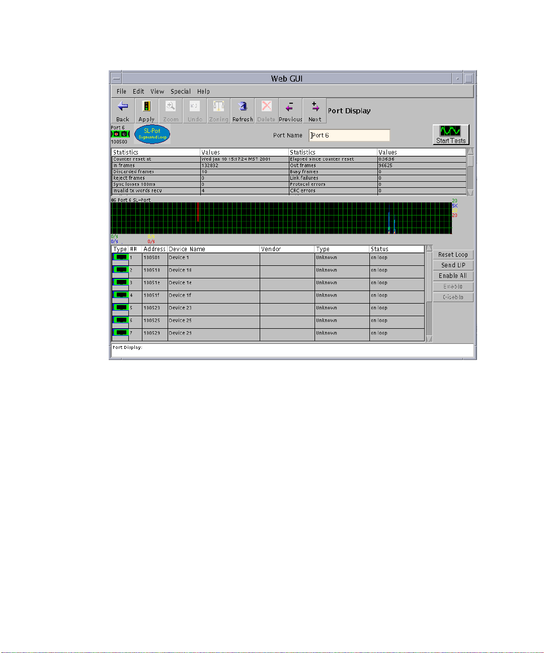
FIGURE 17 Port Display
TABLE 4 on the following page describes the counters from the Port Display window.
34 Sun StorEdge Network FC Switch-8 and Switch-16 Field Troubleshooting Guide • April, 2001
Page 47

Counter Descriptions
TABLE4 Port Display Window Counters
Counter Name
(in port display) Description
Address ID errors Number of address identifiers (S_ID, D_ID) found to be in error.
AL Init Attempts Number of times the port entered the initialization state.
AL Init Errors Number of times the port entered initialization and the initialization
failed.
Busy frames Number class 2 and class 3 fabric busy (F_BSY) frames generated by
this port in response to incoming frames. This usually indicates a
busy condition on the fabric or N_port that is preventing delivery of
this frame.
Counter reset at Show the time and date of the last time the switch was reset.
CRC errors Number of invalid Cyclic Redundancy Check (CRC) frames
detected.
Delimiter errors Number of delimiter errors detected. Delimiters, such as SOFc3 (star
of frame, class 3), EOFn (end of frame), or others are improper or
invalid.
Discarded frames Number of class 2 and class 3 sequences that were discarded by this
port. A sequence can be discarded because of detection of a missing
frame (based on SEQ_CNT), detection of and E_D_TOV timeout,
receiving a reject frame, receiving frames for a stopped sequence, or
other causes.
Elapsed since
counter reset
In frames Number of class 2 and class 3 frames received by this port.
Invalid tx words
recv
Laser Faults Number of times a laser fault was detected.
LIP Flow Cntrl
Errors
Link Failures Number of optical link failures detected by this port. A link failure
Link reset in Number of link reset primitives received from an attached device.
Length of time that has elapsed since the last switch reset was
performed.
Number of invalid transmission words detected during decoding.
Decoding is from the 10-bit characters and special K characters.
This is a switch internal error condition (for factory use only).
ia loss of synchronization for a period of time greater than the value
of R_fT_fTOV or by loss of signal while not in the offline state. A
loss of signal causes the switch to attempt to re-establish the link. If
the link is not re-established by the time specified by R_T_TOV, a
link failure is counted. A link reset is performed after a link failure.
Sun StorEdge Network FC Switch-8 and Switch-16 Field Troubleshooting Guide—April, 2001 35
Page 48

TABLE4 Port Display Window Counters
Counter Name
(in port display) Description
Link reset out Number of link reset primitives sent from this port to an attached
port.
LIP AL_PD AL_PS Number of F7, AL_PS LIPs, or AL_PD (vendor specific) resets
performed.
LIP during INit Number of times the switch received a LIP while it was already in
the initialization state.
LIP F7 AL_PS This LIP is used to re initialize the loop. An L_port, identified by
AL_PS, may have noticed a performance degradation and is trying
to restore the loop.
LIP F7F7 A loop initialization primitive frame used to acquire an AL_PA.
LIP F8 AL_PS This LIP denotes a loop failure detected by the L_port identified by
AL_PS.
LIP F8F7 Currently not used.
LIP Total Received Number of loop initialization primitive frames received.
LISM Failed The LISM primitive is used to select a temporary loop master for
initialization. This counter shows the number of times the switch
was unable to establish itself as the loop master.
LOF Timeout ELS Currently undefined.
LOF Timeouts Number of times the switch was unable to transmit a frame within
the R_T_TOV value.
Long Frame Errors Number of times a frame longer than the maximum frame size was
received.
Loss of Signal Number of signal losses detected for this port.
OLS in Number of offline sequences received. An OLS is issued for link
initialization, a Receive & Recognize Not_Operation (NOS) state, or
to enter the offline state.
OLS out Number of offline sequences issued by this port. An OLS is issued
for link initialization, a Receive & Recognize Not_Operation (NOS)
state, or to enter the offline state. The switch may issue an OLS to
perform offline diagnostics or to power down.
OPN Returns Number of times a device on the loop didn’t accept an open
primitive. This usually indicates a device error.
Out Frames Number of class 2 and class 3 frames transmitted by this port.
Protocol errors Number of primitive sequence protocol errors. An error indicates
that a sequence protocol violates the FC-2 signaling protocol.
36 Sun StorEdge Network FC Switch-8 and Switch-16 Field Troubleshooting Guide • April, 2001
Page 49

TABLE4 Port Display Window Counters
Counter Name
(in port display) Description
Reject Frames Number of frames, from devices, that have been rejected. Frames
can be rejected for any of a large number of reasons.
Reserved N/A
Retry LIPs Currently not used.
Short Frame Errors Number of times a frame shorter than 36 bytes was received.
SmoothingOverflow
Errors
Number of times that a violation of FC rules on the incoming signal
were detected. An example of a violation is an insufficient number
of idles received between frames.
Sync Loss Number of synchronization losses detected through reception of
invalid transmission words on the port.
Sync losses 100 ms Number of synchronization losses (>100 ms) detected by this port. A
loss of synchronization is detected by receipt of an invalid
transmission word.
Sun StorEdge Network FC Switch-8 and Switch-16 Field Troubleshooting Guide—April, 2001 37
Page 50
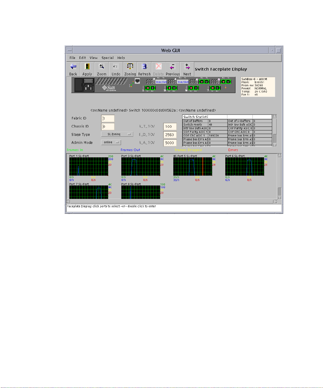
FIGURE 18 Web GUI
TABLE 5 on the following page lists the counter names and briefly describes them.
38 Sun StorEdge Network FC Switch-8 and Switch-16 Field Troubleshooting Guide • April, 2001
Page 51

TABLE5 Counter Names and Descriptions (Faceplate Window)
Counter Description
COF CRC ASIC 0
COF CRC ASIC 1
COF CRC ASIC 2*
Internal switch counter that tracks errors during frame
outputs from the specified ASIC. A non-zero value may
indicate an internal problem with the switch.
COF CRC ASIC 3*
COF Parity ASIC 0
COF Parity ASIC 1
COF Parity ASIC 2*
Parity error detected curing reading of the frame in the
CPORT OUt FIF) (COF) for the specified ASIC. A non-zero
value may indicate an internal problem with the switch.
COF Parity ASIC 3*
Frame bus Errs ASIC 0 Port 1
Frame bus Errs ASIC 0 Port 2
Frame bus Errs ASIC 0 Port 3
Errors detected in the data being sent over the frame bus
between ASICs. A non-zero value may indicate an internal
problem with the switch.
Frame bus Errs ASIC 0 Port 4
Frame bus Errs ASIC 1 Port 1
Frame bus Errs ASIC 1 Port 2
Frame bus Errs ASIC 1 Port 3
Frame bus Errs ASIC 1 Port 4
Frame bus Errs ASIC 2 Port 1
Frame bus Errs ASIC 2 Port 2
Frame bus Errs ASIC 2 Port 3
Frame bus Errs ASIC 2 Port 4
Frame bus Errs ASIC 3 Port 1
Frame bus Errs ASIC 3 Port 2
Frame bus Errs ASIC 3 Port 3
Frame bus Errs ASIC 3 Port 4
Internal Parity ASIC 0 Port 1
Internal Parity ASIC 0 Port 2
Internal Parity ASIC 0 Port 3
Parity error detected with data transfer internal to the
switch. A non-zero value may indicate an internal problem
with the switch.
Internal Parity ASIC 0 Port 4
Internal Parity ASIC 1 Port 1
Internal Parity ASIC 1 Port 2
Internal Parity ASIC 1 Port 3
Internal Parity ASIC 1 Port 4
Internal Parity ASIC 2 Port 1*
Internal Parity ASIC 2 Port 2*
Internal Parity ASIC 2 Port 3*
Internal Parity ASIC 2 Port 4*
Internal Parity ASIC 3 Port 1*
Internal Parity ASIC 3 Port 2*
Internal Parity ASIC 3 Port 3*
Internal Parity ASIC 3 Port 4*
Sun StorEdge Network FC Switch-8 and Switch-16 Field Troubleshooting Guide—April, 2001 39
Page 52

TABLE5 Counter Names and Descriptions (Faceplate Window)
Counter Description
Intr low Bus ASIC 0
Intr low Bus ASIC 1
Number of times a low buffer condition has occurred on
the specific ASIC.
Intr low Bus ASIC 2*
Intr low Bus ASIC 3*
Out of buffers Number of large frames that have been sent by this switch.
Out of s-buffers Number of small frames that have been sent by this switch.
Switch resets Number of times the switch has been reset since it was
manufactured.
* Available only for switches with more than 8 ports.
40 Sun StorEdge Network FC Switch-8 and Switch-16 Field Troubleshooting Guide • April, 2001
Page 53
Diagnostic Information and Isolation
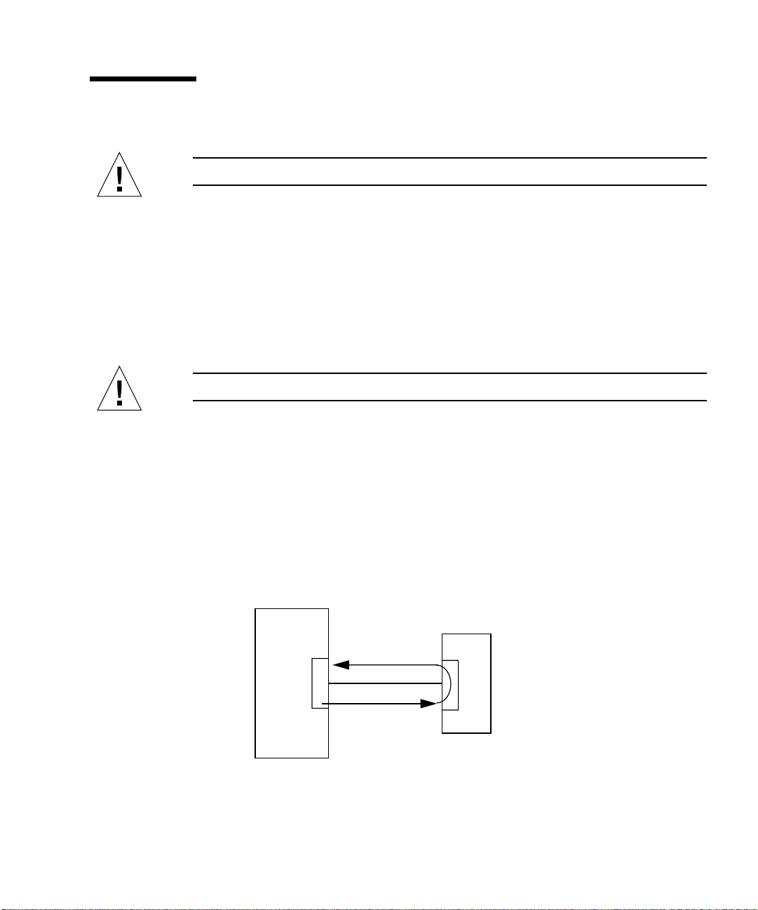
Caution – When running in online mode, deselect system board and HBA tests.
Sun StorEdge StorTools 4.x qlctest
You can run the Sun StorEdge StorTools 4.x PCI FC-100 Board Test (qlctest)or
SunVTS 4.1 qlctest to test the following portion of the SAN configuration:
■ HBA to switch and return path
FRUs tested: HBA, cable between HBA and switch, and Switch GBIC
Caution – Use the Sun StorEdge StorTools 4.x qlctest for offline testing only.
■ Do not run customer applications while running qlctest, as the qlctest will
take priority over customer data requests. The customer will be unable to access
data while qlctest is running.
■ Do not run other tests while qlctest is running. qlctest might cause other
tests to fail.
■ qlctest is an intervention mode test. No subtests can be selected unless
intervention is set.
For more information about Sun StorEdge StorTools 4.x qlctest, refer to the Sun
StorEdge StorTools User ’s Guide, Version 4.x, part number 806-6235-10.
Host
FIGURE 19 Sun StorEdge StorTools 4.x qlctest
Sun StorEdge Network FC Switch-8 and Switch-16 Field Troubleshooting Guide—April, 2001 41
Switch
Page 54
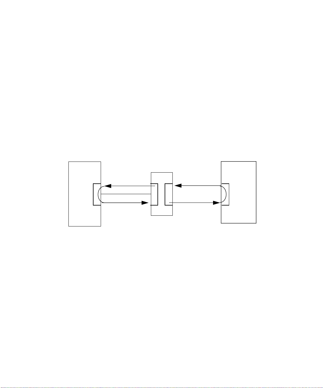
Sun StorEdge StorTools 4.x switchtest
You can run Sun StorEdge StorTools 4.x ( switchtest) or SANSurfer GUI Start Test
to test the following portion of the SAN configuration. Both tests can be run online.
■ Switch to HBA and return path when running on a selected port. See #1 in
FIGURE 20.
■ Switch to array and return path when running on a selected port. See #2 in
FIGURE 20.
FRUs Tested:
■ Cable between HBA and Switch
■ Cable between Switch and array
■ GBICs in switch
■ GBICs in array
#1 #2
Host
FIGURE 20 Sun StorEdge StorTools 4.x Switch Test or SANSurfer GUI Start Test
42 Sun StorEdge Network FC Switch-8 and Switch-16 Field Troubleshooting Guide • April, 2001
Switch
Storage
Page 55
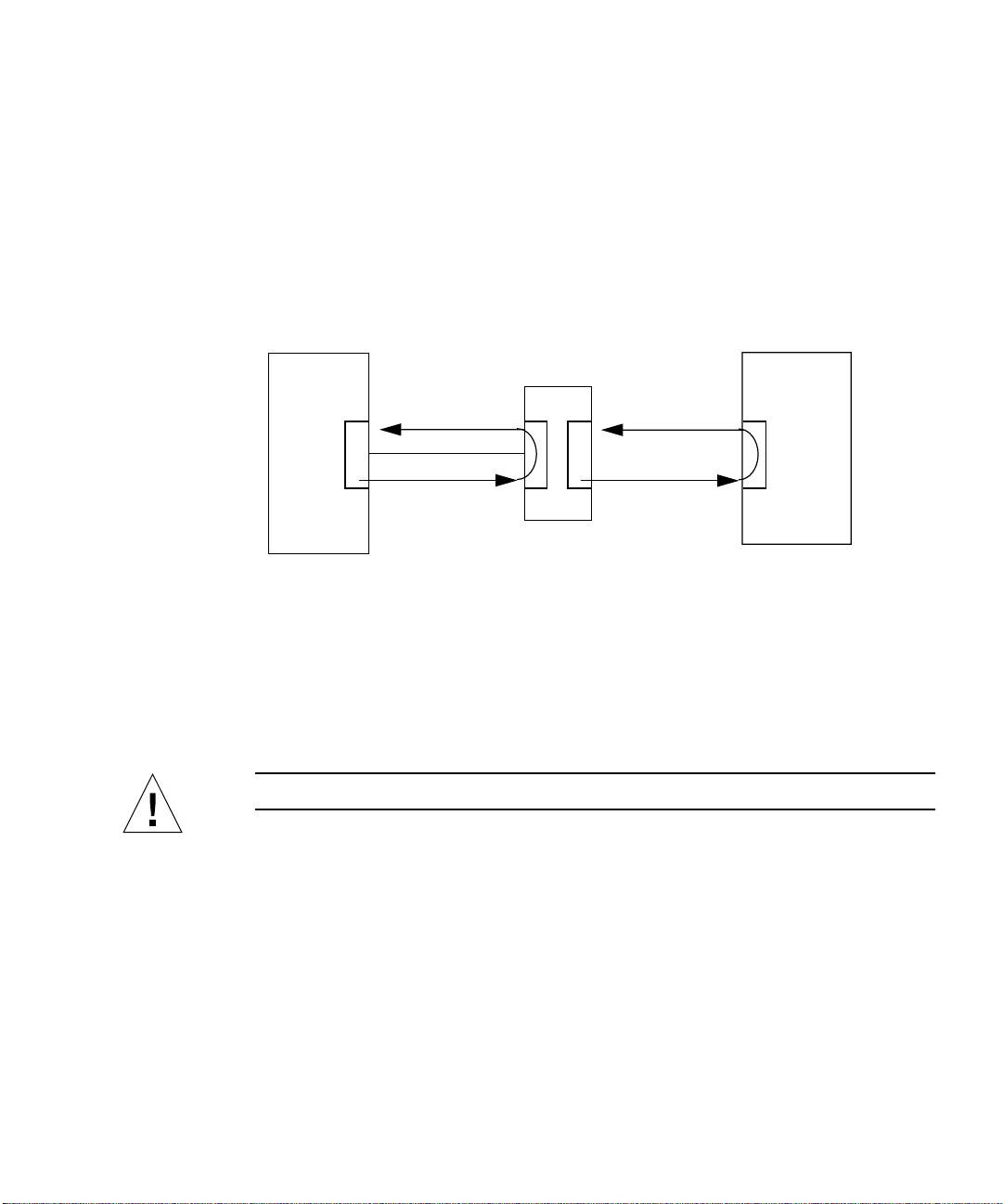
Sun StorEdge StorTools 4.x Array Tests (t3test, a5ktest, a3500fctest)
You can run Sun StorEdge StorTools 4.x Array Tests (t3test, a5ktest,
a3500fctest) to test the following portion of the Sun StorEdge Network FC
Switch-8 and Switch-16 configuration:
■ Entire path
This is online testing but may affect performance.
#1 #2
Host
FIGURE 21 Sun StorEdge StorTools 4.x Array Tests
If you cannot determine the problem path or component from the failure data you
gathered or from the tests, proceed with the following isolation.
■ To isolate further in offline testing, run Sun StorEdge StorTools 4.x Functional
Tests on one or more components in the path.
Switch
Storage
Caution – When running in online mode, deselect system board and HBA tests.
Sun StorEdge Network FC Switch-8 and Switch-16 Field Troubleshooting Guide—April, 2001 43
Page 56
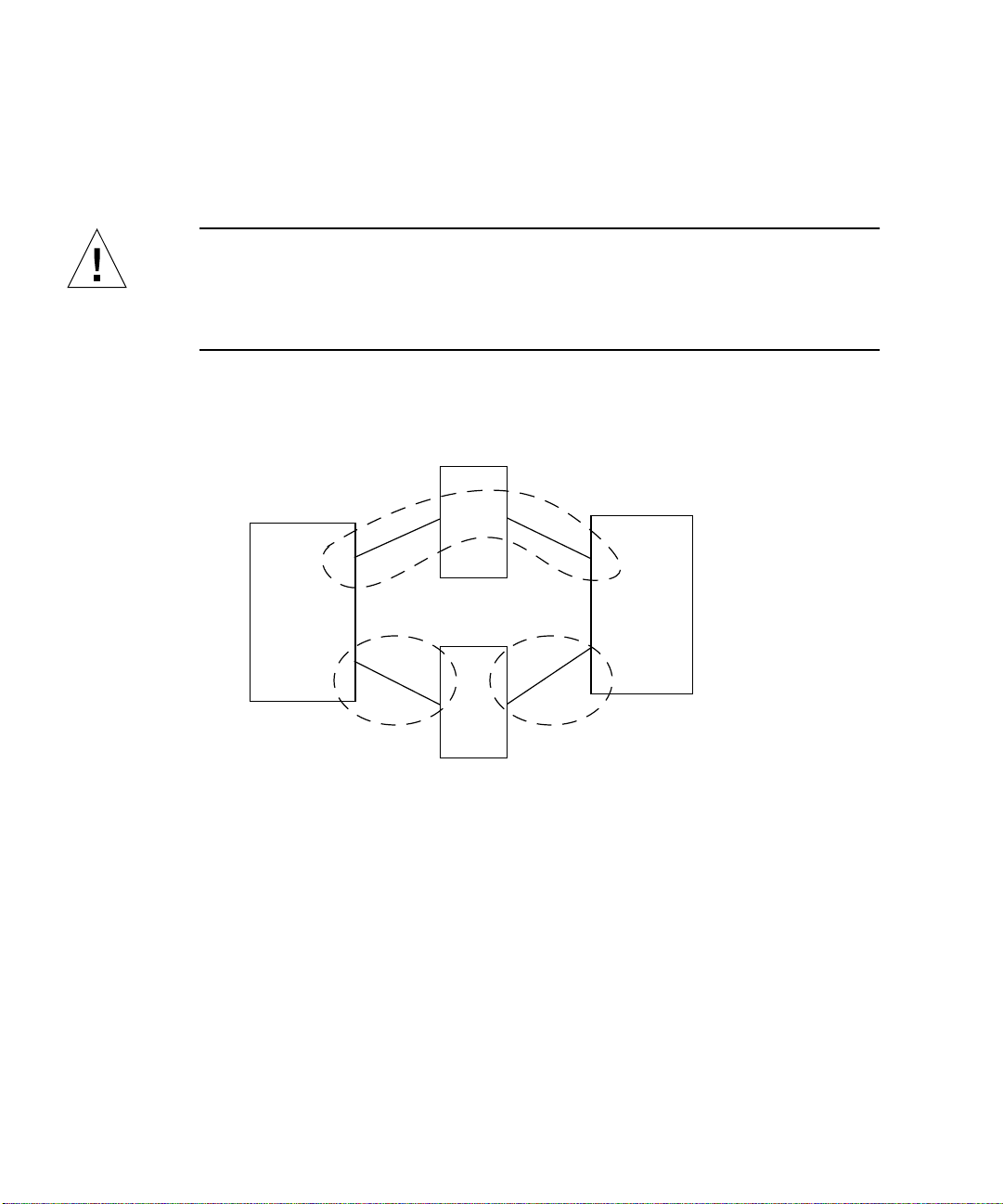
Diagnostic Isolation
Use the following diagram and accompanying information to help you with the
isolation process. See Appendix B, “Isolation of SAN Components.” This appendix
contains a generic flowchart, which describes how to isolate Mamba phase faults.
Caution – Be sure only the path under test is selected.
For more information about Sun StorEdge StorTools 4.x, refer to the Sun StorEdge
StorTools User’s Guide, Version 4.x, part number 806-6235-10.
Switch
Area 3
Host
Area 1
Switch
FIGURE 22 Isolation in Areas 1, 2, and 3
Storage
Area 2
44 Sun StorEdge Network FC Switch-8 and Switch-16 Field Troubleshooting Guide • April, 2001
Page 57

Area 1
If failure data indicate a problem in Area 1, execute Sun StorEdge StorTools 4.x and
one of the following tests:
■ switchtest for initiator port (online)
■ Appropriate HBA test
■ qlctest (offline)
■ soctest (offline)
These tests may indicate a failure and isolate to multiple FRUs (HBA, cable, switch
GBIC or switch).
For possible isolation to a single FRU, you can run CLI stexpert (offline).
Area 2
If failure data indicate a problem in Area 2, execute Sun StorEdge StorTools 4.x and
one of the following tests.
■ switchtest for destination port (online)
■ stexpert (offline) for possible isolation to a single FRU
These tests may indicate a failure and isolate to multiple FRUs (cable, switch GBIC,
or array).
Area 3
If failure data indicate a problem in Area 2 or Area 3, execute Sun StorEdge
StorTools 4.x and one of the following tests:
■ a5ksestest and/or a5ktest for A5k (both tests can be online)
■ t3test for T3 (online)
■ a3500fctest for A3500FC (online)
These tests apply to the storage and the entire path.
For possible isolation to a single FRU, you can run stexpert (offline).
Sun StorEdge Network FC Switch-8 and Switch-16 Field Troubleshooting Guide—April, 2001 45
Page 58

Examples of Fault Isolation
This section contains examples of failures and subsequent isolation techniques. In
general, the following items must be kept in mind before starting.
■ A Snapshot Create must be taken after the installation is complete. Than a
Snapshot Diff can be taken as part of the isolation process.
■ Sun StorEdge StorTools 4.x must be kept up and running to maintain the path
state. If a path fails it is not detected if Sun StorEdge StorTools 4.x is stopped.
Then the path cannot be tested until it has been fixed. Other tools are then
required for isolation ( /var/adm/messages, Switch GUI, etc.).
■ StorEdge Expert incurs long running times: up to twenty minutes per test and as
long as sixty minutes overall.
■ StorEdge Expert Tests are offline tests.
Options examples follow.
Scenario 1a—Bad Cable Between Host and Switch (Using StorEdge Expert)
In this example, the loss of two full A5200 arrays was seen in format and
/var/adm/messages. This can also be verified by doing a Snapshot diff in Sun
StorEdge StorTools 4.x and by using the SANSurfer GUI.
Note – Some output is abbreviated.
A functional test (a5ktest) was initially run on one of the A5200s to test the loop.
The StorEdge Expert was then used to isolate down to the IPORT_FIBER FRU.
Replacing the IPORT_FIBER fixed the condition.
46 Sun StorEdge Network FC Switch-8 and Switch-16 Field Troubleshooting Guide • April, 2001
Page 59

Functional a5ktest from Sun StorEdge StorTools 4.x GUI
02/08/01 15:54:12 diag233.Central.Sun.COM Sun VTS4.1: VTSID 1 a5ktest. VERBOSE
:”Options:
selftest=Enable,wrdevbuf=Enable,wrdevbufpasses=100,wrdevbufptn=Ox7e7e7e73,allwrd
evbufptn=Enable,partition=0,rawsub=Enable,method=SyncIO+AsyncIO,rawcover=1,raw
iosize=32KB,fssub=Disable,fssize-512KB,fsiosize=512B,fspattern=sequential,dev=
c2t32d0-f0)”
02/08/01 15:54:12 diag233.Central.Sun.COM Sun VTS4.1: VTSID 8014 a5ktest. FATAL
c2t32d0: “Couldn’t open /dev/rdsk/c2t32d0s0: No such device or address”
Probable_Causes(s):
(1) Cable loose or disconnected
(2) Device off-line or missing
(3) Device not configured
(4) Device bypassed
Recommended_Actions(s):
(1) Check cable
(2) Check device on-line
(3) Configure device
(4) Check A5k panel to see if drive is bypassed
Run StorEdge Expert on One Drive in Path
02/08/01 15:54:12 diag233.Central.Sun.COM Sun VTS4.1: VTSID 2100
a5ktest.expert.INFO c2t32d0: “Expert Started.”
02/08/01 15:54:12 diag233.Central.Sun.COM Sun VTS4.1: VTSID 6100
a5ktest.expert.
ERROR c2t32d0: “Expert error(s):reference Expert Log
<<Feb082001_15:58:23>> STARTED:diagnosis expert session on /dev/rdsk/c2t32d0s2
<<Feb082001_15:58:23>> FAILED: for details see:
/var/opt/SUNWvts/gogs/Feb082001_15:58:23_c2t32d0-f0.errlog
<<Feb082001_15:58:23>> NOTICE: todo manual Fault Isolation, type in
‘/opt/SUNWvts/bin/sparcv9/stexpert -i -t /dev/rdsk/c2t32d0s2’
<<Feb082001_16:20:04>> FAILED: for details see:
/var/opt/SUNWvts/logs/Feb082001_16:20:04_fc-8p-sw1-ip5[qlc-0].errlog
<<Feb082001_16:20:04>> NOTICE: IPORT_GBIC is a suspect component
<<Feb082001_16:20:04>> NOTICE: IPORT_FIBER is a suspect component
<Feb082001_16:20:04>> NOTICE: HBA is a suspect component
<Feb082001_16:20:04>> NOTICE: SWITCH is a suspect component
<Feb082001_16:20:04>> COMPLETED:diagnosis expert session on /dev/rdsk/c2t32d0s2
From the Command Line
/opt/SUNWvts/bin/sparv9/stexpert -i -t /dev/rdsk/c2t32d)s2
stexpert: Diagnosis Begins
<snip>
stexpert: Component replaced or Intermittent condition might exist
stexpert: Type ok to restart testing or exit to quit: quit
<<Feb082001_17:40:13>> NOTICE:IPORT_FIBER is a suspect component
<<Feb082001_17:40:13>> COMPLETED:diagnosis expert session on /dev/rdsk/c2t32d0s2
stexpert: Diagnosis Complete
Sun StorEdge Network FC Switch-8 and Switch-16 Field Troubleshooting Guide—April, 2001 47
Page 60
Scenario 2—Bad GBIC in Switch
In this example, the loss of a single A5200 loop was noted in format and
/var/adm/messages. Sun StorEdge StorTools 4.x Functional tests were used to
verify the loop quickly.The Sun StorEdge StorTools 4.x StorEdge Expert tests were
used to isolate down to a single failed GBIC on the switch. Replacing the GBIC fixed
the error condition.
/var/adm/messages
@0,0/ssd@w210000203719f810,0 (ssd107) offline
Feb 8 14:55:56 diag233.Central.Sun.COM genunix: [ID 408114 kern.info]
/pci@1f,4000/pci@4/SUNW,qlc@4/fp
@0,0/ssd@w21000002037450d71,0 (ssd120) offline
<snip>
Feb 8 14:55:56 diag233.Central.Sun.COM genunix: [ID 408114 kern.info]
/pci@1f,4000/pci@4/SUNW,qlc@4/fp
@0,0/ssd@w210000020373ccelc,0 (ssd109) offline
Run a5ktest from GUI
02/08/01 14:58:53 diag233.Central.Sun.COM Sun VTS4.1: VTSID 1 a5ktest. VERBOSE
:”Options:
selftest=Enable,wrdevbuf=Enable,wrdevbufpasses=100,wrdevbufptn=Ox7e7e7e73,allwrd
evbufptn=Enable,partition=0,rawsub=Enable,method=SyncIO+AsyncIO,rawcover=1,raw
iosize=32KB,fssub=Disable,fssize-512KB,fsiosize=512B,fspattern=sequential,dev=
c2t32d0-f0)
02/08/01 14:58:53 diag233.Central.Sun.COM Sun VTS4.1: VTSID 8014 a5ktest. FATAL
c2t0d0: “Couldn’t open /dev/rdsk/c2t0d0s0: No such device or address”
Probable_Causes(s):
(1) Cable loose or disconnected
(2) Device off-line or missing
(3) Device not configured
(4) Device bypassed
Recommended_Actions(s):
(1) Check cable
(2) Check device on-line
(3) Configure device
(4) Check A5k panel to see if drive is bypassed
48 Sun StorEdge Network FC Switch-8 and Switch-16 Field Troubleshooting Guide • April, 2001
Page 61
Run GUI StorEdge Expert on Same Disk
02/08/01 15:01:55 diag233.Central.Sun.COM Sun VTS4.1: VTSID 2100
a5ktest.expert.INFO c2t0d0: “Expert Started.”
02/08/01 15:01:56 diag233.Central.Sun.COM Sun VTS4.1: VTSID 6100
a5ktest.expert.
ERROR c2t02d0: “Expert error(s):reference Expert Log
<<Feb082001_15:01:55>> STARTED:diagnosis expert session on /dev/rdsk/c2t32d0s2
<<Feb082001_15:01:56>> FAILED: for details see:
/var/opt/SUNWvts/gogs/Feb082001_15:01:56_c2t0d0-f0.errlog
<<Feb082001_15:01:56>> NOTICE: to do manual Fault Isolation, type in
‘/opt/SUNWvts/bin/sparcv9/stexpert -i -t /dev/rdsk/c2t0d0s2’
<<Feb082001_15:01:56>> FAILED: for details see:
/var/opt/SUNWvts/logs/Feb082001_15:01:56_fc-8p-sw1-dp8[qlc-0].errlog
<<Feb082001_15:01:57>> NOTICE: DISK is a suspect component
<<Feb082001_15:01:57>> NOTICE: DPORT_GBIC is a suspect component
<<Feb082001_15:01:57>> NOTICE: IPORT_FIBER is a suspect component
<Feb082001_15:01:57>> NOTICE: DEV_GBIC is a suspect component
<Feb082001_15:01:57>> NOTICE: SWITCH is a suspect component
<Feb082001_15:01:57>> COMPLETED:diagnosis expert session on /dev/rdsk/c2t0d0s2
Sun StorEdge Network FC Switch-8 and Switch-16 Field Troubleshooting Guide—April, 2001 49
Page 62

Run StorEdge Expert from Command Line
/opt/SUNWvts/bin/sparv9/stexpert -i -t /dev/rdsk/c2t0d)s2
stexpert: Diagnosis Begins
<snip>
stexpert: Remove fiber cable from DPORT GBIC in port 8
stexpert: Type ok to restart testing or exit to quit: ok
Waiting 20 seconds for loopback to initialize
<<Feb082001_15:05:19>> STARTED: fc-8p-sw1-dp8[qlc-01]
<<Feb082001_15:05:19>> NOTICE: Executing switch_dport [64 bit version]
<<Feb082001_15:05:19>> COMPLETED:fc-8p-sw1-dp8[qlc-01]
<<Feb082001_15:05:19>> FAILED: for details see:
/var/opt/SUNWvts/gogs/Feb082001_15:05:19_fc-8p-sw1-dp8[qlc-01].errlog
stexpert: Remove the GBIC in port 8
stexpert: Insert anew GBIC in port 8
stexpert: Type ok to continue or exit to quit: ok
stexpert: Insert a loopback cable in DPORT GBIC in port 8
stexpert: Type ok to continue or exit to quit:ok
Waiting 20 seconds for loopback to initialize.
<<Feb082001_15:07:18>> STARTED: fc-8p-sw1-dp8[qlc-01]
<<Feb082001_15:07:18>> NOTICE: Executing switch_dport [64 bit version]
stexpert: Remove loopback cable connected to DPORT GBIC in port 8
stexpert: Type ok to continue or exit to quit: ok
stexpert: Install original DPORT fiber cable into DPORT GBIC port 8
stexpert: Type ok to continue or exit to quit: ok
stexpert: Component replaced or Intermittent condition might exist
GBIC WAS REPLACED!
stexpert: Type ok to restart testing or exit to quit:ok
<<Feb082001_15:31:40>> STARTED: c2t0d0-f0
<<Feb082001_15:31:40>> NOTICE: Executing SCSIBIT stress_test
ONLY IF YOU WANT TO STRESS TEST!
<<Feb082001_15:33:21>> NOTICE:Completed SCSIBIT stress_test
<<Feb082001_15:33:21>> NOTICE:Executing DEX stress_test
<<Feb082001_15:36:34>> NOTICE:Completed DEX stress_test
<<Feb082001_15:36:34>> STARTED: fc-8p-sw1-dp8[qlc-01]
<<Feb082001_15:36:34>> NOTICE: Executing switch_dport [64 bit version]
The disks have reappeared in format.
50 Sun StorEdge Network FC Switch-8 and Switch-16 Field Troubleshooting Guide • April, 2001
Page 63
Scenario 1b—Bad Cable Between Host and Switch (Using Functional Test)
In this example, the loss of all storage connected to a switch was noted in
/var/adm/messages and format (all disks labeled c2* were missing). A Snapshot
diff was run to determine the extent of the problem. Functional tests were used to
isolate individual subsection of the SAN to identify likely failed FRUs.
#format
Searching for disks. . .done
AVAILABLE DISK SELECTIONS:
0. c0t0d0 <SUN18G cyl 7506 alt 2 hd 19 sec 248>
/pci@1f,4000/scsi@3/sd@0,0
1. c0t8d0 <SUN18G cyl 7506 alt 2 hd 19 sec 248>
/pci@1f,4000/scsi@3/sd@8,0
2. c2t1d0 <drive type unknown>
/pci@1f,4000/pci@4/SUNW,qlc@4/fp@0,0/ssd@w210000203719f810,0
3. c2t2d0 <drive not available:formatting>
/pci@1f,4000/pci@4/SUNW,qlc@4/fp@0,0/ssd@w210000203719f803,0
4. c2t3d0 <drive not available:formatting>
/pci@1f,4000/pci@4/SUNW,qlc@4/fp@0,0/ssd@w210000203719f7d0,0
5. c2t4d0 <drive not available:formatting>
/pci@1f,4000/pci@4/SUNW,qlc@4/fp@0,0/ssd@w210000203719f6f4,0
6. c2t5d0 <drive not available:formatting>
/pci@1f,4000/pci@4/SUNW,qlc@4/fp@0,0/ssd@w210000203719eb58,0
7. c2t6d0 <drive not available:formatting>
/pci@1f,4000/pci@4/SUNW,qlc@4/fp@0,0/ssd@w210000203719f7b0,0
8. c2t8d0 <drive not available:formatting>
/pci@1f,4000/pci@4/SUNW,qlc@4/fp@0,0/ssd@w210000203745060f,0
9. c2t9d0 <drive not available:formatting>
/pci@1f,4000/pci@4/SUNW,qlc@4/fp@0,0/ssd@w210000203745d60b,0
10. c2t16d0 <drive not available:formatting>
/pci@1f,4000/pci@4/SUNW,qlc@4/fp@0,0/ssd@w21000020373ccelc,0
- hit space for more or s to select -
Snapshot Diff Results
Timestamp: Fri Feb 9 13:04:48 2001
Detected missing Host Bus Adapter Card.
Sun StorEdge Network FC Switch-8 and Switch-16 Field Troubleshooting Guide—April, 2001 51
Page 64

Either the card was removed or we can no longer see storage attached to this card.
Registername = qlc-0
LGroup = StorEdge-QLC-HostBusadapters
Pgroup = /StorEdge
Node WWN = 200000e08b026c2a
Port WWN = 20000e08b026c2a
DriverName = fp
Detected missing device:
Switch
Switch ip address = 172.20.67.194
Switch port number = 5
Register Name = fc-8p-sw1-ip5(qlc-0)
Logical Group = StorEdge-8p-Switches(qlc-0)
Physical Group =/StorEdge/qlc-0
Node WWN =200000e08b026c2a
Port WWN =210000e08b026c2a
Detected missing device:
Switch
Switch ip address = 172.20.67.194
Switch port number = 7
Register Name = fc-8p-sw1-ip7(qlc-0)
Logical Group = StorEdge-8p-Switches(qlc-0)
Physical Group =/StorEdge/qlc-0
Node WWN =200000e08b026c2a
Port WWN =210000e08b026c2a
Detected missing device:
Switch
Switch ip address = 172.20.67.194
Switch port number = 8
Register Name = fc-8p-sw1-ip5(qlc-0)
Logical Group = StorEdge-8p-Switches(qlc-0)
Physical Group =/StorEdge/qlc-0
Node WWN =200000e08b026c2a
Port WWN =210000e08b026c2a
Detected missing device:
A5x000 Enclosure
Box Name =
LogicalPath =/dev/es/ses9
PhysPath =
/devices/pci@1f,4000/pci@4/SUNW,qlc@4/fp@0,0/ses@w5080020000083cb1,0:0
Register Name =a5k-ses9
Logical Group =StorEdge-A5200-(qlc-0)
Physical Group =/StorEdge/qlc-0/fc-8p-sw1-ip5(qlc-0)/fc-8p-sw1-dp8(qlc-
0)/(qlc-0)
NodeWWN =5080020000083cb0
PortWWN =5080020000083cb1
...
(continued next page)
52 Sun StorEdge Network FC Switch-8 and Switch-16 Field Troubleshooting Guide • April, 2001
Page 65
...
Detected Missing device:
A5x00 Drive
Box Name =
Logical Path -/dev/rdsk/c2t0d0s2
PhysPath =
/devices/pci@1f,4000/pci@4/SUNW,qlc@4/fp@0,0/ssd@w210000203719f7e0,0:c,raw
Register Name =c2r0d0-f0
Logical Group =StorEdge-A5200-(qlc-0)
Physical Group =/StorEdge/qlc-0/fc-8p-sw1-ip5(qlc-0)/fc-8p-sw1-dp8(qlc-
0)/qlc-0)
NodeWWN =200000203719f7e0
PortWWN =210000203719f7e0
<snip>
Sun StorEdge Network FC Switch-8 and Switch-16 Field Troubleshooting Guide—April, 2001 53
Page 66
A Quick Functional Test (a5ksestest) to Test Full Loop
02/09/01 13:05:46 diag233,Central.Sun.COM SunVTS4.1:VTSID 1012
a5ksestest,process_photest_argsVERBOSE SES:nws_enatest: called with options:
disk_access=enable,delay=30,dev=a5k-ses11”
02/09/01 13:05:46 diag233,Central.Sun.COM SunVTS4.1:VTSID 0
a5ksestest.VERBOSE: “Started.”
02/09/01 13:05:46 diag233,Central.Sun.COM SunVTS4.1:VTSID 1000
a5ksestest.VERBOSE: “Started test on /dev/es/ses11”
02/09/01 13:05:46 diag233,Central.Sun.COM SunVTS4.1:VTSID 8005a5ksestest.
FATAL:”Could not communicate with the enclosure”
Probable_Cause(s):
(1) Faulty connection
Recommended_Action(s):
(1) Ensure the cables are properly connected
(2) Check GBICs if GBICs are present
(3) Run SunVTS host bus adapter tests
(4) Please contact your service representative
To further isolate, two passes of the switch test were run: one pass on the port
connected to the storage, fc-80-sw1-dp7(qlc-0), which isolates the switch-to-storage
path, and one pass on the port connected to the host, fc-80-sw1-ip5(qlc-0), to isolate
the host-switch path.
02/09/01 13:08:59 diag233,Central.Sun.COM SunVTS4.1:VTSID 0
switchtest.VERBOSE switch0: “Started.”
02/09/01 13:08:59 diag233,Central.Sun.COM SunVTS4.1:VTSID 7
switchtest.mmain.VERBOSE switch0: “Testing device fc-80-sw1-dp7(qlc-0).”
<snip>
02/09/01 13:09:49 diag233,Central.Sun.COM SunVTS4.1:VTSID 6033 switchtest.
FATAL switch0: “Switch not Connected on Port: 5 Pattern: 0x7e7e7e7e.”
Probable_Cause(s):
(1) Fibre Channel cable disconnected
(2) Bad GBIC or bad Fibre Channel cable
(3) Loss of power to switch
The switch-storage link passed, but the host-switch link failed. This indicates that
the failure is limited to the host-switch connection. The next step is to isolate the
FRUs in this path. A loopback connector is placed in the switch’s GBIC on port 5, fc8p-sw1-ip5(qlc-0) and switchtest on that port is rerun.
02/09/01 13:08:59 diag233,Central.Sun.COM SunVTS4.1:VTSID 6
switchtest.process_args.VERBOSE switch0: “switchtest: called with options:
xfer=2000,passes=100000,pattern=0x7e7e7e7e,allpaterns=Disable,wait=2,dev=fc-8p-sw1ip5(qlc-0)”
<snip>
02/09/01 13:17:58 diag233,Central.Sun.COM SunVTS4.1:VTSID 0 switchtest.VERBOSE
switch0: “Stopped successfully.”
This test passing tells us that the GBIC in the switch is functioning.
54 Sun StorEdge Network FC Switch-8 and Switch-16 Field Troubleshooting Guide • April, 2001
Page 67
A qlctest on the HBA in the path (qlc-0 in this example) can then be run to verify
the HBA. (For this test, all Test Parameter Options for qlctest were disabled, except
Online SelfTest and Firmware Checksum Test in the interest of test execution time.
Further testing could be done, but the execution time would increase.)
02/09/01 13:38:59 diag233,Central.Sun.COM SunVTS4.1:VTSID
6qlctest.process_qlctest_args.VERBOSE qlc: “qlctest: called with options:
run_connect=No,selftest=Enable,mbox=Disable,checksum=Enable,ilb_10-Disable,ilb=
Disable,elb=Disable,xcnt=)x2000,icnt=1,lbfpattern=0x7e7e7e7e,run_all=Disable,dev=
qlc-0”
<snip>
02/09/01 13:39:57 diag233,Central.Sun.COM SunVTS4.1:VTSID 0 qlctest.VERBOSE
/devices/pci@1f,4000/pci@4/SUNW,qlc@4/fp@0,0:devctl: “Stopped successfully.”
HBA can most likely be ruled out as the faulty component. All that is left is the hostto-switch cable. In this example, the cable was replaced. Watching the
/var/adm/messages revealed that the disks were rediscovered. A format check
revealed that the c2* disks were back.
Searching for disks...done
AVAILABLE DISK SELECTIONS
0. c0t0d0 <SUN18G cyl 7506 alt 2 hd 19 sec 248>
/pci@1f,4000/scsi@3/sd@0,0
1. c0t8d0 <SUN18G cyl 7506 alt 2 hd 19 sec 248>
/pci@1f,4000/scsi@3/sd@8,0
2. c2t0d0 <SUN9.0G cyl 4924 alt 2 hd 27 sec 133>
/pci@1f,4000/pci@4/SUNW,qlc@4/fp@0,0/ssd@w210000203719f7e0,0
3. c2t1d0 <SUN9.0G cyl 4924 alt 2 hd 27 sec 133>
/pci@1f,4000/pci@4/SUNW,qlc@4/fp@0,0/ssd@w210000203719f810,0
4. c2t2d0 <SUN9.0G cyl 4924 alt 2 hd 27 sec 133>
/pci@1f,4000/pci@4/SUNW,qlc@4/fp@0,0/ssd@w210000203719f803,0
5. c2t3d0 <SUN9.0G cyl 4924 alt 2 hd 27 sec 133>
/pci@1f,4000/pci@4/SUNW,qlc@4/fp@0,0/ssd@w210000203719f7d0,0
6. c2t5d0 <SUN9.0G cyl 4924 alt 2 hd 27 sec 133>
/pci@1f,4000/pci@4/SUNW,qlc@4/fp@0,0/ssd@w210000203719f6f4,0
7. c2t6d0 <SUN9.0G cyl 4924 alt 2 hd 27 sec 133>
/pci@1f,4000/pci@4/SUNW,qlc@4/fp@0,0/ssd@w210000203719eb58,0
8. c2t8d0 <SUN9.0G cyl 4924 alt 2 hd 27 sec 133>
/pci@1f,4000/pci@4/SUNW,qlc@4/fp@0,0/ssd@w210000203719f7b0,0
9. c2t9d0 <SUN9.0G cyl 4924 alt 2 hd 27 sec 133>
/pci@1f,4000/pci@4/SUNW,qlc@4/fp@0,0/ssd@w210000203719f802,0
10. c2t16d0 <SUN9.0G cyl 4924 alt 2 hd 27 sec 133>
/pci@1f,4000/pci@4/SUNW,qlc@4/fp@0,0/ssd@w210000203745060f,0
11. c2t9d0 <SUN9.0G cyl 4924 alt 2 hd 27 sec 133>
Sun StorEdge Network FC Switch-8 and Switch-16 Field Troubleshooting Guide—April, 2001 55
Page 68
Another a5ksestest to Verify the Full Path—Successful
02/09/01 13:44:16 diag233.Central.Sun.COM SunVTS4.1: VTSID 1012
a5ksestest.process_photest_argsVERBOSE SES: “nws_enatest: called with options:
disk_access=enable,delay=30,dev=a5k-ses11”
02/09/01 13:44:16 diag233.Central.Sun.COM SunVTS4.1: VTSID 0
a5ksestest.VERBOSE: “Started.”
<snip>
02/09/01 13:44:59 diag233.Central.sun.COM SunVTS: VTSID0 a5ksestest.VERBOSE:
“Stopped successfully.”
Scenario 3—Catastrophic Switch Failure
In this example, an entire switch has gone offline. Even though this example shows
Sun StorEdge StorTools 4.x being used to identify the failure, other methods, such as
visual inspection of the switch and checking the switch GUI, would lead to the same
conclusion. The scenario was first seen when all storage connected to this switch
disappeared from format. A Snapshot Diff was first run to verify the extent of the
failure.
Detected missing device:
Switch
Switch ip address = 172.20.67.194
Switch port number = 1
Register Name = fc-8p-sw1-ip1(qlc-1)
Logical Group = StorEdge-8p-Switches(qlc-1)
Physical Group =/StorEdge/qlc-1
Node WWN =200000e08b026c2a
Port WWN =210000e08b026c2a
Detected missing device:
Switch
Switch ip address = 172.20.67.194
Switch port number = 3
Register Name = fc-8p-sw1-dp3(qlc-1)
Logical Group = StorEdge-8p-Switches(qlc-1)
Physical Group =/StorEdge/qlc-1/fc-8p-sw1-ip1(qlc-1)
Node WWN =200000e08b026c2a
Port WWN =210000e08b026c2a
Detected missing device:
A5x000 Enclosure
Box Name =
LogicalPath =/dev/es/ses9
PhysPath =
/devices/pci@1f,4000/pci@4/SUNW,qlc@4/fp@0,0/ses@w5080020000083cb1,0:0
Register Name =a5k-ses9
Logical Group =StorEdge-A5200-(qlc-0)
Physical Group =/StorEdge/qlc-0/fc-8p-sw1-ip5(qlc-0)/fc-8p-sw1-dp8(qlc-
0)/(qlc-0)
NodeWWN =5080020000083cb0
PortWWN =5080020000083cb1
56 Sun StorEdge Network FC Switch-8 and Switch-16 Field Troubleshooting Guide • April, 2001
Page 69
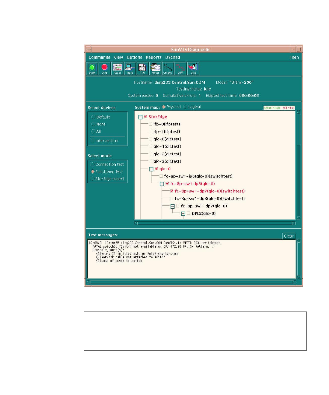
Functional Test of Switch (switchtest)
FIGURE 23 Functional Test of Switch window
02/09/01 10:19:55 diag233.Central.Sun.COM SunVTS4.1: VTSID 6031 switchtest
FATAL switch0: “Switch not available on IP: 172.20.67.194 Pattern:.”
Probable_Cause(s):
(1) Wrong IP in /etc/hosts or /etc/fcswitch.conf
(2) Network cable not attached to switch
(3) Loss of power to switch
Sun StorEdge Network FC Switch-8 and Switch-16 Field Troubleshooting Guide—April, 2001 57
Page 70
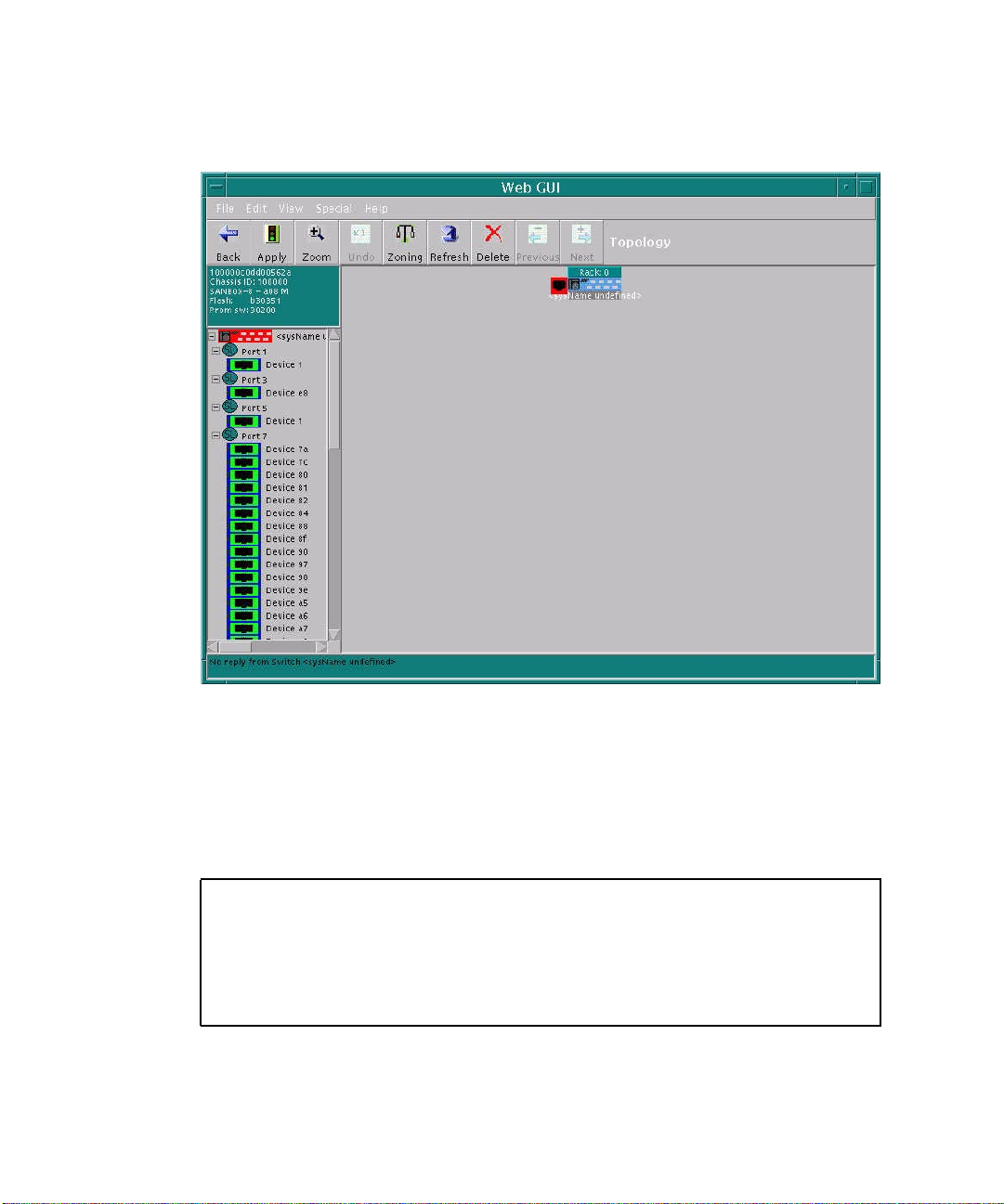
Look to Switch GUI
No response from switch GUI, no connection.
FIGURE 24 Switch GUI window
Check Weblog.gui (/usr/opt/SUNWsmgr/Weblog.gui)
A visual inspection of the switch revealed it was inadvertenly powered down, so the
switch was repowered.
02/09/2001 10:23:47 <sysName undefined> timeout - No replay from Switch
02/09/2001 10:23:47 <sysName undefined> timeout - No replay from Switch
02/09/2001 10:23:47 <sysName undefined> timeout - No replay from Switch
02/09/2001 10:23:47 <sysName undefined> timeout - No replay from Switch
02/09/2001 10:23:47 <sysName undefined> timeout - No replay from Switch
02/09/2001 10:23:47 <sysName undefined> timeout - No replay from Switch
02/09/2001 10:23:47 <sysName undefined> timeout - No replay from Switch
02/09/2001 10:23:47 <sysName undefined> timeout - No replay from Switch
58 Sun StorEdge Network FC Switch-8 and Switch-16 Field Troubleshooting Guide • April, 2001
Page 71
Scenario 4—Bad Cable from Switch to Storage
In this example, the loss of one path to an A5200 array was noted in format. A
Snapshot Diff was run to determine the extent of the failure. Sun StorEdge StorTools
4.x Functional Tests were used to isolate various subsections of the SAN.
Snapshot Diff shows loss of entire Sun StorEdge A5200 enclosure.
Detected missing device:
Switch
Switch ip address = 172.20.67.194
Switch port number = 7
Register Name = fc-8p-sw1-ip7(qlc-0)
Logical Group = StorEdge-8p-Switches(qlc-0)
Physical Group =/StorEdge/qlc-0
Node WWN =200000e08b026c2a
Port WWN =210000e08b026c2a
Detected Missing device:
A5x00 Enclosure
Box Name =DPL2
Logical Path =/dev/es/ses11
PhysPath =
/devices/pci@1f,4000/pci@4/SUNW,qlc@4/fp@0,0/ses@w508002000007ca19,0:0
Register Name =a5k-ses11
Logical Group =StorEdge-A5200-DPL2(qlc-0)
Physical Group =/StorEdge/qlc-0/fc-8p-sw1-ip5(qlc-0)/fc-8p-sw1-dp7(qlc-
0)/DPL2qlc-0)
NodeWWN =508002000007ca18
PortWWN =508002000007ca19
Run Functional Test (a5ksestest) against the Failed Enclosure
02/09/01 09:28:18 diag 233.Central.Sun.COM SunVTS4.1: VTSID 1012
a5ksestest.process_photest_args. VERBOSE SES: “nws_enatest: called with options:
disk_access=enable,delay=30,dev=a5k-ses11”
02/09/01 0l:28:18 diag 233.Central.Sun.COM SunVTS4.1: VTSID 0
a5ksestest.VERBOSE: “Started.”
02/09/01 0l:28:18 diag 233.Central.Sun.COM SunVTS4.1: VTSID 1000
a5ksestest.VERBOSE: “Started test on /dev/es/ses11”
02/09/01 0l:28:18 diag 233.Central.Sun.COM SunVTS4.1: VTSID 8005 a5ksestest.
FATAL: “Could not communicate with the enclosure”
Probable_Causes(s):
(1) Faulty connection
Recommended_Action(s)
(1) Ensure the cables are properly connected
(2) Check GBICs if GBICs are present
Sun StorEdge Network FC Switch-8 and Switch-16 Field Troubleshooting Guide—April, 2001 59
Page 72
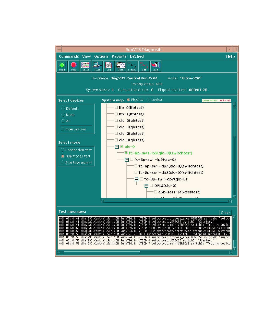
Run Functional Test (switchtest) on the Initiator Port to Test Host-Switch Link
FIGURE 25 Functional Test (switchtest) on Initiator Port to Test Host-Switch Link
60 Sun StorEdge Network FC Switch-8 and Switch-16 Field Troubleshooting Guide • April, 2001
window
Page 73
02/09/01 09:31:23 diag 233.Central.Sun.COM SunVTS4.1: VTSID 0
switchtest.VERBOSE switch0: “Started.”
<snip>
02/09/01 09:31:59 diag 233.Central.Sun.COM SunVTS4.1: VTSID 0
switchtest.VERBOSE switch0: “Stopped successfully.”
Sun StorEdge Network FC Switch-8 and Switch-16 Field Troubleshooting Guide—April, 2001 61
Page 74
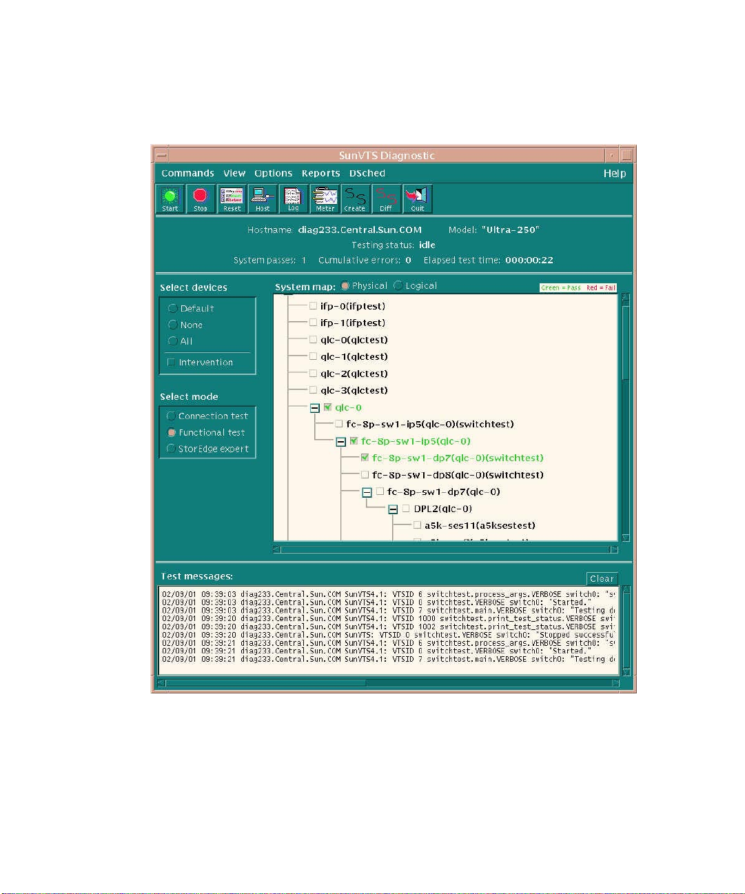
Run Functional Test (switchtest on the Destination Port to Test Switch-Storage Link
FIGURE 26 Functional Test (switchtest) on Destination Port to Test Switch-Storage Link
62 Sun StorEdge Network FC Switch-8 and Switch-16 Field Troubleshooting Guide • April, 2001
window
Page 75
02/09/01 09:35:16 diag233.Central.Sun.COM Sun VTS4.1: VTSID 6
switchtest.process_args.VERBOSE switch0: “switchtest: called with options: xfer=
2000,passes=100000,pattern=0x7e7e7e7e,allpatterns=Disable,wait=2,dev=fc-8p-sw1dp7(qlc-0)”
02/09/01 09:35:16 diag233.Central.Sun.COM Sun VTS4.1: VTSID 0
switchtest.VERBOSE switch0: “Started.”
<snip>
FATAL switch0: “Switch not Connected on Port: 7 Pattern: 0x7e7e7e7e.”
Probable_Cause(s):
(1) Fibre Channel cable disconnected
(2) Bad GBIC or bad Fibre Channel cable
(3) Loss of power to switch
Sun StorEdge Network FC Switch-8 and Switch-16 Field Troubleshooting Guide—April, 2001 63
Page 76
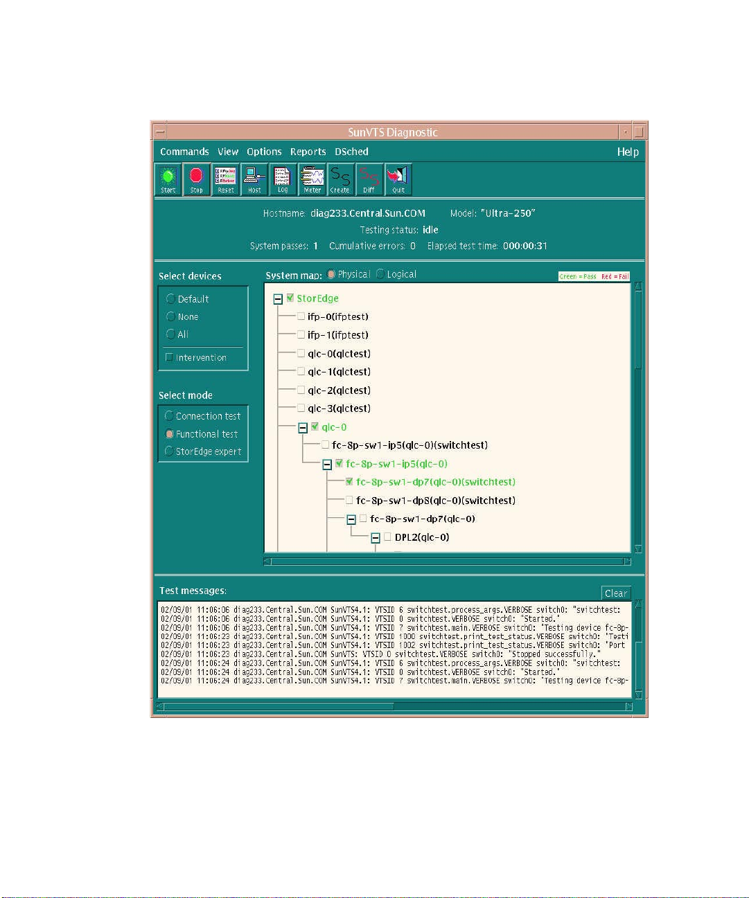
Insert Loopback in Destination Port to Test Switch’s GBIC
FIGURE 27 Insert Loopback in Destination Port to Test Switch’s GBIC window
64 Sun StorEdge Network FC Switch-8 and Switch-16 Field Troubleshooting Guide • April, 2001
Page 77
02/09/01 09:39:03 diag233.Central.Sun.COM Sun VTS4.1: VTSID 6
switchtest.process_args.VERBOSE switch0: “switchtest: called with options: xfer=
2000,passes=100000,pattern=0x7e7e7e7e,allpatterns=Disable,wait=2,dev=fc-8p-sw1dp7(qlc-0)”
02/09/01 09:39:03 diag233.Central.Sun.COM Sun VTS4.1: VTSID 0
switchtest.VERBOSE switch0: “Started.”
<snip>
02/09/01 09:39:03 diag233.Central.Sun.COM Sun VTS4.1: VTSID 0
switchtest.VERBOSE switch0: “Stopped successfully.”
Problem is isolated to switch-to-storage cable or GBIC/connector on storage side. If
the switch has empty ports, the storage-side GBIC could be temporarily placed in
switch for loopback testing. This would help to eliminate needless swapping of
parts.
Sun StorEdge Network FC Switch-8 and Switch-16 Field Troubleshooting Guide—April, 2001 65
Page 78
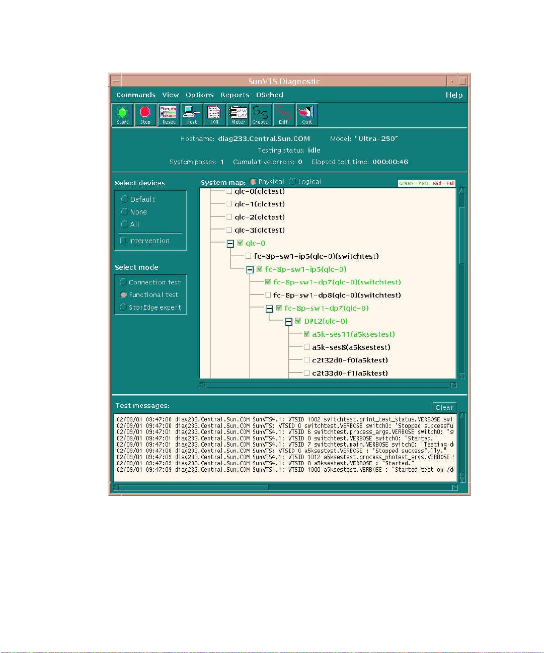
In this instance, the cable was bad, and the replaced cable reran a5ksestest.
FIGURE 28 Rerun a5ksesTest window
66 Sun StorEdge Network FC Switch-8 and Switch-16 Field Troubleshooting Guide • April, 2001
Page 79
Scenario 5—Bad GBIC in Storage (A5200)
In this example, the loss of an A5200 loop was noted in /var/adm/messages and
format. A Snapshot Diff was run to determine the extent of the failure. A Sun
StorEdge StorTools 4.x Functional Test was run to do a quick loop test. StorEdge
Expert was used to isolate down to a minimal number of suspect FRUs.
/var/adm/messages
Feb 8 10:08:53 diag233.Central.Sun.COM qlc: [ID 686697 kern.info] NOTICE: Qlogic
qlc(0): Loop OFFLINE
Feb 8 10:09:10 diag233.Central.Sun.COM qlc: [ID 686697 kern.info] NOTICE: Qlogic
qlc(0): Loop ONLINE
Feb 8 10:09:10 diag233.Central.Sun.COM qlc: [ID 999315 kern.info] WARNING: fctl(0):
AL_PA=0x7c doesn’t exist in LILP map
Feb 8 10:09:10 diag233.Central.Sun.COM qlc: [ID 999315 kern.info] WARNING: fctl(0):
AL_PA=0xac doesn’t exist in LILP map
Feb 8 10:09:10 diag233.Central.Sun.COM qlc: [ID 999315 kern.info] WARNING: fctl(0):
AL_PA=0xad doesn’t exist in LILP map
Feb 8 10:09:10 diag233.Central.Sun.COM qlc: [ID 999315 kern.info] WARNING: fctl(0):
AL_PA=0xa6 doesn’t exist in LILP map
Feb 8 10:09:10 diag233.Central.Sun.COM qlc: [ID 999315 kern.info] WARNING: fctl(0):
AL_PA=0x90 doesn’t exist in LILP map
<snip>
Feb 8 10:09:10 diag233.Central.Sun.COMofflining lun=0 target=7c
Feb 8 10:09:10 diag233.Central.Sun.COMscsi: [ID 243001
kern.info]/pci@1f,4000/pci@4/SUNW,qlc@4/fp@0,0 (fcp0)
Feb 8 10:09:10 diag233.Central.Sun.COMofflining lun=0 target=ac
Feb 8 10:09:10 diag233.Central.Sun.COMscsi: [ID 243001
kern.info]/pci@1f,4000/pci@4/SUNW,qlc@4/fp@0,0 (fcp0)
Sun StorEdge Network FC Switch-8 and Switch-16 Field Troubleshooting Guide—April, 2001 67
Page 80
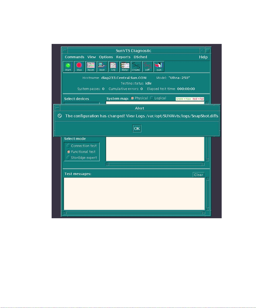
Run Snapshot DIFF
FIGURE 29 Run Snapshot DIFF window
68 Sun StorEdge Network FC Switch-8 and Switch-16 Field Troubleshooting Guide • April, 2001
Page 81
Timestamp: Thu Feb 8 10:19:40 2001
Detected missing Host Bus Adapter Card.
Either the card was removed or we can no longer see storage attached to this card.
Registername=qlc-0
LGroup =StorEdge-QLC-HostBus adapters
Pgroup =/StorEdge
Node WWN =2000000e08b026c2a
Port WWN =2100000e08b026c2a
Driver Name =fp
Detected Missing device:
A5x00 Enclosure
Box Name =DPL2
Logical Path =/dev/es/ses8
PhysPath =
/devices/pci@1f,4000/pci@4/SUNW,qlc@4/fp@0,0/ses@w508002000007ca1a,0:0
Register Name =a5k-ses8
Logical Group =StorEdge-A5200-DPL2(qlc-0)
Physical Group =/StorEdge/qlc-0/fc-8p-sw1-ip5(qlc-0)/fc-8p-sw1-dp7(qlc-
0)/DPL2qlc-0)
NodeWWN =508002000007ca18
PortWWN =508002000007ca1a
Detected Missing device:
A5x00 Drive
Box Name =DPL2
Logical Path -/dev/rdsk/c2t32d0s2
PhysPath =
/devices/pci@1f,4000/pci@4/SUNW,qlc@4/fp@0,0/ssd@w210000203733afbd0,0:c,raw
Register Name =c2t32d0-f0
Logical Group =StorEdge-A5200-DPL2(qlc-0)
Physical Group =/StorEdge/qlc-0/fc-8p-sw1-ip5(qlc-0)/fc-8p-sw1-dp8(qlc-
0)/DPL2qlc-0)
NodeWWN =200000203733af7bd
PortWWN =210000203733af7bd
Sun StorEdge Network FC Switch-8 and Switch-16 Field Troubleshooting Guide—April, 2001 69
Page 82
Run a5ktest on Drive in Failed Path
02/08/01 10:59:23 diag233.Central.Sun.COM SunVTS4.1:VTSID 8014 a5ktest.
FATAL c2t32d0: “Couldn’t open /dev/rdsk/c2t32d0s0: No such device or address”
Probable_Causes(s):
(1) Cable loose or disconnected
(2) Device off-line or missing
(3) Device not configured
(4) Device bypassed
Recommended_Actions(s):
(1) Check cable
(2) Check device on-line
(3) Configure device
(4) Check A5k panel to see if drive is bypassed
Run From Command Line
#/opt/SUNWvts/bin/sparcv9/stexpert-i-t /dev/rdsk/c2t32d0s2
stexpert: Diagnosis Begins
<snip>
<<Feb082001_13:50:52>FAILED: for details see:
/var/opt/SUNWvts/logs/Feb082001_13:50:52_fc-8p-sw1-dp7[qlc-0]errlog
stexpert: Remove fiber cable from DPORT GBIC in port 7
stexpert: Type ok to restart testing or exit to quit: ok
stexpert: Insert a loopback cable in DPORT GBIC in port 7
stexpert: Type ok to continue or exit to quit:ok
Waiting 20 seconds for loopback to initialize.
<<Feb082001_13:52:24>> STARTED: fc-8P-sw1-DP7[qlc-0)
<<Feb082001_13:52:24>> NOTICE: Executing switch_dport [64 bit version]
stexpert: Remove loopback cable connected to DPORT GBIC in port 7
stexpert: Type ok to continue or exit to quit: ok
stexpert: Install a new fiber cable between DPORT GBIC port 7 and device
/dev/rdsk/c2t32d0s2
stexpert: Type ok to continue or exit to quit: ok
Timed out waiting for loop to reinitialize
<<Feb082001_14:25:26>> NOTICE: DISK is a suspect component
<<Feb082001_14:25:26>> NOTICE: DPORT_FIBER is a suspect component
<<Feb082001_14:25:26>> NOTICE: DEV_GBIC is a suspect component
<<Feb082001_14:25:26>> COMPLETED: diagnosis expert session on /dev/rdsk/c2t32d0s2
stexpert: Diagnosis Complete
Errors detected - see /var/opt/SUNWvts/logs/activity.log
Testing on the other path to the Sun StorEdge A5200 array can help eliminate bad
disks. If possible, move the suspected storage GBIC to the switch and do loopback
testing. In this case, loopback testing revealed a bad GBIC.
70 Sun StorEdge Network FC Switch-8 and Switch-16 Field Troubleshooting Guide • April, 2001
Page 83
GBIC Replaced
/var/adm/messages
Feb 8 14:34:19 diag233.Central.Sun.COM qlc: [ID686697 kern.info] NOTICE: Qlogic
qlc(0): Loop ONLINE
Feb 8 14:34:19 diag233.Central.Sun.COM qlc: [ID799468 kern.info] ssd92 at fp0:name
w2100002037450d3a,0, bus address bc
Feb 8 14:34:19 diag233.Central.Sun.COM qlc: [ID936769 kern.info] ssd92 is
/pci@1f,4000/pci@4/SUNW,qlc@4/fp@0,0/ssd@w2100002037450d3a,0
<snip>
Verify with a GUI Functional Test (a5ktest)
<snip>
02/08/01 14:50:05 diag233.Central.Sun.COM SunVTS4.1:VTSID 50 a5ktest.VERBOSE
c2t32d0: “Self Test took 5 seconds to execute”
02/08/01 14:50:05 diag233.Central.Sun.COM SunVTS4.1:VTSID 34 a5ktest.VERBOSE
c2t32d0: “number of blocks 16019451”
02/08/01 14:50:05 diag233.Central.Sun.COM SunVTS4.1:VTSID 35 a5ktest.VERBOSE
c2t32d0: “Testing 160194 blocks on disk”
02/08/01 14:50:05 diag233.Central.Sun.COM SunVTS4.1:VTSID 24 a5ktest.VERBOSE
c2t32d0: “blk_base(),base=1,nblk=16019451”
02/08/01 14:50:05 diag233.Central.Sun.COM SunVTS4.1:VTSID 32 a5ktest.VERBOSE
c2t32d0: “Start AsyncIO test from block 1 to 160195.”
02/08/01 14:50:05 diag233.Central.Sun.COM SunVTS4.1:VTSID 36 a5ktest.VERBOSE
c2t32d0: “Start SyncIO test.”
02/08/01 14:50:05 diag233.Central.Sun.COM SunVTS4.1:VTSID 23 a5ktest.VERBOSE
c2t32d0: “Test passed.”
<snip>
At this point format revealed that the disks were back online.
Sun StorEdge Network FC Switch-8 and Switch-16 Field Troubleshooting Guide—April, 2001 71
Page 84

72 Sun StorEdge Network FC Switch-8 and Switch-16 Field Troubleshooting Guide • April, 2001
Page 85

APPENDIX
A
Mamba Field Troubleshooting Guide FAQ
Q Are 2x7 and 3x15 Sun StorEdge A3500-FC configurations supported in the
Mamba phase?
A Yes. 1x5, 2x7, and 3x15 Sun StorEdge A3500-FC configurations are supported in
the Mamba phase.
Q What is the difference between “SL Zoning” and “Hard Zoning?”
A In the Mamba phase, there is only the concept of an SL Zoning. SL Zones group
individual SL Ports into larger, logical loops. A port can be in one and only one
SL Zone at a time. Hard Zones will not be applicable until the Python release or
later.
The “big picture” answer, however, is that SL Zoning and Hard Zoning are both
based on a port-by-port basis and multiple SL Zones could live within a single
Hard Zone, but that is a topic for a later switch phase.
Q I’ve heard that the Qlogic switch GUI is embedded in the switch itself. Can the
Sun StorEdge switch be used that way? Can the GUI be used through a web
browser such as Netscape?
73
Page 86

A No. The current Sun switch GUI is installed with the SUNWsmgr package. The
current version of this GUI is 2.07.54 (or 2.07.50, with patch 110696-xx — this
patch can be found on Sunsolve). The syntax is as follows:
java -jar /usr/opt/SUNWsmgr/bin/Sun.jar
Refer to the installation guide for instructions on how to install the package.
The GUI is launched from a command line in a Java application. No other GUIs
are supported. This GUI can also be launched from within the Component
Manager 2.1 framework via a separate launch button.
Q Where can I get the latest patches and firmware for a Mamba configuration?
A The most current list of required patches, firmware, and other software packages
for Mamba can be found in the Sun StorEdge Network FC switch-8 and switch16 Release Notes, part number 806-6924-14, on page 2.
As is detailed in the Release Notes, you can download the switch firmware and
GUI from the Sun Network Storage Product Page at
http://www.sun.com/storage/san. You can find the required patches on
the Sunsolve website:
The maintainer of Early Notifier 14838 HES—CTE NWS SSA, A5x00/E3500 and
T3 Software/Firmware Config Matrix Summary is also said to be planning to
incorporate the required Mamba revisions in future versions of that document;
however, this has not yet been finalized.
Various internal NWS Engineering pages exist with various levels of patches and
firmware. Most of these pages are for various testing teams, and they may or
may not have the current GA-level software.
http://sunsolve.sun.com.
Q Is the switch firmware or GUI software from Qlogic’s website supported by Sun?
A No. The only supported switch firmware and GUI software are the Mamba
revisions from Sun.
Q Are there any configuration files that are needed if a switch is replaced?
74 Sun StorEdge Network FC Switch-8 and Switch-16 Field Troubleshooting Guide • April 2001
Page 87

A Yes. There is a file that should be saved, an Archive Fabric Config file. This file
holds an archived copy of chassis configurable parameters, such as port modes,
fabric name, SNMP settings, and zoning information (except zoning
descriptions).
After configuring the switch, create an archive file by clicking Special --> Archive
Fabric from the topology view in the switch GUI. Then, name the file whatever
you wish.
To replace a switch, load the file onto the new switch by clicking Special -->
Restore Fabric and choose the appropriate file. This will quickly reconfigure the
new switch.
Q How do I recover the switch if the administrator forgets the password?
A A package removal of SUNWsmgr (pkgrm SUNWsmgr), followed by a package
add (pkgadd SUNWsmgr) will restore the package. Once you have added the
package a second time using the pkgadd command, the login and password will
be back to the default values of su:su.
Q Are there any guidelines on using the switch GUI’s port counters for
troubleshooting?
A At this time, there are no set rules for troubleshooting using the port counters.
Efforts are underway to incorporate counter methodology into the serviceability
strategy for the Python phase.
However, there are several broad pointers:
1. Reset the counters before beginning any troubleshooting. A switch that has
counter information for the last six months would not necessarily give
meaningful information.
2. Pay particularly close attention to the following fields:
• Sync Loss 100ms
• Invalid tx words recv
• LIP total received
• Loss of Signal
• Sync Loss
Note:
LIPs will be seen by all SL ports in the same SL Zone. The other counters only
reflect conditions on the particular point being monitored.
Q What size screwdriver fits in the switch’s rotary Test Mode dial?
Appendix A Mamba Field Troubleshooting Guide FAQ 75
Page 88
A A Phillips-head screwdriver, size #0.
Q Sun StorEdge StorTools 4.x is indicating a problem related to qlc0. What physical
path is that?
A You can find the physical path by bringing up the Sun StorEdge StorTools 4.x
GUI, right clicking on qlc0 (qlctest) and selecting Test Parameter Options.
The physical path is indicated at the top of the screen.
Alternatively, you can pull this information from the /var/adm/messages or
the /etc/path_to_inst
Examples:
# grep -h "qlc0 is" /var/adm/messages | sort -M | tail -1
Mar 14 18:07:02 diag233.Central.Sun.COM genunix: [ID 936769 kern.info] qlc0 is
/pci@1f,4000/pci@4/SUNW,qlc@4
# grep \"qlc\" /etc/path_to_inst | grep " 0 "
"/pci@1f,4000/pci@4/SUNW,qlc@4" 0 "qlc"
Q StorTools 3.x was previously used to track patches and firmware revisions. What
do I use now?
A Sun StorEdge RASAgent 1.1 has taken the revision checking functionality from
Sun StorEdge StorTools 4.x. Sun StorEdge RASAgent 1.1 still uses the same Early
Notifier Doc 14838 HES—CTE NWS SSA, A5x00/E3500 and T3
Software/Firmware Config Matrix Summary that Sun StorEdge StorTools used.
Sun StorEdge RASAgent 1.1 also provides online monitoring and can be
configured to send an administrator email on certain events.
See the Sun StorEdge RASAgent 1.1 download page at
http://nscc.central/CC/RASAgent/release.pl?version=11 for
access to the RASAgent 1.1 manuals.
76 Sun StorEdge Network FC Switch-8 and Switch-16 Field Troubleshooting Guide • April 2001
Page 89
An example email of a Sun StorEdge RASAgent 1.1 Sun StorEdge T3 array LUN failover email
is shown below.
You requested the following events be forwarded to you.
1 Message-Log Warnings:
** Identification: T300 - purple7 **
key=50020F23000003C5, ip=purple7, key_type=wwn,
hostid=80b20f57, date=2001-03-17 16:00:18
** New Information **
Warning : component='u2ctr', date='2001-03-17 15:54:10', name='purple7',
text='u2ctr starting lun 0 failover',
Warning : component='u2ctr', date='2001-03-17 15:54:16', name='purple7',
text='u2ctr starting lun 0 failover',
Note – Customers’ adoption of RASAgent is critical in order to make it a useful tool for Field
Engineers. RASAgent will be of little use to Field Engineers if it is not installed with the
remainder of the Mamba components and is not running before problems begin. Marketing
efforts are underway to speed up customers’ adoption of the Sun StorEdge RASAgent 1.1.
Q How can I find out what PCI Fibre Channel Adapters are installed on a system?
A You can find out what Adapters are installed on a system using luxadm qlgc.
The following example shows a system with one FC100 card and two dual
ported Crystal cards.
Note:
The Crystal cards are no longer supported and will not be supported until
Crystal+ is released.
Appendix A Mamba Field Troubleshooting Guide FAQ 77
Page 90
# luxadm qlgc
Found Path to 5 FC100/P, ISP2200 Devices
Opening Device: /devices/pci@1f,4000/SUNW,ifp@5:devctl
Detected FCode Version: FC100/P FC-AL Host Adapter Driver: 1.9 00/03/10
Opening Device: /devices/pci@1f,4000/pci@4/SUNW,qlc@4/fp@0,0:devctl
Detected FCode Version: ISP2200 FC-AL Host Adapter Driver: 1.8 00/04/11
Opening Device: /devices/pci@1f,4000/pci@4/SUNW,qlc@5/fp@0,0:devctl
Detected FCode Version: ISP2200 FC-AL Host Adapter Driver: 1.8 00/04/11
Opening Device: /devices/pci@1f,2000/pci@1/SUNW,qlc@4/fp@0,0:devctl
Detected FCode Version: ISP2200 FC-AL Host Adapter Driver: 1.8 00/04/11
Opening Device: /devices/pci@1f,2000/pci@1/SUNW,qlc@5/fp@0,0:devctl
Detected FCode Version: ISP2200 FC-AL Host Adapter Driver: 1.8 00/04/11
Complete
Note – All Fibre Channel cards can be found with "luxadm fcode -p"
# luxadm fcode -p
Found Path to 0 FC/S Cards
Complete
Found Path to 0 FC100/S Cards
Complete
Found Path to 5 FC100/P, ISP2200 Devices
Opening Device: /devices/pci@1f,4000/SUNW,ifp@5:devctl
Detected FCode Version: FC100/P FC-AL Host Adapter Driver: 1.9 00/03/10
Opening Device: /devices/pci@1f,4000/pci@4/SUNW,qlc@4/fp@0,0:devctl
Detected FCode Version: ISP2200 FC-AL Host Adapter Driver: 1.8 00/04/11
Opening Device: /devices/pci@1f,4000/pci@4/SUNW,qlc@5/fp@0,0:devctl
Detected FCode Version: ISP2200 FC-AL Host Adapter Driver: 1.8 00/04/11
Opening Device: /devices/pci@1f,2000/pci@1/SUNW,qlc@4/fp@0,0:devctl
Detected FCode Version: ISP2200 FC-AL Host Adapter Driver: 1.8 00/04/11
Opening Device: /devices/pci@1f,2000/pci@1/SUNW,qlc@5/fp@0,0:devctl
Detected FCode Version: ISP2200 FC-AL Host Adapter Driver: 1.8 00/04/11
Complete
78 Sun StorEdge Network FC Switch-8 and Switch-16 Field Troubleshooting Guide • April 2001
Page 91
Q How can I force a LIP on a certain path, device, or HBA?
A There are multiple ways you can force an LIP on a system:
1. From the Faceplate Display screen on the switch GUI, double click the port
from which you wish to send the LIP. Click the Send LIP button located on the
right side of the screen. Note: This is the easiest method.
2. From the command line, send an LIP using the luxadm -e forcelip
command. To send an LIP to a certain HBA, retrieve the physical path of the
HBA from StorTools or from the command line.
3. Send LIPs to devices found in the output of luxadm probe.
#luxadm -e forcelip /devices/pci@1f,4000/pci@4/SUNW,qlc@4/fp@0,0:devctl
Any messages from this LIP can be monitored in /var/adm/messages.
Mar 15 11:05:15 diag233.Central.Sun.COM qlc: [ID 686697 kern.info] NOTICE: Qlogic
qlc(0): Loop OFFLINE
Mar 15 11:05:15 diag233.Central.Sun.COM qlc: [ID 686697 kern.info] NOTICE:
Qlogic qlc(0): Loop ONLINE
Q How can I see what HBAs are currently connected to what storage?
A Sun StorEdge Stortools 4.x GUI provides an easy-to-read mapping of HBAs to
switch ports to target ports to an individual device . There is also command line
utilities to discover the equivalent information: the Sun StorEdge Stortools 4.x
discman command. This command runs the discovery manager and sends the
output to the screen, alternatively it can be redirected to a file.
Note:
In Sun StorEdge StorTools 4.x, if a Snapshot has been run, discman will pull the
topology information from system memory or the Snapshot file. This could be
stale/outdated information. If the latest information is needed, rename the
/var/opt/SUNWvtsst/logs/SnapShotGolden.bin to save.SnapShotGolden
(or something similar), stop the stdiscover daemon and rerun discman.
After the current information is gathered, the saved copy of SnapShotGolden.bin
can be replaced and the GUI can be restarted to allow troubleshooting to
continue.
Appendix A Mamba Field Troubleshooting Guide FAQ 79
Page 92

# /opt/SUNWvtsst/bin/sparcv9/discman (abbreviated)
# /opt/SUNWvtsst/bin/sparcv9/discman
Sun Microsystems, Inc.
SunVTS FCAL StorEdge Discovery
Version 1.000
Wed Mar 7 11:25:11 MST 2001
Copyright 2000 Sun Microsystems Inc.
All rights reserved.
Timestamp: Thu Mar 15 13:52:29 2001
Hostname: diag233.Central.Sun.COM
Version: 1
Detected 6 FCAL HBA port(s)
SOCAL HBA port(s): 0
IFP HBA port(s): 2
QLC HBA port(s): 4
...
Device # 0:
LogicalPath:
PhysPath:
RegisterName: fc-8p-sw0-ip3_qlc-0
LGroup: StorEdge-8P-Switches(qlc-0)
PGroup: /StorEdge/qlc-0
NodeWWN: 200000e08b026c2a
PortWWN: 210000e08b026c2a
wNODEWWN:
DualPort:
PortMode:
Instance: 0
VendorID: Ancor
ProductID: Switch-8
...
Device # 4:
LogicalPath: /dev/rdsk/c5t1d0s2
PhysPath:
/devices/pci@1f,4000/pci@4/SUNW,qlc@4/fp@0,0/ssd@w50020f23000003c5,0:c,raw
RegisterName: c5t1d0
LGroup: StorEdge-T3-50020f20000003c5_qlc-0
PGroup: /StorEdge/qlc-0/fc-8p-sw0-ip3_qlc-0/fc-8p-sw0-dp2-qlc-0
NodeWWN: 50020f20000003c5
PortWWN: 50020f23000003c5
wNODEWWN: 00000000000000000
DualPort: Yes
PortMode: Primary
Instance: 0
VendorID: SUN
ProductID: T300
...
< -- first HBA port on switch (ip3=Initiator Port 3)
< -- shows us the entire path to the T3 lun
80 Sun StorEdge Network FC Switch-8 and Switch-16 Field Troubleshooting Guide • April 2001
Page 93
...
Device # 5:
LogicalPath: /dev/rdsk/c5t1d1s2
PhysPath:
/devices/pci@1f,4000/pci@4/SUNW,qlc@4/fp@0,0/ssd@w50020f23000003c5,1:c,raw
RegisterName: c5t1d1
LGroup: StorEdge-T3-50020f20000003c5_qlc-0
PGroup: /StorEdge/qlc-0/fc-8p-sw0-ip3_qlc-0/fc-8p-sw0-dp2-qlc-0
NodeWWN: 50020f20000003c5
PortWWN: 50020f23000003c5
wNODEWWN: 00000000000000000
DualPort: Yes
PortMode: Alternate
Instance: 0
VendorID: SUN
ProductID: T300
...
Device # 2:
LogicalPath:
PhysPath:
RegisterName: fc-8p-sw0-ip6_qlc-1
LGroup: StorEdge-8P-Switches(qlc-1)
PGroup: /StorEdge/qlc-1
NodeWWN: 200100e08b226c2a
PortWWN: 210100e08b226c2a
wNODEWWN:
DualPort:
PortMode:
Instance: 0
VendorID: Ancor
ProductID: Switch-8
...
Device # 6:
LogicalPath: /dev/rdsk/c4t2d1s2
PhysPath:
/devices/pci@1f,4000/pci@4/SUNW,qlc@5/fp@0,0/ssd@w50020f23000003d5,1:c,raw
RegisterName: c4t2d1
LGroup: StorEdge-T3-50020f20000003d5_qlc-1
PGroup: /StorEdge/qlc-1/fc-8p-sw0-ip6_qlc-1/fc-8p-sw0-dp8-qlc-1
NodeWWN: 50020f20000003d5
PortWWN: 50020f23000003d5
wNODEWWN: 00000000000000000
DualPort: Yes
PortMode: Primary
Instance: 1
VendorID: SUN
ProductID: T300
...
< -- shows us the entire path to the T3 lun
< -- second HBA port
< -- entire path from host to T3 lun
Appendix A Mamba Field Troubleshooting Guide FAQ 81
Page 94
Using luxadm commands
# luxadm -e port
Found path to 4 HBA ports
/devices/pci@1f,4000/pci@4/SUNW,qlc@4/fp@0,0:devctl NOT CONNECTED
/devices/pci@1f,4000/pci@4/SUNW,qlc@5/fp@0,0:devctl CONNECTED
/devices/pci@1f,2000/pci@1/SUNW,qlc@4/fp@0,0:devctl NOT CONNECTED
/devices/pci@1f,2000/pci@1/SUNW,qlc@5/fp@0,0:devctl CONNECTED
# luxadm -e dump_map /devices/pci@1f,4000/pci@4/SUNW,qlc@5/fp@0,0:devctl
Pos AL_PA ID Hard_Addr Port WWN Node WWN Type
0 e8 1 e8 50020f23000003c5 50020f20000003c5 0x0 (Disk device)
1 1 7d 0 210100e08b226c2a 200100e08b226c2a 0x1f (Unknown Type,Host Bus Adapter)
Q I've heard about the sanbox command line and a utility called capture. What
are they and where do I find them?
A On
http://diskworks.ebay/SW/sw.html (no external access at this time),
scroll down to the Python section. Both utilities are there. At this time (March
2001), neither of these tools are intended for customer use.
There is currently work in progress to make the capture utility a part of the
information gathering procedures for bugs and escalations. That is not finalized
yet, and the code is not to be considered "production environment" ready.
Neither of the tools could be considered fully supported by Engineering or the
Solution Center, thus revision information is not relevant for these tools. Use
what is currently posted on
http://diskworks.ebay and use at your own discretion and risk.
82 Sun StorEdge Network FC Switch-8 and Switch-16 Field Troubleshooting Guide • April 2001
Page 95

Capture usage
capture version 1.0.1.REV.2001.02.27.16.30
Usage:
capture <ip_address> [-nvram] [Output filename]
Example of capture output:
# ./capture 172.20.67.194 capture.out
# more capture.out
Capture Version 1.0.1
---------------------IP Address: 172.20.67.194
********************
Version Information
********************
HW: a03
PROM: 30200
FLASH: b30351
CHASSIS TYPE: A8
CHASSIS NUMBER: 0
Fabric Id: 1
WWN: 100000c0dd00562a
MAC: 00c0dd005629
***************
Chassis Status
***************
Number of Ports: 8
Power: OK
Temp: OK
Temp = 27.0c
Fan 1: OK
Fan 2: OK
GBIC 1 : Optical shortwave
GBIC 2 : Optical shortwave
GBIC 3 : Optical shortwave
GBIC 4 : None installed
GBIC 5 : None installed
GBIC 6 : Optical shortwave
GBIC 7 : Optical shortwave
GBIC 8 : Optical shortwave
****************
Time Out Values
****************
Active:
Timeout Values:
edtov: 2560
mfstov: 0
ratov: 5000
rttov: 100
continued on next page...
Appendix A Mamba Field Troubleshooting Guide FAQ 83
Page 96

continued from previous page...
************
Port Status
************
Port # Port Type Admin State Oper State Status Loop Mode
------ --------- ----------- ---------- ------ --------1 SL_Port online offline Not-logged-in
2 SL_Port online online logged-in TargetDevices: 1 Address: 0x00 0xe8
3 SL_Port online online logged-in TargetDevices: 1 Address: 0x00 0x01
4 SL_Port online offline Not-logged-in
5 SL_Port online offline Not-logged-in
6 SL_Port online online logged-in TargetDevices: 1 Address: 0x00 0x01
7 SL_Port online offline Not-logged-in
8 SL_Port online online logged-in TargetDevices: 1 Address: 0x00 0xe4
*********
Topology
*********
Port #: Remote: Chassis StageType PortAddr LinkAddr
01 00 IOT 100000 000000
02 00 IOT 100100 000000
03 00 IOT 100200 000000
04 00 IOT 100300 000000
05 00 IOT 100400 000000
06 00 IOT 100500 000000
07 00 IOT 100600 000000
08 00 IOT 100700 000000
******************
Links Information
******************
Chassis: 00 Remote: Chassis Port FCAddr WWN
No Links found
***********
port count
***********
Port Number: 1
Inframes: 983615 Outframes: 4828427
LinkFails: 1 SyncLosses: 1
InvalidTxWds: 2092 Total LIP Rcvd: 10
LIP F7 F7: 10 AL Inits: 33
lip_during_init: 23 sync_loss: 1
-------------------------
continued on next page...
84 Sun StorEdge Network FC Switch-8 and Switch-16 Field Troubleshooting Guide • April 2001
Page 97
continued from previous page...
Port Number: 2
Inframes: 785611 Outframes: 4820054
LinkFails: 16 SyncLosses: 16
InvalidTxWds: 780498 Total LIP Rcvd: 69
LIP F7 F7: 37 LIP F8 F7: 32
AL Init Errs: 15 AL Inits: 1060
loss_of_signal_cnt: 18113 lip_during_init: 1035
sync_loss: 515
------------------------Port Number: 3
Inframes: 9027777 Outframes: 1668118
LinkFails: 173 SyncLosses: 173
InvalidTxWds: 934907 Total LIP Rcvd: 105
LIP F7 F7: 33 LIP F8 F7: 70
LIP F7 AL_PS: 2 AL Init Errs: 170
AL Inits: 4876 loss_of_signal_cnt: 23050
lip_during_init: 4847 sync_loss: 595
------------------------Port Number: 4
Inframes: 0 Outframes: 0
------------------------Port Number: 5
Inframes: 0 Outframes: 0
------------------------Port Number: 6
Inframes: 8447481 Outframes: 1460890
Discards: 7811 LinkFails: 12
SyncLosses: 12 InvalidTxWds: 506328
CRC Errs: 8862 DelimiterErrs: 1290
Total LIP Rcvd: 16 LIP F7 F7: 8
LIP F8 F7: 7 LIP F7 AL_PS: 1
AL Init Errs: 9 AL Inits: 701
LIF_flow_cntrl_err_cnt: 5221 short_frame_err_cnt: 574
loss_of_signal_cnt: 1562 lip_during_init: 691
sync_loss: 233
------------------------Port Number: 7
Inframes: 854531 Outframes: 4414326
LinkFails: 1 SyncLosses: 1
InvalidTxWds: 29999 Total LIP Rcvd: 8
LIP F7 F7: 8 AL Inits: 25
lip_during_init: 17 sync_loss: 1
------------------------Port Number: 8
Inframes: 734064 Outframes: 8605372
LinkFails: 1 SyncLosses: 1
InvalidTxWds: 74446 DelimiterErrs: 1
Total LIP Rcvd: 28 LIP F7 F7: 16
LIP F8 F7: 12 AL Init Errs: 1
AL Inits: 669 loss_of_signal_cnt: 6016
lip_during_init: 657 sync_loss: 34
-------------------------
continued on next page...
Appendix A Mamba Field Troubleshooting Guide FAQ 85
Page 98

continued from previous page...
************
Name Server
************
Port Address Type PortWWN Node WWN FC-4 Types
---- ------- ---- ---------------- ---------------- ---------------------Database is empty
*********************
World-wide Name Zone
*********************
WWN Zone total: 0
****************
NameServer Zone
****************
NameServer Zone total : 0
***************
Broadcast Zone
***************
Broadcast Zone total : 0
**********
Hard Zone
**********
Hard Zone total : 0
********
SL Zone
********
Zone: 2, Enabled: yes
Port: 1
Port: 2
Port: 3
Port: 4
Zone: 3, Enabled: yes
Port: 5
Port: 6
Port: 7
Port: 8
86 Sun StorEdge Network FC Switch-8 and Switch-16 Field Troubleshooting Guide • April 2001
Page 99
The sanbox API is a tool that can also be used to glean information from a switch. Use caution,
as the sanbox API can be used to change state information on the switch. All documentation
and source code for the API is included in the tarfile. The documentation is in html format and
a example manpage is included as well. An example usage is shown below
# ./sanbox initiators 172.20.67.194
WWN: 100000c0dd00562a 210000e08b026c2a 200000e08b026c2a 3 0x01
WWN: 100000c0dd00562a 210100e08b226c2a 200100e08b226c2a 6 0x01
.
This shows us that the switch has two initiators (HBAs) connected to it, one on port 3, one on
port 6.
You could now correlate this to physical addresses by looking at the output of "luxadm -e
dump_map".
# luxadm -e dump_map /devices/pci@1f,4000/pci@4/SUNW,qlc@4/fp@0,0:devctl
Pos AL_PA ID Hard_Addr Port WWN Node WWN Type
0 e8 1 e8 50020f23000003c5 50020f20000003c5 0x0 (Disk device)
1 1 7d 0 210000e08b026c2a 200000e08b026c2a 0x1f (Unknown Type,Host Bus Adapter)
You can see by the WWN that the physical device
/devices/pci@1f,4000/pci@4/SUNW,qlc@4/fp@0,0:devctl is the HBA port plugged
into port 3 on the switch.
Note – The dual ported nature of the Crystal card can make identification difficult, but you
can note the difference between "2000...." and "2001..." in the example above.
Q I've discovered what path is having problems. How do I stop I/O on that path to
start troubleshooting?
A The specific methods will vary depending on what multi-pathing I/O software
the system is running. The exact steps will vary from application to application,
be it vxdmp, EMC Powerpath, or ATF. An example of a vxdmp situation is
illustrated below. (Watch for MpxIO examples as that product rolls out.)
Appendix A Mamba Field Troubleshooting Guide FAQ 87
Page 100
# vxdmpadm listctlr all
CTLR-NAME DA-TYPE STATE DA-SNO
==============================================
ctlr0 OTHER ENABLED OTHER_DISKS
ctlr0=/pci@1f,4000/scsi@3
ctlr1 T300 ENABLED 60020f20000003c50000000000000000
ctlr1=/pci@1f,4000/pci@4/SUNW,qlc@5/fp@0,0
ctlr2 T300 ENABLED 60020f20000003c50000000000000000
ctlr2=/pci@1f,2000/pci@1/SUNW,qlc@5/fp@0,0
# vxdmpadm disable ctlr=/pci@1f,4000/pci@4/SUNW,qlc@5/fp@0,0
# vxdmpadm listctlr all
CTLR-NAME DA-TYPE STATE DA-SNO
==============================================
ctlr0 OTHER ENABLED OTHER_DISKS
ctlr0=/pci@1f,4000/scsi@3
ctlr1 T300 DISABLED 60020f20000003c50000000000000000
ctlr1=/pci@1f,4000/pci@4/SUNW,qlc@5/fp@0,0
ctlr2 T300 ENABLED 60020f20000003c50000000000000000
ctlr2=/pci@1f,2000/pci@1/SUNW,qlc@5/fp@0,0
**Noted in /var/adm/messages**
Mar 17 16:10:18 diag233.Central.Sun.COM vxdmp: [ID 969440 kern.notice] NOTICE:
vxvm:vxdmp: disabled controller /pci@1f,4000/pci@4/SUNW,qlc@5/fp@0,0 connected to
disk array 60020f20000003c50000000000000000 Mar 17 16:10:18 diag233.Central.Sun.COM
Note – A good case study, showing many of the methods outlined this FAQ, can be found at
http://hes.west/nws/products/Switch/index.html
88 Sun StorEdge Network FC Switch-8 and Switch-16 Field Troubleshooting Guide • April 2001
 Loading...