

Page 1

StorageTek
TM
T9840 Tape Drive
User’s Reference Manual
Part Number: 95739
Revision: YA
Page 2

Page 3

StorageTek
™
T9840 Tape Drive
User’s Reference Manual
Sun Microsystems, Inc.
www.sun.com
Part No. 95739
September 2008, Revision YA
Submit comments about this document at: [email protected]
Page 4

Copyright 2008 Sun Microsystems, Inc., 4150 Network Circle, Santa Clara, California 95054, U.S.A. All rights reserved.
Sun Microsystems, Inc. has intellectual property rights relating to technology that is described in this document. In particular, and without
limitation, these intellectual property rights might include one or more of the U.S. patents listed at http://www.sun.com/patents and one
or more additional patents or pending patent applications in the U.S. and in other countries.
This document and the product to which it pertains are distributed under licenses restricting their use, copying, distribution, and
decompilation. No part of the product or of this document might be reproduced in any form by any means without prior written
authorization of Sun and its licensors, if any.
Third-party software, including font technology, is copyrighted and licensed from Sun suppliers.
Parts of the product might be derived from Berkeley BSD systems, licensed from the University of California. UNIX is a registered
trademark in the U.S. and in other countries, exclusively licensed through X/Open Company, Ltd.
Sun, Sun Microsystems, the Sun logo, Java, StorageTek, StorageTek logo, L-Series, SL8500, PowderHorn, VolSafe, and Solaris are
trademarks or registered trademarks of Sun Microsystems, Inc. in the U.S. and in other countries.
U.S. Government Rights—Commercial use. Government users are subject to the Sun Microsystems, Inc. standard license agreement and
applicable provisions of the FAR and its supplements.
DOCUMENTATION IS PROVIDED "AS IS" AND ALL EXPRESS OR IMPLIED CONDITIONS, REPRESENTATIONS AND
WARRANTIES, INCLUDING ANY IMPLIED WARRANTY OF MERCHANTABILITY, FITNESS FOR A PARTICULAR PURPOSE OR
NON-INFRINGEMENT, ARE DISCLAIMED, EXCEPT TO THE EXTENT THAT SUCH DISCLAIMERS ARE HELD TO BE LEGALLY
INVALID.
Copyright 2008 Sun Microsystems, Inc., 4150 Network Circle, Santa Clara, Californie 95054, Etats-Unis. Tous droits réservés.
Sun Microsystems, Inc. a les droits de propriété intellectuels relatants à la technologie qui est décrit dans ce document. En particulier, et
sans la limitation, ces droits de propriété intellectuels peuvent inclure un ou plus des brevets américains énumérés à
http://www.sun.com/patents et un ou les brevets plus supplémentaires ou les applications de brevet en attente dans les Etats-Unis et
dans les autres pays.
Ce produit ou document est protégé par un copyright et distribué avec des licences qui en restreignent l’utilisation, la copie, la distribution,
et la décompilation. Aucune partie de ce produit ou document ne peut être reproduite sous aucune forme, par quelque moyen que ce soit,
sans l’autorisation préalable et écrite de Sun et de ses bailleurs de licence, s’il y en a.
Le logiciel détenu par des tiers, et qui comprend la technologie relative aux polices de caractères, est protégé par un copyright et licencié
par des fournisseurs de Sun.
Des parties de ce produit pourront être dérivées des systèmes Berkeley BSD licenciés par l’Université de Californie. UNIX est une marque
déposée aux Etats-Unis et dans d’autres pays et licenciée exclusivement par X/Open Company, Ltd.
Sun, Sun Microsystems, le logo Sun, Java, StorageTek, StorageTek logo, L-Series, SL8500, PowderHorn, VolSafe, et Solaris sont des
marques de fabrique ou des marques déposées de Sun Microsystems, Inc. aux Etats-Unis et dans d’autres pays.
LA DOCUMENTATION EST FOURNIE "EN L’ÉTAT" ET TOUTES AUTRES CONDITIONS, DECLARATIONS ET GARANTIES
EXPRESSES OU TACITES SONT FORMELLEMENT EXCLUES, DANS LA MESURE AUTORISEE PAR LA LOI APPLICABLE, Y
COMPRIS NOTAMMENT TOUTE GARANTIE IMPLICITE RELATIVE A LA QUALITE MARCHANDE, A L’APTITUDE A UNE
UTILISATION PARTICULIERE OU A L’ABSENCE DE CONTREFAÇON.
We welcome your feedback. Please contact the Sun Learning Solutions Feedback System at:
or
Sun Learning Services
Sun Microsystems, Inc.
500 Eldorado Blvd, 06-307
Broomfield, CO 80021
USA
Please include the publication name, part number, and edition number in your correspondence if
they are available. This expedites our response.
Please
Recycle
Revision YA • 95739
Page 5

Revision History
EC Date
112188 October 1998 A Initial release
113499 February 1999 B See this edition for a description of changes.
112275 April 1999 C See this edition for a description of changes.
112388 September 1999 D See this edition for a description of changes.
112350 November 1999 E See this edition for a description of changes.
111457 March 2000 F See this edition for a description of changes.
111488 May 2000 G See this edition for a description of changes.
111523 August 2000 H See this edition for a description of changes.
111542 August 2000 J See this edition for a description of changes.
111643 May 2001 K See this edition for a description of changes.
111692 November 2001 L See this edition for a description of changes.
111768 November 2002 M See this edition for a description of changes.
111823 March 2003 N See this edition for a description of changes.
111841 May 2003 P See this edition for a description of changes.
111850 July 2003 R See this edition for a description of changes.
111864 September 2003 T See this edition for a description of changes.
111872 September 2003 U See this edition for a description of changes.
111895 May 2004 V See this edition for a description of changes.
111407 May 2005 W See this edition for a description of changes.
EC000238 January 2008 Y See this edition for a description of changes.
EC000690 September 2008 YA Updated the SLC information to include the SL3000
Revision Description
library and replaced the drive tab images with ones
that reflect the current code levels.
Changed the order of the operator tasks and moved
the cartridge care and handling information to
Appendix B.
Revised the menu system information to reflect the
current microcode.
Replaced most of the menu system illustrations with
a text-based representation of the menu system.
95739 • Revision YA 3
Page 6

4 T9840 User’s Reference Manual • September 2008 Revision YA • 95739
Page 7

Contents
Revision History 3
Contents 5
Figures 9
Tab le s 11
Preface 13
Organization 13
Alert Messages 14
Mensajes de alerta 14
Typographical Conventions 15
Related Publications 15
Sun’s External Web Site 16
Customer-Initiated Maintenance 17
Notices 19
United States FCC Compliance Statement 19
Japanese Compliance Statement 20
Taiwan Warning Label Statement 20
Internal Code License Statement 21
1. Overview 23
Tape Drive 23
Encryption 24
Encryption Resources 24
95739 • Revision YA 5
Page 8

Encryption Status LED 25
Configurations 26
Desktop and Rack-mountable Drive Units 26
Cartridge Scratch Loader Drive Units 27
Library Attached Configurations 28
Interfaces 29
Cartridges 30
Mixed Media Management 31
Media Information Region 32
Normal MIR Processing 33
Cross-Density MIR Processing 33
T9840D Tape Drive Loaded With a Lower-Density Cartridge 33
T9840C tape Drive Loaded With a T9840D Data Cartridge 34
T9840C Tape Drive Loaded With a T9840A/B Data Cartridge 34
T9840A/B Tape Drives 35
Exceptional MIR Processing 36
Invalid MIR Correction 36
2. Operator Controls 39
Front Panel 40
Load/Unload Slot 40
Indicators 41
Manual Unload Device 41
Display 42
Tape Bar 42
Write Bar 42
Read Bar 42
Switches 44
Virtual Operator Panel 45
Library Controls/Indicators 46
SL8500/T9x40 Drive Tray 46
StorageTek Library Console 47
Drive Folder Top Level Display 47
Drive Specific Displays 48
Status 48
6 T9840 User’s Reference Manual • September 2008 Revision YA • 95739
Page 9

Properties 49
Display 50
3. Menus 51
Menu Structure Overview 51
Online Menu Operation 53
View Configuration Menu 53
View TCP/IP Menu 53
Fibre Channel View Configuration Menu Tree (T9840A/B/C) 55
Fibre Channel View Configuration Menu Tree (T9840D) 56
SCSI View Configuration Menu Tree 57
ESCON View Configuration Menu Tree 58
FICON View Configuration Menu Tree (T9840B/C) 59
FICON View Configuration Menu Tree (T9840D) 60
TCP/IP View Configuration Menu 61
Offline Menus 62
Configuration Changes 63
Drive Operations Menu 64
4. Operator Tasks 67
Power-on the Drive 68
Power-off the Drive 68
IPL the Drive 69
Write-protect/Enable a Data Cartridge 70
Load a Data Cartridge 71
Unload a Data Cartridge 72
Clean the Drive 73
Menu System Tasks 74
Place the Drive Online 74
View Drive Configuration 74
View Firmware Release Level 75
Place the Drive Offline 75
Reformat a Cartridge 76
Build MIR 77
Exit the Menu System 78
95739 • Revision YA Contents 7
Page 10

5. Indicators and Messages 79
Indicators 79
Messages 80
Potential Operator Recovery Scenarios 84
Translated Messages 85
A. Specifications 87
Physical Specifications 87
Tape Drive Only 87
Desktop Configuration 88
Rack-Mount Configuration 88
Library-attached Configuration 88
Power Specifications 89
Environmental Requirements 90
Tape Drive and Power Supply 90
Tape Cartridge 91
Performance Specifications 92
Tape Drive 92
Tape Cartridge 93
B. Cartridge Care 95
Handling 95
Storing 95
Identify a Damaged Cartridge 95
Cleaning 96
Shipping 96
Glossary 97
Index 105
8 T9840 User’s Reference Manual • September 2008 Revision YA • 95739
Page 11

Figures
FIGURE 1-1 T9840 Tape Drive Front Panel 23
FIGURE 1-2 Encryption Status LED (SL8500 Library Drive Tray) 25
FIGURE 1-3 T9840 Desktop and Rack-mount Units 27
FIGURE 1-4 CSL Desktop and Rack-mount (T9840A) 27
FIGURE 1-5 T9840 Tape Drive Library Attached Configurations 28
FIGURE 1-6 9840 Tape Cartridge 30
FIGURE 2-1 T9840 Operator Panel 40
FIGURE 2-2 Tape Bar 43
FIGURE 2-3 Virtual Operator Panel 45
FIGURE 2-4 SL8500/T9840 Drive Tray Rear Panel 46
FIGURE 2-5 SL8500 SLC Drive Folder Display 47
FIGURE 2-6 SL8500 SLC Drive Status Tab 48
FIGURE 2-7 SL8500 SLC Drive Properties Tab 49
FIGURE 2-8 SL8500 SLC Drive Display Tab 50
FIGURE 3-1 Online Menus 54
FIGURE 3-2 Offline Menus/Interface Menu Tree 62
FIGURE 3-3 Drive Operations Menu Tree 64
FIGURE 4-1 T9840 Data Cartridge Write Protect Switch 70
95739 • Revision YA 9
Page 12

10 T9840 User’s Reference Manual • September 2008 Revision YA • 95739
Page 13

Tables
TA B L E 1- 1 Encryption Status LED State Descriptions 26
TA B L E 1- 2 Cartridge Read/Write Compatibility 31
TA B L E 2- 1 Operator Panel Indicators 41
TA B L E 2- 2 Operator Panel Switches 44
TA B L E 5- 1 Operator Panel Indicators 79
TA B L E 5- 2 Operator Panel Display Messages 80
TA B L E 5- 3 Selected Check Message Meanings 84
TA B L E 5- 4 Translated Display Messages 85
TABLE A-1 T9840 Tape Drive Physical Specifications 87
TABLE A-2 T9840 Tape Drive Desktop Physical Specifications 88
TABLE A-3 T9840 Tape Drive Rack-mount Physical Specifications 88
TABLE A-4 T9840 Tape Drive Weights (Library-attached) 88
TABLE A-5 T9840 Tape Drive Power Specifications 89
TABLE A-6 T9840 Tape Drive and Power Supply Environmental Requirements 90
TABLE A-7 T9840 Tape Cartridge Environmental Requirements 91
TABLE A-8 T9840 Tape Drive Performance Specifications 92
TABLE A-9 T9840 Data Cartridge Physical and Performance Specifications 93
95739 • Revision YA 11
Page 14

12 T9840 User’s Reference Manual • September 2008 Revision YA • 95739
Page 15

Preface
This manual contains information about the StorageTek T9840A, T9840B, T9840C, and
T9840D tape drives. It is a guide for operating the drive and repenting to operator
panel messages that occur operating the drive. The specific model suffix will be used
only as required for differentiation.
Organization
Chapter 1 “Overview” provides an overview of the T9840 tape drive and its data cartridges.
Chapter 2 “Operator Controls” describes the T9840 operator panel and its features.
Chapter 3 “Menus” describes use and navigation of the T9840 tape drive’s menu system.
Chapter 4 “Operator Tasks” describes in detail the tasks the operator can perform.
Chapter 5 “Indicators and Messages” describes the meaning and recommended action for the operator-
Appendix A “Specifications” lists the physical and environmental specifications for the tape drive.
Appendix B “Cartridge Care” describes the handling and care of cartridges.
Glossary “Glossary” defines some terms and abbreviations used in this guide.
Index The “Index” allows you to locate information in this manual.
The organization of this guide is:
panel indicators and messages.
95739 • Revision YA 13
Page 16
Alert Messages
Alert messages call your attention to information that is especially important or that
has a unique relationship to the main text or graphic.
Note – A note provides additional information that is of special interest. A note might
point out exceptions to rules or procedures. A note usually, but not always, follows the
information to which it pertains.
Caution – A caution informs you of conditions that might result in damage to
hardware, corruption of data, or corruption of application software. A caution always
precedes the information to which it pertains.
Warning – Possible Physical Injury. A warning alerts you to conditions that
might result in long-term health problems, injury, or death. A warning always
precedes the information to which it pertains.
Mensajes de alerta
Los mensajes de alerta llaman la atención hacia información de especial importancia o
que tiene una relación específica con el texto principal o los gráficos.
Note – Una nota expone información adicional que es de interés especial. Una nota
puede señalar excepciones a las normas o procedimientos. Por lo general, aunque no
siempre, las notas van después de la información a la que hacen referencia.
Precaución:Una precaución informa sobre situaciones que podrían conllevar daños
del hardware, de los datos o del software de aplicación. Las precauciones van siempre
antes de la información a la que hacen referencia.
Warning – Possible Physical Injury. Una advertencia llama la atención sobre
condiciones que podrían conllevar problemas de salud crónicos, lesiones o
muerte. Las advertencias van siempre antes de la información a la que hacen
referencia.
14 T9840 User’s Reference Manual • September 2008 Revision YA • 95739
Page 17

Typographical Conventions
Typographical conventions highlight special words, phrases, and actions in this
publication.
Item Example Description of Convention
Commands Mode Select Initial cap
Document titles System Assurance Guide Italic font
Emphasis not or must Italic font
Menu options Exit Bold
Hypertext links Figure 1 on page 25 Blue (prints black in hardcopy publications)
URLs http://www.sun.com Blue (prints black in hardcopy publications)
Related Publications
Publications relating to the tape drive:
Document Title Part Number
4410/11/20/30 and 9310/11/20 Automated Cartridge System Hardware Operator’s
Guide
Nearline Enterprise 9310/4410/9360 LSM System Assurance Guide ML6500
L700x/L1400x Tape Libraries and Pass-Thru Port Ordering and Configuration Guide MT9112
L700x/L1400x Tape Libraries and Pass-Thru Port Operator Guide 95845
L5500 Automated Cartridge System System Assurance Guide MT9142
L5500 Automated Cartridge System Operator’s Guide 96063
StorageTek SL8500 Modular Library System, User’s Guide 96154
TimberWolf 9740 Library Storage Module System Assurance Guide MT5001
TimberWolf 9740 Library Storage Module Hardware Operator’s Guide 95693
T9x40 Tape Drive Service Reference Manual 95740
9206
Crypto Key Management System, Installation and Service Manual 3161949xx
Crypto Key Management System, System Administrator Guide 3161951xx
Crypto Key Management System Version 2.0 Systems Assurance Guide 316194803
Virtual Operator Panel User’s Guide 96179
Most of the documentation listed in the previous table can be found online at the
following URL:
http://docs.sun.com/app/docs/prod/tape.storage#hic
95739 • Revision YA Preface 15
Page 18

Publications regarding Sun Microsystems tape device software products:
Sun Microsystems Software Products
A list of Sun Microsystems tape device software products can be found online at:
http://docs.sun.com/app/docs/prod/tape.device#hic
Sun’s External Web Site
Sun’s external Web site provides marketing, product, event, corporate, and service
information. The external Web site is accessible to anyone with a Web browser and an
Internet connection.
The URL for the external Web site is: http://www.sun.com
The URL for StorageTek™ brand-specific information is:
http://www.sun.com/storagetek/
16 T9840 User’s Reference Manual • September 2008 Revision YA • 95739
Page 19

Customer-Initiated Maintenance
Customer-initiated maintenance begins with a telephone call from you to Sun
Microsystems StorageTek Support. You receive immediate attention from qualified
personnel, who record problem information and respond with the appropriate level of
support.
To contact Sun Microsystems StorageTek Support about a problem:
http://www.sun.com/storagetek/support/index.jsp
This section describes what to do if problems occur with the tape drive. In some cases,
you might be able to correct the problem. In other cases, you must contact your service
representative as described in this chapter.
If you have as much of the following information as possible when you place a service
call, the process is much easier:
■ Account name: _____________________________________________________
■ Site location number: ________________________________________________
■ Contact name: _____________________________________________________
■ Telephone number: __________________________________________________
■ Equipment model number: ___________________________________________
■ Tape drive address: __________________________________________________
■ Tape drive code level: ________________________________________________
■ Tape drive serial number: _____________________________________________
■ Urgency of the problem: ______________________________________________
■ Fault Symptom Code (FSC) from the tape drive’s front panel display screen (rack
mount) or as displayed on the host system display screen: __________________
■ Problem description: _________________________________________________
■ Is the tape drive in a library? ___ If so, which library? ____________________
■ If the tape drive was running properly before this incident:
■ What changes has the site made recently? _____________________________
■ What software application was running at the time of the failure? ________
■ Were any hardware configuration changes made recently? _______________
■ Were any software configuration or upgrades done recently? ______________
■ Were any additions or deletions to the hardware or software done at the site?
■ If the drive was NOT running properly before this incident, what was the last
problem? ____________________________________________________________
95739 • Revision YA Preface 17
Page 20

18 T9840 User’s Reference Manual • September 2008 Revision YA • 95739
Page 21

Notices
Please read the following compliance and warning statements for this product.
Caution – Potential equipment damage: Cables that connect peripherals must be shielded
and grounded; refer to descriptions in the cable instruction manuals. Operation of this
equipment with cables that are not shielded and not correctly grounded might result in
interference to radio and TV reception.
Changes or modifications to this equipment that are not expressly approved in
advance by StorageTek voids the warranty. In addition, changes or
modifications to this equipment might cause it to create harmful interference.
United States FCC Compliance Statement
The following compliance statement pertains to Federal Communications Commission
Rules 47 CFR 15.105:
Note – This equipment has been tested and found to comply with the limits for a Class
A digital device pursuant to part 15 of the FCC Rules. These limits are designed to
provide reasonable protection against harmful interference when the equipment is
operated in a commercial environment. This equipment generates, uses, and can radiate
radio frequency energy and, if not installed and used in accordance with the instruction
manual, may cause harmful interference to radio communications. Operation of this
equipment in a residential area is likely to cause harmful interference in which case the
user is required to correct the interference at his or her own expense.
95739 • Revision YA 19
Page 22
Japanese Compliance Statement
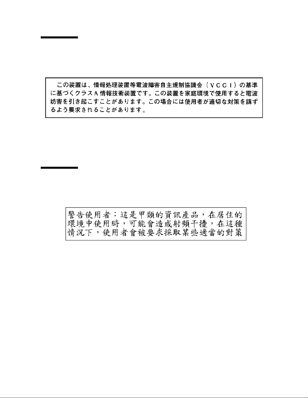
The following compliance statement in Japanese pertains to VCCI EMI regulations:
English translation: This is a Class A product based on the Technical Requirement of
the Voluntary Control Council for Interference by Information Technology (VCCI). In a
domestic environment, this product may cause radio interference, in which case the
user may be required to take corrective actions.
Taiwan Warning Label Statement
The following warning label statement pertains to BSMI regulations in Taiwan, R.O.C.:
English translation: This is a Class A product. In a domestic environment, this product
may cause radio interference, in which case, the user may be required to take adequate
measures.
20 T9840 User’s Reference Manual • September 2008 Revision YA • 95739
Page 23

Internal Code License Statement
The following is the Internal Code License Agreement from StorageTek:
NOTICE
INTERNAL CODE LICENSE
PLEASE READ THIS NOTICE CAREFULLY BEFORE INSTALLING AND OPERATING THIS EQUIPMENT. THIS
NOTICE IS A LEGAL AGREEMENT BETWEEN YOU (EITHER AN INDIVIDUAL OR ENTITY), THE END USER,
AND STORAGE TECHNOLOGY CORPORATION (“STORAGETEK”), THE MANUFACTURER OF THE
EQUIPMENT. BY OPENING THE PACKAGE AND ACCEPTING AND USING ANY UNIT OF EQUIPMENT
DESCRIBED IN THIS DOCUMENT, YOU AGREE TO BECOME BOUND BY THE TERMS OF THIS AGREEMENT.
IF YOU DO NOT AGREE WITH THE TERMS OF THIS AGREEMENT, DO NOT OPEN THE PACKAGE AND USE
THE EQUIPMENT. IF YOU DO NOT HAVE THE AUTHORITY TO BIND YOUR COMPANY, DO NOT OPEN THE
PACKAGE AND USE THE EQUIPMENT. IF YOU HAVE ANY QUESTIONS, CONTACT THE AUTHORIZED
STORAGETEK DISTRIBUTOR OR RESELLER FROM WHOM YOU ACQUIRED THIS EQUIPMENT. IF THE
EQUIPMENT WAS OBTAINED BY YOU DIRECTLY FROM STORAGETEK, CONTACT YOUR STORAGETEK
REPRESENTATIVE.
1. Definitions: The following terms are defined as
follows:
a. “Derivative works” are defined as works based
upon one or more preexisting works, such as a
translation or a musical arrangement, or any other
form in which a work might be recast, transformed,
or adapted. A work consisting of editorial revision,
annotations, elaboration, or other modifications
which, as a whole, represent an original work of
authorship, is a Derivative work.
b. “Internal Code” is Microcode that (i) is an integral
part of Equipment, (ii) is required by such
Equipment to perform its data storage and retrieval
functions, and (iii) executes below the user interface
of such Equipment. Internal code does not include
other Microcode or software, including data files,
which might reside or execute in or be used by or in
connection with such Equipment, including,
without limitation, Maintenance Code.
c. “Maintenance Code” is defined as Microcode and
other software, including data files, which might
reside or execute in or be used by or in connection
with Equipment, and which detects, records,
displays, and/or analyzes malfunctions in the
Equipment.
d. “Microcode” is defined as a set of instructions
(software) that is either imbedded into or is to be
loaded into the Equipment and executes below the
external user interface of such Equipment.
Microcode includes both Internal Code and
Maintenance Code, and might be in magnetic or
other storage media, integrated circuitry, or other
media.
2. The Equipment you have acquired by purchase or
lease is manufactured by or for StorageTek and
contains Microcode. By accepting and operating this
Equipment, you acknowledge that StorageTek or its
licensor(s) retain(s) ownership of all Microcode,
as well as all copies thereof, that might execute
in or be used in the operation or servicing of the
Equipment and that such Microcode is
copyrighted by StorageTek or its licensor(s).
3. StorageTek hereby grants you, the end user of the
Equipment, a personal, nontransferable (except as
permitted in the transfer terms below), nonexclusive
license to use each copy of the Internal Code (or any
replacement provided by StorageTek or your
authorized StorageTek distributor or reseller) which
license authorizes you, the end user, to execute the
Internal Code solely to enable the specific unit of
Equipment for which the copy of Internal Code is
provided to perform its data storage and retrieval
functions in accordance with StorageTek’s (or its
licensor’s) official published specifications.
4. Your license is limited to the use of the Internal Code
as set forth. You might not use the Internal Code for
any other purpose. You might not, for example, do
any of the following:
(i) access, copy, display, print, adapt, alter,
modify, patch, prepare Derivative works of,
transfer, or distribute (electronically or
otherwise) or otherwise use the Internal Code;
(ii) reverse assemble, decode, translate,
decompile, or otherwise reverse engineer the
Internal Code (except as decompilation might be
expressly permitted under applicable European
law solely for the purpose of gaining
information that allows interoperability when
such information is not otherwise readily
available); or
95739 • Revision YA Notices 21
Page 24

(iii) sublicense, assign, or lease the Internal Code
or permit another person to use such Internal
Code, or any copy of it.
5. Nothing in the license set forth above or in this entire
Notice shall convey, in any manner, to you any license
to or title to or other right to use any Maintenance
code, or any copy of such Maintenance Code.
Maintenance Code and StorageTek’s service tools and
manuals might be kept at your premises, or they
might be supplied with a unit of Equipment sent to
you and/or included on the same media as Internal
Code, but they are to be used only by StorageTek’s
customer service personnel or those of an entity
licensed by StorageTek, all rights in and to such
Maintenance Code, service tools and manuals being
reserved by StorageTek or its licensors. You agree that
you shall not use or attempt to use the Maintenance
Code or permit any other third party to use and access
such Maintenance Code.
6. You, the end user, agree to take all appropriate steps
to ensure that all of your obligations set forth in this
Notice are extended to any third party having access
to the Equipment.
7. You might transfer possession of the Internal Code to
another party only with the transfer of the Equipment
on which its use is authorized, and your license to use
the Internal Code is discontinued when you are no
longer an owner or a rightful possessor of the
Equipment. You must give such transferee all copies
of the Internal Code for the transferred Equipment
that are in your possession, along with a copy of all
provisions of this Notice.
Any such transfer by you is automatically
(without further action on the part of either
party) expressly subject to all the terms and
conditions of this Notice passing in full to the
party to whom such Equipment is transferred,
and such transferee accepts the provisions of this
license by initial use of the Internal Code. You
cannot pass to the transferee of the Equipment
any greater rights than granted under this
Notice, and shall hold StorageTek harmless from
any claim to the contrary by your transferee or
its successors or assigns. In addition, the terms
and conditions of this Notice apply to any copies
of Internal Code now in your possession or use
or which you hereafter acquire from either
StorageTek or another party.
8. You acknowledge that copies of both Internal Code
and Maintenance Code might be installed on the
Equipment before shipment or included with the
Equipment and other material shipped to you, all for
the convenience of StorageTek’s service personnel or
service providers licensed by StorageTek, and that
during the warranty period, if any, associated with the
Equipment, and during periods in which the
Equipment is covered under a maintenance contract
with StorageTek or service providers licensed by
StorageTek, both Internal Code and Maintenance Code
might reside and be executed in or used in connection
with such Equipment, and you agree that no rights to
Maintenance Code are conferred upon you by such
facts.
StorageTek or the licensed service provider
might keep Maintenance Code and service tools
and manuals on your premises but they are to be
used only by StorageTek’s customer service
personnel or those of service providers licensed
by StorageTek. You further agree that upon
(i) any termination of such warranty period or
maintenance contract period; or
(ii) transfer of possession of the Equipment to
another party, StorageTek and its authorized
service providers shall have the right with
respect to the affected Equipment to remove all
service tools and manuals and to remove or
disable all Maintenance Code and/or replace
Microcode which includes both Internal Code
and Maintenance Code with Microcode that
consists only of Internal Code.
22 T9840 User’s Reference Manual • September 2008 Revision YA • 95739
Page 25
CHAPTER
1
Overview
This chapter provides an overview of the T9840 Tape Drive family.
Tape Drive
The T9840 Tape Drive is designed for fast-access to data stored on a midpoint loading
tape cartridge. Four drive models are available for the enterprise and client-server
environments. The T9840A and T9840B have a 20
The T9840C has a cartridge capacity of 40
T9840D has a cartridge capacity of 75
the tape cartridge, see
“Cartridges” on page 30.
GB, uncompressed. The encryption-capable
GB, uncompressed. For more information about
GB, uncompressed cartridge capacity.
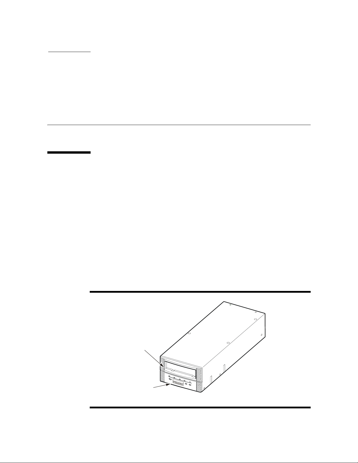
The drive front panel (FIGURE 1-1) has a tape load/unload slot and an operator panel for
manual control. See Chapter 2, “Operator Controls” for detailed information on
operator panel controls and indicators.
The drive rear panel has connectors for power, host interface, library interface, and
maintenance (not available on the T9840A). An encryption status LED is present on the
rear panel of the T9840D.
FIGURE 1-1 T9840 Tape Drive Front Panel
TAPE
LOAD/UNLOAD
SLOT
OPERATOR
PANEL
C53070
95739 • Revision YA 23
Page 26

Tape Drive
Use of the RJ45 maintenance port on a non-encrypiton drive is restricted to Sun service
personnel only.
Note – Customer attachment to the maintenance port of a non-encrypiton drive has
caused problems. Sun neither supports nor assumes any responsibility for
unauthorized use of the maintenance port by non-Sun personnel.
Encryption
Encryption is based on the science of cryptography and is one of today’s most effective
ways to achieve data security. To read an encrypted file, you must have access to the
key that enables the drive to decipher the data.
The T9840D tape drive employs a device-based (or data-at-rest) encryption solution.
The drive is shipped from the factory encryption-capable, but not encryption-enabled.
You must explicitly enable the drive for encryption.
Note – A tape drive that has not been enabled for encryption can neither read nor
append to any encrypted data cartridge.
An encryption-enabled drive can:
■ Write to the data cartridge in encrypted mode only (by using its assigned write key)
■ Read an encrypted data cartridge, if it has the proper read key
■ Read non-encrypted data cartridges
■ Format tape cartridges
An encryption-enabled drive cannot:
■ Append (write) to a non-encrypted data cartridge
■ Mix encrypted and non-encrypted data on the same cartridge
Encryption Resources
For additional information on the encryption capabilities and features, refer to:
■ Crypto Key Management System, Installation and Service Manual, PN 3161949xx
■ Crypto Key Management System, System Administrator Guide, PN 3161951xx
24 T9840 User’s Reference Manual • September 2008 Revision YA • 95739
Page 27
Encryption Status LED
C54103
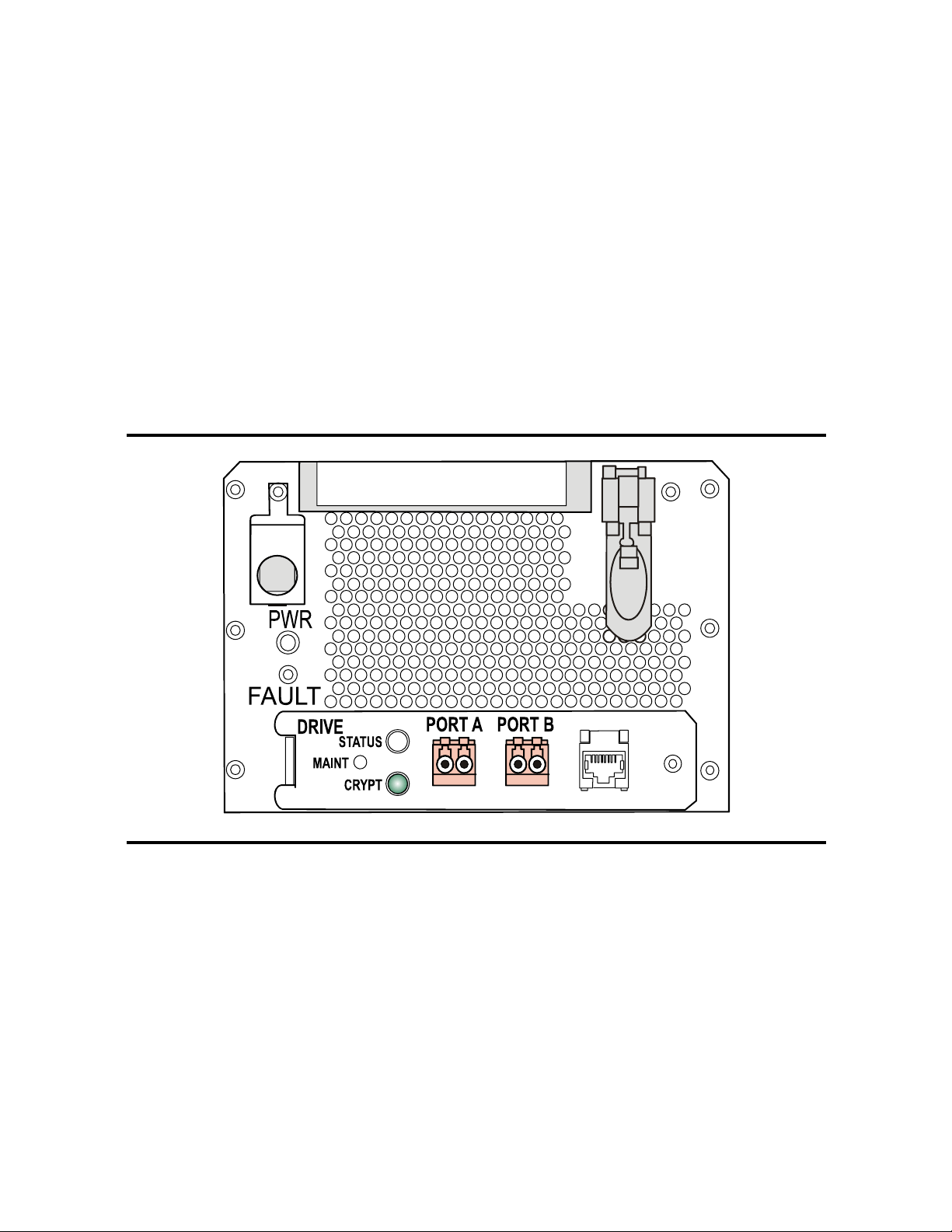
Encryption-capable drives have a tri-color, encryption-status LED on the rear panel, see
TABLE 1-1 on page 26 for an explanation of the status indications. Drive trays that fully
enclose the drive usea light pipe to transfer the LED indication to the rear of the tray
(see the
If the encryption status LED is green, it indicates that the drive is encryption capable,
but not encryption enabled. In this state, the drive functions only in a non-encryption
safe mode, and cannot read/write encrypted data cartridges. However, the drive can
function normally for non-encryption tasks.
Once the drive is encryption enabled, the LED turns red to indicate that the drive is
armed and functioning in the encryption mode. In this state, the drive can read/write
encrypted data cartridges. The drive can also read non-encrypted data cartridges, but
cannot write to non-encrypted data cartridges.
FIGURE 1-2 Encryption Status LED (SL8500 Library Drive Tray)
CRYPT label in the figure below).
Tape Drive
95739 • Revision YA Chapter 1 Overview 25
Page 28

Configurations
The following table interprets the various states of the encryption status LED. Refer to
TABLE 1-1 Encryption Status LED State Descriptions
LED State Mode Description
Green Safe Encryption capable, but not enabled.
Red Armed Encryption enabled/active.
Slow flashing Green
Slow flashing Red
Amber Requires media key.
Slow flashing Amber
3
Cycling
1. Slow flash (1 cycle per second)
2. Drive is no longer capable of unencrypted write operation once encryption has been enabled.
3. The LED continuously cycles through all three colors at the slow flash rate.
the Crypto Key Management documentation for additional information.
Normal-unencrypted drive write/read cartridge operations.
Ready to encrypt.
1
1
1
2
Reset
Zeroed Media, device, and enabling keys missing.
Encryption previously enabled, but requires keys.
Drive is capable read-only, unencrypted cartridge operations.
Encryption read/write cartridge operation in progress.
Requires device key.
The drive is unusable, and must be returned to manufacturing.
Configurations
T9840 Tape Drives are available in desktop, rack-mountable, and library-attached
configurations.
Desktop and Rack-mountable Drive Units
Both the desktop and rack-mount configurations, shown in FIGURE 1-3 on page 27, feature
manual tape cartridge loading. The desktop version (T9840A/B only) comprises a single
drive and a power supply mounted within a cabinet with rubber feet. The rack-mount
version includes a single drive or dual drives plus power supplies in a chassis (tray).
26 T9840 User’s Reference Manual • September 2008 Revision YA • 95739
Page 29
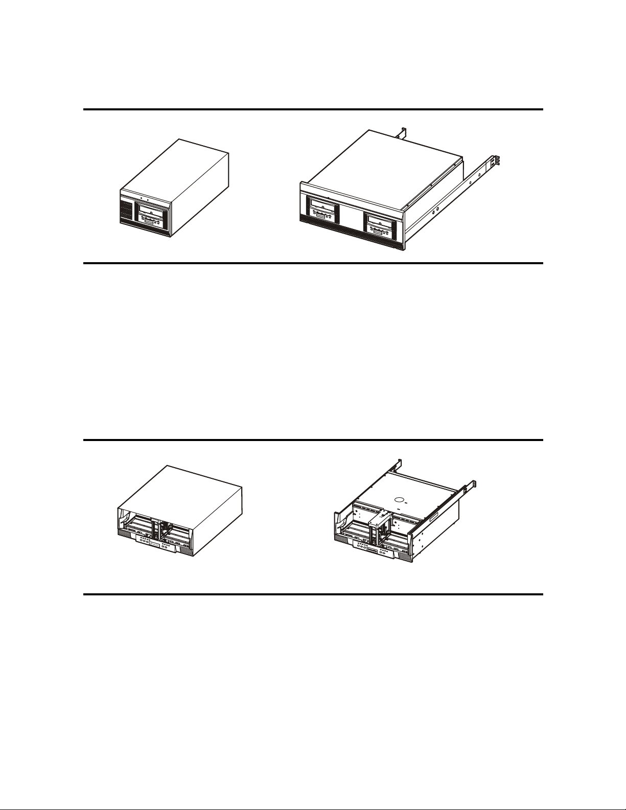
FIGURE 1-3 T9840 Desktop and Rack-mount Units
Configurations
Desktop Unit
Up to six single-drive and/or dual-drive trays may coexist in a single cabinet, such as
the stand-alone CBNT42U rack. The tray fits in a standard 483-mm (19 in.) rack with a
depth of at least 780 mm (30.75 in).
Cartridge Scratch Loader Drive Units
The cartridge scratch loader (CSL) configuration (T9840A only) features
manual/automatic/system sequencing of up to six tape cartridges. Both the CSL
desktop and rack-mountable units are shown in the following figure.
FIGURE 1-4 CSL Desktop and Rack-mount (T9840A)
Rack-Mount Tray
C54002
CSL Desktop Unit (T9840A)
CSL Rack-Mount Tray (T9840A)
C54003
The desktop version comprises a single drive, power supply, and loader mechanism
contained in a cabinet with rubber feet. The rack-mountable version differs only in the
cover, and the addition of rail assembles for rack mounting. A rack, such as the
CBNT42U, can hold up to six CSLs or combinations of CSLs and manual load drive
units.
95739 • Revision YA Chapter 1 Overview 27
Page 30
Configurations
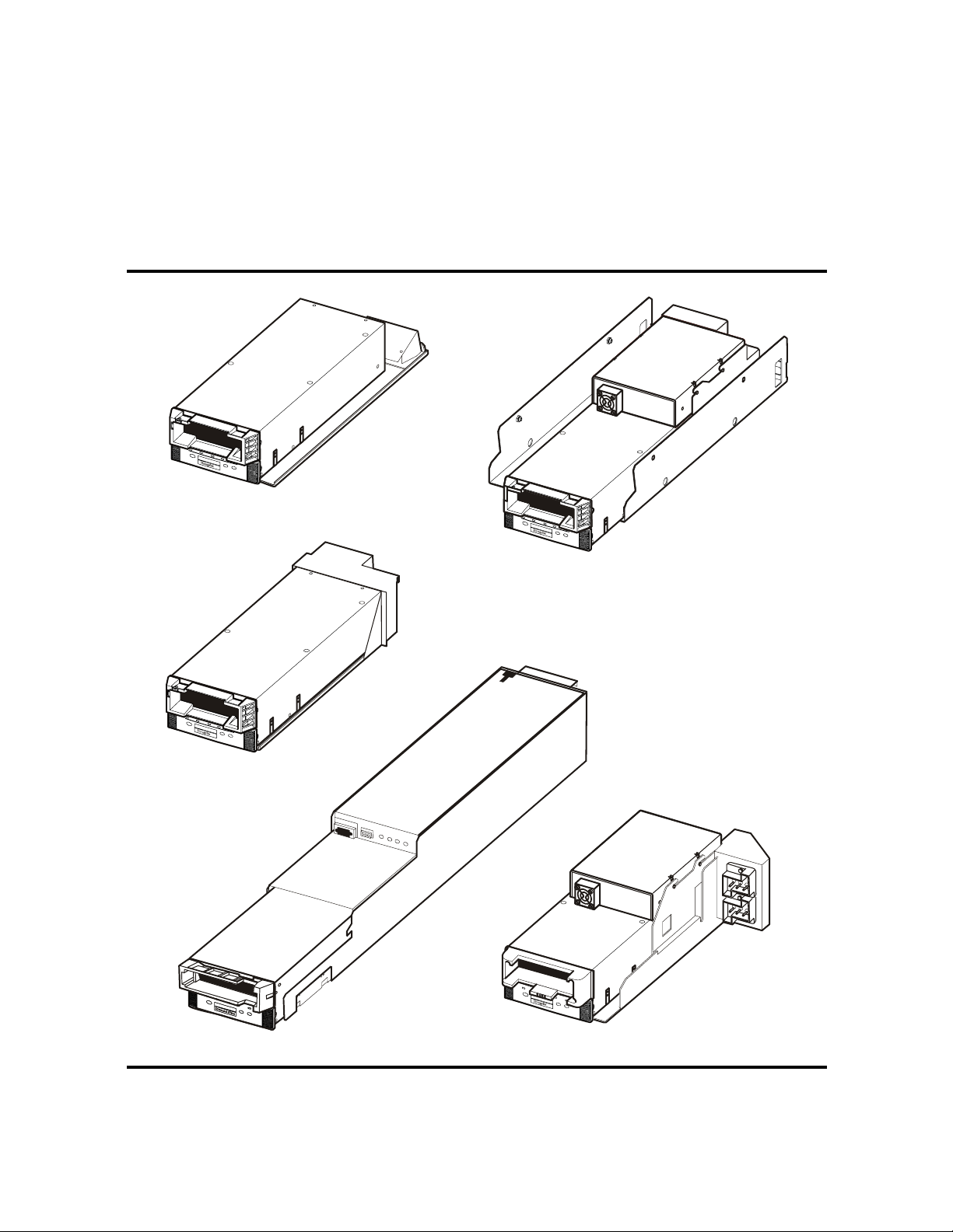
Library Attached Configurations
The drive is available in configurations for various libraries; several are shown in the
following figure.
Refer to the appropriate library documentation for additional information.
FIGURE 1-5 T9840 Tape Drive Library Attached Configurations
Tra y Assembly for 9310/9360/9740/L5510
Tray Assembly for 9738 (T9840A)
Tray Assembly for 9710 (T9840A/B)
Tray Assembly for SL8500
Tray Assembly for Libraries L180/L700/L1400
C53886
28 T9840 User’s Reference Manual • September 2008 Revision YA • 95739
Page 31

Interfaces
Interfaces
Host interfaces for the T9840 Tape Drive include:
■ Enterprise Systems Connection (ESCON) [single port connector]
■ Fibre Channel (FC)
■ Fibre Connection (FICON)
■ Small computer system interface (SCSI) - T9840A/B only [single port connector]
Note – Not all interfaces are available for all configurations, see TABLE A-8 on page 92.
The T9x40 tape drives support connection of both ports in accordance with ANSI Fibre
Channel specifications. Refer to the InterNational Committee on Information
Technology Standards [INCITS] documents:
■ SCSI Primary Commands -3, Section 5.6
■ Fibre Channel Protocol -3
Note – The drive will support two hosts, provided that they honor the
“reserve/release” or the “persistent reserve/release” specifications.
95739 • Revision YA Chapter 1 Overview 29
Page 32
Cartridges
W
Cartridges
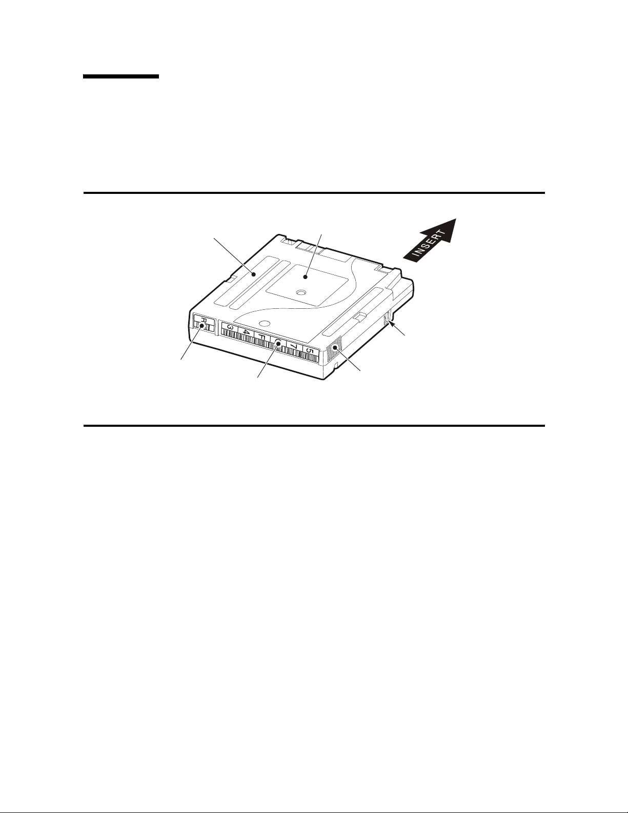
The 9840 data cartridge shown in the figure below has the supply and takeup reels
inside the cartridge which permits midpoint loading and fast access to data files.
FIGURE 1-6 9840 Tape Cartridge
MANUFACTURER
LABEL
AREA
CUSTOMER
LABEL
AREA
WRITE
PROTECT
SWITCH
MEDIA ID
LABEL
VOLSER
LABEL
REAR VIEW
FINGER
GRIPS
(FORWARD
POSITION IS
RITE PROTECTED)
C53069
The 9840 data cartridge has a typical capacity of:
■ 20 GB, uncompressed when written by a T9840A or T9840B drive
■ 40 GB when written by a T9840C drive (PRML data format)
■ 75 GB when written by a T9840D drive (PRML data format)
See TA BL E 1-2 on page 31 for information regarding read and write compatibility.
The 9840 cleaning cartridge is capable of 100 cleaning operations. The media
identification labels for 9840 Tape Cartridges have unique letters:
■ R - 9840 standard and VolSafe data tape cartridges
■ U - cleaning cartridge used with T9840A, T9840B, and T9840C drives
■ Y - cleaning cartridge used with the T9840D drive only
A variation of the data cartridge is available for VolSafe (append-only) use.
■ The manufacturer and media identification labels are yellow (9840A/B), green
(9840C), or purple (T9840D).
■ The write-protect switch is yellow (9840A/B), green (9840C), or purple (T9840D).
■ Model-unique dimple pattern on the bottom of the cartridge case.
Call 1-877-STK-TAPE (785-8273) to order media from the local Sun reseller or for media
pre-sales support. To place orders electronically, send an e-mail to:
[email protected], [email protected], or [email protected]
30 T9840 User’s Reference Manual • September 2008 Revision YA • 95739
Page 33

Mixed Media Management
Since T9840A, T9840B, T9840C, and T9840D drives use the same 9840 standard data
cartridge, you should take extra media management measures when:
■ T9840C drives co-exist in the same library system with T9840A/B drives
■ T9840D drives co-exist in the same library system with T9840A/B/C drives
The extra measures essentially involve creation and management of separate media
pools/sub-pools for:
■ T9840A/B formatted/written data cartridges
■ T9840C formatted/written data cartridges
■ T9840D formatted/written data cartridges
Guidelines for creation and maintenance of media pools/sub-pools are located in
TABLE 1-2 Cartridge Read/Write Compatibility
Compatibility
ACSLS, HSC, and independent software vender (ISV) documentation sets.
Drive Model
T9840A T9840B T9840C T9840D
Mixed Media Management
Read a cartridge formatted by: T9840A and
T9840B
Write or append data to a cartridge
formatted by:
T9840A and
T9840B
T9840A/B tape drives cannot read from a data cartridge written by either T9840C or
T9840D tape drive because of the higher-density formats, and must have an appropriate
drive firmware level to even identify the higher-density data cartridges:
■ T9840A:
■ R1.33.103, or higher, to identify a T9840C written cartridge
■ R1.41.105, or higher, to identify a T9840D written cartridge
■ T9840B:
■ R1.33.303, or higher, to identify a T9840C written cartridge
■ R1.41.305, or higher, to identify a T9840D written cartridge
■ T9840C - R1.41.505, or higher, to identify a T9840D written cartridge
Without the appropriate drive firmware level, a T9840A/B drive would consider a
higher-density formatted cartridge blank and available for scratch. T9840A/B drive
attempts to read the data from an identified higher-density data cartridge will fail.
T9840A and
T9840B
T9840A and
T9840B
T9840A,
T9840B, and
T9840C
T9840A,
T9840B,
T9840C, and
T9840D
T9840C T9840D
95739 • Revision YA Chapter 1 Overview 31
Page 34

Mixed Media Management
The T9840C or T9840D tape drive can read data from a tape cartridge written by a
T9840A/B tape drive in the low-density format, but does not append data to that
cartridge. An attempt to append a low-density data cartridge on a T9840C or T9840D
drive will fail, and sense byte data indicates an error (similar to that of a file-protected
data cartridge).
Note – For additional information about mixed-media management see “Cross-Density
MIR Processing”.
Media Information Region
The T9840 tape drives use information recorded on each tape cartridge to access and
manage that tape cartridge while it is loaded in the drive. This information is recorded
at the beginning of the tape in an area known as the Media Information Region (MIR).
The information contained in the MIR falls into two major categories:
■ Statistical Counters
Statistical counters include read/write activity, error activity, cumulative mounts and
other information that reflects tape cartridge usage.
■ Data Pointers
The data pointer information is basically a directory (map) used to locate the data on
the physical tape media. Since user data is compressed and written in drive
controlled blocks on the tape, a map is needed to efficiently locate the data after it is
written. This map provides an index between user block ID's and the physical block
on the tape media. Once the data is written, the drive accesses this map to optimize
access to the user data.
A read to a user block ID is translated to the physical location on the tape media, and
the drive determines the quickest method to read the block. If the block is some
physical distance from the current location, a calculation results in a high-speed
locate to the block location and is followed by a normal speed read.
The existence of the MIR is usually transparent to the user unless the MIR has a
problem. This could occur if the MIR update fails during a dismount. The impact of an
invalid MIR occurs in several areas. Since the MIR enables high speed positioning, an
invalid MIR forces all operations to a slow speed mode. This has no impact on a
sequential read from the beginning of the tape. However, an operation that could use
high-speed locate defaults to a sequential slow speed read to the requested block,
which can result in a longer processing time.
An invalid MIR might be suspected if you observe poor performance on a specific tape
cartridge. The T9x40 drive also posts a 36B2 informational FSC whenever a tape
cartridge with an invalid MIR is loaded.
The following sections describe MIR processing and some potential implications of MIR
problems.
32 T9840 User’s Reference Manual • September 2008 Revision YA • 95739
Page 35

Mixed Media Management
Normal MIR Processing
Every time a tape cartridge is loaded, the MIR is read from the tape media and saved in
the drive memory. When the MIR is loaded in drive memory, an invalid flag is written
in the tape-resident MIR. The tape-resident MIR is marked invalid because it does not
reflect results of activity in the current mount session. All subsequent MIR accesses
during the current mount session are saved in the memory-resident MIR.
When the tape cartridge is unloaded, as part of the unload routine, the memoryresident MIR information is written to the tape-resident MIR and the MIR invalid flag
is turned off. A copy of the memory-resident MIR is stored in the drive’s persistent
memory (EEPROM) and used should the MIR fail to be written because of a power
failure or firmware problem (SNO or should not occur).
Cross-Density MIR Processing
Whenever a data cartridge is loaded that was written in a data density format that is
different from the one used when the drive writes, model-specific MIR processing
occurs. The following explanations cover:
■ T9840D tape drive loaded with a lower-density cartridge
■ T9840C tape drive loaded with aT9840D-written data cartridge
■ T9840C tape drive loaded with a T9840A/B-written data cartridge
■ T9840A/B drive loaded with a high-density tape cartridge
T9840D Tape Drive Loaded With a Lower-Density Cartridge
When the T9840D drive detects that a data cartridge is loaded, the drive first looks in
the designated location for a T9840D MIR. If a T9840D MIR is not found, the drive then
checks for a T9840C MIR and, if its not found, it then checks for a T9840A/B MIR. The
processing for these operations is described in the sections below. If the MIR cannot be
read, the T9840D drive attempts to recover its contents using any portions of the MIR
that can be read and the contents of the Format Identity Burst (FIB).
Note – The FIB is written in a format that can be read by T9840C and T9840A/B drives
if they have an appropriate level of firmware.
The T9840D uses a memory-resident copy of the MIR to access user data pointers for
read-only functions. Statistical counters are continuously updated in the memoryresident MIR with any drive activity.
When the data cartridge is unloaded, the T9840D drives writes the FIB to the highdensity MIR location.
Notes:
■ When the T9840D drive identifies the data cartridge as a low-density data format,
i.e., written by a T9840C or T9840A/B, it displays Ready L on its operator panel.
■ The T9840D tape drive cannot correct or cause an invalid MIR on a T9840C
written data cartridge. A T9840C MIR can only become invalid during a mount on
a T9840C drive.
95739 • Revision YA Chapter 1 Overview 33
Page 36

Mixed Media Management
■ The T9840D tape drive cannot correct or cause an invalid MIR on a T9840A/B
■ If a T9840C or T9840A/B written data cartridge has an invalid MIR, its contents
T9840C tape Drive Loaded With a T9840D Data Cartridge
The T9840C drive will not be able to read the MIR written by a T9840D drive. Because
it was written by a T9840D there will be no T9840A/B MIR. The T9840C drive will read
the Format Identity Burst (FIB) written by the T9840D tape drive.
Note – The T9840C drive identifies the tape cartridge as high-density data format, and
Ready H (high-density) appears in the T9840C operator panel display.
Since the T9840D written data cannot be read by the T9840C tape drive, the only actions
available to the drive are:
■ Unload the data cartridge
■ Reclaim the data cartridge
written data cartridge. A T9840A/B MIR can only become invalid during a mount
on a T9840A/B drive.
cannot be read into the T9840D drive's memory and the user data pointer
information will be unavailable. This causes a performance degradation.
If the data cartridge is reclaimed, the T9840C drive will include the statistical
information from the T9840D FIB when it writes the T9840C MIR and FIB.
T9840C Tape Drive Loaded With a T9840A/B Data Cartridge
When a data cartridge is loaded into a T9840C, the drive first looks for a MIR at the
high-density MIR designated location; and will not find a MIR if the data cartridge is in
low-density data format. The high-density MIR location will be blank if it is the first
time the low-density data cartridge is loaded into a T9840C drive. This causes the drive
to look at the low-density MIR designated location, where it finds a MIR and reads it
into drive memory (invalid flag is not set).
The T9840C drive uses the memory-resident MIR for user data pointers for read-only
functions. During the first mount session, the drive captures statistical counters from
the MIR into a memory area called the Format Identity Burst (FIB), and continues to
build it with drive activity.
Note – The FIB is written in a special format which can also be read by T9840A/B
drives with the appropriate drive firmware level.
During the unload routine, the T9840C drive writes the FIB to the high-density MIR
designated tape location. The tape-resident, low density MIR remains intact and valid.
Notes:
■ The T9840C drive identifies the tape cartridge as low-density data format, which
results in the display of Ready
■ The T9840C tape drive cannot cause nor correct an invalid MIR on a low-density
data cartridge. A low-density MIR can only become invalid during a mount on a
T9840A/B tape drive.
L (low-density) on the T9840C operator panel.
34 T9840 User’s Reference Manual • September 2008 Revision YA • 95739
Page 37

Mixed Media Management
■ If a low-density data cartridge MIR is invalid, it is not read into the T9840C drive
memory, and not available for user data pointer information. Therefore, T9840C
performance for a low-density data cartridge with an invalid MIR is degraded.
■ Since a T9840C tape drive cannot correct nor rebuild a low-density data cartridge
invalid MIR, the only options for increasing performance are:
i. Migrate the data to a high-density format cartridge, using a copy utility with a
second T9840C drive
ii. Rebuild the MIR with a T9840A/B tape drive
iii. Operate with degraded performance
On subsequent mounts, the T9840C drive first sees the tape-resident FIB, identifies the
tape cartridge as low-density, and reads the low-density MIR into drive memory. At
dismount, the T9840C updates the tape-resident FIB with cumulative data, including
newer statistical data from the MIR, if the cartridge had been loaded into a T9840A/B
drive since the last mount in a T9840C drive.
T9840A/B Tape Drives
When a high-density data cartridge is loaded into a T9840A/B drive with appropriate
level firmware, the drive looks for a low-density MIR at the default location but finds a
Format Identity Burst (FIB), which identifies the cartridge as formatted in a highdensity. Since the T9840A/B drive cannot read nor write higher-density data,
subsequent normal read/write attempts will fail unless the cartridge is being reclaimed.
A T9840A/B drive cannot update statistical data, such as the mount/dismount count in
the FIB. Therefore, cumulative statistical data will not include mounts into a T9840A/B
drive as long as the tape cartridge is in high-density format.
The tape cartridge could be deliberately over-written in low-density data format from
the beginning-of-tape point, or reformatted to low-density data format by the offline
Drive Operation, Make Data Tape submenu. Either case over-writes the FIB with a lowdensity MIR, and erases the high-density MIR. Such a reformatted data cartridge is no
longer identifiable as a high-density data cartridge, but does include the statistical data
read from the FIB.
When a low-density data cartridge with a tape-resident FIB (created by a T9840C or
T9840D drive) is loaded into a T9840A/B drive with appropriate level firmware, the
MIR is read into drive memory and an invalid flag is written to the tape-resident MIR.
During the unload routine, the T9840A/B drive compares statistical data in the taperesident MIR with statistical data in the tape-resident FIB, and uses the latest data to
calculate the statistical data update into the new tape-resident MIR.
Notes:
■ The T9840A/B drive shows Ready H on the operator panel when a cartridge
written by a T9840C or T9840D drive is loaded.
■ If the last load was into a T9840A/B drive, the tape-resident MIR will contain the
latest statistical data; whereas, if the last load was into a T9840C or T9840D drive,
the tape-resident FIB contains the latest data.
■ In order to recognize a high-density data cartridge written by a T9840C or T9840D
drive, and to properly handle a low-density data cartridge that has been
previously loaded into a T9840C or T9840D drive, T9840A/B drives must have the
appropriate drive firmware level, see
“Mixed Media Management” on page 31.
95739 • Revision YA Chapter 1 Overview 35
Page 38

Mixed Media Management
■ If a T9840A/B drive has down level drive firmware, a high-density data cartridge
Exceptional MIR Processing
There are instances when the MIR process departs from the normal.
■ Write Protect
When the tape cartridge is write protected, neither the MIR nor FIB is rewritten and
statistical information for that mount is not captured. If the tape cartridge is in a
library that logically write protects the tape cartridge, the MIR is updated as normal
on each dismount.
■ Major Error/Power Off
If a tape cartridge is mounted and the drive SNO's (should not occur error) or loses
power, the drive memory-resident MIR is not written to the tape media. Instead after
IPL (initial program load), the drive will read the existing MIR on tape. Special data
is saved in EEPROM that will allow the existing MIR to be updated and rewritten to
the media with the valid flag set. Therefore, the MIR will contain all positioning
information up to the last mount and this tape will operate with mixed performance
until EOD is found. T9840A/B/C drives must have the appropriate drive firmware
level to update the MIR after a SNO or power loss, see
on page 31.
would be considered as a blank tape cartridge; and, a low-density data cartridge
would lose statistical data stored in the FIB during a previous mount into a
T9840C drive.
“Mixed Media Management”
Invalid MIR Correction
Once a tape cartridge has an invalid MIR, some action is required to correct it. An
invalid MIR can be corrected in several ways using the drive model that created the
cartridge (for example: a T9840A/B formatted cartridge in a T9840A/B drive or a
T9840C formatted cartridge in a T9840C drive).
1. Reading to the end of existing data (EOD) creates a complete and valid MIR. This is
done at normal read speeds and could take up to 45 minutes, for a full 9840 tape
cartridge.
2. Appending to the tape cartridge will also create a valid MIR, although a slow speed
read must first be done to the end of existing user data.
3. The Drive Operation Menu (offline) “Rebuild MIR” utility will sequentially read
from block ID 0 to the EOD. The MIR will be complete and valid when the tape
cartridge is unloaded (see
4. The Drive Operation Menu (offline) “Make Data Tape” utility will reformat the tape
cartridge with a valid MIR. However, all previous data will be lost (see
Cartridge” on page 76).
The memory-resident MIR is always rebuilt to the last block read, on-the-fly, during
normal read/write functions. When the partially rebuilt memory-resident MIR is
written to the tape during the download process, the invalid flag is reset because the
MIR is now partially valid. This can result in seemingly conflicting performance from a
single tape.
“Build MIR” on page 77).
“Reformat a
36 T9840 User’s Reference Manual • September 2008 Revision YA • 95739
Page 39

Mixed Media Management
Notes:
■ If a tape cartridge with a partially valid MIR is mounted for long periods of time
with locates to different locations, locate times will be inconsistent depending on
whether the locate is to a record already in the rebuilt MIR, or if some low speed
locate is required.
■ The longer the tape cartridge is mounted and the more activity occurs, the more
rebuilt the memory-resident MIR becomes. Once the EOD is reached, the MIR is
complete and valid.
95739 • Revision YA Chapter 1 Overview 37
Page 40

Mixed Media Management
38 T9840 User’s Reference Manual • September 2008 Revision YA • 95739
Page 41

CHAPTER
2
Operator Controls
Several methods are available that enable you to determine the state of the tape drive,
perform operator tasks, or view and alter drive configuration settings.
All T9840 drives have a physical operator panel. You can use this panel to access the
drive menu system, to view drive indicators, to access front panel switches, and to load
a tape cartridge. In the rack-mounted drive, you should always have clear access to the
panel.
For a library attached drive, you must open the library door to access the drive
operator panel. Several library models provide the capability to obtain information
about the drive from the library or a software application. The library console for the
SL8500 and SL3000 libraries is introduced in this chapter.
The T9840D tape drive is supported by the Virtual Operator Panel application (release
1.0.12 or higher). The VOP application is introduced in this chapter.
Information in chapters 3 and 4 of this document rely on use of the physical operator
panel.
95739 • Revision YA 39
Page 42
Front Panel
Front Panel
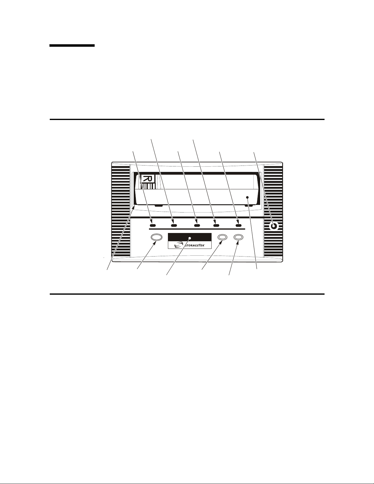
The T9840 tape drive front panel is the operator’s interface with the drive. The panel
features: a cartridge load/unload slot, four indicator lights, four switches, a manual
unload device, and an alphanumeric display with an optional tape bar (
FIGURE 2-1 T9840 Operator Panel
FIGURE 2-1).
LOAD/UNLOAD SLOT
POWER
INDICATOR
UNLOAD
SWITCH
ACTIVITY
INDICATOR
DISPLAY
CLEAN
INDICATOR
SERVICE
INDICATOR
MENU
SWITCH
IPL
SWITCH
SELECT
SWITCH
MANUAL
UNLOAD
DEVICE
TAP E
CARTRIDGE
C53117
Chapter 4, “Operator Tasks” describes how to use the switches to perform operations.
Chapter 5, “Indicators and Messages” describes how to interpret the indicators and
display messages.
Load/Unload Slot
The load/unload slot is the opening in the front panel that accepts 9840 Tape Cartridges
that you load by hand, that a T9840A CSL loads, or that a library robotic hand loads.
After a tape cartridge is inserted, the loader mechanism raises to engage the tape
cartridge and draw it into the loaded position. After an unload command, the loader
mechanism rewinds the tape to the mid-point and ejects the cartridge into the slot for
removal.
40 T9840 User’s Reference Manual • September 2008 Revision YA • 95739
Page 43

Indicators
TABLE 2-1 describes T9840 Tape Drive operator panel indicators.
TABLE 2-1 Operator Panel Indicators
Indicator Indication Explanation
Front Panel
power (green) Off:
Flashing:
Flashing does not stop:
On (steady):
activity (green) Off:
Flashing:
On (steady):
clean (amber) On (steady): Drive requires cleaning because:
service (red) Off:
Flashing:
On (steady):
Power is not applied.
Unit is powering up, performing IPL, or collecting dump data.
IPL failed.
Power applied and IPL complete.
Tape cartridge is not loaded.
Tape cartridge is loaded and the tape is moving.
Tape cartridge is loaded and the tape is stopped.
1. A firmware-defined length of tape has passed over the R/W
heads.
2. A read/write perm (permanent error) is detected, and at least
one-half the firmware-defined length of tape has passed over
the R/W heads.
See “Clean the Drive” on page 73 for use of cleaning cartridges.
Error(s) have not been detected.
Error(s) detected and dump data has been saved to the EEPROM.
The message DumpAgain? displays if the drive detects the same
Fault Symptom Code (FSC) within one minute. Manually initiate
IPL. If the IPL does not eliminate the problem, contact authorized
service personnel.
A hardware error is detected and the drive is not functional. If a
manually initiated IPL does not eliminate the problem, contact
authorized service personnel
Manual Unload Device
The manual unload device (MUD) is a mechanism to manually remove a tape cartridge
from the drive when:
■ The Unload switch action fails
■ Power is not available for the drive
You use a screwdriver to engage the MUD and position the cartridge to be manually
pulled out of the load/unload slot.
Note – Only qualified service personnel should operate the MUD.
95739 • Revision YA Chapter 2 Operator Controls 41
Page 44

Front Panel
Display
The operator panel has a 10 segment, alphanumeric display that indicates:
■ Drive status
■ Menu selections and configuration choices
■ Error messages and fault symptom codes
■ Host-generated messages
■ Tape bar, if activated
The display is formed by a horizontal array of 10 segments. Each segment is formed by
an array of 35 dots—five wide and seven high (
form an uppercase or lowercase alpha character, a numerical digit, or a special
character, such as an asterisk (*). When the tape bar is not activated, the lighted
segments and dots form text messages. The text messages may display steadily,
flashing, or alternating with other messages.
Tape Bar
The tape bar uses the operator panel display to show the amount of tape that has been
written and read. The tape bar is a configuration option that must be activated by
authorized service personnel. Once activated, it appears on the operator panel display
when the drive is reading or writing.
FIGURE 2-2 on page 43). Each array can
When the tape bar is activated, the segments and dots simultaneously show the
percentage of the total tape length that has been written and read. Each dot represents
2% of the tape length; each segment represents 10%.
Note – The tape bar gets its information from the media information region (MIR) on
the tape. The MIR is written to the tape when the tape is unloaded. If the MIR is bad,
the tape bar does not display. To rewrite the MIR, see “Build MIR” on page 77.
Write Bar
As data is written to tape, the lighted dots forming the write bar appear at the left side
of the display and advance to the right. The write bar uses the full height of the display.
As the dots fill the display, note that only every other dot is lighted. The point where
the write bar ends is the percentage of tape written.
Read Bar
As data is read from the tape, the read bar appears in the center of the write bar as a
single row of unlighted dots. This row is bordered above and below by single rows of
lighted dots. The read bar also begins at the left side of the display and advances to the
right. The point where the read bar ends is the percentage of tape that has been read.
FIGURE 2-2 on page 43 is a simplified and an actual view of a tape bar that shows a tape
that is 50% written and 34% read.
42 T9840 User’s Reference Manual • September 2008 Revision YA • 95739
Page 45
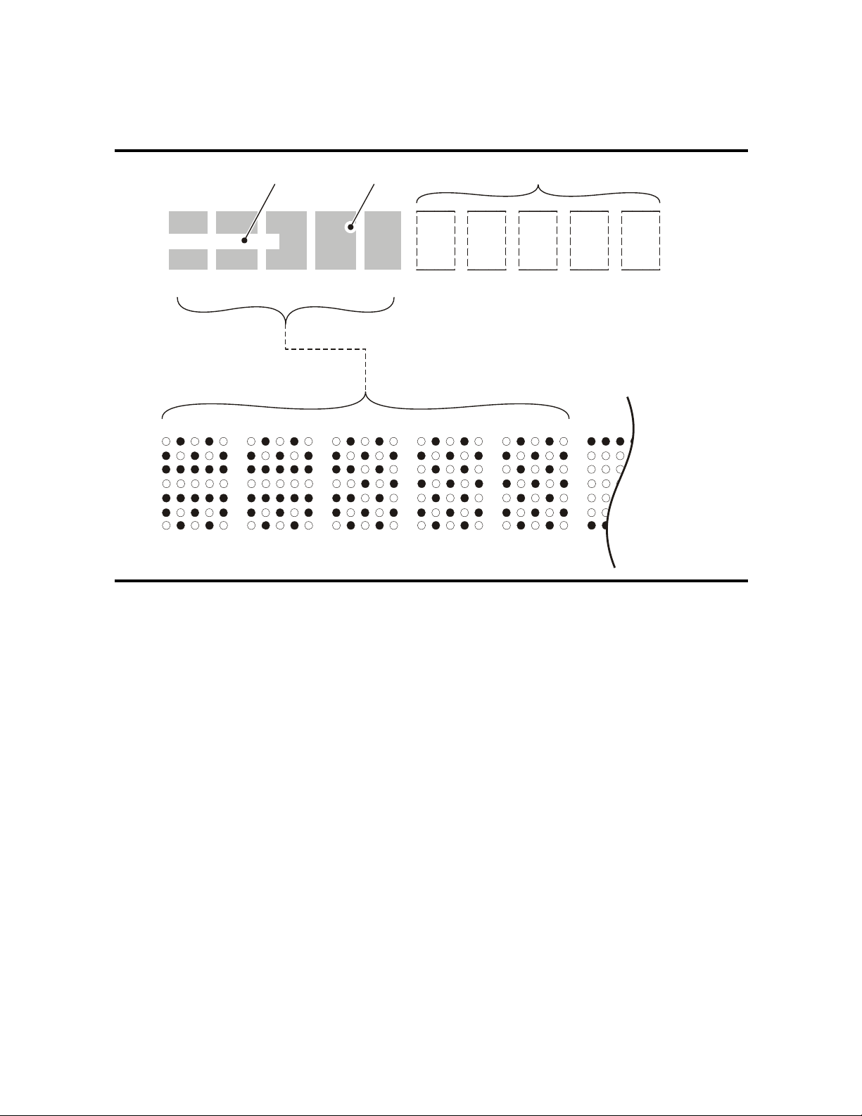
FIGURE 2-2 Tap e B ar
10% 20% 30% 50% 60% 70% 80% 90% 100%40%
Front Panel
READ BAR (24%) WRITE BAR (50%) UNWRITTEN AREA
10% 20% 30% 40% 50%
C53412
95739 • Revision YA Chapter 2 Operator Controls 43
Page 46

Front Panel
Switches
TABLE 2-2 describes T9840 operator panel switch functions.
TABLE 2-2 Operator Panel Switches
Switch Description
Menu Pressing the Menu switch accesses the menu system, steps through a series of
submenus, or answers No to a displayed question. Pressing the Menu switch the first
time causes the Online/Offline selection to display.
See x for information/guidance with the menu system.
Select Pressing the Select switch accesses a displayed submenu, steps through possible
options of a submenu, or answers Yes to a displayed question. When the drive is
Online and in a view only submenu, pressing Select is the same as pressing Menu.
IPL
Unload Pressing the Unload switch causes the tape cartridge to rewind, unthread, and
Pressing the IPL switch causes the drive to execute an initial program load (IPL)
sequence. During IPL, the drive firmware loads from non-volatile memory in an
EEPROM, to RAM. The same process occurs at power-on.
unload; ending with the tape cartridge ejected and retrievable.
If this switch is pressed during a write operation, the drive attempts to write the
remaining data before it unloads. A display of UnWr xxxx (meaning Unwritten Data,
where xxxx is a fault symptom code) means that the attempt failed and some data
remains unwritten to tape.
Note – Pressing Unload a second time causes the
unwritten data to be lost. Before you press
see UnWr xxxx on page 83.
Front panel switches are color coded by drive model:
T9840A - Yellow
T9840B - Purple
T9840C - Green
T9840D - Deep Purple
Unload again,
44 T9840 User’s Reference Manual • September 2008 Revision YA • 95739
Page 47
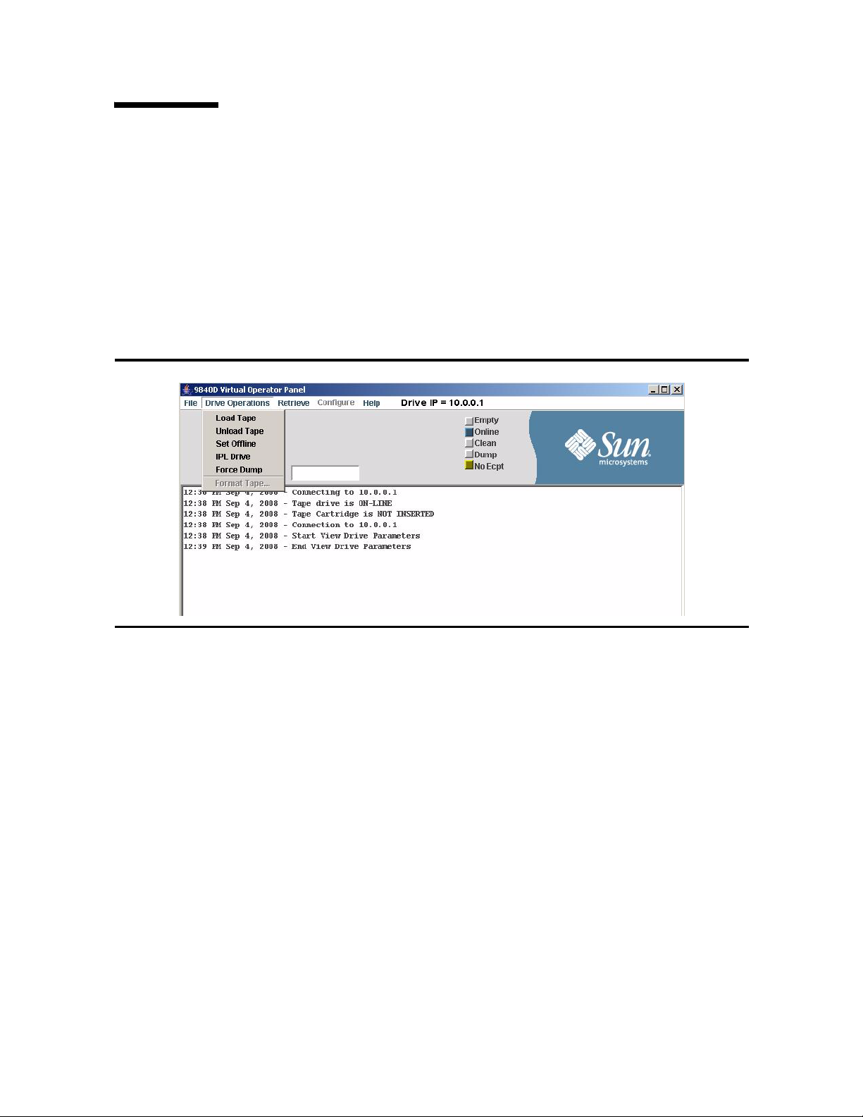
Virtual Operator Panel
The Virtual Operator Panel provides a graphical user interface to the T9840D tape
drive. The interface contains several menus, a set of indicators, two small display areas,
and a text pane (see
The Drive Operations menu provides commands to perform actions that are similar to
the physical operator panel switches.
The Retrieve and Configure menus provide commands to allow you to access functions
that are equivalent to the online and offline drive menu system.
FIGURE 2-3 Virtual Operator Panel
Virtual Operator Panel
FIGURE 2-3).
See the Virtual Operator Panel User’s Guide (P/N 96179) for a full description of the
application.
95739 • Revision YA Chapter 2 Operator Controls 45
Page 48
Library Controls/Indicators
6
Library Controls/Indicators
When a T9840 Tape Drive is attached to the SL3000 or SL8500 Modular Library System,
you cannot access the drive operator panel on the front of the drive without opening
the library door. The drive tray rear panel does provide some indicators and an
Ethernet port.
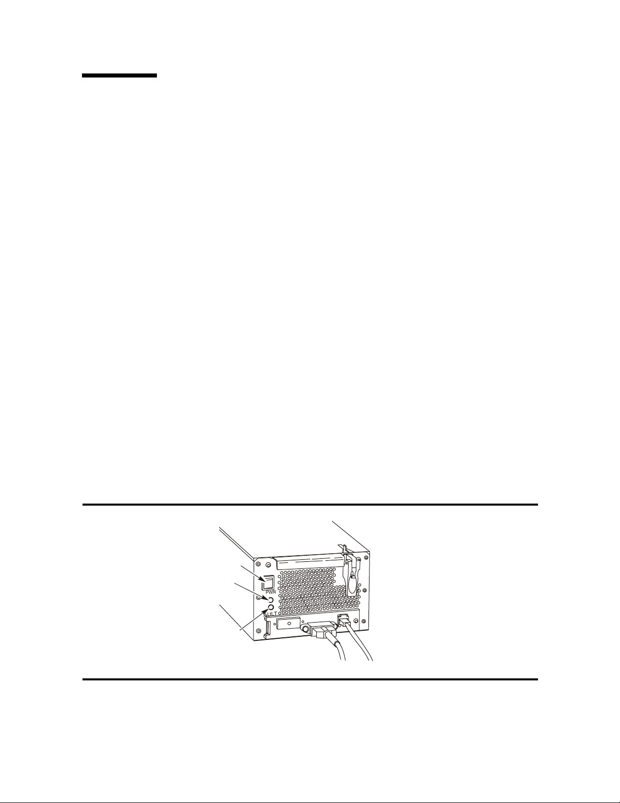
SL8500/T9x40 Drive Tray
FIGURE 2-4 illustrates the power switch and indicators on the rear panel of the
SL8500/T9x40 drive tray.
■ The power (PWR) switch is a momentary push-switch that manually changes the
state of the internal power supply PWA.
■ The green PWR LED indicates the power state of the tray:
Not lit: Power is not on, nor is 48 Vdc input power applied to the tray
Blinking: Power is not on, but 48 Vdc input power is applied to the tray
Steady: Power is on, and power supply output voltages are normal
■ The red FAULT LED indicates anomalies within either the internal power supply
PWA or with the drive tray fan assembly.
Notes:
■ Library firmware controls the drive tray power and indicators.
■ The red FAULT LED does not indicate drive-related anomalies.
■ Pressing the SL8500 drive tray PWR switch while the tray is powered does not
cause an interrupt signal to the library firmware. Wait at least 10-seconds before
you press the PWR switch to manually power-on the drive. Otherwise, the
library’s drive audit will be corrupted. When the red FAULT LED comes on (after
power-off), it is safe to re-push the PWR switch to reapply power to the drive tray.
FIGURE 2-4 SL8500/T9840 Drive Tray Rear Panel
P
W
R
c
h
i
t
w
S
P
W
R
L
E
D
T
L
U
F
A
D
L
E
9
0
4
5
C
46 T9840 User’s Reference Manual • September 2008 Revision YA • 95739
Page 49
StorageTek Library Console
Although you cannot access the T9840 Tape Drive Operator Panel to view menu items,
you can use the StorageTek Library Console (SLC), local or remote, to display data
pertinent to the attached drives.
Note – General guidance on using the SLC application is available within the SLC
“Help” function (click the ? button).
Drive Folder Top Level Display
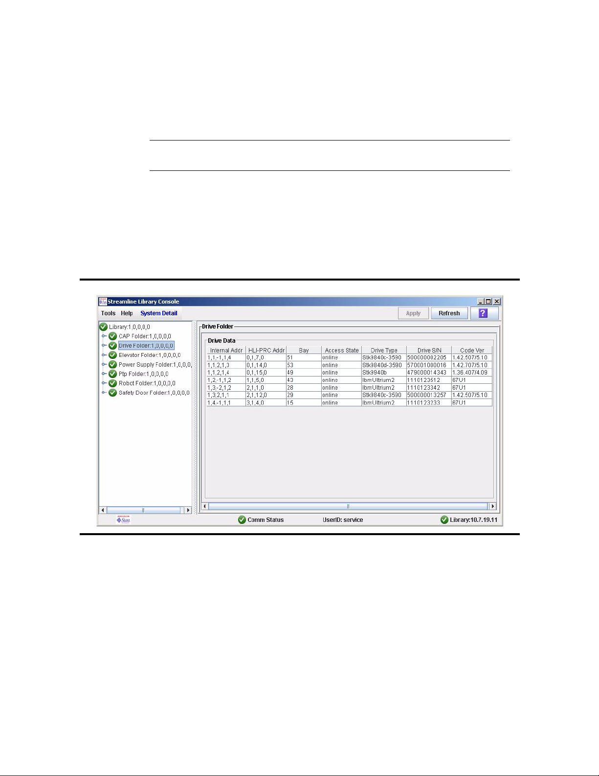
FIGURE 2-5 shows an overall summary of the Drive Folder. The left window pane
displays library folders in a tree format, which you can expand or collapse.
FIGURE 2-5 SL8500 SLC Drive Folder Display
Library Controls/Indicators
The right window pane summarizes drive data in a tabular format, whether you
expand or collapse the drive folder tree view. You can customize how the data is
displayed, by sorting the rows, relative to a selected column, and/or
reordering/resizing the columns.
Notes:
The “HLI-PRC Addr” column displays the host software logical address for the
drive, relative to the specific host software.
The “Access State” column is online/offline relative to the library drive
controller, and not relative to the drive, menu-driven online/offline.
95739 • Revision YA Chapter 2 Operator Controls 47
Page 50
Library Controls/Indicators
Drive Specific Displays
When you select an individual drive in the tree pane, the right pane changes to display
drive-specific data instead of the drive folder summary data.
You can view and use the SLC drive displays to develop reports to assist with the
analysis of drive-related problems.
In SLC 4.10, the Status, Properties, and Display tabs are available.
Note – The drive displays are evolving. New releases might contain an additional tab
or expanded information elements. Therefore, what is presented here is for illustrative
purposes only. No attempt will be made to keep the examples current.
Status
The “Code Ver” column displays the drive’s current firmware level, including
the drive interface sub-module level. Interface level 4.06, or higher is required
for proper SL8500 operation.
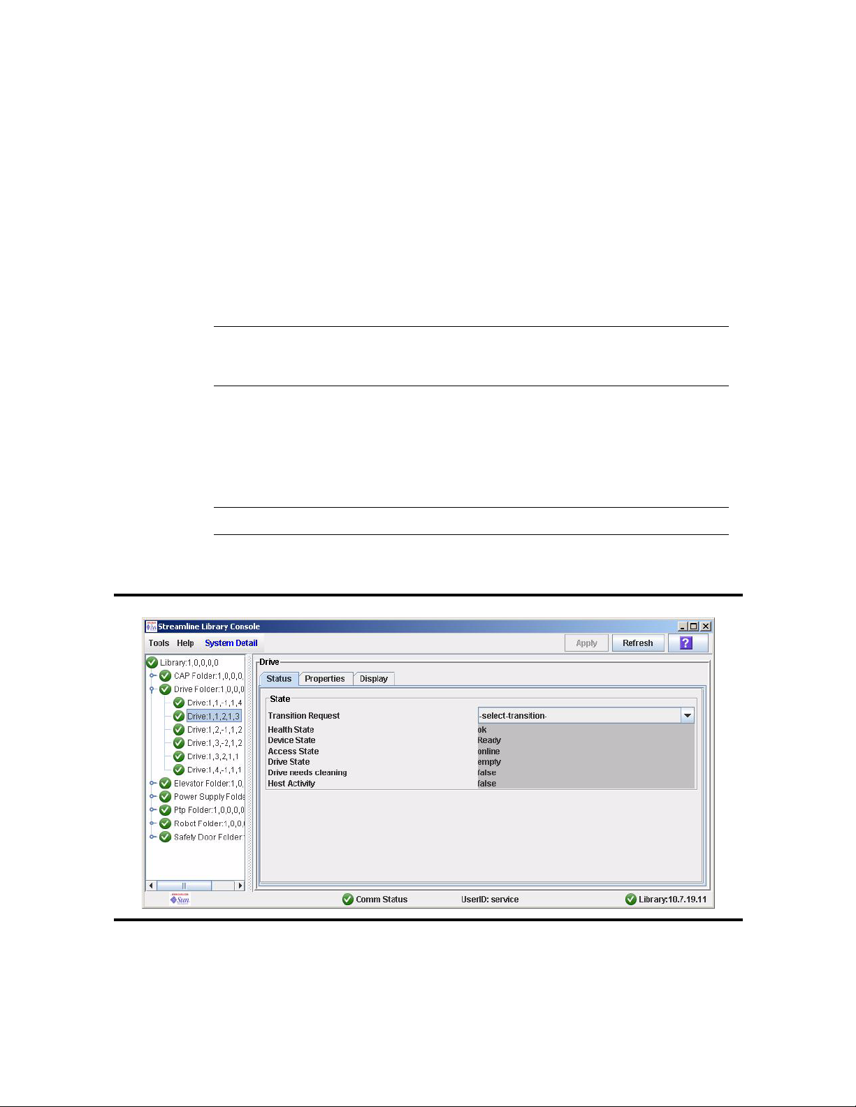
The tab shown in FIGURE 2-6 displays key drive status data: Health State, Device State,
Access State, Drive State, Drive needs cleaning, and Host activity.
Note – The list of states is variable based upon the drive, library, and SLC firmware.
FIGURE 2-6 SL8500 SLC Drive Status Tab
48 T9840 User’s Reference Manual • September 2008 Revision YA • 95739
Page 51
Properties
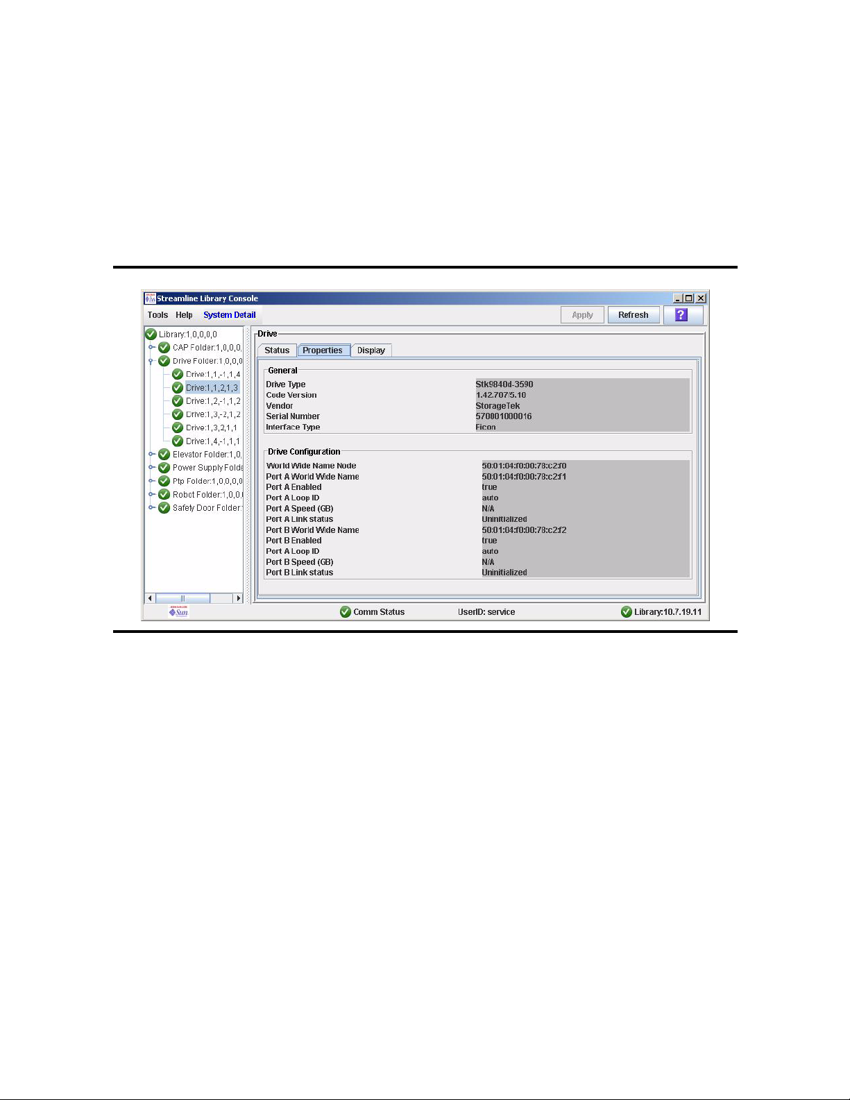
The General block in the Properties tab, FIGURE 2-7, displays some of the data from the
drive folder summary plus the drive interface type (not displayed in the summary).
The Drive Configuration block displays selected configuration items, such as WorldWide-Name (this is a dynamic value, dWWN, that is auto-set by the library relative to
the drive bay number).
FIGURE 2-7 SL8500 SLC Drive Properties Tab
Library Controls/Indicators
95739 • Revision YA Chapter 2 Operator Controls 49
Page 52

Library Controls/Indicators
Display
The Display tab, FIGURE 2-8, contains three sections: Network Data, Drive Virtual Op
Panel, and Drive LED Status.
FIGURE 2-8 SL8500 SLC Drive Display Tab
50 T9840 User’s Reference Manual • September 2008 Revision YA • 95739
Page 53
CHAPTER
3
Menus
The menu system provides the operator and service representative a means to
determine drive configuration settings, access drive utilities, and display the drive
firmware level at the drive operator panel. The menu system consists of information or
values, submenus, and options that appear in the display section of the operator panel
(see
“Display” on page 42). You navigate through the menu system by pressing the
Menu and Select switches on the operator panel (see “Switches” on page 44).
The menu system information and guidelines are provided in the following order:
1. “Menu Structure Overview”
2. “Online Menu Operation” on page 53
3. “Offline Menus” on page 62
Menu Structure Overview
The drive has two main menus:
■ When the drive is online, you will use the main menu primarily for viewing the
drive configuration settings.
■ When the drive is offline, you will use the main menu primarily for changing the
drive configuration settings or for performing drive operations.
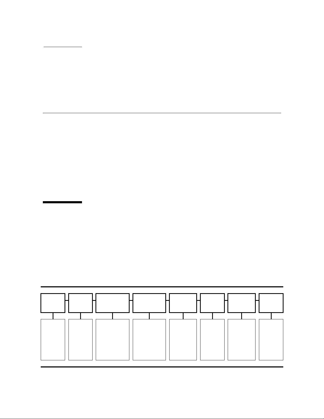
The illustration below is a high-level depiction of the common elements comprising the
main menu system. The left column shows the first item in the menu while the right
Online/ Port View/Change View/Change Drive Drive CSL Exit
Offline
Toggles
Online/
Offline
(no
submenus)
column shows the last item in the menu system.
Enable/
Disable
Toggles
Enable/
Disable
(no
submenus)
Configuration TCP/IP Operations Firmware Firmware Menu
Configuration
submenus
(Online - View)
(Offline Change)
TCP/IP
submenus
(Online - View)
(Offline Change)
Drive
utilities
submenus
(Offline
only)
Current
firmware
release
level
(no
submenus)
Current CSL
firmware
release level
(no
submenus)
Exits menu
system
(no
submenus)
95739 • Revision YA 51
Page 54

Menu Structure Overview
The drive is available with several data path interfaces. The main menu items do have
some variation based upon the particular interface, and those variations are presented
in later sections of this chapter.
Note – The Port Enable/Disable item does not appear as a main menu item for all
drive interfaces.
Although the illustration menu titles contain full words, the actual presentation on the
display is an abbreviation because the display is limited to ten characters. The
Configuration, TCP/IP, and Drive main menu items contain a ? as the last character in
the display. The ? signifies that a submenu is available.
You will use the Menu and Select switches to navigate through the menu system.
When you press the Menu switch on the operator panel, the first menu provides
selection of Online (default) or Offline menus.
■ Press the Select switch to toggle between online mode and offline mode as desired,
■ Press Menu (No) to bypass and advance to the next menu.
■ Press Select (Yes) to enter the submenus.
then press the
Menu switch to advance to the second menu item.
Note – If you press the Menu switch again, you will bypass the second menu item and
advance to the third menu item.
View/Change Configuration menus display drive configuration settings (view only)
when online, or allow drive configuration changes when offline. Press
advance the display to the next menu. Press
Select to enter the submenu.
Menu to
View/Change TCP Configuration menus display the drive Transmission Control
Protocol /Internet Protocol (TCP/IP) configuration settings (view only) when online, or
allow TCP/IP configuration changes when offline. Press
the next menu. Press
Select to enter the submenu.
Menu to advance the display to
Drive Operations menus (offline only) provide drive utilities. Press Menu to advance the
display to the next menu. Press
Select to enter the submenu.
The Drive Firmware menu (view only) displays the current drive firmware release level.
The Exit Menu allows you the choice to either return to the Online/Offline selection
menu or to exit the menu system. The last character in the Exit menu is a ? that signifies
that you must make a choice. Press
Select to exit the menu or press Menu to repeat the
main menu.
Note – The Virtual Operator Panel application provides the capability to view the
configuration settings of a T9840D tape drive. You might prefer to use this method
instead of the physical drive panel. See the Virtual Operator Panel User’s Guide (P/N
96179) for pertinent information.
52 T9840 User’s Reference Manual • September 2008 Revision YA • 95739
Page 55

Online Menu Operation
Online Menu Operation
When the drive is Online, the menus shown in FIGURE 3-1 on page 54 are available. Press
Menu to advance to the View Configuration menu.
■ View the drive configuration
■ View the TCP/IP configuration (N/A for the T9840A)
■ View the drive firmware level
■ View the ASIC firmware level (FICON drives only)
■ View the CSL firmware level
Note – Individual submenu items in the illustration are based upon the T9840A/B/C
drives using a code level prior to 1.42.x07.
The content of the figure was created before the T9840D tape drive was available. The
note on the TCP/IP menu does not apply to the T9840D drive because the drive
Ethernet port can be used with the Crypto Key Management System 2.0.
View Configuration Menu
The View Configuration menu is presented in more detail in the following sections:
■ “Fibre Channel View Configuration Menu Tree (T9840A/B/C)” on page 55
■ “Fibre Channel View Configuration Menu Tree (T9840D)” on page 56
■ “SCSI View Configuration Menu Tree” on page 57
■ “ESCON View Configuration Menu Tree” on page 58
■ “FICON View Configuration Menu Tree (T9840B/C)” on page 59
■ “FICON View Configuration Menu Tree (T9840D)” on page 60
The basic format is a text-based representation of the menu structure with indention
levels to indicate second and third levels (submenus). There is also a listing of options
and other pertinent information.
Note – Code level 1.42.x07 was used as the basis for documenting the View
Configuration menu. Specific menu item order and options might differ if your drive is
using an older or newer code level.
View TCP/IP Menu
The online (view) TCP/IP menu is presented on on page 61.
95739 • Revision YA Chapter 3 Menus 53
Page 56
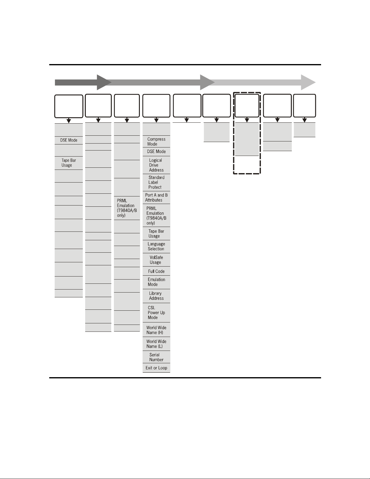
Online Menu Operation
V
FIGURE 3-1 Online Menus
View Drive
Configuration
(Fibre Channel)
Compress
Mode
Port A and B
Attributes
Language
Selection
VolSafe
Usage
Full Code
Emulation
Mode
Library
Address
CSL
Power Up
Mode
World Wide
Name (H)
World Wide
Name (L)
Serial
Number
Exit or Loop
View Drive
Configuration
(SCSI)
Compress
Mode
DSE Mode
SCSI ID
SCSI Target
Negotiation
Mode
SCSI
Speed
SCSI
Width
Tape B a r
Usage
Language
Selection
VolSafe
Usage
Full Code
Emulation
Mode
Library
Address
CSL
Power Up
Mode
World Wide
Name (H)
World Wide
Name (L)
Serial
Number
Exit or Loop
View Drive
Configuration
(ESCON)
Compress
Mode
DSE Mode
Logical
Drive
Address
Standard
Label
Protect
Limit Error
Recovery
Process
Tape B a r
Usage
Language
Selection
VolSafe
Usage
Full Code
Emulation
Mode
Library
Address
CSL
Power Up
Mode
Serial
Number
Exit or Loop
View Drive
Configuration
(FICON)
Interface
Selection
View TCP/IP
Configuration
NA T9X40A
See Note
iew Drive
Firmware
Level
Drive
Firmware
Release Level
Note:
The TCP/IP Configuration
submenus are for use
by authorized service
personnel only.
View ASIC
Firmware
Level
Stratix and
Excaliber
ASIC
Firmware
Release
Level
(T9840C & D
FICON ONLY)
View CSL
Firmware
Level
CSL
Firmware
Release Level
(None = No CSL)
Exit
Menu
Exits Menu
System
C53411
54 T9840 User’s Reference Manual • September 2008 Revision YA • 95739
Page 57

Online Menu Operation
Fibre Channel View Configuration Menu Tree (T9840A/B/C)
Use the online view configuration menu tree as a brief guide.
Online/Offline [Press Select to toggle, then press Menu to set.]
Port X YYY {A/B and ENA/DIS}
View CFG ? (View Configuration) {Press Select to enter, press Menu to bypass.]
Cmprss xxx {Yes/Off/No} (compression mode)
Full DSE x {Y/N} (data security erase mode)
SL Prot x {Y/N} (standard label protection mode)
View PrtA? (view current port attributes)
Hard PA xx {Y/N} (Physical Address)
PA=xx,ddd {PA=hex, decimal index} (valid only when Hard PA is yes)
Soft PA xx {HI/LO} (only when Hard PA is no)
MaxSz xxxx {2112/2048/1280/1024/768} (maximum data frame size)
A_I=xxxxxx (24-bit address ID - when port login is complete)
H=xxxxxxxx (first half, 64-bit port node world-wide-name)
L=xxxxxxxx (second half, 64-bit port node world-wide-name)
WWN Custom (only when custom or dynamic WWN is set)
View PrtB? (current port B attributes) (same sub-menus as port A)
Tape Bar x {Y/N} (tape completion indication)
English/Espanol/Francais/Italiano/Deutsch (current language)
VolSafe X {Y/N} (determines the VolSafe capability of the drive)
FullCode X {Y/N} (determines whether a full code image is in drive memory)
Emul xxxxx {STD/3590/*/*/3490E/*/*/*/*/*/*/*/*/*} (displays the active
emulation mode)
(*=special modes, used only when directed by Engineering or Tech Support)
Lib Adr xy {FF/00-13} (2-character hexidecimal library address) manufacturing
setting is FF and it must be changed to a valid address when the drive is
installed in a 9310 library.
CSL Xxxxxx {System/Auto/Manual} (CSL power up mode)
H=xxxxxxxx (first half, 64-bit drive node world-wide-name)
L=xxxxxxxx (second half, 64-bit drive node world-wide-name)
WWN Custom (only when custom/dynamic WWN is set)
S/N=xxxxxx {drive serial number} (last six-characters of drive DMOD)
Exit CFG ? (exit view configuration) [Press Select to exit, press Menu to
return to the View CFG ? submenu.]
95739 • Revision YA Chapter 3 Menus 55
Page 58

Online Menu Operation
Fibre Channel View Configuration Menu Tree (T9840D)
Use the online view configuration menu tree as a brief guide.
Online/Offline [Press Select to toggle, then press Menu to set.]
View CFG ? (View Configuration) [Press Select to enter, press Menu to bypass.]
Intf XXXXX {FICON/FCP}
View PrtA? (view current port attributes)
A=xxxxxxay (24-bit address ID - when port login is complete)
B=xxxxxxay (when viewing port B)
SFP module parameters {2G MM0300m/2G SM10.0k}
Hard PA x {Y/N} (Physical Address)
PA=xx,ddd (PA=hex, decimal index) (only when Hard PA is yes)
Soft PA XX {HI/LO} (only when Hard PA is no)
MaxSz xxxx {2112/2048} (maximum data frame size)
H=xxxxxxxx (first half, 64-bit port node world-wide-name)
L=xxxxxxxx (second half, 64-bit port node world-wide-name)
WWN Custom (only when custom or dynamic WWN is set)
View PrtB? (current port B attributes) (same sub-menus as port A)
Emul xxxxx {STD/3590/*/*/3490E/*/*/*/*/*/*/*/9940A} (displays the active
emulation mode)
(*=special modes, used only when directed by Engineering/Tech Support)
Cmprss Xxx {Yes/Off/No} (compression mode)
Full DSE x {Y/N} (data security erase mode)
SL Prot x {Y/N} (standard label protection mode)
English/Espanol/Francais/Italiano/Deutsch (current language)
Tape Bar x {Y/N} (tape completion indication)
VolSafe x {Y/N} (enable VolSafe - write once read many)
Full Code x {Y/N} (drive memory contains full code load)
Lib Adr xy {FF/00-13} (2-character hexidecimal library address) manufacturing
setting is FF and it must be changed to a valid address when the drive is
installed in a 9310 library.
CSL Xxxxxx {Y/N} (CSL operating mode - System/Auto/Manual)
H=xxxxxxxx (first half, 64-bit drive node world-wide-name)
L=xxxxxxxx (second half, 64-bit drive node world-wide-name)
WWN Custom (only when custom/dynamic WWN is set)
S/N=xxxxxx (drive serial number) (last six-characters of drive DMOD)
Exit CFG ? (exit view configuration) [Press Select to exit, press Menu to
return to the View CFG ? submenu.]
56 T9840 User’s Reference Manual • September 2008 Revision YA • 95739
Page 59

Online Menu Operation
SCSI View Configuration Menu Tree
Use the online view configuration menu tree as a brief guide.
Online/Offline [Press Select to toggle, then press Menu to set.]
View CFG? (View Configuration) [Press Select to enter, press Menu to bypass.]
Cmprss xxx {Yes/Off/No} (compression mode)
Full DSE x {Y/N} (data security erase mode)
SL Prot x (Y/N) (standard label protection mode)
SCSI ID x {0-7 or 0-F} (bus address of the drive for narrow or wide bus)
Tar Neg X {Y/N} (determines if the transmission speed is negotiable)
SCSI Xxxxx {Ultra/Slow/Fast} (sets the drive transmission speed)
SCSI xxBit {16/8} (selects the drive bus width)
Tape Bar x {Y/N} (tape completion indication)
English/Espanol/Francais/Italiano/Deutsch (current language)
VolSafe X {Y/N} (determines the VolSafe capability of the drive)
FullCode X {Y/N} (determines whether a full code image is in drive memory)
Emulation Mode: (displays current emulation, based on active interface)
Emul STD/* (standard/3590/*/*/*/*/*/3490E/*/*/*/*/*/*/*/*/*)
(*=special modes, used only when directed by Engineering/Tech Support)
Lib Adr xy (2-character hexidecimal library address)
CSL Xxxxxx {System/Auto/Manual} (CSL power up mode)
H=xxxxxxxx (first half, 64-bit drive node world-wide-name)
L=xxxxxxxx (second half, 64-bit drive node world-wide-name)
WWN Custom (only when custom/dynamic WWN is set)
S/N=Xxxxxx {Normal/Custom} [appears only when in 3590 or 3590s emulation
mode]
S/N=xxxxxx {drive serial number} (last six-characters of drive DMOD)
Exit CFG ? (exit view configuration) [Press Select to exit, press Menu to
return to the View CFG ? submenu.]
95739 • Revision YA Chapter 3 Menus 57
Page 60

Online Menu Operation
ESCON View Configuration Menu Tree
Use the online view configuration menu tree as a brief guide.
Online/Offline [Press Select to toggle, then press Menu to set.]
Port xxx {ENA/DIS} (enables or disables the ESCON port)
View CFG? (View Configuration) [Press Select to enter, press Menu to bypass.]
Cmprss Xxx {Yes/Off/No} (compression mode)
Full DSE X {Y/N} (data security erase mode)
Drv Adr xy (2-character hexidecimal logical drive address - usually 00)
SL Prot X {Y/N} (standard label protection mode)
Lmit ERP X {Y/N} (limit error recovery process to 10 minutes)
98x Yyyyyy {x/c} {Normal/Emul} (ID the drive as high-density during an
MVS swap) [x=T9840A/B only in 3590 emulation modes]
Tape Bar X {Y/N} (tape completion indication)
English/Espanol/Francais/Italiano/Deutsch (current language)
VolSafe X {Y/N} (determines the VolSafe capability of the drive)
FullCode X {Y/N} (determines whether a full code image is in drive memory)
Emul xxxxx {3490/3590/*/*/*/*} (displays the active emulation mode)
(*=special modes, used only when directed by Engineering or Tech Support)
Lib Adr xy {FF/00-13} (2-character hexidecimal library address) manufacturing
setting is FF and it must be changed to a valid address when the drive is
installed in a 9310 library.
CSL Xxxxxx {System/Auto/Manual} (CSL power up mode)
S/N=xxxxxx {drive serial number} (last six-characters of drive DMOD)
Exit CFG ? (exit view configuration) [Press Select to exit, press Menu to
return to the View CFG ? submenu.]
58 T9840 User’s Reference Manual • September 2008 Revision YA • 95739
Page 61

Online Menu Operation
FICON View Configuration Menu Tree (T9840B/C)
Use the online view configuration menu tree as a brief guide.
Online/Offline [Press Select to toggle, then press Menu to set.]
View CFG ? (View Configuration) [Press Select to enter, press Menu to bypass.]
Intf FICON
View PrtA? (view current port attributes)
A=xxxxxxay (24-bit address identifier, connection type, and port speed - when
port log in is complete)
B=xxxxxxay (when viewing port B)
SFP module parameters {2G MM0300m/2G SM10.0k}
Hard PA x {Y/N} (Physical Address)
PA=xx,ddd (PA=hex, decimal index) (only when Hard PA is yes)
Soft PA XX {HI/LO} (only when Hard PA is no)
Rate xxxx {Auto/fixed rate - 2Gb or 1Gb} (interface speed negotiation)
MaxSz xxxx {2112/2048} (maximum data frame size)
H=xxxxxxxx (first half, 64-bit port node world-wide-name)
L=xxxxxxxx (second half, 64-bit port node world-wide-name)
WWN Custom (only when custom or dynamic WWN is set)
View PrtB? (current port B attributes) (same sub-menus as port A)
Emul xxxxx {3490/3590/*/*/*/*} (displays current emulation mode)
(*=special modes, used only when directed by Engineering or Tech Support)
Cmprss Xxx {Yes/Off/No} (compression mode)
Full DSE x {Y/N} (data security erase mode)
Drv Adr xy (2-character hexidecimal logical drive address - usually 00)
SL Prot x {Y/N} (standard label protection mode)
English/Espanol/Francais/Italiano/Deutsch (current language)
Tape Bar x {Y/N} (tape completion indication)
VolSafe x {Y/N} (enable VolSafe - write once read many)
Full Code x {Y/N} (drive memory contains full code load)
CSL Xxxxxx {Y/N} (CSL operating mode - System/Auto/Manual)
98x Yyyyyy {x/c} {Normal/Emul} (ID the drive as high-density during an
MVS swap) [x=T9840B only in 3590 emulation modes]
Lib Adr xy {FF/00-13} (2-character hexidecimal library address) manufacturing
setting is FF and it must be changed to a valid address when the drive is
installed in a 9310 library.
H=xxxxxxxx (first half, 64-bit drive node world-wide-name)
L=xxxxxxxx (second half, 64-bit drive node world-wide-name)
WWN Custom (only when custom/dynamic WWN is set)
S/N=xxxxxx (drive serial number) (last six-characters of drive DMOD)
Exit CFG ? (exit view configuration) [Press Select to exit, press Menu to
return to the View CFG? submenu.]
95739 • Revision YA Chapter 3 Menus 59
Page 62

Online Menu Operation
FICON View Configuration Menu Tree (T9840D)
Use the online view configuration menu tree as a brief guide.
Online/Offline [Press Select to toggle, then press Menu to set.]
View CFG ? (View Configuration) [Press Select to enter, press Menu to bypass.]
Intf XXXXX {FICON/FCP}
View PrtA? (view current port attributes)
A=xxxxxxay (24-bit address identifier, connection type, and port speed - when
port log in is complete)
B=xxxxxxay (when viewing port B)
SFP module parameters {2G MM0300m/2G SM10.0k}
Hard PA x {Y/N} (Physical Address)
PA=xx,ddd (PA=hex, decimal index) (only when Hard PA is yes)
Soft PA XX {HI/LO} (only when Hard PA is no)
Rate xxxx {Auto/fixed rate - 2Gb or 1Gb} (interface speed negotiation)
MaxSz xxxx {2112/2048} (maximum data frame size)
H=xxxxxxxx (first half, 64-bit port node world-wide-name)
L=xxxxxxxx (second half, 64-bit port node world-wide-name)
WWN Custom (only when custom or dynamic WWN is set)
View PrtB? (current port B attributes) (same sub-menus as port A)
Emul xxxxx {3490/3590/*/*/*/*} (displays current emulation mode)
(*=special modes, used only when directed by Engineering or Tech Support)
Cmprss Xxx {Yes/Off/No} (compression mode)
Full DSE x {Y/N} (data security erase mode)
Drv Adr xy (2-character hexidecimal logical drive address - usually 00)
SL Prot x {Y/N} (standard label protection mode)
English/Espanol/Francais/Italiano/Deutsch (current language)
Tape Bar x {Y/N} (tape completion indication)
VolSafe x {Y/N} (enable VolSafe - write once read many)
Full Code x {Y/N} (drive memory contains full code load)
CSL Xxxxxx {Y/N} (CSL operating mode - System/Auto/Manual)
Lib Adr xy {FF/00-13} (2-character hexidecimal library address) manufacturing
setting is FF and it must be changed to a valid address when the drive is
installed in a 9310 library.
H=xxxxxxxx (first half, 64-bit drive node world-wide-name)
L=xxxxxxxx (second half, 64-bit drive node world-wide-name)
WWN Custom (only when custom/dynamic WWN is set)
S/N=xxxxxx (drive serial number) (last six-characters of drive DMOD)
Exit CFG ? (exit view configuration) [Press Select to exit, press Menu to
return to the View CFG? submenu.]
60 T9840 User’s Reference Manual • September 2008 Revision YA • 95739
Page 63

Online Menu Operation
TCP/IP View Configuration Menu
Use the following menu tree as a brief guide to view the TCP/IP settings of the T9840D
tape drive.
Online/Offline [Press Select to toggle, then press Menu to set.]
View CFG ? [Press Menu to bypass.]
View TCP ? [Press Select to enter, press Menu to bypass.]
DHCP x {Y/N} (must be set to “N” to view/change the static settings)
IPhaaa.bbb {IP Address, high} (first half of static IP address)
IPlccc.ddd {IP Address, low} (second half of static IP address)
NMhaaa.bbb {Net Mask, high} (first half of sub-net mask)
NMlccc.ddd {Net Mask, low} (second half of sub-net mask)
GWhaaa.bbb {Gateway, high} (first half of gateway address)
GWlccc.ddd {Gateway, low} (second half of gateway address)
Exit TCP ? [Press Select to exit, press Menu to return to the View TCP ?]
submenu.]
95739 • Revision YA Chapter 3 Menus 61
Page 64
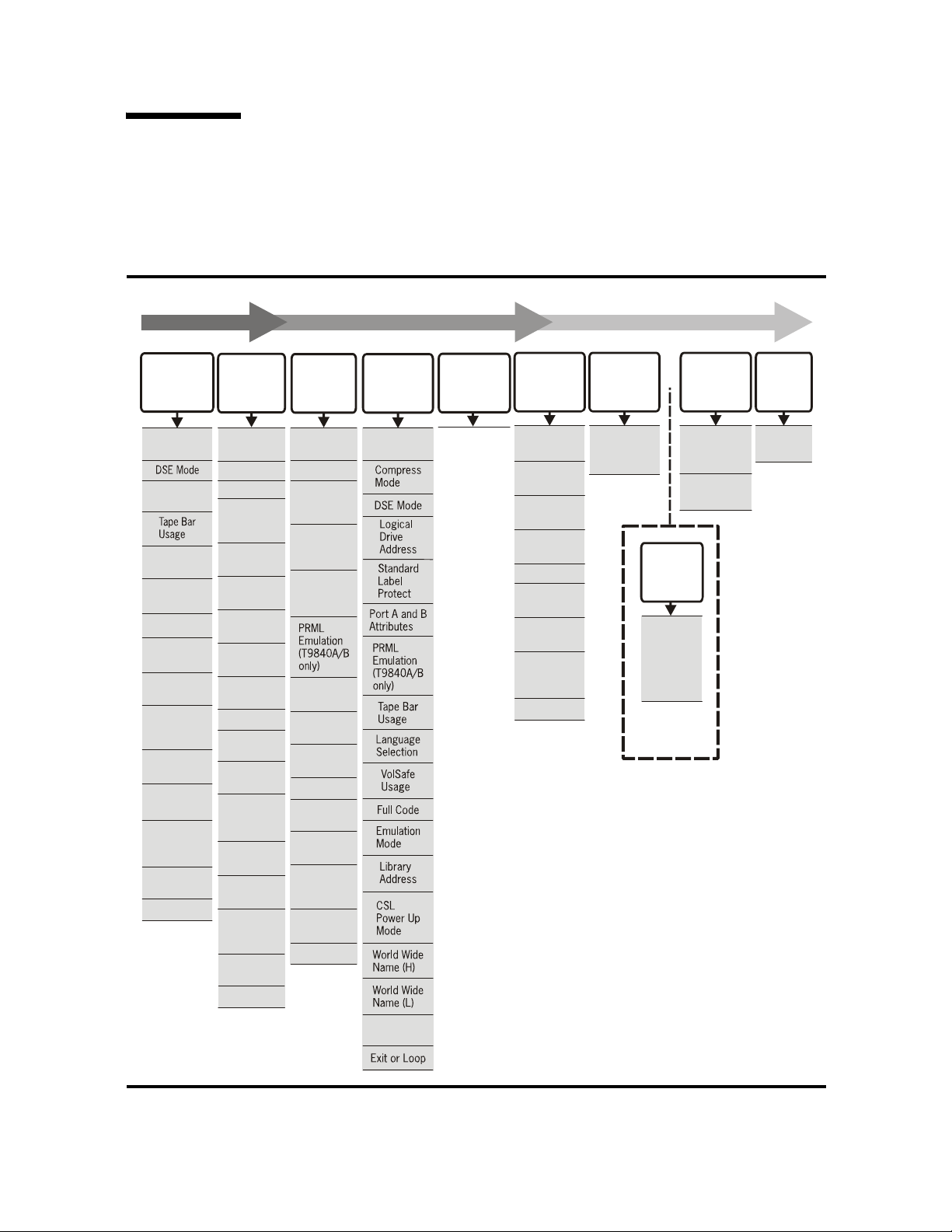
Offline Menus
V
Offline Menus
With the offline menus, the operator can change configuration settings, reformat a data
tape cartridge and build the media information region (MIR) on a tape cartridge.,
FIGURE 3-2 Offline Menus/Interface Menu Tree
Change Drive
Configuration
(Fibre Channel)
Compress
Mode
Port A and B
Attributes
Language
Selection
VolSafe
Usage
Full Code
Emulation
Mode
Library
Address
CSL
Power Up
Mode
World Wide
Name (H)
World Wide
Name (L)
Custom Serial
Number (3590
Mode only)
Save if
Needed
Exit or Loop
Change Drive
Configuration
(SCSI)
Compress
Mode
DSE Mode
SCSI ID
SCSI Target
Negotiation
Mode
SCSI
Speed
SCSI
Width
Tape B a r
Usage
Language
Selection
VolSafe
Usage
Full Code
Emulation
Mode
Library
Address
CSL
Power Up
Mode
World Wide
Name (H)
World Wide
Name (L)
Custom Serial
Number (3590
Mode only)
Save if
Needed
Exit or Loop
ChangeDrive
Configuration
(ESCON)
Compress
Mode
DSE Mode
Logical
Drive
Address
Standard
Label
Protect
Limit Error
Recovery
Process
Tape Ba r
Usage
Language
Selection
VolSafe
Usage
Full Code
Emulation
Mode
Library
Address
CSL
Power Up
Mode
Save if
Needed
Exit or Loop
Change Drive
Configuration
(FICON)
Interface
Selection
ChangeTCP/IP
Configuration
NA T9X40A
See Note
Drive
Operations
IPL from Tape
(Update MC)
Make Dump
Ta pe
Make Code
Ta pe
Make Data
Ta pe
Rebuild MIR
Write/Read
Diagnostic
Servo Head
Diagnostic
Servo Load/
Unload
Diagnostic
Exit or Loop
Note:
The TCP/IP Configuration
submenus are for use by
authorized service
personnel only.
View Drive
Firmware
Level
Drive
Firmware
Release Level
(T9840C & D
FICON ONLY)
View CSL
Firmware
Release Level
iew Drive
Firmware
Level
Stratix and
Excaliber
ASIC
Firmware
Release
Level
View CSL
Firmware
Level
(None =
No CSL)
Exit Menu
Exits Menu
System
Save if
Needed
C53493
62 T9840 User’s Reference Manual • September 2008 Revision YA • 95739
Page 65

Offline Menus
Configuration Changes
You can change configuration settings from the drive offline menu system. You will
continue to use the
You enter the configuration or TCP/IP submenu when you press the Select switch
while the main menu item appears in the display. The first option in the submenu
appears in the display to confirm your selection.
There are three basic types of change mechanisms:
■ Tog gl es
■ Options
■ Val ue s
A toggle is a choice between two values. An example is the DSE mode option where
you must choose between the choices of YES or NO. If YES appears in the display and
you wish the selection to be NO:
1. Press the Select switch - No appears in the display.
2. Press the Menu switch to advance to the next menu item.
Options are similar to toggles, but you must choose among three or more values. An
example is the Compression mode option that has the choices of Yes, No, or OFF.
Menu and Select switches to navigate the offline menu system.
1. Press the Select switch until the desired choice appears in the display.
2. Press the Menu switch to advance to the next menu item.
A value is typically a numeral or a hexadecimal character. Often you will change an
address which consists of one or more characters.
1. Press the Select switch - the left-most character of the value flashes.
2. Press the Select switch to increment the value.
3. Press the Menu switch when the desired value appears in the display - the character
stops flashing.
4. The adjacent character to the right flashes. Repeat steps 1 through 3 to set the proper
value for the second or succeeding character. When you have set all characters, go to
step 5.
5. Press the Menu switch to advance to the next menu item.
Note – If you press the Select switch, the first character in the value sequence flashes,
and you can increment the value.
The last menu item after a change is typically Save/IPL ?. Press the Select switch to
accept the change and start the drive IPL. However, if you press the
display will typically advance to
Exit Menu ?- press Select to exit or Menu to return to
Menu switch, the
the first item in the submenu.
95739 • Revision YA Chapter 3 Menus 63
Page 66
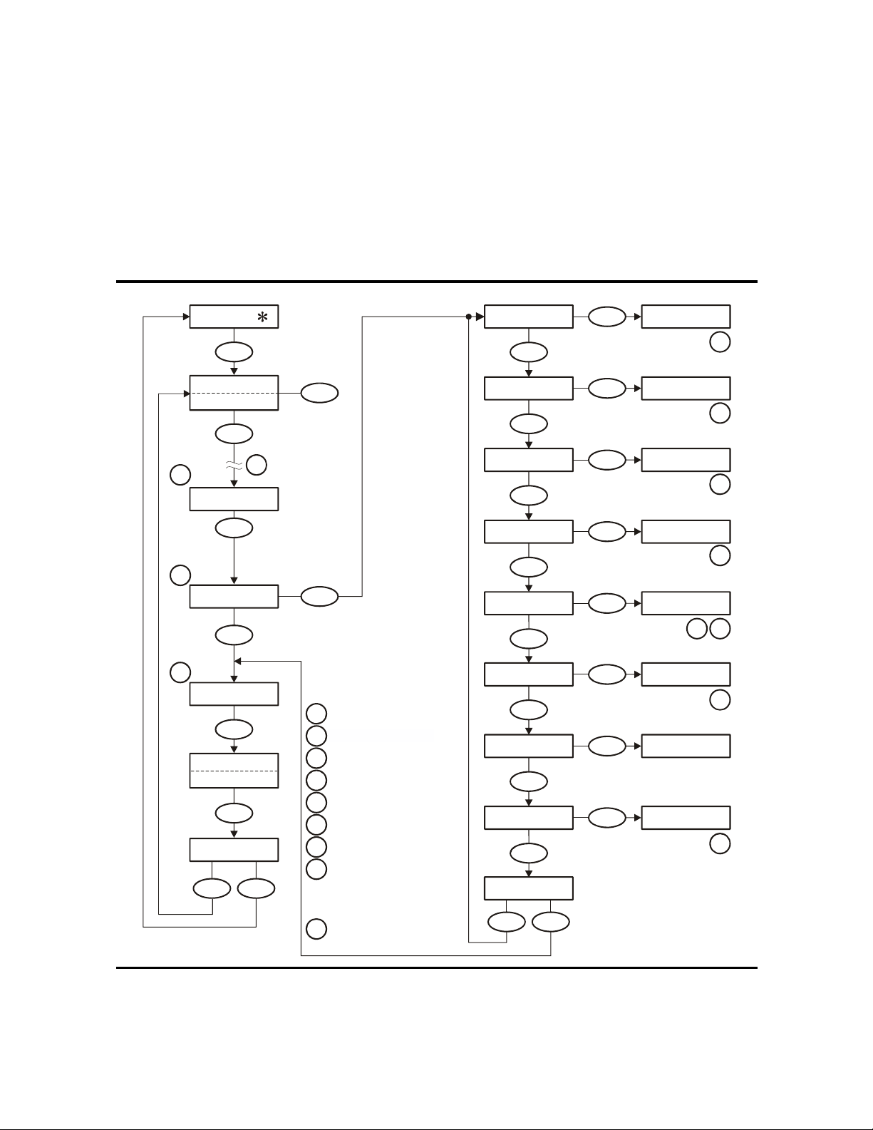
Offline Menus
E
Y
Y
Y
Y
Y
B
Y
W
R
S
Y
Y
Y
Drive Operations Menu
The Drv Menu ? branch of the main menu is the same for Fibre Channel, SCSI, ESCON,
and FICON interfaces.
sub-menus.
Note that the menu items both preceding and following the Drv Menu ? branch vary
with the type of data path interface (see
FIGURE 3-3 Drive Operations Menu Tree
FIGURE 3-3 shows an expansion of the drive operations
FIGURE 3-2 on page 62 for specific menu items).
Menu
Online
Offline
Menu
Menu
No
Menu
No
Menu
XXXXX
Menu
1
No
Select
2
Chng TCP ?
3
Drv Menu ?
4
Rx.yy.zzza
CSL
( /NONE)
x.y.z
Exit Menu?
Menu
No Yes
(Select Offline)
Select
To gg le
Select
Yes
Notes:
See interface Menu Tree.
1
2
T9840B. See Figure 3-6.
NA T9840A
Offline only.
3
Firmware release number.
4
Insert Firmware tape.
5
If
6
Insert Write-Enabled tape.
on a
to
7
Insert tape requiring MIR.
8
into the feed channel.
Insert known good scratch tape.
9
using a CSL to build the MIR
tape, press the start switch
load a tape after inserting
IPL FromTP
Menu
MakeDumpTp
Menu
MakeCodeTp
Menu
MakeDataTp
Menu
uild MIR
Menu
/R Diag
Menu
No
eadCustTP
Menu
rvoLdUnld
Menu
xit Drv ?
Menu
Select
Select
es
No
Select
es
No
Select
es
No
Select
es
No
Select
es
No
Select
es
No
Select
es
No
Select
es
No
es
Ld IPL Tp
5
Ld Dump Tp
6
Ld Code Tp
6
Ld Data Tp
6
Ld Cust Tp
87
LdScrtchTp
9
Ld Cust Tp
LdScrtchTp
9
C53631
64 T9840 User’s Reference Manual • September 2008 Revision YA • 95739
Page 67

CHAPTER
4.
Operator Tasks
This chapter discusses operator tasks primarily for desktop and rack-mounted tape
drives. Most of these tasks rely on the physical operator panel switches, alphanumeric
display, and the drive menu system.
Note – For operator tasks relating to drives within a library, consult the appropriate
library operator guide.
■ Power-on the Drive
■ Power-off the Drive
■ IPL the Drive
■ Write-protect/Enable a Data Cartridge
■ Load a Data Cartridge
■ Unload a Data Cartridge
■ Clean the Drive
■ Place the Drive Online
■ View Drive Configuration
■ View Firmware Release Level
■ Place the Drive Offline
■ Reformat a Cartridge
■ Build MIR
■ Exit the Menu System
You can use the Virtual Operator Panel, version 1.0.12 (or higher), with the T9840D tape
drive to perform many of the operator tasks listed above. The Virtual Operator Panel
provides a graphical user interface to accomplish task functions. See the StorageTek
Virtual Operator Panel Customer User’s Guide (part number 96179) for specific
information.
95739 • Revision YA 67
Page 68

Power-on the Drive
1. Make sure the power cord is connected from the receptacle on the chassis rear panel
2. Make sure that all interface cables are fully seated.
3. Set the power switch on the back of the drive or the rear panel to on (|).
Power-on the Drive
To apply power to the desktop or rack-mount configuration:
to an AC power outlet or power strip.
The drive(s) will power-on and perform an initial program load (IPL).
■ The drive power indicator flashes.
■ Various messages relative to the IPL sequence appear in the operator panel display
window. These messages do not require any action from you.
When the drive successfully completes an IPL:
■ The drive power indicator is steady
■ An asterisk (*) appears in the operator panel display window
Power-off the Drive
To remove power from the desktop and rack-mount configuration:
1. Make sure the tape drive is not in use.
Check for the following elements:
a. There are no active jobs, applications, or programs using this drive.
b. The operator panel activity indicator is steady and not flashing.
c. The display window does not indicate any activity relative to tape movement,
such as reading, writing, or locating.
2. Make sure a data cartridge is not loaded in the tape drive (see “Unload a Data
Cartridge” on page 72, as necessary).
3. Set the power switch on the rear panel to off (O).
68 T9840 User’s Reference Manual • September 2008 Revision YA • 95739
Page 69

IPL the Drive
IPL the Drive
To IPL (initial program load) a drive that is already powered on:
1. Make sure the tape drive is not in use.
Checking for the following elements:
a. There are no active jobs, applications, or programs using this drive.
b. The operator panel activity indicator is steady and not flashing.
c. The display window does not indicate any activity relative to tape movement,
such as reading, writing, or locating.
2. Make sure a data cartridge is not loaded in the tape drive (see “Unload a Data
Cartridge” on page 72, as necessary).
3. Press the operator panel IPL switch.
Once the IPL starts, the following things happen:
■ The drive power indicator flashes
■ The operator panel display window shows various messages relative to the IPL
sequence. These messages do not require any action from you.
When the drive successfully completes an IPL:
■ The drive power indicator is steady
■ An asterisk (*) appears in the operator panel display window
Note – If there is a dump present, the operator panel display window alternates
between the asterisk and the dump message. The dump present indication will stop
when a tape cartridge is loaded.
95739 • Revision YA Chapter 4 Operator Tasks 69
Page 70
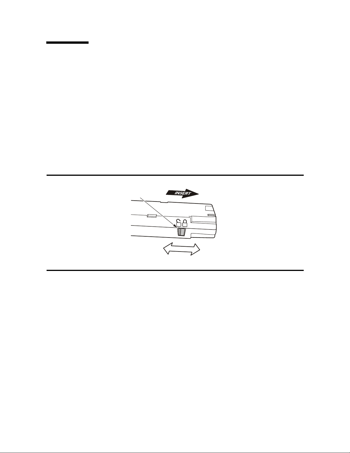
Write-protect/Enable a Data Cartridge
Write-protect/Enable a Data Cartridge
To write-protect or write-enable a data cartridge, move the write-protect switch on the
cartridge to the desired setting.
The write-protect switch is located on the side of the cartridge as shown in FIGURE 4-1.
The switch points to a padlock symbol on the case to indicate the following status:
Locked Write protected. Data can only be read from the data cartridge.
Unlocked Write enabled (unprotected). Data can be read from and
written to the standard data cartridge. With a VolSafe
cartridge, data can be read from the cartridge; and, data can be
appended if the drive VolSafe configuration option is enabled.
FIGURE 4-1 T9840 Data Cartridge Write Protect Switch
WRITE
PROTECT
SWITCH
UNLOCKED
(UNPROTECTED)
LOCKED
(PROTECTED)
C53995
70 T9840 User’s Reference Manual • September 2008 Revision YA • 95739
Page 71

Load a Data Cartridge
Load a Data Cartridge
To load a cartridge into a T9840 tape drive:
Note – A T9840 tape drive accepts only T9840 cartridges.
1. Inspect the cartridge for damage (see “Identify a Damaged Cartridge” on page 95).
2. Look into the drive load/unload slot to make sure there are no obstructions.
3. Hold the cartridge by the finger grips with the hub side down, and insert the
cartridge, carefully, into the tape drive loading slot.
Note – For scratch data cartridges and other data cartridges on which the tape is
written, make sure the write protect switch on the data cartridge is in the unlocked
position (see “Write-protect/Enable a Data Cartridge” on page 70).
4. Push the cartridge into the load slot
Note – For desktop or rack-mounted tape drives, when a cartridge is loaded, the
operator panel display window indicates one of the values in the following table.
Display Meaning
Ready U The cartridge is ready and not file protected (the drive can
read, write, or append data).
Ready F The cartridge is ready and file protected; or a VolSafe
cartridge is loaded, but the drive VolSafe option is
disabled.
Ready A The VolSafe cartridge with the proper density is ready.
Ready H The data cartridge density is higher than the drive is
capable of reading or writing.
Ready L The data cartridge is loaded into a drive that is capable of
writing at a higher density - the drive can read a lower
density cartridge, but cannot append data.
LOAD xxxx The cartridge load was not successful.
95739 • Revision YA Chapter 4 Operator Tasks 71
Page 72

Unload a Data Cartridge
Unload a Data Cartridge
To remove a cartridge from the drive:
Caution – Possible data corruption: Do not push the Unload switch while a data
cartridge is in use. Doing so could cause the tape drive to stop writing and result in
corrupted data on the tape.
To remove cartridges from the drive:
1. Make sure the tape drive is not in use.
Checking for the following elements:
a. There are no active jobs, applications, or programs using this drive.
b. The operator panel activity indicator is steady and not flashing.
c. The display window does not indicate any activity relative to tape movement,
such as reading, writing, or locating.
2. Press the operator panel Unload switch.
An asterisk (*) should appear in the display when the cartridge is unloaded.
Note – If the drive is offline, the asterisk will alternate with Offline.
3. Grasp the cartridge by the finger grips and extract it from the load/unload slot.
4. Set the write protect switch to the locked position, if applicable.
72 T9840 User’s Reference Manual • September 2008 Revision YA • 95739
Page 73

Clean the Drive
Clean the Drive
After the tape drive transports a predetermined length of tape or records a predetermined number of errors, the
drive.
Note – Use the appropriate cleaning cartridge for the drive model (see “Cartridges” on
page 30).
To clean the tape drive:
Caution – Equipment damage: Do not wet-clean the tape drive. Do not clean the tape
drive unless the Clean indicator lights.
1. Make sure the tape drive is not in use before proceeding to Step 2.
Note – If there is a tape loaded in the tape drive, make sure the application or job that
was using that tape drive is no longer running.
Clean indicator lights. It is time to clean the tape
2. Unload any data cartridge in the tape drive.
3. Insert a cleaning cartridge in the tape drive.
Once loaded, the activity light flashes. When the activity and clean indicators turn off,
cleaning is complete and the tape drive unloads the cleaning cartridge.
Note – The tape drive might immediately eject the cleaning cartridge and show the
message Exp ClCart in the front panel display. This indicates that the cleaning
cartridge has been used its maximum number of cleaning cycles. Discard the worn
cleaning cartridge and insert a new cleaning cartridge into the tape drive.
The cleaning cartridge can be used about 100 times before you must discard it.
If CHK xxxx appears in the tape drive’s front panel display, where xxxx is the fault
symptom code (FSC), a cleaning cartridge failure occurred.
Try the procedure again with a different cleaning cartridge. If the problem persists,
contact your service representative.
4. Remove the cleaning cartridge from the tape drive.
95739 • Revision YA Chapter 4 Operator Tasks 73
Page 74

Menu System Tasks
1. Press the operator panel Menu switch until Offline appears in the display window.
2. Press the operator panel Select switch to toggle the drive state.
3. Press the Menu switch until Exit Menu? appears in the display window.
Menu System Tasks
The remaining operator tasks are accomplished by using the drive menu system. Some
tasks can be performed from the offline menu system only.
Place the Drive Online
To change the tape drive state from offline to online:
Note – If you are within a submenu, press the Menu switch until Exit XXX ?
appears in the display window and press the Select switch to enter the main menu.
Online appears in the display window.
4. Press the Select switch to exit the menu system.
5. Bring the tape drive back online to the host.
This is accomplished by:
■ Enterprise: Vary the tape drive online for all host paths to the tape drive by
keying in one of the following commands:
MVS: V <address> online
VM: Vary on, <address>
■ Open Systems: if there is a switch unit installed and the port to this tape drive
was blocked, unblock (enable) that switch port.
View Drive Configuration
To view the current drive configuration settings:
1. Press the operator panel Menu switch to enter the menu system:
■ If Online appears in the tape drive’s front panel, go to Step 2.
■ If Offline appears in the tape drive’s front panel shows, press the Select switch
to toggle the drive state.
Note – It is important that you view configuration settings in the online state, because
you cannot accidently change online settings. To change settings, you must first set the
drive to the offline state.
2. Press the Menu switch until View CFG ? appears in the display window.
74 T9840 User’s Reference Manual • September 2008 Revision YA • 95739
Page 75

Menu System Tasks
3. Press the operator panel Select switch (Yes) to enter the view configuration
submenus.
The first configuration setting appears in the operator panel display window.
4. Press either the Menu or the Select switch to step through the configuration settings.
Note – In the drive online state, the Select switch has the same stepping function as the
Menu switch, except when answering a displayed question.
5. Press either the Menu or Select switch until Exit CFG ? appears in the display
window.
6. Press either the Select switch (Yes) to exit the submenu or the Menu switch (No) to
repeat the view configuration sequence.
7. Press the Menu switch until Exit Menu? appears in the display window.
8. Press either the Select switch (Yes) to exit the menu system or the Menu switch (No) to
return to the online/offline selection menu.
View Firmware Release Level
To view the firmware release level:
1. Press the Menu switch to enter the menu system.
2. Press the Menu switch until a number in the form of Rx.yy.zzzc appears in the
display.
Where:
x is the major revision level
yy is the minor revision level
zzz is the integration level
c is the channel type:
f is Fibre Channel
s is SCSI
e is ESCON/FICON (3490 image)
m is ESCON/FICON (3590 image)
3. Press the Menu switch repeatedly until Exit Menu? appears in the display window.
4. Press either the Select switch to exit the menu system or press the Menu switch to
repeat the Online/Offline selection.
Place the Drive Offline
To change the drive state to offline:
1. Cease all I/O activity from the host.
In mainframe environments, vary all host paths to the tape drive offline by entering
one of the following commands:
■ MVS: V <address> offline
■ VM: Vary off, <address>
95739 • Revision YA Chapter 4 Operator Tasks 75
Page 76

Menu System Tasks
2. Press the operator panel Menu switch.
3. Press the operator panel Select switch to toggle the drive state.
4. Press the Menu switch until Exit Menu? appears in the display window.
5. Press either the Select switch to exit the menu system or the Menu switch to return to
In open systems environments, this is usually done by either:
■ Stopping the job that is using that tape drive
■ Or, in a multi-host setting, by making sure that any job using that tape drive has
been stopped and then blocking (disabling) the switch port to that tape drive, if
there is a switch unit in use.
Online appears in the display window.
Offline appears in the display window to indicate a successful transition to the
offline state.
the first main menu item (use the offline main menu as appropriate, see
“Offline
Menus” on page 62).
Note – If you select Exit Menu? the display alternates between Offline and the
normal message after a cartridge has been loaded as a reminder that the drive is still in
the offline state.
Reformat a Cartridge
You can reformat a data cartridge for new data recording using the offline drive
operations menu. Once a data cartridge is reformatted, old data is no longer accessible
because the reformatting and new data recording overwrites previous data areas.
Note – You cannot reformat a VolSafe data cartridge with the offline drive operations
submenu.
To reformat a cartridge:
1. Press the Menu switch to access the menu system.
a. If the display shows Offline, go to step 2.
b. If the display shows Online, press the Select switch to place the drive offline.
2. Press the Menu switch until Drv Menu ? appears in the display.
3. Press the Select switch to enter the submenu.
4. Press the Menu switch until MakeDataTp appears in the display.
5. Press the Select switch (Ld Data Tp appears in the display).
6. Inspect the cartridge for damage (see “Identify a Damaged Cartridge” on page 95).
7. Load a write-enabled data cartridge in the drive load slot (see “Load a Data
Cartridge” on page 71).
The drive reformats and ejects the data cartridge.
8. Remove the cartridge.
76 T9840 User’s Reference Manual • September 2008 Revision YA • 95739
Page 77

Menu System Tasks
9. Press the Menu switch until Exit Drv ? appears in the display.
10. Press either the Select switch to enter the main menu or the Menu switch to repeat the
drive operations menu.
11. Press the Menu switch until Exit Menu? appears in the display
12. Press either the Select switch to exit the menu system or the Menu switch to repeat
the Online/Offline selection.
Note – It is a best practice to return the drive to the online state. See “Place the Drive
Online” on page 74.
Build MIR
This process rebuilds an MIR from the operator panel.
1. Set the drive to the offline state.
2. Press the Menu switch until Drv Menu? appears in the display window.
3. Press the Select switch (Yes) once.
The first drive utilities submenu appears in the display window.
4. Press the Menu switch until Build MIR appears in the display window.
5. Press the Select switch to begin the MIR rebuilding process.
Ld Cust Tp appears in the display window.
Note – Any loaded cartridge unloads at this time. If present, remove any unloaded
cartridge.
6. Inspect the cartridge for damage (see “Identify a Damaged Cartridge” on page 95).
7. Insert a write-enabled cartridge with a defective MIR (see “Load a Data Cartridge” on
page 71).
The drive rebuilds the MIR and ejects the data cartridge.
Note – Rebuilding the MIR could take up to 40 minutes for a full data cartridge.
8. Remove the cartridge from the drive load/unload slot.
If there are other cartridges for MIR rebuilding, repeat Step 6 and Step 7 for each
cartridge. When the drive has rebuilt all cartridges with defective MIRs, continue with
Step 9.
9. Press the Menu switch once.
Exit Drv? appears in the display window.
10. Press either the Select switch (Yes) to exit the drive utilities submenus or
the Menu switch (No) to repeat the utilities submenu sequence.
11. Press the Menu switch until Exit Drv ? appears in the display.
95739 • Revision YA Chapter 4 Operator Tasks 77
Page 78

Menu System Tasks
12. Press either the Select switch to enter the main menu or the Menu switch to repeat the
13. Press the Menu switch until Exit Menu? appears in the display
14. Press either the Select switch to exit the menu system or the Menu switch to repeat
1. Press the Menu switch repeatedly until Exit Menu? appears in the display window.
drive operations menu.
the Online/Offline selection.
Note – It is a best practice to return the drive to the online state. See “Place the Drive
Online” on page 74.
Exit the Menu System
To exit the menu system:
Note – If you are within a submenu, press the Menu switch until Exit XXX ?
appears in the display window and press the Select switch to enter the main menu.
2. Press the Menu switch to determine the current drive state (Offline or Online
appears in the display).
3. If the present state is offline, press the Select switch (Online appears in the
display)
4. Press the Menu switch repeatedly until Exit Menu? appears in the display.
5. Press the Select switch (an * or Online appears in the display).
78 T9840 User’s Reference Manual • September 2008 Revision YA • 95739
Page 79

CHAPTER
5
Indicators and Messages
This chapter summarizes the operator panel indicator lights and display messages.
Indicators
TABLE 5-1 shows the meaning of the indicators located on the front panel and the
recommended action.
TABLE 5-1 Operator Panel Indicators
Indicators
Meaning Recommended Actionpower activity clean service
Off The drive is powered off. Power on the drive as
required.
Flashing Off The drive is in initial
program load (IPL).
Persistent
Flashing
On Off Normal operation. None.
On Off No tape cartridge is
On On A tape cartridge is loaded. None.
On Flashing The tape is moving. None.
On Off No cleaning is required. None.
On On Cleaning is required. Load the appropriate cleaning
Off The drive failed IPL and
cannot exit the sequence.
loaded.
None.
Power the drive off and on
again. If the problem persists,
contact authorized service
personnel.
Load a tape cartridge as
needed.
cartridge in the drive.
95739 • Revision YA 79
Page 80
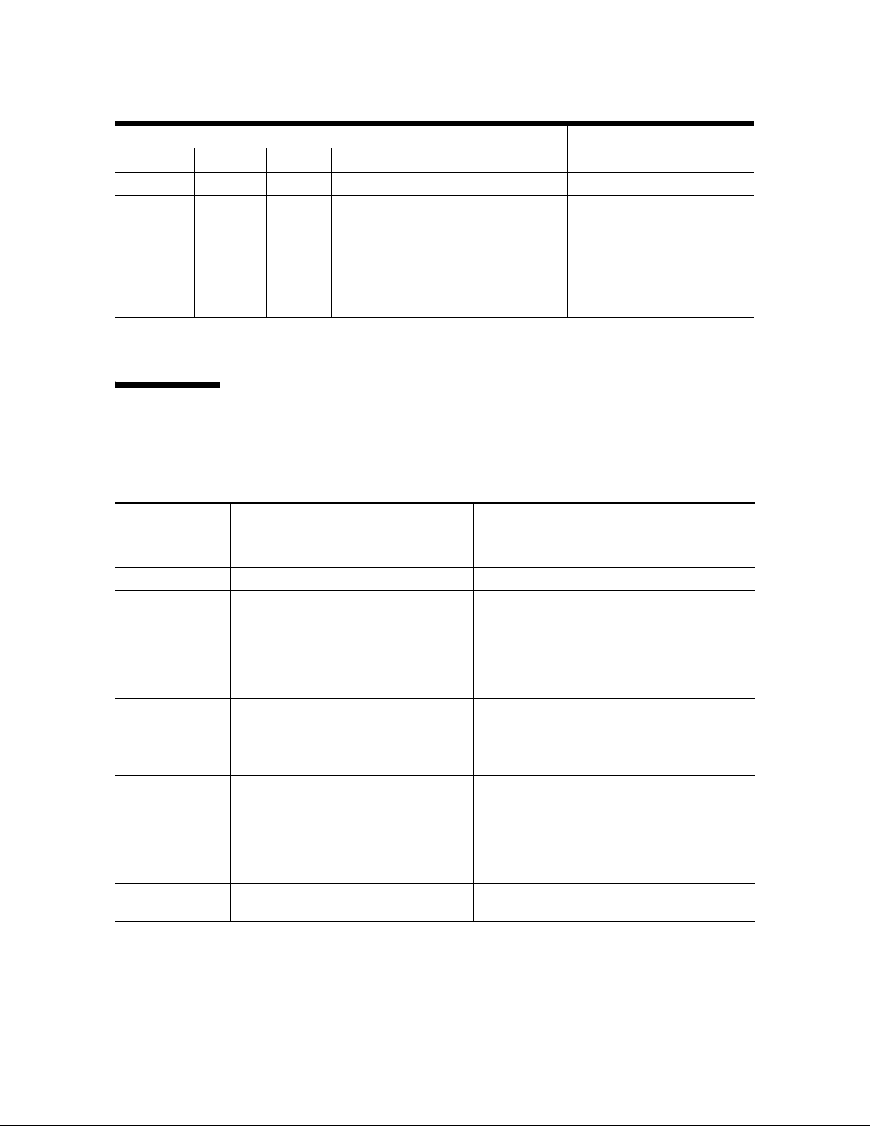
Messages
TABLE 5-1 Operator Panel Indicators (Continued)
Indicators
Meaning Recommended Actionpower activity clean service
On Flashing On Cleaning is proceeding. None.
On On A drive error occurred. Perform an IPL on the drive.
If the problem persists,
contact authorized service
personnel.
On
Flashing An error occurred and
dump data was collected.
Observe the display message.
See x for more information
about the message.
Messages
TABLE 5-2 lists operator panel display messages, meanings, and recommended actions.
TABLE 5-2 Operator Panel Display Messages
Display Meaning Recommended Action
* (asterisk) The tape drive is online but a cartridge
tape is not loaded.
ASIA Diags IPL diagnostics are running. None
Bank n Bad During boot, a section of memory was
found bad.
BldMIRFail Rebuild of Media Information Region
(MIR) unsuccessful.
Note: Code level 1.30.109 and higher
displays CHK XXXX.
Boot Fail The IPL failed. IPL the tape drive again. If the problem persists,
BT Monitor A sequence of switches accessed an
engineering area.
CC Diags IPL diagnostics are running. None
CHK xxxx, where
xxxx is an FSC
Cleaning
(*Cleaning*)
An operational failure occurred; the tape
drive might automatically perform an
IPL depending on the operational mode
of the drive and the specific failure.
A cleaning cartridge is in the tape drive
and is now cleaning.
Load a cartridge tape as required.
IPL the tape drive. If the problem persists,
contact authorized service personnel.
contact authorized service personnel.
IPL the tape drive. If the problem persists,
contact authorized service personnel.
Wait for the IPL to complete and retry the
operation. If the problem persists, contact
authorized service personnel.
See TA BLE 5-3 on page 84 for a list of codes that
are most often caused by an operator error.
None
80 T9840 User’s Reference Manual • September 2008 Revision YA • 95739
Page 81

TABLE 5-2 Operator Panel Display Messages (Continued)
Display Meaning Recommended Action
cnhndnsn
(Hardware
revision level
supported by the
firmware in this
drive)
CodCrFail1 The tape drive cannot write code onto the
CodCrFail2 The tape drive cannot read code from the
CodeUpDate The firmware in the tape drive is being
CodUpFail1 The tape drive cannot read the data
CodUpFail2 The EEPROM failed. Contact authorized service personnel.
CodUpFail3 The tape drive cannot read code from the
CodUpFail4 The data cartridge tape is not a code
DatCrFail1 The tape drive cannot create (reformat or
DmpCrFail1 The tape drive cannot create (reformat or
DmpCrFail2 The tape drive cannot read the format of
DmpWrFail1 The tape drive cannot write diagnostic
DmpWrFail2 There is no diagnostic dump data to
xxxx:Dmp y Alternates with * (an asterisk) after
The tape drive firmware level is
insufficient to control the tape drive
hardware.
data cartridge tape, or the tape drive
cannot position the data cartridge tape.
data cartridge tape.
updated from the host; the operator
panel switches are locked.
cartridge tape, or the tape drive cannot
position the data cartridge tape.
data cartridge tape.
update cartridge tape.
reclaim) a cartridge tape.
reclaim) a diagnostic dump tape.
the data cartridge tape.
data onto the data cartridge tape, or the
tape drive cannot position the data
cartridge tape.
process.
completion of IPL, where xxxx=the FSC
of last dump data collected and Y=
number of uncollected dumps in nonvolatile memory.
Contact authorized service personnel.
Ensure that the tape is write-enabled, or try
another cartridge tape.
Retry the operation, or try another cartridge
tape. If the problem persists, contact authorized
service personnel.
None
Try another cartridge tape.
Retry the operation, or try another cartridge
tape. If the problem persists, contact authorized
service personnel.
Try another code update cartridge tape.
If the problem persists, contact authorized
service personnel.
Ensure that the data cartridge tape is writeenabled, or try to reformat the tape on another
drive. If the problem persists, contact authorized
service personnel.
Ensure that the data cartridge tape is writeenabled. If the problem persists, contact
authorized service personnel.
Retry the operation, or try another cartridge
tape. If the problem persists, contact authorized
service personnel.
Contact authorized service personnel.
Contact authorized service personnel.
Contact authorized service personnel who
accesses the diagnostic data and collects it to
tape or to the host.
Messages
95739 • Revision YA Chapter 5 Indicators and Messages 81
Page 82

Messages
TABLE 5-2 Operator Panel Display Messages (Continued)
Display Meaning Recommended Action
DumpAgain?
alternating with
CHK xxxx, where
xxxx is an FSC.
DumpToHost The dump or event log is being
Exp ClCart The cleaning cartridge is used up. Replace the cleaning cartridge.
Fix CfgErr The checksum does not match after an
Init xxxx.
where xxxx is an
FSC
IPL Pend The IPL switch has been pressed. None
LOAD CC The common controller code is loading;
LOAD ESCON ESCON firmware is loading; IPL is
LOAD FIBRE Fibre Channel firmware is loading; IPL is
LOAD FICON FICON firmware is loading; IPL is
LOAD SERVO The servo code is loading; IPL is
LOAD SCSI SCSI firmware is loading; IPL is
LOAD xxxx,
where xxxx is an
FSC
Loading A cartridge tape is loading. None
Locating The tape drive is doing a high-speed
Memory Err The IPL failed. IPL the tape drive again. If the problem persists,
NTReady A A write-enabled VolSafe data cartridge is
NTReady F A write-protected tape is in the process of
NTReady U A write-enabled tape is in the process of
Offline,
alternating
with *
The tape drive detected the same error
within a minute.
Note: The Service indicator is flashing.
transferred to the host; operator panel
switches are locked.
IPL.
An initialization error occurred. Contact authorized service personnel.
IPL is proceeding.
proceeding.
proceeding.
proceeding.
proceeding.
proceeding.
The load or unload operation failed. If the load failed, insert another cartridge tape. If
seek.
in the process of a manual unload.
a manual unload.
a manual unload.
The tape drive is offline. Perform offline menu operations or exit the
IPL the tape drive. If the problem persists,
contact authorized service personnel.
None
Contact authorized service personnel.
None
None
None
None
None
None
it loads successfully, suspect the original tape. If
another tape fails to load, IPL the tape drive.
If the problem persists, contact your Sun service
representative.
None
contact authorized service personnel.
None
None
None
menu system.
82 T9840 User’s Reference Manual • September 2008 Revision YA • 95739
Page 83

Messages
TABLE 5-2 Operator Panel Display Messages (Continued)
Display Meaning Recommended Action
Online The tape drive is online. None
OnLn Pend The online state is pending completion of
IPL diagnostics.
Power Fail The power supply failed. Contact authorized service personnel.
Reading The tape drive is reading data. None
Ready A The loaded cartridge tape is a VolSafe
cartridge.
Ready F The loaded cartridge tape is write-
protected.
Ready H A loaded high-density data cartridge is
write-enabled by the cartridge writeprotect switch in the unlocked position.
Ready L A loaded low-density data cartridge is
write-enabled by the cartridge writeprotect switch in the unlocked position.
Ready U The loaded cartridge tape is write-
enabled (write-unprotected).
Rewinding The tape drive is rewinding. None
Save Fails The new configuration cannot be saved
because the read-access memory (RAM)
may be defective.
SavingDump A dump is being saved to non-volatile
memory.
Start Init Initialization has started. None
Trapped The IPL process is trapped in a loop. IPL the tape drive again. If the problem persists,
Unloading A cartridge tape is unloading. None
UnWr xxxx,
where xxxx is an
FSC
Write Prot The tape drive attempted to write to a
Writing The tape drive is writing data. None
The Unload switch was pressed during a
write operation. Some data remains
unwritten.
write-protected cartridge tape.
None
None
None
Reload with low-density cartridge or
intentionally over-write from BOT.
Note: High-density data cannot be read by a
T9840A/B drive. T9840D data cannot be read by
a T9840C drive.
Use for read-only jobs or intentionally overwrite from BOT.
Note: Low-density data files can be read, but not
revised by a T9840C/D drive.
None
This message is associated with changing the
tape drive configuration, a task for authorized
service personnel only.
None
contact authorized service personnel.
To write the unwritten data, issue the command:
ESCON Swap in the VM/MVS
environment
Or, Press the Unload switch again; the
unwritten data is lost.
Change the switch on the data cartridge tape to
enable writing.
95739 • Revision YA Chapter 5 Indicators and Messages 83
Page 84

Messages
Potential Operator Recovery Scenarios
The following table contains Fault Symptom Codes (FSCs) that commonly result from
an operator error. The first column in the table lists an operator panel message at the
time of the error event. The description column provides insight into the error
condition from which you should be able to determine a recovery action.
TABLE 5-3 Selected Check Message Meanings
Message Description
CHK 6109 This drive does not contain the key needed to decrypt this tape.
The ID of the missing key can be viewed from this drive using the VOP program.
The ID has also been written to the Operational Key Token (OKT).
Connect the OKT to the Key Management Station (KMS) and view the error log for
error 6109
CHK A33A The user requested a motion operation that requires a tape to be installed, however, a
tape has not been loaded.
CHK A34C The user requested a write operation that requires a tape to be installed, however, a
tape has not been loaded.
CHK A3FB A format override tape write operation failed. The failure may not be serious. Error
recovery was not invoked for the failure. Re-attempting the test may resolve this issue.
CHK A733 The operator or library inserted a write protected tape into the drive while in a menu
selected create tape mode. If the write protect switch on the cartridge is moved to the
unlocked position, operation will work.
CHK A749 A high densitry tape was attempted to be read on a drive only capable of reading
lower density tapes. Retry with a low density tape.
CHK A74E A high density tape was loaded on a low density drive, or a low density tape was
loaded on a high density drive. In either case, the drive cannot write to the tape.
The MIR cannot be written on the tape during the unload process so there is no point
in running the build MIR function.
If it is a high density tape, rebuild the MIR on a high density drive.
If it is a low density tape, rebuild the MIR on a low denisty drive.
84 T9840 User’s Reference Manual • September 2008 Revision YA • 95739
Page 85

Translated Messages
TABLE 5-4 lists operator panel display messages that are translated when the drive
configuration Language option is set to something other than English.
TABLE 5-4 Translated Display Messages
English Espanol Francais Italiano Deutsch
*CLEANING* *LIMPIEZA* *NETTOYAGE *PULIZIA* *REINIGEN*
CHK XXXX ERR XXXX ERR XXXX ERR XXXX PRUEF XXXX
*ERASING* *BORRANDO* EFFACEMENT *CANCELLA* *LOESCHEN*
Locating Localizar Recherche Ricerca Suchen
LOAD XXXX CARGA XXXX CHARG XXXX CARIC XXXX LADEN XXXX
Loading Cargando Chargement Carico Laden
NT Ready A No Listo A NPret A No Prnt A N Bereit A
NT Ready F No Listo F NPret F No Prnt F N Bereit F
NT Ready U No Listo U NPret U No Prnt U N Bereit U
*Overtemp* *Caliente* *Overtemp* *Temperat* * Heiss *
Processing Procesar Traitement Processo Verarbeitn
Reading Leer Lecture Lettura Lesen
Ready A Listo A Pret A Pronto A Bereit A
Ready F Listo F Pret F Pronto F Bereit F
Ready H Listo H Pret H Pronto H Bereit H
Ready L Listo L Pret L Pronto L Bereit L
Ready U Listo U Pret U Pronto U Bereit U
Rewinding Rebobinar Rebobinage Riavvolgi Spulen
Unloading Descarga Dechargemt Scarico Entladen
Writing Excritura Ecriture Scrittura Schreiben
Messages
95739 • Revision YA Chapter 5 Indicators and Messages 85
Page 86

Messages
86 T9840 User’s Reference Manual • September 2008 Revision YA • 95739
Page 87

APPENDIX
A
Specifications
This appendix lists the physical, power, and performance specifications for the T9840
tape drive plus the environmental requirements for the drive and data cartridges.
Physical Specifications
This section lists the physical specifications for T9840 tape drives in three
configurations: desktop, rack mount, and library attached.
Tape Drive Only
TABLE A-1 lists the T9840 tape drive physical specifications.
TABLE A-1 T9840 Tape Drive Physical Specifications
Measurement Specification
Width 146 mm (5.75 in.)
Depth 381 mm (15 in.)
Height 82.5 mm (3.25 in.)
95739 • Revision YA 87
Page 88

Physical Specifications
Desktop Configuration
The T9840 desktop configuration is a single enclosed assembly.
TABLE A-2 T9840 Tape Drive Desktop Physical Specifications
Characteristic Manual-Load Drive Cartridge Scratch Loader
Chassis dimensions
230 mm (9.1 in.) wide
160 mm (6.5 in.) high
483 mm (19 in.) deep
Wei gh t: 9.3 kg (20.5 lb) 23 kg (50 lb)
1. Plus 76 mm (3 in.) for cables
483 mm (19 in.) wide
197 mm (7.7 in.) high
1
630 mm (24.8 in.) deep
Rack-Mount Configuration
TABLE A-3 lists the physical specifications for the T9840 rack-mount configuration.
TABLE A-3 T9840 Tape Drive Rack-mount Physical Specifications
Characteristic Va lue
Chassis dimensions 483 mm (19 in.) wide
177 mm (7.0 in.) high
630 mm (24.8 in.) deep plus 76 mm (3 in.) for cables
Wei gh t:
single drive
dual drive
Cartridge Scratch Loader 18 kg (39 lb)
14.1 kg (32 lb)
20.4 kg (45 lb)
1
Library-attached Configuration
TABLE A-4 lists the weights of the library tape drives and accessories (including trays,
power supplies, and cables).
TABLE A-4 T9840 Tape Drive Weights (Library-attached)
Library Drive and Accessory Weights
9310/9740/L5500 7.30 kg (16.1 lb)
L180/L700/L1400 7.39 kg (16.3 lb)
SL8500 8.85 kg (19.5 lb)
The T9840 Tape Drive library-attached configuration trays fit inside the:
■ StorageTek L180/L700/L1400 libraries
■ StorageTek SL8500 Modular Library System
■ 9741 drive cabinet that attaches to StorageTek 9310 and 9740 libraries
■ 9741E drive cabinet that attaches to StorageTek 9310, 9740, and L5500 libraries
88 T9840 User’s Reference Manual • September 2008 Revision YA • 95739
Page 89

Refer to the appropriate library System Assurance Guide for the physical dimensions
and weights of the library and frame.
Power Specifications
The power specifications for the T9840 tape drive are listed in the following table.
TABLE A-5 T9840 Tape Drive Power Specifications
Characteristic Valu e
Input voltage 100 to 240 VAC
Input frequency 50 to 60 Hz
Power consumption T9840D
■ 61.7 W - write
■ 43 W - Idle with tape loaded
■ 35 W - Idle no tape loaded
SL8500 Power dissipation 345 Btu/hr
Power Specifications
T9840C
■ 65 W - write
■ 45 W - Idle with tape loaded
■ 38 W - Idle no tape loaded
95739 • Revision YA Appendix A Specifications 89
Page 90

Environmental Requirements
Environmental Requirements
This section lists the environmental requirements for the tape drive, power supply, and
tape cartridge.
Tape Drive and Power Supply
This section lists the environmental requirements for the tape drive and the power
supply.
TABLE A-6 T9840 Tape Drive and Power Supply Environmental Requirements
Description Range
Te mp e r at u r e
Operating
Shipping
Storing
Relative Humidity, (non-condensing)
Operating
Shipping
Storing
Wet B u l b M a x i m u m
Operating
Shipping
Storing
15° to 32°C (59° to 90°F)
-40° to 60°C (-40° to 140°F)
10° to 40°C (50° to 104°F)
20% to 80%
10% to 95%
10% to 95%
29°C (84°F)
35°C (95°F)
35°C (95°F)
Altitude
Operating
Shipping
Storing
Air Flow Requirement (Operating Heat Output)
Drive and power supply operating
90 T9840 User’s Reference Manual • September 2008 Revision YA • 95739
26°C (79°F) 3.05 km (10,000 feet)
26°C (79°F) 15.2 km (50,000 feet)
26°C (79°F) 3.05 km (10,000 feet)
73.2 Calories/hr (290.2 Btu/hr)
Page 91

Environmental Requirements
Tape Cartridge
TABLE A-7 lists the T9840 tape cartridge environmental requirements.
TABLE A-7 T9840 Tape Cartridge Environmental Requirements
Temperatu re
Operating
Storage (up to four weeks) 5° to 32°C (41° to 90°F)
Storage (archival) 18° to 26°C (65° to 79°F)
Shipping (unrecorded)
Shipping (recorded)
Relative Humidity, Non-condensing
Operating
Storage (up to four weeks) 5% to 80%
Storage (archival) 40% to 60%
Shipping (unrecorded)
Shipping (recorded)
Wet Bulb Maximum
Operating
Storage (nonarchive) 26°C (79°F)
Storage (archival) 26°C (79°F)
Shipping (unrecorded)
Shipping (recorded)
1. The acclimation time before use is 24 hours.
2. The shipping environment must not exceed the limit of the storage environment, archive or nonarchive, for longer than
10 days.
1
2
2
1
2
2
1
2
2
15° to 32°C (59° to 90°F)
-23° to 49°C (-10° to 120°F)
4° to 40°C (40° to 104°F)
20% to 80%
5% to 80%
5% to 80%
26°C (79°F)
26°C (79°F)
26°C (79°F)
95739 • Revision YA Appendix A Specifications 91
Page 92

Performance Specifications
Performance Specifications
This section describes the T9840 Tape Drive and Tape Cartridge performance.
Tape Drive
TABLE A-8 lists the performance specifications of the T9840 tape drive.
TABLE A-8 T9840 Tape Drive Performance Specifications
Characteristic
Capacity and Performance
Capacity, native
Data buffer size
tape speed, read/write
Performance, native (head-to-tape
uncompressed
compressed (maximum)
Burst (FC & FICON)
Burst (ESCON)
Interface data
Fibre Channel
Ultra SCSI (HVD)
ESCON
FICON
Access times
Tape load and thread to ready
File access, first (average)
Rewind (maximum/average)
Unload
Reliability
Mean time between failure (MTBF)
Power on @ 100% duty cycle
Tape load @ 10/day (100k loads)
Tape path motion (TPM) @ 70%
duty cycle
Head life @ 70% TPM duty cycle
Uncorrected bit error rate
Undetected bit error rate
1. VR2 is a trademark of Overland Storage.
VR2 technology is used to achieve T9840C and T9840D capacity.
2. Fibre Channel (FC) write and 55 MB/s FICON write
T9840A T9840B T9840C T9840D
20 GB
8 MB
2 m/s
10 MB/s
35 MB/s
100 MB/s
17 MB/s
1 Gb
40 MB/s
17 MB/s
N/A
7 sec
8 sec
16/8 sec
8 sec
290,000 hr
240,000 hr
216,000 hr
5 years
-18
1 x 10
-33
1 x 10
20 GB
32 MB
4 m/s
19 MB/s
60 MB/s
200 MB/s
17 MB/s
2 Gb
40 MB/s
17 MB/s
2 Gb
7 sec
8 sec
16/8 sec
8 sec
290,000 hr
240,000 hr
216,000 hr
5 years
1 x 10
1 x 10
-18
-33
Value
40 GB
64 MB
3.295 m/s
30 MB/s
60 MB/s
200 MB/s
17 MB/s
2 Gb
N/A
17 MB/s
2 Gb
6.5 sec
8 sec
16/8 sec
11.5 sec
290,000 hr
240,000 hr
216,000 hr
5 years
1 x 10
1 x 10
1
-18
-33
1
75 GB
64 MB
3.4 m/s
30 MB/s
60 MB/s
200 MB/s
17 MB/s
2 Gb
N/A
17 MB/s
2 Gb
8.5 sec
8 sec
16/8 sec
12.5 sec
290,000 hr
240,000 hr
216,000 hr
5 years
-18
1 x 10
-33
1 x 10
2
92 T9840 User’s Reference Manual • September 2008 Revision YA • 95739
Page 93

Tape Cartridge
TABLE A-9 lists the physical and performance specifications for the T9840 data cartridge.
The cleaning cartridges have the same physical specifications.
TABLE A-9 T9840 Data Cartridge Physical and Performance Specifications
Characteristic Val ue
Cartridge physical data
Drive compatibility
Form factor
Width
Length
Height
Wei gh t
Drop strength
Tape media data
Capacity, native (uncompressed)
Tr ac ks
Track following servo
Formulation
Physical thickness
Physical length
Recordable length (including MIR)
Reliability
Archival life
Short-length durability
Long-life durability
Load/unloads
Uncorrected bit error rate
Permanent errors
1. VR2 is a trademark of Overland Storage.
VR2 technology is used to achieve T9840C and T9840D capacity.
T9840A, T9840B, T9840C, T9840D
1/2 in. cartridge, 3490/3490E
10.9 cm (4.29 in.)
12.5 cm (4.92 in.)
2.54 cm (1.0 in.)
262 g (9.17 oz)
1.0 m (39.4 in.)
20 GB (T9840A, T9840B)
40 GB1 (T9840C))
75 GB1 (T9840D)
288 (T9840A, T9840B, T9840C) 576 (T9840D)
Factory pre-recorded
Advanced metal particle (AMP)
9 microns
271 m (889 ft)
251 m (823 ft)
15-30 years
80,000 write/read passes minimum
6,500 write/read passes minimum
10,000 minimum
-18
1 x 10
Zero
Performance Specifications
95739 • Revision YA Appendix A Specifications 93
Page 94

Performance Specifications
94 T9840 User’s Reference Manual • September 2008 Revision YA • 95739
Page 95

APPENDIX
B
Cartridge Care
9840 cartridges require care to ensure proper operation and longevity.
Handling
Caution – Tape cartridge damage or data loss: Handle tape cartridges properly.
Follow these guidelines to handle tape cartridges properly:
■ Never open a data cartridge or touch the tape.
■ Never carry data cartridges loosely in a container.
■ Never expose the tape or cartridges to direct sunlight or moisture.
■ Never expose a recorded data cartridge to magnetic fields.
■ Always maintain a clean operating, working, and storage environment.
Storing
Always store tape cartridges in an environment with the specified range of temperature
and humidity found in
follow these recommendations:
■ Never take data cartridges out of their protective wrapping until they are needed.
Always use the tear string, not a sharp instrument, to remove the wrapping.
■ Store data cartridges in a dirt-free environment that, if possible, duplicates the
conditions of the data processing center.
■ Before using data cartridges that have been in tape storage, acclimate the cartridges to
the operating environment for at least 24 hours.
“Tape Cartridge” on page 91. When storing tape cartridges,
Identify a Damaged Cartridge
Caution – Equipment damage: Do not load a damaged cartridge.
Before loading a cartridge into a drive, look for the following problems:
■ A cracked or broken case
■ A dirty case (see “Cleaning” on page 96)
95739 • Revision YA 95
Page 96

■ A missing or broken access door
■ A damaged file-protect switch
■ Liquid in the cartridge
■ A loose label (replace or remove the label)
■ Any other obvious damage
Cleaning
Wipe all dust, dirt, and moisture from the cartridge case with a lint-free cloth.
Shipping
Caution – Data cartridge damage: Ship data cartridges properly.
If you must ship tape cartridges, especially if they are for remote system backup,
remote database duplication, or disaster recovery, follow these guidelines:
■ Save the original factory packaging. Use it, or the equivalent, to package tape
cartridges.
■ Wrap the tape cartridges in plastic to block moisture and contamination from
entering the tape cartridges.
■ Pad the tape cartridges on all sides.
■ Fill voids in the packaging with padding equivalent to the original padding, if you
are using factory packaging to ship fewer tape cartridges than the packaging
originally held, or if you are using other packaging.
■ Label the outside of the shipping carton clearly with text or accepted symbols that
indicate:
■ Do not expose to magnetic fields
■ Do not expose to moisture
■ This end up
■ Fragile
96 T9840 User’s Reference Manual • September 2008 Revision YA • 95739
Page 97

Glossary
This glossary defines terms and abbreviations in this publication.
Some of the definitions are taken from other glossaries. The letters in the parentheses
that follow some definitions indicate the source of the definition:
(A) The American National Standard Dictionary for Information Systems, ANSI X3.172-1990,
copyright 1990 by the American National Standards Institute (ANSI).
(E) The ANSI/Electronic Industries Association (EIA) Standard-440-A, Fiber Optic
Terminology.
(I) The Information Technology Vocabulary, developed by Subcommittee 1, Joint Technical
Committee 1, of the International Organization for Standardization and International
Electro-technical Commission (ISO/IEC/JTC1/SC1).
(IBM) The IBM Dictionary of Computing, copyright 1994 by IBM.
(T) Draft international standards committee drafts, and working papers being
developed by the ISO/IEC/JTC1/SC1.
A
access time The time interval between the instant at which a call for data is initialized and
the instant at which the delivery of data is completed. (T)
address A character or group of characters that identifies a register, a particular part of
storage, or some other data source or destination. (A)
alphanumeric A character or group of characters that identifies a register, a particular part of
storage, or some other data source or destination. (A).
B
beginning-of-tape (BOT) The location on a tape where written data begins.
95739 • Revision YA 97
Page 98

block A collection of contiguous records recorded as a unit. Interblock gaps separate
blocks, and each block can contain one or more records.
buffer A routine or storage that compensates for a difference in the rate of data flow, or
the time of occurrence of events when transferring data from one device to
another.
burst In data communication, a sequence of signals counted as one unit in accordance
with a specific criterion or measure. (A)
C
capacity Total amount of User Data stored on one data cartridge in 8-bit bytes.
Synonymous with “User Capacity” or “Native Capacity”. This is the capacity that
the user sees after the ECC/Format/ERP and other overhead has been assessed
(no compression).
capacity, raw Total amount of data stored on one data cartridge in 8-bit bytes before any
ECC/Format/ERP and other overhead has been assessed (no compression).
capacity, user Total amount of data stored on one data cartridge in 8-bit bytes that is sent by
the host computer. This is the capacity that the user sees after the
ECC/Format/ERP and other overhead has been assessed (no compression).
cartridge A storage device that consists of magnetic tape on a supply reel in a protective
housing.
cartridge scratch loader A device that attaches to a tape drive to automatically load and unload tape
cartridges into and out of the drive.
CC See cleaning cartridge
cleaning cartridge A data cartridge that contains special material to clean the tape path in a
transport or drive.
compress To save space by eliminating gaps, empty fields, redundancy, or unnecessary
data to shorten the length of records or files. (IBM)
condition One of a set of specified values that a data item can assume. (IBM)
conditioning time The amount of time to prepare a tape cartridge for use in a T9840 Tape Drive.
configuration The manner in which the hardware and software of an information processing
system is organized and interconnected. (T)
connector An electrical or optical part that joins two or more other parts.
D
data error rate The number of errors that occur per a measurable amount of data on a tape.
data rate The speed of a data transfer process, usually expressed in bits per second or
bytes per second. (IBM)
98 T9840 User’s Reference Manual • September 2008 Revision YA • 95739
Page 99

Data Security Erase
(DSE) A random binary pattern, over-writing existing data, from the point of an
data tape A data cartridge formatted for use as a regular data tape for the system in which
data tracks The regions of recorded tape containing user data formed as discreet
diagnostics Pertaining to the detection and isolation of errors in programs and faults in
drive A drive controls the movement of the tape and records or reads the data on the
dump To copy the contents of all or part of storage to collect error information.
dynamic host
configuration protocol
(DHCP)
E
“Erase” command to the End of Tape point.
it is used.
longitudinal “tracks” (similar to railroad tracks).
equipment.
tape as desired by the customer.
An IP protocol that a host uses to obtain all necessary configuration
information, including an IP address.
emulation The use of programming techniques and special machine features to permit a
computing system to execute programs written for another system. (IBM)
encryption The translation of data into a secret code. Encryption is one of the most effective
ways to achieve data security. To read an encrypted file, you must have access to
a special key or password that enables you to decipher it.
enterprise A representation of the goals, organizational structure, business processes, and
information resources and requirements of an enterprise. (IBM)
Enterprise Systems
Connection (ESCON) A set of IBM products and services that provide a dynamically-connected
environment within an enterprise. (IBM)
environmental
requirement
ESCON See Enterprise Systems Connection.
ESCON channel A channel having an Enterprise Systems Connection channel-to- control-unit
Any of the physical conditions required for the protection and proper operation
of a functional unit; the requirement is usually specified as a nominal value and
a tolerance range. For a device, there may be more than one set of
environmental requirements; for example, one set for transport, another for
storage, and another for operation. (T) (A)
EOT End of tape.
error A discrepancy between a computed, observed, or measured value or condition
and the true, specified, or theoretically correct value or condition. (I) (A)
I/O interface that uses optical cables as a transmission medium.
ESD Electrostatic Discharge.
95739 • Revision YA Glossary 99
Page 100

F
fault symptom code
(FSC) A four-character hexadecimal code generated in response to an error to help
isolate failures within the device. Some FSCs are for information purposes only.
FC See Fibre Channel.
fiber optics The branch of optical technology concerned with the transmission of radiant
power through fibers made of transparent materials such as glass, fused silica,
and plastic. (E)
fiber-optic cable A cable made of ultrathin glass or silica fibers which can transmit data using
pulses of laser light. Fiber-optic cables have several advantages over copper
cables: they have much less signal loss; they allow information to be transmitted
at higher speeds and over longer distances; they are not affected by external
electrical noise; and they are better for transmissions which require security.
Fibre Channel The National Committee for Information Te chnol ogy St andard s standard that
defines an ultrahigh-speed, content-independent, multilevel data transmission
interface that supports multiple protocols simultaneously. Fibre Channel
supports connectivity to millions of devices over copper and/or fiber-optic
physical media and provides the best characteristics of both networks and
channels over diverse topologies.
fibre connection
(FICON) An ESA/390 and zSeries computer peripheral interface. The I/O interface uses
ESA/390 and zSeries FICON protocols (FC-FS and FC-SB-2) over a Fibre
Channel serial interface that configures units attached to a FICON-supported
Fibre Channel communications fabric.
FICON channel A channel having a Fibre Channel connection (FICON) channel-to-control-unit
I/O interface that uses optical cables as a transmission medium. May operate in
either FC or FCV mode.
file-protect To prevent the erasure or overwriting of data stored on data cartridges. See also
write-protect switch.
firmware An ordered set of instructions and data stored in a way that is functionally
independent of main storage; for example, microprograms stored in ROM. (T)
FRU Field replaceable unit.
FSC Fault symptom code.
FTP File Transfer Protocol.
G
Gb Gigabit, equal to 109 bits.
Gbps Gigabits per second.
gigabyte (GB) One X 230 bytes (binary), or 1 X 10⁹ (decimal).
100 T9840 User’s Reference Manual • September 2008 Revision YA • 95739
 Loading...