

Page 1

Sun StorageTek™4 Gb FC NEM
20-Port Host Bus Adapter
User’s Guide
For HBA Model SG-XPCIE20FC-NEM-Z
Sun Microsystems, Inc.
www.sun.com
Part No. 819-7929-11
May 2007, Revision A
Submit comments about this document at: http://www.sun.com/hwdocs/feedback
Page 2

Copyright 2007Sun Microsystems,Inc., 4150Network Circle, SantaClara, California95054, U.S.A.All rightsreserved.
Sun Microsystems,Inc. hasintellectual property rightsrelating totechnology thatis describedin thisdocument. Inparticular,and without
limitation, theseintellectual propertyrights mayinclude oneor more ofthe U.S.patents listedat http://www.sun.com/patents andone or
more additionalpatents orpending patentapplications inthe U.S.and inother countries.
This documentand theproduct towhich itpertains are distributedunder licensesrestricting theiruse, copying,distribution, and
decompilation. Nopart ofthe productor ofthis documentmay bereproducedin anyform byany meanswithout priorwritten authorizationof
Sun andits licensors,if any.
Third-party software, includingfont technology, is copyrighted and licensed from Sunsuppliers.
Parts ofthe productmay bederived from BerkeleyBSD systems,licensed fromthe Universityof California.UNIX isa registered trademarkin
the U.S.and inother countries,exclusively licensedthrough X/OpenCompany, Ltd.
Sun, SunMicrosystems, theSun logo,Java, AnswerBook2,docs.sun.com, StorEdge,Java, SunBlade, SunVTS,StorageTek, FlexLine,and Solaris
are trademarksor registered trademarksof SunMicrosystems, Inc.in theU.S. andin othercountries.
All SPARC trademarks areused underlicense andare trademarksor registered trademarksof SPARC International,Inc. inthe U.S.and inother
countries. Productsbearing SPARCtrademarks arebased uponan architecture developedby SunMicrosystems, Inc.
The OPENLOOK andSun™ GraphicalUser Interfacewas developedby SunMicrosystems, Inc.for itsusers andlicensees. Sunacknowledges
the pioneeringefforts ofXerox in researchingand developingthe conceptof visualor graphicaluser interfacesfor thecomputer industry.Sun
holds anon-exclusive licensefrom Xerox tothe XeroxGraphical UserInterface, whichlicense alsocovers Sun’slicensees whoimplement OPEN
LOOK GUIsand otherwisecomply withSun’s writtenlicense agreements.
U.S. GovernmentRights—Commercial use.Government usersare subject to the Sun Microsystems, Inc.standard licenseagreement and
applicable provisionsof theFAR and its supplements.
DOCUMENTATION IS PROVIDED "AS IS" AND ALL EXPRESS OR IMPLIED CONDITIONS, REPRESENTATIONS AND WARRANTIES,
INCLUDING ANYIMPLIED WARRANTY OFMERCHANTABILITY,FITNESS FOR A PARTICULAR PURPOSEOR NON-INFRINGEMENT,
ARE DISCLAIMED, EXCEPT TO THE EXTENT THAT SUCH DISCLAIMERS ARE HELD TO BE LEGALLY INVALID.
Copyright 2007Sun Microsystems,Inc., 4150Network Circle, SantaClara, Californie95054, États-Unis.Tousdroits réservés.
Sun Microsystems,Inc. possèdeles droits depropriété intellectuelsrelatifs àla technologiedécrite dansce document.En particulier, et sans
limitation, cesdroits depropriété intellectuels peuvent inclure unou plusieursdes brevetsaméricains listéssur lesite
http://www.sun.com/patents, un ou les plusieurs brevetssupplémentaires ainsique lesdemandes debrevet en attente aux les États-Unis et
dans d’autrespays.
Ce documentet leproduit auquelil serapporte sontprotégés par un copyright etdistribués souslicences, celles-cien restreignentl’utilisation,
la copie,la distribution,et ladécompilation. Aucunepartie dece produitou documentne peutêtrereproduite sousaucune forme,par quelque
moyen quece soit,sans l’autorisationpréalable etécrite deSun etde sesbailleurs delicence, s’ily ena.
Tout logiciel tiers, sa technologie relativeaux policesde caractères,comprise, estprotégé par un copyright et licencié par des fournisseurs de
Sun.
Des partiesde ceproduit peuventdériver dessystèmes BerkeleyBSD licenciéspar l’Universitéde Californie.UNIX estune marque déposée
aux États-Uniset dansd’autres pays,licenciée exclusivementpar X/OpenCompany, Ltd.
Sun, SunMicrosystems, lelogo Sun,Java, AnswerBook2,docs.sun.com, StorEdge,Java, SunBlade, SunVTS,StorageTek, FlexLine,et Solaris
sont desmarques defabrique oudes marques déposéesde SunMicrosystems, Inc.aux États-Uniset dansd’autres pays.
Toutes les marques SPARC sontutilisées souslicence etsont desmarquesde fabriqueou desmarques déposéesde SPARC International, Inc.
aux États-Uniset dansd’autres pays.Les produits portantles marquesSPARCsont basés sur une architecturedéveloppée parSun
Microsystems, Inc.
L’interfaceutilisateur graphiqueOPEN LOOKet Sun™a étédéveloppée parSun Microsystems, Inc. pour ses utilisateurs et licenciés. Sun
reconnaît lesefforts de pionniers de Xeroxdans larecherche et le développement du concept des interfaces utilisateur visuelles ou graphiques
pour l’industrieinformatique. Sundétient unelicense nonexclusive deXerox surl’interface utilisateurgraphique Xerox, cettelicence couvrant
également leslicenciés deSun implémentantles interfacesutilisateur graphiquesOPEN LOOKet seconforment enoutre auxlicences écritesde
Sun.
LA DOCUMENTATION EST FOURNIE "EN L’ÉTAT" ET TOUTES AUTRES CONDITIONS, DÉCLARATIONS ET GARANTIES EXPRESSES
OU TACITES SONT FORMELLEMENT EXCLUES DANS LA LIMITE DE LA LOI APPLICABLE, Y COMPRIS NOTAMMENT TOUTE
GARANTIE IMPLICITE RELATIVE À LA QUALITÉ MARCHANDE, À L’APTITUDE À UNE UTILISATION PARTICULIÈRE OU À
L’ABSENCE DE CONTREFAÇON.
Please
Recycle
Page 3

Contents
Preface vii
1. Network Express Module Overview 1
NEM Features and Specifications 1
ID Chip Feature 3
Operating System Requirements 4
System Interoperability 4
Host Platform Support 5
Storage System Support 5
Fibre Channel Switch Support 6
2. Hardware Installation and Removal 7
Observing ESD and Handling Precautions 8
Installing the NEM 8
▼ To Install the NEM 9
▼ To Connect the Optical Cables 11
Configuring the NEM For Hot-Plug Operation 14
Using the ILOM Web Interface 14
Using the ILOM Command-Line Interface 15
Verifying a Hot-Insert Operation 15
iii
Page 4

Using the ILOM Web Interface 16
Using the ILOM CLI 16
▼ To Verify NEM Status 16
Replacing a NEM 18
▼ To Install the ID Chip Patch 18
▼ To Remove a NEM 18
▼ To Replace the ID Chip 19
3. HBA Software Installation 21
Driver Software for the Solaris OS 21
Solaris Diagnostic Support 21
Driver Software for Linux OSs 22
Red Hat Enterprise Linux 22
Novell SUSE Linux Enterprise Server 22
▼ To Update the Driver 22
▼ To Install SLES9-SP3 to FC Disk 23
▼ To Build the Linux 2.6 Driver 23
Driver Software for Windows 2003 OS 24
▼ To Install Windows OS Driver and Application Kits 24
Configuration and Diagnostic Utilities 24
4. Release Notes 27
Using the NEM With Sun StorEdge 3510 and 3511 Arrays 27
Solaris OS-Specific Issues 28
Out of Option ROM Memory Error in System BIOS 28
SUSE Linux Enterprise-Specific Issues 28
Windows Server 2003 OS-Specific Issues 28
A. Declaration of Conformity, Regulatory Compliance, and Safety Statements 31
iv Sun StorageTek 4 Gb FC NEM 20-Port Host Bus Adapter User’s Guide • May 2007
Page 5

Declaration of Conformity 33
Safety Agency Compliance Statement 35
Regulatory Compliance Statements 47
Index 51
Contents v
Page 6

vi Sun StorageTek 4 Gb FC NEM 20-Port Host Bus Adapter User’s Guide • May 2007
Page 7

Preface
This guide describes how to install and remove the Sun StorageTek™ 4 Gb Fibre
Channel (FC) Network Express Module (NEM) Host Bus Adapter (HBA), 20-port
pass-through RoHS 5 compliant module. This document is written for technicians,
system administrators, application service providers (ASPs), and users who have
advanced experience troubleshooting and replacing hardware.
How This Document Is Organized
Chapter 1 provides an overview of the product and lists the various operating
systems, host platforms, switches, and storage systems that support the NEM.
Chapter 2 describes how to install and remove the NEM.
Chapter 3 describes how to download and install the HBA drivers and patches.
Chapter 4 contains the latest supplementary information for the preceding chapters.
Appendix A provides the required product safety information.
vii
Page 8
Using UNIX Commands
This document might not contain information about basic UNIX®commands and
procedures such as shutting down the system, booting the system, and configuring
devices. Refer to the following for this information:
■ Software documentation that you received with your system
■ Solaris™ Operating System documentation, which is at:
http://docs.sun.com
Shell Prompts
Shell Prompt
C shell machine-name%
C shell superuser machine-name#
Bourne shell and Korn shell $
Bourne shell and Korn shell superuser #
viii Sun StorageTek 4 Gb FC NEM 20-Port Host Bus Adapter User’s Guide • May 2007
Page 9

Typographic Conventions
Typeface
AaBbCc123 The names of commands, files,
AaBbCc123 What you type, when contrasted
AaBbCc123 Book titles, new words or terms,
* The settings on your browser might differ from these settings.
*
Meaning Examples
Edit your.login file.
and directories; on-screen
computer output
with on-screen computer output
words to be emphasized.
Replace command-line variables
with real names or values.
Use ls -a to list all files.
% You have mail.
su
%
Password:
Read Chapter 6 in the User’s Guide.
These are called class options.
Yo u must be superuser to do this.
To delete a file, type rm filename.
Related Documentation
The documents listed are available at:
http://www.sun.com/documentation/
Title Part Number
Solaris Fibre Channel and Storage Multipathing Administration Guide 819-0139-nn
Sun Blade 8000 Series Installation Guide 819-5647-nn
Sun Blade 8000 Series Product Notes 819-5651-nn
Sun Blade 8000 Series Online Help System 819-5846-nn
Preface ix
Page 10
Documentation, Support, and Training
Sun Function URL
Documentation http://www.sun.com/documentation/
Support http://www.sun.com/support/
Training http://www.sun.com/training/
Third-Party Web Sites
Sun is not responsible for the availability of third-party web sites mentioned in this
document. Sun does not endorse and is not responsible or liable for any content,
advertising, products, or other materials that are available on or through such sites
or resources. Sun will not be responsible or liable for any actual or alleged damage
or loss caused by or in connection with the use of or reliance on any such content,
goods, or services that are available on or through such sites or resources.
Sun Welcomes Your Comments
Sun is interested in improving its documentation and welcomes your comments and
suggestions. You can submit your comments by going to:
http://www.sun.com/hwdocs/feedback
Please include the title and part number of your document with your feedback:
Sun StorageTek 4 Gb FC NEM 20-Port Host Bus Adapter User’s Guide, part number 8197929-10
x Sun StorageTek 4 Gb FC NEM 20-Port Host Bus Adapter User’s Guide • May 2007
Page 11

Service Contact Information
If you need help installing or using this product, call 1-800-USA-4SUN, or go to:
http://www.sun.com/service/contacting/
Preface xi
Page 12

xii Sun StorageTek 4 Gb FC NEM 20-Port Host Bus Adapter User’s Guide • May 2007
Page 13
CHAPTER
1
Network Express Module Overview
This chapter provides a basic overview of the Sun StorageTek™ 4 Gb Fibre Channel
(FC) Network Express Module (NEM) Host Bus Adapter (HBA). This chapter also
describes the various operating systems, host platforms, storage, and infrastructure
configurations that support the NEM. This chapter contains the following topics:
■ “NEM Features and Specifications” on page 1
■ “Operating System Requirements” on page 4
■ “System Interoperability” on page 4
NEM Features and Specifications
The Sun StorageTek 4 Gb FC NEM 20-Port HBA consists of a 20-port NEM bus
expansion board that interfaces a FC optical media bus. The NEM provides closed
chassis adapter installation, removal, integrated hot-plug, and protection from
electrostatic discharge (ESD) handling damage.
The 20-port NEM consists of ten independent HBAs. Each HBA has two FC ports
which provide exclusive connections to a single blade. The ports of each HBA cannot
be shared with any other blade in the chassis.
The NEM supports 20 independent FC buses operating at 4.25 Gbits/sec. It is also
backward compatible with 2.125-Gbit/sec and 1.0625-Gbit/sec devices. Small-Form
Factor (SFF) optical transceivers are used to connect to the external FC buses.
1
Page 14

Twenty SFP fiber-optic transceivers are included with each NEM. You can order
additional NEMs and SFP transceivers from Sun Microsystems using the following
part numbers:
Description Part Number
4 Gb FC NEM 20-port HBA SG-XPCIE20FC-NEM-Z
4 pack of Small-Form Pluggable shortwave FC optical
transceivers capable of 4 Gb, 2 Gb, and 1 Gb transfer
rates (RoHS-5 compliant)
Small-Form Pluggable shortwave FC optical
transceiver capable of 4 Gb, 2 Gb, and 1 Gb transfer
rates (RoHS-5 compliant)
See
TABLE 1-1 for a list of the NEM’s features.
TABLE 1-1 NEM Features and Specifications
Feature Description
NEM interface PCI Express ten x8 (ten x4 active links)
FC interface Dual port 4, 2, 1 Gbps auto-speed negotiation
FC topology Point-to-point (N-port), Arbitrated Loop (NL_port) and
Switched Fabric (N_port)
PCI transfer rate (maximum) PCI Express Generation One (2.5 Gbps) x4
Onboard memory One 4-MB flash ROM per chip, 40 MB total, field-
programmable
One 1.5 MB SRAM per chip, 15 MB total NEM SRAM
ID chip Enables the HBA worldwide names (WWNs) to be
retained when a NEM is replaced. See “ID Chip
Feature” on page 3 for more information.
External FC connectors Small Form-Factor Pluggable (SFP) multimode optic
with LC-style connector
Maximum FC cable length 1 Gbps: 500 meters using 50/125 µm core fiber
300 meters using 62.5/125 µm core fiber
2 Gbps: 300 meters using 50/125 µm core fiber
150 meters using 62.5/125 µm core fiber
4 Gbps: 150 meters using 50/125 µm core fiber
70 meters using 62.5/125 µm core fiber
XSFP-SW-4GB-4PK
XSFP-SW-4GB
2 Sun StorageTek 4 Gb FC NEM 20-Port Host Bus Adapter User’s Guide • May 2007
Page 15

TABLE 1-1 NEM Features and Specifications (Continued)
Feature Description
LED indicators A blue (Ready to Remove), yellow (Service Action
Required) and green (Power, Attention, and Connected)
LED on the front panel.
Two LEDs per channel (green and yellow) on the front
panel used to indicate port status.
Buttons Attention button to support hot-swap functionality.
Locator button to assist in locating the module. (See
FIGURE 2-5 for button locations.)
Form Factor PCI Network Express Module
ID Chip Feature
When you replace a NEM, each of the 10 HBAs and 20 FC ports on the NEM will be
assigned new port and node worldwide names (WWNs).To retain the existing
WWNs you can remove the ID chip from the NEM that failed and install it on the
replacement NEM. Please ensure that each of the 10 individual HBAs on the NEM
are running firmware version 2.70x4 or “a” releases 2.72a0 or later.
If you replace a NEM and do not swap the ID chip, new WWNs will be assigned to
each of the 10 HBAs and 20 FC ports; thus, requiring you to update SAN
components, such as FC switches and storage arrays, with the new values.
Note – If a HBA with firmware older than 2.70x4 or "a" release 2.7a0 is replaced, it
will be assigned new WWNs.
See the following Emulex documents for information on how to determine and
update to the firmware:
■ Solaris:
http://www.emulex.com/ts/downloads/solsfs/rel/100n/pdf/manual.
pdf
Note – The firmware is embedded in the emlxs driver version 2.20g and later.
This driver is part of s10u4 and available as Solaris 10 patch 120223-18 at:
http://sunsolve.sun.com
■ Linux:
www.emulex.com/ts/downloads/linuxfc/rel/801627/pdf/manual.pdf
■ Windows:
www.emulex.com/ts/downloads/stor/cert/120a7/pdf/manual.pdf
Chapter 1 Network Express Module Overview 3
Page 16

See “Replacing a NEM” on page 18 for more information.
Operating System Requirements
The NEM requires the operating system (OS) levels listed in TABLE 1-2.
TABLE 1-2 Supported Operating System Versions
Operating System Supported Versions
Solaris (x64) Solaris 10 11/06, Solaris 10 06/06, or Solaris 10 01/06 and latest
Linux Red Hat Enterprise Linux (RHEL) 4 Update 3 and Update 4 x64
Microsoft Windows Windows Server 2003 Enterprise Edition x64
* Patches are available at http://sunsolve.sun.com.
\ Packages are available for download at: the Sun Download Center (SDLC).
*
patches
Solaris 10, latest patches 119255, 119131, and 120223 plus packages
SUNWemlxs and SUNWemlxu
SUSE Linux Enterprise Server (SLES) 9 SP3 x64
Windows Server 2003 Enterprise Edition x86 w/SP1
Windows Server 2003 Standard Edition x86 w/SP1
119131 and 120223
\
System Interoperability
This section provides information about selected platforms, storage systems, and
switches that are compatible with the heterogeneous FC network design of the NEM.
This section contains the following topics:
■ “Host Platform Support” on page 5
■ “Storage System Support” on page 5
■ “Fibre Channel Switch Support” on page 6
4 Sun StorageTek 4 Gb FC NEM 20-Port Host Bus Adapter User’s Guide • May 2007
Page 17

Host Platform Support
The NEM is supported by the platforms and operating systems (OSs) listed in
TABLE 1-3.
TABLE 1-3 Platform and Operating System Support
Platform Supported OSs
Sun Blade™ 8000 Modular System Sun Solaris, Linux, and Windows
Sun Blade 8000 P Modular System Sun Solaris, Linux, and Windows
You can install the NEM in an available NEM slot of the Sun Blade 8000 Chassis or
Sun Blade 8000 P chassis.
For information about updating the ILOM firmware for the chassis monitoring
module (CMM) or the service processor (SP) go to
http://www.sun.com/servers/blades/8000/downloads.jsp. For firmware
upgrade instructions, see Preparing to Upgrade the ILOM Firmware in the Sun Blade
8000 Series Online Information System.
Storage System Support
The NEM supports the following storage systems:
■ Sun StorEdge™ 3510 and 3511 FC Arrays (see “Using the NEM With Sun
StorEdge 3510 and 3511 Arrays” on page 27)
■ Sun StorEdge 6020 and 6120 Arrays
■ Sun StorEdge 6130 Array
■ Sun StorageTek 6140 Array
■ Sun StorageTek 6540 Array
■ Sun StorageTek FlexLine™ 380 Storage System
■ Sun StorEdge 6320 system
■ Sun StorEdge L25 and L100 tape libraries with Fibre Channel / LVD Internal
Bridge
■ Sun StorEdge C4 tape library with LVD SCSI to Fibre Channel Card
■ Sun StorEdge L500 tape library
■ Sun StorEdge L180, L700 tape libraries
■ Sun StorEdge L5500, L8500 tape libraries
Chapter 1 Network Express Module Overview 5
Page 18

Fibre Channel Switch Support
The NEM is supported with the following FC switches:
■ 2 Gb QLogic SANbox 5200 switch
■ 4 Gb QLogic SANbox 5600 and 5602 Stackable FC switches
■ 2 Gb Brocade SilkWorm 3200 and 3800 switches
■ 2 Gb Brocade SilkWorm 3250 and 3850 switches
■ 2 Gb Brocade SilkWorm 3900 switch
■ 2 Gb Brocade SilkWorm 12000 and 24000 directors
■ 4 Gb Brocade SilkWorm 4100 switch
■ 4 Gb Brocade SilkWorm 4900 switch
■ 4 Gb Brocade SilkWorm 48000 and 200E
■ 2 Gb McDATA Sphereon 4300 switch
■ 2 Gb McDATA Sphereon 4500 switch
■ 4 Gb McDATA Sphereon 4400 and 4700 switches
■ 2 Gb McDATA Intrepid 6064 director
■ 2 Gb McDATA Intrepid 6140 director
■ 2 Gb McDATA Intrepid i10K director
6 Sun StorageTek 4 Gb FC NEM 20-Port Host Bus Adapter User’s Guide • May 2007
Page 19

CHAPTER
2
Hardware Installation and Removal
This chapter describes the tasks required to install and remove the NEM when the
Sun Blade 8000 Modular System is in a powered-on state.
Note – If you are powering on the Sun Blade 8000 Modular System or Sun Blade
8000 P Modular System for the first time, follow the installation instructions in the
Sun Blade 8000 Series Installation Guide.
This chapter contains the following topics:
■ “Observing ESD and Handling Precautions” on page 8
■ “Installing the NEM” on page 8
■ “Configuring the NEM For Hot-Plug Operation” on page 14
■ “Verifying a Hot-Insert Operation” on page 15
■ “Replacing a NEM” on page 18
7
Page 20
Observing ESD and Handling Precautions
Caution – Damage to the NEM can occur as the result of careless handling or
electrostatic discharge (ESD). Always handle the NEM with care to avoid damage to
electrostatic sensitive components.
To minimize the possibility of ESD-related damage, Sun strongly recommends using
both a workstation antistatic mat and an ESD wrist strap. You can get an ESD wrist
strap from any reputable electronics store or from Sun as part number #250-1007.
Observe the following precautions to avoid ESD-related problems:
■ Leave the NEM in its antistatic bag until you are ready to install it in the system.
■ Always use a properly fitted and grounded wrist strap or other suitable ES
protection when handling the NEM and observe proper ESD grounding
techniques.
■ Place the NEM on a properly grounded antistatic work surface pad when it is out
of its protective antistatic bag.
Installing the NEM
This section describes the process for installing a new Network Express Module
(NEM) in a powered-on Sun Blade 8000 or Sun Blade 8000 P system.
Note – If you are installing the NEM in a new Sun Blade 8000 or Sun Blade 8000 P
system that has not yet been powered on, follow the installation instructions in the
Sun Blade 8000 Series Installation Guide.
■ To Install the NEM
■ To Connect the Optical Cables
The following sections describe these steps in more detail.
8 Sun StorageTek 4 Gb FC NEM 20-Port Host Bus Adapter User’s Guide • May 2007
Page 21

▼ To Install the NEM
1. Attach an antistatic strap (refer to “Observing ESD and Handling Precautions” on
page 8).
2. Refer to your system installation or service manual to determine an appropriate
slot in which to install the NEM.
3. Unpack the NEM and remove it from the antistatic bag.
4. Locate a vacant NEM slot in the back of the chassis. Ensure the label on top of the
NEM is facing up.
5. Align the NEM with the vacant slot.
Ensure that the NEM’s port connectors are facing toward you and that the NEM
ejector levers are fully opened.
Ejector Levers
FIGURE 2-1 NEM Ejector Levers
Chapter 2 Hardware Installation and Removal 9
Page 22

6. Align the NEM with the chassis guidance system and slide the NEM into its slot
(see
FIGURE 2-2).
Ensure that the NEM engages with the system chassis guidance system. Failure to
align the NEM correctly can result in damage with the internal connection to the
chassis midplane.
FIGURE 2-2 Inserting the NEM Into the Chassis
7. Push the ejector levers toward each other and close the levers to secure the NEM
in its slot.
After you physically install the NEM in its slot, the Chassis Monitoring Module
(CMM) will automatically detect the presence of the NEM. The OK LED goes to
Standby blink (see
TABLE 2-3 for LED status).
8. Press the Attention button to notify the blades (host operating systems) of the
presence of the NEM.
10 Sun StorageTek 4 Gb FC NEM 20-Port Host Bus Adapter User’s Guide • May 2007
Page 23

9. Verify that the NEM is working properly.
See “To Verify NEM Status” on page 16.
▼ To Connect the Optical Cables
Note – The NEM does not allow normal data transmission on an optical link unless
it is connected to another similar or compatible Fibre Channel (FC) product (that is,
multimode to multimode).
Use multimode fiber-optic cable, intended for short-wave lasers, that adheres to the
specifications in
TABLE 2-1 Optical Cable Specifications
Fiber-Optic Cable Maximum Length Minimum Length Connector
62.5/125 µm
(multimode)
µm
50/125
(multimode)
TABLE 2-1.
300 meters at 1.0625 Gbps
150 meters at 2.125 Gbps
70 meters at 4.25 Gbps
500 meters at 1.0625 Gbps
300 meters at 2.125 Gbps
150 meters at 4.25 Gbps
2 meters LC
2 meters LC
Follow these steps when connecting the optical cables:
1. Connect each fiber-optic cable to an LC connector on the NEM (see
FIGURE 2-3).
The ports are numbered 0-9 right-to-left as viewed from the back of the chassis. Each
NIC has two external network ports. For each pair of external ports (for each blade),
the top is port 0 and the bottom is port 1.
Chapter 2 Hardware Installation and Removal 11
Page 24

FIGURE 2-3 Connecting the Optical Cables
2. Connect the other end of each cable to a FC device.
After the optical cables are connected to the NEM, proceed to “Configuring the NEM
For Hot-Plug Operation” on page 14.
3. Observe the light-emitting diodes (LEDs) status for the power-on self test (POST).
Each port has a corresponding set of LEDs that provide a visual indication of the
operating state. See
12 Sun StorageTek 4 Gb FC NEM 20-Port Host Bus Adapter User’s Guide • May 2007
FIGURE 2-4 to determine the location of the port LEDs.
Page 25
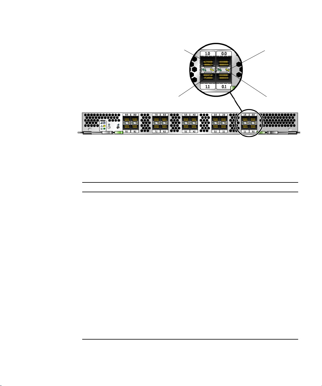
Port 0.0
Green LED
Port 0.0
Yellow LED
Port 0.1
Green LED
FIGURE 2-4 Port Level LEDs
TABLE 2-2 summarizes port LED indicator combinations.
TABLE 2-2 Port LED Indicator Status Definitions
Green LED Yellow LED State
Port 0.1
Yellow LED
On 1 Fast blink 1-Gb Link Rate - Normal operating state, link up
On 2 Fast blinks 2-Gb Link Rate - Normal operating state, link up
On 3 Fast blinks 4-Gb Link Rate - Normal operating state, link up
Off Off Wake-up failure (board failed)
Off On POST failure (board failed)
Off Slow blink Wake-up failure monitor
Off Fast blink Failure in POST
Off Flashing POST processing in progress
On Off Failure while functioning
On On Failure while functioning
Slow blink Off Normal, link down
Slow blink On Not defined
Slow blink Slow blink Off-line for download
Slow blink Fast blink Restricted off-line mode (waiting for restart)
Slow blink Flashing Restricted off-line mode, test active
Chapter 2 Hardware Installation and Removal 13
Page 26

Configuring the NEM For Hot-Plug Operation
To insert a NEM into the chassis while the system is running, you need to:
1. Physically install the module.
2. Prepare the NEM for hot-insertion by using the CMM integrated lights-out
management (ILOM) web interface or command-line-interface (CLI) and verify
the NEM has returned the expected feedback.
See “To Verify NEM Status” on page 16.
3. Verify in one of the ILOM interfaces that the module’s Ready to Remove status is
Not Ready.
Using the ILOM Web Interface
1. Log in to the ILOM web interface using the IP address of the active Chassis
Monitoring Module.
The first page of the ILOM web interface is displayed.
2. In the left navigation pane, select CMM.
The ILOM Version Information page is displayed.
3. Select the System Information tab, and then the Components tab.
The Component Management page is displayed. If you have installed a new NEM,
go to Step 4.
When you were preparing a NEM for a hot-remove, if you selected Prepare to
Remove from the Component Management page and corrected the problem without
removing the NEM or if you decided not to remove the NEM, complete Step 3a and
Step 3b.
a. Select the radio button next to the NEM that you want to hot-insert.
If you select the wrong NEM, click on the deselect icon at the top of the radio
button column.
b. From the Actions drop-down list, select Return to Service.
When you select the Return to Service option, the system recognizes the inserted
NEM, changes its Ready to Remove status to Not Ready, and lights the NEM’s
green OK indicator.
14 Sun StorageTek 4 Gb FC NEM 20-Port Host Bus Adapter User’s Guide • May 2007
Page 27

4. Verify that the selected NEM has returned the expected feedback.
See “To Verify NEM Status” on page 16.
Using the ILOM Command-Line Interface
1. Log in to the ILOM CLI of the active Chassis Monitoring Module.
2. For a list of components in your system, type:
show /CH
3. If you installed a new NEM, go to Step 4.
When you were preparing a NEM for a hot-remove, if you corrected the problem
without removing the NEM or you decided not to remove the NEM, complete the
following step:
Type this command to prepare a component for a hot-insert:
set /CH/component return_to_service_action=true
For example:
set /CH/NEM1 return_to_service_action=true
4. To verify that the NEM Ready to Remove status has changed to Not Ready, type:
show /CH/component prepare_to_remove_status
The system returns:
prepare_to_remove_status = Not Ready
5. Verify that the selected NEM has returned the expected feedback.
See the “To Verify NEM Status” on page 16.
Verifying a Hot-Insert Operation
You can replace many components in the chassis while the system is running by
using a hot-plug procedure.
To insert modules into the chassis while the system is running, you need to:
1. Physically install the module.
2. Verify in one of the ILOM interfaces that the module’s Ready to Remove status is
Not Ready and that the module has returned the expected feedback.
See “To Verify NEM Status” on page 16.
Chapter 2 Hardware Installation and Removal 15
Page 28

You can use the ILOM web interface or ILOM CLI to verify
Using the ILOM Web Interface
1. Log in to the ILOM web interface using the IP address of the active Chassis
Monitoring Module.
The first page of the ILOM web interface is displayed.
2. In the left navigation pane, select CMM (Chassis Monitoring Module).
The ILOM Version Information page is displayed.
3. Select the System Information tab, and then the Components tab.
The Component Management page is displayed.
4. Verify that the selected NEM has returned the expected feedback.
See “To Verify NEM Status” on page 16.
Using the ILOM CLI
1. Log in to the ILOM CLI of the active Chassis Monitoring Module.
2. For a list of components in your system, type:
show /CH
3. To verify that the NEM Ready to Remove status has changed to Not Ready, type:
show /CH/component prepare_to_remove_status
The system returns:
prepare_to_remove_status = Not Ready
4. Verify that the selected NEM has returned the expected feedback.
See “To Verify NEM Status” on page 16.
▼ To Verify NEM Status
See TABLE 2-3 for a description of the LED states for the NEM. See FIGURE 2-5 for the
location of the LEDs, Attention button, and Locator button.
1. Check the following LEDs to verify that the NEM is ready for a hot-plug
insertion.
16 Sun StorageTek 4 Gb FC NEM 20-Port Host Bus Adapter User’s Guide • May 2007
Page 29
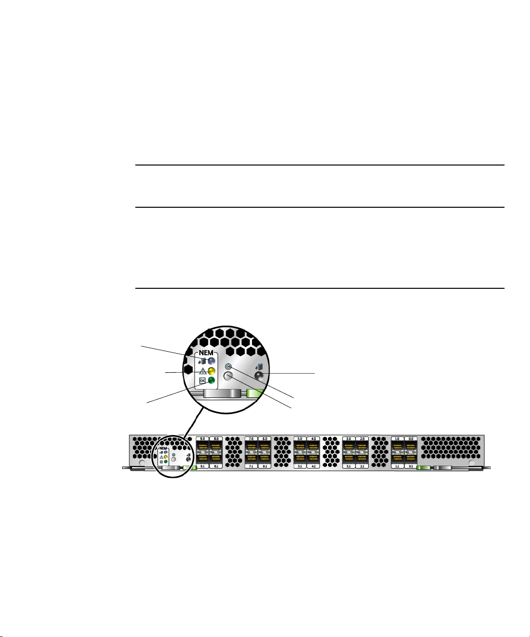
■ Green OK LED goes to Standby.
2. Activate the NEM by pressing the Attention button, and the green OK LED goes
to Slow blink.
■ When all links to active blades have been made, the green OK LED goes to Solid
On.
■ Ready to Remove status shows Not Ready in the ILOM interfaces.
TABLE 2-3 NEM LED Status
Ready-to-Remove
LED
Color: Blue
Location: Top
On Off Off Ready to remove
Off On Off Service attention required
Off Off Very slow blink Standby
Off Off Slow blink Connecting links to blades
Off Off On Links connected to blades
Ready-to-Remove
LED
Service Action Required
LED
OK LED (Power,
Attention, and Connected)
Service Action
Required LED
Color: Yellow
Location: Middle
OK LED (Power, Attention,
and Connected)
Color: Green
Location: Bottom
Attention button
Locator LED
Locator button
Status
FIGURE 2-5 LEDs, Attention and Locator Buttons
The Attention button enables you to activate (if inserting) or prepare to remove (if
removing) a NEM during a hot-plug operation.
Chapter 2 Hardware Installation and Removal 17
Page 30

The Locator button, when pressed momentarily, flashes a white light to assist in
locating the module. You can also activate the Locator LED remotely by executing a
command on the CMM.
Replacing a NEM
If a NEM fails or if you choose to change the I/O configuration, you will need to
replace it. You can remove and replace a NEM from a powered-on system using a
hot-plug operation, as well as from a powered-off system. When you remove a
NEM, you must replace the module within two minutes to prevent adjacent modules
from overheating.
If you are removing but not replacing the NEM, you also must install a NEM filler
panel to meet FCC limits for electromagnetic interference (EMI) and to ensure
proper airflow and cooling. If you encounter a problem with the NEM replacement,
see the Sun Blade 8000 Series Online Help System for troubleshooting steps.
▼ To Install the ID Chip Patch
1. Download patch 120223-18 from SunSolve:
http://sunsolve.sun.com
2. Install the patch onto each of the HBAs in the NEM.
Follow the installation instructions included in the patch Readme file.
▼ To Remove a NEM
1. Identify which NEM to replace.
If the yellow Service Action Required LED is lit, this indicates a problem with the
NEM and you might choose to replace it. Otherwise, if you want to change the I/O
configuration, you can choose any NEM to replace.
2. Prepare the NEM for a hot-plug procedure using either of these methods:
a. Press the Attention button on the NEM to initiate the hot-plug removal.
b. Use the ILOM web interface or the CLI to initiate the hot-plug removal.
If the NEM fails the hot-plug preparation and its Ready-to-Remove LED does not
light, see the Sun Blade 8000 Series Online Help System for troubleshooting steps.
18 Sun StorageTek 4 Gb FC NEM 20-Port Host Bus Adapter User’s Guide • May 2007
Page 31
3. When the blue Ready-to-Remove LED is lit on the NEM, physically remove the
NEM.
a. Remove all cables from the NEM.
b. Press the latch on both ejector levers inward at the same time.
c. Swing out the ejector levers to their fully open position.
d. Slide the NEM out of its slot.
Support the weight of the NEM with one hand at the bottom of the NEM.
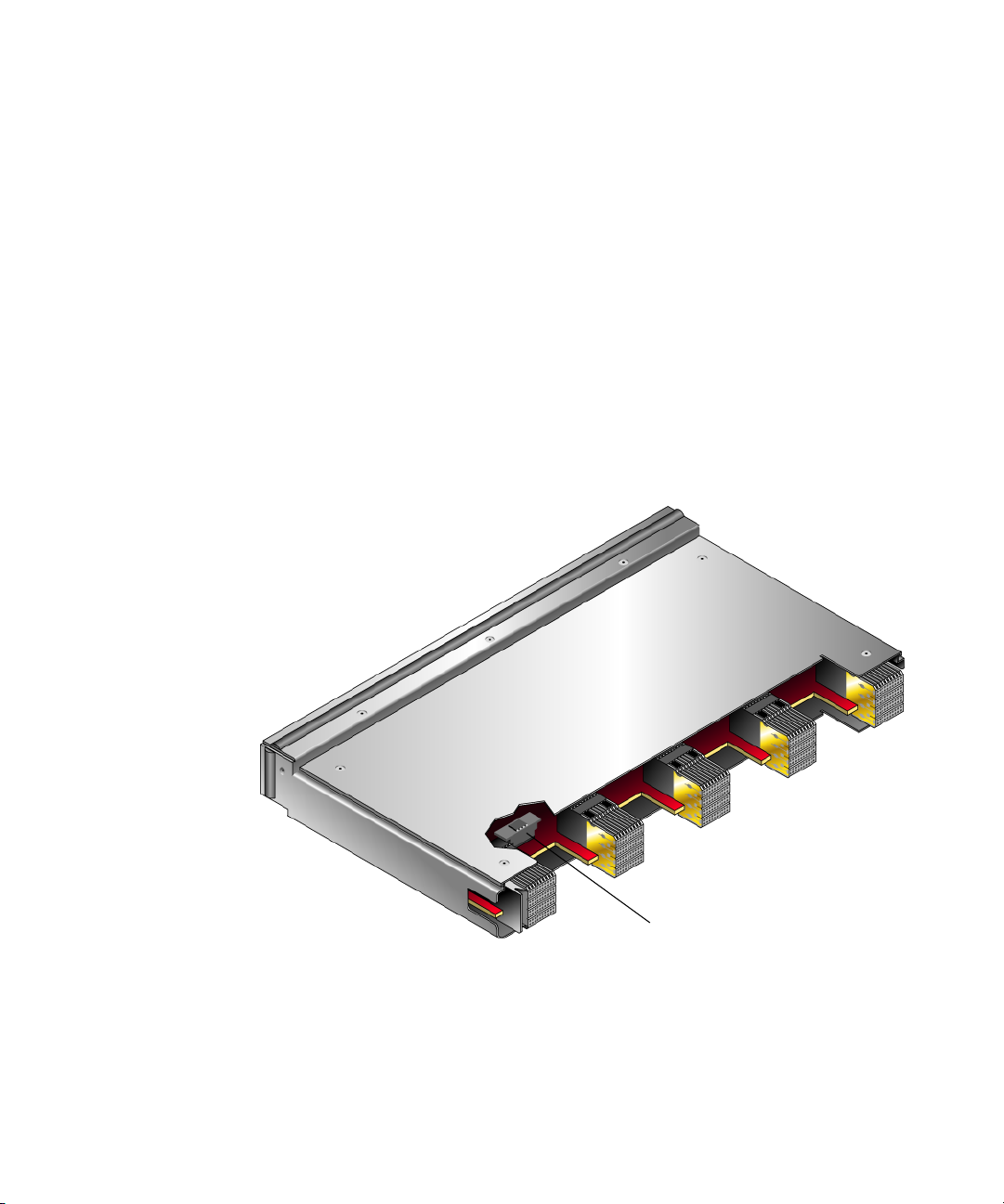
▼ To Replace the ID Chip
1. After you have removed the failed NEM from the chassis, locate the ID chip at the
back of the board (see
FIGURE 2-6).
ID chip
FIGURE 2-6 Location of ID Chip
2. Grasp the edges of the ID chip and pull straight up to remove it from the board.
3. Remove the ID chip from the new NEM, and install it onto the failed board that
you will be returning to Sun.
Chapter 2 Hardware Installation and Removal 19
Page 32

4. Install the ID chip onto the new board (see FIGURE 2-7).
a. Position the notched side of the ID chip to the left.
b. Place the ID chip directly over the connector.
c. Press down easily to seat the ID chip to the connector.
FIGURE 2-7 Installing the ID Chip
5. Install the replacement NEM into the chassis and reconnect the cables.
20 Sun StorageTek 4 Gb FC NEM 20-Port Host Bus Adapter User’s Guide • May 2007
Page 33

CHAPTER
3
HBA Software Installation
After you have completed the hardware installation, follow the instructions listed in
this chapter for your operating system to install the HBA driver and any other
utilities required for your installation.
This chapter contains the following topics:
■ “Driver Software for the Solaris OS” on page 21
■ “Driver Software for Linux OSs” on page 22
■ “Driver Software for Windows 2003 OS” on page 24
■ “Configuration and Diagnostic Utilities” on page 24
Driver Software for the Solaris OS
The latest HBA driver for the Solaris OS is included with Solaris 10 patch 120223-18.
See “Operating System Requirements” on page 4 for more information.
Solaris Diagnostic Support
Diagnostic support for the HBA is included in the SunVTS™ software beginning
with version 6.3. The SunVTS software is included with Solaris 10 11/06. It is also
available for download at:
http://www.sun.com/oem/products/vts
The emlxtest utility supports the following functions:
■ Connectivity verification
■ Firmware version and checksum test
21
Page 34

■ Self-test
■ Loopback tests
■ External
■ Internal, single-bit
■ Internal, 10-bit
■ Mailbox
Driver Software for Linux OSs
The Sun StorageTek 4 Gb FC NEM 20-Port Host Bus Adapter is supported by Red
Hat Enterprise Linux (RHEL) 4 U3 and U4 and Novell SUSE Linux Enterprise Server
9 Service Pack 3 (SLES9-SP3).
Red Hat Enterprise Linux
The HBA driver distributed with Red Hat Enterprise Linux (RHEL) 4 U3 and U4
supports the NEM. No additional driver updates are required.
Novell SUSE Linux Enterprise Server
The HBA driver distributed with SUSE Linux Enterprise Server 9 Service Pack 3
(SLES9-SP3) has the following known problems:
■ The HBA driver does not recognize the NEM device and will prevent it from
loading.
■ A system panic occurs when the HBA driver is unloaded.
To resolve these problems, update to the Emulex driver version 8.0.16.27 as
described in the next section.
▼ To Update the Driver
1. Run /sbin/update-pciids.
This command uploads the latest database which contains all supported PCI devices
by Linux, including the NEM.
2. Run YaST online.
You will be notified that the 8.0.16.27 is being installed.
22 Sun StorageTek 4 Gb FC NEM 20-Port Host Bus Adapter User’s Guide • May 2007
Page 35

Note – If you are running on a 2.6.5-7.244 kernel, you must install the Emulex
8.0.16.27 driver manually instead of updating using YaST. The driver RPM is
contained on the resource CD.
▼ To Install SLES9-SP3 to FC Disk
Before starting this procedure, you will need to create a driver update disk using the
ISO image for driver vesion 8.0.16.27 provided on the Sun Blade 8000 Series
Modular Systems resource CD. You can also download the Emulex driver update
disk from the Emulex or Novell support web site.
Emulex web site:
http://www.emulex.com/sun/support/nem-e11000.jsp
Novell web site:
http://forgeftp.novell.com/driverprocess/pub/update/SUN/sle9/DUD/emulex8.0.16.27/
To update the driver to version 8.0.16.27:
1. Install SLES9-SP3 using the normal install process.
2. When prompted for the update disk, load the driver update CD.
3. Continue the installation until all files are installed and the system reboots.
4. After the system reboots, follow the steps described in “To Update the Driver” on
page 22.
▼ To Build the Linux 2.6 Driver
You can build your own HBA driver by downloading the archived sources from the
Emulex support site.
1. To download the archived sources, go to:
http://www.emulex.com/sun/support/nem-e11000.jsp
2. Click the Linux 2.6 Kernel link.
3. Follow the instructions in the README file to build and install the 8.0.16.27
driver.
Chapter 3 HBA Software Installation 23
Page 36

Driver Software for Windows 2003 OS
The HBA driver for Windows 2003 OS is available for download at the Emulex
support site for Sun Microsystems.
http://www.emulex.com/sun/support/nem-e11000.jsp
▼ To Install Windows OS Driver and Application
Kits
Follow these steps to download the driver and AutoPilot installer:
1. Go to the Emulex support site for Sun Microsystems at:
http://www.emulex.com/sun/support/nem-e11000.jsp
2. Locate the driver section for Windows.
3. Download the Driver Kit by clicking the Download icon.
4. Click the PDF Manual icon to download installation, configuration, and
troubleshooting information for the Windows OS.
5. Install the driver and management utilities for the Windows OS as described in
the Emulex installation guide you downloaded in the previous step.
Configuration and Diagnostic Utilities
Use the HBAnywhere Remote Management Utility or the lputil command-line
interface (CLI) utility to configure the HBA. These utilities are available for Linux
and the Windows OS and provide support for the following functions:
■ Discover local and remote hosts, HBAs, targets, and LUNs
■ Reset HBAs
■ Set HBA driver parameters
■ Update firmware
■ Enable or disable the system BIOS
■ Run diagnostic tests on HBAs
24 Sun StorageTek 4 Gb FC NEM 20-Port Host Bus Adapter User’s Guide • May 2007
Page 37

■ Manage out-of-band HBAs
■ Manage local and in-band remote HBAs
See the Linux or Windows OS Emulex user manual for more information about
using the HBAnywhere and lputil utilities.
Chapter 3 HBA Software Installation 25
Page 38

26 Sun StorageTek 4 Gb FC NEM 20-Port Host Bus Adapter User’s Guide • May 2007
Page 39

CHAPTER
4
Release Notes
This chapter contains the latest supplementary information for the preceding
chapters in this guide. It contains the following topics:
■ Using the NEM With Sun StorEdge 3510 and 3511 Arrays
■ Solaris OS-Specific Issues
■ SUSE Linux Enterprise-Specific Issues
■ Windows Server 2003 OS-Specific Issues
For additional information related to the Sun StorageTek 4 Gb FC NEM 20-Port Host
Bus Adapter, see the Sun Blade 8000 Module System documentation set.
Using the NEM With Sun StorEdge 3510 and 3511 Arrays
You cannot connect the Sun StorEdge 3510 RAID array or Sun StorEdge 3511 FC
with SATA RAID array to the NEM on the same channel that use different speeds (1
Gb and 2 Gb). You can, however, mix 1-Gb and 2-Gb FC HBAs on different controller
channels. This limitation is due to the design of the Sun StorEdge 3510 RAID array's
port bypass circuitry and the inability of FC to support auto-negotiation in a multidrop loop configuration.
Host connectors channels 4 and 5 of the 3511 FC cannot auto-negotiate to 1 Gbit
which limits the number of hosts that can be direct-attached using 1 Gbit HBAs.
Channels 0 and 1 are able to auto-negotiate to 1 Gbit and allow up to four
connections in a dual-controller configuration or two connectors each in a singlecontroller configuration.
27
Page 40

Solaris OS-Specific Issues
The following known issues are related to installing, configuring, or operating the
NEM with the Solaris 10 OS.
Out of Option ROM Memory Error in System BIOS
Problem: A fully populated Sun Blade 8000 chassis with at least one NEM installed,
could cause the Out of Option ROM Memory Space error to occur during BIOS
POST.
Workaround: Disable some of the slots in the Basic Input/Output System (BIOS)
using the BIOS Setup utility. For information about disabling Option ROM, see BIOS
Option ROMs in the Sun Blade 8000 Series Online Information System.
For information about how to boot from a FC storage device connected to the NEM,
see Appendix A in the Sun Blade 8000 Series Installation Guide.
SUSE Linux Enterprise-Specific Issues
Problem: The HBA driver distributed with SUSE Linux Enterprise Server 9 Service
Pack 3 (SLES9-SP3) has the following known problems:
■ The HBA driver does not recognize the NEM device and will prevent it from
loading.
■ A system panic occurs when the HBA driver is unloaded.
Workaround: To resolve these problems, update to the Emulex driver version
8.0.16.27 as described in “To Update the Driver” on page 22.
Windows Server 2003 OS-Specific Issues
See the Emulex driver manuals for any known issues with the Windows OS drivers.
28 Sun StorageTek 4 Gb FC NEM 20-Port Host Bus Adapter User’s Guide • May 2007
Page 41

Chapter 4 Release Notes 29
Page 42

30 Sun StorageTek 4 Gb FC NEM 20-Port Host Bus Adapter User’s Guide • May 2007
Page 43

APPENDIX
A
Declaration of Conformity, Regulatory Compliance, and Safety Statements
This appendix contains the following information that applies to the Sun StorageTek
4 Gb FC NEM 20-Port Host Bus Adapter:
■ “Declaration of Conformity” on page 33
■ “Safety Agency Compliance Statement” on page 35
■ “Regulatory Compliance Statements” on page 47
31
Page 44

32 Sun StorageTek 4 Gb FC NEM Host Bus Adapter User’s Guide • May 2007
Page 45

<<
Declaration of Conformity
Compliance Model Number: 375-3385-XX
Product Family Name: Sun StorageTek 4 Gb FC NEM HBA
EMC
USA - FCC Class A
This equipment complies with Part 15 of the FCC Rules. Operation is subject to the following two conditions:
1) This equipment may not cause harmful interference.
2) This equipment must accept any interference that may cause undesired operation.
Manufactured by Emulex Corporation
European Union
This equipment complies with the following requirements of the EMC Directive 89/336/EEC:
As Information Technology Equipment (ITE) Class A per (as applicable):
EN 55022:1994 +A1:1995 +A2:1997 Class A
EN 61000-3-2:2000 +A2:2005 Pass
EN 61000-3-3:1995 +A1:2001 Pass
EN 55024:1998 +A1: 2001 +A2:2003 Required Limits:
IEC 61000-4-2 4 kV (Direct), 8 kV (Air)
IEC 61000-4-3 3 V/m
IEC 61000-4-4 1 kV AC Power Lines, 0.5 kV Signal and DC Power Lines
IEC 61000-4-5 1 kV AC Line-Line and Outdoor Signal Lines, 2 kV AC Line-Gnd, 0.5 kV DC Power Lines
IEC 61000-4-6 3V
IEC 61000-4-8 1 A/m
IEC 61000-4-11 Pass
Safety
This equipment complies with the following requirements of Low Voltage Directive 73/23/EEC:
EC Type Examination Certificates:
EN 60950-1:2001, 1st Edition
IEC 60950-1:2001, 1st Edition CB Scheme Certificate No. US-TUVR-3269
Evaluated to all CB Countries
UL and cUL/CSA 60950-1:2001, CSA C22.2 No. 60950-00 File: E157779 vol. x3
FDA DHHS Accession Number (Monitor Only)
Supplementary Information: This equipment was tested and complies with all the requirements for the CE Mark.
This equipment complies with the Restriction of Hazardous Substances (RoHS) directive 2002/95/EC.
______________________/S/____________________ _____________________/S/___________________
Dennis P. Symanski DATE Donald Cameron DATE
Worldwide Compliance Office
Sun Microsystems, Inc.
4150 Network Circle, MPK15-102
Santa Clara, CA 95054, USA
Tel: 650-786-3255
Fax: 650-786-3723
Program Manager/Quality Systems
Sun Microsystems Scotland, Limited
Blackness Road, Phase I, Main Bldg
Springfield, EH49 7LR
Scotland, United Kingdom
Tel: +44 1 506 672 539
Fax: +44 1 506 670 011
33
Page 46

34 Sun StorageTek 4 Gb FC NEM 20-Port Host Bus Adapter User’s Guide • May 2007
Page 47

Safety Agency Compliance Statement
Read this section before beginning any procedure. The
following text provides safety precautions to follow when
installing a Sun Microsystems product.
Safety Precautions
For your protection, observe the following safety
precautions when setting up your equipment:
■ Follow all cautions and instructions marked on the
equipment.
■ Ensure that the voltage and frequency of your power
source match the voltage and frequency inscribed on
the equipment’s electrical rating label.
■ Never push objects of any kind through openings in
the equipment. Dangerous voltages may be present.
Conductive foreign objects could produce a short
circuit that could cause fire, electric shock, or damage
to your equipment.
Symbols
The following symbols may appear in this book:
Caution – There is a risk of personal injury
and equipment damage. Follow the
instructions.
Depending on the type of power switch your device has,
one of the following symbols may be used:
On – Applies AC power to the system.
Off – Removes AC power from the system.
Standby – The On/Standby switch is in the
standby position.
Modifications to Equipment
Do not make mechanical or electrical modifications to the
equipment. Sun Microsystems is not responsible for
regulatory compliance of a modified Sun product.
Placement of a Sun Product
Caution – Do not block or cover the openings
of your Sun product. Never place a Sun
product near a radiator or heat register.
Failure to follow these guidelines can cause
overheating and affect the reliability of your
Sun product.
Caution – Hot surface. Avoid contact.
Surfaces are hot and may cause personal
injury if touched.
Caution – Hazardous voltages are present. To
reduce the risk of electric shock and danger to
personal health, follow the instructions.
Noise Level
Declared noise emissions in accordance with ISO 9296,
A-weighted, operating and idling:
Measure and Environment
L
(1B = 10 dB)
wAd
at or below 25ºC 8.0 B
at max ambient 8.4 B
bystander
L
pAm
at or below 25ºC 66 dB
at max ambient 69 dB
SELV Compliance
Safety status of I/O connections comply to SELV
requirements.
35
Page 48

Power Cord Connection
Caution – Sun products are designed to work
with power systems having a grounded
neutral (grounded return for DC-powered
products). To reduce the risk of electric shock,
do not plug Sun products into any other type
of power system. Contact your facilities
manager or a qualified electrician if you are
not sure what type of power is supplied to
your building.
Caution – Not all power cords have the same
current ratings. Do not use the power cord
provided with your equipment for any other
products or use. Household extension cords
do not have overload protection and are not
meant for use with computer systems. Do not
use household extension cords with your Sun
product.
The following caution applies only to devices with a
Standby power switch:
Caution – The power switch of this product
functions as a standby type device only. The
power cord serves as the primary disconnect
device for the system. Be sure to plug the
power cord into a grounded power outlet that
is nearby the system and is readily accessible.
Do not connect the power cord when the
power supply has been removed from the
system chassis.
Caution – For products with multiple power
cords, all power cords must be disconnected
to completely remove power from the system.
Battery Warning
Caution – There is danger of explosion if
batteries are mishandled or incorrectly
replaced. On systems with replaceable
batteries, replace only with the same
manufacturer and type or equivalent type
recommended by the manufacturer per the
instructions provided in the product service
manual. Do not disassemble batteries or
attempt to recharge them outside the system.
Do not dispose of batteries in fire. Dispose of
batteries properly in accordance with the
manufacturer’s instructions and local
regulations. Note that on Sun CPU boards,
there is a lithium battery molded into the realtime clock. These batteries are not customer
replaceable parts.
System Unit Cover
You must remove the cover of your Sun computer system
unit to add cards, memory, or internal storage devices. Be
sure toreplace the cover before powering on yourcomputer
system.
Caution – Do not operate Sun products
without the cover in place. Failure to take this
precaution may result in personal injury and
system damage.
The followingcaution applies only to deviceswith multiple
power cords:
36 Sun StorageTek 4 Gb FC NEM 20-Port Host Bus Adapter User’s Guide • May 2007
Page 49

Rack System Warning
The following warnings apply to Racks and Rack Mounted
systems.
CD and DVD Devices
The following caution applies to CD, DVD, and other
optical devices.
Caution – For safety, equipment should
always be loaded from the bottom up. That is,
install the equipment that will be mounted in
the lowest part of the rack first, then the next
higher systems, etc.
Caution – To prevent the rack from tipping
during equipment installation, the anti-tilt bar
on the rack must be deployed.
Caution – To prevent extreme operating
temperature within the rack insure that the
maximum temperature does not exceed the
product’s ambient rated temperatures.
Caution – To prevent extreme operating
temperatures due to reduced airflow
consideration should be made to the amount
of air flow that is required for a safe operation
of the equipment.
Laser Compliance Notice
Sun products that use laser technology comply withClass 1
laser requirements.
Caution – Use of controls, adjustments, or the
performance of procedures other than those
specified herein may result in hazardous
radiation exposure.
Conformité aux normes de sécurité
Veuillez lire attentivement cette section avant de
commencer. Ce texte traite des mesures de sécurité qu’il
convient de prendre pour l’installation d’un produit Sun
Microsystems.
Mesures de sécurité
Pour votre sécurité, nous vous recommandons de suivre
scrupuleusement lesmesures de sécuritéci-dessous lorsque
vous installez votre matériel:
■ Suivez tous les avertissements et toutes les
instructions inscrites sur le matériel.
■ Assurez-vous que la tension et la fréquence de votre
source d'alimentation correspondent à la tension et à
la fréquence indiquées sur l'étiquette de la tension
électrique nominale du matériel
■ N'introduisez jamais d'objets quels qu'ils soient dans
les ouvertures de l'équipement. Vous pourriez vous
trouver en présence de hautes tensions dangereuses.
Tout objet étranger conducteur risque de produire un
court-circuit pouvant présenter un risque d'incendie
ou de décharge électrique, ou susceptible
d'endommager le matériel.
Class 1 Laser Product
Luokan 1 Laserlaite
Klasse 1 Laser Apparat
Laser Klasse 1
Safety Agency Compliance Statement 37
Page 50

Symboles
Vous trouverez ci-dessous la signification des différents
symboles utilisés:
Attention – Vous risquez d'endommager le
matériel ou de vous blesser. Veuillez suivre les
instructions.
Attention – Surfaces brûlantes. Evitez tout
contact. Les surfaces sont brûlantes. Vous
risquez de vous blesser si vous les touchez.
Attention – Tensions dangereuses. Pour
réduire les risques de décharge électrique et
de danger physique, observez les consignes
indiquées.
Selon le type d'interrupteur marche/arrêt dont votre
appareil est équipé, l'un des symboles suivants sera utilisé:
Marche – Met le système sous tension
alternative.
Positionnement d’un produit Sun
Attention – Evitez d'obstruer ou de recouvrir
les orifices de votre produit Sun. N'installez
jamais un produit Sun près d'un radiateur ou
d'une source de chaleur. Si vous ne respectez
pas ces consignes, votre produit Sun risque de
surchauffer et son fonctionnement en sera
altéré.
Niveau de pression acoustique
Valeurs déclaréesd'émission acoustique enconformité avec
la normeISO 9296, PondéréA, enfonctionnement et inactif:
Mesure et environnement
L
(1B = 10 dB)
wAd
à ou en dessous de 25ºC 8.0 B
à temp. ambiante maxi. 8.4 B
assistant
L
pAm
à ou en dessous de 25ºC 66 dB
à temp. ambiante maxi. 69 dB
Arret – Met le système hors tension
alternative.
Veilleuse – L'interrupteur Marche/Veille est
sur la position de veille.
Modification du matériel
N'apportez aucune modification mécanique ou électrique
au matériel. Sun Microsystems décline toute responsabilité
quant à la non-conformité éventuelle d'un produit Sun
modifié.
38 Sun StorageTek 4 Gb FC NEM 20-Port Host Bus Adapter User’s Guide • May 2007
Conformité SELV
Le niveau de sécurité des connexions E/S est conforme aux
normes SELV.
Connexion du cordon d’alimentation
Attention – Les produits Sun sont conçus
pour fonctionner avec des systèmes
d'alimentation équipés d'un conducteur
neutre relié à la terre (conducteur neutre pour
produits alimentés en CC). Pour réduire les
risques de décharge électrique, ne branchez
jamais les produits Sun sur une source
d'alimentation d'un autre type. Contactez le
gérant de votre bâtiment ou un électricien
agréé si vous avez le moindre doute quant au
type d'alimentation fourni dans votre
bâtiment.
Page 51
Attention – Tous les cordons d'alimentation
ne présentent pas les mêmes caractéristiques
électriques. Les cordons d'alimentation à
usage domestique ne sont pas protégés contre
les surtensions et ne sont pas conçus pour être
utilisés avec des ordinateurs. N'utilisez jamais
de cordon d'alimentation à usage domestique
avec les produits Sun.
L'avertissement suivant s'applique uniquement aux
systèmes équipés d'un interrupteur Veille:
Attention – L'interrupteur d'alimentation de
ce produit fonctionne uniquement comme un
dispositif de mise en veille. Le cordon
d'alimentation constitue le moyen principal de
déconnexion de l'alimentation pour le
système. Assurez-vous de le brancher dans
une prise d'alimentation mise à la terre près
du système et facile d'accès. Ne le branchez
pas lorsque l'alimentation électrique ne se
trouve pas dans le châssis du système.
L'avertissement suivant s'applique uniquement aux
systèmes équipés de plusieurs cordons d'alimentation:
Mise en garde relative aux batteries
Attention – Les batteries risquent d’exploser
en cas de manipulation maladroite ou de
remplacement incorrect. Pour les systèmes
dont les batteries sont remplaçables, effectuez
les remplacements uniquement selon le
modèle du fabricant ou un modèle équivalent
recommandé par le fabricant, conformément
aux instructions fournies dans le manuel de
service du système. N’essayez en aucun cas de
démonter les batteries, ni de les recharger hors
du système. Ne les jetez pas au feu. Mettez-les
au rebut selon les instructions du fabricant et
conformément à la législation locale en
vigueur. Notez que sur les cartes processeur
de Sun, une batterie au lithium a été moulée
dans l'horloge temps réel. Les batteries ne sont
pas des pièces remplaçables par le client.
Couvercle de l'unité
Pour ajouterdes cartes,de la mémoire ou des périphériques
de stockage internes, vous devez retirer le couvercle de
votre système Sun. Remettez le couvercle supérieur en
place avant de mettre votre système sous tension.
Attention – Pour mettre un système équipé de
plusieurs cordons d'alimentation hors tension,
il est nécessaire de débrancher tous les
cordons d'alimentation.
Attention – Ne mettez jamais des produits
Sun sous tension si leur couvercle supérieur
n'est pas mis en place. Si vous ne prenez pas
ces précautions, vous risquez de vous blesser
ou d'endommager le système.
Mise en garde relative au système en rack
La mise en garde suivante s'applique aux racks et aux
systèmes montés en rack.
Attention – Pour des raisons de sécurité, le
matériel doit toujours être chargé du bas vers
le haut. En d'autres termes, vous devez
installer, en premier, le matériel qui doit se
trouver dans la partie la plus inférieure du
rack, puis installer le matériel sur le niveau
suivant, etc.
Safety Agency Compliance Statement 39
Page 52

Attention – Afin d'éviter que le rack ne
penche pendant l'installation du matériel, tirez
la barre anti-basculement du rack.
Attention – Pour éviter des températures de
fonctionnement extrêmes dans le rack,
assurez-vous que la température maximale ne
dépasse pas la fourchette de températures
ambiantes du produit déterminée par le
fabricant.
Attention – Afin d'empêcher des
températures de fonctionnement extrêmes
provoquées par une aération insuffisante,
assurez-vous de fournir une aération
appropriée pour un fonctionnement du
matériel en toute sécurité
Einhaltung sicherheitsbehördlicher Vorschriften
Lesen Sie vor dem Ausführen von Arbeiten diesen
Abschnitt. Im folgenden Text werden Sicherheitsvorkehrungen beschrieben, die Sie bei der Installation eines
Sun Microsystems-Produkts beachten müssen.
Sicherheitsvorkehrungen
Treffen Sie zu Ihrem eigenen Schutzbei der Installation des
Geräts die folgenden Sicherheitsvorkehrungen:
■ Beachten Sie alle auf den Geräten angebrachten
Warnhinweise und Anweisungen.
■ Stellen Sie sicher, dass Spannung und Frequenz der
Stromversorgung den Nennleistungen auf dem am
Gerät angebrachten Etikett entsprechen.
■ Führen Sie niemals Fremdobjekte in die Öffnungen
am Gerät ein. Es können gefährliche Spannungen
anliegen. Leitfähige Fremdobjekte können einen
Kurzschluss verursachen, der einen Brand, Stromschlag oder Geräteschaden herbeiführen kann.
Avis de conformité des appareils laser
Les produitsSun quifont appelaux technologieslasers sont
conformes aux normes de la classe 1 en la matière.
Class 1 Laser Product
Luokan 1 Laserlaite
Klasse 1 Laser Apparat
Laser Klasse 1
Périphériques CD et DVD
L'avertissement suivant s'applique aux périphériques CD,
DVD et autres périphériques optiques:
Attention – L'utilisation de contrôles et de
réglages ou l'application de procédures autres
que ceux spécifiés dans le présent document
peuvent entraîner une exposition à des
radiations dangereuses.
Symbole
Die Symbole in diesem Handbuch haben folgende
Bedeutung:
Achtung – Gefahr von Verletzung und
Geräteschaden. Befolgen Sie die Anweisungen.
Achtung – Heiße Oberfläche. Nicht berühren,
da Verletzungsgefahr durch heiße Oberfläche
besteht.
Achtung – Gefährliche Spannungen. Befolgen
Sie die Anweisungen, um Stromschläge und
Verletzungen zu vermeiden.
40 Sun StorageTek 4 Gb FC NEM 20-Port Host Bus Adapter User’s Guide • May 2007
Page 53

Je nach Netzschaltertyp an Ihrem Gerät kann eines der
folgenden Symbole verwendet werden:
Ein – Versorgt das System mit Wechselstrom.
Aus– Unterbricht die Wechselstromzufuhr
zum Gerät.
Wartezustand – Der Ein-/Standby-Netzschalter befindet sich in der Standby-Position.
Modifikationen des Geräts
Nehmen Sie keine elektrischen oder mechanischen
Gerätemodifikationen vor. Sun Microsystems ist für die
Einhaltung der Sicherheitsvorschriften von modifizierten
Sun-Produkten nicht haftbar.
Lautstärke
Angegebene Geräuschentwicklung im Einklang mit ISO
9296, A-bewertet, in Betrieb und im Ruhezustand:
Messwert und Umgebung
L
(1B = 10 dB)
wAd
bei oder unter 25ºC 8.0 B
bei max. Umgebung 8.4 B
Umstehende
L
pAm
bei oder unter 25ºC 66 dB
bei max. Umgebung 69 dB
SELV-Konformität
Der Sicherheitsstatus der E/A-Verbindungen entspricht
den SELV-Anforderungen.
Aufstellung von Sun-Geräten
Achtung – Geräteöffnungen Ihres SunProdukts dürfen nicht blockiert oder
abgedeckt werden. Sun-Geräte sollten niemals
in der Nähe von Heizkörpern oder Heißluftklappen aufgestellt werden. Die Nichtbeachtung dieser Richtlinien kann Überhitzung
verursachen und die Zuverlässigkeit Ihres
Sun-Geräts beeinträchtigen.
Anschluss des Netzkabels
Achtung – Sun-Geräte sind für
Stromversorgungssysteme mit einem
geerdeten neutralen Leiter (geerdeter
Rückleiter bei gleichstrombetriebenen
Geräten) ausgelegt. Um die Gefahr von
Stromschlägen zu vermeiden, schließen Sie
das Gerät niemals an andere Stromversorgungssysteme an. Wenden Sie sich an den
zuständigen Gebäudeverwalter oder an einen
qualifizierten Elektriker, wenn Sie nicht sicher
wissen, an welche Art von Stromversorgungssystem Ihr Gebäude angeschlossen ist.
Achtung – Nicht alle Netzkabel verfügen
über die gleichen Nennwerte. Herkömmliche,
im Haushalt verwendete Verlängerungskabel
besitzen keinen Überlastschutz und sind
daher für Computersysteme nicht geeignet.
Verwenden Sie bei Ihrem Sun-Produkt keine
Haushalts-Verlängerungskabel.
Safety Agency Compliance Statement 41
Page 54

Die folgende Warnung gilt nur für Geräte mit StandbyNetzschalter:
Achtung – Beim Netzschalter dieses Geräts
handelt es sich nur um einen Ein/StandbySchalter. Zum völligen Abtrennen des Systems
von der Stromversorgung dient hauptsächlich
das Netzkabel. Stellen Sie sicher, dass das
Netzkabel an eine frei zugängliche geerdete
Steckdose in der Nähe des Systems angeschlossen ist. Schließen Sie das Stromkabel
nicht an, wenn die Stromversorgung vom
Systemchassis entfernt wurde.
Die folgende Warnung gilt nur für Geräte mit mehreren
Netzkabeln:
Achtung – Bei Produkten mit mehreren Netzkabeln müssen alle Netzkabel abgetrennt werden, um das System völlig von der Stromversorgung zu trennen.
Warnung bezüglich Batterien
Achtung – Bei unsachgemäßer Handhabung
oder nicht fachgerechtem Austausch der
Batterien besteht Explosionsgefahr. Verwenden Sie bei Systemen mit austauschbaren
Batterien ausschließlich Ersatzbatterien
desselben Typs und Herstellers bzw. einen
entsprechenden, vom Hersteller gemäß den
Anweisungen im Service-Handbuch des
Produkts empfohlenen Batterietyp. Versuchen
Sie nicht, die Batterien auszubauen oder
außerhalb des Systems wiederaufzuladen.
Werfen Sie die Batterien nicht ins Feuer.
Entsorgen Sie die Batterien entsprechend den
Anweisungen des Herstellers und den vor Ort
geltenden Vorschriften. CPU-Karten von Sun
verfügen über eine Echtzeituhr mit integrierter Lithiumbatterie. Diese Batterie darf nur
von einem qualifizierten Servicetechniker ausgewechselt werden.
Gehäuseabdeckung
Sie müssen die Abdeckung Ihres Sun-Computersystems
entfernen, um Karten, Speicher oderinterne Speichergeräte
hinzuzufügen. Bringen Sie vor dem Einschalten des
Systems die Gehäuseabdeckung wieder an.
Achtung – Nehmen Sie Sun-Geräte nicht ohne
Abdeckung in Betrieb. Die Nichtbeachtung
dieses Warnhinweises kann Verletzungen oder
Geräteschaden zur Folge haben.
Warnungen bezüglich in Racks eingebauter Systeme
Die folgenden Warnungen gelten für Racks und in Racks
eingebaute Systeme:
Achtung – Aus Sicherheitsgründen sollten
sämtliche Geräte von unten nach oben in
Racks eingebaut werden. Installieren Sie also
zuerst die Geräte, die an der untersten
Position im Rack eingebaut werden, gefolgt
von den Systemen, die an nächsthöherer Stelle
eingebaut werden, usw.
Achtung – Verwenden Sie beim Einbau den
Kippschutz am Rack, um ein Umkippen zu
vermeiden.
Achtung – Um extreme Betriebstemperaturen
im Rack zu vermeiden, stellen Sie sicher, dass
die Maximaltemperatur die Nennleistung der
Umgebungstemperatur für das Produkt nicht
überschreitet
Achtung – Um extreme Betriebstemperaturen
durch verringerte Luftzirkulation zu vermeiden, sollte die für den sicheren Betrieb des
Geräts erforderliche Luftzirkulation eingesetzt
werden.
42 Sun StorageTek 4 Gb FC NEM 20-Port Host Bus Adapter User’s Guide • May 2007
Page 55

Hinweis zur Laser-Konformität
Sun-Produkte, die die Laser-Technologie verwenden,
entsprechen den Laser-Anforderungen der Klasse 1.
Precaución – Existe el riesgo de que se
produzcan lesiones personales y daños en el
equipo. Siga las instrucciones.
Class 1 Laser Product
Luokan 1 Laserlaite
Klasse 1 Laser Apparat
Laser Klasse 1
CD- und DVD-Geräte
Die folgende Warnung gilt für CD-, DVD- und andere
optische Geräte:
Achtung – Die hier nicht aufgeführte
Verwendung von Steuerelementen,
Anpassungen oder Ausführung von
Vorgängen kann eine gefährliche
Strahlenbelastung verursachen.
Normativas de seguridad
Lea esta sección antes de realizar cualquier operación. En
ella seexplican las medidasde seguridad que debe tomaral
instalar un producto de Sun Microsystems.
Medidas de seguridad
Para su protección, tome las medidas de seguridad
siguientes durante la instalación del equipo:
■ Siga todos los avisos e instrucciones indicados en el
equipo.
■ Asegúrese de que el voltaje y frecuencia de la fuente
de alimentación coincidan con el voltaje y frecuencia
indicados en la etiqueta de clasificación eléctrica del
equipo.
■ No introduzca objetos de ningún tipo por las rejillas
del equipo, ya que puede quedar expuesto a voltajes
peligrosos. Los objetos conductores extraños pueden
producir cortocircuitos y, en consecuencia, incendios,
descargas eléctricas o daños en el equipo.
Símbolos
En este documento aparecen los siguientes símbolos:
Precaución – Superficie caliente. Evite todo
contacto. Las superficies están calientes y
pueden causar lesiones personales si se tocan.
Precaución – Voltaje peligroso. Para reducir
el riesgo de descargas eléctricas y lesiones
personales, siga las instrucciones.
En función del tipo de interruptor de alimentación del que
disponga el dispositivo, se utilizará uno de los símbolos
siguientes:
Encendido – Suministra alimentación de CA
al sistema.
Apagado – Corta la alimentación de CA del
sistema.
Espera – El interruptor de encendido/espera
está en la posición de espera.
Modificaciones en el equipo
No realicemodificaciones de tipo mecánico ni eléctrico en el
equipo. Sun Microsystems no se hace responsable del
cumplimiento de normativas en caso de que un producto
Sun se haya modificado.
Colocación de un producto Sun
Precaución – No obstruya ni tape las rejillas
del producto Sun. Nunca coloque un producto
Sun cerca de radiadores ni fuentes de calor. Si
no sigue estas indicaciones, el producto Sun
podría sobrecalentarse y la fiabilidad de su
funcionamiento se vería afectada.
Safety Agency Compliance Statement 43
Page 56

Nivel de ruido
Emisiones acústicas declaradas de acuerdo con la norma
ISO 9296 (decibelios A), en funcionamiento y reposo:
La siguiente medida solamente se aplica a aquellos
dispositivos que dispongan de un interruptor de
alimentación de espera:
Medición y condiciones ambientales
L
(1B = 10 dB)
wAd
a 25ºC o menos: 8.0 B
máxima temp. ambiente: 8.4 B
(posición de observación)
L
pAm
a 25ºC o menos: 66 dB
máxima temp. ambiente: 69 dB
Cumplimiento de la normativa para instalaciones SELV
Las condiciones de seguridad de las conexiones de entrada
y salidacumplen losrequisitos para instalaciones SELV (del
inglés Safe Extra Low Voltage, voltaje bajo y seguro).
Conexión del cable de alimentación
Precaución – Los productos Sun se han
diseñado para funcionar con sistemas de
alimentación que cuenten con un conductor
neutro a tierra (con conexión a tierra de
regreso para los productos con alimentación
de CC). Para reducir el riesgo de descargas
eléctricas, no conecte ningún producto Sun a
otro tipo de sistema de alimentación. Póngase
en contacto con el encargado de las
instalaciones de su empresa o con un
electricista cualificado en caso de que no esté
seguro del tipo de alimentación del que se
dispone en el edificio.
Precaución – No todos los cables de
alimentación tienen la misma clasificación
eléctrica. Los alargadores de uso doméstico no
cuentan con protección frente a sobrecargas y
no están diseñados para su utilización con
sistemas informáticos. No utilice alargadores
de uso doméstico con el producto Sun.
Precaución – El interruptor de alimentación
de este producto funciona solamente como un
dispositivo de espera. El cable de alimentación
hace las veces de dispositivo de desconexión
principal del sistema. Asegúrese de que
conecta el cable de alimentación a una toma
de tierra situada cerca del sistema y de fácil
acceso. No conecte el cable de alimentación si
la unidad de alimentación no se encuentra en
el bastidor del sistema.
La siguiente medida solamente se aplica a aquellos
dispositivos que dispongan de varios cables de
alimentación:
Precaución – En los productos que cuentan
con varios cables de alimentación, debe
desconectar todos los cables de alimentación
para cortar por completo la alimentación
eléctrica del sistema.
Advertencia sobre las baterías
Precaución – Si las baterías no se manipulan
o reemplazan correctamente, se corre el riesgo
de que estallen. En los sistemas que cuentan
con baterías reemplazables, reemplácelas sólo
con baterías del mismo fabricante y el mismo
tipo, o un tipo equivalente recomendado por
el fabricante, de acuerdo con las instrucciones
descritas en el manual de servicio del
producto. No desmonte las baterías ni intente
recargarlas fuera del sistema. No intente
deshacerse de las baterías echándolas al fuego.
Deshágase de las baterías correctamente de
acuerdo con las instrucciones del fabricante y
las normas locales. Tenga en cuenta que en las
placas CPU de Sun, hay una batería de litio
incorporada en el reloj en tiempo real. Los
usuarios no deben reemplazar este tipo de
baterías.
44 Sun StorageTek 4 Gb FC NEM 20-Port Host Bus Adapter User’s Guide • May 2007
Page 57
Cubierta de la unidad del sistema
Debe extraer la cubierta de la unidad del sistema
informático Sun para instalar tarjetas, memoria o
dispositivos de almacenamiento internos. Vuelva a colocar
la cubierta antes de encender el sistema informático.
Precaución – No ponga en funcionamiento
los productos Sun que no tengan colocada la
cubierta. De lo contrario, puede sufrir lesiones
personales y ocasionar daños en el sistema.
Advertencia sobre el sistema en bastidor
Las advertencias siguientes se aplican a los sistemas
montados en bastidor y a los propios bastidores.
Precaución – Por seguridad, siempre deben
montarse los equipos de abajo arriba. A saber,
primero debe instalarse el equipo que se
situará en el bastidor inferior; a continuación,
el que se situará en el siguiente nivel, etc.
Precaución – Para evitar que el bastidor se
vuelque durante la instalación del equipo,
debe extenderse la barra antivolcado del
bastidor.
Aviso de cumplimiento de la normativa para la utilización de láser
Los productos Sunque utilizantecnología lásercumplen los
requisitos establecidos para los productos láser de clase 1.
Class 1 Laser Product
Luokan 1 Laserlaite
Klasse 1 Laser Apparat
Laser Klasse 1
Dispositivos de CD y DVD
La siguiente medida se aplica a los dispositivos de CD y
DVD, así como a otros dispositivos ópticos:
Precaución – La utilización de controles,
ajustes o procedimientos distintos a los aquí
especificados puede dar lugar a niveles de
radiación peligrosos.
Nordic Lithium Battery Cautions
Norge
Precaución – Para evitar que se alcance una
temperatura de funcionamiento extrema en el
bastidor, asegúrese de que la temperatura
máxima no sea superior a la temperatura
ambiente establecida como adecuada para el
producto.
Precaución – Para evitar que se alcance una
temperatura de funcionamiento extrema
debido a una circulación de aire reducida,
debe considerarse la magnitud de la
circulación de aire requerida para que el
equipo funcione de forma segura.
Advarsel – Litiumbatteri — Eksplosjonsfare.
Ved utskifting benyttes kun batteri som
anbefalt av apparatfabrikanten. Brukt batteri
returneres apparatleverandøren.
Sverige
Varning – Explosionsfara vid felaktigt
batteribyte. Använd samma batterityp eller en
ekvivalent typ som rekommenderas av
apparattillverkaren. Kassera använt batteri
enligt fabrikantens instruktion.
Safety Agency Compliance Statement 45
Page 58
Danmark
Suomi
Advarsel! – Litiumbatteri — Eksplosionsfare
ved fejlagtig håndtering. Udskiftning må kun
ske med batteri af samme fabrikat og type.
Levér det brugte batteri tilbage til
leverandøren.
Varoitus – Paristo voi räjähtää, jos se on
virheellisesti asennettu. Vaihda paristo
ainoastaan laitevalmistajan suosittelemaan
tyyppiin. Hävitä käytetty paristo valmistajan
ohjeiden mukaisesti.
46 Sun StorageTek 4 Gb FC NEM 20-Port Host Bus Adapter User’s Guide • May 2007
Page 59
Regulatory Compliance Statements
Your Sun product is marked to indicate its compliance class:
• Federal Communications Commission (FCC) — USA
• Industry Canada Equipment Standard for Digital Equipment (ICES-003) — Canada
• Bureau of Standards Metrology and Inspection (BSMI) — Taiwan
Please read the appropriate section that corresponds to the marking on your Sun product before attempting to install the
product.
FCC Class A Notice
This device complies with Part 15 of the FCC Rules. Operation is subject to the following two conditions:
1. This device may not cause harmful interference.
2. This device must accept any interference received, including interference that may cause undesired operation. Note: This equipment has been tested and found to comply with the limits for a Class A digital device, pursuant to Part 15 of
the FCC Rules. These limits are designed to provide reasonable protection against harmful interference when the equipment
is operated in a commercial environment. This equipment generates, uses, and can radiate radio frequency energy, and if it is
not installed and used in accordance with theinstruction manual, itmay cause harmfulinterference to radiocommunications.
Operation of this equipment in a residential areais likely tocause harmful interference,in which casethe user willbe required
to correct the interference at his own expense.
Modifications: Any modifications made to thisdevice thatare not approvedby SunMicrosystems, Inc.may voidthe authority
granted to the user by the FCC to operate this equipment.
ICES-003 Class A Notice - Avis NMB-003, Classe A
This Class A digital apparatus complies with Canadian ICES-003.
Cet appareil numérique de la classe A est conforme à la norme NMB-003 du Canada.
47
Page 60

BSMI Class A Notice
The following statement is applicable to products shipped to Taiwan and marked as Class A on the product compliance
label.
D33728
48 Sun StorageTek 4 Gb FC NEM 20-Port Host Bus Adapter User’s Guide • May 2007
Page 61

CCC Class A Notice
The following statement is applicable to products shipped to China and marked with “Class A” on the product’s compliance
label.
Korean MIC Class A Statement
Regulatory Compliance Statements 49
Page 62

50 Sun StorageTek 4 Gb FC NEM 20-Port Host Bus Adapter User’s Guide • May 2007
Page 63

Index
A
Attention button, 17
B
BIOS POST, 28
C
cable length, maximum, 2
channel LEDs, 13
chassis monitoring module (CMM)
firmware, 5
using ILOM, 14
compliance statements
regulatory, 47
safety agency, 35
connecting links to blades status
status
NEM LED, 17
connectors
external FC, 2
NEM port, 9
D
Declaration of Conformity, 33
diagnostics, 24
F
FC switches, 6
Fibre Channel topology, 2
firmware
CMM, 5
service processor, 5
update, 24
H
HBA drivers
known issues, 28
HBAnywhere Remote Management Utility, 24
hot-plug operation
configuring, 14
verifying, 15
I
ID Chip
feature, 3
patch, 18
replace, 19
ILOM
command-line interface (CLI), 15
web interface, 14
in-band remote HBAs, 25
E
electrostatic discharge (ESD) handling
precautions, 8
ESD wrist strap, 8
L
LEDs
NEM, 17
port, 13
lights-out management (ILOM) interface, 14
link rate, 13
51
Page 64

links connected to blades status, 17
Linux
driver, known issues, 28
supported versions, 4
Locator LED and button, 17
LUNs, discover, 24
M
memory, 2
N
NEM
activating, 17
configuring for hot-plug, 14
installing, 9
interface, 2
LED status, 17
part number, 2
restrictions, 27
status, verifying, 16
NEM port numbering, 11
O
operating systems
supported, 5
operating systems, supported versions, 4
optical cable specifications, 11
Out of Option ROM Memory Space error, 28
out-of-band HBAs, 25
S
safety precautions, 35
service attention required status, 17
service processor (SP) firmware, 5
SFP fiber-optic transceivers, 2
Small Form-Factor Pluggable (SFP), 2
Solaris OS
known issues, 28
patches, 4
supported versions, 4
standby status, 17
status
NEM LED, 17
port LED definitions, 13
storage systems, 5
Sun Blade 8000 Modular Systems, 5
Sun StorEdge 3510/3511 RAID arrays, 27
sunsolve.sun.com, 18
switches, supported, 6
system BIOS
enable and disable, 24
system panic, 28
W
Windows 2003 OS
driver, 24
supported versions, 4
P
patches
required Solaris, 4
PCI transfer rate, 2
port LEDs, 13
port numbering, 11
POST failure, 13
power-on self tests
BIOS, 28
NEM, 12
R
ready to remove status, 17
regulatory compliance statements, 47
Restriction of Hazardous Substances (RoHS)
directive, 33
52 Sun StorageTek 4 Gb FC NEM 20-Port Host Bus Adapter User’s Guide • May 2007
 Loading...