

Page 1

SPARCstation 5 Service Manual
Sun Microsystems Computer Company
A Sun Microsystems, Inc. Business
901 San Antonio Road Palo Alto, CA 94303-4900 USA
650 960-1300
fax 650 969-9131
Part No.: 801-6396-11
Revision A, August 1994
Page 2

1994 Sun Microsystems,Inc.,901SanAntonioRoad,PaloAlto,California94303-4900U.S.A.
All rights reserved.
This productordocumentisprotectedbycopyrightanddistributedunderlicensesrestrictingitsuse,copying,distribution,anddecompilation.
No part of this productordocumentmaybereproducedinanyformbyanymeanswithoutpriorwrittenauthorizationofSunanditslicensors,
if any.
Portions of this productmaybederivedfromtheUNIX®system,licensedfromNovell,Inc.,andfromtheBerkeley4.3BSDsystem,licensed
fromtheUniversityofCalifornia.UNIXisaregisteredtrademarkintheUnitedStatesandinothercountriesandisexclusivelylicensedby
X/Open Company Ltd. Third-partysoftware,includingfonttechnologyinthisproduct,isprotectedbycopyrightandlicensedfrom Sun’s
suppliers. RESTRICTED RIGHTS: Use, duplication, or disclosurebytheU.S.GovernmentissubjecttorestrictionsofFAR 52.227-14(g)(2)(6/87)
and FAR52.227-19(6/87),orDFAR252.227-7015(b)(6/95)andDFAR 227.7202-3(a).
Sun, Sun Microsystems,theSunlogo,andSolarisaretrademarksorregisteredtrademarksofSunMicrosystems, Inc. in the United States and in
other countries. All SPARC trademarks are used under licenseandaretrademarksorregisteredtrademarksofSPARCInternational,Inc.inthe
United States and in other countries. ProductsbearingSPARC trademarks arebaseduponanarchitecturedevelopedbySunMicrosystems,Inc.
The OPEN LOOK® and Sun™ Graphical User Interfaces weredevelopedbySunMicrosystems,Inc.foritsusersandlicensees.Sun
acknowledges the pioneering effortsofXeroxCorporationinresearchinganddevelopingtheconceptofvisualorgraphicaluserinterfacesfor
the computer industry. Sun holds a nonexclusive licensefromXeroxtotheXeroxGraphicalUserInterface,whichlicensealsocoversSun’s
licensees who implement OPEN LOOK GUIs and otherwise comply with Sun’s writtenlicenseagreements.
THIS PUBLICATIONISPROVIDED“ASIS”WITHOUTWARRANTYOFANYKIND,EITHEREXPRESSORIMPLIED,INCLUDING,BUT
NOT LIMITED TO,THEIMPLIEDWARRANTIES OF MERCHANTABILITY,FITNESSFORAPARTICULAR PURPOSE, OR NONINFRINGEMENT.
Copyright 1994 Sun Microsystems,Inc.,901SanAntonioRoad,PaloAlto,Californie94303-4900U.S.A.Tousdroitsréservés.
Ce produitoudocumentestprotégéparuncopyrightetdistribuéavecdeslicencesquienrestreignentl’utilisation,lacopieetladécompilation.
Aucune partie de ce produitoudesadocumentationassociéenepeutêtrereproduitesousaucuneforme,parquelquemoyenquecesoit,sans
l’autorisation préalable et écrite de Sun et desesbailleursdelicence,s’ilyena.
Des parties de ce produitpourrontêtrederivéesdusystèmeUNIX®licenciéparNovell,Inc.etdusystèmeBerkeley4.3BSDlicenciépar
l’Université de Californie. UNIX est une marqueenregistréeauxEtats-Unisetdansd’autrespays,etlicenciéeexclusivementparX/Open
Company Ltd. Le logiciel détenu par des tiers, et quicomprendlatechnologierelativeauxpolicesdecaractères,estprotégéparuncopyrightet
licencié par des fournisseurs de Sun.
Sun, Sun Microsystems,lelogoSun,etSolarissontdesmarquesdéposéesouenregistréesdeSunMicrosystems,Inc.auxEtats-Unisetdans
d’autrespays.Toutes les marquesSPARC, utilisées sous licence, sont des marquesdéposéesouenregistréesdeSPARCInternational,Inc.aux
Etats-Unis et dans d’autrespays.LesproduitsportantlesmarquesSPARCsontbaséssurunearchitecturedéveloppéeparSunMicrosystems,
Inc.
Les utilisateurs d’interfaces graphiques OPEN LOOK® et Sun™ont étédéveloppésdeSunMicrosystems,Inc.poursesutilisateursetlicenciés.
Sun reconnaîtleseffortsdepionniersdeXeroxCorporationpourlarecherche et le développement du concept des interfaces d’utilisation
visuelle ou graphique pour l’industrie de l’informatique. Sun détientunelicencenonexclusivedeXeroxsurl’interfaced’utilisationgraphique,
cette licence couvrant aussi les licenciés deSun quimettentenplacelesutilisateursd’interfacesgraphiquesOPENLOOKetquienoutrese
conforment aux licences écrites de Sun.
CETTE PUBLICATIONESTFOURNIE"ENL’ETAT"SANSGARANTIED’AUCUNESORTE, NI EXPRESSENIIMPLICITE,YCOMPRIS,ET
SANS QUE CETTE LISTE NE SOIT LIMITATIVE,DESGARANTIESCONCERNANTLAVALEURMARCHANDE,L’APTITUDE DES
PRODUITS A REPONDRE A UNE UTILISATIONPARTICULIERE OU LE FAITQU’ILSNESOIENTPASCONTREFAISANTSDEPRODUITS
DE TIERS.
Please
Recycle
Page 3

Contents
1. Product Description 1-1
1.1 Standard Features 1-1
1.1.1 Subassemblies, Boards, and Components 1-2
1.1.2 Interior View 1-2
1.1.3 Rear View of SPARCstation 5 System 1-3
1.2 Internal Options 1-4
1.3 External Options 1-5
2. Troubleshooting Overview 2-1
2.1 Factory-Defined Boot Mode 2-1
2.2 After Power Is Switched On 2-4
2.3 Diagnostic Tools and When to Use Them 2-7
2.4 Power-On Self-Test 2-7
2.5 FORTH-Based PROM Diagnostics 2-8
2.6 FORTH Monitor 2-11
2.7 SunDiag System Exerciser 2-11
2.8 SunDiagnostic Executive 2-11
3. Power-On Self-Test (POST) 3-1
3.1 Power-On Self-Test (POST) 3-1
3.2 Normal Mode 3-4
Contents iii
Page 4

3.3 Full Diagnostic Mode 3-4
3.4 Abbreviated Diagnostic Mode 3-5
3.4.1 Setting Up a tip Connection to Another System 3-5
3.5 Tests the POST Runs 3-6
3.6 POST Error Messages 3-8
3.7 Status Lights (LEDs) and Indicators 3-8
4. Troubleshooting Procedures 4-1
4.1 No Video Output on the System Monitor 4-2
4.2 Power-On Does Not Succeed 4-2
4.2.1 Power Supply Test 4-3
4.2.2 System Board Test 4-5
4.3 Disk Drive Errors 4-6
4.3.1 Verifying the Built-In SCSI Controller 4-6
4.4 Determining Faulty DSIMM Locations 4-7
5. Safety and Tools Requirements 5-1
5.1 Safety Requirements 5-1
5.2 Symbols 5-2
5.3 System Precautions 5-3
5.4 Tools Required 5-4
5.5 Electrostatic Discharge (ESD) Precautions 5-4
6. Power On and Off 6-1
6.1 Powering Off the System 6-1
6.1.1 When the System Is Working Normally 6-1
6.1.2 When the System Does Not Respond Normally 6-2
6.2 Powering On the System 6-4
7. Internal Access 7-1
7.1 Removing the Cover 7-1
iv SPARCstation 5 Service Manual • August 1994
Page 5

7.2 Attaching the Wrist Strap 7-3
7.3 Replacing the Cover 7-4
8. Major Subassemblies 8-1
8.1 Power Supply 8-1
8.1.1 Removing the Power Supply 8-1
8.1.2 Replacing the Power Supply 8-3
8.2 Power LED 8-4
8.2.1 Removing the Power LED 8-4
8.2.2 Replacing the Power LED 8-5
8.3 Internal Speaker 8-7
8.3.1 Removing the Internal Speaker 8-7
8.3.2 Replacing the Internal Speaker 8-10
8.4 SCSI Backplane 8-11
8.4.1 Removing the SCSI Backplane 8-11
8.4.2 Replacing the SCSI Backplane 8-13
9. Storage Devices 9-1
9.1 Hard Disk Drive 9-1
9.1.1 Removing a Hard Disk Drive 9-2
9.1.2 Replacing a Hard Disk Drive 9-3
9.2 CD-ROM Drive 9-5
9.2.1 Removing the CD-ROM Drive 9-5
9.2.2 Replacing the CD-ROM Drive 9-6
9.3 Diskette Drive 9-8
9.3.1 Removing the Diskette Drive 9-9
9.3.2 Replacing the Diskette Drive 9-12
9.4 Internal SCSI Data Cable 9-15
9.4.1 Removing the Internal SCSI Cable 9-15
9.4.2 Replacing the Internal SCSI Data Cable 9-17
9.5 DC Power Harness 9-20
Contents v
Page 6

9.5.1 Removing the DC Power Harness 9-20
9.5.2 Replacing the DC Power Harness 9-23
9.6 Diskette Data Cable 9-26
9.6.1 Removing the Diskette Data Cable 9-26
9.6.2 Replacing the Diskette Data Cable 9-27
9.7 CD-ROM Audio Cable 9-28
9.7.1 Removing the CD-ROM Audio Cable 9-28
9.7.2 Replacing the CD-ROM Audio Cable 9-29
10. System Board Overview 10-1
10.1 Damage Prevention 10-1
10.2 Handling System Boards and Assemblies 10-1
10.3 System Board Layout 10-2
10.4 Replaceable System Board Components 10-3
11. System Board and Component Replacement 11-1
11.1 SBus Cards 11-1
11.1.1 Removing an SBus Card 11-2
11.1.2 Replacing an SBus Card 11-5
11.2 S24 Frame Buffer Card 11-7
11.2.1 Removing an S24 Frame Buffer Card 11-8
11.2.2 Replacing an S24 Frame Buffer Card 11-10
11.3 DSIMMs 11-12
11.3.1 Removing a DSIMM 11-13
11.3.2 Replacing a DSIMM 11-15
11.4 System Board 11-17
11.4.1 Removing the System Board 11-17
11.4.2 Replacing the System Board 11-19
11.4.3 Setting Jumpers 11-21
11.5 NVRAM 11-23
11.5.1 Removing the NVRAM Chip 11-23
vi SPARCstation 5 Service Manual • August 1994
Page 7

11.5.2 Replacing the NVRAM Chip 11-24
12. Illustrated Parts Breakdown 12-1
12.1 Illustrations of Selected CRUs 12-1
12.2 Replacement Parts List 12-4
A. System Specifications A-1
A.1 Physical Specifications A-1
A.2 Input Power Requirements A-2
A.3 Environmental Requirements A-2
B. SPARCstation 5 Input/Output Connectors B-1
B.1 SCSI Connector (External) B-1
B.2 Parallel Port Micro-D Connector B-2
B.3 Attachment Unit Interface (AUI) Micro-D Connector B-3
B.4 Twisted-Pair Ethernet Connector B-4
B.5 Serial Connector Ports A and B B-5
B.6 Keyboard/Mouse Connector B-6
B.7 Audio Ports B-6
B.7.1 Headphone Connector B-7
B.7.2 Audio Line-out Connector B-7
B.7.3 Audio Line-in Connector B-8
B.7.4 Microphone Connector B-8
B.8 13W3 Video Connector B-8
C. SCSI Targeting C-1
D. FORTH Diagnostics D-1
D.1 Running the FORTH Diagnostics D-1
D.1.1 test <alias name>, test <device path> D-3
D.1.2 test-all D-4
D.1.3 watch-clock D-4
Contents vii
Page 8

D.1.4 watch-net, watch-aui, watch-tpe, and watch-net-all D-4
D.1.5 probe-scsi, probe-scsi-all D-7
D.1.6 module-info D-7
D.1.7 test-memory D-8
D.2 Returning to the Old-Style Sunmon Compatibility Mode Prompt D-8
Glossary Glossary-1
viii SPARCstation 5 Service Manual • August 1994
Page 9

Figures
FIGURE 1-1 Basic SPARCstation 5 System 1-2
FIGURE 1-2 Interior View of SPARCstation 5 System 1-3
FIGURE 1-3 Rear View of SPARCstation 5 System 1-4
FIGURE 2-1 Factory-Defined Boot Sequence—POST Phase Settings and Tests 2-2
FIGURE 2-2 Factory-Defined Boot Sequence—OpenBoot PROM Phase Settings and Tests 2-3
FIGURE 3-1 Arrangement of Sun Type-5 Keyboard Diagnostic LEDs 3-2
FIGURE 3-2 Sun Type-4 Keyboard 3-2
FIGURE 3-3 Sun Compact 1 Keyboard 3-3
FIGURE 3-4 SPARCstation System Banner 3-4
FIGURE 3-5 Location of System Power LED 3-8
FIGURE 4-1 Power Supply Connector 4-4
FIGURE 4-2 DSIMM Slot Locations 4-8
FIGURE 7-1 Removing the Rear Panel Cover Screws 7-2
FIGURE 7-2 Removing the Cover 7-3
FIGURE 7-3 Grounding the Wrist Strap to the Power Supply 7-4
FIGURE 7-4 Replacing the Cover 7-5
FIGURE 7-5 Securing the System Unit Cover 7-6
FIGURE 8-1 Removing the Power Supply 8-2
FIGURE 8-2 Connecting the DC Power Harness to the Power Supply 8-3
Figures ix
Page 10

FIGURE 8-3 Power LED and In-line Connector 8-5
FIGURE 8-4 Positioning the LED Cable 8-6
FIGURE 8-5 Removing the Speaker Cover 8-8
FIGURE 8-6 Removing the Speaker 8-9
FIGURE 8-7 Speaker Connections 8-10
FIGURE 8-8 Removing the SCSI Backplane 8-12
FIGURE 9-1 Drive Locations 9-2
FIGURE 9-2 Removing a Hard Disk Drive 9-3
FIGURE 9-3 Replacing a Disk Drive 9-5
FIGURE 9-4 Removing the CD-ROM Drive 9-6
FIGURE 9-5 Jumper Settings for SPARCstation 5 CD-ROM Drive 9-7
FIGURE 9-6 Replacing the CD-ROM Drive 9-8
FIGURE 9-7 Diskette Drive Location 9-9
FIGURE 9-8 Removing the CD-ROM Filler Panel 9-10
FIGURE 9-9 Disengaging the Diskette Drive 9-11
FIGURE 9-10 Removing the Diskette Drive 9-12
FIGURE 9-11 Diskette Drive Switch and Grommets 9-13
FIGURE 9-12 Replacing the Diskette Drive 9-14
FIGURE 9-13 System Board Cable Connections 9-16
FIGURE 9-14 Rear Panel Captive Screws 9-16
FIGURE 9-15 Removing the System Board 9-17
FIGURE 9-16 Internal Cable Routing 9-18
FIGURE 9-17 Replacing the System Board 9-19
FIGURE 9-18 Backpanel Captive Screws 9-19
FIGURE 9-19 System Board Cable Connections 9-21
FIGURE 9-20 1 Panel Captive Screws 9-21
FIGURE 9-21 Removing the System Board 9-22
FIGURE 9-22 Internal Cable Routing 9-23
x SPARCstation 5 Service Manual • August 1994
Page 11

FIGURE 9-23 Replacing the System Board 9-24
FIGURE 9-24 Backpanel Captive Screws 9-25
FIGURE 9-25 System Board Cable Routing 9-27
FIGURE 9-26 Audio Connector on the CD-ROM Drive 9-28
FIGURE 9-27 CD-ROM Audio Connector on the System Board 9-29
FIGURE 10-1 SPARCstation 5 System Board 10-2
FIGURE 11-1 SBus Slot Locations 11-1
FIGURE 11-2 Opening the SBus Card Retainers 11-2
FIGURE 11-3 Removing the Extractor From the SBus Card 11-3
FIGURE 11-4 Installing the SBus Card Extractor 11-3
FIGURE 11-5 Removing a Single-Width SBus Card 11-4
FIGURE 11-6 Removing a Double-Width SBus Card 11-4
FIGURE 11-7 Inserting the SBus Card 11-6
FIGURE 11-8 Closing the SBus Card Retainers 11-7
FIGURE 11-9 AFX Bus Slot 11-8
FIGURE 11-10 Opening the Card Retainers 11-9
FIGURE 11-11 Removing an S24 Frame Buffer Card 11-10
FIGURE 11-12 Inserting the S24 Frame Buffer Card 11-11
FIGURE 11-13 Closing the Card Retainers 11-12
FIGURE 11-14 DSIMM Slot Locations on the System Board 11-14
FIGURE 11-15 Ejecting a DSIMM 11-14
FIGURE 11-16 Orienting a DSIMM 11-15
FIGURE 11-17 Installing a DSIMM 11-16
FIGURE 11-18 System Board Cable Connections 11-18
FIGURE 11-19 System Board Captive Screws 11-18
FIGURE 11-20 Removing the System Board 11-19
FIGURE 11-21 Installing the System Board 11-20
FIGURE 11-22 System Board Captive Screws 11-20
Figures xi
Page 12

FIGURE 11-23 Setting the Serial Port Jumpers 11-22
FIGURE 11-24 Locating the NVRAM 11-23
FIGURE 12-1 Selected CRUs—System Unit 12-1
FIGURE 12-2 Standard External Cables 12-2
FIGURE 12-3 Optional External Cables 12-3
FIGURE 12-4 Microphone and Cable 12-3
FIGURE B-1 External SCSI Connector B-1
FIGURE B-2 Parallel Port Micro-D Connector B-2
FIGURE B-3 Attachment Unit Interface (AUI) Micro-D Connector B-3
FIGURE B-4 Twisted-Pair Ethernet Connector B-4
FIGURE B-5 Serial Connector B-5
FIGURE B-6 Keyboard/Mouse Connector B-6
FIGURE B-7 SPARCstation 5 Audio Ports B-6
FIGURE B-8 Headphone Connector B-7
FIGURE B-9 Audio Line-out Connector B-7
FIGURE B-10 Audio Line-in Connector B-8
FIGURE B-11 Microphone Connector B-8
FIGURE B-12 SPARCstation 5 13W3 Video Connector B-9
xii SPARCstation 5 Service Manual • August 1994
Page 13

Tables
TABLE 1-1 Internal Options 1-4
TABLE 1-2 Selected External SCSI Peripheral Options 1-5
TABLE 2-1 NVRAM Parameters Used During POST and Boot Sequence 2-5
TABLE 2-2 Summary of Autoboot and Diagnostic Switch Parameter Settings 2-6
TABLE 2-3 Diagnostic Tools 2-7
TABLE 2-4 Selected FORTH Diagnostic Tests 2-8
TABLE 3-1 Interpreting the Keyboard Diagnostic LEDs 3-3
TABLE 4-1 Troubleshooting Tips 4-1
TABLE 4-2 Power Supply Connector Pin Assignments 4-4
TABLE 4-3 Troubleshooting Disk Drive Errors 4-6
TABLE 4-4 Physical Memory Address Ranges for Slots 0 Through 7 4-8
TABLE 5-1 Safety Precautions 5-2
TABLE 12-1 Part Number List—Customer Replaceable Units 12-4
TABLE 12-2 Part Number List—Miscellaneous Items 12-5
TABLE A-1 Physical Specifications A-1
TABLE A-2 Input Power Requirements and Power Dissipation A-2
TABLE A-3 Environmental Requirements A-2
TABLE B-1 Pinout Signals for External SCSI Connector B-1
TABLE B-2 Pinout for Parallel Port Micro-D Connector B-2
TABLE B-3 Pinout for Attachment Unit Interface (AUI) Micro-D Connector B-3
Tables xiii
Page 14

TABLE B-4 Pinout for Twisted-Pair Ethernet Connector B-4
TABLE B-5 Pinout for Serial Connector Ports A and B B-5
TABLE B-6 Pinout for Keyboard/Mouse Connector B-6
TABLE B-7 Signals for the SPARCstation 5 Audio Ports B-7
TABLE B-8 13W3 Video Connector Pin Assignments B-9
TABLE C-1 SCSI Targeting—Solaris 1.x (SunOS 4.x) Operating Systems C-1
TABLE C-2 SCSI Targeting—Solaris 2.x (SunOS 5.x) Operating Systems C-2
xiv SPARCstation 5 Service Manual • August 1994
Page 15

Preface
This service manual describes how to troubleshoot problems and replace parts in the
SPARCstation™ 5 computer system. Technicians, advanced computer system endusers (with experience replacing hardware and troubleshooting), system
administrators, or qualified service providers should use this book.
Document Organization
This book is divided into seven parts. A table, at the beginning of each part, lists the
chapters, sections, and page numbers.
■ Part 1, “System Information,” provides an overview of the SPARCstation 5
standard features, internal options, and external options.
■ Part 2, “Troubleshooting,” provides a troubleshooting overview, describes how to
run and troubleshoot errors displayed during the Power-On Self-Test (POST), and
presents symptoms and corrective actions.
■ Part 3, “Preparing for Service,” explains safety requirements, symbols used in this
book, tools required, and how to shut down, power off, and power on the system.
■ Part 4, “Subassembly Removal and Replacement,” describes how to open and
close the system, attach and remove a wrist strap, and remove and replace
subassemblies.
■ Part 5, “System Board,” provides an overview of the system board, describes how
to remove and replace the system board and replaceable parts and components on
the system board.
■ Part 6, “Illustrated Parts Breakdown,” provides illustrations of the major
replaceable parts and lists part numbers.
xv
Page 16
■ Part 7, “Appendixes, Glossary, Index,” provides physical, electrical, and
environmental specifications, connector pinouts and signal descriptions,
information on SCSI targeting, a glossary of technical terms, and an index.
Related Documentation
The following manuals describe software troubleshooting procedures:
■ OpenBoot Command Reference
■ SunDiag User’s Guide
■ System administration manual for the computer system
■ Operating system documentation
Typographic Conventions
The following table describes the type changes and symbols used in this book.
TABLEP-1 Typographic Conventions
Typeface or
Symbol Meaning Example
AaBbCc123 The names of commands, files,
and directories; on-screen
computer output
AaBbCc123 What you type, contrasted with
on-screen computer output
AaBbCc123 Command-line placeholder:
replace with a real name or value
AaBbCc123 Book titles, new words or terms,
or words to be emphasized
Code samples are included in boxes and may display the following:
xvi SPARCstation 5 Service Manual • August 1994
Edit your .login file.
Use ls -a to list all files.
system% You have mail.
system% suPassword:
To delete a file, type rm filename.
Read Chapter 6 in Owner’s Guide.
These are called class options.
You must be root to do this.
Page 17

TABLEP-1 Typographic Conventions
Typeface or
Symbol Meaning Example
% UNIX C shell prompt system%
$ UNIX Bourne and Korn shell
$
prompt
# Superuser prompt, all shells #
Preface xvii
Page 18

xviii SPARCstation 5 Service Manual • August 1994
Page 19

CHAPTER
1
Product Description
This chapter presents a brief overview of the major components of the
SPARCstation 5 system. Please acquaint yourself with the overview before servicing
and maintaining the hardware for this product.
1.1 Standard Features
The SPARCstation 5 system accommodates the following storage devices:
■ 535-Mbyte single-connector hard disk drive
■ 1.05-Gbyte single-connector hard disk drive
■ Diskette drive
■ Internal CD-ROM drive
It also accommodates up to 256 Mbytes of memory using dynamic single in-line
memory modules (DSIMMs). The system has four audio ports on the back panel and
includes an internal speaker. FIGURE 1-1 shows a typical SPARCstation 5 system.
1-1
Page 20

FIGURE 1-1 Basic SPARCstation 5 System
1.1.1 Subassemblies, Boards, and Components
The SPARCstation 5 system unit accommodates the following subassemblies, boards,
and components:
■ System board
■ DSIMMs (up to 8)
■ S24 graphics card
■ SBus cards (up to 3)
■ Hard disk drives, 3.5-inch, 88.0-mm, single-connector (up to 2)
■ CD-ROM drive
■ Diskette drive (3.5-inch)
■ Power supply (150-watt with 2 fans)
1.1.2 Interior View
FIGURE 1-2 shows an interior view of the major subassemblies and the system
board for the SPARCstation 5 system.
1-2 SPARCstation 5 Service Manual • August 1994
Page 21
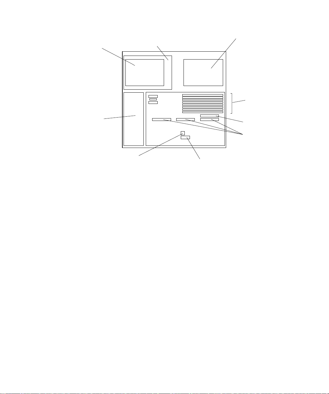
Diskette drive
t
(bottom unit)
CD-ROM drive
(top unit)
Hard drives
(stacked)
DSIMMs
Power
supply
PROM
FIGURE 1-2 Interior View of SPARCstation 5 System
NVRAM
1.1.3 Rear View of SPARCstation 5 System
FIGURE 1-3 shows the rear view of the system.
AFX Bus slo
SBus slots
Chapter 1 Product Description 1-3
Page 22
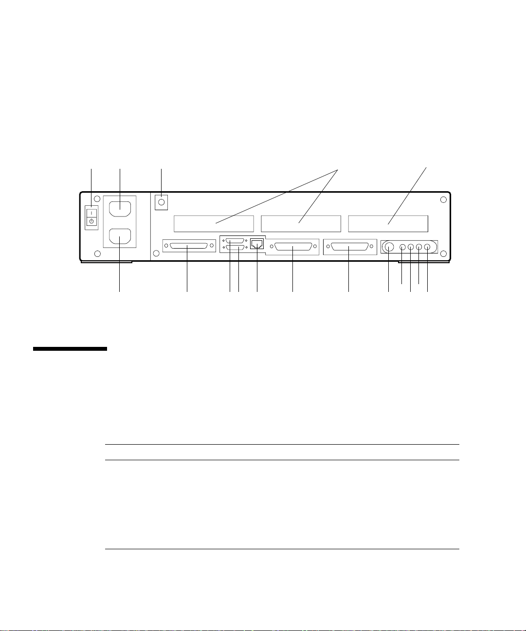
Legend:
1—AC On/Standby switch 7—SCSI 13—Keyboard
2—AC power outlet 8—Parallel 14—Audio, headphone
3—Lock block 9—AUI Ethernet 15—Audio, line-out
4—SBus 10—Twisted-pair Ethernet 16—Audio, line-in
5—SBus or AFX Bus 11—Serial port B 17—Audio, microphone
6—AC power receptacle 12—Serial port A
23 41
687
FIGURE 1-3 Rear View of SPARCstation 5 System
1.2 Internal Options
TABLE 1-1 lists the internal options.
TABLE1-1 Internal Options
5
14
13121110915
16
17
Option Quantity Comments
S24 card 1 Provides accelerated 24-bit color graphics on
SBus cards Up to 3 System board provides up to three SBus slots
Hard disk drives 1 or 2 System supports up to two disk drives of
1-4 SPARCstation 5 Service Manual • August 1994
the system AFX Bus.
for additional system functionality.
varying capacities. See Chapter 9 for more
information.
Page 23

TABLE1-1 Internal Options
Option Quantity Comments
CD-ROM drive 1 Internal CD-ROM drive.
Diskette drive 1 Internal diskette drive for diskette I/O.
DSIMMs Up to 8 System supports up to 256 Mbytes of dynamic
1.3 External Options
TABLE 1-2 lists selected external small computer system interface (SCSI) options.
TABLE1-2 Selected External SCSI Peripheral Options
Unit Description
Desktop Backup Pack 150-Mbyte tape drive or DAT tape drive.
Desktop Disk Pack Disk expansion unit with a variety of SCSI disk drive
capacities.
Desktop SunCD™ Pack Compact CD-ROM disc drive.
Desktop Storage Module 1.3-Gbyte disk drive or 5.0-Gbyte tape drive.
SCSI Expansion Pedestal Up to seven SCSI disks, compact CD-ROM drive, tape
drive, other non-disk units.
Multi-Disk Pack Desktop enclosure containing a disk array of SCSI disk
drives.
20-Gbyte 4-mm Desktop Tape
Auto-Loader
SCSI Expansion Pedestal Holds up to eight disk drives and two or three
Desktop enclosure containing a tape drive with
multiple magazine cartridges; provides up to 20 Gbytes
of tape backup storage.
removable media in the upper tray. Requires a
minimum of two SCSI controllers if all three trays are
used. You cannot have more than seven SCSI devices
on each SCSI bus.
single in-line memory modules (DSIMMs).
Chapter 1 Product Description 1-5
Page 24

1-6 SPARCstation 5 Service Manual • August 1994
Page 25

CHAPTER
2
Troubleshooting Overview
This chapter describes the factory-defined boot sequence. It also describes the
different types of SPARCstation 5 diagnostic firmware and software tools that are
available to you for troubleshooting; the chapter explains how the tools are related
and when to use them.
2.1 Factory-Defined Boot Mode
The flowcharts in FIGURE 2-1 and FIGURE 2-2 outline the roles played by various
diagnostics during a factory-defined boot operation under the control of the
OpenBoot™ PROM (OBP) firmware.
The following sections describe the relationship between the various diagnostic
tools, and the role each tool plays during the SPARCstation 5 factory-defined boot
sequence. The descriptions in the following sections assume you are using a
graphics monitor to view test results.
FIGURE 2-1 (POST phase) and FIGURE 2-2 (OBP phase) graphically depict the flow
of OBP processing control, after power is switched on. Each figure depicts the
possible paths for processing control, and the switch settings for the factory-defined
boot sequence. By examining the two flowcharts you can see where in the processing
sequence other diagnostic tests are available or are encountered.
2-1
Page 26
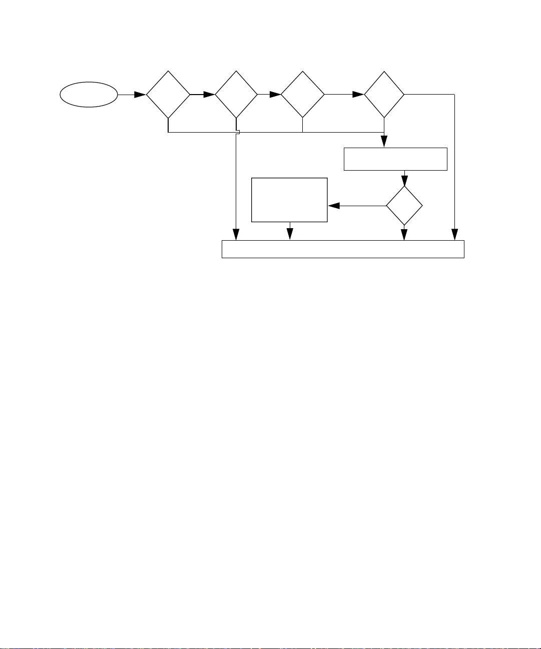
Power-on switch
POST phase
FIGURE 2-1 Factory-Defined Boot Sequence—POST Phase Settings and Tests
If you need to run extended FORTH Diagnostics to take advantage of more extensive
tests, see Appendix D.
Keyboard
attached
?
No
Yes
Stop
key
pressed?
Yes—Skip POST
No
Stop-d
keys
pressed?
Display errors on
keyboard LEDs
and console
OpenBoot PROM firmware takes control
No
Yes—Set
diag-switch? to true
false (default)
diag-
switch?
true
Low-level diagnostic:
POST phase
No
POST
passed
Yes
2-2 SPARCstation 5 Service Manual • August 1994
Page 27
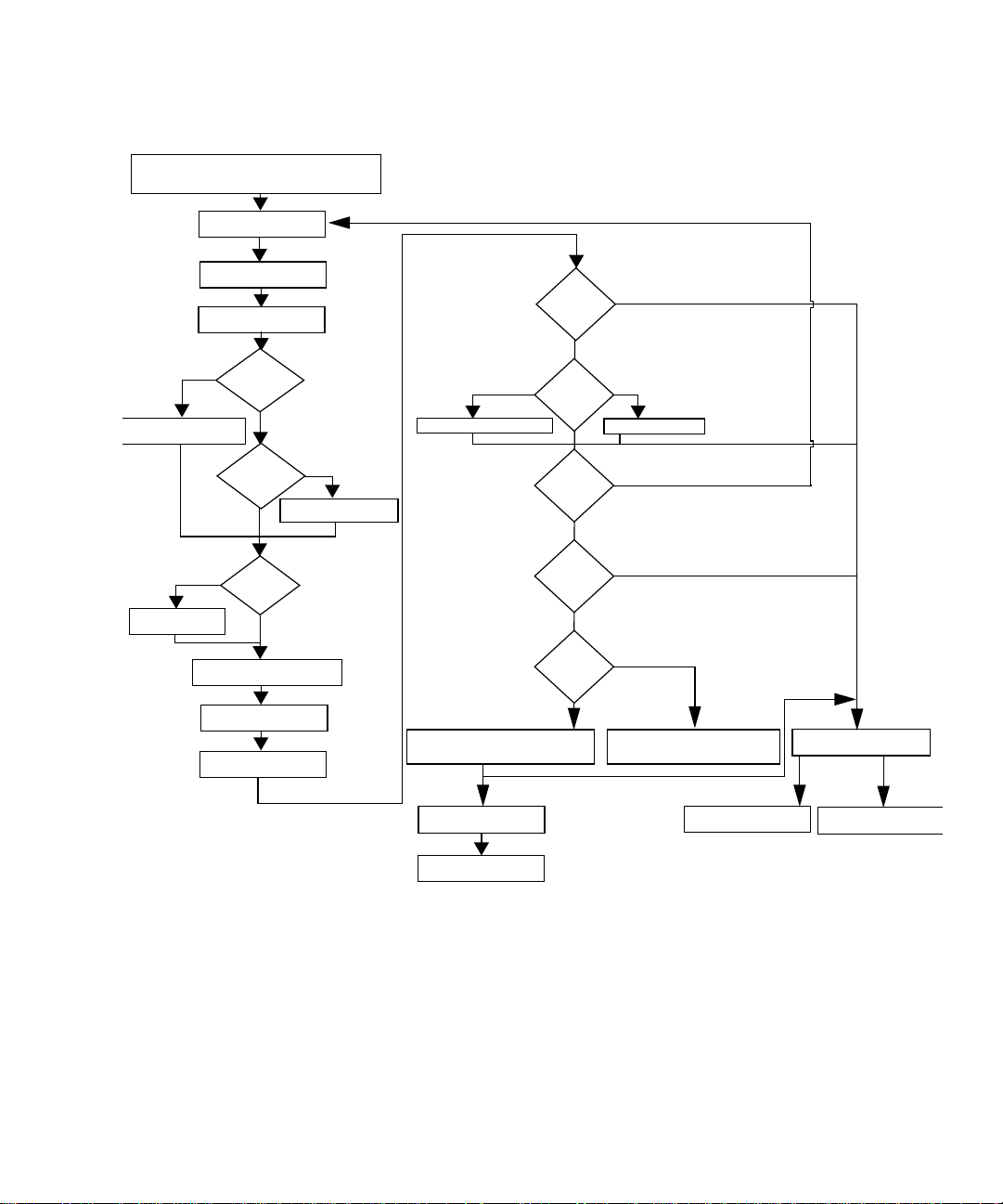
OpenBoot PROM firmware takes control
After POST phase,
System initialization
OpenBoot PROM Phase
Probe memory
Probe CPU
Yes
etting nvram defaults
true
nvramrc?
Evaluate the
script
Probe SBus devices and
interpret their drivers
Install console
System banner
displayed on screen
Stop-n
keys
pressed?
No
Stop-d
keys
pressed?
No
use-
Yes
Set diag-switch?
false
Stop-a
keys
pressed?
No
diag-
false
switch?
Tests selftest-#megs
mfg-
switch?
false
autoboot?
true
diag-
switch?
true
Booting from diag-device=net
and diag-file
Press Stop-a to go to ok prompt
Normal
operating system
Yes
true
Tests all memory
true
false
false
Booting from boot-dev=disk
and boot-file
Press Stop-a
to go to ok prompt
Boot <boot-device>
<boot-file>
ok prompt
On-board
diagnostics
SunDiag System
Exerciser
FIGURE 2-2 Factory-Defined Boot Sequence—OpenBoot PROM Phase Settings and Tests
Chapter 2 Troubleshooting Overview 2-3
Page 28

2.2 After Power Is Switched On
When you turn on the system power, the low-level POST phase is initiated if any of
the following circumstances apply:
■ diag-switch? NVRAM parameter is set to true.
■ Stop-d keys are held down when you turn on the power.
■ Keyboard is disconnected, and diag-switch? is set to false.
The low-level POST code, which is stored in the boot PROM, is designed to test the
most basic functions of the system hardware. The status of the POST is conveyed by
four LEDs on the Sun Type-4, Type-5, and Compact 1 keyboards. The Caps Lock
LED blinks to indicate that the tests are in progress. If a failure is detected during
low-level POST, one of the other three LEDs will light to indicate the nature of the
failure. See Chapter 3 for more information.
Note – You can skip the POST phase by turning on the system while holding down
the Stop key.
At the successful completion of the low-level POST phase, the OpenBoot PROM
firmware takes control and performs the following initialization sequence:
■ Initialize system
■ Probe memory, then CPU
■ Evaluate Script (if use-nvramrc? is set to true)
■ Probe SBus devices and interpret their drivers
■ Install the console (see FIGURE 2-2)
After initialization, a system banner appears on the screen, and the high-level testing
begins. When the high-level tests are finished, the system checks parameters stored
in the NVRAM to determine the next step. Depending on the following parameter
settings, the system will:
■ Boot the operating system from a specified location, if auto-boot?
is set to true
■ Suppress the boot sequence and enter the FORTH Monitor (ok prompt), if auto-
boot? is set to false
■ Continually cycle through the OpenBoot PROM sequence, if mfg-switch? is set
to true
Note – If you are in the Sunmon compatibility mode (prompt is >) type n to return
to the OBP monitor (prompt is ok).
2-4 SPARCstation 5 Service Manual • August 1994
Page 29

TABLE 2-1TABLE 2-1 contains a list of NVRAM parameters and explains their effect
on the power-up sequence. For more detailed information about NVRAM
parameters, see the OpenBoot Command Summary.
Note – At any point during the high-level OBP execution, you can abort the OBP
sequence and access the FORTH Monitor by pressing the Stop and “a” keys
simultaneously.
TABLE2-1 NVRAM Parameters Used During POST and Boot Sequence
NVRAM Parameter Description
selftest-#megs
Default = 1
diag-switch?
Default = false
auto-boot?
Default = true
This parameter determines how many megabytes of
memory to test during high-level OBP testing if diag-
switch? is concurrently set to false. The minimum is
zero; the maximum is the amount actually installed in the
system. The default is a 1-megabyte test.
When set to true, this parameter forces the system to test
automatically all available memory. It also enables
diagnostic message output to serial port A. If a properly
configured terminal or “tip window” is connected,
diagnostic progress can be monitored through this port.
When auto-boot? is set to true and diag-switch? is set
to false, diag-switch? forces the system to boot from
the device and file specified in boot-dev and boot-file.
If auto-boot? is set to true and diag-switch? is set to
true, the system boots the operating system from the
device and file specified in the diag-device and diag-
file NVRAM parameter fields. When set to false, this
will suppress the boot sequence. The system halts with the
ok prompt.
At the FORTH Monitor prompt, you can direct the system to boot the operating
system from a location that you specify, or you can execute a variety of additional
FORTH-based tests. See the OpenBoot Command Reference for a complete description
of the FORTH Monitor.
Chapter 2 Troubleshooting Overview 2-5
Page 30

If the auto-boot? parameter is set to true (the default), the system boots a
standalone program. To determine which program and device to boot from, the
system checks the diag-switch? NVRAM parameter. TABLE 2-2 summarizes the
effect of the auto-boot? and diag-switch? parameters.
TABLE2-2 Summary of Autoboot and Diagnostic Switch Parameter
auto-boot? diag-switch? Result
false false or true > or ok prompt
true false Boot operating system from
device alias “disk” or
“net” for SPARCstation 5
system
true true Boot operating system from
device alias “net”
1. The boot parameters represented here are default settings. The defaults may be changed by following
the procedures listed in the OpenBoot Command Summary.
1
Settings
Once the operating system is running, you can invoke the SunDiag™ System
Exerciser if further diagnostic testing is warranted. Refer to Section 2.7, “SunDiag
System Exerciser,” for additional information.
Another standalone diagnostic program you can run is the SunDiagnostic Executive.
Refer to Section 2.8, “SunDiagnostic Executive,” for further information.
To boot user-specified programs, such as the SunDiagnostic Executive, you must be
at the > prompt or ok prompt. See Appendix D for a detailed procedure on how to
access the > or the ok prompt.
2-6 SPARCstation 5 Service Manual • August 1994
Page 31

2.3 Diagnostic Tools and When to Use Them
TABLE 2-3 provides a summary of the available diagnostic tools and describes when
to use each tool.
TABLE2-3 Diagnostic Tools
Diagnostic Tool When or Why to Use the Tool
Power-On Self-Test
(POST)
FORTH Diagnostics Tests functions such as the Ethernet and SCSI interfaces, system memory, and the
FORTH Monitor Allows input to the system at the boot PROM level. Supports functions such as
SunDiag System Exerciser Runs under the operating system. It displays real-time use of the system
SunDiagnostic Executive Runs extensive, configurable subsystem tests that are independent of the
Executes automatically at power-on when Stop-d keys are pressed or when the
diag-switch? parameter is set to true. The POST code resides in the boot
PROM and is driven by the POK signal from the power supply. POST tells you if
there is a problem with the system board, the NVRAM, or the DSIMMs. See
Section 3.1, “Power-On Self-Test (POST).”
diskette drive controller. You must be at the ok prompt (the FORTH Monitor) to
run the FORTH Diagnostics. The FORTH Diagnostics reside in the boot PROM.
changing NVRAM parameters, resetting the system, running diagnostic tests,
displaying system information, and redirecting input and output. See the
OpenBoot Command Reference for more information.
resources and peripherals. The SunDiag System Exerciser tells you if your
system is functioning correctly. If SunDiag fails, run the Power-On Self-Test. If all
Power-On Self-Tests pass, then run the SunDiagnostic Executive to identify the
problem. See the SunDiag User ’s Guide for more information.
operating system. Run the SunDiagnostic Executive if all tests pass when you
run the POST. Running the SunDiagnostic Executive allows you to determine
which customer replaceable unit needs to be replaced. See the latest version of
SunDiagnostic Executive User’s Guide for the SPARCstations for more information.
2.4 Power-On Self-Test
For information about the POST, see Chapter 3.
Chapter 2 Troubleshooting Overview 2-7
Page 32

2.5 FORTH-Based PROM Diagnostics
For information about how to run the FORTH Diagnostics, see Appendix D.
TABLE 2-4 lists specific on-board diagnostic tests for SPARCstation 5 systems.
TABLE2-4 Selected FORTH Diagnostic Tests
Type of Test Description Preparation When to Use
test screen Tests the system video graphics
hardware and monitor.
test floppy Tests the floppy drive response to
commands.
test scsi Tests the SCSI interface logic on
the system board.
test net-aui Performs an internal and an
external loopback test on the AUI
(Thick) Ethernet interface.
test net-tpe Performs an internal and an
external loopback test on the
twisted-pair Ethernet (TPE)
interface.
test net Performs an internal and an
external loopback test on the
auto-selected system Ethernet
interface.
test disk
test disk0
test disk1
test disk2
test disk3
test cdrom Performs a self-test diagnostic on
Tests internal or external SCSI
disks that have a self-diagnostic
program contained in the drive
controller (disk0 = SCSI address
0, disk1 = SCSI address 1,
disk2 = SCSI address 2, disk
and disk3 = SCSI address 3).
the CD-ROM drive.
The diag-switch? NVRAM
parameter must be set to true.
Insert a formatted diskette into the
drive.
The diag-switch? NVRAM
parameter must be set to true.
A cable must be connected to the
system AUI Ethernet port and to
an Ethernet tap or the test will fail
the external loopback phase.
A cable must be connected to the
system TPE port and to a TPE hub
or the test will fail the external
loopback phase. If the tpe-
link-test? parameter is false
(disabled), the external loopback
test will appear to pass even if a
cable is not connected.
A cable must be attached to the
system and to an Ethernet tap or
hub or the external loopback test
will fail.
The drive must be spinning before
this test is executed or the test will
fail. Enter a boot <disk alias>
command to cause the drive to
spin up.
The CD-ROM must be set to SCSI
target 6 and have a CD inserted in
the drive or the test will fail.
See
description.
See
description.
See
description.
See
description.
See
description.
See
description.
Disk drive
does not
function
properly.
See
description.
2-8 SPARCstation 5 Service Manual • August 1994
Page 33

TABLE2-4 Selected FORTH Diagnostic Tests (Continued)
Type of Test Description Preparation When to Use
test tape
test tape0
test tape1
Tests the SCSI tape drive by
executing the drive self-test
program. tape and tape 0 are
Connect the tape drive to the
system and then turn on the
power.
See
description.
the first tape drive. tape 1 is the
second tape drive.
test ttya
test ttyb
Outputs an alphanumeric test
pattern on the system serial ports
Attach a terminal to the serial port
to observe the output.
Tests serial
ports.
(ttya = serial port A, ttyb =
serial port B).
test keyboard This test executes the keyboard
self- test. The four LEDs on the
Keyboard must be connected. See
description.
keyboard should flash on once,
and the message Keyboard
Present is displayed.
test-memory Tests all of the system main
memory if the diag-switch is
None. See
description.
true.Ifdiag-switch is set to
false, it tests the memory
according to the number
specified in selftest-#megs.
test-all Tests all devices in the system
(such as SBus cards) that have a
built-in test program. Hard disks,
tapes, and
CD-ROMs are not tested.
Set the diag-switch? NVRAM
parameter to true.
When a
device driven
by an SBus
card is not
functioning
properly.
watch-clock Displays seconds from the
system’s Time-of-Day chip.
None. See
description.
watch-net Monitors broadcast Ethernet
packets on the Ethernet cable(s)
connected to the system.
watch-aui Monitors broadcast Ethernet
packets (10Base5—Thicknet) on
the Ethernet cable(s) connected to
the system.
watch-tpe Monitors broadcast Ethernet
packets (10BaseT—Twisted Pair
Ethernet) on the Ethernet cable(s)
connected to the system.
Connect the system to the
network via the desired
Ethernet port.
Connect the system to the
network via the desired
Ethernet port.
Connect the system to the
network via the desired
Ethernet port.
Chapter 2 Troubleshooting Overview 2-9
See
description.
See
description.
See
description.
Page 34

TABLE2-4 Selected FORTH Diagnostic Tests (Continued)
Type of Test Description Preparation When to Use
watch-net-all Monitors broadcast Ethernet
packets on all Ethernet interfaces
installed in the system, one at a
time.
Connect the system to the
network via the desired
Ethernet port.
When an
SBus card
network
controller
card is
installed.
probe-scsi Returns the SCSI devices
(internal and external) and their
SCSI targets connected to the
built-in SCSI port.
Connect external SCSI devices to
the system and turn on
their power.
To determine
if a SCSI
peripheral is
talking to the
system.
To determine
the SCSI
targets
(addresses) of
a SCSI device.
To determine
if more than
one SCSI
peripheral is
assigned the
same SCSI
address.
To determine
if the built-in
SCSI
controller is
defective.
probe-scsi-all Returns to the display the SCSI
devices and their SCSI targets
connected to all SCSI ports (both
the built-in SCSI port and any
additional SCSI host adapter
cards).
Connect external SCSI devices to
the system and turn on
their power.
See probe-
scsi.
To determine
if a SCSI host
adapter
controller is
defective.
power-off Powers off the system. You must have a Sun Type-5
keyboard in order to use this
command.
To power off
the system
with a Sun
Type-5
keyboard.
2-10 SPARCstation 5 Service Manual • August 1994
Page 35

2.6 FORTH Monitor
The FORTH Monitor is a basic diagnostic utility and system interface. If there is any
problem with your operating system, the FORTH Monitor automatically starts, as
indicated by the appearance of the ok prompt (the Monitor also starts if auto-
boot? is set to false).
You can also choose to access the FORTH Monitor by halting the system. For
information on how to access the FORTH Monitor, see Appendix D. For extensive
information about tests you can run from the FORTH Monitor, see OpenBoot
Command Reference.
2.7 SunDiag System Exerciser
Use the SunDiag System Exerciser to determine real-time use of system resources
and peripheral equipment such as Desktop Storage Modules and External Storage
Modules. The SunDiag System Exerciser verifies that the system is functioning
properly. For information about how to use the SunDiag System Exerciser, see the
SunDiag User’s Guide.
If SunDiag passes, the system is operating properly. If SunDiag fails, the error
messages should indicate the part of the system that has failed. If the error messages
are not descriptive enough, you may need to run POST or the SunDiagnostic
Executive.
2.8 SunDiagnostic Executive
The SunDiagnostic Executive is an independent operating system. It runs exhaustive
subsystem tests that are independent of the normal operating system. Run the
SunDiagnostic Executive if all POSTs pass, but your system still has a problem. For
information about POST, see Section 3.1, “Power-On Self-Test (POST).” The
SunDiagnostic Executive is described in the SunDiagnostic Executive User’s Guide for
the SPARCstations.
Chapter 2 Troubleshooting Overview 2-11
Page 36

2-12 SPARCstation 5 Service Manual • August 1994
Page 37

CHAPTER
3
Power-On Self-Test (POST)
This chapter describes the Power-On Self-Test (POST) for Normal, Full, and
Abbreviated modes, available with your SPARCstation 5 system.
The Power-On Self-Test (POST) diagnostics reside in the OpenBoot PROM located
on the system board. There are two POST modes: Normal and Diagnostic.
3.1 Power-On Self-Test (POST)
The Power-On Self-Test (POST) runs when you turn on the system unit power
switch and any of the following conditions apply:
■ diag-switch? NVRAM parameter is set to true.
■ Stop-d keys are held down when you turn on the power.
■ Keyboard is disconnected, and diag-switch? is set to false.
The POST comprises a sequence of tests designed to evaluate the major hardware
components of the main logic board in the short time before the OpenBoot PROM
firmware takes control. The POST does not perform extensive testing on any
component of the main logic board. Only major failures can be detected by the
POST.
Four different LEDs on the keyboards are used to indicate the progress and results of
the POST. These LEDs are on the Caps Lock, Compose, Scroll Lock, and Num Lock
keys, as shown in FIGURE 3-1, FIGURE 3-2, and FIGURE 3-3. To indicate the
beginning of the POSTs, the four LEDs briefly light all at once. The monitor screen
remains blank, and the Caps Lock LED blinks for the duration of the POST.
3-1
Page 38

Scroll Lock LED Num Lock LED
Caps Lock LED
(UNIX Keyboard)
FIGURE 3-1 Arrangement of Sun Type-5 Keyboard Diagnostic LEDs
Caps Lock LED
U.S Keyboard
Caps Lock
LED
FIGURE 3-2 Sun Type-4 Keyboard
Compose
LED
Compose
LED
Scroll Lock
LED
Num Lock
LED
3-2 SPARCstation 5 Service Manual • August 1994
Page 39

Scroll Lock LED
Caps Lock LED
(UNIX Keyboard)
FIGURE 3-3 Sun Compact 1 Keyboard
Caps Lock LED
U.S Keyboard
Compose
LED
Num Lock
LED
If the system fails any POST, one of the LEDs will light to indicate the nature of the
problem. The LED may be lit continuously, or for just a few seconds. TABLE 3-1
provides the meaning of each diagnostic LED.
TABLE3-1 Interpreting the Keyboard Diagnostic LEDs
Diagnostic LED Failed Part
Num Lock LED is lit. Main logic board
Scroll Lock LED is lit. NVRAM
Compose LED is lit DSIMMs (see Section 4.4, “Determining Faulty
DSIMM Locations”)
Note – The Caps Lock LED is not used as a failure indicator; it blinks on and off to
indicate that the POSTs are running. The keyboard LED diagnostics feature
described here applies only to a SPARCstation 5 system with a Sun Type-4, Type-5,
or Compact 1 keyboard connected to its keyboard port. The LED diagnostics do not
apply if a different Sun-supported keyboard is connected to the keyboard port, or if
a terminal and its keyboard are used as a main console instead of a monitor and a
Type-4, Type-5, or Compact 1 keyboard.
Chapter 3 Power-On Self-Test (POST) 3-3
Page 40

If the system passes all the POSTs, all four LEDs light again and then go off. Next,
the OBP firmware performs its initialization sequence and the system banner
appears on the screen. A generic SPARCstation banner is shown as an example.
From this point on, the keyboard LEDs assume their normal functions (that is, you
should no longer interpret the LEDs as diagnostic error indicators).
SPARCstation XXX, Keyboard Present
ROM Rev. X.XY, XX MB memory installed, Serial #XXX
Ethernet address X:X:YY:Z:A:BB, Host ID: XXXXXXXX.
FIGURE 3-4 SPARCstation System Banner
Following the system’s successful initialization, the operating system is booted
automatically—unless the NVRAM configuration options specify otherwise.
You can retrieve more detailed POST failure information by connecting a terminal to
the ttya serial port. If you connect a terminal, you must set the NVRAM parameter
diag-switch? to true. For more information about the NVRAM parameters, see
TABLE 2-1. Test failure messages are displayed on the system monitor or console,
whether or not the system is in Diagnostic Mode. However, it may be easier to
understand the failure message output when it is accompanied by more detailed
POST progress messages available via the ttya serial port.
3.2 Normal Mode
Under Normal Mode, when the system is turned on, control is sent to the OpenBoot
PROM. Depending on the options set in the OpenBoot PROM, for example if auto-
boot? is enabled (set to true), the operating system will load. Diagnostic testing is
not run.
3.3 Full Diagnostic Mode
Full Diagnostic Mode tests the major hardware system board components and, if the
POST is successful, control is transferred to the OBP firmware that probes the
installed SBus modules. Full Diagnostic Mode runs if one of these conditions is met:
■ You press and hold the Stop-d keys while you turn on the power.
3-4 SPARCstation 5 Service Manual • August 1994
Page 41

■ You set the diag-switch? NVRAM parameter to true in the OpenBoot PROM.
■ You disconnect the keyboard and you set the diag-switch? NVRAM parameter
to true in the OpenBoot PROM.
Note – POST does not perform extensive testing on any system board component.
POST detects only major failures.
To view error messages returned by POST, connect a terminal to serial port A or use
a tip connection to another workstation.
If you do not connect a terminal to serial port A or use a tip connection, the screen
will be blank during the POST diagnostics. In this case, use the keyboard LEDs to
display error conditions. See Section 3.7, “Status Lights (LEDs) and Indicators.”
3.4 Abbreviated Diagnostic Mode
A silent Power-On Self-Test (POST) is run if you disconnect the keyboard and you
set the diag-switch? NVRAM parameter to false in the OpenBoot PROM. This
Power-On Self-Test is silent (no progressive test messages are printed out). If an
error or errors occur during the abbreviated Power-On Self-Test, all error messages
are displayed on the TTY or tip window.
3.4.1 Setting Up a tip Connection to Another System
You can use the serial port on your SPARCstation 5 system to connect to another Sun
workstation (either the same type of SPARC“ system or a different type of Sun
workstation or server system). This connection lets you use a shell window on the
Sun workstation as a terminal to the SPARCstation 5 being tested.
The tip method is recommended, because it lets you use SunOS™ windowing and
operating system features to help you work with the boot PROM.
To make a tip connection, follow these steps:
1. Connect the system’s serial port ( ttya) to another Sun workstation ttya serial
port using a serial connection cable. This connection is made with a 3-wire null
modem cable. Connect wires 3-2, 2-3, and 7-7.
Chapter 3 Power-On Self-Test (POST) 3-5
Page 42

2. At the other Sun workstation, add the following lines to the file /etc/remote:
hardware:\
:dv=/dev/ttya:br#9600:el=^C^S^Q^U^D:ie=%$:oe=^D:
3. In a Shell Tool window on the Sun workstation, type tip hardwire. (Some
commands will not work properly in a Command Tool window.)
The system will reply connected.
hostname% tip hardwire
connected
The Shell Tool window is now a tip window directed to the Sun workstation serial
port.
4. When you are finished running POST and want to disconnect the tip window,
either type ~. (tilde period) in the tip window, or type kill -9 and the process
ID number of the tip hardwire process.
hostname% ~.
or
hostname% kill -9 PID# of tip hardwire process
3.5 Tests the POST Runs
Following is a sample listing of the Full Diagnostic Mode tests completed by POST.
CODE EXAMPLE 3-1 POST Tests
MMU Context Table Reg Test
MMU Context Register Test
MMU TLB Replace Ctrl Reg Tst
MMU Sync Fault Stat Reg Test
MMU Sync Fault Addr Reg Test
MMU TLB RAM NTA Pattern Test
MMU TLB CAM NTA Pattern Test
MMU TLB LCAM NTA Pattern Test
IOMMU SBUS Config Regs Test
IOMMU Control Reg Test
IOMMU Base Address Reg Test
3-6 SPARCstation 5 Service Manual • August 1994
Page 43

CODE EXAMPLE 3-1 POST Tests
IOMMU TLB Flush Entry Test
IOMMU TLB Flush All Test
SBus Read Time-out Test
EBus Read Time-out Test
D-Cache RAM NTA Test
D-Cache TAG NTA Test
I-Cache RAM NTA Test
I-Cache TAG NTA Test
Memory Address Pattern Test
FPU Register File Test
FPU Misaligned Reg Pair Test
FPU Single-precision Tests
FPU Double-precision Tests
FPU SP Invalid CEXC Test
FPU SP Overflow CEXC Test
FPU SP Divide-by-0 CEXC Test
FPU SP Inexact CEXC Test
FPU SP Trap Priority > Test
FPU SP Trap Priority < Test
FPU DP Invalid CEXC Test
FPU DP Overflow CEXC Test
FPU DP Divide-by-0 CEXC Test
FPU DP Inexact CEXC Test
FPU DP Trap Priority > Test
FPU DP Trap Priority < Test
PROC0 Interrupt Regs Tests
Soft Interrupts OFF Test
Soft Interrupts ON Test
PROC0 User Timer Test
PROC0 Counter/Timer Test
DMA2 E_CSR Register Test
LANCE Address Port Tests
LANCE Data Port Tests
DMA2 D_CSR Register Test
DMA2 D_ADDR Register Test
DMA2 D_BCNT Register Test
DMA2 D_NADDR Register Test
ESP Registers Tests
DMA2 P_CSR Register Test
DMA2 P_ADDR Register Test
DMA2 P_BCNT Register Test
PPORT Registers Tests
NVRAM Access Test
TOD Registers Test
Chapter 3 Power-On Self-Test (POST) 3-7
Page 44

3.6 POST Error Messages
The POST error messages returned to the terminal are self-explanatory. For example,
if no DSIMM is installed in the system, the POST will tell you that no DSIMM is
installed and will indicate the slot number of the DSIMM slot. Use the error
messages returned by POST to troubleshoot the system.
3.7 Status Lights (LEDs) and Indicators
The LED at the front of the chassis lights when the system is operating normally.
FIGURE 3-5 shows the location of the system LED. Chapter 4, “ shows flow
diagrams of actions to take when the system LED is not lit.
System Front
FIGURE 3-5 Location of System Power LED
Section 3.1, “Power-On Self-Test (POST), describes the keyboard LED sequences
displayed at power up when POST fails. If a failure occurs in POST, the keyboard
displays a specific LED pattern. See FIGURE 3-1 through FIGURE 3-3 and
TABLE 3-1. During normal system operation, the LEDs should not be interpreted as
diagnostic error indicators.
3-8 SPARCstation 5 Service Manual • August 1994
System Power LED
Page 45

Following the system initialization, the operating system boots automatically, unless
the NVRAM configuration options specify not to do so.
Note – The Caps Lock key LED on some U.S. keyboards, located just above the left-
hand Shift key, is not used as a POST failure indicator, but blinks on and off while
POST is running.
If the Caps Lock key fails to flash on and off after you have pressed and held the
Stop-d keys when you power on the system, POST failed. See Section 4.2.2, “System
Board Test,” for troubleshooting information.
Chapter 3 Power-On Self-Test (POST) 3-9
Page 46

3-10 SPARCstation 5 Service Manual • August 1994
Page 47

CHAPTER
4
Troubleshooting Procedures
This chapter describes how to troubleshoot SPARCstation 5 system problems. Each
problem is described, and a set of procedures is provided as a solution to the
problem.
TABLE 4-1 describes commonly encountered problems, and tips for solving them.
TABLE4-1 Troubleshooting Tips
Problem Action
LED on front of system is not lit. Verify that the power switch is turned on and that the power cord is
connected. If both the power switch and the power cord are connected,
shut down the system and verify that the LED cable is connected. If the
LED cable is connected, the power supply may be defective. Replace the
power supply. See Chapter 8.
Disk drive fails to boot or does not
respond.
Operating system does not
recognize disk drive at boot up.
No video output on monitor. Verify that the power cord is connected. Use a volt-ohmmeter (VOM) to
Slow disk drive response. If many SCSI devices are connected to the same SCSI bus and if some of
Shut down the system. The SCSI controller may be defective. See
Section 4.3.1, “Verifying the Built-In SCSI Controller.” Verify that each
SCSI device is assigned a unique SCSI target address. See Appendix C for
important additional information.
Shut down the system. Verify that each SCSI device is assigned a unique
SCSI target address. See Appendix C for important additional
information.
check voltages. See Section 4.1, “No Video Output on the System
Monitor.”
these devices are “fast SCSI” devices, you can install an FSBE/S SBus
card to the “fast SCSI” devices to speed up performance.
4-1
Page 48

TABLE4-1 Troubleshooting Tips
Problem Action
Read, write, or parity error
reported by the operating system
or applications.
Power on does not succeed. LEDs
on keyboard do not light and
there is no tone from the keyboard
when you turn on the system
power.
Power on does not succeed. The
system fails to initialize but the
LEDs on the keyboard light and
there is a tone from the keyboard.
Replace the disk drive indicated by the failure message. Solaris 1.x
operating systems identify the disk drive installed in the lower bay (SCSI
target ID 3) as sd0 and the disk drive installed in the upper bay (SCSI
target ID 1) as sd1. With Solaris 2.x operating systems, the two drives are
identified as c0t3d0 and c0t1d0, respectively.
The power supply may be defective. See Section 4.2.1, “Power Supply
Test.”
The system board may be defective. See Section 4.2.2, “System Board
Test.”
4.1 No Video Output on the System Monitor
1. Check that the power cord is connected to the monitor and to the wall outlet.
2. Verify that the wall outlet is supplying AC power to the monitor.
Use a volt-ohmmeter (VOM).
3. Verify that the video cable connection is secure between the monitor and the
system video output port.
Use a VOM to perform the continuity test on the video cable.
If the power cord and video cable connection are good and there is still no video
output, reseat the video card for the monitor.
4. If the monitor power supply is internally fused, check the fuse.
The fuse could be blown.
4.2 Power-On Does Not Succeed
1. Turn off the system power switch.
4-2 SPARCstation 5 Service Manual • August 1994
Page 49

2. Check that the system power cord is properly connected to the system rear panel
power receptacle and to the wall outlet.
3. Verify with a VOM that the wall outlet is supplying AC power to the system.
4. Turn the rear panel system power switch on and observe the keyboard.
The LEDs on the keyboard should briefly light. You should hear a tone from the
keyboard. If you have a Sun Type-5 keyboard, there is a Standby power key which
you may also press to see if the system can be powered on or not. Only try the
Standby power key if the rear switch fails to turn on the system.
If you hear no tone or see no lights on the keyboard, the system’s power supply may
be defective. See Section 4.2.1, “Power Supply Test.”
If you hear a tone and see lights on the keyboard, but the system still fails to
initialize, see Section 4.2.2, “System Board Test.“
4.2.1 Power Supply Test
1. Use a VOM (volt-ohmmeter) to check the power supply output voltages.
Place the VOM negative probe on one of the logic ground pins in the connector, and
test the +12V, -12V, and +5V power pins individually with the positive probe (pins 1
through 8). See FIGURE 4-1 and TABLE 4-2.
Note – The power supply must remain connected to the system board during this
test. This allows the power supply to regulate the voltages.
2. Replace the power supply assembly if any of the voltages are not present.
See Section 8.1, “Power Supply.”
Chapter 4 Troubleshooting Procedures 4-3
Page 50

19
2
3456 87
10 18
11 1314 1612 15 17
FIGURE 4-1 Power Supply Connector
TABLE 4-2 shows the pin assignments on the power supply connector.
TABLE4-2 Power Supply Connector Pin Assignments
Pin Color Description
1 Blue +12V 10 Black Ground
2 Brown -12V 11 Black Ground
3 Red +5V 12 Black Ground
4 Red +5V 13 Black Ground
5 Red +5V 14 Black Ground
6 Red +5V 15 Black Ground
7 Red +5V 16 Green AC Outlet
8 Red +5V 17 Purple Fan
9 Grey Power off 18 Yellow Power on
1. All volts are direct current.
1
Pin Color Description
4-4 SPARCstation 5 Service Manual • August 1994
Page 51

4.2.2 System Board Test
1. Connect a terminal to serial port A or use a tip connection to another workstation
to receive additional POST failure information.
To set up a tip connection to another workstation, see Section 3.4.1, “Setting Up a
tip Connection to Another System.”
2. Press and hold the Stop-d keys. While holding the keys down, turn the system
power switch on. Watch the keyboard LEDs.
a. The Caps Lock key on the keyboard should flash on and off, indicating that the
system is running the Power-On Self-Test (POST).
If the Caps Lock key fails to flash on and off after you have pressed and held the
Stop-d keys, POST failed.
b. To further troubleshoot the system board, see Section 4.2.2.1, “Caps Lock Key
Fails to Flash On and Off During POST.”
3. Observe the keyboard LEDs.
If a failure occurs during POST, an LED may light up. See TABLE 3-1 on page 3 to
interpret the keyboard diagnostic LEDs.
4. Replace the defective part indicated.
4.2.2.1 Caps Lock Key Fails to Flash On and Off During POST
1. Remove optional SBus cards and DSIMMs.
Leave one DSIMM in Slot 0 (J0300).
2. Run POST again before replacing the system board.
Remove all other parts to eliminate the possibility that those parts could be causing
the POST failure.
Chapter 4 Troubleshooting Procedures 4-5
Page 52

4.3 Disk Drive Errors
TABLE 4-3 presents disk drive error conditions and corrective actions.
TABLE4-3 Troubleshooting Disk Drive Errors
Symptom Corrective Action
Read, write, or parity error
reported by the operating system
or applications.
Drive fails to boot or does not
respond to commands.
Slow disk drive response. If many SCSI devices are connected to the same SCSI
Replace the disk drive indicated by the failure
message. Solaris 1.x operating systems identify the
disk drive installed in the lower bay (SCSI target ID 3)
as sd0 and the disk drive installed in the upper bay
(SCSI target ID 1) as sd1. With Solaris 2.x operating
systems, the two drives are identified as c0t3d0 and
c0t1d0, respectively.
SCSI controller may be defective. See Section 4.3.1,
“Verifying the Built-In SCSI Controller.” Verify that
each SCSI device is assigned a unique SCSI target
address. See Appendix C for important additional
information.
bus and if some of these devices, such as the 1.05Gbyte disk drive, are “fast SCSI” devices, you may
want to install an FSBE/S SCSI host adapter card to
the “fast SCSI” devices and put these “fast SCSI”
devices on a separate SCSI bus to speed up disk drive
response.
4.3.1 Verifying the Built-In SCSI Controller
To check whether the built-in SCSI controller is defective, test the drive response to
the probe-scsi command. To test additional SCSI host adapters added to the
system, use the probe-scsi-all command. Refer to Section D.1.6, “module-info.”
4-6 SPARCstation 5 Service Manual • August 1994
Page 53

● At the ok prompt, type probe-scsi
See the following example.
ok probe-scsi
Target 1
Unit 0 Disk CONNER CP30548 SUN0535AEBX93081QTT
Target 3
Unit 0 Disk SEAGATE ST3610N SUN0535881200054301
a. If the disk drive responds and a message is displayed, the system SCSI
controller has successfully probed the devices.
This indicates that the system board is working correctly.
b. If a disk doesn’t respond:
c. Make sure that every SCSI disk and other SCSI device on the SCSI bus has a
different SCSI target ID (see Appendix C).
Note – Internal SCSI hard drives are automatically assigned target 3 (lower bay)
and target 1 (upper bay).
d. Verify that all SCSI cables and the SCSI terminator are connected securely.
e. Check the SCSI cables to make sure there are no bent pins.
f. If you still have not found the problem, replace the unresponsive drive.
g. If the problem still occurs after replacing the drive, replace the system board.
h. If the problem persists, replace the internal disk drive cable assembly.
4.4 Determining Faulty DSIMM Locations
The SunDiag System Exerciser, SunDiagnostic Executive, and POST diagnostics can
report memory errors encountered during program execution. For general
information about diagnostics, see Chapter 2, “Troubleshooting Overview.” Memory
error messages on the video monitor usually indicate a physical memory address
where the error was detected.
Depending on the diagnostic program you are running, a DSIMM location number
(“J” number) or a memory address may be displayed.
Chapter 4 Troubleshooting Procedures 4-7
Page 54

If the error message displays the location number, see FIGURE 4-2 for DSIMM
location numbers. If the error message displays a physical memory address, consult
TABLE 4-4 to see which memory slot contains the physical address.
For example, if an error is detected at physical memory address 12fe958, examining
TABLE 4-4 shows that the error occurred in the DSIMM in slot 0.
After you have identified the defective DSIMM, follow the instructions in
Section 11.3.1, “Removing a DSIMM, for removing the defective DSIMM. To replace
the DSIMM, follow the directions in Section 11.3.2, “Replacing a DSIMM.
SIMM slot J0403 Slot 7
SIMM slot J0402
SIMM slot J0401
SIMM slot J0400
SIMM slot J0303
SIMM slot J0302
SIMM slot J0301
Slot 6
Slot 5
Slot 4
Slot 3
Slot 2
Slot 1
SIMM slot J0300 Slot 0
FIGURE 4-2 DSIMM Slot Locations
TABLE4-4 Physical Memory Address Ranges for Slots
Slot SIMM # Physical Memory Address Rang es
0 J0300 0000 0000 through 01FF FFFF
1 J0301 0200 0000 through 03FF FFFF
2 J0302 0400 0000 through 05FF FFFF
3 J0303 0600 0000 through 07FF FFFF
4 J0400 0800 0000 through 09FF FFFF
5 J0401 0A00 0000 through 0BFF FFFF
6 J0402 0C00 0000 through 0DFF FFFF
7 J0403 0E00 0000 through 0FFF FFFF
1. Each memory slot can contain one DSIMM up to 32 megabytes in size. Slot 0 must have a DSIMM present.
4-8 SPARCstation 5 Service Manual • August 1994
1
0 Through 7
Page 55

CHAPTER
5
Safety and Tools Requirements
This chapter describes standards, safety procedures, and precautions you should
follow whenever you need to replace or remove assemblies or subassemblies from
your system.
5.1 Safety Requirements
For your protection, observe the following safety requirements:
■ Follow all cautions, warnings, and instructions marked on the equipment.
■ Ensure that the voltage and frequency rating of the power outlet matches the
electrical rating labels on the system.
■ Use properly grounded power outlets.
5-1
Page 56

To protect both yourself and the equipment, observe the safety precautions listed in
TABLE 5-1.
TABLE5-1 Safety Precautions
Item Problem Precaution
AC power cord Electric shock Unplug the AC cord from the AC wall socket
before working on the power supply.
Grounding Leave the AC power cord plugged into the AC
wall outlet when replacing drives, DSIMMs,
chips, or the system board. Leaving the AC
power cord plugged into the wall outlet
provides a grounding path for the wrist strap,
which must be attached.
Wrist strap Electrostatic
Discharge (ESD)
ESD mat ESD An approved antistatic mat provides protection
Printed circuit
boards
Cover System damage
SBus slot filler
panels
microSPARC chip
heat sink
ESD Handle a printed circuit board by the edges
and overheating
System damage
and overheating
Heat, burns Do not touch the metal heat sink on the
Wear a wrist strap when handling printed
circuit boards, drives, or other components
such as DSIMMs.
from static damage when used with a wrist
strap. The mat also cushions and protects small
parts that are attached to printed circuit boards.
Chapter 12, “,” lists the part number of the mat.
only. Store a board in an antistatic bag.
Replace the cover after performing service on
the system.
Install filler panels in all unused SBus
openings. Openings on the back of the system
board reduce the cooling capability of the
system.
microSPARC chip. The heat sink can be hot
enough to cause personal injury.
5.2 Symbols
The following symbols mean:
5-2 SPARCstation 5 Service Manual • August 1994
Page 57

Caution – This equipment contains lethal voltages. Accidental contact can result in
serious injury or death.
Caution – Physical danger due to a non-electrical hazard or danger of irreversible
damage to data or to the operating system.
Caution – Improper handling by unqualified personnel can cause serious damage
to this equipment. Unqualified personnel who tamper with this equipment may be
held liable for any resulting damage to the equipment.
Caution – Hot surface. Avoid contact. Surfaces are hot and may cause personal
injury if touched.
ACA terminal (power outlet) to which alternating current or voltage may be
applied.
ONThe power switch is in the ON position.
STANDBYThe power switch is in the STANDBY position.
5.3 System Precautions
Individuals who service this equipment must observe all safety precautions and
ensure compliance with skill level requirements, certification, and all applicable local
and national laws.
Procedures contained in this document must be performed by trained maintenance
providers. Only people who have been trained at the Sun Microsystems® training
facilities (or at Sun Microsystems affiliates) and have been certified as required by
local and national laws are considered qualified.
Chapter 5 Safety and Tools Requirements 5-3
Page 58

Caution – Before you begin, carefully read each of the procedures in this manual. If
you have not performed similar operations on comparable equipment, do not attempt
to perform these procedures.
5.4 Tools Required
To remove and replace customer replaceable units (CRUs), you will need the
following tools and materials:
■ Small Phillips-head screwdriver
■ Small flat-blade screwdriver
■ Wrist strap
■ Antistatic surface
■ Volt-ohmmeter (VOM) for checking voltages and continuity
■ Needlenose pliers
■ Conductive foam to store chips
■ Container for screws
5.5 Electrostatic Discharge (ESD) Precautions
Caution – The system chassis power must be turned off, and the AC power cord
must remain plugged in to ensure a proper ground.
To minimize electrostatic discharge, observe the following precautions:
■ Hold the system board, SBus cards, DSIMMs, or system components only by the
edges.
■ When removing a board, card, or module from an antistatic bag, lay it on an
antistatic surface such as a Sun ESD mat, an antistatic bag, or a disposable
antistatic mat.
■ Do not place the boards, cards, or modules on an unprotected surface. Use a
cushioned antistatic mat or antistatic bag. Connectors and components have very
thin pins that bend easily.
■ Do not use an oscilloscope or VOM (volt-ohmmeter) probe on the components.
The soldered pins are easily damaged or shorted by the probe point.
5-4 SPARCstation 5 Service Manual • August 1994
Page 59

■ Transport boards, cards, or modules in an antistatic bag.
■ Always wear an antistatic wrist strap connected to a metal surface on the chassis
when working on system components and parts.
Chapter 5 Safety and Tools Requirements 5-5
Page 60

5-6 SPARCstation 5 Service Manual • August 1994
Page 61

CHAPTER
6
Power On and Off
This chapter explains steps to perform before removing a customer replaceable unit
(CRU).
6.1 Powering Off the System
Before you begin any removal or replacement procedure, you must halt the system
in an orderly manner. The procedure to use depends on whether your system is
working normally or not, as described in the next sections.
Caution – When the operating system or any other standalone program has already
booted, do not use the Stop-a keys to halt the system. Using the Stop-a keys to abort
program execution can damage data files.
6.1.1 When the System Is Working Normally
To halt your system when it is working normally:
1. Save all your work.
Consult your software documentation for instructions on ending a work session and
saving your files. If you do not save your work, you could lose it when you switch
off the power.
2. Return to the operating system environment.
If you are in a windowing environment, exit from it and wait for the system prompt
to appear. See the documentation supplied with your windowing system.
6-1
Page 62

3. Halt the operating system.
See the documentation supplied with your operating system for instructions on how
to halt it.
a. For Solaris® 2.x (SunOS 5.x) systems, type:
% su
Password: superuser password
# /usr/sbin/shutdown -y -g60 -i0
b. For Solaris 1.x (SunOS 4.x) systems, type:
% su
Password: superuser password
# /usr/etc/shutdown -h +1
The operating system warns other users of your system of the impending
shutdown, and then halts itself after a one-minute delay. If you wish to provide a
longer delay, see the man page for shutdown(1).
The system responds with system halt messages followed by an ok prompt. When
the ok prompt appears, you can safely turn off the power in the proper sequence.
4. When the ok prompt appears, turn off the power to the system components in this order:
1. External drive units (if you have any)
2. System unit
3. Monitor
6.1.2 When the System Does Not Respond Normally
To halt a system that is hung, or frozen, and unresponsive to commands:
1. If your system is on a network, wait a few minutes before proceeding.
Your system’s slow response may be due to network problems or delays. Check with
the person in charge of your network. If the response is not due to the network, go
to the next step.
2. Press Stop-a (or Break).
If you use a Wyse® WY-50™, VT-100™, or compatible terminal as the console with
your SPARCstation 5 system unit, press Break instead of Stop-a.
6-2 SPARCstation 5 Service Manual • August 1994
Page 63

Note – If the system does not respond to the mouse and keyboard, pressing Stop-a
will not be effective. You may have to turn the power off, wait at least 10 seconds,
and turn the power on again. Then try pressing Stop-a once more.
3. When the ok prompt appears, boot the operating system.
Enter boot at the ok prompt.
4. When you see the login prompt, log in to the system with your user name and password.
5. Halt the operating system.
See the documentation supplied with your operating system for instructions on how
to halt it.
a. For Solaris 2.x (SunOS 5.x) systems, type:
% su
Password: superuser password
# /usr/sbin/shutdown -y -g60 -i0
b. For Solaris 1.x (SunOS 4.x) systems, type:
% su
Password: superuser password
# /usr/etc/shutdown -h +1
The operating system warns other users of your system of the impending
shutdown, and then halts itself after a one-minute delay. If you wish to provide a
longer delay, see the man page for shutdown(1).
The system responds with system halt messages followed by an ok prompt. When
the ok prompt appears, you can safely turn off the power in the proper sequence.
c. When the ok prompt appears, turn off the power to the system components in
this order:
1. External drive units (if you have any)
2. System unit
3. Monitor
Chapter 6 Power On and Off 6-3
Page 64

6.2 Powering On the System
Caution – Before turning on power to your system, be sure to close the system unit.
It is not safe to operate your SPARCstation while the system unit is open.
Caution – These devices are equipped with a three-wire grounded power cord. To
reduce the risk of electrical shock, always plug the power cord into a properly
grounded power outlet.
Caution – Always allow 10 seconds between turning off the power and turning it
back on again. This pause prevents possible damage to power supply components in
your system unit.
To turn on power to the SPARCstation 5 system:
1. If your system uses external drive units, turn on the power to these units first,
starting with the unit that is furthest electrically from the system unit.
2. Turn on the power to the monitor.
3. Turn on the power to the system unit.
6-4 SPARCstation 5 Service Manual • August 1994
Page 65

CHAPTER
7
Internal Access
This chapter describes how to access the subassemblies inside the system unit, and
how to close the system unit after you have finished.
7.1 Removing the Cover
Caution – The AC power cord should remain attached between the system unit and
an AC wall outlet. This connection provides the ground path necessary to protect
internal system components from harmful static discharges. Inside the system unit,
be sure the power supply wiring harness is connected to the main logic board to
complete the ground.
Caution – The surface of the microSPARC™ II chip may be hot and could cause
personal injury if touched. Avoid contacting this component.
Caution – Before opening the system unit, make sure the system power is in the
Standby mode. The LED on the front of the system unit should not be lit, and the
fans should not be running.
Caution – When the system power switch is in the Standby position, and the AC
power cord remains connected to a power outlet, hazardous AC voltage is still
present in the power supply primary. Do not attempt to service the power supply
under these conditions. Disconnect the AC power cord prior to handling the power
supply. When servicing any other system component, the AC power cord should
remain connected; it poses no safety hazard.
7-1
Page 66

1. Press the Standby side of the system power switch.
2. Loosen the captive Phillips-head screw in the upper-right corner of the rear panel
(see FIGURE 7-1).
3. Unscrew the Phillips-head screw that secures the lock block to the cover. Remove
the lock block and put it aside (see FIGURE 7-1).
FIGURE 7-1 Removing the Rear Panel Cover Screws
4. Lift the cover free of the chassis as shown in FIGURE 7-2.
7-2 SPARCstation 5 Service Manual • August 1994
Page 67

FIGURE 7-2 Removing the Cover
5. Attach a wrist strap to your wrist and to the metal casing of the power supply.
See Section 7.2, “Attaching the Wrist Strap.”
Caution – When you are finished servicing parts inside the system unit, be sure to
close the system unit before turning on the power. It is not safe to operate the system
unit while it is open.
7.2 Attaching the Wrist Strap
1. Unwrap the first two folds of the wrist strap and wrap the adhesive side securely
around your wrist.
See FIGURE 7-3.
Chapter 7 Internal Access 7-3
Page 68

FIGURE 7-3 Grounding the Wrist Strap to the Power Supply
2. Peel the liner from the copper foil at the opposite end of the wrist strap and attach
that end to the top of the power supply.
Make sure that the strap makes good contact with the metal casing of the power
supply; avoid the labels on top of the supply. See FIGURE 7-3.
7.3 Replacing the Cover
1. Remove the wrist strap from your wrist and then from the power supply.
2. Align the cover hinge tabs with the tab slots on the bottom front of the system
chassis. Carefully lower the cover, making sure the hinge hooks remain inside
their respective slots.
7-4 SPARCstation 5 Service Manual • August 1994
Page 69

Guide cover hinge hooks
into corresponding slots
in front of system chassis.
FIGURE 7-4 Replacing the Cover
3. Replace the lock block on the rear panel. Tighten the Phillips-head screw that
secures the lock block to the cover.
See FIGURE 7-5.
4. Tighten the captive Phillips-head screw in the upper-right corner of the rear panel.
See FIGURE 7-5.
Chapter 7 Internal Access 7-5
Page 70

Caution – Do not use a power driver to tighten captive screws. Do not overtighten
captive screws.
FIGURE 7-5 Securing the System Unit Cover
7-6 SPARCstation 5 Service Manual • August 1994
Page 71

CHAPTER
8
Major Subassemblies
This chapter describes how to remove and replace the system unit’s major
subassemblies.
8.1 Power Supply
Caution – When the system power switch is in the Standby position, and the AC
power cord remains connected to a power outlet, hazardous AC voltage is still
present in the power supply primary. Do not attempt to service the power supply
under these conditions. Disconnect the AC power cord prior to handling the power
supply. When servicing any other system component, the AC power cord should
remain connected; it poses no safety hazard.
8.1.1 Removing the Power Supply
Caution – To avoid damage to the system board or components, press the Standby
side of the AC power switch before disconnecting the external power cord from the
rear panel. The SPARCstation 5 power supply “remembers” the state it was in when
the power cord was detached, and it will automatically return to that state when the
power cord is reconnected.
1. Shut down and power off the system.
See Section 6.1, “Powering Off the System.”
2. Disconnect the external power cord from the rear panel of the system unit and
from the wall outlet.
8-1
Page 72

3. Remove the cover.
See Section 7.1, “Removing the Cover.”
4. Attach a wrist strap and secure it to the upper flat edge of the rear panel.
SeeFIGURE 8-1 .
Note – The wrist strap is usually grounded to the power supply. When removing or
replacing the power supply, attach the wrist strap to the upper flat edge of the rear
panel to ground the system.
5. On the rear panel, loosen the captive screw(s) securing the power supply to the chassis.
Some models have two captive screws, others have one. See FIGURE 8-1.
Power supply
Captive screws
(some models
have only one)
Power supply
connector
FIGURE 8-1 Removing the Power Supply
Power supply
rear view
DC power
harness
DC power
connector
6. Disconnect the power supply connector from the system board.
See FIGURE 8-1.
8-2 SPARCstation 5 Service Manual • August 1994
Page 73

7. Slide the power supply toward the chassis front to free it from the chassis mounts.
See FIGURE 8-1.
8. Lift the power supply out of the chassis and disconnect the DC power harness
from the keyed connector on the rear of the power supply.
See FIGURE 8-2.
8.1.2 Replacing the Power Supply
1. Attach a wrist strap and secure it to the rear panel.
See FIGURE 8-1.
Note – The wrist strap is usually grounded to the power supply. However, when
removing or replacing the power supply, attach the wrist strap to the upper flat edge
of the backpanel to ground the system.
2. Hold the power supply in one hand. Connect the DC power harness to the rear of the power supply.
See FIGURE 8-2.
Power supply
rear view
DC power harness
Power
supply
connector
FIGURE 8-2 Connecting the DC Power Harness to the Power Supply
3. Lower the power supply into the chassis at an angle, so that the DC power
connector fits under the peripheral bracket.
4. Slide the power supply toward the rear of the chassis until it locks in the power supply mounts.
Chapter 8 Major Subassemblies 8-3
Page 74

5. Tighten the captive screw(s) to secure the power supply to the rear of the chassis.
See FIGURE 8-1.
Caution – Do not use a power driver to tighten a captive screw. Do not overtighten
a captive screw.
6. Plug the power supply connector into the system board.
See FIGURE 8-1.
7. Remove the wrist strap from your wrist and then from the power supply.
8. Replace the cover.
See Section 7.3, “Replacing the Cover.”
9. Plug in the power cord to the system unit and the wall outlet.
10. Power on the system.
See Section 6.2, “Powering On the System.”
8.2 Power LED
The system power LED is located at one end of the speaker/LED cable. An in-line
connector in the cable facilitates removal of the LED without having to remove the
entire speaker/LED cable.
8.2.1 Removing the Power LED
1. Shut down and power off the system.
See Section 6.1, “Powering Off the System.”
2. Remove the cover and attach a wrist strap.
See Chapter 7.
3. Remove the CD-ROM drive (if present).
See Section 9.2.1, “Removing the CD-ROM Drive.”
4. Disconnect the in-line connector in the speaker/LED cable.
See FIGURE 8-3.
8-4 SPARCstation 5 Service Manual • August 1994
Page 75

Power LED
FIGURE 8-3 Power LED and In-line Connector
5. The LED is at the shrink-wrapped end of the speaker/LED cable. Using the tip of
a small, flat-blade screwdriver, work the cable and LED free from the plastic tabs
that hold them in place.
See FIGURE 8-4.
In-line connector
6. Remove the LED and attached cable segment from the system chassis.
8.2.2 Replacing the Power LED
1. Position the replacement LED/cable assembly so that the LED contacts the LED
light pipe. Then press the cable between the LED tabs to secure it in place.
See FIGURE 8-4.
Chapter 8 Major Subassemblies 8-5
Page 76

Press LED cable between
tabs to secure it in place.
LED light pipe
FIGURE 8-4 Positioning the LED Cable
2. Route the cable behind the diskette drive bracket and connect it to the in-line
connector of the speaker/LED cable.
See FIGURE 8-4.
3. Reinstall the CD-ROM drive (if necessary).
See Section 9.2.2, “Replacing the CD-ROM Drive.”
4. Detach the wrist strap and replace the cover.
See Chapter 7.
5. Power on the system.
See Section 6.2, “Powering On the System.”
8-6 SPARCstation 5 Service Manual • August 1994
Page 77

8.3 Internal Speaker
8.3.1 Removing the Internal Speaker
The speaker cover is held in place by three tabs; two tabs are at the base of the cover
and one tab is near the top of the cover (see FIGURE 8-5).
1. Shut down and power off the system.
See Section 6.1, “Powering Off the System.”
2. Remove the cover and attach a wrist strap.
See Chapter 7.
3. Locate the two rectangular slots on the underside of the chassis, directly beneath
the speaker cover.
See FIGURE 8-5.
4. Insert the tip of a small, flat-blade screwdriver into the slot that is furthest from
the corner of the chassis.
See FIGURE 8-5.
5. Use the screwdriver to push on the tab inside the slot. At the same time, pull
slightly on the speaker cover to disengage the tab from the chassis.
6. Repeat 5 for the second slot.
Chapter 8 Major Subassemblies 8-7
Page 78

Insert small, flat-blade screwdriver
into slots on underside of chassis.
Push up on tabs to disengage
speaker cover.
FIGURE 8-5 Removing the Speaker Cover
7. Use the screwdriver to deflect the third tab, behind the top corner of the speaker
cover, and remove the speaker cover.
Caution – Use care when working near or handling the speaker to avoid damaging
the speaker surface. Do not touch the diaphragm with tools or your fingers. Grasp
the speaker by the metal edges only.
8. Use a Phillips-head screwdriver to remove the two screws that secure the speaker
to the system chassis.
Save the screws for installing the replacement speaker. See FIGURE 8-6.
8-8 SPARCstation 5 Service Manual • August 1994
Page 79

FIGURE 8-6 Removing the Speaker
9. Hold the speaker in one hand and disconnect the two fast-on connectors from the
speaker terminals on the back of the speaker.
See FIGURE 8-7.
10. Set the speaker aside.
Chapter 8 Major Subassemblies 8-9
Page 80

FIGURE 8-7 Speaker Connections
8.3.2 Replacing the Internal Speaker
Caution – Do not touch the black inner surface of the speaker. Handle the speaker
only by the metal frame to avoid damage.
Speaker
(rear view)
Small fast-on
connector
Large fast-on
connector
1. Pull the speaker end of the speaker/LED cable through the speaker opening in the chassis wall.
2. Unpack the replacement speaker.
3. Slide the fast-on connectors at the end of the speaker/LED cable onto the
terminals of the replacement speaker.
See FIGURE 8-7.
Note – One connector and terminal pair is larger than the other. They are sized
differently to ensure proper connection.
4. Install the speaker in the opening on the left front of the system chassis and
secure it with the two screws removed earlier.
See FIGURE 8-6.
8-10 SPARCstation 5 Service Manual • August 1994
Page 81

5. Replace the snap-on corner speaker cover. Press all three tab areas to ensure that
the tabs snap securely into the chassis slots.
6. Detach the wrist strap and replace the cover.
See Chapter 7.
7. Power on the system.
See Section 6.2, “Powering On the System.”
8.4 SCSI Backplane
Note – SCSI termination for internal drives is provided automatically by the SCSI
backplane.
8.4.1 Removing the SCSI Backplane
The hard drive(s) connect to a SCSI backplane that provides SCSI data, power, and a
target ID to the drive through a single connector.
1. Shut down and power off the system.
See Section 6.1, “Powering Off the System.”
2. Remove the cover and attach a wrist strap.
See Chapter 7.
3. Remove the hard disk drive(s).
See Section 9.1.1, “Removing a Hard Disk Drive.”
4. Disconnect the DC power harness and SCSI data cable from the SCSI backplane.
See FIGURE 8-8.
Chapter 8 Major Subassemblies 8-11
Page 82

Squeeze upper
and lower tabs
to disengage
mounting bracket.
SCSI backplane
Disconnect SCSI data
and DC power cables.
Remove SCSI
backplane screws.
SCSI backplane
mounting bracket
FIGURE 8-8 Removing the SCSI Backplane
5. Remove the two Phillips-head screws that secure the SCSI backplane to its plastic
mounting bracket.
Remove the SCSI backplane from the system unit chassis. See FIGURE 8-8.
8-12 SPARCstation 5 Service Manual • August 1994
Page 83

6. Use long needlenose pliers to squeeze the plastic tabs at the upper-left corner of
the backplane mounting bracket. Pull slightly on the backplane to disengage the
tabs.
See FIGURE 8-8.
7. Repeat 6 for the tabs at the lower-left corner of the bracket.
8. Swing the left side of the backplane away from the chassis and remove it from the system.
8.4.2 Replacing the SCSI Backplane
1. Remove the replacement SCSI backplane and bracket assembly from the shipping
bag and place it on an antistatic surface.
2. Position the backplane and bracket assembly so that the tabs on all four corners of
the mounting bracket align with the corresponding slots in the chassis wall.
The backplane must be inserted at an angle to accomplish this.
3. Push on the upper-left and lower-left corners of the backplane to snap it
into place.
See FIGURE 8-8.
4. Connect the SCSI data cable and DC power harness to the SCSI backplane.
See FIGURE 8-8.
5. Replace the hard disk drive(s).
See Section 9.1, “Hard Disk Drive.”
6. Remove the wrist strap from your wrist and then from the power supply.
7. Replace the cover.
See Section 7.3, “Replacing the Cover.”
8. Power on the system.
See Section 6.2, “Powering On the System.”
Chapter 8 Major Subassemblies 8-13
Page 84

8-14 SPARCstation 5 Service Manual • August 1994
Page 85

CHAPTER
9
Storage Devices
This chapter includes information about how to remove and replace the system’s
internal storage devices and related cables.
9.1 Hard Disk Drive
Do tasks in the listed order:
■ Determine disk drive to replace
■ Remove disk drive to be replaced
■ Install new disk drive
The SPARCstation 5 system accommodates 535-Mbyte and 1.05-Gbyte hard disk
drives. Both drives have a single connector that connects to the SCSI backplane in
the system unit chassis. A specially designed handle, fastened to the drive, speeds
drive removal and installation.
Note – Do not remove the handle from the hard drive. It is part of the field
replaceable unit (FRU).
FIGURE 9-1 shows the location of the drives.
9-1
Page 86

CD-ROM
drive (top)
FIGURE 9-1 Drive Locations
9.1.1 Removing a Hard Disk Drive
1. Shut down and power off the system.
See Section 6.1, “Powering Off the System.”
Diskette drive
(bottom)
Hard drives
(stacked)
2. Remove the cover and attach a wrist strap.
See Chapter 7.
3. Determine which drive you need to remove.
If you need to remove the bottom disk drive, follow the steps to remove the top disk
drive first.
Note – The position of a drive determines its SCSI target address. The bottom drive
automatically becomes SCSI address 3 on installation. The top drive becomes SCSI
address 1 on installation. SCSI termination for internal drives is provided
automatically by the SCSI backplane.
Caution – Once a hard drive has been installed in the SPARCstation 5 system, do
not change the position of that drive.
4. A latch is located at the rear of the drive. Press the plastic latch to release the drive handle.
9-2 SPARCstation 5 Service Manual • August 1994
Page 87

5. Lift the drive handle to its vertical position.
When lifted, the drive bracket acts as a lever to disconnect the drive from the chassis
connector on the SCSI backplane.
6. Grasp the drive bracket handle and lift the drive straight up and out of the chassis.
Place it on an antistatic surface. See FIGURE 9-2.
FIGURE 9-2 Removing a Hard Disk Drive
7. Repeat Steps 4 through 6 to remove the bottom disk drive (if necessary).
9.1.2 Replacing a Hard Disk Drive
Note – No jumper settings are required for the hard drives.
1. Remove the replacement drive from its antistatic shipping bag.
2. Release the handle latch near the rear of the drive and lift the handle to the vertical position.
Chapter 9 Storage Devices 9-3
Page 88

3. Grasp the drive bracket handle with one hand; with your other hand, hold the
drive steady. Maintain the drive in a horizontal position and lower it into the
chassis.
Note – Be sure that the connector on the hard drive is pointed toward the
SCSI backplane.
You may need to adjust the drive assembly. Make sure the drive is properly seated in
the peripheral bracket side-rail mounting slots.
4. Push the drive bracket handle down toward the end opposite the connector until
the handle locks into the clip at the end of the drive bracket.
See FIGURE 9-3.
Note – Do not force the handle. If the handle does not move easily into the latched
position, connecting the drive to the SCSI backplane, remove the drive and try again.
When lowered, the drive bracket handle acts as a mechanism to engage the drive
and the SCSI backplane connector. The position of the drive in the chassis
determines its SCSI address. The lower disk drive is automatically assigned SCSI
address 3, while the upper drive (if present) is automatically assigned SCSI address
1.
Note – If a drive is not installed in the upper bay, SCSI address 1 is available for use
by an external peripheral on the SCSI bus. However, if a drive is installed later in the
upper bay, its automatic address will conflict with that of the external peripheral.
9-4 SPARCstation 5 Service Manual • August 1994
Page 89

Peripheral bracket
side rails
FIGURE 9-3 Replacing a Disk Drive
5. Repeat Steps 3 and 4 to reinstall the top disk drive (if necessary).
6. Detach the wrist strap and replace the cover.
See Chapter 7.
7. Power on the system.
See Section 6.2, “Powering On the System.”
9.2 CD-ROM Drive
9.2.1 Removing the CD-ROM Drive
1. Shut down and power off the system.
See Section 6.1, “Powering Off the System.”
Chapter 9 Storage Devices 9-5
Page 90

2. Remove the cover and attach a wrist strap.
See Chapter 7.
3. Push the CD-ROM drive toward the edge of the chassis to disengage it.
The CD-ROM drive is installed above the diskette drive. See FIGURE 9-4.
4. Disconnect the SCSI data, DC power, and audio cables from the CD-ROM drive.
Leave the cables plugged into the system board.
5. Lift the drive out of the chassis and place it on an antistatic surface.
DC power
cable
Audio cable
FIGURE 9-4 Removing the CD-ROM Drive
9.2.2 Replacing the CD-ROM Drive
1. Remove the replacement CD-ROM drive from its antistatic bag.
Note – All necessary brackets and grommets are installed on the CD-ROM drive
when it is shipped to you.
SCSI data
cable
9-6 SPARCstation 5 Service Manual • August 1994
Page 91

2. Make sure the jumper settings on the replacement drive match those shown in
FIGURE 9-5.
Jumpers should be present for ID4, ID2, and Term power; all other jumpers should
be removed.
ID select
421
FIGURE 9-5 Jumper Settings for SPARCstation 5 CD-ROM Drive
Parity
Prevent / Allow
Test
Term power
3. Install the drive as shown in FIGURE 9-6.
The CD-ROM drive sits on the shelf above the diskette drive. Push the drive toward
the center of the unit so that the grommets lock into place.
4. Attach the SCSI data, DC power, and audio cables to the drive.
See FIGURE 9-6.
Chapter 9 Storage Devices 9-7
Page 92

FIGURE 9-6 Replacing the CD-ROM Drive
5. Detach the wrist strap and replace the cover.
See Chapter 7.
6. Power on the system.
See Section 6.2, “Powering On the System.”
DC power
cable
SCSI
data cable
Audio cable
9.3 Diskette Drive
Do tasks in the listed order:
■ Remove the CD-ROM drive (if necessary)
■ Remove the diskette drive
■ Set the diskette drive switch to the 0 position on the replacement drive
■ Install the diskette drive
The diskette drive is located under the CD-ROM drive, adjacent to the power
supply. In order to remove or install the diskette drive, you must first remove the
CD-ROM drive if it is present. FIGURE 9-7 shows the locations of both drives.
The diskette drive is not a SCSI device. Some of the other drives in your system are
SCSI devices—such as the CD-ROM drive and the hard disk drives. The diskette
drive connects to an 8-bit internal bus in the SPARCstation 5 system.
9-8 SPARCstation 5 Service Manual • August 1994
Page 93

s
CD-ROM
drive (top)
FIGURE 9-7 Diskette Drive Location
9.3.1 Removing the Diskette Drive
1. Shut down and power off the system.
See Section 6.1, “Powering Off the System.”
2. Remove the cover and attach a wrist strap.
See Chapter 7.
Diskette drive
(bottom)
Hard drive
(stacked)
3. Remove the CD-ROM drive (if installed). If the CD-ROM drive is not installed,
remove the CD-ROM filler panel as shown in FIGURE 9-8.
See Section 9.2.1, “Removing the CD-ROM Drive,” if you need to remove the CDROM drive.
Chapter 9 Storage Devices 9-9
Page 94

FIGURE 9-8 Removing the CD-ROM Filler Panel
4. Push the diskette drive toward the center of the chassis to disengage it.
You may need to use a screwdriver for leverage. Use the screwdriver to push on the
drive grommets as shown in FIGURE 9-9. Do not push on the drive’s front bezel.
9-10 SPARCstation 5 Service Manual • August 1994
Page 95

FIGURE 9-9 Disengaging the Diskette Drive
5. Lift the diskette drive out of the drive bracket. Holding the drive in one hand,
detach the diskette data and DC power cables from the drive with your
other hand.
See FIGURE 9-10
Chapter 9 Storage Devices 9-11
Page 96

FIGURE 9-10 Removing the Diskette Drive
6. Lift the diskette drive out of the chassis and place it on an antistatic mat.
7. Remove the mounting grommets and screws from the drive.
9.3.2 Replacing the Diskette Drive
1. Take the four grommets and screws that you removed from the defective diskette
drive and install them on the replacement drive.
Install the grommets in the lower set of holes as shown in FIGURE 9-11.
2. Set the diskette drive switch to position 0.
If your diskette drive does not have a switch, skip this step. See FIGURE 9-11.
9-12 SPARCstation 5 Service Manual • August 1994
Page 97

Set switch to position 0,
all the way to the right
(present on some models only).
Grommets
FIGURE 9-11 Diskette Drive Switch and Grommets
3. Holding the diskette drive in one hand, lower it far enough into the chassis to
connect the cables. Attach the diskette data and DC power cables to the drive.
See FIGURE 9-12.
4. Lower the drive grommets into the corresponding slots in the side rails, and slide
the drive toward the chassis wall until it is fully engaged.
See FIGURE 9-12.
Chapter 9 Storage Devices 9-13
Page 98

Diskette
data cable
DC power
cable
FIGURE 9-12 Replacing the Diskette Drive
5. If there is a CD-ROM drive, reinstall it. Otherwise, replace the CD-ROM drive
filler panel shown in FIGURE 9-8.
If you need to install the CD-ROM drive, see Section 9.2.2, “Replacing the CD-ROM
Drive.”
6. Detach the wrist strap and replace the cover.
See Chapter 7.
7. Power on the system.
See Section 6.2, “Powering On the System.”
9-14 SPARCstation 5 Service Manual • August 1994
Page 99

9.4 Internal SCSI Data Cable
9.4.1 Removing the Internal SCSI Cable
1. Shut down and power off the system.
See Section 6.1, “Powering Off the System.”
2. Detach all external cables from the rear panel except the power cord.
3. Remove the cover and attach a wrist strap.
See Chapter 7.
4. Unplug the DC power, SCSI data, diskette data, speaker/LED, and CD-ROM
audio cables from the system board (see FIGURE 9-13).
You may need to remove an SBus card to access the audio connector. See
Section 11.1.1, “Removing an SBus Card.”
Chapter 9 Storage Devices 9-15
Page 100

Metal cable clips
Diskette data connector
Speaker/LED cable
DC power harness
SCSI data cable
SCSI backplane
SCSI data connector
DC power connector
FIGURE 9-13 System Board Cable Connections
5. Loosen the two captive Phillips-head screws that secure the system board to the
rear of the chassis.
See FIGURE 9-14.
Card guide
cable clips
Speaker/LED
connector
CD-ROM audio
connector
Captive screw
FIGURE 9-14 Rear Panel Captive Screws
6. Pull the board out of the back of the chassis until it clears the plastic card guide.
Place the board on an antistatic surface. See FIGURE 9-15.
9-16 SPARCstation 5 Service Manual • August 1994
Captive screw
 Loading...