

Page 1

StorageTek
StreamLine™ SL8500
modular library system
User’s Guide
Part Number 96154
Revision K
Page 2

Page 3

StreamLine
TM
SL8500 Modular
Library System
User’s Guide
Sun Microsystems, Inc.
www.sun.com
Submit comments about this document at: http://www.sun.com/hwdocs/feedback
Page 4

Copyright 2006 Sun Microsystems, Inc., 4150 Network Circle, Santa Clara, California 95054, U.S.A. All rights reserved.
Sun Microsystems, Inc. has intellectual property rights relating to technology that is described in this document. In particular, and without
limitation, these intellectual property rights may include one or m ore of the U.S. patents listed at http://www.sun.com/patents and one or
more additional patents or pending patent applications in the U.S. and in other countries.
This document and the product to which it pertains are distributed under licenses restricting their use, copying, distribution, and
decompilation. No part of the product or of this document may be reproduced in any form by any means without prior written authorization of
Sun and its licensors, if any.
Third-party software, including font technology, is copyrighted and licensed from Sun suppliers.
Parts of the product may be derived from Berkeley BSD systems, licensed from the University of California. UNIX is a registered trademark in
the U.S. and in other countries, exclusively licensed through X/Open Company, Ltd.
Sun, Sun Microsystems, the Sun logo, Java, AnswerBook2, docs.sun.com, and Solaris are trademarks or registered trademarks of Sun
Microsystems, Inc. in the U.S. and in other countries.
All SPARC trademarks are used under license and are trademarks or registered trademarks of SPARC International, Inc. in the U.S. and in other
countries. Products bearing SPARC trademarks are based upon an architecture developed by Sun Microsystems, Inc.
The OPEN LOOK and Sun™ Graphical User Interface was developed by Sun Microsystems, Inc. for its users and licensees. Sun acknowledges
the pioneering efforts of Xerox in researching and developing the concept of visual or graphical user interfaces for the computer industry. Sun
holds a non-exclusive license from Xerox to the Xerox Graphical User Interface, which license also covers Sun’s licensees who implement OPEN
LOOK GUIs and otherwise comply with Sun’s written license agreements.
U.S. Government Rights—Commercial use. Government users are subject to the Sun Microsystems, Inc. standard license agreement and
applicable provisions of the FAR and its supplements.
DOCUMENTATION IS PROVIDED "AS IS" AND ALL EXPRESS OR IMPLIED CONDITIONS, REPRESENTATIONS AND WARRANTIES,
INCLUDING ANY IMPLIED WARRANTY OF MERCHANTABILITY, FITNESS FOR A PARTICULAR PURPOSE OR NON-INFRINGEMENT,
ARE DISCLAIMED, EXCEPT TO THE EXTENT THAT SUCH DISCLAIMERS ARE HELD TO BE LEGALLY INVALID.
Copyright 2006 Sun Microsystems, Inc., 4150 Network Circle, Santa Clara, Californie 95054, Etats-Unis. Tous droits réservés.
Sun Microsystems, Inc. a les droits de propriété intellectuels relatants à la technologie qui est décrit dans ce document. En particulier, et sans la
limitation, ces droits de propriété intellectuels peuvent inclure un ou plus des brevets américains énumérés à http://www.sun.com/patents et
un ou les brevets plus supplémentaires ou les applications de brevet en attente dans les Etats-Unis et dans les autres pays.
Ce produit ou document est protégé par un copyright et distribué avec des licences qui en restreignent l’utilisation, la copie, la distribution, et la
décompilation. Aucune partie de ce produit ou document ne peut être reproduite sous aucune forme, par quelque moyen que ce soit, sans
l’autorisation préalable et écrite de Sun et de ses bailleurs de licence, s’il y en a.
Le logiciel détenu par des tiers, et qui comprend la technologie relative aux polices de caractères, est protégé par un copyright et licencié par des
fournisseurs de Sun.
Des parties de ce produit pourront être dérivées des systèmes Berkeley BSD licenciés par l’Université de Californie. UNIX est une marque
déposée aux Etats-Unis et dans d’autres pays et licenciée exclusivement par X/Open Company, Ltd.
Sun, Sun Microsystems, le logo Sun, Java, AnswerBook2, docs.sun.com, et Solaris sont des marques de fabrique ou des marques déposées de
Sun Microsystems, Inc. aux Etats-Unis et dans d’autres pays.
Toutes les marques SPARC sont utilisées sous licence et sont des marques de fabrique ou des marques déposées de SPARC International, Inc.
aux Etats-Unis et dans d’autres pays. Les produits portant les marques SPARC sont basés sur une architecture développée par Sun
Microsystems, Inc.
L’interface d’utilisation graphique OPEN LOOK et Sun™ a été développée par Sun Microsystems, Inc. pour ses utilisateurs et licenciés. Sun
reconnaît les efforts de pionniers de Xerox pour la recherche et le développement du concept des interfaces d’utilisation visuelle ou graphique
pour l’industrie de l’informatique. Sun détient une license non exclusive de Xerox sur l’interface d’utilisation graphique Xerox, cette licence
couvrant également les licenciées de Sun qui mettent en place l’interface d ’utilisation graphique OPEN LOOK et qui en outre se conforment aux
licences écrites de Sun.
LA DOCUMENTATION EST FOURNIE "EN L’ÉTAT" ET TOUTES AUTRES CONDITIONS, DECLARATIONS ET GARANTIES EXPRESSES
OU TACITES SONT FORMELLEMENT EXCLUES, DANS LA MESURE AUTORISEE PAR LA LOI APPLICABLE, Y COMPRIS NOTAMMENT
TOUTE GARANTIE IMPLICITE RELATIVE A LA QUALITE MARCHANDE, A L’APTITUDE A UNE UTILISATION PARTICULIERE OU A
L’ABSENCE DE CONTREFAÇON.
Please
Recycle
Revision K • 9640
Page 5

We welcome your feedback. Please contact the Sun Learning Services Feedback System at:
SLSFS@Sun.com
or
Sun Learning Services
Sun Microsystems, Inc.
One StorageTek Drive
Louisville, CO 80028-3256
USA
Please include the publication name, part number, and edition number in your
correspondence if they are available. This will expedite our response.
Revision K • 9640
Page 6

Page 7

Summary of Changes
EC Date Revision Description
111906 May 2004 First Initial release
111920 July 2004 Second Refer to this edition for the list of changes
111945 November 2004 Third
111959 February 2005 Fourth
111974 May 2005 Fifth
114119 September 2005 F Refer to this edition for the list of changes
114146 May 2006 H Refer to this edition for the list of changes
114164 August 2006 J Safety:
114189 March 2007 K Updated for library partitioning feature. New
Refer to this edition for the list of changes
Refer to this edition for the list of changes
Refer to this edition for the list of changes
• Modified the safety information for Emergency
Robotics Stop Switches and Smoke Detection.
• Included a section on Fire Suppression.
Chapter 3:
Added information on host to library
communication to include the dual TCP/IP
feature. See
Appendix C:
• Updated the trap notification level to iclude the
level 11.
• Updated the trap severity code to iclude the
group 11.
information includes:
• “Library Partitioning” on page 22
• “Configuring Library Partitions” on page 34
• “Using CAPS in a Partitioned Library” on
page 53
96154 • Revision K v
Page 8

vi StreamLine™ SL8500 Modular Library System User's Guide • March 2007 Revision K • 96154
Page 9

Contents
Summary of Changes v
Contents vii
Figures xvii
Tables xix
Preface xxi
Organization xxi
Alert Messages xxii
Conventions xxiii
Related Publications xxiv
Additional Information xxv
Sun’s External Web Site xxv
Customer Resource Center xxv
e-Partners Site xxv
Notices xxvii
United States FCC Compliance Statement xxvii
CISPR 22 and EN55022 Warning xxvii
Japanese Compliance Statement xxviii
96154 • Revision K vii
Page 10

Taiwan Warning Label Statement xxviii
Internal Code License Statement xxviii
Safety xxxiii
Electrostatic Discharge Damage Prevention xxxiii
Fiber-optic Safety xxxiv
Laser Product Label xxxiv
EN60950-1:2001 Statement xxxv
Library Safety xxxv
Mechanical Access Door Mechanisms xxxv
SL8500 Door Interlocks xxxv
Door Switches xxxvi
Emergency Robotics Stop Switches xxxvi
Smoke Detection xxxvi
Fire Suppression xxxvi
Service Safety Door xxxvii
Interior Lighting xxxvii
SL8500 Servo Power Interrupt xxxvii
1. Introduction 1
Library Overview 1
Single Physical SL8500 Library—Base 2
Single Physical SL8500 Library—Options 2
Library Modules 3
Capacities 4
Drive and Electronics Module 5
Tape Drives 5
StorageTek T-Series Tape Drives 6
LTO Ultrium 7
viii StreamLine™ SL8500 Modular Library System User's Guide • March 2007 Revision K • 96154
Page 11

Super DLT 7
Electronics Control Module 7
HBK Card 7
HBC Card 8
HBT Card 8
Robotics Interface Module 8
Redundant HandBots 10
Initialization 10
HandBot Numbering 12
Library Cameras 14
Customer Interface Module 14
Keypad 14
Operator Panel 15
Local Operator Console 15
Remote Operator Console 16
Capacities 16
Elevator 16
Cartridge Access Port (CAP) 16
Storage Expansion Modules 17
Power 17
Power Consumption 18
Power Configurations 18
N+1 Base Power Configuration 18
2N Power Configuration 19
Library Complex 19
Pass-thru Ports 20
Embedded Firmware 21
Security 21
96154 • Revision K Contents ix
Page 12

Operating Firmware 21
Library Management Software 22
Host Software Component 22
ACSLS 22
Library Partitioning 22
Partition Configuration Requirements 23
Hosts and Partitions 23
Library Resources and Partitions 23
System Requirements for Library Partitioning 24
Capacities for Partitions 24
Library Specifications 25
2. Configuration Information 27
Installing StreamLine Library Console 27
▼ To install the StreamLine Library Console on your PC 27
Activating Password 28
▼ To Activate Your User Account 28
Verifying Configuration Entries 28
Dynamic World Wide Name 29
Upgrading Firmware 30
Upgrading the Remote Library Console 31
▼ To upgrade the Remote Library Console application installed on your
PC 31
PTP Configuration 31
Nondisruptive Installation 32
Disruptive PTP Installation 32
▼ To perform a disruptive PTP installation—for ACSLS or HSC 32
PTP Addressing Scheme 34
Configuring Library Partitions 34
x StreamLine™ SL8500 Modular Library System User's Guide • March 2007 Revision K • 96154
Page 13

Planning Library Partition Configurations 35
Example 1: one-partition library 35
Example 2: two-partition library 35
Example 3: two-partition library 36
Example 4: three-partition library 36
Example 5: three-partition library 36
Example 6: four-partition library 37
Defining Library Partitions 37
▼ To Create Partitions 37
▼ To Remove Partitions 38
3. Host to Library Communications 39
Host Interfaces 39
TCP/IP 39
Definitions and Terminology 41
Fibre Channel 42
Library Management Software 42
Nearline Control Solutions 43
Client System Component 43
Storage Management Component 43
Sun StorageTek HTTP Server 43
Host Software Component 43
LibraryStation 44
Automated Cartridge System Library Software (ACSLS) 44
4. Library Operation 45
Automated Mode of Operation 45
Mounting and Dismounting of Cartridges 45
Mount Sequence 45
96154 • Revision K Contents xi
Page 14

Dismount Sequence 46
Performing CAP Activities 46
▼ To open the CAP 47
▼ To close the CAP 47
Cartridge Slot Locations 48
Importing Cartridges 49
▼ To import cartridges using the CAP 51
Exporting Cartridges 52
▼ To export cartridges using the CAP 52
Using CAPS in a Partitioned Library 53
How CAP Reservations Work in a Partitioned Library 54
Overriding a CAP Reservation 54
▼ To Override a CAP Reservation 55
CAP Release and Override Scenarios 55
Monitoring Library Events 57
Monitoring PTPs 58
Cleaning of Drives 58
Manual Mode of Operation 59
Precautions 60
Safety Precautions 60
Physical Restrictions 60
Placing the Library Offline 60
Determining the Library is Not in Automatic Mode 61
Entering the Library 61
▼ To prevent personal injury, follow these precautions: 61
▼ To open the door 62
Locating a Cartridge and Drive 62
▼ To locate a cartridge 63
xii StreamLine™ SL8500 Modular Library System User's Guide • March 2007 Revision K • 96154
Page 15

▼ To locate a drive 63
Moving the Robot 63
▼ To move the robot, follow these precautions: 63
Mounting a Cartridge 65
▼ To manually mount a cartridge 65
Dismounting a Cartridge 66
Exiting the Library 67
Placing the Drives to Online 68
T9840/T9940 Drive Display 68
LTO Ultrium Drives 68
Placing the Library Online 68
Powering-off the Library 68
▼ To power-off the library 68
Powering-on the Library 71
▼ To power-on the library 71
Maintenance Mode of Operation 71
Service Safety Door Operation 71
Left Maintenance Area 72
Right Maintenance Area 72
5. Cartridge Information 75
Cartridge Requirements 75
Ordering Cartridges and Labels 75
Handling a Cartridge 76
Inspecting and Identifying a Cartridge 76
StorageTek Cartridges 77
T9840 Cartridge 77
T9940 Cartridge 79
T10000 Data Cartridges 80
96154 • Revision K Contents xiii
Page 16

LTO Ultrium Cartridge 82
LTO Ultrium Generation 2 (Gen2) Fibre Channel Drives 84
Super DLTtape II 84
VolSafe Cartridges 85
Media Domain and Media ID 86
Cartridge Codes 87
Data Cartridge Label Examples 88
Cleaning Cartridges Label Examples 88
Diagnostic Cartridges Label Examples 89
Non-labeled Cartridges 90
Upside Down Cartridges 91
LTO Cartridges 91
T9x40 Drives 91
Applying Labels to Cartridges 91
▼ To apply the label on a cartridge 91
Setting the Write Protect Switch 94
Setting the T9840 Write Protect Switch to Read-Only 94
Setting the T9840 Write Protect Switch to Read/Write 94
Setting the T9940 Write Protect Switch to Read-Only 95
Setting the T9940 Write Protect Switch to Read/Write 95
Setting the T10000 Write Protect Switch to Read/Write 96
Setting the LTO Ultrium Write Protect Switch to Read-Only 96
Setting the LTO Ultrium Write Protect Switch to Read/Write 96
Maintaining Cartridges 97
Cleaning the Cartridge Exterior 97
Using Cleaning Cartridges 98
Repairing a Detached Leader Block 98
Storing of Cartridges 98
xiv StreamLine™ SL8500 Modular Library System User's Guide • March 2007 Revision K • 96154
Page 17

6. Troubleshooting and Diagnostics 99
Troubleshooting the Library 99
Diagnostic Utilities 102
Reports 102
Event Monitors 103
Utilities 104
Loading Code 104
Performing Audits 104
Performing Library Self-test 105
Moving Cartridges 105
Working with the Search Utility 106
Modifying the CAP Locked Status 106
Copying the MIB Text File 106
7. Obtaining Maintenance Support 107
Remote Support 107
Service Delivery Platform 107
Customer Initiated Maintenance 108
▼ To contact the CSSC about a problem 108
StorageTek’s Worldwide Offices 108
A. Cartridge Slot Locations 109
Library Walls 109
Reserved Slots 110
Cartridge Address 110
Internal Address 110
HLI-PRC Address 122
Library Storage Module (LSM) 122
Panel Designations 122
Row 123
Column 123
CAP 123
Elevators 123
Operational Considerations 124
96154 • Revision K Contents xv
Page 18

B. Drive Bay Locations 125
Bay Address 125
Internal Address 126
HLI-PRC Address 127
System Address 128
Manually Locating a Drive Bay 128
▼ To locate a drive 129
C. SNMP 131
SNMP Terms 132
SNMP Commands 134
Access Control 134
Management Information Base 135
Copying the MIB Text File 136
▼ To copy the MIB file 136
SNMP Traps/Notifications 136
Trap/Notification Levels 136
Trap Data 136
Severity Codes 137
Glossary 139
Index 151
xvi StreamLine™ SL8500 Modular Library System User's Guide • March 2007 Revision K • 96154
Page 19

Figures
FIGURE 1-1 Library Modules 3
FIGURE 1-2 Base Library with One Storage Expansion Module 4
FIGURE 1-3 HandBot (Detail) 9
FIGURE 1-4 HandBot on the Power Rail) 10
FIGURE 1-5 StreamLine Library Console – HandBot Display 13
FIGURE 1-6 Keypad 14
FIGURE 1-7 CAP 17
FIGURE 1-8 Pass-thru Port 20
FIGURE 2-1 Adding a PTP to an Existing Library Complex 33
FIGURE 3-1 StreamLine Library Console – Dual TCP/IP Properties 41
FIGURE 4-1 CAP A Unlocked 47
FIGURE 4-2 StreamLine Library Console – CAP 49
FIGURE 4-3 Placement of Cartridges with the Magazine Inside the CAP 50
FIGURE 4-4 Placement of Cartridges with the Magazine Outside the CAP 51
FIGURE 4-5 Sample System Detail Screen with the PTP Folder 58
FIGURE 4-6 Library Front View (Access Doors Open) 62
FIGURE 4-7 Moving the HandBot 64
FIGURE 4-8 Drive Panel 65
FIGURE 4-9 Manually Inserting a Cartridge 66
FIGURE 4-10 Emergency Robotic Stop Switch 67
96154 • Revision K xvii
Page 20

FIGURE 4-11 AC PDU 69
FIGURE 4-12 AC PDU and DC Power Supply Locations 70
FIGURE 4-13 StreamLine Library Console – Service Safety Door 73
FIGURE 5-1 A T9840 Cartridge 78
FIGURE 5-2 A T9940 Cartridge 80
FIGURE 5-3 A T10000 Cartridge 82
FIGURE 5-4 An LTO Ultrium Cartridge 84
FIGURE 5-5 Data Cartridges Label Examples 88
FIGURE 5-6 Cleaning Cartridges Label Examples 89
FIGURE 5-7 Diagnostic Cartridges Label Examples 90
FIGURE 5-8 Applying Cartridge Label to SDLT Cartridge 92
FIGURE 5-9 Applying Cartridge Label to T9840 Cartridge 93
FIGURE 5-10 Applying Cartridge Label to T9940 Cartridge 93
FIGURE 5-11 Setting the T9840 Cartridge Write Protect Switch 94
FIGURE 5-12 Setting the T9940 Cartridge Write Protect Switch 95
FIGURE 5-13 Setting the T10000 Cartridge Write Protect Switch 96
FIGURE 5-14 Setting the LTO Ultrium Cartridge Write-Protect Switch 97
FIGURE 6-1 Sample Permanent Report 103
FIGURE A-1 Cartridge and Drive Locations – Internal Firmware (1 of 8) (L203_090) 111
FIGURE A-2 Cartridge and Drive Locations – Internal Firmware (2 of 8)(L203_591) 112
FIGURE A-3 Cartridge and Drive Locations – Internal Firmware (3 of 8)(L203_592) 113
FIGURE A-4 Cartridge and Drive Locations – Internal Firmware (4 of 8)(L203_593) 114
FIGURE A-5 Cartridge and Drive Locations – Internal Firmware (5 of 8)(L203_594) 115
FIGURE A-6 Cartridge and Drive Locations – Internal Firmware (6 of 8)(L203_595) 116
FIGURE A-7 Cartridge and Drive Locations – Internal Firmware (7 of 8)(L203_596) 117
FIGURE 0-1 Cartridge and Drive Locations – Internal Firmware (8 of 8)(L203_597) 118
FIGURE B-1 Library Console (Drives Data) 129
FIGURE C-1 SNMP Block Diagram Example 132
FIGURE C-2 Management Information Base Hierarchy 135
xviii StreamLine™ SL8500 Modular Library System User's Guide • March 2007 Revision K • 96154
Page 21

Tables
TABLE 1-1 Data Cartridge Capacity 4
TABLE 1-2 Supported Drives 6
TABLE 1-3 LTO Drive Backward Readability 7
TABLE 1-4 Keypad Switches, Buttons, and Indicators 15
TABLE 1-5 SL8500 Capacity Variations 16
TABLE 1-6 PTP Assembly – Physical Characteristics 21
TABLE 1-7 Partition Data Cartridge Capacities 24
TABLE 1-8 Library Specifications 25
TABLE 2-1 Library Configuration Entries 29
TABLE 2-2 Drive Configuration Entries 29
TABLE 2-3 Adding a Library to the Left 32
TABLE 2-4 Adding a Library to the Right 33
TABLE 5-1 T9840 Cartridge Tape Specifications 77
TABLE 5-2 T9940 Cartridge Tape Specifications 79
TABLE 5-3 T10000 Cartridge Specifications 81
TABLE 5-4 LTO Cartridge Specifications 83
TABLE 5-5 SDLT Cartridge Specifications 85
TABLE 5-6 Cartridge Codes 87
TABLE 5-7 Ultrium Cartridge Models 87
TABLE 6-1 Troubleshooting Table 100
96154 • Revision K xix
Page 22

TABLE A-1 Reserved Slots 110
TABLE A-2 Cartridge Locations (1 of 3) 119
TABLE A-3 Cartridge Locations (2 of 3) 120
TABLE A-4 Cartridge Locations (3 of 3) 121
TABLE A-5 Rail Numbering 122
TABLE B-1 Drive Bay Address 125
TABLE B-2 Firmware Drive Address 127
TABLE B-3 Host Software Drive Address 128
TABLE C-1 Trap/Notification Levels 136
TABLE C-2 Trap Severity Codes 137
xx StreamLine™ SL8500 Modular Library System User's Guide • March 2007 Revision K • 96154
Page 23

Preface
This guide, while intended primarily for users of the library, also contains information
that can be used by system administrators. Most of the information pertains to the
library hardware and related operations. For specific drive information or for clientgenerated software commands and console messages, refer to your drive or software
documentation.
Organization
The organization of this guide is:
Chapter 1 “Introduction” provides an overview of the SL8500 modular library system.
Chapter 2 “Configuration Information” describes how to activate your site user account, verify the
library and drive configuration entries, and upgrade firmware.
Chapter 3 “Host to Library Communications”
from the library to the server.
Chapter 4 “Library Operation” describes the tasks you can perform while the library is operating in
automated and manual modes.
Chapter 5 “Cartridge Information” describes how to handle, inspect, and maintain cartridges.
Chapter 6 “Troubleshooting and Diagnostics” describes how to correct problems with the library
and the attached devices (drives, CAP, robots, and elevators). It also describes some of
the diagnostic utilities.
Chapter 7 “Obtaining Maintenance Support” describes how to contact Customer Support for
assistance if problems occur with the tape library.
Appendix A “Cartridge Slot Locations” explains the locations and numbering schemes of the cartridge
slots in the library.
Appendix B “Drive Bay Locations”explains the locations and numbering schemes of the drive bays in
the library.
Appendix C “SNMP” describes the Simple Network Management Protocol (SNMP) feature of the
library.
Glossary The Glossary defines new or special terms and abbreviations used in this manual.
Index The Index helps you find information in this manual.
describes host and server support, the connections
96154 • Revision K xxi
Page 24
Alert Messages
Alert messages call your attention to information that is especially important or that
has a unique relationship to the main text or graphic.
Note – A note provides additional information that is of special interest. A note might
point out exceptions to rules or procedures. A note usually, but not always, follows the
information to which it pertains.
Caution – A caution informs the reader of conditions that might result in damage to
hardware, corruption of data, corruption of application software, or long-term health
problems in people. A caution always precedes the information to which it pertains.
Warning – Possible Physical Injury. A warning alerts the reader to conditions
that might result in injury or death. A warning always precedes the information
to which it pertains.
xxii StreamLine™ SL8500 Modular Library System User's Guide • March 2007 Revision K • 96154
Page 25

Conventions
Typographical conventions highlight special words, phrases, and actions in this
publication.
Item Example Description of Convention
Buttons MENU Font and capitalization follows label on
product
Commands Mode Select Initial cap
Document titles System Assurance Guide Italic font
Emphasis not or must Italic font
File names fsc.txt Monospace font
Hypertext links Figure 2-1 on page 2-5 Blue (prints black in hardcopy
publications)
Indicators Open Font and capitalization follows label on
product
Jumper names TERMPWR All uppercase
Keyboard keys <Y>
<Enter> or
<Ctrl+Alt+Delete>
Menu names Configuration Menu Capitalization follows label on product
Parameters and variables Device = xx Italic font
Path names c:/mydirectory Monospace font
Port or connector names SER1 Font and capitalization follows label on
Positions for circuit breakers,
jumpers, and switches
Screen text (including screen
captures, screen messages, and
user input)
Switch names Power Font and capitalization follows label on
URLs http://www.sun.com Blue (prints black in hardcopy
ON Font and capitalization follows label on
downloading Monospace font
Font and capitalization follows label on
product; enclosed within angle brackets
product; otherwise, all uppercase
product; otherwise, all uppercase
product
publications)
96154 • Revision K Preface xxiii
Page 26

Related Publications
The following publications that relate to the SL8500 Tape Library are listed below.
Tape Drive Documentation Part Number
Hewlett Packard Ultrium Tape Drive Manual CD included with drive
IBM Ultrium Tape Drive Manual CD included with drive
Seagate Ultrium Tape Drive Product Manual CD included with drive
Super DLT600 Product Manual CD included with drive
T9840 Tape Drive User’s Reference Manual 95739
T9940 Tape Drive Operator’s Guide 95989
Software Publications Part Number
Automated Cartridge System Library Software (ACSLS)
ACSLS System Administrator’s Guide 3134648
ACSLS Messages 3134649
ACSLS Quick Reference 3134650
Host Software Component (HSC) MVS Publications
HSC Operator’s Guide
HSC Messages and Codes Guide 312531301
Other Publications Part Number
American National Standard Dictionary for Information Processing Systems ANSI X3/TR-1-82
Fibre Optics User's Guide 9433
312531101
xxiv StreamLine™ SL8500 Modular Library System User's Guide • March 2007 Revision K • 96154
Page 27

Additional Information
Sun Microsystems, Inc. (Sun) offers several methods for you to obtain additional
information.
Sun’s External Web Site
Sun’s external Web site provides marketing, product, event, corporate, and service
information. The external Web site is accessible to anyone with a Web browser and an
Internet connection.
The URL for the Sun external Web site is: http://www.sun.com
Customer Resource Center
The Sun StorageTek product Customer Resource Center (CRC) is a Web site that enables
members to resolve technical issues by searching code fixes and technical
documentation. CRC membership entitles you to other proactive services, such as
HIPER subscriptions, technical tips, answers to frequently asked questions, addenda to
product documentation books, and online product support contact information.
Customers who have a current warranty or a current maintenance service agreement
may apply for membership by clicking on the
home page.
Request Password button on the CRC
The URL for the CRC is http://www.support.storagetek.com.
e-Partners Site
StorageTek’s e-Partners site is a Web site that provides information about products,
services, customer support, upcoming events, training programs, and sales tools to
support StorageTek’s e-Partners. Access to this site, beyond the e-Partners Login page,
is restricted. On the e-Partners Login page, current partners who do not have access can
request a login ID and password and prospective partners can apply to become
StorageTek resellers.
The URL for the e-Partners site is http://members.storagetek.com.
96154 • Revision K Preface xxv
Page 28

xxvi StreamLine™ SL8500 Modular Library System User's Guide • March 2007 Revision K • 96154
Page 29
Notices
Please read the following compliance and warning statements for this product.
Caution – Potential equipment damage: Cables that connect peripherals must be shielded
and grounded; refer to descriptions in the cable instruction manuals. Operation of this
equipment with cables that are not shielded and not correctly grounded might result in
interference to radio and TV reception.
Changes or modifications to this equipment that are not expressly approved in
advance by StorageTek will void the warranty. In addition, changes or
modifications to this equipment might cause it to create harmful interference.
United States FCC Compliance Statement
The following compliance statement pertains to Federal Communications Commission
Rules 47 CFR 15.105:
Note – This equipment has been tested and found to comply with the limits for a Class
A digital device pursuant to part 15 of the FCC Rules. These limits are designed to
provide reasonable protection against harmful interference when the equipment is
operated in a commercial environment. This equipment generates, uses, and can radiate
radio frequency energy and, if not installed and used in accordance with the instruction
manual, may cause harmful interference to radio communications. Operation of this
equipment in a residential area is likely to cause harmful interference in which case the
user will be required to correct the interference at his or her own expense.
CISPR 22 and EN55022 Warning
This is a Class A product. In a domestic environment this product may cause radio
interference in which case the user may be required to take adequate measures.
96154 • Revision K xxvii
Page 30
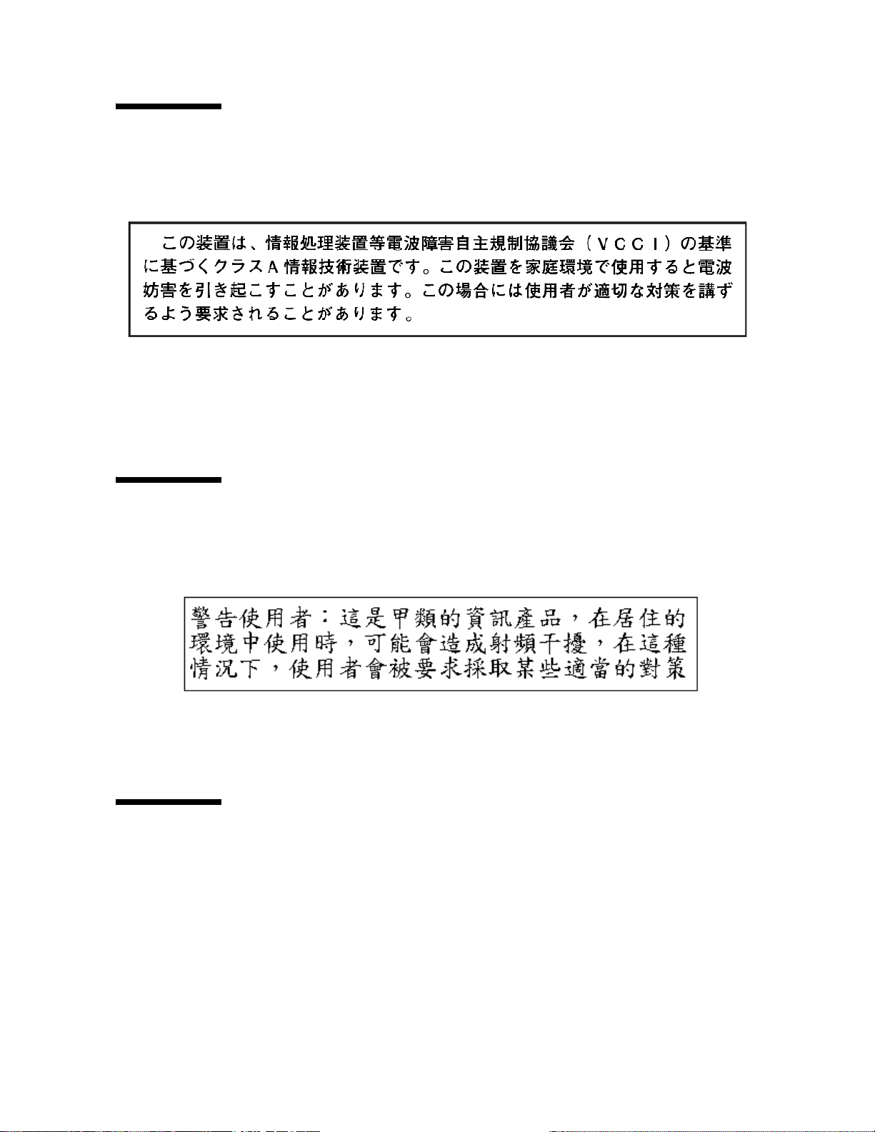
Japanese Compliance Statement
The following compliance statement in Japanese pertains to VCCI EMI regulations:
English translation: This is a Class A product based on the Technical Requirement of
the Voluntary Control Council for Interference by Information Technology (VCCI). In a
domestic environment, this product may cause radio interference, in which case the
user may be required to take corrective actions.
Taiwan Warning Label Statement
The following warning label statement pertains to BSMI regulations in Taiwan, R.O.C.:
English translation: This is a Class A product. In a domestic environment, this product
may cause radio interference, in which case, the user may be required to take adequate
measures.
Internal Code License Statement
The following is the Internal Code License Agreement from StorageTek:
xxviii StreamLine™ SL8500 Modular Library System User's Guide • March 2007 Revision K • 96154
Page 31

NOTICE
INTERNAL CODE LICENSE
PLEASE READ THIS NOTICE CAREFULLY BEFORE INSTALLING AND OPERATING THIS EQUIPMENT.
THIS NOTICE IS A LEGAL AGREEMENT BETWEEN YOU (EITHER AN INDIVIDUAL OR ENTITY), THE
END USER, AND STORAGE TECHNOLOGY CORPORATION (“STORAGETEK”), THE MANUFACTURER
OF THE EQUIPMENT. BY OPENING THE PACKAGE AND ACCEPTING AND USING ANY UNIT OF
EQUIPMENT DESCRIBED IN THIS DOCUMENT, YOU AGREE TO BECOME BOUND BY THE TERMS OF
THIS AGREEMENT. IF YOU DO NOT AGREE WITH THE TERMS OF THIS AGREEMENT, DO NOT OPEN
THE PACKAGE AND USE THE EQUIPMENT. IF YOU DO NOT HAVE THE AUTHORITY TO BIND YOUR
COMPANY, DO NOT OPEN THE PACKAGE AND USE THE EQUIPMENT. IF YOU HAVE ANY
QUESTIONS, CONTACT THE AUTHORIZED STORAGETEK DISTRIBUTOR OR RESELLER FROM WHOM
YOU ACQUIRED THIS EQUIPMENT. IF THE EQUIPMENT WAS OBTAINED BY YOU DIRECTLY FROM
STORAGETEK, CONTACT YOUR STORAGETEK REPRESENTATIVE.
96154 • Revision K Notices xxix
Page 32

1. Definitions: The following terms are defined as
followed:
a. “Derivative works” are defined as works based
upon one or more preexisting works, such as a
translation or a musical arrangement, or any
other form in which a work may be recast,
transformed, or adapted. A work consisting of
editorial revision, annotations, elaboration, or
other modifications which, as a whole, represent
an original work of authorship, is a Derivative
work.
b. “Internal Code” is Microcode that (i) is an
integral part of Equipment, (ii) is required by
such Equipment to perform its data storage and
retrieval functions, and (iii) executes below the
user interface of such Equipment. Internal code
does not include other Microcode or software,
including data files, which may reside or execute
in or be used by or in connection with such
Equipment, including, without limitation,
Maintenance Code.
c. “Maintenance Code” is defined as Microcode and
other software, including data files, which may
reside or execute in or be used by or in
connection with Equipment, and which detects,
records, displays, and/or analyzes malfunctions
in the Equipment.
d. “Microcode” is defined as a set of instructions
(software) that is either imbedded into or is to be
loaded into the Equipment and executes below
the external user interface of such Equipment.
Microcode includes both Internal Code and
Maintenance Code, and may be in magnetic or
other storage media, integrated circuitry, or other
media.
2. The Equipment you have acquired by purchase or
lease is manufactured by or for StorageTek and
contains Microcode. By accepting and operating this
Equipment, you acknowledge that StorageTek or its
licensor(s) retain(s) ownership of all Microcode, as
well as all copies thereof, that may execute in or be
used in the operation or servicing of the Equipment
and that such Microcode is copyrighted by
StorageTek or its licensor(s).
3. StorageTek hereby grants you, the end user of the
Equipment, a personal, nontransferable (except as
permitted in the transfer terms below),
nonexclusive license to use each copy of the Internal
Code (or any replacement provided by StorageTek
or your authorized StorageTek distributor or
reseller) which license authorizes you, the end user,
to execute the Internal Code solely to enable the
specific unit of Equipment for which the copy of
Internal Code is provided to perform its data
storage and retrieval functions in accordance with
StorageTek’s (or its licensor’s) official published
specifications.
4. Your license is limited to the use of the Internal
Code as set forth above. You may not use the
Internal Code for any other purpose. You may not,
for example, do any of the following:
(i) access, copy, display, print, adapt, alter, modify,
patch, prepare Derivative works of, transfer, or
distribute (electronically or otherwise) or otherwise
use the Internal Code;
(ii) reverse assemble, decode, translate, decompile,
or otherwise reverse engineer the Internal Code
(except as decompilation may be expressly
permitted under applicable European law solely for
the purpose of gaining information that will allow
interoperability when such information is not
otherwise readily available); or
(iii) sublicense, assign, or lease the Internal Code or
permit another person to use such Internal Code, or
any copy of it.
If you need a backup or archival copy of the
Internal Code, StorageTek, or your authorized
StorageTek distributor or reseller, will make one
available to you, it being acknowledged and agreed
that you have no right to make such a copy.
xxx StreamLine™ SL8500 Modular Library System User's Guide • March 2007 Revision K • 96154
Page 33

5. Nothing in the license set forth above or in this
entire Notice shall convey, in any manner, to you
any license to or title to or other right to use any
Maintenance code, or any copy of such Maintenance
Code. Maintenance Code and StorageTek’s service
tools and manuals may be kept at your premises, or
they may be supplied with a unit of Equipment sent
to you and/or included on the same media as
Internal Code, but they are to be used only by
StorageTek’s customer service personnel or those of
an entity licensed by StorageTek, all rights in and to
such Maintenance Code, service tools and manuals
being reserved by StorageTek or its licensors. You
agree that you shall not use or attempt to use the
Maintenance Code or permit any other third party
to use and access such Maintenance Code.
6. You, the end user, agree to take all appropriate steps
to ensure that all of your obligations set forth in this
Notice are extended to any third party having
access to the Equipment.
7. You may transfer possession of the Internal Code to
another party only with the transfer of the
Equipment on which its use is authorized, and your
license to use the Internal Code is discontinued
when you are no longer an owner or a rightful
possessor of the Equipment. You must give such
transferee all copies of the Internal Code for the
transferred Equipment that are in your possession,
along with a copy of all provisions of this Notice.
Any such transfer by you is automatically (without
further action on the part of either party) expressly
subject to all the terms and conditions of this Notice
passing in full to the party to whom such
Equipment is transferred, and such transferee
accepts the provisions of this license by initial use of
the Internal Code. You cannot pass to the transferee
of the Equipment any greater rights than granted
under this Notice, and shall hold StorageTek
harmless from any claim to the contrary by your
transferee or its successors or assigns. In addition,
the terms and conditions of this Notice apply to any
copies of Internal Code now in your possession or
use or which you hereafter acquire from either
StorageTek or another party.
8. You acknowledge that copies of both Internal Code
and Maintenance Code may be installed on the
Equipment before shipment or included with the
Equipment and other material shipped to you, all
for the convenience of StorageTek’s service
personnel or service providers licensed by
StorageTek, and that during the warranty period, if
any, associated with the Equipment, and during
periods in which the Equipment is covered under a
maintenance contract with StorageTek or service
providers licensed by StorageTek, both Internal
Code and Maintenance Code may reside and be
executed in or used in connection with such
Equipment, and you agree that no rights to
Maintenance Code are conferred upon you by such
facts.
StorageTek or the licensed service provider may
keep Maintenance Code and service tools and
manuals on your premises but they are to be used
only by StorageTek’s customer service personnel or
those of service providers licensed by StorageTek.
You further agree that upon (i) any termination of
such warranty period or maintenance contract
period; or (ii) transfer of possession of the
Equipment to another party, StorageTek and its
authorized service providers shall have the right
with respect to the affected Equipment to remove all
service tools and manuals and to remove or disable
all Maintenance Code and/or replace Microcode
which includes both Internal Code and
Maintenance Code with Microcode that consists
only of Internal Code.
96154 • Revision K Notices xxxi
Page 34

xxxii StreamLine™ SL8500 Modular Library System User's Guide • March 2007 Revision K • 96154
Page 35

Safety
The following pages describe common practices concerning electrostatic discharge,
fiber optics, and library safety.
Electrostatic Discharge Damage Prevention
Before you touch any internal components in the library, including drives, you must
take precautions against electrostatic discharge (ESD).
Caution – Components are sensitive to static electricity: Even a small electrostatic
discharge can damage an electrical component that is inside the library. A damaged
component might not fail immediately, but over time, it will become worse and might
eventually cause an “intermittent” problem. Be sure that you touch an unpainted metal
surface of the library before you reach inside the library or touch the drives or optional
interface equipment.
Before you touch any internal components:
1. With your finger, touch an unpainted metal surface of the library. In some libraries,
you can touch the library’s frame. In other libraries, you might have to touch a bolt
on the wall or on the door frame.
2. Keep your body movement to a minimum as you touch the drives or the library
components.
Antistatic wrist straps that have clip-on ends are commercially available.
96154 • Revision K xxxiii
Page 36

Fiber-optic Safety
Warning – Possible Physical Injury. '[ G J C \C T F . Never look directly into a
fiber-optic cable, a fiber-optic connector, or a laser transceiver module.
Hazardous conditions might exist from laser power levels that are capable of
causing injury to the eye.
Be especially careful when using optical instruments with this equipment. Such
instruments might increase the likelihood of eye injury.
The laser transceivers in fiber-optic equipment can pose dangers to personal safety.
Ensure that anyone who works with this StorageTek equipment understands these
dangers and follows safety procedures. Ensure that the optical ports of every laser
transceiver module are terminated with an optical connector, a dust plug, or a cover.
Each fiber-optic interface in this StorageTek Fibre Channel equipment contains a laser
transceiver that is a Class 1 Laser Product. Each laser transceiver has an output of less
than 70 µW. StorageTek’s Class 1 Laser Products comply with EN60825-1:1994+A1+A2
and with sections 21 CFR 1040.10 and 1040.11 of the Food and Drug Administration
(FDA) regulations.
Caution – Use of controls or adjustment or performance of procedures other than
those specified herein might result in hazardous radiation exposure.
The following translations are for users in Finland and Sweden who wish to identify
laser safety and classification:
CLASS 1 LASER
LUOKAN 1 LASERLAITE
KLASSE 1 LASER APPARAT
Laser Product Label
In accordance with safety regulations, a label on each StorageTek Fibre Channel product
identifies the laser class of the product and the place and date of the manufacturer. The
label appears on top of a Fibre Channel tape drive and near the Fibre Channel
connectors on a Fibre Channel tape library. A copy of the label is shown here:
CLASS 1 LASER PRODUCT
LASER KLASSE 1
APPAREIL A LASER DE CLASSE 1
COMPLIES WITH 21 CFR 1040.10 AND 1040.11
xxxiv StreamLine™ SL8500 Modular Library System User's Guide • March 2007 Revision K • 96154
Page 37

EN60950-1:2001 Statement
The following statement pertains to products that require a ground connection at the
wall outlet.
Norway:
Apparatet må tilkoples jordet stikkontakt
Finland:
Laite on liitettävä suojamaadoituskoskettimilla varustettuun
pistorasiaan
Sweden:
Apparaten skall anslutas till jordat uttag
Denmark:
For tilsluting af de øvrige ledere, se medfølgende
installationsvejledning
Library Safety
It is essential that safety procedures are followed. Be sure you are familiar with all the
precautions in this section before you attempt to enter the library. Interlocks, robotics
emergency robotics stop switches, and smoke detectors are provided to assure safety
throughout the library.
Mechanical Access Door Mechanisms
On the rear of each door lock, a mechanism (painted yellow) is available to release the
door lock from the inside of the library. This is a non-electrical safeguard against being
locked inside the library.
Should an access door be shut and locked from the outside, someone inside the library
need only push on the mechanism to unlock and open the door.
SL8500 Door Interlocks
The library features two types of safety interlocks:
■ Door frames: Two redundant switches behind each front access door of the Customer
Interface Module.
■ Service safety door: Two sets of dual switches located on the upper section of the
front frame for the service safety door.
96154 • Revision K Safety xxxv
Page 38

When two libraries are connected by a pass-thru port (PTP), entering the interior of
either library automatically suspends the pass-thru operations in the two libraries.
Operations also stop within the library with the open door, while the other library’s
operation continues.
Door Switches
The library has four front door switches on the Customer Interface Module that
monitor the state of the front access doors; should a door be opened without using
service mode, these switches remove power from the robotics.
Emergency Robotics Stop Switches
Emergency robotic stop (ERS) is the removal of AC and DC power to the robotics, such
as the HandBots, pass-thru ports, CAPs, and elevators; the library and tape drives are
not affected. The emergency robotic stop ensures that no robotic motion occurs while
someone is inside the library.
In case of a condition that requires an immediate power-off of the library, there are two
ERS switches for the library:
■ One interior, lighted switch on the left side of the drive area, as seen from the front
of the machine
■ One non-illuminated, covered switch on the front operator key panel
Pressing an ERS switch immediately removes AC and DC power to the robotics (not the
entire library). After it is determined that it is safe to restore power, press the switch
again to reset it.
Smoke Detection
A smoke detector is present within the library. The smoke detector is in the upper right
section of the drive and electronics module, as seen from the rear of the machine.
If the detector senses smoke, the library performs an emergency power-off (EPO)
procedure, removing all (AC and DC) power from the library. Call your service
representative to diagnose the problem.
The replacement of the smoke detector is an annual preventative maintenance
requirement.
Fire Suppression
The library does not ship with a Fire Suppression System installed, although features
have been incorporated into the library to allow fire suppression systems to be
installed. Professional Services can install a Fire Suppression System on site. Contact
your service representative for more information.
xxxvi StreamLine™ SL8500 Modular Library System User's Guide • March 2007 Revision K • 96154
Page 39

Service Safety Door
The optional service safety door is a sliding door that is activated by the maintenance
key. This maintenance key is controlled only by service representatives and is used
when a failing component in the front of the library needs to be replaced.
The service safety door moves either to the left or right, depending upon which
maintenance lock is opened. When the maintenance key is inserted into its lock and
turned, the safety door separates the forward maintenance area from the library
interior. This allows the service representative to safely replace a failing front frame
component while the library remains fully operational.
The Service Safety Door is an optional feature for libraries with four HandBots.
However, it is required for redundant (eight) HandBot operation.
The service safety door moves either to the left or right, depending upon which
maintenance lock is opened. When the maintenance key is inserted into its lock and
turned, the safety door separates the forward maintenance area from the library
interior. This allows the service representative to safely replace a failing front frame
component while the library remains fully operational.
Interior Lighting
The interior of the library is always illuminated with white LEDs on the ceiling. The
ceiling of the Customer Interface Module has yellow (hazard) LEDs that flash when the
library is in service mode and for approximately 10 seconds when the doors are closed
to alert anyone who may still be inside the library.
SL8500 Servo Power Interrupt
An additional safety feature is the servo power interrupt (SPI). If a library motor is
determined to be out-of-range, the processor generates an SPI to turn off drive voltage
to the faulty motor. This prevents a servo runaway condition until the cause of the
problem can be determined.
96154 • Revision K Safety xxxvii
Page 40

xxxviii StreamLine™ SL8500 Modular Library System User's Guide • March 2007 Revision K • 96154
Page 41

CHAPTER
1
Introduction
This chapter introduces the major hardware components and provides the library
specifications for the StreamLine
to as the SL8500 library or just the “library” throughout this manual. For software
information and drive information, refer to the publications that pertain to these
specific topics.
The library is a robotic system that mounts cartridges into storage slots or into drives
for read/write operations. It also moves cartridges between the cartridge access port
(CAP) to storage slots or between slots.
TM
SL8500 modular library system, which is referred
Library Overview
The SL8500 Library is a fully automated cartridge tape storage and retrieval system.
The base library stands 2.37 m (7.76 ft.) tall, 1.7 m (5.6 ft.) wide, and 2.76 m (9.1 ft.)
deep. Depending on the model and features selected, one SL8500 library can store from
1,448 to 6,632 cartridge tapes and house from four to 64 tape drives.
A library complex, consists of two or more libraries that connect with pass-thru ports
(PTPs) and contains over 320,000 customer usable cartridges and 2,048 tape drives.
The approximate speed of each robot (termed StreamLine HandBot™ high performance
robotics) is from 2 m (75 in.) to 2.5 m (100 in.) per second.
96154 • Revision K 1
Page 42

Library Overview
Single Physical SL8500 Library—Base
The minimum SL8500 library configuration is composed of:
■ A Drive and Electronics Module, containing from four to 64 tape drives and the
controlling circuit cards for the library
■ One Robotics Interface Module, containing up to 800 cartridge storage slots
■ Multiple HandBots (four – eight) that service four rails. They move horizontally
along rails and vertically along their individual Z axes. They retrieve cartridges from
both inner and outer walls (and the elevator and turntable assembly or CAPs) by
pivoting 180 degrees
■ One Customer Interface Module that contains 648 data cartridges slots, 198 diagnostic
and cleaning cartridges slots, 24 end slots (eight 3-slot arrays) for targeting and drop-off
cells,
and an LED display
■ A remote “operator panel” (StreamLine Library Console
operator panel display on the customer’s personal computer [PC])
■ An elevator assembly located in the front (Customer Interface Module), that
transfers cartridges vertically across rail boundaries (elevator) or from one side of
the library to the other (by passing them to either HandBot using a turntable)
■ A standard cartridge access port (CAP) that allows up to 39 cartridges to be
entered/ejected at one time
TM
software that provides an
Single Physical SL8500 Library—Options
Options for each stand-alone SL8500 library are:
■ A maximum of five additional storage expansion modules, providing 1,728 cartridge
storage slots each, to a maximum cartridge storage number of 10, 088 cartridges
within one library
■ A touch-panel operator control in the middle of the Customer Interface Module,
between the two access doors
■ An optional second CAP (CAP B) is also available
■ Redundant HandBots (maximum of four) that provide redundancy should one robot
encounter a failure
■ One service safety door for maintenance activity
■ Library partitioning—a licensed feature that allows SL8500 rails (LSMs) to be
partitioned for exclusive use by separate hosts. See “Library Partitioning” on page 22
for details.
A view of a library with one expansion frame is shown in FIGURE 1-1 on page 3.
2 StreamLine™ SL8500 Modular Library System User's Guide • March 2007 Revision K • 96154
Page 43

FIGURE 1-1 Library Modules
6
Library Modules
1
5
1. Drive and electronics module
2. Robotics interface module
3. Storage expansion module
Library Modules
The base library consists of three modules:
1. Drive and Electronics Module
2. Robotics Interface Module
3. Customer Interface Module
2
3
4
4. CAPs A and B (shown on front, right door)
5. Left front door
6. Customer Interface Module
Besides the three modules, up to three Storage Expansion Modules may be added per
library to increase capacity. These expansion modules are installed between the
Robotics Interface Module and the Customer Interface Module.
96154 • Revision K Chapter 1 Introduction 3
Page 44

Library Modules
X
XEX
X
With a PTP installed between two or more libraries, all libraries can share their
cartridges and effectively act as a single system.
FIGURE 1-2 Base Library with One Storage Expansion Module
6
11
10
9
8
7
1. Cartridge Access Ports (2) Caps
2. Facade Operator Panel (Optional) Icey Pad
3. Customer Interface Module
4. Storage Expansion Module
5. Robotics Interface Module
6. PTP (Pass Through Port)
7. Drive Electronics Module
5
6
8. AC Power Supplies Electronic Control Module
9. DC Power Supplies
10. Tape Drives
11. Accessory Racks
12. Inner Wall
13. Service Door
14. Reserved Columns
E= End Stop
X= Diagnostic & Cleaning Cartridge
12 13
4
14
1
2
E
3
L203_054
Capacities
The following table shows the data cartridge capacities in a single library:.
TABLE 1-1 Data Cartridge Capacity
Module Type Cartridge Capacity
Drive and Electronics
Robotic Interface 800
Customer Interface
Basic Library
Basic library 1,448
4 StreamLine™ SL8500 Modular Library System User's Guide • March 2007 Revision K • 96154
1
2
0
648
Page 45

Drive and Electronics Module
TABLE 1-1
Expansion Modules
Data Cartridge Capacity (Continued)
Module Type Cartridge Capacity
First storage expansion module 3,176
Second storage expansion module 4,904
Third storage expansion module 6,632
Fourth storage expansion module 8,360
Fifth storage expansion module 10,088
1
There are no cartridge storage locations in the Drive and Electronics Module.
2
The Customer Interface Module contains 198 storage slots for cleaning and diagnostic cartridges
Note – This total number of cartridges does not include slots in the cartridge access
port (CAP), pass-thru-port.
See Appendix A, “Cartridge Slot Locations” for information on reserved slots and
cartridge addresses.
Drive and Electronics Module
.
The major components of this module include:
■ AC power distribution units N+1 (standard) or 2N (optional) (see “Power” on
page 17)
■ Load sharing DC power supplies that provide power for the tape drives and
HandBots
■ Electronics control modules (ECM) and cards for library operation (see “Electronics
Control Module” on page 7)
■ Accessory racks to mount network devices and components, servers, and the service
delivery platform
■ Slots for 1 to 64 tape drives
Tape Drives
SL8500 library supports from 1 to 64 drives. The interface to these drives is fiber-optic
based; meaning Fibre Channel, FICON
1. Short for Fiber Connection, or Fiber Connectivity—IBM’s fiber optic channel technology that extends the
capabilities ESCON. FICON supports full duplex data transfers over longer distances.
2. Short for Enterprise Systems Connection, or Enterprise Systems Connectivity—an IBM fiber optic channel technology
that supports half duplex data transfers up to 200 Mb/s.
1
, or ESCON2 attachments.
96154 • Revision K Chapter 1 Introduction 5
Page 46

Drive and Electronics Module
The following table lists the supported vendors, drives types, and interfaces.
TABLE 1-2 Supported Drives
Vendor Drive Type Host Interface Type
T9840A Fibre Channel, ESCON
StorageTek
HP Linear Tape-Open (LTO 2, 3) Fibre Channel
IBM Linear Tape-Open (LTO 2, 3) Fibre Channel
Quantum Linear Tape-Open (LTO 3) Fibre Channel
Quantum Super DLT (SDLT600) Fibre Channel
T9840B Fibre Channel, FICON, ESCON
T9840C Fibre Channel, FICON, ESCON
T9940B Fibre Channel, VSM ESCON
T10000 Fibre Channel
StorageTek T-Series Tape Drives
The StorageTek T-Series tape drives are small, modular, high-performance drives
designed for both the enterprise and client-server environments.
T9x40
StorageTek’s T9x40 tape drives are high-performance drives designed for enterprise
and client-server environments. There are two models available:
T9840 The access-centric T9840 tape drive is ideal for applications that demand high data
throughput and fast recall. These drives give you access to data at an average of 8
seconds, store up to 40 GB, with transfer rates of up to 30 MB/s.
The SL8500 supports all three models of the T9840 (A, B, and C).
T9940 The T9940 tape drives are designed for high-capacity storage applications. They use
a single reel cartridge tape for higher capacities of up to 200 GB with transfer rates
of up to 30 MB/s.
The T9940A tape drive is not supported.
Note:
T10000
StorageTek’s T10000 are high-capacity, high-performance tape drives. These drives use
a single reel data cartridge with a native storage capacity of up to 500 GB (native) and
transfer rates of up to 120 MB/s. These new tape drives are designed to take advantage
of the new speeds in storage area networks (SANs)—4 Gb/s.
6 StreamLine™ SL8500 Modular Library System User's Guide • March 2007 Revision K • 96154
Page 47

LTO Ultrium
Ultrium Linear Tape-Open (LTO) technology was developed jointly by HewlettPackard (HP), IBM, and Seagate to enable data interchange among different LTO
Ultrium tape drive vendors. LTO is an “open format” technology, which means that
users have multiple sources of product and media. The “open” nature of LTO
technology enables compatibility between the three different vendors.
The SL8500 supports the Ultrium Generation 2 and 3 LTO drives available
from HP, IBM, and Quantum. These drives use a single reel data cartridge with native
transfer rates and capacities of up to
■ 35MB/s with capacities of 200 GB for LTO2 drives
■ 80 MB/s with capacities of 300 GB for LTO3 drives
TABLE 1-3 LTO Drive Backward Readability
LTO Gen 2 Drive LTO Gen 3 Drive
LTO 1 media Read and write Read only
LTO 2 media Read and write Read and write
LTO 3 media No action Read and write
Drive and Electronics Module
Super DLT
The Super DLT (SDLT) is a standard for mid-range UNIX and Windows platforms. The
SDLT 600 incorporates an advanced tape recording technology for high capacity tapes,
up to 300 GB, with transfer rates of 36 MB/s.
Electronics Control Module
Each library contains an electronics control module.
HBK Card
The HBK card contains flash memory and feature upgrade controls; it resides on a
separate logic card within the control module. It contains the configuration, firmware
versions, and features for the library.
Configuration
Library configuration is retained on the flash memory card. This saves significant time
in cases where an HBC card must be replaced, because the new card fetches the
configuration from flash memory instead of requiring manual re-configuration by a
service representative.
96154 • Revision K Chapter 1 Introduction 7
Page 48

Robotics Interface Module
Firmware Versions
Flash memory holds both the most recently activated firmware version and the
previous firmware version. Therefore, if there is a requirement to return machine
control to a previous version, a service representative merely re-activates the previous
version and places the now-deactivated version into the “previous” state.
Features
When features are added to a library, they are tracked to the machine’s serial number3.
Any upgrade must be matched to the serial number before activation. The upgrade
process is accomplished over the command line interface (CLI) by the service
representative.
HBC Card
The HBC card is the library controller, responsible for coordinating all component
operations within the library. It is the interface between the host and the library. One
HBC card can control a library’s operation, but a second HBC is available to assure
redundancy. Operating voltage for HBC cards is +3.3 VDC.
In addition to the cards in the electronics control module, the HBC card interfaces with
the following cards and components:
■ Ethernet hubs (Library-to-library LANs, tape drive service LAN)
■ TCP/IP/Web host interface
■ HBS cards (robots)
■ Power, smoke, and environmental monitoring circuits throughout the library
■ Flash memory
HBT Card
The HBT card translates commands from the HBC controller card into unique drive
commands, transferred across differential RS422 lines. The HBT card contain 66
Universal Asynchronous Receiver/Transmitters (UARTs); 64 are responsible for the
parallel-to-serial conversion for the tape drives and the remaining two communicate
with the tape environmental monitor card (HBD card).
Robotics Interface Module
The robots move cartridges between storage slots, between slots and tape drives, and
between the CAP and slots.
There are four robotic rail assemblies in the library that provide both power and
communications to the four or eight robots. Each robot can service up to 16 tape drives.
Robots consists of:
■ Rail, brush, and HandBot assemblies
3. The machine serial number is on the rear, bottom of the Tape Drive and Electronic Module.
8 StreamLine™ SL8500 Modular Library System User's Guide • March 2007 Revision K • 96154
Page 49

Robotics Interface Module
■ A Z-mechanism for vertical motion of the hand
■ A wrist-mechanism for lateral or horizontal motion
■ A bar-code scanner for both targeting and reading cartridge labels
■ A proximity sensor for detection of empty slots and unlabeled cartridges
■ A belt-driven gripper mechanism for gripping the sides of the cartridges
Important:
Because of the four individual rails, each robotic assembly is considered a library
storage module (LSM). So the architecture of the SL8500 provides four separate and
unique LSMs within a single library.
To optimize system performance, the HandBots automatically implement the Fast Load
capability. Once a HandBot successfully inserts a cartridge into a drive, it is
immediately available for the next request and does not wait until the drive reports that
the cartridge has been loaded. The SL8500 library control electronics waits to return the
response to the mount request until it detects that the tape drive has successfully
loaded the cartridge tape.
Two HandBots can service a single rail section within the library, providing
redundancy. Each HandBot has two motors, if one fails, the other motor is powerful
enough to move the defective HandBot into the forward service area. If both the motors
fail for a HandBot, then the redundant HandBot moves the defective HandBot into the
forward service area thus continuing HandBot operations.
One robotics interface module contains up to 800 cartridge storage slots.
FIGURE 1-3 HandBot (Detail)
3
2
1
1. Lower pulley
2. Pre-load assembly
3. Gripper
4. HBB card
4
L203_578
96154 • Revision K Chapter 1 Introduction 9
Page 50

Robotics Interface Module
FIGURE 1-4 HandBot on the Power Rail)
Redundant HandBots
Make sure that the service representative completes the following are prerequisite to
the operation of the redundant HandBots (two HandBots per rail):
1. Install the Service Safety Door
2. Upgrade the HandBot assemblies
3. Upgrade the library firmware (FRS 2.50 or later)
4. Upgrade the HBS assemblies; these have an “X” on the upper left of the assembly
5. Upgrade the HBN card
6. HBQ rail terminator cards
7. ENDSTOP bar code inserts in the 3-cell arrays at the ends of all rails
8. Additional DC power supplies
Initialization
When power is applied to the library, each HandBot begins its initialization routine.
The sequence for initialization is in the following order:
10 StreamLine™ SL8500 Modular Library System User's Guide • March 2007 Revision K • 96154
Page 51

Robotics Interface Module
Note – If there are multiple HandBots, each HandBot attempts initialization through
the following sequence. If a failure is encountered in one HandBot, that HandBot is
flagged as defective. Initialization continues for the other HandBots and, after they are
successfully initialized, the defective HandBot is pushed into the maintenance area for
replacement.
1. Logic/controller cards initialize (HBC, HBB).
2. Rail communication is established with the HandBots: this is accomplished through
the HandBot’s electrically conductive brushes that contact the rail. HandBots are
identified by number and hand address:
a. Number: the HandBot that encounters the left stop (referenced from the front of
the customer interface module) is HandBot number “1,” the one encountering the
right stop is HandBot number “2.”
b. Hand address: according to their rail location (numbered 1—4, from the top,
down). See “HandBot Numbering” on page 12 for more information.
3. If a service safety door is installed, the HBC card checks that:
a. Both maintenance keys are in the vertical (OFF) positions
b. The door is in the center (disengaged) position. If the door is not in the correct
position, the HBC card will issue the command to move it into its center position.
4. HandBots move vertically (this is the only HandBot motion that is controlled by the
microcode within the HandBot’s HBB card—all other motions are controlled by the
HBC card)
5. The gripper sensors are checked.
6. The hand retracts – this protects:
a. Hand components—if the hand’s “reach safe” sensor cannot be detected,
initialization stops.
b. A customer cartridge that may have been left in the gripper during a power
failure. If this is the case, the “cartridge present” sensor activates and the hand
holds the cartridge in the retracted position.
7. Belt-driven wrist moves counterclockwise.
8. For libraries without redundant HandBots, each HandBot moves to both the left and
right end stops.
9. For redundant HandBots:
a. Both HandBots move to their respective end stops
b. Both HandBots initialize.
c. The right HandBot remains at its end stop.
d. The left HandBot moves around the track to meet the right HandBot. This
distance is calculated by the HBC card as the absolute track distance
e. The left HandBot moves to the end of its track
96154 • Revision K Chapter 1 Introduction 11
Page 52

Robotics Interface Module
10. HandBots move to an empty slot detection area (the slot under the bar code insert,
in the 3-cell array at the front of the customer interface module) to verify proximity
sensor accuracy. During normal operation, if an empty slot is detected, the “empty
slot detector” sensor is activated; non-labeled cartridges are also detected.
11. Belt-driven reach mechanism initializes by a wrist motion, pointing the hand to an
aisle position, and reach components are then verified.
12. Gripper, reach, and scanner initialization is accomplished at the three cell array
section:
a. If there is no cartridge in the gripper, the initialization continues.
b. If a cartridge is in the hand, the hand moves to the drop-off slot, the cartridge is
Note – Cartridge drop-off slots are the bottom slots in the 3-cell arrays and the top
fixed array slots under the PTP locations leading to a total of 16.
13. Hand points toward the rear of the library.
14. End status sent to HBC card.
placed in the slot, and gripper initialization continues.
Note – If any hand or robotic error cannot be resolved by error recovery routines, the
entire HandBot must be replaced.
HandBot Numbering
Rails are numbered from 1 (top rail) to 4 (bottom rail). They are also designated as
separate library storage modules (LSMs) within a library.
As examples:
■ Rails 1 and 2 can be designated LSMs for HSC, while rails number 3 and 4 can be
designated LSMs for ACSLS.
■ If only one host exists, all rails become separate LSMs for that host.
See Appendix A, “Cartridge Slot Locations” for more details.
HandBots have the following numbering:
1. Library number (within a library complex)
2. Rail number – Rails are numbered 1 through 4, rail 1 is the top rail
3. Column number – Columns are “signed” numbers referenced from the customer
interface module, where +1 is right of the center of the drive bays and -1 is to the left
of the drive bays
4. Side number – Outer wall = 1, Inner wall = 2
12 StreamLine™ SL8500 Modular Library System User's Guide • March 2007 Revision K • 96154
Page 53

Robotics Interface Module
Note – Side numbers for HandBots are numbered according to their end stops: 1 (left
HandBot stop) and 2 (right HandBot stop).
5. Row number – Numbered consecutively, from the top down
Note – Because HandBot hands are not storage slots, their row numbering is 0.
As examples:
■ Location 1, 1, 0, 1, 0 = the HandBot on rail 1 (top rail) that encounters the stop on the
left side of the customer interface module
■ Location 1, 1, 0, 2, 0 = the HandBot on rail 1 (top rail) that encounters the stop on the
right side of the customer interface module
■ Location 1, 2, 0, 1, 0 = the HandBot on rail 2 (next rail down) that encounters the stop
on the left side of the customer interface module
FIGURE 1-5 on page 13 shows how this notation appears on the StreamLine Library
Console.
FIGURE 1-5 StreamLine Library Console – HandBot Display
96154 • Revision K Chapter 1 Introduction 13
Page 54

Library Cameras
Library Cameras
An Ethernet-based library camera system (WebCam) with monitoring software are
optional features of the SL8500 library. The cameras allows you to remotely see the
inside of their SL8500 library. The WebCam attaches to a 10Base-T, 100Base-T Ethernet
connection and provides remote, high-quality, audio and video. This feature contains
two cameras that mount in the upper frame of the front access door-one on each side of
the library.
Note – The WebCam feature uses a third party camera designed for the security
surveillance market and is subject to change without notice.
Customer Interface Module
The customer interface module consists of the following components:
Keypad
FIGURE 1-6 Keypad
1
1. Emergency robotics stop switch
2. Left service safety door key
3. CAP A button
4. Library active indicator
2 4 5
8
CAP A
3
5. CAP B button
6. Service required indicator
7. Right service safety door key
8. CAP unlocked indicators
CAP B
6
7
L203_470
14 StreamLine™ SL8500 Modular Library System User's Guide • March 2007 Revision K • 96154
Page 55

The keypad has the following buttons, switches, and indicators:
TABLE 1-4 Keypad Switches, Buttons, and Indicators
Customer Interface Module
Emergency robotics stop
switch
CAP A button Press to open and close CAP A.
CAP B button Press to open and close CAP B.
CAP unlocked indicators The amber LED light is On when the CAP is unlocked, and Off when locked.
Service required indicator This red indicator is lit when operator intervention is required.
Service safety door keys (left
and right doors)
Actuate the emergency robotics stop switch to disconnect DC power to the
power rails. When it is safe to restore power, press the switch to restore power
to the rails.
When the light is On and blinking, manual intervention required. Open the
CAP and make sure the cartridges in the CAP slots are properly seated.
Allows the service representatives to place the library in maintenance mode.
Operator Panel
In the SL8500, the StreamLineTM Library ConsoleTM software is the operator panel
software application capable of execution on both a local operator console (touch-screen
panel resident within the SL8500 frame), as well as a remote operator console (network
PC).
The Library Console runs a JAVA application that provides the graphical user interface
(GUI) for the library. The Library Console communicates to the library controller (HBC)
through an Ethernet connection. In compliance with section 508 of the Americans with
Disabilities Act, the touch-panel is accessible from a sitting or standing position.
The keypad interface of the software for the touch-panel enables alphanumeric data
entry to the operator panel application from the local operator panel. The local operator
panel does not contain either a keyboard or a mouse.
Use the Library Console to:
■ View and modify status and properties of the library and the associated devices (drives,
CAP, robots, and elevators)
■ Perform library audit, self test, and code load
■ Locate cartridges
■ Display standard reports
■ Display standard events
Local Operator Console
The local operator console is an optional feature on the front of the library. This panel
consists of a flat screen display with a touch-screen interface. The local operator console
has the following features:
■ 12.1 inch flat panel display
■ Touch screen interface (no keyboard/mouse option)
■ A pen and stylus are available for the touch screen interface
■ Resident within the library frame
■ Ethernet interface
■ JAVA application that provides the Graphical User Interface (GUI) for the library
96154 • Revision K Chapter 1 Introduction 15
Page 56

Customer Interface Module
Remote Operator Console
The remote operator console is a standard feature that displays the operator panel
application on a personal computer (PC). A CD containing the Library Console
software is supplied with each library that you can use to install the application.
Capacities
A basic library can store up to 1,448 data cartridges. This total does not include
cartridges in the cartridge access port (CAP) or the reserved slots. A total of 198 slots
are dedicated to diagnostic and cleaning cartridges. See Appendix A, “Cartridge Slot
Locations” for information on slot locations.
There are also eight drop-off slots in the library, two for each robot. These slots are
used in the event of a robotic failure when there is still a cartridge in the hand.
TABLE 1-5 lists the capacity variations for the SL8500 library.
TABLE 1-5 SL8500 Capacity Variations
Module Type Cartridge Capacity
Drive and Electronics
Robotic Interface 800
Customer Interface
Basic library 1,448
First storage expansion module 3,176
Second storage expansion module 4,904
Third storage expansion module 6,632
Fourth storage expansion module 8,360
Fifth storage expansion module 10,088
1
There are no cartridge storage locations in the Drive and Electronics Module.
2
The Customer Interface Module contains 198 storage slots for cleaning and diagnostic cartridges
1
2
0
648
.
Elevator
Elevators provide vertical pass-thru operations between rails within the same library.
Both elevators are located in the front of the library between the front access doors and
the Service Safety Door. Each of the four rails share the two elevators.
Cartridge Access Port (CAP)
CAPs allow operators to enter cartridges and eject cartridges from the library. A total of
39 cartridges can be imported or ejected at one time through each CAP. SL8500 library
CAPs are installed on the right access door. FIGURE 1-7 on page 17 illustrates the
CAPs. See Chapter 4, “Library Operation” for information on CAP operation.
16 StreamLine™ SL8500 Modular Library System User's Guide • March 2007 Revision K • 96154
Page 57

FIGURE 1-7 CAP
g
e
Storage Expansion Modules
Note – A CAP will not operate unless the library is in the automated mode.
1
2
3
4
4 Rails
The CAP spans across three rails—2, 3, and 4 (LSMs 1, 2, and 3).
Storage Expansion Modules
Besides the basic configuration, up to five Storage Expansion Modules may be added
per library to increase capacity. These expansion modules are installed between the
Robotics Interface Module and the Customer Interface Module.
1
2
3
3 CAP
Ma
azin
Each Storage Expansion Module can contain up to 1,728 data cartridge slots.
Power
There are five (5) power grids that distribute power throughout the library. Two of the
power grids carry 220 VAC; the other three carry 48 VDC.
96154 • Revision K Chapter 1 Introduction 17
Page 58

Power
■ The two AC power grids distribute 220 VAC to the different Load Sharing Power
Supplies, Electronics Control Module (ECM), and accessory racks.
■ The three DC power grids supply 48 VDC to the tape drives, robots, and front frame
components.
■ The Drive Power Grid supports up to 64 tape drives (with the proper number of
Load Sharing Power Supplies). A single tape drive power supply provides power
for up to 8 tape drives, so at least 8 power supplies are required for 64 tape drives
(in an N+1 configuration).
■ The Robot and Pass-thru Port (PTP) Power Grid supplies power to the robots and
the four pass-thru ports (PTP). A single power supply can power up to four
robots, so two power supplies are required for eight robots.
■ The Front Frame Power Grid is powered by a single Load Sharing Power Supply
that supplies 48 VDC power to the two Cartridge Access Ports if present, one
Turntable, two Elevators, and the Service Safety Door.
Note – The power supply for the Front Frame Power Grid is in the Customer Interface
Module. All the other Load Sharing Power Supplies are located in the Drive and
Electronics Module.
Power Consumption
Power consumption for the library is as follows:
■ Single phase configurations
■ 24 Amps per phase (minimum) – 13.0kW, 44,382 Btu/hr
■ 768 Amps per phase (maximum) – 416 kW, 1.4 M Btu/hr
■ Three phase configurations
■ 40 Amps per phase (minimum) – 13.0 kW, 44,382 Btu/hr
■ 280 Amps per phase (maximum) – 416 kW, 1.4 M Btu/hr
Note – Power cabling must be done by a licensed electrician.
Power Configurations
Two power configurations are available for the SL8500 library:
1. N+1 base power configuration
2. 2N power configuration
N+1 Base Power Configuration
The base power configuration contains one system power distribution unit (PDU) and
one N+1 PDU.
18 StreamLine™ SL8500 Modular Library System User's Guide • March 2007 Revision K • 96154
Page 59

Library Complex
■ The system PDU, connected directly to the branch circuit, provides AC power to
three DC power grids and the electronics control module.
■ The N+1 PDU supplies added +48 VDC load sharing power to each of the three DC
power grids and an extra AC-to-DC power supply for the electronics control
module.
The base power configuration provides power to the:
■ Tape drive power supplies
■ Robotic rail power supplies
■ Customer Interface Module power supplies
■ Touch screen operator control panel
■ Electronics control module power supplies
Note – The base power configuration does not offer redundant AC power.
2N Power Configuration
The 2N power configuration contains the base power configuration (PDU 1) and a
second PDU, PDU number 2.
This configuration provides power to the same components as N+1, plus power for:
■ Optional, redundant load sharing power supplies
■ Two additional accessory racks for customer components
■ Redundant controller cards
Note – The 2N PDU is required for the 2N drive power, 2N robotic power, and also for
the additional rack installed.
Library Complex
A library complex is created by connecting two or more SL8500 libraries together with
Pass-thru Ports (PTPs).
The maximum size library complex possible consists of either:
■ 32 libraries for Host Software Component (HSC) systems, connected through PTPs,
containing over 320,000 cartridge slots and 2,048 tape drives.
■ 31 libraries for Automated Cartridge System Library Software (ACSLS) connection,
connected through PTPs, containing over 320,000 cartridge slots and 1,984 tape
drives.
Note – A library complex with functional pass-thru ports (PTPs) cannot be partitioned.
All PTPs must be disabled before partitioning can be enabled. See “Library
Partitioning” on page 22 for details.
96154 • Revision K Chapter 1 Introduction 19
Page 60

Library Complex
Pass-thru Ports
A PTP is an electro-mechanical device that allows one Library Storage Module (LSM) to
pass a cartridge to another library storage module within the same complex.
For example: If an operating system issues a mount request, and all the tape drives are
busy in that LSM and library, the PTP can pass the cartridge to another library where
an idle tape drive can satisfy the mount request.
There are eight PTP locations in an SL8500 library, two locations per rail (or LSM).
These locations are on the curved portions of the Robotic Interface Module near the
tape drives. Therefore, they provide quick access to the drives.
The SL8500 PTPs consist of a separate frame (FIGURE 1-8) that is installed between the
Drive and Electronics Module and the Robotics Interface Module. Each frame has four
separate PTP mechanisms that can pass up to two cartridges each between LSMs (one
cartridge mechanism) for a total of eight cartridges.
The maximum size of a library complex connected through PTPs is 7 libraries.
FIGURE 1-8 Pass-thru Port
Note – Because elevators transfer cartridges from one LSM to another, these transfers
are also pass-through operations. The elevators are thus internal PTPs, considered by
host software to be on Panel 0.
The following terms and definitions apply to SL8500 PTP operations:
Home library Provides power, signal, and control lines to the PTP mechanisms. This is the
library on the right as viewed from the front.
Away library Always located on the left side of a Home library, as viewed from the front.
Source Contains the home slot location for the cartridge that will be passed through
to an adjacent library.
Destination Contains the tape drive or slot location in the adjacent library where the
cartridge will be mounted or stored.
20 StreamLine™ SL8500 Modular Library System User's Guide • March 2007 Revision K • 96154
Page 61

Embedded Firmware
All SL8500 libraries come equipped and ready for the addition of the PTP frame—no
additional walls are needed on existing libraries.
The software applications
Physical characteristics for the PTP assembly are listed in TABLE 1-6.
TABLE 1-6 PTP Assembly – Physical Characteristics
Height 231 cm (91 in.)
Width 17.2 cm (6.76 in.)
Depth 150.8 cm (59.4 in.)
Weight 121 kg (266 lb)
Power +48 VDC, supplied from the home side (left side of the library, as viewed from
the front) by the corresponding HBF card for each rail.
—ACSLS and HSCsupport PTP operations.
Embedded Firmware
Operating firmware is resident on the HBC card from the factory. The features of the
firmware are explained in the following sections.
Security
Access to the Library Console is secured by a fixed set of user accounts at the site. The
site user accounts include the customer administrator, StorageTek customer service
engineer (CSE), and third party field service technician.
The Library Console security system requires activation of the site user accounts with
an activation password (see “Activating Password” on page 28).
Operating Firmware
Some key features of the SL8500 firmware are:
1. Two firmware versions may be held on the HBC card. When firmware is upgraded,
the earlier image of firmware remains in memory and may be restored if required.
2. Auto Discovery of additional tape drives
3. Auto Discovery of new cartridge slots and added libraries
Automatic handling of dynamic World Wide Name (dWWN) assignments (See
“Dynamic World Wide Name” on page 29).
96154 • Revision K Chapter 1 Introduction 21
Page 62

Library Management Software
Library Management Software
The library management software controls the library hardware to mount and
dismount cartridges on drives and move the robot. When the library is in automated
mode, these operations occur without manual intervention. The software determines
the location of the cartridge by accessing the audit data uploaded from the library. The
software then allocates the drive to receive the cartridge.
These application maintain a database that tracks volume serial numbers (VOLID) of
cartridges and their current locations in the library.
Host Software Component
When an SL8500 library is in a configuration with a Multiple Virtual Storage (MVS)
host, the host must run a version of the StorageTek Host Software Component (HSC)
along with the Storage Management Component (SMC). HSC resides in the MVS host,
but is invisible to the actual operating system. HSC 6.0 or higher is required for host
control. However, for new drives, higher levels of HSC may be required.
ACSLS
ACSLS is a software package that manages library contents and controls library
hardware for the mounting and dismounting of cartridges. ACSLS 7.1 or higher is
required. This application provides library management services such as cartridge
tracking, pooling, reports, and library control.
Library Partitioning
Note – Library partitioning is a licensed feature which must be enabled by your Sun
service representative. This feature is available starting with SL8500 firmware version
3.7x and StreamLine Library Console version 3.25. See “System Requirements for
Library Partitioning” on page 24 for complete details.
Library partitioning allows SL8500 rails (LSMs) to be partitioned for exclusive use by
separate hosts. For example, you can configure some rails to be used only by an HSC
host and others to be used only by an ACSLS host. This allows you to configure an
SL8500 library for applications running on multiple operating systems.
Following are important features and restrictions of library partitioning.
22 StreamLine™ SL8500 Modular Library System User's Guide • March 2007 Revision K • 96154
Page 63

Library Partitioning
Partition Configuration Requirements
Only a single library can be partitioned. All pass-thru ports (PTPs) must be disabled
before partitioning can be enabled. A library complex with functional PTPs cannot be
partitioned (see “Library Complex” on page 19 for details about library complexes).
The smallest unit of measure for a partition is a rail, and a partition can consist of one
to four rails. Rails in the partition must be adjacent—for example, a partition can
consist of rails 1, 2, and 3, or rails 2 and 3, but not rails 1 and 3 only.
Each rail can be assigned to only one partition.
Hosts and Partitions
Each partition is assigned exclusively to one of the following:
■ A single ACSLS host
■ A single HSC host
■ A group of up to 16 HSC hosts sharing a common control dataset (CDS)
Each partition appears to the host as a separate ACS. An ACSLS server can control one
or more partitions in a library, whereas an HSC system can control only one partition in
a library.
Rails assigned to one partition are reported to all other partition owners as
“unallocated.” Partition owners cannot access or display information about any of the
drives, storage slots, or cartridges within partitions assigned to other hosts.
Library Resources and Partitions
All drives, storage slots, and cartridges within a partition are owned exclusively by the
assigned host. For example, if rails 1 and 2 are configured for an HSC host, only HSCdesignated drives and cartridges can be installed at those rail positions.
All HandBots and CAPs in the library are shared resources which cannot be assigned
exclusively to one partition.
Each host must reserve a CAP to use it, and when done, must release the reservation to
make the CAP available to other hosts. No other host can access the CAP until the first
host has terminated the operation and released the reservation.
If for some reason a host cannot release its CAP reservation, a library operator can use
the SLConsole to override (unreserve) the reservation. You should use caution with this
procedure, however. See “Overriding a CAP Reservation” on page 54 for the detailed
procedure.
Since CAPs are shared resources, they cannot be set to run in auto mode. The
commands to enable CAP auto mode are disabled to ACSLS and HSC for a partitioned
library.
96154 • Revision K Chapter 1 Introduction 23
Page 64

Library Partitioning
System Requirements for Library Partitioning
Note – Library partitioning is a licensed feature which must be enabled by your Sun
service representative.
Following are minimum system requirements for library partitioning:
■ SL8500 firmware version 3.7x
■ StreamLine Library Console version 3.25
■ ACSLS version 7.1/7.1.1 with PUT 0701 (Solaris on SPARC)
■ ACSLS HA 2.0 with PTF6514766
■ HSC 6.1 with current PTFs
■ NCS, ExPR, VTCS versions 6.1
■ ExLM version 6.0
■ VSM version 4 and 5
Capacities for Partitions
Table 1-7 shows the data cartridge capacities per rail in a partitioned library.
TABLE 1-7 Partition Data Cartridge Capacities
Module Type Total Cartridge Capacity Per Rail
Drive and Electronics
Robotic Interface 200
Customer Interface 162
Basic Library
Basic library total 362
Each rail in an expansion module provides 432 additional data cartridge slots.
First storage expansion module 794
Second storage expansion module 1226
Third storage expansion module 1658
Fourth storage expansion module 2090
Fifth storage expansion module 2522
Expansion Modules
1
There are no cartridge storage locations in the Drive and Electronics Module.
1
0
24 StreamLine™ SL8500 Modular Library System User's Guide • March 2007 Revision K • 96154
Page 65

Library Specifications
TABLE 1-8 Library Specifications
Physical
•Hmeight
•Width
• Depth (Base Library)
■ With 1 expansion module
■ With 2 expansion modules
■ With 3 expansion modules
•Weights
■ Base Library
■ With 1 expansion module
■ With 2 expansion modules
■ With 3 expansion modules
• Weight distribution per pad
Library Specifications
2.37 m (236.6 cm) or 7.76 ft (93.15 in.)
1.7 m (170.8 cm) or 5.6 ft (67.25 in.)
2.8 m (276.9 cm) or 9.1 ft (109 in.)
3.7 m (372.1 cm) or 12.2 ft (146.5 in.)
4.7 m (467.4 cm) or 15.3 ft (184 in.)
5.6 m (562.6 cm) or 18.5 ft (221.5 in.)
Library only:
1954 kg (4,309 lb)
2392 kg (5,274 lb)
2830 kg (6,239 lb)
3396 kg (7,487 lb)
454 kg (1,000 lb)
•Pass-thru Port
■ Height
■ Width
■ Depth
■ Weight
• Service Clearances
■ Customer Interface Module
■ Drive & Electronics Module
■ Pass-thru port (between)
231 cm (91 in.)
17.2 cm (6.76 in.)
150.8 cm (59.4 in.)
121 kg (266 lb) including the mechanisms
66 cm (26 in.)
85 cm (33.5 in.)
15.24 cm (6 in.)
• Temperature
■ Operating
■ Shipping
■ Storing
+16 to +32°C (+60 to +90°F)
-30.5 to +49°C (-23 to +120°F)
+4.4 to +32°C (+40 to +90°F)
+25.6°C (+78°F) maximum, non-condensing
• Wet bulb (operating)
■ Humidity
■ Operating
■ Shipping
■ Storing
20% to 80%
5% to 90%
20% to 80%
• Operating Heat Output 44,380 Btu/hr (maximum loading**)
Calculation for this is: 3.41214 x Watts = Btu/hr
• Power Consumption
Single phase configuration and three phase
configurations
13.0 kW (maximum loading**)
13.7 kVA
kVA = kWatts ÷ Power factor
The power factor for the SL8500 = 0.95
**Maximum loading includes 64 tape drives, 4 fully loaded racks, 8 HandBots, all the front frame components
(CAPs, service door, and elevators), plus redundant control modules.
96154 • Revision K Chapter 1 Introduction 25
Page 66

Library Specifications
TABLE 1-8 Library Specifications (Continued)
Physical
Tape Drive Weights without Tray Tape Drive Weights with Drive Tray
• T9840 = 3.9 kg (8.5 lb)
• T9940 = 6.8 kg (15.0 lb)
• IBM LTO = 2.5 kg (5.5 lb)
• HP LTO = 2.5 kg (5.5 lb)
T9840 = 8.2 kg (18.0 lb)
T9940 = 11 kg (24.3 lb)
IBM LTO = 6.9 kg (15 lb)
HP LTO = 6.9 kg (15 lb)
• Drive Tray = 4.3 kg (9.5 lb)
• Cartridge Tape Weights are approximately 227 g (8.0 oz) or 0.227 kg (0.5 lb)
26 StreamLine™ SL8500 Modular Library System User's Guide • March 2007 Revision K • 96154
Page 67

CHAPTER
2
Configuration Information
This chapter describes how to verify the library and drives configuration entries for
operation.
Some configuration values, such as drive locations, capacity, and drive types are set
through an automatic configuration process that occurs during an IPL. However, before
the library is fully operational, some of the configuration values must be verified and
entered manually.
Typically, your service representative will configure your library during installation,
during firmware upgrade, or after drives are added. If you must change the library’s
configuration, you may enter the values through the Library Console. Library
configuration also includes setting up cleaning options using the library management
software.
Installing StreamLine Library Console
StreamLine Library Console is a software application that provides all of the functions
to test, monitor, and operate the library. You should activate the site user accounts
before accessing this application (see “Activating Password” on page 28).
StreamLine Library Console is contained on a compact disk (PN 3139995xx). The code
level of this application is also available on the Customer Resource Center web site at
http://www.support.storagetek.com.
▼ To install the StreamLine Library Console on your
PC
1. Run the Library Console installer from the CD or download the appropriate Library
Console code installer file from the customer resource center (CRC) at
http://www.support.storagetek.com to a folder on your PC.
Microsoft Windows installer file: SLConsoleWindowsSTK.exe
Sun Solaris installer file: SLConsoleSolarisSTK.bin
2. Follow the guided instructions to complete the installation.
96154 • Revision K 27
Page 68

Activating Password
▼ To Activate Your User Account
1. Logon to the Library Console by entering your site user ID (service, admin, or oem),
Activating Password
If you are logging on to the Library Console for the first time you must activate your
user account (admin) with an activation password.
The Library Console security system requires activation of your site user account with
an activation password. This activation password is valid for one time use only. After
the initial login with the activation password, the system prompts you to setup a new
password for the user account. You can then share the new password with other users
requiring access to the Library Console using the same user account.
Your service representative will retrieve the Activation Password for the customer
administrator account.
activation password, and the library name.
Note – The activation password is case sensitive. You must type this password exactly
as it was issued by the Activation Password Request application. If you there is a
mismatch, you have to obtain another password from the Activation Password Request
application.
2. The system authenticates the user ID and the activation password for the library.
3. If the authentication is not successful, the system displays the following error
message:
“account is not activated. Contact customer Support for an activation
password.”
4. If the logon process is successful, the system directs you to the change password
screen to do the following:
a. Type a new password.
b. Retype the new password to confirm.
Note – It is mandatory to assign a new password to your user ID for future access to
the StreamLine Library Console.
Verifying Configuration Entries
To verify or enter configuration details using the Library Console, select
System Details, and then select the ? button for the online help.
28 StreamLine™ SL8500 Modular Library System User's Guide • March 2007 Revision K • 96154
Page 69

Complete or verify the following fields to make the library and the drives operational:
TABLE 2-1 Library Configuration Entries
Fields Valid Values Description
Transition State Online
Offline
Forced offline
TABLE 2-2 Drive Configuration Entries
Fields Valid Values Description
Online indicates that the library is available for operation.
Offline completes all outstanding jobs for the drive before
taking it offline.
Forced offline (not recommended) immediately varies the drive
offline; all outstanding jobs receive a device failure error.
Dynamic World Wide Name
Port X Enabled True
False
Transition State Online
Offline
Forced offline
Dynamic World Wide Name
Each connection (port) in a Fibre Channel environment must have a unique ID called
the World Wide Name (WWN). The WWN is a 64-bit address that identifies each
individual device, company, with vendor information.When enabled, dWWN assigns
names to library drive slots rather than devices. When a drive is replaced, the new drive
receives the same name as the one it replaced, thereby eliminating the need for system
re-configuration There are three World wide Names reserved for each drive bay: Node,
Port A, and Port B.
Setting this value will turn on or off the physical port (A or B)
on the drive.
If you select False then the communication channel between
the host software and the drive is disabled.
The network software automatically configures the Port (A or
B) address. This is called soft mode addressing.
The arbitrated loop topology (hard ALPAs [Arbitrated Loop Physical
Addresses]) can not be enabled for the SL8500 library or drives.
Online indicates that the drive is available for operation.
Offline completes all outstanding jobs for the drive before
taking it offline.
Forced offline (not recommended) immediately varies the drive
offline; all outstanding jobs receive a device failure error.
Changing the WWN feature must be coordinated with the system administrator and is
usually enabled during installation.
Note – Both library and tape drives must have microcode or firmware that supports
the dynamic World Wide Naming feature.
96154 • Revision K Chapter 2 Configuration Information 29
Page 70

Upgrading Firmware
Caution – Changing the dWWN feature must be coordinated with the system
administrator. The feature is usually enabled at installation time.
A record of the configuration should be kept; this is not only something that should
always be done, but it absolutely essential with the dWWN feature to eliminate system
issues in the case of an failure.
Caution – System problems: When enabling dWWN, all drives must be at the proper
firmware level. If a drive has down level firmware, it will remain in the “configuring”
state and is unavailable for host use.
Important:
Tape drives that are migrated from other libraries will be assigned a different WWN when
installed in an SL8500 library. The existing storage area network will not associate this
new WWN with the originally assigned name. A best practice is to configure all drive
bay slots in the library and verify that the tape drive data path is bound correctly over
the network.
Upgrading Firmware
The initial library code is factory-installed on all new libraries and resides within the
flash memory on the HBC card.
Use the Library Console to download new firmware to the library.
There are two types of firmware packages (image files) for the library:
■ SL8500 code for the library controllers and the associated devices
■ StreamLine Library Console application code for the local operator console
Note – You can download code using only the remote operator console and not the
local optional touch screen operator control panel. So, if the library has the optional
touch screen panel, you can load updates to the Library Console application using the
remote operator console.
The SL8500 code does not contain the code for the different drive types.
Before launching the code load utility, download the firmware upgrade package from
the customer resource center (CRC) at http://www.support.storagetek.com to a folder
on your PC.
Note – The firmware package is a .jar file. The firmware package for the SL8500 library
firmware is SL8500.jar and for the local operator console is SLConsoleLocalDist.jar.
30 StreamLine™ SL8500 Modular Library System User's Guide • March 2007 Revision K • 96154
Page 71

Upgrading the Remote Library Console
Upgrading firmware is a three-step process:
1. Download the firmware package
2. Activate the downloaded firmware currently residing in the library complex
3. Reboot the library to make the firmware operational
Note – The library has two versions of the image file residing in the flash memory.
After the library completes the reboot process, the latest image becomes active and the
earlier version that serves as a backup may be restored if required.
For instructions on loading new code, refer to the online help documentation accessible
through the application.
Upgrading the Remote Library Console
▼ To upgrade the Remote Library Console
application installed on your PC
1. Download the appropriate Library Console code installer file from the customer
resource center (CRC) at http://www.support.storagetek.com to a folder on your PC.
Microsoft Windows installer file: SLConsoleWindowsSTK.exe
Sun Solaris installer file: SLConsoleSolarisSTK.bin
Note – You may want to uninstall the previous version of the application before
launching the installer program.
2. Run the Library Console installer to install the application on your PC.
3. Follow the guided instructions to complete the installation.
PTP Configuration
The preferred method of adding a PTP is by installing the PTP and second library to the
left side (as viewed from the front of the existing library). This will makes the existing
library a home library. This method does not require system reconfiguration.
If a PTP and second library are added to the right side (as viewed from the front of the
existing library), this would make the existing library an away library and
reconfiguration is required.
96154 • Revision K Chapter 2 Configuration Information 31
Page 72

PTP Configuration
FIGURE 2-1 on page 33 illustrates the concept of home and away libraries.
Nondisruptive Installation
Installing PTPs from right to left has several advantages:
■ Existing libraries can remain operational while the PTP frame is attached to them
during the installation of the adjacent library.
■ No rebooting of HSC or ACSLS is required.
■ Mount requests continue as normal in the first library (or existing library complex).
■ If cartridges are placed into the new SL8500, an ACSLS or HSC audit must be run to
add these cartridges to the database. The pre-existing LSMs can remain online
during the audit.
The numbering process proceeds sequentially from right-to-left as shown in TABLE 2-3.
TABLE 2-3 Adding a Library to the Left
New Library Existing Libraries
Library C Library B Library A
LSMs 8-11 LSMs 4-7 LSMs 0-3
Disruptive PTP Installation
Growing the library complex from left to the right requires:
■ Varying the libraries offline
■ Renumbering the LSMs
■ Auditing the new and existing libraries to update volume locations
This type of installation is therefore is highly disruptive to the library operations.
▼ To perform a disruptive PTP installation—for
ACSLS or HSC
1. Vary the LSMs offline.
2. Dynamically update the HSC or ACSLS configurations.
3. Because the LSMs are being renumbered, run an audit of the existing libraries and
the new one added to update the cartridge locations. Vary the LSMs in the complex
online.
Refer to your library management software publication for more information.
Failure to reconfigure and audit of the libraries in the new complex will result in:
■ Mount failures because cartridges cannot be found in their new, correct locations.
■ Cartridge collisions because enters of new cartridges could collide with existing
cartridges currently occupying the slots.
32 StreamLine™ SL8500 Modular Library System User's Guide • March 2007 Revision K • 96154
Page 73

Perform audits in a specific sequence to avoid loss or mismatch of VOLIDs. first audit
h
the library with the highest numbered LSMs. The audit process must proceed sequentially
from left-to-right, as shown in TABLE 2-4. Audit the newly added library (lowest
numbered LSM) last.
TABLE 2-4 Adding a Library to the Right
Exiting Libraries New Library
PTP Configuration
First Audit
Library A
Second Audit
Library B
Last Audit
Library C
Renumbers LSMs 4-7 to 8-11 Renumbers LSMs 0-3 to 4-7 Assigns LSM numbers 0-3
FIGURE 2-1 shows how the libraries are configured when adding a PTP to an exiting
library complex.
FIGURE 2-1 Adding a PTP to an Existing Library Complex
An existing Library complex has two libraries (A and B), connected with a PTP.
A = The home library contains LSMs 0—3.
B = The away library contains LSMs 4—7
New library C added to the
of librari es A a nd B with
left
a Pass-thru Port
C
LSM 8
9
10
11
P ass-thru Port connecting
existing libraries A and B
Existing libra ries A and B
connected with a
P a ss-thru Port
B
LSM 8
9
10
11
New library C added to the
of libraries A and B wit
right
a Pass-t hru Port
Front
L203 875
In this example, adding another library (C) to the left
of the library complex increases the LSM numbering
sequentially. This is the preferred method.
In this example, adding another library (C) to the
right of the library complex requires a
reconfiguration of LSM numbering.
Front
L203 876
96154 • Revision K Chapter 2 Configuration Information 33
Page 74

Configuring Library Partitions
PTP Addressing Scheme
The following terms and definitions apply to PTP operations:
Home Library: For two libraries connected by PTPs, the home library is the library
supplying power and signals to the PTP through the left side of the Drive and
Electronics Module, as viewed from the front of both libraries.
Away Library: For two libraries connected by PTPs, the away library is the library on
the left side of the home library as viewed from the front of both libraries.
The PTP addressing scheme is the same five-digit value as the other SL8500 devices and
locations (see “Internal Address” on page 110).
PTP numbering for the home library is:
■ Library number
■ Rail number (1-4 [internal firmware] or 0-3 [host])
■ -6 (Column number)
■ 1 (Side number)
■ 0 (Row number)
PTP numbering for the away library would be:
■ Library number
■ Rail (LSM) number (1-4 [hardware] or 0-3 [host])
■ +6 (Column number)
■ 1 (Side number)
■ 0 (Row number)
Note – Columns +6 and -6 are the PTP areas for a library. Column +6 in a library
firmware address refers to libraries connected to the right, -6 indicates libraries
connected to the left.
However, the host software (ACSLS and HSC) consider Panel 1 as the PTP area, whereas
elevators are Panel 0. The first library installed in the complex is 1 and each additional
library added to the complex increments by 1.
Home and away designations are always referenced from a PTP perspective of the
library it is connected to. When more than two libraries are connected in a complex,
every library that has two neighbors is both a home and away library, depending on the
perspective of the PTP devices. For example, the middle library in a set of three is the
home library for the PTP's on its left and the away library for the PTPs on its right.
Configuring Library Partitions
Note – Library partitioning is a licensed feature which must be enabled by your Sun
service representative. This feature is available starting with SL8500 firmware version
3.7x and StreamLine Library Console version 3.25. See “System Requirements for
Library Partitioning” on page 24 for complete details.
34 StreamLine™ SL8500 Modular Library System User's Guide • March 2007 Revision K • 96154
Page 75

Configuring Library Partitions
Planning Library Partition Configurations
Library partitioning requires careful planning, a thorough knowledge of library wall
and slot mapping, and expertise in configuring and administering ACSLS and HSC
host software applications. There must be clear communication among all parties
involved, including system programmers and administrators, library operators, and
your Sun service representative.
See “Library Partitioning” on page 22 for details about library partitioning features and
requirements.
Before creating partitions, you must verify that all tape drives and cartridges have been
moved to the proper location, according to the planned host/rail assignments. For
example, if rails 1 and 2 will be owned by an ACSLS host, only ACSLS-compatible
drives can be installed at those rail positions, and all cartridges containing data for the
ACSLS host must be migrated to those rails.
See the SL8500 Modular Library System Best Practices Guide for complete information
about partition planning.
Following are examples of valid library partition configurations.
Example 1: one-partition library
Rail Library A
1
2
Partition 1, Host A (HSC)
3
4
■ Partition 1 is owned by an HSC host.
Example 2: two-partition library
Rail Library B
1
Partition 1, Host A (HSC)
2
Partition 2, Host B (ACSLS)
3
4
■ Partition 1 is controlled by an HSC host.
■ Partition 2 is controlled by an ACSLS host.
■ Rail 4 is unassigned and therefore not available for use.
96154 • Revision K Chapter 2 Configuration Information 35
Page 76

Configuring Library Partitions
Example 3: two-partition library
Rail Library C
1
2
3
4
■ Partition 2 is controlled by an HSC host.
■ Partition 3 is controlled by a second HSC host.
■ Rails 1 and 3 are unassigned and therefore not available for use.
Example 4: three-partition library
Rail Library D
1
2
3
4
Partition 2, Host A (HSC)
Partition 3, Host B (HSC)
Partition 2, Host A (ACSLS)
Partition 3, Host A (ACSLS)
Partition 4, Host B (ACSLS)
■ Partitions 2 and 3 are owned by the same ACSLS host. Each partition appears to the
ACSLS host as a separate ACS.
■ Partition 4 is owned by a second ACSLS host.
Example 5: three-partition library
Rail Library E
1 Partition 1, Host A (ACSLS)
Partition 2, Host B (HSC)
2
3
Partition 3, Host C (HSC)
4
■ Partition 1 is controlled by an ACSLS host.
■ Partition 2 is controlled by an HSC host.
■ Partition 3 is controlled by a second HSC host.
36 StreamLine™ SL8500 Modular Library System User's Guide • March 2007 Revision K • 96154
Page 77

Example 6: four-partition library
Rail Library E
1 Partition 1, Host A (ACSLS)
Partition 2, Host B (HSC)
2
Partition 3, Host C (HSC)
3
Partition 4, Host D (ACSLS)
4
■ Partition 1 is controlled by an ACSLS host.
■ Partition 2 is controlled by an HSC host.
■ Partition 3 is controlled by a second HSC host.
■ Partition 4 is controlled by a second ASCLS host.
Defining Library Partitions
▼ To Create Partitions
Configuring Library Partitions
Note – It is recommended that you quiesce the library to all hosts before beginning this
procedure. See the ACSLS and HSC documentation for details.
1. Select Tools > Partitions.
2. In the Partition ID column of the partition you want to create, select the rails that
you want to include. For example, to include rails 1 and 2 in Partition 2 select Rail 1
and Rail 2 under the Partition ID 2 column.
Note – Partition IDs do not need to be contiguous. For example, you can create
Partition 2 and Partition 4, with no Partition 1 or 3.
Note – Rails within a partition must be adjacent to one another. For example, you can
create a partition that includes rails 3 and 4, or rails 2, 3, and 4, but not rails 2 and 4
only.
Note – Each rail corresponds to an LSM, with the ID of each offset by one. Rail 1 =
LSM 0, Rail 2 = LSM 1, etc.
■ Select Apply to apply the updates and continue to Step 3.
■ Select Refresh to cancel the updates and restore the original screen settings.
3. A dialog displays, “This operation will take the library offline temporarily. Do you
wish to continue?”
■ Select OK to make the updates. The library goes offline and all host connections are
dropped while the updates are made.
96154 • Revision K Chapter 2 Configuration Information 37
Page 78

Configuring Library Partitions
■ Select Cancel to cancel the updates and return to Step 2.
4. All library hosts must now be configured to activate these updates. See the ACSLS
and HSC documentation for details.
▼ To Remove Partitions
Note – It is recommended that you quiesce the library to all hosts before beginning this
procedure. See the ACSLS and HSC documentation for details.
1. Select Tools > Partitions.
2. Select Unassigned for each rail you want to remove from a partition, or select
Disable ALL Partitions to remove all rails from all partitions.
■ Select Apply to apply the updates and continue to Step 3.
■ Select Refresh to cancel the updates and restore the original screen settings.
3. A dialog displays, “This operation will take the library offline temporarily. Do you
wish to continue?”
■ Select OK to make the updates. The library goes offline and all host connections are
dropped while the updates are made.
■ Select Cancel to cancel the updates and return to Step 2.
4. All library hosts must now be configured to activate these updates. See the ACSLS
and HSC documentation for details.
38 StreamLine™ SL8500 Modular Library System User's Guide • March 2007 Revision K • 96154
Page 79

CHAPTER
3
Host to Library Communications
This chapter describes host and server support, the connections from the library to the
server.
Host Interfaces
Host interface connections to the library are done with one of two methods:
■ TCP/IP protocol over an Ethernet 10/100-baseT physical interface.
■ Fibre Channel physical interface using SCSI commands and protocol.
TCP/IP
The SL8500 library uses TCP/IP protocol over an Ethernet physical interface to manage
and communicate with the library. This interface enables both enterprise-level (HSC)
and open system platforms (ACSLS) to connect to and communicate with the SL8500.
Note – A private network connection to an Ethernet hub or switch is recommended for
maximum throughput and minimum resource contention.
The HBC card is the library controller responsible for coordinating all component
operations within the library and providing the interface connection with the host.
There are two separate Ethernet connections on the HBC card for host to library
communications—Ports 2A and 2B.
■ Port 2A provides the Dual TCP/IP host connection—this is an optional feature for
SL8500 libraries..
■ Port 2B provides the primary connection for host communications—this is the
standard connection for SL8500 libraries.
96154 • Revision K 39
Page 80

Host Interfaces
9
Figure 1. TCP/IP Connections
1
ACTIVE
RSVD2
STANDBY
CLI
1. HBC card (library controller)
2. Port 2B
—primary TCP/IP host connection
3. Port 2A—secondary dual TCP/IP host connection
4. Electronics control module (ECM)
Note: The other two Ethernet connections—Ports 1A and 1B—are
reserved and for library-to-library communications for the pass-thru
ports.
2
3
FAULT
2B
2A 1A
EJECT
OK
4
L203 05
Note – A private network connection to an Ethernet hub or switch is recommended for
maximum throughput and minimum resource contention.
Consult with your Service Representative to identify the appropriate network topology
for your site an to configure your SL8500 library to support Dual TCP/IP.
40 StreamLine™ SL8500 Modular Library System User's Guide • March 2007 Revision K • 96154
Page 81

An example of how dual TCP/IP information appears on the operator panel is shown
in FIGURE 3-1.
FIGURE 3-1 StreamLine Library Console – Dual TCP/IP Properties
Host Interfaces
Definitions and Terminology
The SL8500 has Dual TCP/IP—two public network interfaces: the one previously used
for TCP/IP—Port 2B on the HBC card—and a second one on Port 2A of the HBC card.
This feature requires FRS_3.08 or higher library microcode.
Terminology associated with TCP/IP and dual TCP/IP are:
■ Dual path—Two distinct physical paths within a network architecture that
interconnect two host systems. Note that these paths are between host systems, not
between a host and an SL8500 library.
■ Dual TCP/IP—Provides two separate host connections between the host software
(ACSLS or HSC) and the library controller. When both communication paths are
available, ACSLS and HSC use both of them to communicate with the SL8500.
■ Ethernet—a local-area network (LAN) architecture that serves as the basis for the
IEEE 802.3 standard. Ethernet is one of the most widely implemented LAN
standards.
■ 10Base-T: 10 Mbps baseband Ethernet over twisted pair cables with a maximum
length of 100 meters.
■ 100Base-T: 100 Mbps baseband Ethernet over twisted pair cable.
96154 • Revision K Chapter 3 Host to Library Communications 41
Page 82

Library Management Software
■ Mbps—megabits per second, a unit of measure for data transfer speed (a megabit is
equal to one million bits). Newer versions of Ethernet, called Gig-E or 1000Base-T
support data transfers of 1 gigabit (1,000 Mbps).
■ Multi-homed—the host system contains more than one network interface—this does
not imply redundancy.
■ Netmask:—also known as network mask or subnet mask. This entry makes the
library accessible through a subnet on a larger network, using a number from 0 to 32; for
example, 126.80.70.121/23.
■ Redundant TCP/IP—relates to dynamic routing or switching from a primary
interface to a secondary interface in the event of a network failure on one interface.
■ Static Routing—routing information in the host system is manually configured by
the system administrator. This is the only routing method supported by SL8500.
■ TCP/IP—Transmission Control Protocol/Internet Protocol
TCP is one of the main protocols in networks that enable two hosts to establish a
connection and exchange streams of data. TCP guarantees delivery of data and also
guarantees that packets are delivered in the order they were sent.
IP specifies the format of packets and the addressing scheme.
Fibre Channel
Topologies include:
■ Switched Fabric
Note – This topology is the only one supported for library-attached drives.
A switched fabric provides dynamic interconnections between nodes and multiple,
simultaneous Fibre Channel connections for the network.
If the library is connected to a Fibre Channel switch or fabric-capable host, it
configures itself as a switched topology. A switched fabric topology can support up
to 16 million ports logged into the fabric.
■ Arbitrated Loop
Note – The library does not support forcing Arbitrated Loop connection by setting a
Hard ALPA (Arbitrated Loop Physical Address).
Library Management Software
Library management software components control the library and manage the library
database. They also retain volume location and attribute information, plus perform
activities such as mounts and dismounts, enters and ejects.
Sun offers several software components depending on the platform, connection type,
and operating system.
42 StreamLine™ SL8500 Modular Library System User's Guide • March 2007 Revision K • 96154
Page 83

Library Management Software
Note – The same Sun StorageTek library management software currently used by the
customer today can be upgraded to support the SL8500 library.
Nearline Control Solutions
Some of the Sun suite of Nearline Control Solutions (NCS) software products are
described in the sections below.
Client System Component
MVS/CSC provides client functions and communications between an MVS host and the
Library Control System (LCS) or server on a non-MVS host. MVS/CSC allows the MVS
client to perform automatic tape handling on a Sun library in addition to sharing
multiple host systems (both IBM and non-IBM).
The MVS/CSC can communicate with LibraryStation in an MVS-only environment, or
the SMC and the Sun StorageTek HTTP server can provide communication between
MVS hosts.
Storage Management Component
Storage Management Component (SMC) is the interface between IBM’s OS/390 and
z/OS operating systems and a Sun library. SMC performs the allocation processing,
message handling, and SMS processing for the NCS solution. SMC resides on the MVS
host system with HSC and/or MVS/CSC, or on a remote system using the Sun
StorageTek HTTP server to communicate with the HSC. SMC communicates with HSC
or MVS/CSC to determine policies, volume locations, and drive ownership.
Note – SMC is a required NCS component.
Sun StorageTek HTTP Server
Sun StorageTek’s HTTP Server for OS/390 and z/OS optionally provides the
middleware to allow communication between the SMC (client) and a remote HSC
subsystem (server). The HTTP server executes as a separate subsystem on the MVS host
where the remote HSC subsystem resides.
Host Software Component
When an SL8500 library is in a stand-alone configuration with an MVS host, the host
must run a version of Sun’s Host Software Component (HSC) along with the Storage
Management Component (SMC).
Sun’s HSC and SMC:
■ Influence allocations
96154 • Revision K Chapter 3 Host to Library Communications 43
Page 84

Library Management Software
■ Intercept mount and dismount messages
■ Receive requests from the interface and translates them into commands
HSC resides within the MVS host, but is invisible to the actual operating system.
Versions of HSC that support library complex operation are:
■ HSC 6.0 (with additional PTFs) or higher
■ HSC 6.1 with Near Continuous Operation (NCO)
Caution – For customers using HSC 6.1 with NCO: Upgrading the library complex
configuration without performing a LIBGEN, MERGEcds, or stopping/restarting HSC
is possible, but this requires assistance from Sun.
LibraryStation
LibraryStation provides a communications interface between HSC and a client system
running an open systems host (either MVS or open systems), allowing network clients
to access the library services of a Sun Automated Cartridge System (ACS) through the
MVS host system. LibraryStation can communicate with the MVS/CSC in an MVS-only
environment, or the SMC and the Sun StorageTek HTTP server can provide
communication between MVS hosts. LibraryStation executes in the HSC address space
on MVS.
Automated Cartridge System Library Software (ACSLS)
ACSLS is a software package that manages library contents and controls library
hardware for the mounting and dismounting of cartridges.
Note – ACSLS 7.1 (with PUT0601, for Near Continuous Operation) or higher is
required to support PTP and T10000 tape drive operation.
This application maintains a database that tracks tape volume names and their current
locations in the tape libraries. In CSC configurations, ACSLS manages the library
control software that runs in the UNIX-based Library Control System.
Note – The ACSLS application is sold to support a defined number of cartridge slots.
44 StreamLine™ SL8500 Modular Library System User's Guide • March 2007 Revision K • 96154
Page 85

CHAPTER
4
Library Operation
The library has three modes of operation, automated, manual, and maintenance. These
modes are defined and explained in the following sections.
Automated Mode of Operation
The automated mode of operation is active when a library system or library complex is
automatically mounting/dismounting cartridges without physical intervention by a
person.
General automated library operations consist of the following activities:
■ “Mounting and Dismounting of Cartridges” on page 45
■ “Performing CAP Activities” on page 46
■ “Using CAPS in a Partitioned Library” on page 53
■ “Monitoring Library Events” on page 57
■ “Monitoring PTPs” on page 58
■ “Cleaning of Drives” on page 58
Mounting and Dismounting of Cartridges
The central function of the library or library complex is the automated mounting and
dismounting of cartridges. Host mount/dismount commands are accepted by the
library’s central processor and translated into robotic commands that are performed by
the robots.
Mount Sequence
A simplified mount sequence involves the following steps:
1. A host requests that a specific volume serial number (VOLID) for a cartridge be
mounted in a drive.
2. The library transmits to the host that the VOLID is located within the library and a
drive is available to satisfy the mount request.
3. The library assumes responsibility for the mount.
96154 • Revision K 45
Page 86

Automated Mode of Operation
4. The host command is translated by the library controller into motion commands for
the robot.
5. The cartridge is taken from its slot and placed in the drive.
6. The library returns status to the host that the mount operation is completed.
7. The drive then performs the read/write activity directed by the host.
Dismount Sequence
A simplified dismount sequence involves the following steps:
1. A host requests that a specific VOLID be dismounted from a drive.
2. The library transmits to the host that the VOLID is located in the drive and the
library is available to satisfy the dismount request.
3. The library assumes responsibility for the dismount.
4. The host command is translated by the library controller into mechanical commands
for the robot.
5. The cartridge is taken from the drive and placed into its home slot.
6. The library returns status to the host that the dismount operation is completed.
The library then awaits another activity directed by the host or continues those
activities waiting in the library’s queue of commands.
Performing CAP Activities
Note – This section describes general CAP activities applying to all libraries. For
specific information on CAP activities in partitioned libraries, see “Using CAPS in a
Partitioned Library” on page 53.
The CAP door contains a standard CAP A (on the left, as viewed from the front); an
additional CAP (CAP B, on the right) is also available. CAPs allow you to import
(enter) cartridges and export (eject) cartridges from the library.
A single CAP contains three magazines; each magazine contains 13 cells, allowing
import/export of up to 39 cartridges at a time. The magazines can be removed from the
CAP to import cartridges in a batch mode. Rotation of the CAP is accomplished
through a motor. CAP operations are controlled by the HBZ logic card.
The CAP magazines span the lower three rails and on the right side of the library only.
To import or export a cartridge from the top rail on the right side, a HandBot places the
cartridge in an elevator slot to accomplish the move.
46 StreamLine™ SL8500 Modular Library System User's Guide • March 2007 Revision K • 96154
Page 87

FIGURE 4-1 CAP A Unlocked
Automated Mode of Operation
1
2
L203_473
1. CAP slot 2. Three magazines with 13 slots each
▼ To open the CAP
1. Logon to the StreamLine Library Console and select Tools > Utilities.
2. Select the CAP and then change the Locked status to False, and then select Apply.
See the online help documentation accessible through the Library Console
application.
Note – The LED light is on when you unlock the CAP and the CAP status changes to
“unlocked” in the host library management software.
3. Press the appropriate CAP Unlocked button (CAP A or CAP B) on the operator
keypad (FIGURE 1-6 on page 14).
Note – This action causes the CAP to rotate outward and present the magazines to load
or unload cartridges.
▼ To close the CAP
1. Press the appropriate CAP Unlocked button (CAP A or CAP B) on the operator
keypad.
96154 • Revision K Chapter 4 Library Operation 47
Page 88

Automated Mode of Operation
Note – The above action causes the CAP to rotate inward for robotic access.
Caution – Possible Equipment Damage. DO NOT manually force the CAP to open or
close.
2. From the StreamLine Library Console, select Tools > Utilities.
3. Select the CAP and then change the Locked status to False, and then select Apply.
See the online help documentation accessible through the Library Console
application.
Cartridge Slot Locations
Slot locations within the CAPs have the following addressing:
1. Library number (within a library complex)
2. Rail number – Rails are numbered 1 through 4, rail 1 is the topmost rail.
Note – CAP slots begin numbering at rail 2.
3. Column number – Columns are “signed” numbers as seen from the front of the
library, where +1 is right of the drive bays and -1 is to the left of the drive bays.
4. Side number – Outer wall = 1, Inner wall = 2
Note – For CAPs, side number -1 = CAP A and side number +1 = CAP B.
5. Row number – Numbered consecutively, from the top down
Note – CAP slots begin with row number 0, which is the magazine handle. CAP slots
are not considered as storage slots.
48 StreamLine™ SL8500 Modular Library System User's Guide • March 2007 Revision K • 96154
Page 89

An example of how this notation appears on the operator panel is shown in
FIGURE 4-2.
FIGURE 4-2 StreamLine Library Console – CAP
Automated Mode of Operation
Importing Cartridges
When a cartridge is imported, the VOLID is read by the HandBot hand’s bar-code line
scanner and the cartridge is assigned a home slot by the library controller or mounted
on a drive, depending upon the purpose for which it was imported. The location of a
stored cartridge is recorded in library memory, designated in the form of library
number, rail, column, side, and row numbers (see Appendix A, “Cartridge Slot
Locations”). The location is also transmitted to the host and stored in its cartridge
database.
Cartridges must be properly labeled (see “LTO Ultrium Generation 2 (Gen2) Fibre
Channel Drives” on page 84) and correctly placed in the CAP slots. Insert the cartridges
so that the customer label (if present) is facing up, the hub gear is facing down, and the
VOLID label is facing you. Cartridges may be placed in any CAP slot, in any order; the
HandBot audits all CAP slots upon closure of the CAP door. See “Ordering Cartridges
and Labels” on page 75 for proper labeling and placement information.
96154 • Revision K Chapter 4 Library Operation 49
Page 90

Automated Mode of Operation
FIGURE 4-3 Placement of Cartridges with the Magazine Inside the CAP
1
2
1. Customer label (9x40 only)
2. Magazine slots
3
L203_449
3. Volume serial number label
50 StreamLine™ SL8500 Modular Library System User's Guide • March 2007 Revision K • 96154
Page 91

FIGURE 4-4 Placement of Cartridges with the Magazine Outside the CAP
2
3
Automated Mode of Operation
1
4
1. CAP
2. CAP magazine removed
When a CAP is in automated mode, it is unlocked unless it is currently being used to
import cartridges.
▼ To import cartridges using the CAP
1. Make sure that the CAP is unlocked (see TABLE1-4 on page 15 for a description of
CAP indicators).
2. Press the appropriate CAP Unlocked button (CAP A or CAP B) on the operator key
pad.
Note – This action causes the CAP to rotate outward and present the magazines to load
cartridges.
L203_474
3. Magazine slots
4. Inserting cartridge with hub down
3. With the CAP open, you may enter the cartridges into the magazines while the
magazines are in the CAP; or you may remove the magazines from the CAP, insert
cartridges into the magazines, and then replace the cartridge-filled magazines into
the CAP.
96154 • Revision K Chapter 4 Library Operation 51
Page 92

Automated Mode of Operation
Note – Cartridges may be placed in any CAP slot, in any order; the library audits all
CAP slots when the CAP door closes.
Caution – Possible Media Damage. While cartridges that do not contain external labels
or are placed upside-down can be entered, this is not advisable. It presents problems
when an audit is performed. Likewise, cartridges that contain unreadable or damaged
labels should not be entered.
4. Press the appropriate CAP Unlocked button (CAP A or CAP B) on the operator key
pad.
Note – This above action causes the CAP to rotate inward for robotic access.
5. Make sure that the CAP is locked (see TABLE 1-4 on page 15 for a description of CAP
indicators).
Caution – Possible Equipment Damage. DO NOT manually force the CAP to open or
close.
Exporting Cartridges
When a cartridge is exported, you must specify the VOLIDs of the cartridge you wish
to remove from the library. The VOLID location is then retrieved from the library’s
memory, the HandBot moves to the cartridge, removes it from its slot, and the cartridge
is placed into the CAP slot. A total of 39 cartridges may be exported at one time
through each CAP.
After the CAP is opened, the location of the cartridge is erased from the librarys’
memory and the host database. This is especially important when exporting cleaning
cartridges from a library; if the cleaning cartridge is not removed from the CAP and the
CAP is closed, the library treats the cartridge as “new” and the expired cleaning
cartridge is used again.
▼ To export cartridges using the CAP
1. Type the eject command at the console. Refer to your library management software
publication for the command syntax.
2. The robot places cartridges into the CAP slots until all the specified cartridges are in
the CAP. Refer to your library management software publication for the console
messages.
3. Press the appropriate CAP Unlocked button (CAP A or CAP B) on the operator key
pad.
Note – This action causes the CAP to rotate outward and present the magazines with
the exported cartridges.
52 StreamLine™ SL8500 Modular Library System User's Guide • March 2007 Revision K • 96154
Page 93

Automated Mode of Operation
4. With the CAP open, remove the exported cartridge either by removing the cartridges
from the magazine inside the CAP, or by removing the magazine from the CAP and
then taking the cartridges from the magazine outside the CAP.
If you remove the magazine, replace the empty magazine inside the appropriate CAP
(CAP A or B).
5. Press the appropriate CAP Unlocked button (CAP A or CAP B) on the operator key
pad.
Caution – Possible Equipment Damage. DO NOT manually force the CAP to open or
close.
6. If more cartridges need to be exported, the robot continues filling the CAP. Wait until
the CAP door is unlocked and repeat Step 3 through Step 5.
Note – The export operation ends automatically when all specified cartridges have
been exported.
Using CAPS in a Partitioned Library
Note – This topic applies to partitioned libraries only. See “Configuring Library
Partitions” on page 34 for details about defining library partitions.
A CAP is a shared library resource—that is, it can be used by all partitions in the
library.
A CAP can be used by only one partition at a time. While a partition is using a CAP for
enters or ejects, the CAP is reserved to that partition and unavailable to all others.
In order for a partition to reserve a CAP, all of the following conditions must be met:
■ The CAP must be available—that is, not reserved by any other partition.
■ The CAP must be empty.
■ The CAP must be closed and locked.
When a partition reserves a CAP, the library sends “CAP opened” and “CAP closed”
messages only to the host holding the reservation.
When a host attempts to reserve a CAP already reserved by another partition, the
library sends a message to the requesting host identifying the partition ID and host ID
holding the reservation.
Automatic CAPs—that is, the ability for a library operator to open a CAP without first
issuing an explicit enter request—are not supported in partitioned libraries.
96154 • Revision K Chapter 4 Library Operation 53
Page 94

Automated Mode of Operation
How CAP Reservations Work in a Partitioned Library
In a partitioned library, CAPs are shared by all partitions. When entering or ejecting
cartridges, a partition reserves the CAP for its exclusive use. Before the CAP can be
made available to other partitions, the host must complete the enter or eject operation
and leave the CAP empty and in an unreserved state.
In normal operations, the CAP reservation is released in the following ways:
■ Enter operations—After all cartridges have been successfully entered into the library,
the requestor must explicitly terminate the enter command. The library releases the
CAP after verifying that the CAP is closed and empty.
■ Eject operations—After all cartridges have been successfully ejected, the ACSLS or
HSC host automatically terminates the eject operation. The library releases the CAP
after verifying that the CAP is closed and empty.
If for some reason a CAP reservation is not released as described above, the CAP will
be unavailable to other all partitions, and cartridges belonging to the first partition may
remain in the CAP. In this case, it is recommended that you identify the partition
holding the CAP reservation and then terminate the enter or eject from that host. This
ensures a normal release of the CAP reservation.
Note – See the ACSLS or HSC documentation for details about terminating enters and
ejects.
In some cases, however, you may not be able to access the host holding the reservation
and therefore cannot perform a normal release of the CAP. This may be because the
host has terminated or because you lack physical access or security authorization to
issue commands to the host. In these cases, you can use the SLConsole to override the
CAP reservation (unreserve). See “Overriding a CAP Reservation” on page 54 for the
detailed procedure.
Note – Use extreme care when using the SLConsole to override a CAP reservation. If
you do not complete the procedure, the CAP could be left unavailable to all partitions,
and/or cartridges assigned to one partition could be entered into another partition.
Note – You can use the SLConsole to override a CAP reservation only in a partitioned
library. If a library is not partitioned, CAP reservations must always be released
through ACSLS or HSC.
Overriding a CAP Reservation
Note – This topic applies to partitioned libraries only. If a library is not partitioned,
CAP reservations must always be released through ACSLS or HSC. See the ACSLS and
HSC documentation for details.
Use this procedure when a partition has reserved a CAP, but the reservation cannot be
released through the ACSLS or HSC host.
54 StreamLine™ SL8500 Modular Library System User's Guide • March 2007 Revision K • 96154
Page 95

Automated Mode of Operation
▼ To Override a CAP Reservation
Note – You must follow all steps in this procedure. If you do not complete the
procedure, the CAP could be left unavailable to all partitions, and/or cartridges
assigned to one partition could be entered into another partition.
1. At the SLConsole, select Tools > Diagnostics.
2. On the device tree, expand the CAP Folder.
3. Select the CAP whose reservation you want to override (unreserve).
The screen displays a message identifying the partition (hli1, hli2, hli3, hli4, or default)
that has reserved the CAP.
4. Select the Unreserve tab.
5. Select Apply to override the reservation.
6. The screen displays the dialog, “This will remove the reservation from the
designated host...”
■ Select OK to continue with the override operation. The library removes the CAP
reservation and sets the CAP user to “default,” which makes the CAP unavailable to
all partitions.
■ Select Cancel to cancel the override operation and return to Step 5.
7. If the CAP is locked, unlock it at the SLConsole.
8. Open the CAP.
■ If it is empty, proceed to Step 10.
■ If it contains cartridges, remove them all.
9. Label the cartridges with the partition ID displayed in Step 3.
10. Close the CAP. It locks automatically.
The library locks and audits the CAP to verify that it is empty. It then sets the CAP
status to “unreserved,” which makes the CAP available to all partitions.
Note – You might need to refresh the CAP display to see the new CAP status.
11. Contact a person responsible for managing the removed cartridges to determine their
disposition. If they are to be re-entered into the library, they must be entered to the
correct partition.
CAP Release and Override Scenarios
The following scenarios describe in detail the interactions between the SLConsole, the
library, and the attached hosts when a CAP in a partitioned library is used to enter or
eject cartridges.
96154 • Revision K Chapter 4 Library Operation 55
Page 96

Automated Mode of Operation
Scenario 1—CAP reservation released by the ACSLS host
Note – This illustrates how a CAP reservation is released by the host in normal
operations.
1. Partition 1, Host 1 (ACSLS) is ejecting cartridges through CAP A.
■ CAP A is reserved to Partition 1, Host 1.
■ Cartridges belonging to Partition 1, Host 1 are contained in CAP A.
2. Partition 2, Host 2 requests to enter cartridges. The library rejects the request with a
message indicating that the CAP is reserved by Partition 1, Host 1.
3. All cartridges are successfully ejected. The ACSLS host automatically terminates the
eject request.
4. The library operator verifies that the CAP is empty, and then closes the CAP.
■ The library locks the CAP and audits it to verify that it is empty.
■ The library releases the CAP reservation. The CAP is available to all partitions.
5. Host B must resubmit the enter request.
■ CAP A is reserved to Partition 2, Host 2.
Scenario 2—CAP reservation overridden successfully
Note – This illustrates an exceptional situation, where a CAP reservation must be
overridden (unreserved) by the library operator.
1. Partition 1, Host 1 (ACSLS) is entering cartridges through CAP A.
■ CAP A is reserved to Partition 1, Host 1.
■ Cartridges belonging to Partition 1, Host 1 are contained in CAP A.
2. Partition 2, Host 2 requests to enter cartridges through CAP A. The library rejects the
request with a message indicating that the CAP is reserved by Partition 1, Host 1.
3. All cartridges are successfully entered, but the requestor does not explicitly
terminate the enter request through the ACSLS host.
■ CAP A remains unlocked and reserved to Partition 1, Host 1.
Note – The enter operation must always be explicitly terminated from the host.
4. The library operator is unable to access the ACSLS console to terminate the enter.
The operator uses the SLConsole to override the reservation on CAP A. (See
“Overriding a CAP Reservation” on page 54 for the detailed procedure.)
■ The library removes the CAP reservation and sets the CAP user to “default.” The
CAP is unavailable to all partitions.
■ The library sends a message to Partition 1, Host 1, indicating that the reservation on
CAP A has been overridden.
56 StreamLine™ SL8500 Modular Library System User's Guide • March 2007 Revision K • 96154
Page 97

Automated Mode of Operation
5. The library operator uses the SLConsole to unlock the CAP.
6. The library operator opens the CAP, verifies that it is empty, and then closes the CAP.
■ The library locks the CAP and audits it to verify that it is empty.
■ The library releases the CAP reservation. The CAP is available to all partitions.
7. Partition 2, Host 2 must resubmit the enter request.
■ CAP A is reserved to Partition 2, Host 2.
Monitoring Library Events
Library operations are continually monitored by the HBC controller. All events
associated with these operations are logged by the HBC card and can be retrieved by
operators and service representative for examination.
Library events are accessible from the StreamLine Library Console (see “Event
Monitors” on page 103). Events are represented by the following codes:
■ Action codes (what command was issued, such as “load drive”)
■ Result codes (what was the result of the action requested)
■ Known service plan (KSP) diagnosis (what mechanism or component is responsible
for the task or fault)
See “Working with the Search Utility” on page 106 to lookup on a result code.
Events are stored under three headings:
■ Communication events (host-to-library, library-to-library, and library-to-drive). Data
for these events include:
■ Date/time stamp
■ Library identifier
■ Drive identifier
■ Requestor
■ Interface protocol
■ Communication type
■ Error events, which include:
■ Date/time stamp
■ Drive identifier
■ Operation type
■ Four-digit (hexadecimal) Action Code
■ Interrupt level (generated by the hardware or software)
■ VOLID for media-related events
■ Warning events, which indicate a loss of performance or events that may be
indicative of future, fatal errors. The data for these are the same as in error events.
Note – Using the Library Console you an spool event data being monitored to a file.
96154 • Revision K Chapter 4 Library Operation 57
Page 98

Automated Mode of Operation
Monitoring PTPs
You can monitor the libraries in a complex using the StreamLine Library Console. To
use the Library Console in a library complex, you must open a separate session for each
library in the complex.
Note – You can have up to five Library Console sessions running for a library.
After you log on to a Library Console session, the application automatically detects a
PTP device if the library is in a complex. If a PTP is detected, the device tree displays
the PTP folder (FIGURE 4-5)
FIGURE 4-5 Sample System Detail Screen with the PTP Folder
Cleaning of Drives
The drives require periodic cleaning to prevent read and write errors. The drives can be
setup for automatic or manual and automatic cleaning.
58 StreamLine™ SL8500 Modular Library System User's Guide • March 2007 Revision K • 96154
Page 99

Manual Mode of Operation
Note – You MUST use cleaning cartridges whose media types are compatible with the
drive types in the library. See TABLE 5-6 on page 87 for cartridge codes.
Manual Cleaning:
Use the library management software to perform a manual clean. Refer to the software
publication for command syntax.
Cleaning cartridges have a limited life span. Refer to your tape drive’s publication for
the recommended use and life of the drive’s cleaning cartridge. When a cleaning
cartridge expires, use the CAP to eject the expired cleaning cartridge and replace the
cleaning cartridge by perform an enter (see “Importing Cartridges” on page 49 and
“Exporting Cartridges” on page 52).
Automatic Cleaning:
When a drive requires cleaning, the library management software automatically
mounts a cleaning cartridge on the drive when required. When the cartridge
dismounts, the robot returns the
Advanced configuration includes setting up the auto clean option for the drives. Refer
to your library management software publication for the command syntax.
cleaning cartridge to its slot location within the library.
Important: ACSLS and HSC cannot access the reserved slots in the Customer Interface
Module. So, for any ACSLS or HSC managed cleaning, the cartridges must be placed in
the customer usable slots and not in the reserved slots.
Manual Mode of Operation
Manual mode of operation is used when the library (or library complex) is unavailable
for system use or human intervention is required. An example of this situation would
be when a library experiences an unrecoverable error, making automated
mounts/dismounts impossible.
In the case of a failure of a non-redundant component (for example, a single HBC
controller card for the entire library), the library is said to be “unavailable” to the
system. In this case, the entire library must be placed offline until the repair is
accomplished.
A library’s inability to automatically perform cartridge mounts/dismounts does not,
however, stop cartridge tape activity—mount and dismount requests by the host
continue to be generated.
To perform the cartridge activities, someone might be required to physically enter the
library and manually perform the mount/dismount activities previously done by the
robot. The location of the cartridge to be mounted is supplied by the software and the
slot location must be determined by the coordinates shown in Appendix A, “Cartridge
Slot Locations”.
Manual operations include:
■ “Placing the Library Offline”
■ “Determining the Library is Not in Automatic Mode”
96154 • Revision K Chapter 4 Library Operation 59
Page 100

Manual Mode of Operation
■ “Entering the Library”
■ “Locating a Cartridge and Drive”
■ “Moving the Robot”
■ “Mounting a Cartridge”
■ “Dismounting a Cartridge”
■ “Exiting the Library”
■ “Placing the Drives to Online”
Precautions
When you enter a library to manually mount and dismount cartridges, you must
strictly observe safety precautions and pay attention to the physical space restrictions.
Safety Precautions
In manual mode, you must observe the following safety precautions. Be sure to always:
■ Ensure the library is offline.
■ Leave both the front access doors open whenever you work inside the library. There
are switches on each door frame that disconnect DC power and signal lines to the
library’s robotic motors when either access door is opened.
Physical Restrictions
The library design is optimized for high density, so there is not much free room for
movement. Be careful not to:
■ Snag your clothing on the arrays that house the cartridges (only
0.4 m [18 in.] of aisle clearance).
■ Bump your head or body against the arrays
You might also have to move a robot to gain access to a cartridge, in which case, you
must avoid damaging the robot’s mechanical or electronic components. See “Moving
the Robot” on page 63).
If you are manually loading or unloading a cartridge, your hands must remain clear of
the drive’s mechanical and electronic load components.
Placing the Library Offline
Place the library offline using your library management software. Refer to you library
management software publication for the command syntax and console messages.
Notes:
1. Wait for the message confirming the library is offline. If the library does not come
offline, enter the command to display the status of the library.
2. Wait for the outstanding processes to complete or type the command to force the
library offline to all hosts.
60 StreamLine™ SL8500 Modular Library System User's Guide • March 2007 Revision K • 96154
 Loading...