

Sun Microsystems Netra CP2000 Series, Netra CP2080, Netra CP2040, Netra CP2100 Series, Netra CP2160 Parts Installation And Removal Manual
...
Memory Module Installation and
Removal Guide
For Netra™ CP2000/CP2100 Series CompactPCI
Boards
Sun Microsystems, Inc.
4150 Network Circle
Santa Clara, CA 95054 U.S.A.
650-960-1300
Part No. 817-0654-10
January 2003, Revision A
Send comments about this document to: docfeedback@sun.com

Copyright 2003Sun Microsystems,Inc., 4150 NetworkCircle, SantaClara, California95054, U.S.A. Allrights reserved.
Sun Microsystems,Inc. hasintellectual propertyrights relating to technology embodiedin theproduct that is described inthis document. In
particular,and withoutlimitation, these intellectualproperty rightsmay includeone or more of the U.S. patentslisted at
http://www.sun.com/patents and one or moreadditional patentsor pending patentapplications inthe U.S. and in othercountries.
This documentand the product to whichit pertainsare distributedunder licenses restricting their use, copying, distribution,and
decompilation. Nopart of the product orof thisdocument may be reproduced in any formby anymeans without priorwritten authorizationof
Sun andits licensors, if any.
Third-party software, including font technology, iscopyrighted and licensedfrom Sunsuppliers.
Parts ofthe productmay be derivedfrom BerkeleyBSD systems,licensed from the University ofCalifornia. UNIXis a registered trademarkin
the U.S.and in other countries, exclusivelylicensed throughX/Open Company, Ltd.
Sun, Sun Microsystems,the Sunlogo, AnswerBook2, docs.sun.com,Netra andSolaris aretrademarks or registered trademarksof Sun
Microsystems, Inc.in theU.S. and inother countries.
All SPARC trademarksare usedunder licenseand aretrademarks or registered trademarksof SPARC International,Inc. in theU.S. andin other
countries. Productsbearing SPARC trademarksare basedupon anarchitecture developedby Sun Microsystems, Inc.
The OPENLOOK and Sun™ Graphical UserInterface wasdeveloped by SunMicrosystems, Inc.for its users and licensees. Sun acknowledges
the pioneeringefforts ofXerox inresearching anddeveloping the conceptof visualor graphical user interfaces forthe computer industry.Sun
holds anon-exclusive license from Xeroxto the Xerox Graphical User Interface, whichlicense also covers Sun’s licenseeswho implementOPEN
LOOK GUIsand otherwise comply with Sun’swritten licenseagreements.
U.S. GovernmentRights—Commercial use.Government users are subjectto the SunMicrosystems, Inc.standard licenseagreement and
applicable provisionsof theFAR and its supplements.
DOCUMENTATION IS PROVIDED "AS IS" AND ALL EXPRESS OR IMPLIED CONDITIONS, REPRESENTATIONS AND WARRANTIES,
INCLUDING ANYIMPLIED WARRANTY OF MERCHANTABILITY, FITNESSFOR A PARTICULARPURPOSE OR NON-INFRINGEMENT,
ARE DISCLAIMED, EXCEPT TO THE EXTENT THAT SUCH DISCLAIMERS ARE HELD TO BE LEGALLY INVALID.
Copyright 2003Sun Microsystems,Inc., 4150 NetworkCircle, SantaClara, California95054, Etats-Unis. Tousdroits réservés.
Sun Microsystems,Inc. ales droitsde propriété intellectuels relatants àla technologieincorporée dans le produit quiest décritdans ce
document. Enparticulier,et sansla limitation,ces droitsde propriétéintellectuels peuventinclure unou plusdes brevetsaméricains énumérésà
http://www.sun.com/patents et un ou lesbrevets plussupplémentaires oules applications debrevet enattente dans les Etats-Unis etdans les
autres pays.
Ce produitou documentest protégépar un copyrightet distribuéavec des licencesqui enrestreignent l’utilisation,la copie, la distribution, etla
décompilation. Aucunepartie de ce produit oudocument nepeut êtrereproduite sousaucune forme, parquelque moyen quece soit,sans
l’autorisation préalableet écrite de Sun etde sesbailleurs de licence,s’il yena.
Le logicieldétenu par des tiers, etqui comprendla technologie relative aux policesde caractères,est protégépar un copyright et licenciépar des
fournisseurs deSun.
Des partiesde ce produit pourrontêtre dérivées des systèmes BerkeleyBSD licenciés par l’Université deCalifornie. UNIXest une marque
déposée auxEtats-Unis et dans d’autres payset licenciéeexclusivement par X/Open Company, Ltd.
Sun, SunMicrosystems, lelogo Sun, AnswerBook2,docs.sun.com, Netraet Solaris sont des marquesde fabriqueou des marques déposées de
Sun Microsystems,Inc. auxEtats-Unis et dansd’autres pays.
Toutes les marques SPARC sontutilisées sous licenceet sontdes marquesde fabrique oudes marquesdéposées de SPARC International, Inc.
aux Etats-Uniset dans d’autres pays. Lesproduits protant les marques SPARC sontbasés sur unearchitecture développéepar Sun
Microsystems, Inc.
L’interfaced’utilisation graphiqueOPEN LOOK etSun™ aété développée parSun Microsystems,Inc. pourses utilisateurs etlicenciés. Sun
reconnaît lesefforts depionniers deXerox pour la rechercheet le développmentdu conceptdes interfaces d’utilisationvisuelle ougraphique
pour l’industriede l’informatique. Sun détient unelicense nonexclusive do Xerox sur l’interface d’utilisation graphiqueXerox, cettelicence
couvrant égalementles licenciéesde Sunqui mettenten placel’interface d’utilisation graphique OPEN LOOK et qui enoutre se conforment aux
licences écritesde Sun.
LA DOCUMENTATION EST FOURNIE "EN L’ÉTAT" ET TOUTES AUTRES CONDITIONS, DECLARATIONS ET GARANTIES EXPRESSES
OU TACITES SONTFORMELLEMENT EXCLUES,DANS LA MESURE AUTORISEE PARLA LOI APPLICABLE,Y COMPRISNOTAMMENT
TOUTE GARANTIE IMPLICITE RELATIVE A LA QUALITE MARCHANDE, A L’APTITUDE A UNE UTILISATION PARTICULIERE OU A
L’ABSENCE DE CONTREFAÇON.

Contents
Single-Wide Memory Module Installation 2
Materials and Tools Required for Single-Wide Memory Module
Installation 2
Single-Wide Memory Module Identification
and Sizes 3
Single-Wide Memory Module Installation and Removal 4
Double-Wide Memory Module Installation 11
Materials and Tools Required for Double-Wide Memory Module
Installation 11
Double-Wide Memory Module Identification and Sizes 12
Double-Wide Memory Module Installation and Removal 14
1

2 Memory Module Installation and Removal Guide • January 2003

Memory Module Installation and
Removal Guide for Netra
CP2000/CP2100 Series cPCI Boards
This document describes how to install a maximum of two stackable, single-wide or
double-wide, memory modules on Netra™ CP2000 series and CP2100 series
CompactPCI boards. In this document, the CP2000 series boards consist of CP2040,
CP2060 and CP2080 boards and the CP2100 series consists of the CP2140 and CP2160
boards.
Note – This guide is written only for users of Netra CP2040, CP2080, CP2140, and
CP2160 boards who wish to install the stackable memory modules. This guide is not
applicable for the Netra CP2060 board since it has all memory soldered on the board.
If a single-wide memory module is installed on the Netra CP2000/CP2100 board, the
installation of one PMC card is supported on the board. If a double-wide memory
module is installed on the Netra CP2000/CP2100 board, the installation of a PMC
card is not supported on that board.
The memory modules are also referred to as memory cards or mezzanine modules in
various other Netra CP2000/CP2100 board manuals and literature.
This document contains the following sections:
■ “Single-Wide Memory Module Installation” on page 2
■ “Double-Wide Memory Module Installation” on page 11
1

Single-Wide Memory Module Installation
This section contains instructions for installing single-wide 256 MB, 512 MB or 1 GB
memory modules on a Netra CP2000/CP2100 series board.
This section contains the following subsections:
■ “Materials and Tools Required for Single-Wide Memory Module Installation” on
page 2
■ “Single-Wide Memory Module Identification and Sizes” on page 3
■ “Single-Wide Memory Module Installation and Removal” on page 4
Materials and Tools Required for Single-Wide Memory Module Installation
This section provides information on the materials and tools required to perform
installation or extraction.
Memory boards are ordered separately for a Netra CP2000/CP2100 board that uses
modular memory. Many boards ship with memory already installed. To obtain two
memory modules, you need to order two memory board kits. Each memory board
kit contains the following hardware (see
Module Identification and Sizes” on page 3 for identification):
■ One memory board
■ One memory extraction tool
■ Two turrets (The two turrets are spares that may be used if the two existing
turrets on the board need to be replaced.)
FIGURE 1 and “Single-Wide Memory
Note – Place the Netra CP2000/CP2100 board on an ESD protected surface prior to
the memory module installation or extraction process.
2 Memory Module Installation and Removal Guide • January 2003

Memory module Memory extraction tool
FIGURE 1 Hardware Contents of Single-wide Memory Board Kit
Turrets
Single-Wide Memory Module Identification and Sizes
The Netra CP2000/CP2100 boards support two memory module kits. Details of the
kits are listed below:
XCP2000-MEM-256MB (256 MB memory module - 2 in. x 4 in.) part no. 595-5940-xx
This kit contains the components shown in
their part numbers as follows:
■ Memory module - 256MB (375-3024-xx)
■ Memory extraction tool (350-1235-xx)
■ Turret spacer (230-1852-xx)
■ Memory Module Product Note for Netra CP2000/CP2100 Series CompactPCI Boards
(817-0653-xx)
■ Important Safety Information for Sun Hardware Systems (816-7190-xx)
XCP2000-MEM-512MB (512 MB memory module - 2 in. x 4 in.) part no. 595-5944-xx
This kit contains the components shown in
their part numbers as follows:
■ Memory module - 512MB (375-3025-xx)
■ Memory extraction tool (350-1235-xx)
■ Turret spacer (230-1852-xx)
■ Memory Module Product Note for Netra CP2000/CP2100 Series CompactPCI Boards
(817-0653-xx)
■ Important Safety Information for Sun Hardware Systems (816-7190-xx)
FIGURE 1. They can each be identified by
FIGURE 1. They can each be identified by
XCP2000-MEM-1GB (1 GB memory module - 2 in. x 4 in.) part no. 595-6710-xx
This kit contains the components shown in FIGURE 1. They can each be identified
by their part numbers as follows:
■ Memory module - 1GB (375-3125-xx)
Memory Module Installation and Removal Guide for Netra CP2000/CP2100 Series cPCI Boards 3

■ Memory extraction tool (350-1235-xx)
■ Turret spacer (230-1852-xx)
■ Memory Module Product Note for Netra CP2000/CP2100 Series CompactPCI Boards
(817-0653-xx)
■ Important Safety Information for Sun Hardware Systems (816-7190-xx)
TABLE 1 shows the single-wide memory cards supported by the Netra
CP2000/CP2100 boards.
TABLE 1 Single-Wide Memory Cards Supported by the Netra CP2000/CP2100 Boards
Board
Netra CP2040 yes yes no 2
Netra CP2080 yes yes no 2
Netra CP2140 no yes yes 2
Netra CP2160 no no yes 1
Supports 256MB
Memory Card
Supports 512MB
Memory Card
Supports 1GB
Memory Card
Maximum Number
of Modules
Allowed
Single-Wide Memory Module Installation and Removal
Before installing a Netra CP2000/CP2100 motherboard into any OEM
equipment/chassis, install the memory modules onto the Netra CP2000/CP2100
board.
Caution – Follow all the safety rules set forth by the OEM equipment manufacturer
before performing this procedure. The components on the Netra CP2000/CP2100
!
board and on the memory modules are sensitive to static electricity. Wear an antistatic wrist strap when handling the memory boards and during the installation. The
Netra CP2000/CP2100 board should be placed on ESD foam during assembly. Refer
to Important Safety Information for Sun Hardware Systems (816-7190-xx) for addtional
safety information.
The Netra CP2000/CP2100 boards accommodate modular memory that can be
stacked. The first memory board is installed directly on the Netra motherboard. The
second memory board is installed on top of the first one. When modules of two
different sizes are to be stacked one on top of the other, the module with the larger
4 Memory Module Installation and Removal Guide • January 2003

memory size must be placed at the bottom. Refer to the documentation for your
Netra CP2000/CP2100 board product to determine the number of memory modules
that can be installed on the board.
If you want to replace memory on a Netra CP2000/CP2100 board, remove the
existing memory modules and install a replacement module, following the memory
removal and installation steps described in this section.
▼ To Install a Single-Wide Memory Module on a
Netra CP2000/CP2100 Board
Refer to FIGURE 2 and the following instructions to install the memory module.
Memory Module Installation and Removal Guide for Netra CP2000/CP2100 Series cPCI Boards 5

1 2
3 4
FIGURE 2 Single-wide Memory Module Installation Procedure on a Typical Netra CP2000/CP2100 Board
6 Memory Module Installation and Removal Guide • January 2003

Caution – Follow the instructions below. By not following the installation and
removal instructions properly, you can damage the connectors. Do not use the
!
memory extraction tool to install memory modules, because you can damage the
module.
1. Rotate turrets to the position shown in
module centered right over the memory connectors.
2. Align the module connectors with the memory sockets on the Netra
CP2000/CP2100 board (see
side up so that the connectors mate. While holding the connector by the long
edge, orient the midway notch on the memory module towards the front panel of
the cPCI board.
3. Seat the module firmly into position so that it fits onto the board connectors,
while pressing down on the module with your fingers (see
The module connectors are fully engaged with the board connectors when you hear
or feel them snap into place.
FIGURE 2 Segment 2). Make sure the module is right
FIGURE 2 Segment 1. Hold the memory
FIGURE 2 Segment 3).
Caution – Do not apply excessive pressure to connectors. Doing so can fracture the
connectors or the Netra circuit board.
This procedure is an installation of one memory module on to a Netra
CP2000/CP2100 board. If you wish to install a second memory module, follow
Step 1 to Step 4. The only difference is that the connectors of the second memory
module are positioned on the memory module connector sockets of the first module
in a piggy-back style and then seated.
4. Rotate the turrets back to the position shown in
FIGURE 2 Segment 4.
Memory Module Installation and Removal Guide for Netra CP2000/CP2100 Series cPCI Boards 7
▼ To Remove a Single-Wide Memory Module from
a Netra CP2000/CP2100 Board
Refer to FIGURE 3 and the following instructions to remove the memory module.
1 2
Hinged
tabs
Memory
module
Turret
Memory
extraction
tool
cPCI
board
3 4
FIGURE 3 Single-wide Memory Module Extraction Procedure on a Typical
8 Memory Module Installation and Removal Guide • January 2003
CP2000/CP2100 Board

Caution – Please follow the instructions below. If you do not follow the installation
and removal instructions, you can damage the connectors.
!
1. Pinch the hinged tabs of the memory extraction tool to open its jaws, position it
over the memory module, and let go of the tabs so the tool grasps the module
firmly (see
Segment 1.
2. Pull at the extraction tool handle while leveraging with your fingers on the
faceplate to loosen, and pull out the module from the connectors on the Netra
CP2000/CP2100 board (see
hand, hold down the motherboard.
3. Remove the module from the jaws of the memory extraction tool by pinching the
hinged tabs to open the extraction tool jaws (see
This procedure is an extraction of one memory module from the Netra
CP2000/CP2100 board. If you wish to extract two modules from the board, follow
Step 1 to Step 3. The only difference is that the connectors of the top memory
module are positioned on the memory module connector sockets of the bottom
module in a piggy-back style.
When two memory modules are installed on the Netra CP2000/CP2100 board, the
lower module might get extracted when removing the top module. If this happens,
separate the modules by gently prying the boards apart. Start with short ends of the
modules. Try not to bend the modules, use only enough force to unmate the
connectors.
FIGURE 3 Segment 1). Rotate turrets into the position shown in FIGURE 3
FIGURE 3 Segment 2 and Segment 3). With your other
FIGURE 3 Segment 4).
Caution – Do not separate modules from each other by prying them apart at the
extremities, because you could damage the modules.
!
Memory Module Installation and Removal Guide for Netra CP2000/CP2100 Series cPCI Boards 9
▼ To Install a Turret on a Netra CP2000/CP2100
Board for Single-wide Memory Installation
There are two turrets provided on a Netra CP2000/CP2100 board that are required
for single-wide memory module installation. The following procedure is provided in
case either of the turrets have to be replaced by one of the two spare turrets that are
shipped with the memory module.
● Pinch the turret at the bottom and insert it into the turret mounting hole on the
Netra CP2000/CP2100 board as shown in
Follow the information and illustrations on turret rotation as provided in the
memory module installation or removal procedures earlier.
FIGURE 4.
Turrets
FIGURE 4 Installation of a Turret on a Typical Netra CP2000/CP2100 Board for Single-
10 Memory Module Installation and Removal Guide • January 2003
wide Memory Installation

Double-Wide Memory Module Installation
This section contains instructions for installing double-wide 1 GBor 2 GB memory
modules on a Netra CP2000/CP2100 series board.
This section contains the following subsections:
■ “Materials and Tools Required for Double-Wide Memory Module Installation” on
page 11
■ “Double-Wide Memory Module Identification and Sizes” on page 12
■ “Double-Wide Memory Module Installation and Removal” on page 14
Materials and Tools Required for Double-Wide Memory Module Installation
This section provides information on the materials and tools required to perform
installation or extraction.
Memory modules are ordered separately for a Netra CP2000/CP2100 board that uses
modular memory. Many boards ship with memory already installed. Refer to the
documentation specific to your Netra CP2000/CP2100 board to determine the
memory capacity of the board.
To obtain two memory modules, you need to order two memory module kits. Each
memory module kit contains the following hardware (see
Wide Memory Module Identification and Sizes” on page 12):
■ One memory module
■ Four turrets
■ Two of the turrets need to be installed on the board before installing the
memory module (two turrets are already pre-installed on the board).
■ Two of the turrets are spares that can be used if any of the turrets on a Netra
CP2000/CP2100 board need to be replaced
FIGURE 5 and “Double-
Note – Place the Netra CP2000/CP2100 board on an ESD protected surface prior to
the memory module installation or extraction process.
Memory Module Installation and Removal Guide for Netra CP2000/CP2100 Series cPCI Boards 11

Memory module
FIGURE 5 Hardware Contents of Double-wide Memory Module Kit
Turrets
Double-Wide Memory Module Identification and Sizes
Details of the kit for the 1GBand 2 GB double-wide memory module for a Netra
CP2000/CP2100 board are listed below:
■ XCP2000-MEM-1GB (1GB memory module - 5 in. x 4 in.) part no. 595-5947-xx --
this kit contains the components shown in
documentation. They can each be identified by their part numbers as follows:
■ Memory module - 1GB (375-3026-xx)
■ Turret spacer (230-1852-xx)
■ Memory Module Product Note for Netra™ CP2000/CP2100 Series CompactPCI
Boards (817-0653-xx)
■ Important Safety Information for Sun Hardware Systems (816-7190-xx)
■ XCP2000-MEM-2GB (2GB memory module - 5 in. x 4 in.) part no. 595-6711-xx --
this kit contains the components shown in
documentation. They can each be identified by their part numbers as follows:
■ Memory module - 2GB (part no. 375-3114-xx)
■ Turret spacer (part no. 230-1852-xx)
■ Memory Module Product Note for Netra™ CP2000/CP2100 Series CompactPCI
Boards (817-0653-xx)
■ Important Safety Information for Sun Hardware Systems (816-7190-xx)
FIGURE 5 and some additional
FIGURE 5 and some additional
12 Memory Module Installation and Removal Guide • January 2003

TABLE 2 shows the double-wide memory cards supported by the Netra
CP2000/CP2100 boards.
TABLE 2 Double-Wide Memory Cards Supported by the Netra CP2000/CP2100 Boards
Board
Supports 1GB Memory
Card
Supports 2GB Memory
Card
Netra CP2040 yes no 2
Netra CP2080 yes no 2
Netra CP2140 yes yes 2
Netra CP2160 yes yes 1
Maximum Number of
Modules Allowed
Memory Module Installation and Removal Guide for Netra CP2000/CP2100 Series cPCI Boards 13

Double-Wide Memory Module Installation and Removal
Before installing a Netra CP2000/CP2100 motherboard into any OEM equipment or
chassis, install the memory modules on the Netra CP2000/CP2100 board.
Caution – Follow all the safety rules set forth by the OEM equipment manufacturer
before performing this procedure. The components on a Netra CP2000/CP2100
!
board and on the memory modules are very sensitive to static electricity. Wear an
anti-static wrist strap when handling the memory modules and during the
installation. Place the Netra CP2000/CP2100 board on ESD foam during assembly.
The Netra CP2000/CP2100 boards that accommodate modular memory have
memory bus connectors on their upper and lower surfaces so that they can be
stacked. The first memory module is installed directly on the Netra motherboard.
The second memory module is installed on top of the first one.
When modules of two different sizes are to be stacked one on top of the other, the
module with the larger memory size must be placed at the bottom.
If you want to replace memory on a Netra CP2000/CP2100 board, remove the
existing memory modules and install a replacement module, following the memory
removal and installation steps in this section.
14 Memory Module Installation and Removal Guide • January 2003

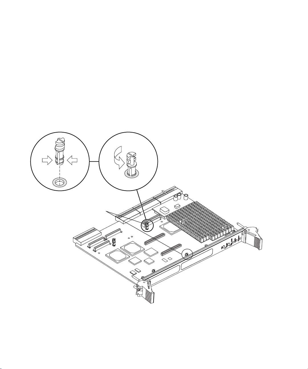
▼ To Install a Turret on a Netra CP2000/CP2100
Board for Double-Wide Memory Installation
Two turrets are pre-installed on the Netra CP2000/CP2100 board. Two additional
turrets must be added to the board before installing the double-wide memory
module. Turrets labeled 1 and 2 below are pre-installed on the board. Turrets labeled
3 and 4 below need to be installed.
● To install a turret onto the board, pinch the turret at the bottom and insert it into
the turret mounting hole on the Netra CP2000/CP2100 board as shown in
Follow the information and illustrations on turret rotation provided in the memory
module installation or removal procedures.
Turret 1
FIGURE 6.
Turret 3
Turret 2
Turret 4
FIGURE 6 Installation of a Turret on a Typical Netra CP2000/CP2100 Board for Double-
Memory Module Installation and Removal Guide for Netra CP2000/CP2100 Series cPCI Boards 15
wide Memory Module Installation

Note – This procedure can also be used for installing replacement turrets.
▼ To Install a Double-Wide Memory Module on a
Netra CP2000/CP2100 Board
Refer to FIGURE 7 and the following instructions to install the double-wide memory
module.
16 Memory Module Installation and Removal Guide • January 2003

1 2
cPCI
board
Turret
Connectors
Memory
module
3 4
Midway
notch
FIGURE 7 Double-wide Memory Module Installation Procedure on a Typical Netra
Caution – Follow the instructions below. If you don’t follow the installation
instructions properly, you can damage the connectors.
CP2000/CP2100 Board
!
1. Rotate the turrets to the position shown in
Memory Module Installation and Removal Guide for Netra CP2000/CP2100 Series cPCI Boards 17
FIGURE 7 Segment 1.

2. Grasp the memory module with two hands (see FIGURE 7 Segment 2).
3. Align the module connectors with the memory sockets on the Netra
CP2000/CP2100 board. Make sure the module is right side up so that the
connectors mate, and orient the midway notch on the memory module towards the
front panel of the cPCI board (see
4. Seat the module firmly into position so that it fits onto the board connectors,
while pressing down on the module with your fingers (see
The module connectors are fully engaged with the board connectors when you hear
or feel them snap into place.
FIGURE 7 Segment 2).
FIGURE 7 Segment 3).
Caution – Do not apply excessive pressure to connectors. Doing so may fracture the
connectors or the Netra circuit board.
!
The above procedure describes an installation of one memory module on to the
Netra CP2000/CP2100 board. If you wish to install a second memory module, follow
Step 1 to Step 4. The only difference is that you position the connectors of the second
memory module on the memory module connector sockets of the first module in a
piggy-back style, and then seat the connectors.
5. Rotate the turrets back to the position shown in
FIGURE 7 Segment 4.
18 Memory Module Installation and Removal Guide • January 2003

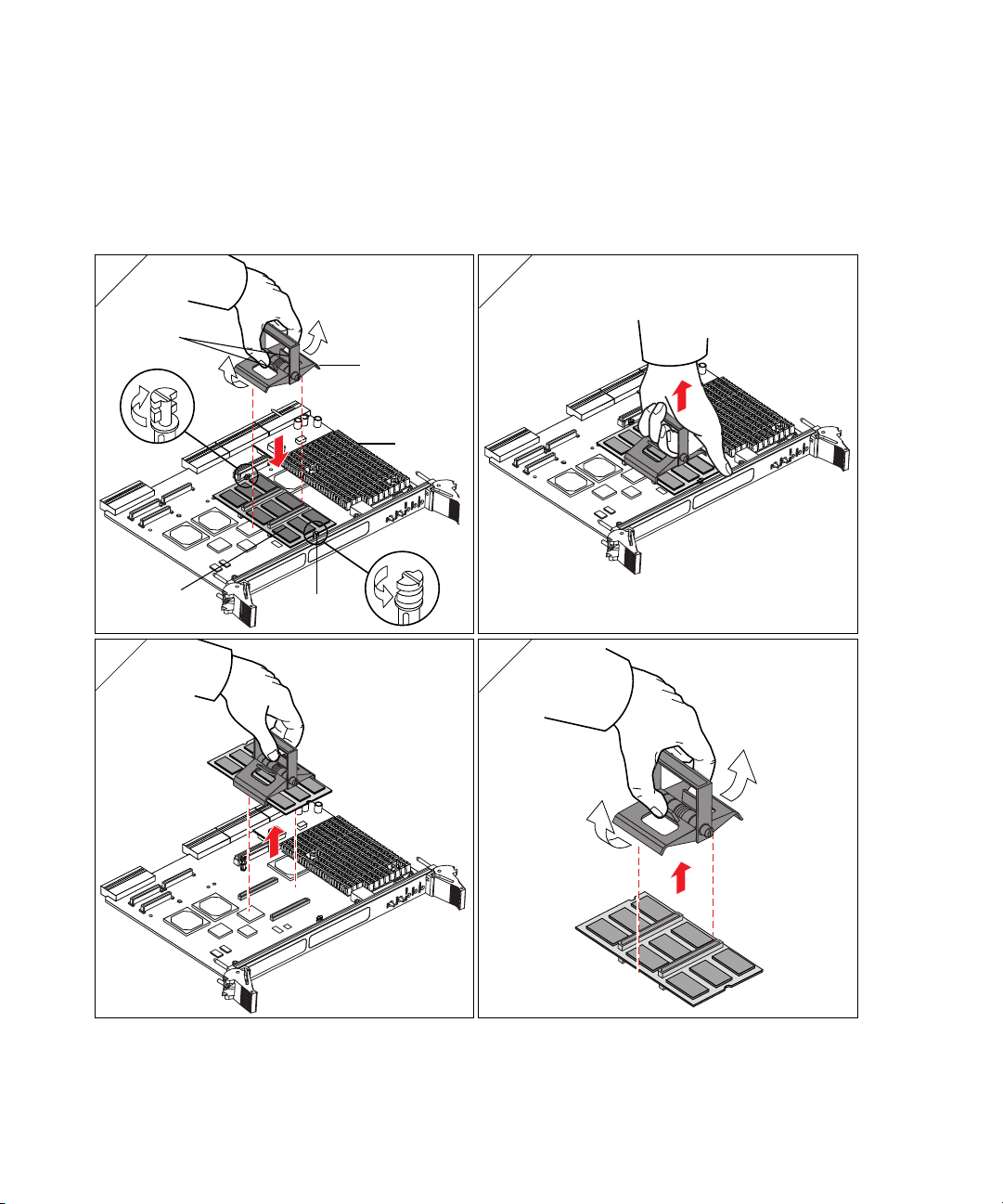
▼ To Remove a Double-Wide Memory Module
From a Netra CP2000/CP2100 Board
Refer to FIGURE 8 and the following instructions to remove the memory module.
1 2
cPCI
board
Turret
Memory
module
3 4
FIGURE 8 Double-wide Memory Module Extraction Procedure on a Typical Netra
CP2000/CP2100 Board
Front panel
Memory Module Installation and Removal Guide for Netra CP2000/CP2100 Series cPCI Boards 19

Caution – Follow the instructions below. If you don’t follow the removal
instructions properly, you can damage the connectors.
!
1. Rotate the turrets into the position shown in
2. Place your hands on the module, as shown in
3. Gently pry the module up, one connector at a time, starting from the side farthest
from the front panel (see
Use the hand closest to the front panel to hold the motherboard down while the
other hand is lifting the memory module off.
The above procedure describes an extraction of one memory module from a Netra
CP2000/CP2100 board. If you wish to extract two modules from the board, follow
Step 1 to Step 3. The only difference is that the connectors of the top memory
module are positioned on the memory module connector sockets of the bottom
module in a piggy-back style.
When two memory modules are installed on a Netra CP2000/CP2100 board, the
lower module might get extracted when removing the top module. If this happens,
separate the modules by gently prying the modules apart (see
Start with short ends of the modules. Try not to bend the modules, and use only
enough force to unmate the connectors.
Caution – Do not separate modules from each other by prying them apart at the
extremities, because you could damage the modules.
FIGURE 8 Segment 3).
FIGURE 8 Segment 1.
FIGURE 8 Segment 2.
FIGURE 8 Segment 4).
!
20 Memory Module Installation and Removal Guide • January 2003
 Loading...