

Sun Microsystems Netra 20, Netra 1120, Netra 1400, Netra 1125, Netra 1405 Installation Manual

Netra™ 20,
Netra t 1120/1125/1400/1405
Adjustable Rackmount
Installation Guide
For 19-inch Racks up to 800mm deep, including the
Sun 72-inch Expansion Rack
Sun Microsystems, Inc.
4150 Network Circle
Santa Clara, CA 95054 U.S.A.
650-960-1300
Part No. 806-3155-12
April 2002, Revision A
Send comments about this document to: docfeedback@sun.com

Copyright 2002Sun Microsystems, Inc.,4150 NetworkCircle, SantaClara, California95054, U.S.A.All rightsreserved.
Sun Microsystems, Inc.has intellectualproperty rightsrelating totechnology embodiedin theproduct that is described in this document. In
particular,and without limitation, these intellectual property rightsmay includeone ormore ofthe U.S.patents listedat
http://www.sun.com/patentsand oneor moreadditional patentsor pendingpatent applicationsin theU.S. andin othercountries.
This document and the productto whichit pertainsare distributedunder licensesrestricting theiruse, copying,distribution, and
decompilation. No part of the product orof thisdocument maybe reproducedin anyform byany meanswithout priorwritten authorizationof
Sun and its licensors, if any.
Third-partysoftware, includingfont technology,is copyrightedand licensedfromSun suppliers.
Parts of the product maybe derivedfrom BerkeleyBSD systems,licensed fromthe Universityof California.UNIX isa registeredtrademark in
the U.S. and in other countries, exclusively licensed throughX/Open Company,Ltd.
Sun, Sun Microsystems, theSun logo,AnswerBook2, docs.sun.com,and Solarisare trademarksor registeredtrademarks of Sun Microsystems,
Inc. in the U.S. and in other countries.
All SPARCtrademarks areused underlicense andare trademarksor registeredtrademarks ofSPARCInternational, Inc.in theU.S. andin other
countries. Products bearingSPARCtrademarks arebased uponan architecturedeveloped bySun Microsystems,Inc.
The OPEN LOOK and Sun™ Graphical User Interface was developed by Sun Microsystems,Inc. forits usersand licensees. Sunacknowledges
the pioneering effortsof Xeroxin researchingand developing the concept of visual or graphical user interfaces for the computer industry.Sun
holds a non-exclusive license fromXerox tothe XeroxGraphical UserInterface, whichlicense alsocovers Sun’slicensees whoimplement OPEN
LOOK GUIs and otherwise comply with Sun’s written license agreements.
Use, duplication, ordisclosure bythe U.S.Government issubject to restrictionsset forthin theSun Microsystems,Inc.license agreementsand as
providedin DFARS227.7202-1(a) and227.7202-3(a) (1995),DFARS252.227-7013(c)(1)(ii) (Oct.1998), FAR 12.212(a) (1995), FAR 52.227-19, or
FAR52.227-14 (ALT III), as applicable.
DOCUMENTATION IS PROVIDED "AS IS" AND ALL EXPRESS OR IMPLIED CONDITIONS, REPRESENTATIONS AND WARRANTIES,
INCLUDING ANYIMPLIED WARRANTYOF MERCHANTABILITY,FITNESS FORA PARTICULARPURPOSE ORNON-INFRINGEMENT,
ARE DISCLAIMED, EXCEPT TO THE EXTENT THAT SUCH DISCLAIMERS ARE HELD TO BE LEGALLY INVALID.
Copyright 2002 Sun Microsystems, Inc.,4150 NetworkCircle, SantaClara, California95054, Etats-Unis.Tousdroitsréservés.
Sun Microsystems, Inc.a lesdroits depropriété intellectuelsrelatants à la technologie incorporée dans le produit quiest décritdans ce
document. En particulier,et sans la limitation, ces droits depropriété intellectuelspeuvent inclureun ouplus desbrevetsaméricains énumérés
à http://www.sun.com/patentset unou lesbrevets plussupplémentaires oules applicationsde brevetenattente dansles Etats-Uniset dans
les autres pays.
Ce produit oudocument estprotégé parun copyrightet distribuéavec deslicences quien restreignentl’utilisation, la copie, la distribution, et la
décompilation. Aucune partie de ce produit oudocument nepeut êtrereproduite sous aucune forme, parquelquemoyen quece soit,sans
l’autorisation préalable et écrite de Sun et de ses bailleurs de licence, s’il y ena.
Le logiciel détenu par des tiers, et qui comprendla technologierelative auxpolices decaractères, estprotégé par un copyright et licencié par des
fournisseurs de Sun.
Des parties de ce produitpourront êtredérivées dessystèmes BerkeleyBSD licenciéspar l’Universitéde Californie.UNIX estune marque
déposée aux Etats-Unis et dans d’autres payset licenciéeexclusivement parX/Open Company,Ltd.
Sun, Sun Microsystems,le logoSun, AnswerBook2,docs.sun.com, etSolaris sontdes marquesde fabriqueou desmarques déposéesde Sun
Microsystems,Inc. auxEtats-Unis etdans d’autrespays.
Toutesles marquesSPARCsont utiliséessous licenceet sontdes marquesde fabrique ou des marquesdéposées deSPARCInternational, Inc.
aux Etats-Unis et dans d’autrespays. Lesproduits protantles marquesSPARCsont baséssur unearchitecture développéepar Sun
Microsystems,Inc.
L’interfaced’utilisation graphique OPEN LOOK et Sun™ a été développée par Sun Microsystems, Inc.pour sesutilisateurs etlicenciés. Sun
reconnaîtles effortsde pionniersde Xeroxpour larechercheet ledéveloppment duconcept desinterfaces d’utilisationvisuelle ougraphique
pour l’industrie de l’informatique. Sun détient une license non exclusive do Xerox surl’interface d’utilisationgraphique Xerox,cette licence
couvrant également les licenciées de Sun qui mettent en place l’interface d ’utilisation graphique OPEN LOOK et qui en outre seconforment
aux licences écrites de Sun.
LA DOCUMENTATION EST FOURNIE "EN L’ÉTAT" ET TOUTES AUTRES CONDITIONS, DECLARATIONS ET GARANTIES EXPRESSES
OU TACITESSONT FORMELLEMENTEXCLUES, DANSLA MESUREAUTORISEE PARLA LOIAPPLICABLE, YCOMPRIS NOTAMMENT
TOUTE GARANTIE IMPLICITE RELATIVE A LA QUALITE MARCHANDE, A L’APTITUDE A UNE UTILISATION PARTICULIERE OU A
L’ABSENCE DE CONTREFAÇON.
Please
Recycle

Contents
Rackmount Kit 2
Fitting the Slides to the System Chassis 3
▼ Fitting the Rack Brackets 11
Installation in a 19-inch Rack 13
Installing the System 16
Flange Mount Assemblies 18
Netra t 1400/1405 19
Netra 20/Netra T4 20
iii

iv Adjustable Rackmount Guide • April 2002

Figures
FIGURE 1 Dismantle the Slide 3
FIGURE 2 Fixing the Glides to the System Chassis (Netra t 1120/1125) 4
FIGURE 3 Fixing the Glides to the System Chassis (Netra t 1400/1405) 5
FIGURE 4 Fixing the Glides to the System Chassis (Netra 20/Netra T4) 6
FIGURE 5 Rack Bracket 7
FIGURE 6 Fitting the Brackets to the 72-inch Expansion Rack (covers shown removed for clarity) 10
FIGURE 7 Slide Fixing Points on the Rack Bracket 11
FIGURE 8 Fixing the Slides to the Rack Brackets 12
FIGURE 9 Securing the Brackets to the Rack 13
FIGURE 10 Securing the Slides to the Brackets 14
FIGURE 11 19-inch Rack Mounting Assembly 15
FIGURE 12 Sliding the System into the Rack (Netra t 1120/1125 and Sun 72-inch expansion rack
shown) 17
FIGURE 13 Flange Mount Assembly (Netra t 1400/1405) 19
FIGURE 14 Flange Mount Assembly (Netra 20/Netra T4) 20
v

vi Adjustable Rackmount Guide • April 2002

Tables
TABLE 1 Contents of the Adjustable Rackmount Kit 2
TABLE 2 Rack Fixing HolesUsed for Each Netra System 8
vii

viii Adjustable Rackmount Guide • April 2002

Adjustable Rackmount Installation
Guide
This guide describes the procedure for fitting the adjustable telescopic slide
rackmount kit to the following systems:
■ Netra t 1120
■ Netra t 1125
■ Netra t 1400
■ Netra t 1405
■ Netra 20/Netra T4
It also describes how to install these systems in a 19-inch rack up to 800mm in
depth, or a Sun 72-inch expansion rack, and how to fit the flange mount assemblies.
Note – The Netra 20 was originally known as the Netra T4.
The guide contains the following sections:
■ “Rackmount Kit” on page 2
■ “Fitting the Slides to the System Chassis” on page 3
■ “Installation in a 19-inch Rack” on page 13
■ “Installing the System” on page 16
■ “Flange Mount Assemblies” on page 18
1

Rackmount Kit
The kit contains the following items:
TABLE 1 Contents of the Adjustable Rackmount Kit
Description Qty Part Number
Sun slide mounting brackets 2 340-7056
Netra t 1400/1405 front slide bracket 2 340-6642
Netra t 1400/1405 rear slide bracket 2 340-6643
10-32 × 1/2-inch UNC panhead Phillips screws 12 240-1207
Telescopic slides 2 250-1505
M4 × 8mm panhead Phillips screws 20 240-1434
M4 × 10mm countersunk Phillips screws 4 240-3071
M5 × 10mm countersunk Phillips screws 6 240-3084
Chassis handle, 4U 2 340-4250
Chassis handle, straight 2 340-7212
Fixings for slide rack mount kit 1 370-4357
19-inch chassis mount flange (Netra t 1120/1125, Netra 20/Netra T4) 2 340-5434
19-inch chassis mount flange for adjustable rack (Netra t 1400/1405) 2 340-6901
Installation Guide (this document) 1 806-3155
2 Adjustable Rackmount Installation Guide • April 2002

Fitting the Slides to the System Chassis
1. Press in the button on the slide.
Refer to
FIGURE 1.
Slide (in two parts)
2
1
FIGURE 1 Dismantle the Slide
2. Pull the glide completely out of the slide.
3. Repeat for the other slide.
Glide
Adjustable Rackmount Installation Guide 3

4. Using four of the M4 × 8mm panhead Phillips screws supplied, screw the glide to
the side of the system chassis.
Refer to
FIGURE 2 (Netra t 1120/1125), FIGURE 3 (Netra t 1400/1405) or FIGURE 4
(Netra 20/Netra T4).
5. Repeat for the other glide.
FIGURE 2 Fixing the Glides to the System Chassis (Netra t 1120/1125)
4 Adjustable Rackmount Installation Guide • April 2002

FIGURE 3 Fixing the Glides to the System Chassis (Netra t 1400/1405)
Adjustable Rackmount Installation Guide 5

FIGURE 4 Fixing the Glides to the System Chassis (Netra 20/Netra T4)
6 Adjustable Rackmount Installation Guide • April 2002

Installation in a Sun 72-inch Expansion
Rack
The rack brackets are symmetrical and should be fitted to the rack with the arrow
pointing upwards, as shown in
FIGURE 5.
A
A
FIGURE 5 Rack Bracket
C
C
Netra t 1120/1125 and Netra 20/Netra T4
Fix the bracket to the right-hand side of the rack using the holes marked A in
FIGURE 4 (when viewed from the front).
Fix the backet to the left-hand side of the rack using the holes marked B in
Refer to
B
B
FIGURE 6 for an example.
A
C
C
A B
B
FIGURE 5.
Use eight 10-32 × 1/2-inch UNC panhead Phillips screws supplied in the kit, four for
each bracket. Refer to
Netra t 1400/1405
Fix the brackets to both sides of the rack using the holes marked C in FIGURE 5.
Use eight 10-32 × 1/2-inch UNC panhead Phillips screws supplied in the kit, four for
each bracket.
FIGURE 6 for an example.
Adjustable Rackmount Installation Guide 7

Fix the holes on the lower edge of the bracket to the holes in the side rack as shown
in
TABLE 2, which also shows the associated front rack lower fixing holes. Note that
the fixing holes on the rack are numbered from bottom to top.
TABLE 2 Rack Fixing HolesUsed for Each Netra System
Hole Number in Side Rack
Netra t 1120/1125
Hole # in Front Rack
9712
12 10 15
15 13 18
18 16 21
21 19 24
24 22 27
27 25 30
30 28 33
33 31 36
Netra 20/Netra T4 Netra t 1400/1405
36 34 39
39 37 42
42 40 45
45 43 48
48 46 51
51 49 54
54 52 57
57 55 60
60 58 63
63 61 66
66 64 69
69 67 72
72 70 75
75 73 78
78 76 81
81 79 84
84 82 87
8 Adjustable Rackmount Installation Guide • April 2002

TABLE 2 Rack Fixing HolesUsed for Each Netra System (Continued)
Hole Number in Side Rack
Netra t 1120/1125
Hole # in Front Rack
Netra 20/Netra T4 Netra t 1400/1405
87 85 90
90 88 93
93 91 96
96 94 99
99 97 102
102 100 N/A
1 Hole numbers 6/9, 102/105, 105/108 and 108/111 can also be used but are
usually occupied by top and bottom plastic inserts.
1
Adjustable Rackmount Installation Guide 9
Left-hand
bracket
Side rack
holes
Right-hand
bracket
Rear
Front rack
holes
FIGURE 6 Fitting the Brackets to the 72-inch Expansion Rack (covers shown removed for clarity)
10 Adjustable Rackmount Installation Guide • April 2002
Front

▼ Fitting the Rack Brackets
1. Fix the slides to the rack brackets using six of the M4 × 8mm panhead Phillips
screws supplied for each slide.
Refer to
FIGURE 7 and FIGURE 8. Use the holes marked L in FIGURE 7 to fix the left-
hand slide, and the holes marked
L
L
FIGURE 7 Slide Fixing Points on the Rack Bracket
L L
R
L
R to fix the right-hand slide.
R
L
RR
R
R
Adjustable Rackmount Installation Guide 11

FIGURE 8 Fixing the Slides to the Rack Brackets
2. Push the slides completely into the assembly on each side of the rack and release
the stop catches.
3. Mount the system in the rack as described in “Installing the System” on page 16.
12 Adjustable Rackmount Installation Guide • April 2002

Installation in a 19-inch Rack
The complete assembly is shown in FIGURE 11.
1. Decide on the vertical position in the rack at which you require the system to be
installed.
2. Attach a short bracket to each of the front rack uprights.
Use two of the brass M6 collar screws and M6 cage nuts, and one threaded strip, to
secure each bracket. Refer to
3. Attach a long bracket to each of the rear rack uprights.
Use two of the brass M6 collar screws and M6 cage nuts, and one threaded strip, to
secure each bracket. Refer to
FIGURE 9.
FIGURE 9.
Threaded
strip
Bracket
M6 collar
screw
(brass)
Rack upright
FIGURE 9 Securing the Brackets to the Rack
Adjustable Rackmount Installation Guide 13

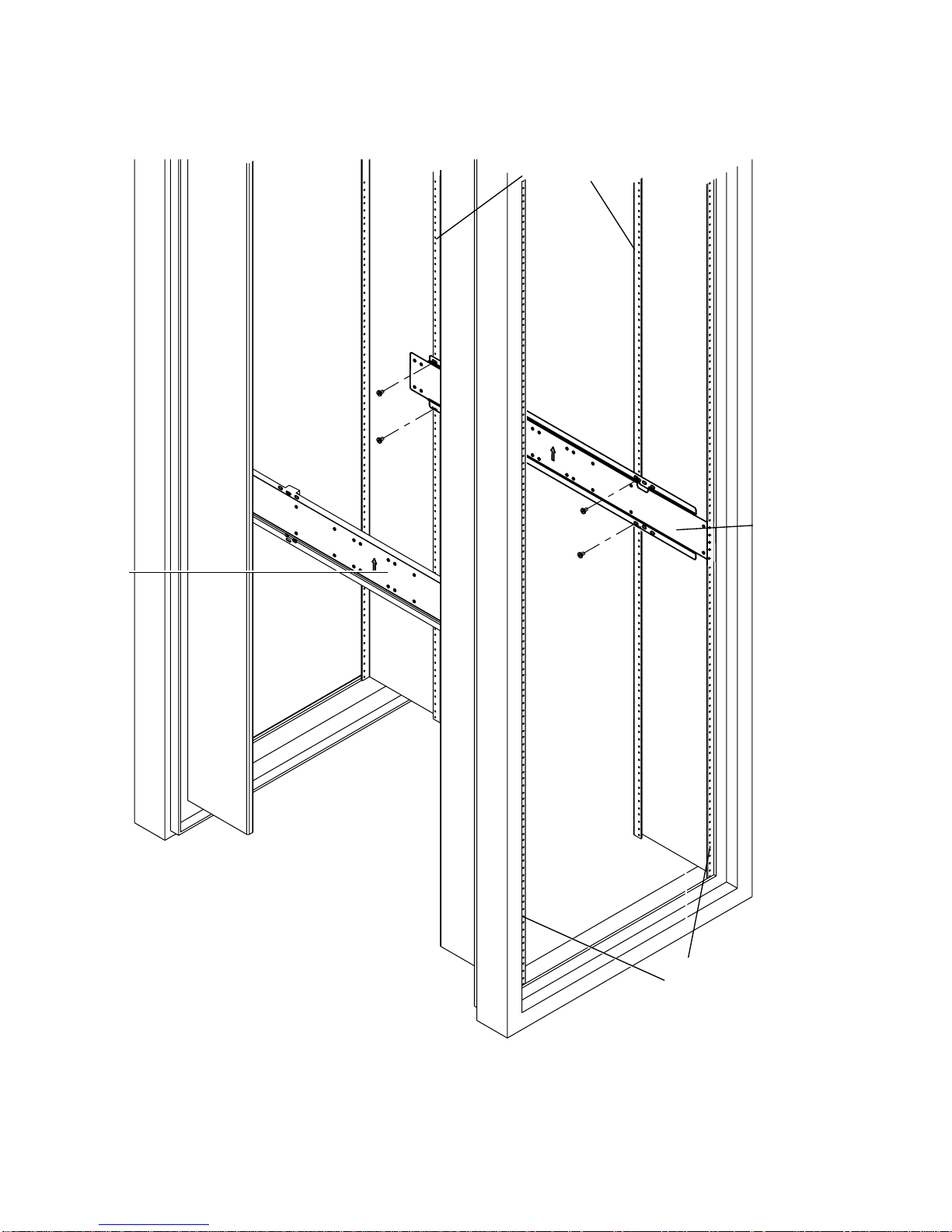
4. Extend the slides and secure the slides in the required position.
Use the M6 panhead screws from the inside and the M6 nuts, plain washers and star
washers from the outside. Refer to
FIGURE 10.
FIGURE 10 Securing the Slides to the Brackets
5. Push the slides completely into the assembly on each side of the rack and release
the stop catches.
6. Mount the system in the rack as described in “Installing the System” on page 16.
14 Adjustable Rackmount Installation Guide • April 2002

Rack upright
Short
bracket
Long
bracket
M6cage
nut
Rack
upright
M6 collar
screw
(brass)
M6 collar
screw
Threaded
strip
Threaded
strip
(brass)
FIGURE 11 19-inch Rack Mounting Assembly
Slide
Adjustable Rackmount Installation Guide 15

!
Installing the System
Caution – The system is heavy. In the following procedures, two people are
required to insert the system.
1. Align the inner glides attached to the system with the slide/bracket assemblies in
the rack.
2. Push in the slide buttons and slide the system all the way into the rack enclosure.
Refer to
FIGURE 12.
16 Adjustable Rackmount Installation Guide • April 2002

FIGURE 12 Sliding the System into the Rack (Netra t 1120/1125 and Sun 72-inch expansion rack shown)
Adjustable Rackmount Installation Guide 17

Flange Mount Assemblies
Chassis side panel
4 off M5x8 countersunk
Phillips screws per
flange (supplied)
Handle
(supplied)
FIGURE 13 Flange Mount Assembly (Netra t 1400/1405)
18 Adjustable Rackmount Installation Guide • April 2002
19-inch flange (supplied
2 off M4x10 countersunkPhillips screwsper
flange (supplied)

2 off M4x10 countersunk
Phillips screws per flange
(supplied)
3 off M5x8 countersunk Phillips screws
per flange (supplied)
FIGURE 14 Flange Mount Assembly (Netra 20/Netra T4)
Adjustable Rackmount Installation Guide 19

20 Adjustable Rackmount Installation Guide • April 2002
 Loading...