

Page 1

Sun Fire™V1280/Netra™1280
Systems Installation Guide
Sun Microsystems, Inc.
www.sun.com
Part No. 817-3334-10 (v2)
December 2003, Revision A
Submit comments about this document at: http://www.sun.com/hwdocs/feedback
Page 2

Copyright 2003Sun Microsystems, Inc.,4150 NetworkCircle, Santa Clara, California 95054, U.S.A. All rights reserved.
Sun Microsystems, Inc.has intellectualproperty rights relating to technology that is described in this document. In particular, and without
limitation, theseintellectual property rightsmay includeone ormore of the U.S. patents listed at http://www.sun.com/patentsand oneor
more additional patents or pending patent applications in the U.S. and in other countries.
This documentand theproduct to which it pertains are distributed under licenses restricting theiruse, copying,distribution, and
decompilation. Nopart ofthe product orof thisdocument maybe reproduced in any form by any means without prior written authorization of
Sun andits licensors,if any.
Third-party software, including font technology, is copyrighted and licensed fromSun suppliers.
Parts ofthe product maybe derivedfrom Berkeley BSD systems, licensed from the University of California. UNIX is aregistered trademarkin
the U.S.and inother countries,exclusively licensedthrough X/Open Company, Ltd.
Sun, SunMicrosystems, the Sun logo, AnswerBook2, docs.sun.com, Sun Fire, Netra, OpenBoot, and Solaris aretrademarks orregistered
trademarks ofSun Microsystems, Inc.in theU.S. andin othercountries.
All SPARC trademarksare usedunder licenseand are trademarksor registered trademarks of SPARCInternational, Inc.in theU.S. andin other
countries. Products bearingSPARC trademarksare based upon an architecturedeveloped bySun Microsystems, Inc.
The OPENLOOK andSun™ GraphicalUser Interfacewas developedby SunMicrosystems, Inc. for its users and licensees. Sun acknowledges
the pioneeringefforts of Xerox in researchingand developingthe conceptof visualor graphicaluser interfacesfor thecomputer industry. Sun
holds anon-exclusive licensefrom Xerox to the XeroxGraphical UserInterface, whichlicense alsocovers Sun’slicensees whoimplement OPEN
LOOK GUIsand otherwisecomply withSun’s writtenlicense agreements.
U.S. GovernmentRights—Commercial use. Government users are subject to the Sun Microsystems, Inc.standard licenseagreement and
applicable provisions ofthe FAR and its supplements.
DOCUMENTATION IS PROVIDED “AS IS” AND ALL EXPRESS OR IMPLIED CONDITIONS, REPRESENTATIONS AND WARRANTIES,
INCLUDING ANYIMPLIED WARRANTY OF MERCHANTABILITY,FITNESS FORA PARTICULAR PURPOSE OR NON-INFRINGEMENT,
ARE DISCLAIMED, EXCEPT TO THE EXTENT THAT SUCH DISCLAIMERS ARE HELD TO BE LEGALLY INVALID.
Copyright 2003Sun Microsystems, Inc.,4150 NetworkCircle, Santa Clara, Californie 95054, Etats-Unis. Tous droits réservés.
Sun Microsystems, Inc.a lesdroits de propriété intellectuels relatantsà latechnologie quiest décritdans cedocument. Enparticulier,et sansla
limitation, cesdroits de propriété intellectuels peuvent inclure unou plusdes brevetsaméricains énumérésà http://www.sun.com/patents et
un oules brevets plussupplémentaires ou les applications de brevet en attente dansles Etats-Uniset dansles autrespays.
Ce produit oudocument estprotégé par un copyright et distribué avec des licences qui en restreignent l’utilisation,la copie,la distribution,et la
décompilation. Aucunepartie dece produit oudocument nepeut être reproduite sous aucune forme, par quelque moyen que ce soit, sans
l’autorisation préalableet écritede Sunet deses bailleursde licence,s’il yena.
Le logicieldétenu pardes tiers,et quicomprend la technologie relative aux polices decaractères, estprotégé parun copyrightet licenciépar des
fournisseurs deSun.
Des partiesde ceproduit pourront êtredérivées dessystèmes BerkeleyBSD licenciéspar l’Universitéde Californie.UNIX estune marque
déposée auxEtats-Unis etdans d’autres payset licenciéeexclusivement parX/Open Company, Ltd.
Sun, SunMicrosystems, le logo Sun, AnswerBook2, docs.sun.com, Sun Fire, Netra, OpenBoot, et Solaris sontdes marquesde fabriqueou des
marques déposées de Sun Microsystems, Inc. aux Etats-Unis et dans d’autrespays.
Toutes lesmarques SPARCsont utiliséessous licenceet sontdes marques defabrique oudes marques déposéesde SPARC International,Inc.
aux Etats-Uniset dansd’autres pays. Les produits portant les marquesSPARC sontbasés surune architecture développée par Sun
Microsystems, Inc.
L’interfaced’utilisation graphiqueOPEN LOOKet Sun™a étédéveloppée parSun Microsystems, Inc.pour sesutilisateurs etlicenciés. Sun
reconnaît les efforts de pionniers de Xeroxpour larecherche et le développement du concept des interfaces d’utilisation visuelle ou graphique
pour l’industriede l’informatique.Sun détientune licensenon exclusivede Xerox surl’interface d’utilisationgraphique Xerox, cettelicence
couvrant égalementles licenciées deSun quimettent en placel’interface d’utilisation graphiqueOPEN LOOK etqui enoutre se conformentaux
licences écritesde Sun.
LA DOCUMENTATION EST FOURNIE "EN L’ÉTAT" ET TOUTES AUTRES CONDITIONS, DECLARATIONS ET GARANTIES EXPRESSES
OU TACITES SONT FORMELLEMENT EXCLUES, DANS LA MESURE AUTORISEEPAR LALOI APPLICABLE,Y COMPRIS NOTAMMENT
TOUTE GARANTIE IMPLICITE RELATIVE A LA QUALITE MARCHANDE, A L’APTITUDE A UNE UTILISATION PARTICULIERE OU A
L’ABSENCE DE CONTREFAÇON.
Please
Recycle
Page 3

Contents
Preface vii
1. Physical Installation 1–1
1.1 Installing Slides and Rails 1–2
1.1.1 Adjusting the Rail Assembly 1–2
1.1.2 Preparing the Rails for Two-Post Installations 1–3
1.1.3 Installing the Inner Slides on the System 1–4
1.1.4 Installing the Rail Assemblies in a Sun Fire/StoreEdge Cabinet 1–6
1.1.5 Installing the Rail Assemblies in a Sun Rack 900 Cabinet 1–8
1.1.6 Installing the Rail Assemblies in a 19-Inch Four-Post Cabinet 1–10
1.1.7 Installing the Rail Assemblies in a 19-inch Two-Post Rack 1–11
1.1.8 Assembling the Slide Assembly Lock (Netra only) 1–12
1.2 Installing the System in a Cabinet 1–13
1.2.1 Preparing to Install the System in the Cabinet 1–13
1.2.2 Mounting the System in the Cabinet 1–15
1.3 Installing the Locking Nuts (Netra only) 1–19
1-1
1-2
1-13
1-2
1-3
1-4
1-6
1-8
1-10
1-11
1-12
1-13
1-15
1-19
1.4 Installing the Cable Management Arm 1–20
1.4.1 Installing the CMA–Lite 1–22
1.4.2 Installing the CMA–800 1–23
1.5 Connecting Sun Fire V1280 Power Cables 1–25
1-20
1-22
1-23
1-25
iii
Page 4

1.6 Connecting Netra 1280 Power Cables 1–27
1-27
1.6.1 Assembling the Netra 1280 Power Connectors 1–27
1.6.2 Connecting the Netra 1280 Power Cables 1–29
1.6.3 Verifying the Power Input Connections Prior to the Initial Power
Application 1–29
1-29
1.7 Connecting Consoles to the System Controller 1–30
1.7.1 Connecting the Initial Administrative Console 1–30
1.7.2 Connecting the Administrative Console 1–32
1.8 Connecting the I/O Assemblies 1–32
1.9 Powering On the System 1–33
1.10 Powering Off the System 1–33
1-33
1-33
1.11 Installing Additional Hardware 1–34
1.12 Installing Additional Peripheral Devices 1–34
A. External Connections A–1
A-1
1-32
1-34
1-34
1-27
1-29
1-30
1-30
1-32
iv Sun Fire V1280/Netra 1280 Systems Installation Guide • December 2003
Page 5

Figures
FIGURE 1-1 Rail Assembly (Standard Configuration) 1–2
FIGURE 1-2 Rail Assembly (Modified for Two-Post Installation) 1–3
FIGURE 1-3 Spring Clips and Cutouts 1–5
FIGURE 1-4 Installing the Rails in a Sun Fire Cabinet 1–7
FIGURE 1-5 Installing the Rails in a Sun Rack 900 Cabinet or 19-Inch Four-Post Cabinet 1–9
FIGURE 1-6 Removing the Rail Assembly Slide Nuts 1–12
FIGURE 1-7 Fitting the Spacers 1–12
FIGURE 1-8 Releasing the Door Hinge Mechanism 1–13
FIGURE 1-9 Removing the Shipping Cradle Bolts 1–14
FIGURE 1-10 Inserting the Lifting Device into the Shipping Cradle 1–15
FIGURE 1-11 Aligning the Slides 1–16
FIGURE 1-12 Removing the Shipping Cradle 1–17
FIGURE 1-13 Pushing the System into the System Cabinet 1–18
FIGURE 1-14 Tightening the Securing Screws 1–18
FIGURE 1-15 Securing the Rear Slide Locking Nuts 1–19
1-5
1-12
1-16
1-17
1-18
1-2
1-3
1-7
1-9
1-12
1-13
1-14
1-15
1-18
1-19
FIGURE 1-16 Using the Torque Wrench to Secure the Slide Locking Nuts 1–20
FIGURE 1-17 Bracket Mounting Holes 1–21
FIGURE 1-18 CMA–Lite Cable Management Arm 1–22
FIGURE 1-19 Installing the Upper and Lower Pivot Bracket 1–23
FIGURE 1-20 Assembling the Upper and Lower Cable Arms 1–24
1-20
1-21
1-22
1-23
1-24
v
Page 6

FIGURE 1-21 DC Inlet Box With Source B Plastic Cover Removed and Connectors Exposed 1–28
1-28
FIGURE 1-22 Netra 1280 Power Feed Connectors 1–29
FIGURE 1-23 System Controller and I/O Assembly Locations 1–31
FIGURE A-1 External I/O Connections—Sun Fire V1280/Netra 1280 Systems (Rear View) A–1
FIGURE A-2 68-Pin SCSI Connector A–2
FIGURE A-3 DB-15 (Male) Alarms Service Port Connector A–4
FIGURE A-4 RJ-45 Serial Connectors A–5
FIGURE A-5 RJ-45 TPE Socket A–8
FIGURE A-6 RJ-45 Gigabit Ethernet Connectors A–9
A-2
A-5
A-8
1-29
1-31
A-1
A-4
A-9
vi Sun Fire V1280/Netra 1280 Systems Installation Guide • December 2003
Page 7

Preface
This guide describes how to install and set up a Sun Fire™ V1280/Netra™ 1280
systems.
Related Documentation
Application Title
Safety
Use
Use
Service
Sun Fire V1280/Netra 1280 Systems Compliance and Safety Manual
Sun Fire V1280/Netra 1280 System Administration Guide
Sun Fire V1280/Netra 1280 System Controller Command Reference Manual
Sun Fire V1280/Netra 1280 Systems Service Manual
Accessing Sun Documentation
You can view, print, or purchase a broad selection of Sun documentation, including
localized versions, at:
http://www.sun.com/documentation
vii
Page 8

Contacting Sun Technical Support
If you have technical questions about this product that are not answered in this
document, go to:
http://www.sun.com/service/contacting
Sun Welcomes Your Comments
Sun is interested in improving its documentation and welcomes your comments and
suggestions. You can submit your comments by going to:
http://www.sun.com/hwdocs/feedback
Please include the title and part number of your document with your feedback:
Sun Fire V1280/Netra 1280 Systems Installation Guide, part number 817-3334-10
Tools Required
For the procedures in this document, you will need these tools:
■ Computer lifting device
■ Screwdriver, Phillips no. 2
■ Wrench (remove adjustable bolts on slides)
■ Wrench (removing shipping cradle bolts)
■ Torque wrench and extension bar (Netra 1280 system only, supplied)
■ M5 nut spinner (Netra 1280 system only, supplied)
■ Crimp connectors 1-hole (Netra 1280 system only, supplied)
■ Crimp connectors 2-hole (Netra 1280 system only, supplied)
viii Sun Fire V1280/Netra 1280 Systems Installation Guide • December 2003
Page 9

CHAPTER
1
Physical Installation
This chapter describes how to install the system. It contains the following sections:
■ “Installing Slides and Rails” on page 1-2
■ “Installing the System in a Cabinet” on page 1-13
■ “Installing the Locking Nuts (Netra only)” on page 1-19
■ “Installing the Cable Management Arm” on page 1-20
■ “Connecting Sun Fire V1280 Power Cables” on page 1-25
■ “Connecting Netra 1280 Power Cables” on page 1-27
■ “Connecting Consoles to the System Controller” on page 1-30
■ “Connecting the I/O Assemblies” on page 1-32
■ “Powering On the System” on page 1-33
■ “Powering Off the System” on page 1-33
■ “Installing Additional Hardware” on page 1-34
■ “Installing Additional Peripheral Devices” on page 1-34
1-19
1-20
Caution – The Sun Fire V1280/Netra 1280 system, with mounting cradle, weighs
approximately 286 lbs (130 kg). Two people using a computer equipment lift are
required to move the system safely into the cabinet .
Caution – Pull only one Sun Fire V1280/Netra 1280 system out of the cabinet at a
time to prevent unbalancing the cabinet.
Caution – The cabinet stabilizers (if applicable) must be extended whenever a Sun
Fire V1280/Netra 1280 system is pulled out of the cabinet.
Note – For preinstalled systems use the instructions provided with the cabinet and
complete the installation at “Connecting Sun Fire V1280 Power Cables” on page 1-25
of this manual.
1-1
Page 10

1.1 Installing Slides and Rails
This section contains the following topics:
■ “Adjusting the Rail Assembly” on page 1-2
■ “Preparing the Rails for Two-Post Installations” on page 1-3
■ “Installing the Inner Slides on the System” on page 1-4
■ “Installing the Rail Assemblies in a Sun Fire/StoreEdge Cabinet” on page 1-6
■ “Installing the Rail Assemblies in a Sun Rack 900 Cabinet” on page 1-8
■ “Installing the Rail Assemblies in a 19-Inch Four-Post Cabinet” on page 1-10
■ “Installing the Rail Assemblies in a 19-inch Two-Post Rack” on page 1-11
■ “Assembling the Slide Assembly Lock (Netra only)” on page 1-12
1.1.1 Adjusting the Rail Assembly
Each rail assembly is comprised of four components (FIGURE 1-1):
■ Rear bracket that attaches to the slide assembly
■ Adjustable bracket that attaches to the rear bracket (adjustable bracket is not used
in some configurations)
■ Slide assembly (with inner and outer slides)
■ Front bracket
2-Post 3" Position
2-Post 4" Position
2-Post 6" Position
Sunfire Cabinet
bracket
NGR Cabinet
Storedge Cabinet
Adjustable
bracket
Rear
Slide
assembly
Front
bracket
FIGURE 1-1 Rail Assembly (Standard Configuration)
1-2 Sun Fire V1280/Netra 1280 Systems Installation Guide • December 2003
S
U
N
F
I
R
E
Page 11

Adjust the position of the rear bracket or the adjustable bracket to modify the length
of the assembly. The slide assembly and the rear bracket are marked with bracket
locations for specific cabinets stamped onto the metal.
FIGURE 1-1 shows the location
of the markings.
1.1.2 Preparing the Rails for Two-Post Installations
For two-post installations, you can dismantle and reassemble the rail assemblies
(
FIGURE 1-2). The rail assemblies can be adjusted to suit a 19-inch two-post rack that
has a post depth in the range of 3 to 6 inches (7.5 to 15.0 cm).
1. Remove the nuts that secure the adjustable bracket and discard the adjustable
bracket (
2. Remove the four nuts securing the front bracket.
FIGURE 1-1).
3. Rotate the front bracket 180 degrees and resecure it facing inward (
FIGURE 1-2).
4. Remove the four nuts that secure the rear bracket.
5. Rotate the rear bracket 180 degrees so that it faces inward (
FIGURE 1-2).
6. Align the rear bracket to the appropriate markings on the slide assembly and
resecure the rear bracket.
7. Repeat Step 1 through Step 6 for the second rail assembly.
Rear bracket
(facing inwards)
Front bracket
(facing inwards)
2-Post 3" Position
Slide assembly
2-Post 4" Position
Sunfire Cabinet
FIGURE 1-2 Rail Assembly (Modified for Two-Post Installation)
2-Post 6" Position
NGR Cabinet
Storedge Cabinet
Chapter 1 Physical Installation 1-3
Page 12

1.1.3 Installing the Inner Slides on the System
1. Remove the inner slide from the slide assembly:
a. Press the latch adjacent to the green latch.
b. Pull the inner slide free from the outer slide/rail assembly.
2. Push up on the inner slide so that the locating tab, on the side of the system, clips
over the cutouts in the slide (
The spring tab should engage.
Note – The spring clips must be above the system hooks; the lip on the main body
of the inner slide must engage under and behind the system hook.
3. Secure the inner slide to the system using two no. 8-32-inch screws for each slide.
4. Repeat Step 1 through Step 3 for the second inner slide.
FIGURE 1-3).
1-4 Sun Fire V1280/Netra 1280 Systems Installation Guide • December 2003
Page 13

FIGURE 1-3 Spring Clips and Cutouts
Chapter 1 Physical Installation 1-5
Page 14

1.1.4 Installing the Rail Assemblies in a Sun
Fire/StoreEdge Cabinet
Sun Fire/StoreEdge™ cabinets have no. 10-32 UNF tapped screw holes in the front
and rear, which are numbered from bottom to top.
Note – The rail assemblies are reversible. They can be used on either side of the
cabinet.
1. Adjust the position of the adjustable bracket on each rail assembly.
a. Loosen the two nuts that secure the adjustable bracket.
b. Reposition the adjustable bracket to the location stamped ‘SUNFIRE’ on the
rear bracket and resecure the adjustable bracket.
2. Adjust the length of each rail assembly.
a. Loosen the four nuts that secure the rear bracket.
b. Reposition the rear bracket to the location marked ‘Sun Fire Cabinet’ on the
slide assembly and resecure the rear bracket.
1.1.4.1 Installing the Rail Assemblies in the Bottom Position
1. Insert the pins in the front bracket into cabinet holes 22 and 33 (FIGURE 1-4).
The pins will hold the bracket in place until the bracket is secured.
2. Secure the adjustable bracket into cabinet holes 24 and 31 with two no. 10-32 UNF
screws.
3. Secure the front bracket into cabinet holes 24 and 31 with two no. 10-32 UNF
screws.
4. Repeat Step 1 through Step 3 for the second rail assembly.
1-6 Sun Fire V1280/Netra 1280 Systems Installation Guide • December 2003
Page 15

1.1.4.2 Installing the Rail Assemblies in the Top Position
1. Insert the pins in the front bracket into cabinet holes 58 and 69 (FIGURE 1-4).
The pins will hold the bracket in place until it is secured.
2. Secure the adjustable bracket into cabinet holes 60 and 67 with two no. 10-32 UNF
screws.
3. Secure the front bracket into cabinet holes 60 and 67 with two no. 10-32 UNF
screws.
4. Repeat Step 1 through Step 3 for the second rail assembly.
FIGURE 1-4 Installing the Rails in a Sun Fire Cabinet
Front bracket
secured to outer cabinet holes
Adjustable bracket
secured to inner cabinet holes
Chapter 1 Physical Installation 1-7
Page 16

1.1.5 Installing the Rail Assemblies in a Sun Rack 900
Cabinet
Sun Rack 900 cabinets have M-6 UNF tapped screw holes in the front and rear that
are numbered from bottom to top.
Note – The rail assemblies are reversible. They can be used on either side of the
cabinet.
1. Remove the adjustable bracket on each rail.
a. Loosen the two nuts that secure the adjustable bracket.
b. Discard the adjustable bracket.
2. Adjust the length of each rail assembly.
a. Loosen the four nuts that secure the rear bracket.
b. Reposition the rear bracket to the location marked ‘NGR Cabinet’ on the slide
assembly and resecure the rear bracket.
1.1.5.1 Installing the Rail Assemblies in the Bottom Position
1. Insert the pins in the front bracket into cabinet holes 22 and 33 (FIGURE 1-5).
The pins will hold the bracket in place until the bracket is secured.
2. Secure the rear bracket into cabinet holes 24 and 31 with two M-6 UNF screws.
3. Secure the front bracket into cabinet holds 24 and 31 with two M-6 UNF screws.
4. Repeat Step 1 through Step 3 for the second rail assembly.
1.1.5.2 Installing the Rail Assemblies in the Top Position
1. Insert the pins in the front bracket into cabinet holes 58 and 69 (FIGURE 1-5).
The pins will hold the bracket in place until the bracket is secured.
2. Secure the rear bracket into cabinet holes 60 and 67 with two M-6 UNF screws.
3. Secure the front bracket into cabinet holes 60 and 67 with two M-6 UNF screws.
4. Repeat Step 1 through Step 3 for the second rail assembly.
1-8 Sun Fire V1280/Netra 1280 Systems Installation Guide • December 2003
Page 17

Front bracket
secured to outer cabinet holes
FIGURE 1-5 Installing the Rails in a Sun Rack 900 Cabinet or 19-Inch Four-Post Cabinet
Rear bracket
secured to outer cabinet holes
Chapter 1 Physical Installation 1-9
Page 18

1.1.6 Installing the Rail Assemblies in a 19-Inch FourPost Cabinet
The rails can be adjusted to suit a 19-inch cabinet that is compliant with either IEC
297-4 or EIA 310-D. Each rail assembly has a distance between front and rear
mounting rails from 17.7 to 30.7 inches (45.0 to 78.0 cm).
Note – The rail assemblies are reversible. They can be used on either side of the
cabinet.
Caution – It is the installer’s responsibility to ensure that the cabinet has sufficient
structural strength and stability to handle any required installations.
1. Remove the adjustable bracket on each rail assembly.
a. Loosen the two nuts that secure the adjustable bracket.
b. Discard the adjustable bracket.
2. Adjust the length of each rail assembly.
a. Loosen the four nuts that secure the rear bracket.
b. Reposition the rear bracket to the appropriate markings shown on the slide
assembly and resecure the rear bracket.
3. Secure the rear bracket with two no. 10-32 UNF screws (
■ To install the system in the lowest position, insert the rackmount securing screws
no lower than 18.5 inches and 22.5 inches (47.0 cm and 57.2 cm) respectively.
Refer to the Sun Fire V1280/Netra 1280 Slide Rail Installation Instructions and
Mounting Template to determine cabinet hole locations.
■ To install the system in the topmost position, insert the rackmount securing screws
no higher than 39.5 inches and 43.5 inches (100.0 cm and 110.0 cm) respectively.
Refer to the Sun Fire V1280/Netra 1280 Slide Rail Installation Instructions and
Mounting Template to determine cabinet hole locations.
4. Secure the front bracket with two no. 10-32 UNF screws (
5. Repeat Step 1 through Step 4 for the second rail assembly.
FIGURE 1-5).
FIGURE 1-5).
1-10 Sun Fire V1280/Netra 1280 Systems Installation Guide • December 2003
Page 19

1.1.7 Installing the Rail Assemblies in a 19-inch TwoPost Rack
Note – The rails assemblies must be prepared. See “Preparing the Rails for Two-Post
Installations” on page 1-3.
Note – The rail assemblies are reversible. They can be used on either side of the
cabinet.
Caution – Ensure that the rack is anchored to the floor, ceiling, or to adjacent
frames. It is the installer’s responsibility to ensure that the rack has sufficient
structural strength and stability to handle any required installations.
1. Secure the front bracket with two no. 10-32 UNF screws.
Insert the rackmount securing screws no lower than 18.5 inches and 22.5 inches (47.0
cm and 57.2 cm) respectively. Refer to the Sun Fire V1280/Netra 1280 Slide Rail
Installation Instructions and Mounting Template to determine cabinet hole locations.
2. Secure the rear bracket with two no. 10-32 UNF screws.
3. Repeat Step 1 and Step 2 for the second rail assembly.
Chapter 1 Physical Installation 1-11
Page 20

1.1.8 Assembling the Slide Assembly Lock (Netra only)
1. Remove the nuts at the rear of each slide assembly (FIGURE 1-6).
FIGURE 1-6 Removing the Rail Assembly Slide Nuts
2. Secure a spacer, finger tight, to each of the studs with the flange side towards the
slide (
FIGURE 1-7 Fitting the Spacers
FIGURE 1-7).
Note – The remaining slide assembly lock installation occurs after the system is
mounted in the cabinet.
1-12 Sun Fire V1280/Netra 1280 Systems Installation Guide • December 2003
Page 21

1.2 Installing the System in a Cabinet
This section contains the following topics:
■ “Preparing to Install the System in the Cabinet” on page 1-13
■ “Mounting the System in the Cabinet” on page 1-15
1.2.1 Preparing to Install the System in the Cabinet
1. Remove the front bezel doors (FIGURE 1-8).
a. Open the door and press down on the hinge pin levers to release the hinges.
b. Lift the door off of the hinge pins and store the door in a safe place.
c. Repeat Step a and Step b for the second front bezel door.
FIGURE 1-8 Releasing the Door Hinge Mechanism
Chapter 1 Physical Installation 1-13
Page 22

2. Remove the shipping cradle bolts (FIGURE 1-9).
The bolts secure the orange metal shipping cradle to the wooden pallet.
FRONT
FIGURE 1-9 Removing the Shipping Cradle Bolts
1-14 Sun Fire V1280/Netra 1280 Systems Installation Guide • December 2003
Page 23

1.2.2 Mounting the System in the Cabinet
Caution – The Sun Fire V1280/Netra 1280 system with mounting cradle weighs
approximately 286.0 lbs (130.0 kg). To prevent personal injury, two people are
needed to move the system safely into the cabinet using a computer equipment lift.
1. Extend the cabinet stabilizer and lock it in position (as applicable).
Caution – The shipping cradle must be attached when the system is lifted. Failure
to do so will result in major damage to the system.
2. Insert the forks of the lifting device fully through the shipping cradle opening
FIGURE 1-10).
(
FIGURE 1-10 Inserting the Lifting Device into the Shipping Cradle
FRONT
Chapter 1 Physical Installation 1-15
Page 24

3. Lift the system off of the wooden shipping pallet and remove the pallet.
4. Extend the outer slides from the cabinet and latch them in the extended position.
5. Lift the system until it is level with the outer slides on the cabinet.
6. Carefully move the lifting device forward until the slides on the system are fully
engaged with the outer slides on the cabinet
(FIGURE 1-11).
The latches on each side must click out, locking the slides.
Outer slides
FIGURE 1-11 Aligning the Slides
Inner slides
1-16 Sun Fire V1280/Netra 1280 Systems Installation Guide • December 2003
Page 25

Caution – The cabinet stabilizers (if applicable) must be extended or the cabinet
might topple when the lifting device is withdrawn.
7. With the lifting device still supporting the system, loosen the four captive screws
attaching the handles of the shipping cradle to the system.
8. Pull both shipping cradle handles away from the system.
This disconnects the shipping cradle from the system.
9. Lower the shipping cradle out of the way with the lifting device.
Store the shipping cradle for future use.
FIGURE 1-12 Removing the Shipping Cradle
Chapter 1 Physical Installation 1-17
Page 26

10. Press the green latches on each slide and push the system into the cabinet
(
FIGURE 1-13).
FIGURE 1-13 Pushing the System into the System Cabinet
11. Tighten the two securing screws on the front of the system to secure the system in
the cabinet (
FIGURE 1-14).
12. Retract the cabinet stabilization mechanism (as required).
13. Reattach the front doors of the system.
Securing screw Securing screw
FIGURE 1-14 Tightening the Securing Screws
1-18 Sun Fire V1280/Netra 1280 Systems Installation Guide • December 2003
Page 27

1.3 Installing the Locking Nuts (Netra only)
Note – It is essential that the locking nuts are securely fitted for the system to
comply with NEBS Level 3 vibration requirements.
1. Secure the locking nuts onto the studs at the rear of the slide assemblies
FIGURE 1-15).
(
The round end should be oriented toward the spacers.
FIGURE 1-15 Securing the Rear Slide Locking Nuts
Caution – The torque wrench handle will release suddenly once the correct torque
is reached. Take care to keep your hand clear of the system and the cabinet to avoid
injury.
2. Use the torque wrench and extension attached to the rear of the system to tighten
the nuts.
The torque wrench is preset to 88.5 inch lbs (10 Nm). If the ratchet needs to be
reversed, remove the cap and refit onto the opposite side. The nuts are fully
tightened when the wrench handle releases (
FIGURE 1-16).
Chapter 1 Physical Installation 1-19
Page 28

Ratchet reversing cap
FIGURE 1-16 Using the Torque Wrench to Secure the Slide Locking Nuts
3. Replace the torque wrench and extension on their mountings on the rear of the
system and fasten the securing strap.
1.4 Installing the Cable Management Arm
This section contains the following topics:
■ “Installing the CMA–Lite” on page 1-22
■ “Installing the CMA–800” on page 1-23
The purpose of a cable management arm is to support and protect cables when a
system slides into or out of a cabinet.
Two cable management arm solutions are offered: CMA-Lite and CMA-800. The
optimum choice of CMA is dependant upon the available depth in the cabinet and
the quantity or type of cable to be supported. Use the CMA-Lite if the larger CMA800 management arm does not fit your cabinet.
Threaded holes for attaching the CMA are provided on the rear of the system
(
FIGURE 1-17).
1-20 Sun Fire V1280/Netra 1280 Systems Installation Guide • December 2003
Page 29

Upper
bracket holes
Lower
bracket holes
PCI 1
PCI 0
33MHz
33MHz
SSC1 SSC1
BB
A
Serial A Serial B
SCSI3
PCI 3
PCI 2
PCI 4
PCI 5
33MHz
33MHz
33MHz
66MHz
ALARMS
Link
Active
NET
0
GBit
Link
Active
NET
1
GBit
AC
3
SOURCE A
SOURCE B
AC
2
AC
1
SOURCE A
AC
0
FIGURE 1-17 Bracket Mounting Holes
Chapter 1 Physical Installation 1-21
Page 30
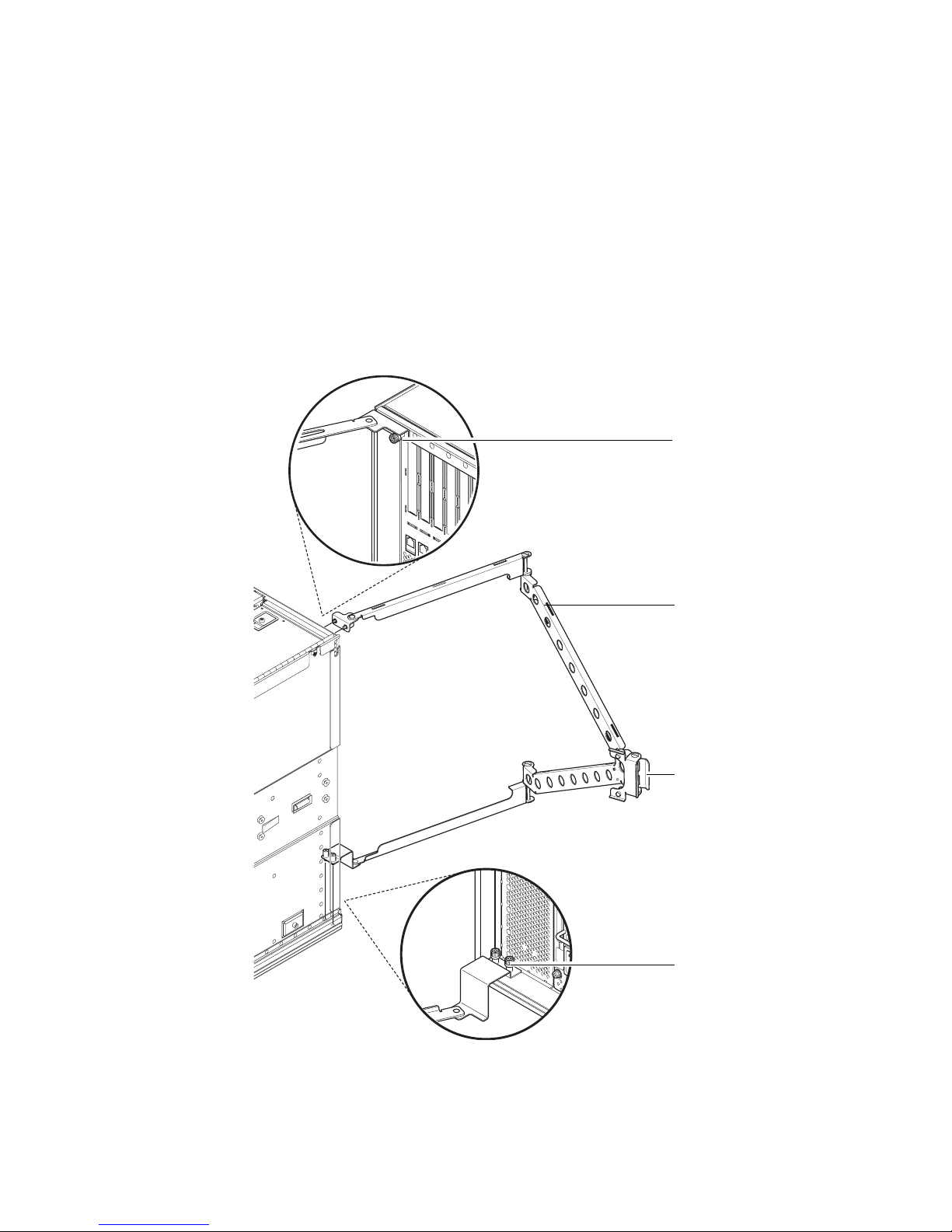
1.4.1 Installing the CMA–Lite
1. Secure the pivot at the end of the upper arm to the top rear of the system using the
two captive screws (
2. Secure the center pivot point of the CMA to the inside rear of the left hand rail
assembly using the two captive screws.
3. Secure the pivot at the end of the lower arm to the bottom rear of the system using
the two captive screws.
FIGURE 1-18).
Captive
screws (2)
CMA-Lite
FIGURE 1-18 CMA–Lite Cable Management Arm
1-22 Sun Fire V1280/Netra 1280 Systems Installation Guide • December 2003
Captive
screws (2)
Captive
screws (2)
Page 31

1.4.2 Installing the CMA–800
1. Remove the hinge pin to the upper pivot bracket of the I/O cable arm.
2. Remove the hinge pin from the lower pivot bracket of the power cable arm
(
FIGURE 1-19).
3. Secure the upper pivot bracket to the system using the two captive screws
(
FIGURE 1-19).
4. Secure the lower pivot bracket using the two captive screws (
Captive screws (2)
Upper pivot bracket
Lower pivot bracket
Captive screws (2)
FIGURE 1-19).
FIGURE 1-19 Installing the Upper and Lower Pivot Bracket
5. Secure the t-brackets to the cabinet rails using the two captive screws.
The t-brackets are marked to indicate which mounts on the left and which mounts
on the right.
Chapter 1 Physical Installation 1-23
Page 32

6. Secure the I/O cable arm to the top of the left t-bracket using the two captive
screws.
7. Secure the power cable arm to the bottom of the left t-bracket using the two
captive screws.
8. Reconnect the I/O cable arm to the upper pivot bracket and secure it by restoring
the hinge pin (
FIGURE 1-20).
9. Reconnect the power cable arm to the lower pivot bracket and secure it by
restoring the hinge pin. (
FIGURE 1-20).
FIGURE 1-20 Assembling the Upper and Lower Cable Arms
1-24 Sun Fire V1280/Netra 1280 Systems Installation Guide • December 2003
Page 33

1.5 Connecting Sun Fire V1280 Power
Cables
Caution – The Sun Fire V1280 system is designed to work with power systems
having a grounded neutral conductor. Do not connect the equipment into any other
type of power system. Contact your facilities manager or a qualified electrician to
determine what type of power is supplied to your building.
Caution – Your Sun product is shipped with grounding type (three-wire) power
cords. Always connect the cords into a grounded power outlet.
Caution – The socket outlets must be near the equipment and easily accessible.
1. Turn the system power switch to the Standby position.
Caution – The On/Standby power switch does not isolate the equipment. The AC
power cords are the primary means of disconnection for this product.
2. Turn the cabinet power off (in a powered cabinet).
Refer to the installation guide that came with the cabinet.
3. Label both ends of the power cords.
Two cords should be labelled Source A and two should be labelled Source B.
4. Connect the power cables to the system.
a. Connect the Source A power cords to AC0 and AC1 on the system and the
Source B power cords to AC2 and AC3 on the system.
b. Run the power cords through the CMA and secure them with tie-wraps.
Make sure the CMA can extend and retract without dislodging the power cords.
Note – Step 3 and Step 4 will already be completed for systems that come
preinstalled in a Sun Rack 900 cabinet.
Chapter 1 Physical Installation 1-25
Page 34

5. Connect the system to the power source.
If mounted in an unpowered cabinet:
i. Connect power cords from Source A on the system to the customer-supplied
power source A circuit breakers.
ii. Connect power cords from Source B on the system to the customer-supplied
power source B circuit breakers.
If mounted in a powered cabinet:
i. Connect power cords from Source A on the cabinet to the customer-supplied
power source A circuit breakers and Source B on the cabinet to the customersupplied power source B circuit breakers.
Refer to the installation guide that came with the cabinet for instructions on
cabinet power cabling.
Note – It is the installer’s responsibility to ensure that the cabinet has sufficient
electrical power and redundancy to handle the required installation.
ii. Connect power cords from Source A on the cabinet to Source A on the
system and Source B on the cabinet to the Source B on the system.
Refer to the installation guide that came with the cabinet for instructions on
cabinet power cabling.
1-26 Sun Fire V1280/Netra 1280 Systems Installation Guide • December 2003
Page 35

1.6 Connecting Netra 1280 Power Cables
This section contains the following topics:
■ “Assembling the Netra 1280 Power Connectors” on page 1-27
■ “Connecting the Netra 1280 Power Cables” on page 1-29
■ “Verifying the Power Input Connections Prior to the Initial Power Application”
on page 1-29
1.6.1 Assembling the Netra 1280 Power Connectors
1. Turn the power switch to the Standby position.
Caution – The On/Standby power switch does not isolate the equipment. The
circuit breakers are the primary means of disconnection for this product.
2. Remove the plastic covers from the DC inlet box (
Each cover is retained by a Phillips no. 2 screw.
3. Assemble the earth connection.
a. Crimp the two-hole earth lug onto the earth cable.
The shipping kit contains lugs for crimping customer-supplied cables. Use a
crimping tool or approved equivalent to secure the lugs onto the cables.
b. Use two M5 nuts and washers to fit the lug to the location between the two
plastic covers using the M5 nut spinner provided.
4. Assemble the power cable ends.
a. Crimp the single-hole lugs onto the input and return cables.
b. Slide the lugs through the plastic cover.
c. Ensure that the cables are oriented correctly with respect to the labeling on the
connection studs.
d. Ensure that the correct polarity of feed is connected to each stud on the rear of
the system.
e. Ensure that an earth strap for each feed pair is connected to the electrical earth
studs (
FIGURE 1-21).
FIGURE 1-21).
5. Secure the plastic covers with the Phillips no. 2 screws.
Chapter 1 Physical Installation 1-27
Page 36

Source B+
White
(neutral/return)
Source BBlack
(hot/input)
Source B+
White
(neutral/return)
Source BBlack
(hot/input)
Electrical
grounding studs
Plastic cover
retaining screw
Plastic cover
FIGURE 1-21 DC Inlet Box With Source B Plastic Cover Removed and Connectors Exposed
1-28 Sun Fire V1280/Netra 1280 Systems Installation Guide • December 2003
Page 37

1.6.2 Connecting the Netra 1280 Power Cables
1. Connect the earthground cable to a suitable ground point.
2. Connect the remaining power cables to the customer-supplied circuit breakers.
DC0 and DC1 are connected to one power source, and DC2 and DC3 to the other
(
FIGURE 1-22).
Source B
Source A
+
-
+
-
+
-
+
-
FIGURE 1-22 Netra 1280 Power Feed Connectors
Circuit breaker
Circuit breaker
Circuit breaker
Circuit breaker
White (neutral/return)
Black (hot/input)
White (neutral/return)
Black (hot/input)
White (neutral/return)
Black (hot/input)
White (neutral/return)
Black (hot/input)
DC3 (B +)
DC3 (B -)
DC2 (B +)
DC2 (B -)
Netra 1280
Earth ground
DC1 (A +)
DC1 (A -)
DC0 (A +)
DC0 (A -)
1.6.3 Verifying the Power Input Connections Prior to
the Initial Power Application
Caution – Ensure the cabling is correct prior to switching system power on for the
first time. Incorrect cabling could cause injury to personnel or damage to equipment.
1. Verify the ground input wires (green) connect to system ground.
2. Verify the hot input wires (black) connect to negative terminal lugs.
3. Verify the neutral-return input wires (white) connect to positive terminal lugs.
Connect a digital volt meter to each branch in turn and verify:
■ DVM ground probe-to-system ground and red probe to + (positive) terminals
indicates 0 VDC.
■ DVM ground probe-to-system ground and - (negative) terminals indicates -48
VDC.
Chapter 1 Physical Installation 1-29
Page 38

1.7 Connecting Consoles to the System
Controller
This section contains the following topics:
■ “Connecting the Initial Administrative Console” on page 1-30
■ “Connecting the Administrative Console” on page 1-32
The system controller (SC) is responsible for providing the Lights-Out Management
(LOM) functions, which include power on sequencing, sequencing module power-on
self-tests (POST), environmental monitoring, fault indication and alarms.
The LOM command line interface and the Solaris/OpenBoot™ PROM console are
accessed by connecting an administrative console to either serial port A or the
10/100 LOM Ethernet port. The administrative console can be any external input
device (laptop computer or workstation) connected to either of these ports.
Serial port A is used to connect directly to an ASCII terminal or a network terminal
server (NTS) using a command line interface. This port is used for the initial
administrative console. It is used to modify the default system controller settings
(usually so that the 10/100 LOM Ethernet port can be used as an administrative
console). The configuration of Serial port A cannot be changed.
The 10/100 LOM Ethernet port is used to connect the system controller to the
network. This port is preconfigured as follows:
■ System controller configured to be on a network
■ System controller Ethernet configured for dynamic host configuration protocol
(DHCP).
■ No pre-configured system controller Ethernet IP address, Gateway, DNS domain,
DNS servers
1.7.1 Connecting the Initial Administrative Console
For the initial configuration, connect Serial A port to the serial port on any of the
following devices:
■ ASCII terminal
■ Sun workstation
■ Terminal server (or patch panel connected to a terminal server)
Note – If the IP address assigned to the 10/100 LOM Ethernet port by DHCP is
known, the 10/100 LOM Ethernet port can be accessed without the Serial A port.
1-30 Sun Fire V1280/Netra 1280 Systems Installation Guide • December 2003
Page 39

1. Connect the administrative console to the Serial A port.
The Serial A port is a DTE (data terminal equipment) port. An adapter, cross-over or
null modem cable is required to connect the Serial A port to another DTE port. For
Serial A port connector pinouts and adaptor information, see “LOM Serial Ports” on
page A-5).
2. Turn the customer-supplied circuit breakers power switch to the On position.
3. Turn the system power switch to the On position.
Refer to the Sun Fire V1280/Netra 1280 System Administration Guide Administration
Guide.
4. Set up the administrative console.
Refer to the Sun Fire V1280/Netra 1280 System Administration Guide.
I/O Assembly
68-pin SCSI port
Alarms port
Serial A port
10/100 LOM
Ethernet port
Net0/Net1
Ethernet port
PCI 1
PCI 2
PCI 0
33MHz
33MHz
33MHz
SSC1 SSC1
BB
A
Serial A Serial B
SCSI3
PCI 3
PCI 4
PCI 5
33MHz
33MHz
66MHz
ALARMS
Link
Active
NET
0
GBit
Link
Active
NET
1
GBit
AC
3
SOURCE A
SOURCE B
AC
2
AC
1
SOURCE A
AC
0
FIGURE 1-23 System Controller and I/O Assembly Locations
Chapter 1 Physical Installation 1-31
Page 40

1.7.2 Connecting the Administrative Console
Once the initial configuration is complete, you can perform system administration
tasks directly or over the network using the 10/100 LOM Ethernet port.
Note – Communication on the Serial A port is possible but is subject to interruption
by the LOM device. Refer to the Sun Fire V1280/Netra 1280 System Administration
Guide.
1. Connect the 10/100 LOM Ethernet port to the chosen administrative console (local
hub, router, or switch).
For 10/100 LOM Ethernet
Port” on page A-8.
2. Set up the chosen administrative console.
Refer to the Sun Fire V1280/Netra 1280 System Administration Guide.
port connector information, see “10/100 LOM Ethernet
1.8 Connecting the I/O Assemblies
The I/O assemblies provide network interface and peripheral access to the system
domains.
1. Connect one end of the I/O Ethernet cable to the Net0/Net1 Ethernet port
(
FIGURE 1-23).
2. Connect the other end of the I/O Ethernet cable to the hub, workstation, or
peripheral.
1-32 Sun Fire V1280/Netra 1280 Systems Installation Guide • December 2003
Page 41

1.9 Powering On the System
1. Turn the power switch to the On position.
2. Power on the system.
Refer to the Sun Fire V1280/Netra 1280 System Administration Guide.
1.10 Powering Off the System
1. Notify users that the system is going down.
2. Back up the system files and data to tape, if necessary.
3. Halt the Solaris operating system.
Refer to the Sun Fire V1280/Netra 1280 System Administration Guide.
4. Wait for the system-halted message and the boot monitor prompt.
5. Turn off each external drive and expansion cabinet (as applicable).
6. Turn the power switch to the Standby position.
Caution – The On/Standby power switch does not isolate the equipment. Turning
off the power switch on the customer-supplied circuit breakers is required to isolate
the equipment.
Chapter 1 Physical Installation 1-33
Page 42

1.11 Installing Additional Hardware
Do not install additional hardware until the initial factory configuration has been
completely installed, the system has been powered on, and POST has been
completed successfully. This makes it easier to diagnose conflicts that might be
caused by additional installations.
Caution – To avoid damaging boards when installing CPU/Memory boards refer to
the Sun Fire V1280/Netra 1280 Systems Service Manual for instructions.
Caution – During initial installation, turn off the power at the circuit breakers
before removing or replacing system hardware. Refer to the installation guide of the
additional hardware for any additional instructions.
Note – For optimum performance, use only PCI cards and associated drivers that
are qualified by Sun Microsystems for use on the Sun Fire V1280/Netra 1280
systems. It is possible for interactions to occur between cards and drivers on a
specific bus that might lead to potential system panics or other negative outcomes if
the card/driver solution is not qualified by Sun Microsystems.
For an updated listing of qualified PCI cards and configurations for the system,
contact your Sun authorized sales representative or your service provider. For
additional information refer to:
http://www.sun.com/io
1.12 Installing Additional Peripheral Devices
When you add additional storage devices, refer to the Rackmount Placement Matrix,at
http://docs.sun.com, for the mounting hole numbers of the mounting screws
for Sun Microsystems disk arrays, other storage trays, and devices.
Unless otherwise specified in the Rackmount Placement Matrix, mount the heaviest
subassemblies at the lowest available opening to minimize the effects of a top-heavy
system in the event of an earthquake.
Refer to the installation guide for the peripheral device for additional instructions.
1-34 Sun Fire V1280/Netra 1280 Systems Installation Guide • December 2003
Page 43

APPENDIX
A
External Connections
This appendix describes the cables and connectors that should be available in order
for the installation to be completed. Sun Fire V1280/Netra 1280 systems have the
following slots, connectors, and ports on the rear of the system:
■ Six PCI slots
■ SCSI connector
■ Alarms port
■ LOM Serial ports (serial system controller ports, one reserved)
■ 10/100 LOM Ethernet port (system controller Ethernet port)
■ Net0/Net1 Ethernet port (Two-gigabit Ethernet RJ-45 ports)
PCI0 - PCI5
SCSI connector
Alarms port
LOM Serial ports
10/100 LOM
Ethernet port
Net0/Net1
Ethernet port
FIGURE A-1 External I/O Connections—Sun Fire V1280/Netra 1280 Systems (Rear View)
PCI 1
PCI 0
33MHz
SSC1 SSC1
A
Serial A Serial B
PCI 2
33MHz
33MHz
BB
PCI 3
33MHz
SCSI3
PCI 4
PCI 5
33MHz
66MHz
ALARMS
Link
Active
NET
0
GBit
Link
Active
NET
1
GBit
AC
3
OURCE A
OURCE B
A-1
Page 44

A.1 PCI Slots
Sun Fire V1280/Netra 1280 systems provide six PCI slots. The PCI slots are labeled 0
through 5. When viewing the rear of the system, slot 0 is on the left and slot 5 is on
the right. The PCI slots are not hot swappable. All slots are half length.
PCI slots 0-4 support 33-MHz cards of 5V and universal type. Slot 5 supports 33MHz or 66-MHz cards and only 3V3 or universal cards. The connector type prevents
3V3 only cards from fitting to a 5V slot and vice versa. All slots are 64 bit.
If a 33-MHz only card is inserted into slot 5, the PCI transfers to the internal SCSI
disk controller will be limited to 33 MHz. This might reduce the performance on
both the internal and external ports.
A.2 SCSI Connector
The SCSI Connector is a 68-pin SCSI connector (FIGURE A-2). TABLE A-1 lists the
pinout information.
SCSI3
FIGURE A-2 68-Pin SCSI Connector
TABLE A-1 68-Pin SCSI Connector Pinout
Pin No. Signal Name Type Pin No. Signal Name Type Pin No. Signal Name Type
1 +DB(12) I/O 24 +ACK I/O 47 –DB(7) I/O
2 +DB(13) I/O 25 +RST I/O 48 –P_CRCA I/O
3 +DB(14) I/O 26 +MSG I/O 49 Ground GND
4 +DB(15) I/O 27 +SEL I/O 50 Ground GND
5 +DB(P1) I/O 28 +C/D I/O 51 Termpwr POWER
6 +DB(0) I/O 29 +REQ I/O 52 Termpwr POWER
7 +DB(1) I/O 30 +I/O I/O 53 Reserved NA
8 +DB(2) I/O 31 +DB(8) I/O 54 Ground GND
A-2 Sun Fire V1280/Netra 1280 Systems Installation Guide • December 2003
34
68
1
35
Page 45

TABLE A-1 68-Pin SCSI Connector Pinout
Pin No. Signal Name Type Pin No. Signal Name Type Pin No. Signal Name Type
9 +DB(3) I/O 32 +DB(9) I/O 55 –ATN I/O
10 +DB(4) I/O 33 +DB(10) I/O 56 Ground GND
11 +DB(5) I/O 34 +DB(11) I/O 57 –BSY I/O
12 +DB(6) I/O 35 –DB(12) I/O 58 –ACK I/O
13 +DB(7) I/O 36 –DB(13) I/O 59 –RST I/O
14 +P_CRCA I/O 37 –DB(14) I/O 60 –MSG I/O
15 Ground GND 38 –DB(15) I/O 61 –SEL I/O
16 Diffsens ANAL 39 –DB(P1) I/O 62 –C/D I/O
17 Termpwr POWER 40 –DB(0) I/O 63 –REQ I/O
18 Termpwr POWER 41 –DB(1) I/O 64 –I/O I/O
19 Reserved NA 42 –DB(2) I/O 65 –DB(8) I/O
20 Ground GND 43 –DB(3) I/O 66 –DB(9) I/O
21 +ATN I/O 44 –DB(4) I/O 67 –DB(10) I/O
22 Ground GND 45 –DB(5) I/O 68 –DB(11) I/O
23 +BSY I/O 46 –DB(6) I/O
A.2.1 SCSI Implementation
■ SCSI Fast-160 (UltraSCSI) low-voltage differential parallel interface
■ 16-bit SCSI bus
■ 160-Mbps data transfer rate
■ Support for 16 SCSI addresses:
■ Target 0 to 6 and 8 to F for devices
■ Target 7 reserved for SCSI host adapter on main logic board
■ Support for up to three internal SCSI devices:
■ Disk 0[0]
■ Disk 1[1]
■ Tape [5]
25 meter maximum cable length (terminator to terminator) for low-voltage
differential, point-to-point interconnect.
Appendix A External Connections A-3
Page 46

Note – All signals shown in TABLE A-1 are active low.
A.3 Alarms Port
The alarms service port is a male DB-15 (FIGURE A-3). TABLE A-2 lists the pinout
information.
81
9
FIGURE A-3 DB-15 (Male) Alarms Service Port Connector
TABLE A-2 Alarms Service Port Connector Pinout
Pin Signal Name Description State
1 Not connected
2 Not connected
3 Not connected
4 Not connected
5 SYSTEM_NO UNIX Running Normally open
6 SYSTEM_NC UNIX Running Normally closed
7 SYSTEM_COM UNIX Running Common
8 ALARM1_NO Alarm1 Normally open
15
ALARMS
9 ALARM1_NC Alarm1 Normally closed
10 ALARM1_COM Alarm1 Common
11 ALARM2_NO Alarm2 Normally open
12 ALARM2_NC Alarm2 Normally closed
13 ALARM2_COM Alarm2 Common
14 Not connected
15 Not connected
A-4 Sun Fire V1280/Netra 1280 Systems Installation Guide • December 2003
Page 47

A.4 LOM Serial Ports
LOM Serial ports A and B use RJ-45 connectors (FIGURE A-4). These ports are also
known as the system controller serial ports.
1818
Serial A
FIGURE A-4 RJ-45 Serial Connectors
TABLE A-3 RJ-45 Serial Connector Pinout
Pin Signal
1RTS
2 DTR
Serial B
TABLE A-3 lists the pinout information.
3 TXD
4 Signal Ground
5 Signal Ground
6 RXD
7 DSR
8 CTS
Note – Serial port B is reserved.
Appendix A External Connections A-5
Page 48

TABLE A-4 lists the settings needed to use the serial connection. The configuration of
this port cannot be changed. Be sure to check the manufacturer’s documentation for
your specific terminal server. Communication on Serial A is subject to interruption
by the LOM device. Refer to the Sun Fire V1280/Netra 1280 Systems Administration
Guide.
TABLE A-4 Default Settings for Connecting to Serial A
Parameter Setting
Connector Serial A
Rate 9600 baud
Parity No
Stop bits 1
Data bits 8
A.4.1 Using a DB-25 Adapter for Your Serial Link
To connect from a VT100 terminal, use either the DB-25 (25-Pin DSUB male to 8-POS
RJ-45 female) adapter supplied with your system (part number 530-2889) or an
alternative adapter that performs the same pin interconnections. The Sun-supplied
DB-25 adapter enables you to connect to any Sun system.
interconnections the DB-25 adapter performs.
TABLE A-5 lists the pin
TABLE A-5 Pin Interconnections Performed by the Sun DB-25 Adapter
Serial Port (RJ-45 Connector) Pin 25-Pin Connector Pins
Pin 1 (RTS) Pin 5 (CTS)
Pin 2 (DTR) Pin 6 (DSR)
Pin 3 (TXD) Pin 3 (RXD)
Pin 4 (Signal Ground) Pin 7 (Signal Ground)
Pin 5 (Signal Ground) Pin 7 (Signal Ground)
Pin 6 (RXD) Pin 2 (TXD)
Pin 7 (DSR) Pin 20 (DTR)
Pin 8 (CTS) Pin 4 (RTS)
A-6 Sun Fire V1280/Netra 1280 Systems Installation Guide • December 2003
Page 49

A.4.2 Using a DB-9 Adapter for Your Serial Link
Connect serial A to a DB-9 (9-pin) adapter to connect to a terminal that has a 9-pin
serial connector.
TABLE A-6 Pin Interconnections Performed by a DB-9 (9-pin) Adapter
Serial Port (RJ-45 Connector) Pin 9-Pin Connector
Pin 1 (RTS) Pin 8 (CTS)
Pin 2 (DTR) Pin 6 (DSR)
Pin 3 (TXD) Pin 2 (RXD)
Pin 4 (Signal Ground) Pin5 (Signal Ground)
Pin 5 (Signal Ground) Pin 5 (Signal Ground)
Pin 6 (RXD) Pin 3 (TXD)
Pin 7 (DSR) Pin 4 (DTR)
Pin 8 (CTS) Pin 7 (RTS)
TABLE A-6 lists the pin interconnections.
A.4.2.1 Connecting to a Male 9-Pin D-Type Serial Port
1. Connect one end of the RJ-45 patch cable to Serial A and the other end to the DB25 adapter (supplied with the system).
2. Connect the DB-25 adapter to an adapter that has one 25-way female connector
and one 9-way D-type female connector.
Sun does not supply a 25x9-way D-type female-to-female adapter.
3. Connect the male end of a 9-pin serial cable to the 25x9-way D-type female-tofemale adapter and the other end to the 9-pin serial port on the administrative
console.
Appendix A External Connections A-7
Page 50

A.5 10/100 LOM Ethernet Port
The 10/100 LOM Ethernet port is an RJ-45 twisted-pair Ethernet (TPE) connector
(
FIGURE A-5). This port is also known as the system controller Ethernet port.
TABLE A-7 lists the pinout information.
SSC1
18
FIGURE A-5 RJ-45 TPE Socket
TABLE A-7 Twisted-pair Ethernet Connector Pinout
Pin Description Pin Description
1 TXD+ 5 Common mode termination
2 TXD– 6 RXD–
3 RXD+ 7 Common mode termination
4 Common mode termination 8 Common mode termination
A.5.1 Twisted-Pair Ethernet Cable-Type Connectivity
The following types of TPE cables can be connected to the 8-pin TPE connector:
■ For 10BASE-T applications, shielded twisted-pair (STP) cable:
■ Category 3 (STP-3, voice grade)
■ Category 4 (STP-4)
■ Category 5 (STP-5, data grade)
■ For 100BASE-T applications, shielded twisted-pair category 5 (STP-5, data grade)
cable.
TABLE A-8 TPE STP-5 Cable Lengths
Maximum Length
Cable Type Application(s)
(Metric)
Shielded twisted pair category 5 (STP-5, data grade) 10BASE-T 1000m 3282ft
Shielded twisted pair category 5 (STP-5, data grade) 100BASE-T 100m 327ft
A-8 Sun Fire V1280/Netra 1280 Systems Installation Guide • December 2003
Maximum Length
(Imperial)
Page 51

A.6 Net0/Net1 Ethernet Ports
The Net0/Net1 Ethernet ports are shielded RJ-45 connectors (FIGURE A-6). The
Net0/Net1 Ethernet ports are also known as the gigabit Ethernet RJ-45 ports.
TABLE A-9 lists the pinout information.
1
NET 0
8
1
NET 1
8
FIGURE A-6 RJ-45 Gigabit Ethernet Connectors
TABLE A-9 RJ-45 Gigabit Ethernet Connector Pinout
Pin Signal Name Pin Signal Name
1 TRD0_H 5 TRD2_L
2 TRD0_L 6 TRD1_L
3 TRD1_H 7 TRD3_H
4 TRD2_H 8 TRD3_L
Appendix A External Connections A-9
Page 52

A-10 Sun Fire V1280/Netra 1280 Systems Installation Guide • December 2003
 Loading...