

Page 1

Sun Fire™V120 and Netra™120
Server User’s Guide
Sun Microsystems, Inc.
901 San Antonio Road
Palo Alto, CA 94303
U.S.A. 650-960-1300
Part No. 816-2090-10
December 2001, Revision A
Send comments about this document to: docfeedback@sun.com
Page 2

Copyright 2001 Sun Microsystems,Inc., 901 San Antonio Road, Palo Alto, CA 94303-4900 U.S.A. All rights reserved.
This productor document is distributed under licenses restricting its use, copying, distribution, and decompilation. No part of this product or
document may be reproducedin any form by any means without prior written authorization of Sun and its licensors, if any.Third-party
software,including font technology,is copyrighted and licensed from Sun suppliers.
Parts of the productmay be derived from Berkeley BSD systems, licensed from the University of California. UNIX is a registeredtrademark in
the U.S. and other countries, exclusively licensed through X/Open Company,Ltd.
Sun, Sun Microsystems,the Sun logo, AnswerBook2, docs.sun.com, Solaris, Sun Enterprise, OpenBoot, SunSolve, Sun Fire and Netra are
trademarks, registeredtrademarks, or service marks of Sun Microsystems, Inc. in the U.S. and other countries. All SPARCtrademarks areused
under license and aretrademarks or registered trademarks of SPARCInternational, Inc. in the U.S. and other countries. Productsbearing
SPARC trademarks arebased upon an architecture developed by Sun Microsystems, Inc.
The OPEN LOOK and Sun™ Graphical User Interface was developed by Sun Microsystems, Inc. for its users and licensees. Sun acknowledges
the pioneering effortsof Xerox in researching and developing the concept of visual or graphical user interfaces for the computer industry.Sun
holds a non-exclusive license from Xerox to the Xerox Graphical User Interface, which license also covers Sun’s licensees who implement OPEN
LOOK GUIs and otherwise comply with Sun’s written license agreements.
Federal Acquisitions: CommercialSoftware—Government Users Subject to Standard License Termsand Conditions.
DOCUMENTATION IS PROVIDED “AS IS” AND ALL EXPRESS OR IMPLIED CONDITIONS, REPRESENTATIONS AND WARRANTIES,
INCLUDING ANY IMPLIED WARRANTYOF MERCHANTABILITY,FITNESS FOR A PARTICULARPURPOSE OR NON-INFRINGEMENT,
ARE DISCLAIMED, EXCEPT TO THE EXTENT THAT SUCH DISCLAIMERS ARE HELD TO BE LEGALLY INVALID.
Copyright 2001 Sun Microsystems,Inc., 901 San Antonio Road, Palo Alto, CA 94303-4900 Etats-Unis. Tousdroits réservés.
Ce produitou document est distribué avec des licences qui en restreignent l’utilisation, la copie, la distribution, et la décompilation. Aucune
partie de ce produitou document ne peut être reproduite sous aucune forme, par quelque moyen que ce soit, sans l’autorisation préalable et
écrite de Sun et de ses bailleurs de licence, s’il y en a. Le logiciel détenu par des tiers, et qui comprend la technologie relative aux polices de
caractères,est protégé par un copyright et licencié par des fournisseurs de Sun.
Des parties de ce produit pourront être dérivées des systèmes Berkeley BSD licenciés par l’Université de Californie. UNIX est une marque
déposée aux Etats-Unis et dans d’autres pays et licenciée exclusivement par X/Open Company,Ltd.
Sun, Sun Microsystems,le logo Sun, AnswerBook2, docs.sun.com, Solaris, Sun Enterprise, OpenBoot, SunSolve, Sun Fire et Netra sont des
marquesde fabrique ou des marques déposées, ou marques de service, de Sun Microsystems, Inc. aux Etats-Unis et dans d’autres pays. Toutes
les marquesSPARCsont utilisées sous licence et sont des marques de fabrique ou des marques déposées de SPARCInternational, Inc. aux EtatsUnis et dans d’autrespays. Les produits portant les marques SPARCsont basés sur une architecturedéveloppée par Sun Microsystems, Inc.
L’interfaced’utilisation graphique OPEN LOOK et Sun™ a été développée par Sun Microsystems,Inc. pour ses utilisateurs et licenciés. Sun
reconnaîtles efforts de pionniers de Xerox pour la rechercheet le développement du concept des interfaces d’utilisation visuelle ou graphique
pour l’industrie de l’informatique. Sun détient une licence non exclusive de Xerox sur l’interface d’utilisation graphique Xerox, cette licence
couvrant également les licenciés de Sun qui mettent en place l’interface d’utilisation graphique OPEN LOOK et qui en outre se conforment aux
licences écrites de Sun.
LA DOCUMENTATION EST FOURNIE “EN L’ETAT” ET TOUTES AUTRES CONDITIONS, DECLARATIONS ET GARANTIES EXPRESSES
OU TACITESSONT FORMELLEMENT EXCLUES, DANS LA MESURE AUTORISEE PARLA LOI APPLICABLE, Y COMPRIS NOTAMMENT
TOUTE GARANTIE IMPLICITE RELATIVE A LA QUALITE MARCHANDE, A L’APTITUDE A UNE UTILISATION PARTICULIERE OU A
L’ABSENCE DE CONTREFAÇON.
Please
Recycle
Page 3

Contents
Part I Installation and Configuration
1. Introduction 1-1
1.1 Overview of the Sun Fire V120 and Netra 120 Servers 1-2
1.2 Contents of the Ship Kit 1-3
1.3 Optional Hardware and Software 1-5
1.4 Front Panel 1-6
1.5 Back Panel 1-7
1.6 The Fans Inside the Sun Fire V120 and Netra 120 Servers 1-8
1.7 Tools You Need for Installation 1-8
1.8 Environmental Specifications 1-9
1.8.1 Tolerance of Environmental Conditions 1-9
1.8.2 Acoustic Noise Generated by the Server 1-9
1.8.3 Environmental Compliance Information 1-9
1.9 Choosing Between a Rack and a Cabinet 1-10
2. Power and Cooling 2-1
2.1 Operating Power Limits and Ranges 2-2
2.2 Power Consumption 2-3
2.3 Estimating Heat Dissipation 2-4
Contents iii
Page 4

3. Using DC Power 3-1
3.1 Grounding the Netra 120 Server 3-2
3.2 Assembling the DC Power Connectors 3-3
3.2.1 The Insulated Conductors You Need to Use 3-3
3.2.2 Assembling the DC Input Power Cable 3-3
3.2.3 Installing the Strain Relief Housings 3-7
4. Installing Optional Hardware Components 4-1
4.1 Installing and Removing Hot-Pluggable SCSI Hard Disk Drives 4-2
4.2 Opening the Server 4-4
4.3 Identifying Server Components 4-6
4.4 Installing and Removing a DVD or
CD-ROM Drive 4-7
4.4.1 Installing a DVD or CD-ROM Drive 4-7
4.4.2 Removing a DVD or CD-ROM Drive 4-9
4.5 Installing and Removing Memory 4-9
4.6 Installing and Removing a PCI Card 4-11
4.6.1 Installing a PCI Card 4-11
4.6.2 Removing a PCI Card 4-14
4.7 Replacing the Server ’s Top Cover 4-14
5. Installing the Server Into a Rack 5-1
5.1 Installing Into a 19-Inch Four-Post Rack 5-2
5.1.1 The 19-Inch Rackmounting Kit 5-2
5.1.2 Assembling the Slides and Mounting the Server 5-3
5.1.3 Fitting the Cable Management Bracket 5-10
5.1.4 Tips for Using a Sun StorEdge 72-inch Rack 5-11
5.2 Installing Into a Two-Post Relay Rack 5-12
5.2.1 The Fixed Mounting Bracket Kit 5-12
5.2.2 Attaching the Fixed-Mounting Brackets 5-12
iv Sun Fire V120 and Netra 120 Server User’s Guide • December 2001
Page 5

6. Connecting the Cables 6-1
6.1 Connecting the Cables to the Server 6-2
6.2 Using a Single DC Power Cord 6-4
6.3 Setting Up Serial Connections 6-4
6.3.1 Connecting to a Terminal Server 6-5
6.3.2 Using a DB-25 Adapter for Your Serial Link 6-7
6.3.3 Using a DB-9 Adapter for Your Serial Link 6-8
6.3.4 Settings for the Serial Connections 6-9
6.4 Connecting to Your Server From a Laptop Running Microsoft Windows
6-10
6.4.1 Connecting the Sun Fire V120 or Netra 120 Server to the Laptop
6-10
6.4.2 Using Microsoft Windows HyperTerminal 6-11
7. Powering On the Sun Fire V120 or Netra 120 Server 7-1
7.1 Preparing to Configure the Server 7-2
7.1.1 Using a Terminal Server 7-2
7.1.2 Configuring From a Terminal or Workstation 7-2
7.2 Powering On the Server 7-3
7.2.1 PoweringOn forthe First Time Withthe Server’sDetails Registered
at a Name Server 7-3
7.2.2 Powering On the Server for the First Time Without Having Its
Details Registered 7-4
7.2.3 Powering On a Standalone Server for the First Time 7-5
7.2.4 Clearing Your Configuration and Starting Again 7-6
7.3 Using the Power (On/Standby) Switch 7-7
Part II Remote and Local Management
8. Managing the Server From the lom> Prompt 8-1
8.1 Introduction to Lights-Out Management 8-2
8.2 Powering On or Resetting the Server From the LOM Shell 8-3
Contents v
Page 6

8.2.1 Powering the Server On or Down to Standby Mode 8-4
8.2.2 Displaying the lom> Prompt 8-4
8.2.3 Exiting From the lom> Prompt 8-5
8.2.4 Resetting the Server 8-5
8.2.5 Displaying the ok or kadb Prompt 8-6
8.2.6 Controlling the Server’s Booting Behavior 8-6
8.3 Monitoring the Server From the LOM Shell 8-8
8.3.1 Checking How Long the Server Has Been Running 8-8
8.3.2 Checking the Current Status of All Components 8-8
8.3.3 Viewing the LOM Device’s Event Log 8-10
8.3.4 Checking That a Component Has Been Fixed 8-12
8.4 Setting Up LOM Privileges for Named Users 8-13
8.4.1 Permission Levels Available for LOM Users 8-13
8.4.2 Creating a LOM User Account 8-14
8.4.3 Specifying the Password for a LOM User Account 8-14
8.4.4 Viewing Details of a LOM User Account 8-15
8.4.5 Changing Your Own User Password 8-15
8.4.6 Deleting a LOM User Account 8-15
8.4.7 Specifying Permissions for a Named User 8-16
8.4.8 Quitting a LOM Named User Session 8-17
8.5 Setting the LOM Device’s Configurable Variables 8-17
8.5.1 Turning the Fault LED on 8-17
8.5.2 Turning the Fault LED off 8-17
8.5.3 Setting the alarmon n Software Flag 8-18
8.5.4 Setting the alarmoff n Software Flag 8-18
8.5.5 Stopping the LOM Sending Event Reports to the Serial A/LOM
port 8-18
8.6 Separating the LOM From the Console on the Serial A/LOM Port 8-19
8.6.1 Dedicating Serial A/LOM to the LOM 8-19
8.6.2 Sharing Serial A/LOM Between the LOM and the Console 8-20
vi Sun Fire V120 and Netra 120 Server User’s Guide • December 2001
Page 7

8.7 Viewing the Event Reports That the LOM Sends to syslogd 8-20
8.8 The LOM Shell Command List 8-21
8.9 Checking the Status of the Server ’s Fans 8-23
9. Managing the Server From the Solaris Prompt 9-1
9.1 Monitoring the System From Solaris 9-2
9.1.1 Viewing Online LOM Documentation 9-2
9.1.2 Checking the Power Supply Unit (lom -p) 9-2
9.1.3 Checking the Fans (lom -f) 9-3
9.1.4 Checking the Supply Rail Voltages and Internal Circuit Breakers
(lom -v) 9-3
9.1.5 Checking the Internal Temperature (lom -t) 9-4
9.1.6 Checking the Status of the Fault LED and Alarms (lom -l) 9-5
9.1.7 Changing the LOM Automatic Server Restart Configuration (lom
-w) 9-5
9.1.8 Viewing the Configuration of the LOM Device (lom -c) 9-6
9.1.9 Viewing All Component Status Data With the LOM Device’s
Configuration Data (lom -a) 9-6
9.1.10 Viewing the Event Log (lom -e) 9-7
9.2 Configuring Automatic Server Restart (ASR) 9-8
9.2.1 Configuring the LOM Watchdog to Restart the System After a
Lockup 9-8
9.2.2 Enabling the LOM Watchdog Process From Your Own Script or
Command (lom -W on) 9-9
9.2.3 Setting the Hardware Reset Option From a Script or Command
(lom -R on) 9-10
9.3 Other LOM Tasks You Can Perform From Solaris 9-11
9.3.1 Turning Alarms On and Off (lom -A) 9-11
9.3.2 Turning the Fault LED On and Off (lom -F) 9-11
9.3.3 Changing the First Character of the Sequence for Escaping to the
lom> Prompt (lom -X) 9-12
9.3.4 Stopping the LOM from Sending Reports to the Serial A/LOMPort
(lom -E off) 9-12
Contents vii
Page 8

9.3.5 Making the LOM Interface Backward Compatible (lom -B) 9-13
9.3.6 Upgrading the LOM Firmware
(lom -G filename) 9-13
Part III Troubleshooting and Maintenance
10. Troubleshooting 10-1
10.1 Introduction to the POST, obdiag, and SunVTS Diagnostic Tools 10-2
10.1.1 Using POST Diagnostics 10-2
10.1.2 Using OpenBoot Diagnostics (obdiag) 10-3
10.1.3 Using SunVTS 10-5
10.2 Additional Diagnostic Tests for Specific Devices 10-8
10.2.1 Using the probe-scsi Command To Confirm That Hard Disk
Drives Are Active 10-8
10.2.2 Using the probe-ide Command To Confirm That the DVD or CDROM Drive is Connected 10-9
10.2.3 Using thewatch-net and watch-net-all Commands ToCheck
the Network Connections 10-9
10.3 Solutions to Problems You Might Encounter 10-10
10.4 Interpreting the Front and Back Panel LEDs 10-12
11. Replacing a Server or Replacing Individual Components 11-1
11.1 Replacing a Server 11-2
11.2 Field Replaceable Units 11-4
11.3 Replacing the Memory Card Reader for the System Configuration Card
11-5
11.4 Replacing the DVD or CD-ROM Drive, Cable, and Paddleboard 11-7
11.5 Replacing the NVRAM Chip 11-9
11.6 Replacing the System Board 11-12
11.6.1 Removing the Old System Board 11-12
11.6.2 Installing the New System Board 11-15
11.7 Replacing the Power Supply Unit 11-17
11.8 Replacing the Rear Fan Subassembly (Fans 1 and 2) 11-19
viii Sun Fire V120 and Netra 120 Server User’s Guide • December 2001
Page 9

11.9 Replacing Fan 3 11-21
Part IV Appendixes
A. Installing and Removing a SCSI Hard Disk Drive with Solaris Running A-1
A.1 Installing a SCSI Hard Disk Drive With Solaris Running A-2
A.2 Removing a SCSI Hard Disk Drive With Solaris Running A-4
12. Reinstalling the Solaris Operating Environment B-1
B.1 Reinstalling Solaris B-2
B.2 Reinstalling the Lights-Out Management Software B-2
B. Configuring the LOM Device Driver C-1
C.1 The LOM Device Driver C-2
C.2 Configuring the LOM Device Driver C-3
C. System Board Jumper Settings D-1
Index 1
Contents ix
Page 10

x Sun Fire V120 and Netra 120 Server User’s Guide • December 2001
Page 11

Figures
FIGURE 1-1 The Sun Fire V120 Server 1-2
FIGURE 1-2 Contents of the Ship Kit 1-4
FIGURE 1-3 The Front Panel of the Sun Fire V120 and Netra 120 Servers 1-6
FIGURE 1-4 The Back Panel of the Sun Fire V120 Server 1-7
FIGURE 1-5 The Back Panel of the Netra 120 Server 1-7
FIGURE 3-1 The Location of the Grounding Studs for Connecting the Two-Hole Lug 3-2
FIGURE 3-2 Stripping the Insulation From the Wire 3-4
FIGURE 3-3 Opening the DC Connector Cage Clamp (Lever Method) 3-5
FIGURE 3-4 Opening the DC Connector Cage Clamp (Screwdriver Method) 3-6
FIGURE 3-5 Assembling the DC Input Power Cable 3-6
FIGURE 3-6 Inserting the Bottom Portion of the Strain Relief Housing 3-7
FIGURE 3-7 Routing the Wires Out of the Strain Relief Housing 3-8
FIGURE 3-8 Securing the Wires to the Strain Relief Housing 3-8
FIGURE 3-9 Assembling the Strain Relief Housing 3-9
FIGURE 4-1 Inserting and Removing Hard Disks 4-3
FIGURE 4-2 Using the Antistatic Wrist Strap Supplied With the Server 4-4
FIGURE 4-3 Removing the Top Cover 4-5
FIGURE 4-4 Components of the Sun Fire V120 and Netra 120 Servers 4-6
FIGURE 4-5 Installing an Internal DVD or CD-ROM Drive 4-8
xi
Page 12

FIGURE 4-6 Installing Memory into a Socket on the System Board 4-10
FIGURE 4-7 The Rotating Retention Bracket and the Position of a PCI Card 4-12
FIGURE 4-8 Using the PCI Card Retainer, Slide Support Rail, and Plastic Bracket 4-13
FIGURE 4-9 Replacing the Top Cover 4-15
FIGURE 5-1 Cable Management Bracket 5-2
FIGURE 5-2 Positioning the Slide Mounts for a Sun StorEdge 72-Inch Tall Rack 5-3
FIGURE 5-3 Positioning the Slide Mounts for a Standard 19-Inch Wide Rack 5-3
FIGURE 5-4 Fastening the Slide Mounts to a Sun StorEdge 72-inch Tall Rack–Rear View (Side Panels
Removed for Clarity) 5-5
FIGURE 5-5 Fastening the Slide Mounts to a Sun StorEdge 72-inch Expansion Rack–Front View (Side
Panels Removed for Clarity) 5-6
FIGURE 5-6 Fastening the Slide Mounts to a Standard 19-inch Rack 5-7
FIGURE 5-7 Sliding the Server Into a Standard 19-Inch Rack 5-8
FIGURE 5-8 Adjusting the Slide Mounts and Screwing the Server Into the Rack 5-9
FIGURE 5-9 Fitting the Cable Management Bracket to a Sun StorEdge or a Standard 19-Inch Rack 5-10
FIGURE 5-10 Removing the Thumbscrew Brackets 5-12
FIGURE 5-11 Fitting the Fixed Mounting Brackets 5-13
FIGURE 5-12 The Server Installed in a Two-Post Rack 5-14
FIGURE 6-1 Connecting the Cables to the Sun Fire V120 Server 6-2
FIGURE 6-2 Connecting the Cables to the Netra 120 Server 6-2
FIGURE 6-3 Patch Panel Connection Between a Terminal Server and a Sun Fire V120 6-5
FIGURE 6-4 Pins 1 to 8 on the Serial Port 6-6
FIGURE 6-5 Pins 1 to 8 on the Serial Ports 6-7
FIGURE 6-6 Pins 1 to 8 on the Serial Ports 6-8
FIGURE 1 Connecting the Server to the Serial Port on a Laptop 6-10
FIGURE 7-1 Netra 120 Server Power (On/Standby) Switch 7-7
FIGURE 7-2 Sun Fire V120 Server Power (On/Standby) Switch 7-7
FIGURE 8-1 The Location of the Lights-Out Management Device on the System Board 8-2
FIGURE 8-2 Sample Output From the environment Command 8-9
xii Sun Fire V120 and Netra 120 Server User’s Guide • December 2001
Page 13

FIGURE 8-3 Sample LOM Device Event Log (Oldest Event Reported First) 8-10
FIGURE 8-4 Locations of Fans 1, 2, 3, and 4 8-23
FIGURE 9-1 Sample LOM Device Event Log (Oldest Event Reported First) 9-7
FIGURE 10-1 Sample obdiag Menu 10-3
FIGURE 10-2 probe-scsi Output Message 10-8
FIGURE 10-3 probe-scsi-all Output Message 10-8
FIGURE 10-4 probe-ide Output Message 10-9
FIGURE 10-5 watch-net Diagnostic Output Message 10-10
FIGURE 10-6 watch-net-all Diagnostic Output Message 10-10
FIGURE 10-7 Front Panel Power and Fault LEDs 10-13
FIGURE 10-8 Back Panel Ethernet Link, Fault and Power LEDs 10-13
FIGURE 11-1 Replacing the System Configuration Card 11-3
FIGURE 11-2 Removing the System Configuration Card Reader 11-6
FIGURE 11-3 Replacing the Paddleboard at the Back of the DVD or CD-ROM Drive Enclosure 11-8
FIGURE 11-4 The Location of the NVRAM Chip 11-10
FIGURE 11-5 Replacing the NVRAM Chip 11-11
FIGURE 11-6 Unplugging and Removing the Fan 3 Assembly 11-13
FIGURE 11-7 The System Board 11-14
FIGURE 11-8 Replacing the Fan 3 Assembly 11-16
FIGURE 11-9 Replacing the Power Supply Unit 11-18
FIGURE 11-10 Replacing the Rear Fan Subassembly (Fans 1 and 2) 11-20
FIGURE 11-11 Disconnecting the Power Cable for Fan 3 and Lifting the Fan Out 11-21
FIGURE D-1 System Board Jumper Locations and Default Settings D-4
Figures xiii
Page 14

xiv Sun Fire V120 and Netra 120 Server User’s Guide • December 2001
Page 15

Tables
TABLE 1-1 Contents of the Ship Kit 1-3
TABLE 1-2 Customer-Installable Hardware and Software 1-5
TABLE 2-1 Operating Power Limits and Ranges for Sun Fire V120 and Netra 120 Servers 2-2
TABLE 2-2 Power Consumption for the Available Configurations of the Server 2-3
TABLE 5-1 19-inch Rackmounting Kit 5-2
TABLE 5-2 Fixed Mounting Bracket Kit 5-12
TABLE 6-1 Serial Port Connection to a Terminal Server 6-6
TABLE 6-2 Pin Inter-connections Performed by the Sun DB-25 (25-pin) Adapter 6-7
TABLE 6-3 Pin Inter-connections Required to be Performed by a DB-9 (9-pin) Adapter 6-8
TABLE 6-4 Default Settings for Connecting to the Serial A/LOM or Serial B Port 6-9
TABLE 6-5 Pin Inter-connections Required to be Performed by the 25x9-way D-type Female-to-Female
Adapter 6-11
TABLE 8-1 Boot Modes 8-7
TABLE 8-2 LOM Commands 8-21
TABLE 10-1 Open Boot Diagnostics Tests 10-4
TABLE 10-2 SunVTS Tests 10-5
TABLE 11-1 FRUs Available for the Sun Fire V120 and Netra 120 Servers 11-4
TABLE C-1 LOM Configuration File Parameters C-3
TABLE D-1 Factory-Default Jumper Settings D-2
xv
Page 16

xvi Sun Fire V120 and Netra 120 Server User’s Guide • December 2001
Page 17

Preface
The Sun Fire V120 and Netra 120 Server User’s Guide describes how to install, manage,
and maintain the Sun Fire
for system administrators who have experience in setting up networked Solaris
servers.
TM
V120 and NetraTM120 servers. The manual is intended
TM
How This Book Is Organized
Part I Installation and Configuration
Chapter 1 introduces the Sun Fire
customer-installable hardware and software components available for them, and
identifies the main features of the servers’ front and back panels.
Chapter 2 provides information about the power and cooling requirements for the
Sun Fire
Chapter 3 describes how to assemble the DC input power cable.
Chapter 4 describes how to install optional (hot-pluggable) Hard Disk Drives and
also how to open the server, identify its components, and install memory DIMMs, a
PCI expansion card, or a DVD or CD-ROM drive.
Chapter 5 describes how to install the server into different types of racks.
TM
V120 and NetraTM120 servers.
TM
V120 and NetraTM120 servers, lists the
Chapter 6 describes how to connect the cables and set up serial connections to the
server.
Chapter 7 describes how to perform the initial power-on and configuration of the
server.
xvii
Page 18

Part II Remote and Local Management
Chapter 8 describes how to use the Lights-Out Management (LOM) shell to power
the server on and off or reset it remotely. It also describes how to use this shell to
view status information about the server’s fans, power supply, supply rails,
operating temperature, and internal circuit breakers.
Chapter 9 describes how to use the LOM-specific Solaris commands to monitor and
manage the system. This chapter also explains how to configure the LOM device to
restart the server automatically after a system lockup.
Part III Troubleshooting and Maintenance
Chapter 10 lists some problems that you might encounter while setting up or using
the server and tells you how to solve them. It also describes the server’s LEDs.
Chapter 11 lists the field-replaceable units (FRUs) that you can order for your server
and tells you how to install them.
Part IV Appendixes
Appendix A tells you how to install and remove Hard Disk Drives from the server
without shutting the operating system down.
Appendix B provides information on re-installing Solaris and the Lights-Out
Management (LOM) software.
Appendix C describes the parameters you can configure in the LOM driver
configuration file.
Appendix D provides the locations and the factory default settings of the jumpers
on the system board.
Using Solaris Commands
This document does not contain information on basic Solaris commands and
procedures such as shutting down the system, booting the system, and configuring
devices.
See one or more of the following for this information:
■ AnswerBook2™ online documentation for the Solaris operating environment
■ Other software documentation that you received with your system
xviii Sun Fire V120 and Netra 120 Server User’s Guide • December 2001
Page 19

Typographic Conventions
Typeface Meaning Examples
AaBbCc123 The names of commands, files,
and directories; on-screen
computer output
Edit your .login file.
Use ls -a to list all files.
% You have mail.
AaBbCc123 What you type, when
contrasted with on-screen
computer output
AaBbCc123 Book titles, new words or
terms, words to be emphasized
Command-line variable;
replace with a real name or
value
% su
Password:
Read Chapter 6 in the User’s Guide.
These are called class options.
You must be superuser to do this.
To delete a file, type rm filename.
Shell Prompts
Shell Prompt
C shell machine_name%
C shell superuser machine_name#
Bourne shell and Korn shell $
Bourne shell and Korn shell superuser #
LOM shell lom>
Preface xix
Page 20

Related Documentation
Application Title Part Number
Installation Sun Fire V120 and Netra 120 Servers:
Product Notes
Installation overview Sun Fire V120 and Netra 120 Servers:
Setup Poster
Safety Sun Fire V120, Netra 120, and Netra T1
Servers: Safety and Compliance Guide
816-2093-xx
816-2091-xx
806-6135-xx
Accessing Sun Documentation Online
A selection of Sun sytem documentation is located at:
■ http://www.sun.com/products-n-solutions/hardware/docs
A complete set of Solaris documentation and many other titles are located at:
■ http://docs.sun.com
Sun Welcomes Your Comments
Sun is interested in improving its documentation and welcomes your comments and
suggestions. You can email your comments to Sun at:
docfeedback@sun.com
Please include the part number (816-2090-10) of your document in the subject line of
your email.
xx Sun Fire V120 and Netra 120 Server User’s Guide • December 2001
Page 21
Safety Precautions
For your protection, observe the following safety precautions when setting up your
equipment:
■ Follow all cautions and instructions marked on the equipment.
■ Never push objects of any kind through openings in the equipment. Dangerous
voltages may be present. Conductive foreign objects can produce a short circuit
that could cause fire, electric shock, or damage to your equipment.
Symbols
The following symbols may appear in this manual:
Caution – There is a risk of personal injury and equipment damage. Follow the
instructions.
Caution – Hazardous voltages are present. To reduce the risk of electric shock and
danger to personal health, follow the instructions.
Preface xxi
Page 22

xxii Sun Fire V120 and Netra 120 Server User’s Guide • December 2001
Page 23

PART
I Installation and Configuration
Page 24

Page 25

CHAPTER
1
Introduction
This chapter lists the features of the Sun Fire V120 and Netra 120 servers, the
contents of the ship kit, and the optional hardware and software that is available for
them. It also describes the front and back panels, lists the tools you will need to use
to install a server, and describes the servers’ tolerance of, or suitability for, various
environmental conditions. Finally, the chapter offers some guidance to help you
decide whether to mount the system in a rack or a cabinet.
The chapter contains the following sections:
■ Section 1.1, “Overview of the Sun Fire V120 and Netra 120 Servers” on page 1-2
■ Section 1.2, “Contents of the Ship Kit” on page 1-3
■ Section 1.3, “Optional Hardware and Software” on page 1-5
■ Section 1.4, “Front Panel” on page 1-6
■ Section 1.5, “Back Panel” on page 1-7
■ Section 1.6, “The Fans Inside the Sun Fire V120 and Netra 120 Servers” on
page 1-8
■ Section 1.8, “Environmental Specifications” on page 1-9
■ Section 1.9, “Choosing Between a Rack and a Cabinet” on page 1-10
1-1
Page 26
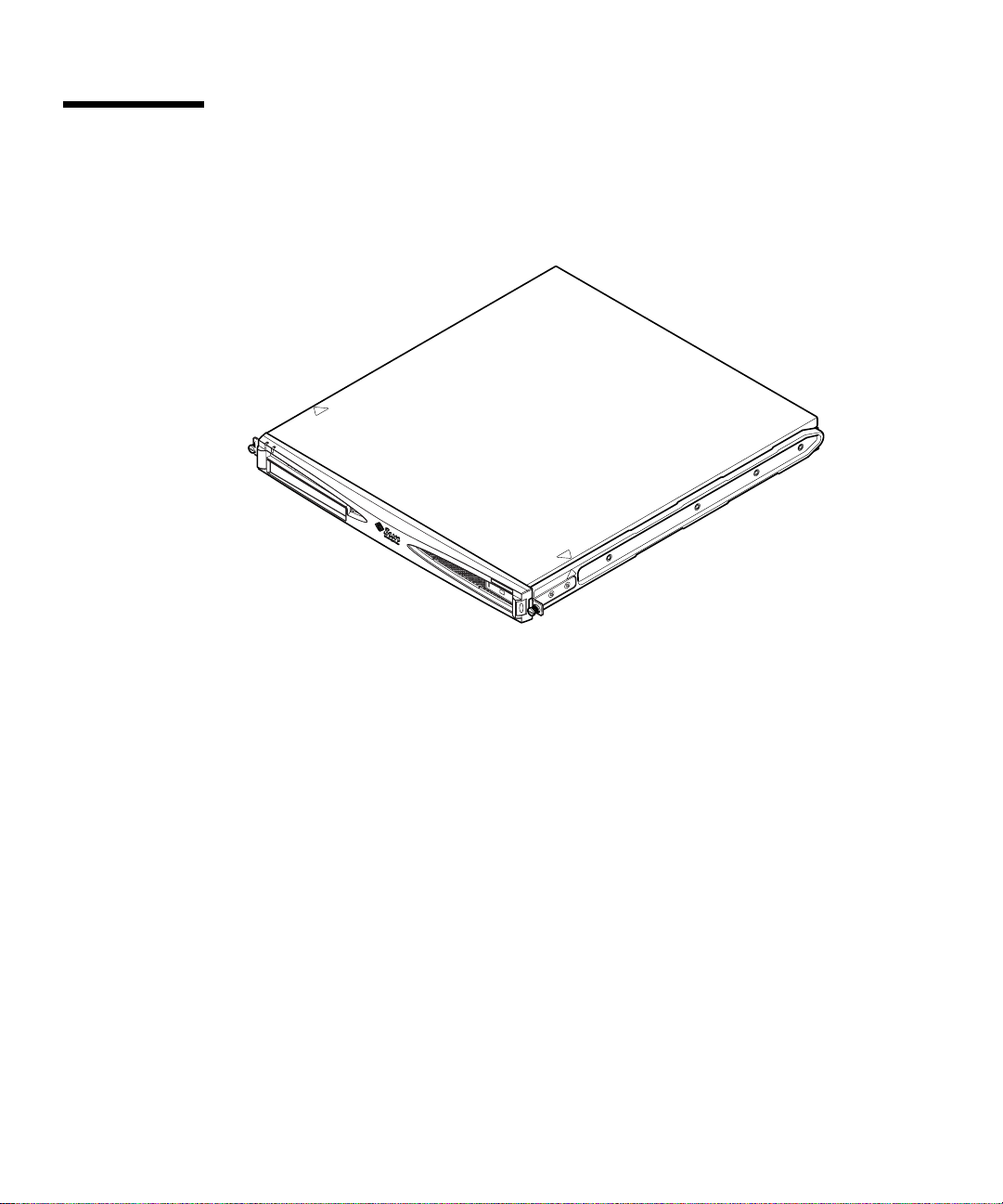
1.1 Overviewof the Sun FireV120 and Netra 120 Servers
FIGURE 1-1 The Sun Fire V120 Server
The Sun FireTMV120 and NetraTM120 servers are single-processor, thin (1U) servers
designed primarily for use by telecommunications carriers and internet service
providers. They are also suitable for use within corporate customer networks,
wherever there is a need to maximize the density of high-performance Solaris
servers.
The Sun Fire V120 and Netra 120 servers are identical except that the Sun Fire V120
is powered by an AC supply and the Netra 120 by –48VDC/–60VDC supplies. This
is the only difference between the two models.
The servers both have the following features:
■ Rackmounting enclosure with single power supply
■ UltraSPARC
■ Four DIMM sockets accepting 256 MB or 512 MB PC133 memory modules (giving
TM
IIe+ 550 or 650 MHz processor
a maximum of 2 GB of memory)
■ One 33-MHz, 32-bit, 5V PCI card slot
■ Two 10/100 Mbps RJ-45 Ethernet ports
■ Console/Lights-Out Management (LOM) RJ-45 serial port
1-2 Sun Fire V120 and Netra 120 Server User’s Guide • December 2001
Page 27

■ Second RJ-45 serial port
■ Optional DVD or CD-ROM drive
■ Support for up to two low-profile, 3.5-inch Fast-40 (Ultra2SCSI) disks
■ Support for up to two USB connections
■ External Fast-40 (Ultra2SCSI) Multimode 68-pin port
These servers are designed to be rackmounted. Their components are housed in a
casing with the following dimensions:
■ Height: 1.72 inches (43.6 mm)
■ Width: 17.2 inches (436.7 mm)
■ Depth: 18.8 inches (478 mm)
■ Weight (when all option modules are installed): 10 kg (22 lb)
1.2 Contents of the Ship Kit
TABLE1-1 Contents of the Ship Kit
Item Quantity Part Number
19-inch rackmounting brackets 4 340-5819-02
Cable management bracket 1 340-6151-01
Sun slide rail 2 540-4362-01
RJ-45 to RJ-45 patch cable for Ethernet or serial connection 2 530-2093-01
RJ-45 to DB-25 adapter 1 530-2889-02
DC connector kit (for Netra 120 systems only) 1 565-1644-01
10-32 UNF Sun rackmounting screw kit 1 565-1645-01
Side-mounting bracket screw kit 1 565-1654-01
Sun Fire V120 and Netra 120 Server User’s Guide (this manual) 1 816-2090-10
Sun Fire V120 and Netra 120 Set Up Poster 1 816-2091-xx
Sun Fire V120, Netra 120, and Netra T1 Servers: Safety and
Compliance Guide
Sun Fire V120 and Netra 120 Server Product Notes 1 816-2093-xx
1 806-6135-xx
Chapter 1 Introduction 1-3
Page 28
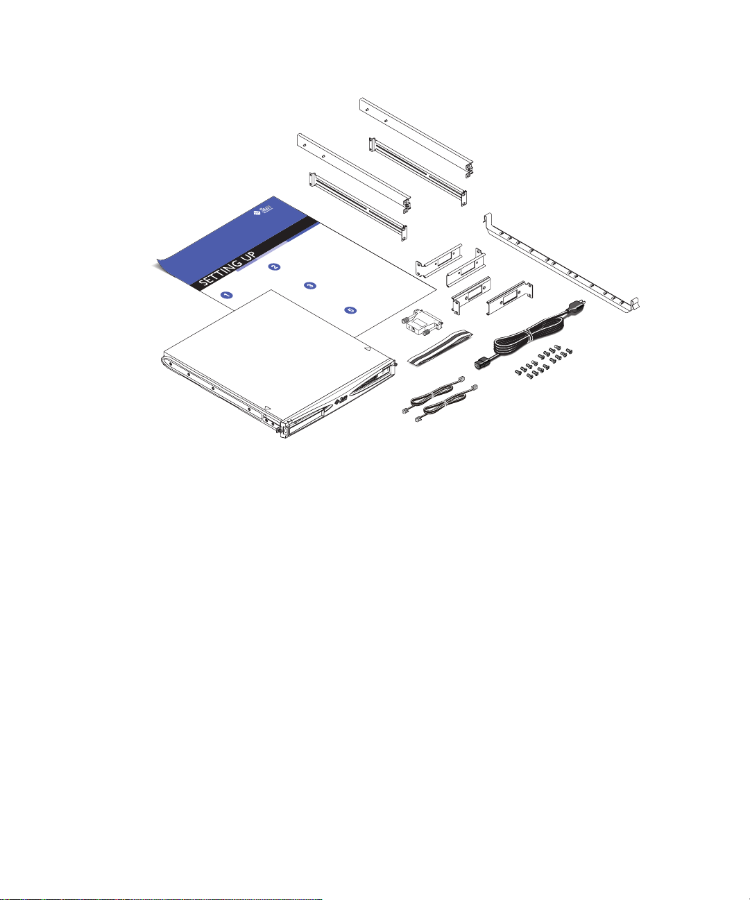
FIGURE 1-2 Contents of the Ship Kit
1-4 Sun Fire V120 and Netra 120 Server User’s Guide • December 2001
Page 29

1.3 Optional Hardware and Software
TABLE 1-2 lists the customer-installable hardware components and software packages
that are available for the Sun Fire V120 and Netra 120 servers. To order any of these
options, contact your local Sun sales representative.
TABLE1-2 Customer-Installable Hardware and Software
Optional Components Part Number
19-inch rackmount kit X7085A
23-inch rackmount kit X6966A
24-inch rackmount kit X6967A
600-mm rackmount kit X6968A
Internal CD-ROM drive X7088A
Internal DVD-ROM drive X1288A
18 GB hard disk X5239A
36 GB hard disk X5244A
256 MB DIMM X7091A
512 MB DIMM X7092A
Power splitter cable X7098A
5-pack serial port adapter X6973A
Gigabit Ethernet PCI Adapter 2.0 X1141A
FastEthernet 10/100Base-T F/W UltraSCSI PCI Adapter 1.0 X1032A
FastEthernet 10/100Base-T PCI Adapter 2.0 X1033A
Quad FastEthernet PCI Adapter (QFE) X1034A
High-Speed Serial Interface PCI Adapter 2.0 X1155A
ATM PCI Adapter 4.0 (155-Mbps Multi-Mode Fiber Interface) X1157A
ATM PCI Adapter 4.0 (155-Mbps UTP Interface) X1158A
Dual-Channel UltraSCSI Differential PCI Host Adapter X6541A
Serial Asynchronous Interface PCI Adapter X2156A
Crypto Accelerator PCI Adapter X1133A
Single-Loop FC-AL PCI Host Adapter X6729A
Gigabit Ethernet and FC-AL PCI Adapter X2069A
Chapter 1 Introduction 1-5
Page 30
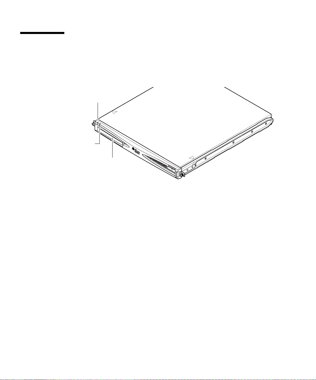
1.4 Front Panel
The illustration below shows the location of the Power and Fault LEDs, and the
DVD-ROM drive bay.
Power LED
Fault LED
DVD-ROM drivebay
FIGURE 1-3 The Front Panel of the Sun Fire V120 and Netra 120 Servers
1-6 Sun Fire V120 and Netra 120 Server User’s Guide • December 2001
Page 31

1.5 Back Panel
FIGURE 1-4 shows the components on the Sun Fire V120 server ’s back panel.
Power (On/Standby) switch
AC power inlet
Grounding studs Serial B port
FIGURE 1-4 The Back Panel of the Sun Fire V120 Server
FIGURE 1-5 shows the components on the Netra 120 server’s back panel. Except for
Serial A/LOM port Ethernet ports
Link 0
Link 1
USB ports
Optional PCI card
SCSI port
Fault
Power
the power inlets, they are identical to the components on the back panel of the Sun
Fire V120.
Power (On/Standby) switch
DC power inlet
Serial A/LOM port Ethernet ports
Optional PCI card
Grounding studs Serial B port
FIGURE 1-5 The Back Panel of the Netra 120 Server
Link 0
Link 1
USB ports
SCSI Port
Chapter 1 Introduction 1-7
Fault
Power
Page 32

1.6 The Fans Inside the Sun Fire V120 and Netra 120 Servers
The Sun Fire V120 and Netra 120 servers contain four fans. These are monitored by
the LOM device, so you can use the Lights-Out Management (LOM) commands to
check their status. For more information, see Chapter 8 and Chapter 9.
For a diagram showing the position of the fans inside the server, see “Identifying
Server Components” on page 4-6.
1.7 Tools You Need for Installation
■ An 8-mm wrench (for assembling the rackmounting).
■ A small flat-head screwdriver (for levering the grilles when installing hard disks).
■ An ESD pad and an antistatic wrist strap and earthing point (to protect the
components of the system if you need to install any hardware options).
■ A No. 2 Phillips screwdriver.
■ For Netra 120 servers that are stacked on top of each other in a rack, you need to
use a right-angled two-hole lug. Use a UL/CSA-approved component, such as the
one supplied by Thomas & Betts (part number: 54204-UB). You will also need a
crimping tool, such as the Thomas & Betts crimping tool (part number: TBM 5-S).
1-8 Sun Fire V120 and Netra 120 Server User’s Guide • December 2001
Page 33

1.8 Environmental Specifications
This section gives storage, operating and environmental compliance information.
1.8.1 Tolerance of Environmental Conditions
You can operate and store the system safely in the following conditions:
■ Ambient temperature
■ Operating: 5˚C to 40˚C (temporary operation outside these limits is permitted
for a maximum of 96 hours within the range –5˚C to 55˚C)
■ Storage: –40˚C to 70˚C
■ Relative humidity
■ Operating: 5% to 85% (non-condensing)
■ Storage: 10% to 95% (non-condensing)
■ Altitude
■ Operating: –300m to +3000m
■ Storage: –300m to +12000m
■ Earthquake
The system conforms to the NEBS requirements for earthquake zone 4
1.8.2 Acoustic Noise Generated by the Server
The server generates less than 60dBA at a distance of 23.67 inches (600mm) and a
height of 59.17 inches (1500mm) while operating in an ambient temperature of 25˚C.
1.8.3 Environmental Compliance Information
■ NEBS environmental criteria
The system conforms to GR-63-CORE issue 1, October 1995
■ Electromagnetic compatibility
■ Immunity: The system conforms to GR-1089-CORE and EN50082-1
■ Emissions: The system conforms to GR-1089-CORE, EN55022 Class A and FCC
Class A
■ Safety
The system conforms to UL 1950 (3rd edition), EN60950, GR-1089-CORE
Chapter 1 Introduction 1-9
Page 34

1.9 Choosing Between a Rack and a Cabinet
You can install the Sun Fire V120 or Netra 120 server in either a rack or a cabinet.
Factors that might influence your decision include:
■ Security
If other people have access to the room in which your server is located, you can
increase security by locking the server in a cabinet.
■ Thermal issues
Cabinets often require additional fans, because the servers you install in them are
generating heat in an enclosed space. Two-post racks, however, might require no
special cooling systems.
■ Flooring
Two-post telco relay racks are designed so that cables can be run overhead.
Cabinets often require cables to be run under the floor.
What’s Next?
When you have read this chapter, go to Chapter 2 to find out how to estimate the
power and cooling requirements for your server.
1-10 Sun Fire V120 and Netra 120 Server User’s Guide • December 2001
Page 35

CHAPTER
2
Power and Cooling
This chapter contains information about the power consumption of the Sun Fire
V120 and Netra 120 servers. It also tells you how to estimate the amount of heat that
your cooling system must dissipate.
The chapter contains the following sections:
■ Section 2.1, “Operating Power Limits and Ranges” on page 2-2
■ Section 2.2, “Power Consumption” on page 2-3
■ Section 2.3, “Estimating Heat Dissipation” on page 2-4
Note – The power supply on the Sun Fire V120 server continues to regulate all
outputs for at least 20 milliseconds after AC power is removed. On the Netra 120
server, the power supply continues to regulate all outputs for at least 4.5
milliseconds after DC power is removed.
Note – Standby power is available whenever input power is connected.
2-1
Page 36

2.1 Operating Power Limits and Ranges
The table below gives operating and power information for the Sun Fire V120 and
Netra 120 servers.
TABLE2-1 Operating Power Limits and Ranges for Sun Fire V120 and Netra 120 Servers
Description Sun Fire V120 Ser ver (AC power) Netra 120 Server (DC power)
Maximum operating
current
Maximum in-rush
current (cold start)
Maximum in-rush
current (warm start)
Maximum in-rush
current (hot start)
Operating input
voltage range
Voltage frequency
range
Power factor 0.8 to 1.0 Not applicable
BTU rating 550 BTU 550 BTU
2A @ 90 VAC 4A @ –40 VDC
20A peak upon a restart
performed 60 seconds or more
after the removal of AC power
40A peak upon a restart
performed less than 60 seconds
but more than 200 milliseconds
after the removal of AC power
100A peak upon a restart
performed less than 200
milliseconds after the removal
of AC power
90-264 V
47-63 Hz DC
rms
20A peak upon a restart
performed 60 seconds or more
after the removal of DC power
40A peak upon a restart
performed less than 60 seconds
but more than 200 milliseconds
after the removal of DC power
100A peak upon a restart
performed less than 200
milliseconds after the removal
of DC power
–40 to –75 VDC
*
For both servers, the in-rush current decays to the normal operating current in less than
200 milliseconds. The in-rush decaying peaks last for less than 3 milliseconds in each half
cycle.
Note – The figures for the maximum operating current are provided to help you
specify the fusing and cabling you need to deliver power to your equipment.
However, these figures represent “worst-case” scenarios. Such occurrences are
unlikely in a real installation.
2-2 Sun Fire V120 and Netra 120 Server User’s Guide • December 2001
Page 37

2.2 Power Consumption
To estimate the total power consumption for several Sun Fire V120 or Netra 120
servers installed in a single rack or cabinet, add together the individual power
requirement figures for each of the systems that you have installed (see
TABLE2-2 Power Consumption for the Available Configurations of the Server
TABLE 2-2).
Server Model Hardware Options
Installed
Sun Fire V120 550MHz CPU
36 GB hard disk
512 MB DIMM
Sun Fire V120 650MHz CPU
2x36 GB hard disk
1 GB DIMM
Sun Fire V120 650MHz CPU
1x36 GB hard disk
512 MB DIMM
Netra 120 650MHz CPU
36 GB hard disk
512 MB DIMM
Power Consumption
(Nominal)
55 W 73 VA
74 W 100 VA
58 W 78 VA
58 W 70 W
Power Consumption
(Maximum)
Note – Adding optional hardware components to your system will increase its
power consumption. For a list of the optional hardware components available for
these servers, see Section 1.3, “Optional Hardware and Software” on page 1-5.
Chapter 2 Power and Cooling 2-3
Page 38

2.3 Estimating Heat Dissipation
To estimate the amount of heat generated by a Sun Fire V120 or Netra 120 server so
that you can estimate the heat your cooling system must dissipate (see Section 2.2,
“Power Consumption” on page 2-3), convert the figure for the server’s power
consumption from watts to BTU per hour.
A general formula for doing this is to multiply the figure for the power consumption
by 3.415. For example, the heat that must be dissipated for a Sun Fire V120 server
containing a 650 MHz processor, a single 36 GB hard disk drive, and a single 512 MB
DIMM is:
58 x 3.415 = 198.07 BTU/hr
You can install up to 32 Sun Fire V120 or Netra 120 servers into a Sun StorEdge 72-
inch rack. To estimate the heat your cooling system must dissipate, add together the
nominal power consumption for each server in the rack, then multiply the result by
3.415. For example, 30 servers each containing a 650 MHz processor, containing a
single 36 GB hard disk and a single 512 MB DIMM will generate the following
amount of heat:
(30 x 58 W) x 3.415 = 5942.10 BTU/hr
What’s Next?
When you have used this chapter to estimate the power and cooling requirements
for your server, go to Chapter 3, which tells you how to assemble the DC input
power cables for the Netra 120 server; or if you are installing a Sun Fire V120 server,
go straight to Chapter 4 to find out how to install the optional hardware components
available for both servers.
2-4 Sun Fire V120 and Netra 120 Server User’s Guide • December 2001
Page 39

CHAPTER
3
Using DC Power
This chapter applies only to the Netra 120 server. If you have purchased a
Sun Fire V120 server, skip this chapter and go to Chapter 4.
This chapter provides information on grounding a Netra 120 server and on
assembling the DC power connectors.
It contains the following sections:
■ Section 3.1, “Grounding the Netra 120 Server” on page 3-2
■ Section 3.2, “Assembling the DC Power Connectors” on page 3-3
3-1
Page 40

3.1 Grounding the Netra 120 Server
The two M5 grounding studs on the server’s back panel are the recommended safety
grounding point (see
provided by the middle pin of the WAGO connector.
M5 grounding
studs
FIGURE 3-1 The Location of the Grounding Studs for Connecting the Two-Hole Lug
● To ground the server, take a ground conductor and terminate it using a right-
angled two-hole lug.
Make sure that it is UL/CSA-approved, that it is suitable for an 8 AWG (6mm
conductor, and that it has a 5/8-inch pitch.
Note – For Netra 120 servers that are stacked on top of each other in a rack, you
need to use a right-angled two-hole lug. Use a UL/CSA-approved component, such
as the one supplied by Thomas & Betts (part number: 54204-UB).
FIGURE 3-1). However, an alternative grounding point is
2
)
● To secure the lug onto the ground conductor cable, use a UL/CSA-approved
crimping tool, such as the one supplied by Thomas & Betts (part number: TBM 5S).
Do not use a torque value of more than 3.5 Nm maximum.
Connect the free end of the ground conductor cable to an earthing bar located near
to the equipment.
Caution – External filtering and/or surge suppression devices may be required on
the power feeds where branch circuit electromagnetic characteristics are unknown.
Note – For more information about grounding the server, refer to the Sun Fire V120,
Netra 120, and Netra T1 Servers: Safety and Compliance Guide (part number: 816-3211).
3-2 Sun Fire V120 and Netra 120 Server User’s Guide • December 2001
Page 41

3.2 Assembling the DC Power Connectors
The Netra 120 server has a dedicated connector kit; this section explains how to use
it.
3.2.1 The Insulated Conductors You Need to Use
The insulated conductors you use must have the following characteristics:
■ Material: tinned copper (multistranded)
■ Size: 12 AWG (2.5 mm
■ Rating:
■ 300 vrms (minimum)
O
■ 75
C
■ Low-smoke fume (LSF)
■ Fire resistance:
■ VW-1
■ GR63-CORE compliant
You need two supply conductors:
■ One -48V (or -60V) DC supply conductor (return, RTN) grounded at source
■ One DC supply conductor (- minus)
Finally, you need one power supply unit (PSU) ground conductor.
2
) (maximum)
3.2.2 Assembling the DC Input Power Cable
1. Determine how many DC input power cables you will need from each DC power
source.
2. Turn off power to the DC power source through the circuit breakers.
Caution – Do not proceed with these instructions until you have turned off the
power to the DC power source through the circuit breakers.
3. Take a DC connector from the ship kit.
4. Locate the Supply and Return wires (and the PSU Ground, if you are using it)
coming from the DC power source that you intend to use in the connection to your
server:
Chapter 3 Using DC Power 3-3
Page 42

■ –48V Supply
■ PSU Ground
■ –48V Return
5. Strip 0.31 inches (8 mm) of insulation from each of the wires coming from the DC
power source (see
FIGURE 3-2).
Do not strip more than 0.31 inches (8 mm) from each wire. Doing so will leave
uninsulated wire exposed from the DC connector after the assembly is complete.
0.31 in. (8 mm)
FIGURE 3-2 Stripping the Insulation From the Wire
3-4 Sun Fire V120 and Netra 120 Server User’s Guide • December 2001
Page 43

6. Insert the tip of the cage clamp operating lever into the rectangular hole directly
above the hole in the DC connector where you want to insert the first wire.
Then press down on the cage clamp operating lever (see
FIGURE 3-3). This opens the
cage clamp for this section of the DC connector.
You can also open the DC connector cage clamp by inserting a small slotted
screwdriver into the rectangular hole directly above the hole in the DC connector
where you want to insert the first wire, and then pressing down on the screwdriver
(see
FIGURE 3-4).
FIGURE 3-3 Opening the DC Connector Cage Clamp (Lever Method)
Chapter 3 Using DC Power 3-5
Page 44

Top of connector
FIGURE 3-4 Opening the DC Connector Cage Clamp (Screwdriver Method)
7. Feed the exposed section of the appropriate wire into that hole in the DC
connector.
FIGURE 3-5 shows which wires should be inserted into each hole in the DC connector.
Top of connector
–48V Return
Ground
123
FIGURE 3-5 Assembling the DC Input Power Cable
8. Repeat Step 6 and Step 7 for the other two wires to complete the assembly of the
DC input power cable.
9. Repeat Step 4 through Step 8 to create a second DC input power cable.
If you need to remove a wire from the DC connector, insert the cage clamp operating
lever or a small screwdriver into the slot directly above the wire and press down
(
FIGURE 3-3 and FIGURE 3-4).
3-6 Sun Fire V120 and Netra 120 Server User’s Guide • December 2001
–48V
Page 45

3.2.3 Installing the Strain Relief Housings
1. Insert the bottom portion of the strain relief housing into the notch on the DC
connector until it snaps into place (see
Make sure that the strain relief housing snaps into place on the DC connector,
otherwise you will not be able to complete the assembly correctly.
FIGURE 3-6).
FIGURE 3-6 Inserting the Bottom Portion of the Strain Relief Housing
2. Route the three wires coming from the DC power source through the opening at
the end of the bottom portion of the strain relief housing (see
Chapter 3 Using DC Power 3-7
FIGURE 3-7).
Page 46

FIGURE 3-7 Routing the Wires Out of the Strain Relief Housing
3. Insert the tie wrap into the bottom portion of the strain relief housing (see
FIGURE 3-8).
FIGURE 3-8 Securing the Wires to the Strain Relief Housing
4. Loop the tie wrap over the wires and back out of the strain relief housing and
tighten the tie wrap to secure the wires to the strain relief housing (see
5. Position the top portion of the strain relief housing so that the three prongs on the
top portion fit into the openings in the DC connector, and push them together
until they snap into place (see
3-8 Sun Fire V120 and Netra 120 Server User’s Guide • December 2001
FIGURE 3-9).
FIGURE 3-8).
Page 47

FIGURE 3-9 Assembling the Strain Relief Housing
What’s Next?
The DC input power cables for your server are now completely assembled. For
information about connecting the power cords and other cables, see Chapter 6. Do
not power on the server (see Chapter 7) until you have installed any optional
hardware components you need (see Chapter 4) and until you have installed the
server securely into a rack or cabinet (see Chapter 5).
Chapter 3 Using DC Power 3-9
Page 48

3-10 Sun Fire V120 and Netra 120 Server User’s Guide • December 2001
Page 49

CHAPTER
4
Installing Optional Hardware Components
If you do not want to install any optional hardware components, skip this chapter
and go straight to Chapter 5, which tells you how to install the Sun Fire V120 and
Netra 120 servers into a rack.
This chapter tells you how to install or remove the hot-pluggable Hard Disk Drives.
To do this, you do not need to power off the server or remove it from the rack. This
chapter also tells you how to remove the cover of the server, how to identify the
parts of the server, how to install a DVD or CD-ROM drive, and how to install
DIMMs and a PCI card.
For the part numbers of the hardware components available from your local Sun
sales representative, see Section 1.3, “Optional Hardware and Software” on page 1-5.
This chapter contains the following sections:
■ Section 4.1, “Installing and Removing Hot-Pluggable SCSI Hard Disk Drives” on
page 4-2
■ Section 4.2, “Opening the Server” on page 4-4
■ Section 4.3, “Identifying Server Components” on page 4-6
■ Section 4.4, “Installing and Removing a DVD or CD-ROM Drive” on page 4-7
■ Section 4.5, “Installing and Removing Memory” on page 4-9
■ Section 4.6, “Installing and Removing a PCI Card” on page 4-11
■ Section 4.7, “Replacing the Server’s Top Cover” on page 4-14
4-1
Page 50

4.1 Installing and Removing Hot-Pluggable SCSI Hard Disk Drives
Note – The server and Hard Disk Drives contain electronic parts that are extremely
sensitive to static electricity. Do not touch any metal parts. Wear an antistatic wrist
strap.
The Hard Disk Drives are hot-pluggable modules. This means that you do not need
to power off the server or remove it from the rack to install or remove the Hard Disk
Drives.
However, you do need to make sure that no system or application software is using
a Hard Disk Drive when you remove it.
Note – If you intend to remove a Hard Disk Drive with Solaris running, follow the
instructions in Appendix A before performing the steps below.
1. Remove the front bezel.
Release the bezel from the server by pressing in on the tabs at either end of the bezel.
2. Pull out the grilles.
3. Do one of the following:
■ If you are installing a Hard Disk Drive, slide it into its tray at the front of the
server (see
indicates that it has engaged with the backplane connector. Then, push the metal
lever until the disk drive clicks into place.
FIGURE 4-1). Push it in firmly until the metal lever starts to close: this
Note – When inserting a Hard Disk Drive into its enclosure, make sure the top of
the drive is touching the top of the enclosure. If you try to install it with the bottom
of the drive touching the bottom of the enclosure, the drive will not align with the
slide rails inside the enclosure, and you will not be able to insert the disk.
■ If you are removing a Hard Disk Drive, locate the latch at the front of the disk and
slide it to the right (see
the latch, pull the disk part way out of its bay and leave it for a minute to make
sure it has stopped spinning. (If a disk is fully removed while it is still spinning,
gyroscopic forces can damage its bearings.) When it has stopped spinning, pull it
out of the chassis.
4-2 Sun Fire V120 and Netra 120 Server User’s Guide • December 2001
FIGURE 4-1). This causes the metal lever to open. Holding
Page 51

4. Replace the grilles and front bezel.
5. If you have just installed a Hard Disk Drive and you have Solaris running, you
must now perform the steps in Section A.1, “Installing a SCSI Hard Disk Drive
With Solaris Running” on page A-2.
FIGURE 4-1 Inserting and Removing Hard Disks
Chapter 4 Installing Optional Hardware Components 4-3
Page 52

4.2 Opening the Server
Caution – The server contains electronic parts that are extremely sensitive to static
electricity. Do not touch any metal parts. Place the server on top of a grounded
electrostatic discharge (ESD) pad. Attach the disposable antistatic wrist strap
supplied with the server to its metal base before touching any of the internal
components.
Caution – Before attempting to remove the cover, make sure that all power cords
and all other cables have been disconnected from the server.
ESD pad
FIGURE 4-2 Using the Antistatic Wrist Strap Supplied With the Server
4-4 Sun Fire V120 and Netra 120 Server User’s Guide • December 2001
Page 53

1. If your server is new and you have just removed it from its packaging, go straight
to Step 3.
If your server is currently in use, but you need to open it to install or replace a
hardware component, then:
a. Shut down and power off the server.
b. Disconnect the power cord(s).
c. Disconnect all other cables.
2. If you have installed the server into a rack or cabinet, remove it from the rack or
cabinet.
3. Place the server on a grounded ESD surface and use an antistatic wrist strap.
4. Remove the server’s top cover (see
FIGURE 4-3):
a. Undo the captive screw at the rear center of the unit (see
b. Slide the top cover back and lift it off (see
Step 4b
FIGURE 4-3).
Step 4a
FIGURE 4-3).
FIGURE 4-3 Removing the Top Cover
Chapter 4 Installing Optional Hardware Components 4-5
Page 54

4.3 Identifying Server Components
The major components of the Sun Fire V120 and Netra 120 servers, and the location
of each component, are shown below, in
1. PCI card (optional)
2. System configuration card reader
3. Top cover
FIGURE 4-4:
4. Hard Disk Drive
5. Optional DVD or CD-ROM drive
6. Filler panel
7. Front bezel
8. Grills
9. Fan 3 ducting
10. DIMM
2
11. Power Supply Unit
12. Fans 1 and 2
13. Fan 3 (CPU)
14. Fan 4
5
6
7
3
9
4
8
1
10
11
14
13
12
FIGURE 4-4 Components of the Sun Fire V120 and Netra 120 Servers
4-6 Sun Fire V120 and Netra 120 Server User’s Guide • December 2001
Page 55

4.4 Installing and Removing a DVD or CD-ROM Drive
Class 1 Laser Product
Luokan 1 Laserlaite
Klasse 1 Laser Apparat
Laser Klasse 1
Caution – Follow the instructions in this section carefully. The DVD or CD-ROM
drive contains a laser device. Do not attempt to open the DVD or CD-ROM drive’s
enclosure or remove a DVD or CD-ROM drive using any procedures other than
those contained in this section. If you do, you risk exposure to radiation.
4.4.1 Installing a DVD or CD-ROM Drive
Note – If you are going to install a full-length PCI card, install the DVD or
CD-ROM drive first. If you have a full-length PCI card already installed, you need to
!
remove it before installing the DVD or CD-ROM drive.
1. Remove the top cover by following the procedure described in Section 4.2,
“Opening the Server” on page 4-4.
Make sure you disconnect all power cables and wear an antistatic wrist strap.
2. Remove the front bezel.
Release it from the server by pressing in on the tabs at either end of the bezel.
3. If you have a full-length PCI card installed, you must remove it before installing
the DVD or CD-ROM drive (see Section 4.6.2, “Removing a PCI Card” on
page 4-14).
4. Squeeze and pull out the filler panel at the front of the DVD or CD-ROM
enclosure.
Chapter 4 Installing Optional Hardware Components 4-7
Page 56

5. Carefully insert the DVD or CD-ROM drive into the chassis (see FIGURE 4-5).
Make sure that the catch at the rear of the DVD or CD-ROM drive clicks onto the
chassis. Guide the drive in so that its connectors align with, and then engage with,
the connectors on the paddleboard (see
FIGURE 4-5) at the back of the drive’s
enclosure in the chassis. You may need to hold the paddleboard by the black IDE
connector to guide the DVD or CD-ROM drive home.
6. Re-install the full-length PCI card if you removed one (see Section 4.6, “Installing
and Removing a PCI Card” on page 4-11).
7. Replace the server’s cover and tighten the captive screw (see
Section 4.7, “Replacing the Server ’s Top Cover” on page 4-14).
8. Replace the front bezel.
Paddleboard
Catch
FIGURE 4-5 Installing an Internal DVD or CD-ROM Drive
FIGURE 4-9 in
4-8 Sun Fire V120 and Netra 120 Server User’s Guide • December 2001
Page 57

4.4.2 Removing a DVD or CD-ROM Drive
1. Remove the top cover by following the procedure described in Section 4.2,
“Opening the Server” on page 4-4.
Make sure you disconnect all power cables and wear an antistatic wrist strap.
2. Remove the front bezel.
Release it from the server by pressing in on the tabs at either end of the bezel.
3. Unclip the catch that fastens the DVD or CD-ROM drive to the chassis.
This catch is located at the back right-hand corner of the drive’s casing.
4. Carefully but firmly pull the DVD or CD-ROM drive out of its connector at the
rear of the enclosure and pull the drive out of the chassis.
5. Replace the server cover and tighten the captive screw (see
Section 4.7, “Replacing the Server ’s Top Cover” on page 4-14).
6. Replace the front bezel.
FIGURE 4-9 in
4.5 Installing and Removing Memory
There are four memory module sockets on the server’s system board. You can install
a 256 or 512 MB DIMM into each socket. For the maximum 2 Gbytes of memory,
install four 512 MB DIMMs. For the sales part numbers of the DIMMs available from
your local Sun sales representative, see Chapter 1.
1. Remove the top cover by following the procedure described in Section 4.2,
“Opening the Server” on page 4-4.
Make sure you wear an antistatic wrist strap and that you disconnect all power
cables.
2. Insert the memory module into a vacant DIMM socket, or, if you are removing
memory, open the latches at the sides of the socket and remove the module.
Chapter 4 Installing Optional Hardware Components 4-9
Page 58

3. Replace the server’s cover and tighten the captive screw (see FIGURE 4-9 in
Section 4.7, “Replacing the Server ’s Top Cover” on page 4-14).
FIGURE 4-6 Installing Memory into a Socket on the System Board
Note – There are four DIMM slots. The one nearest to the CPU fan is slot 0. The one
nearest to the power supply unit is slot 3. Put the first DIMM in slot 0, and install
subsequent DIMMs in contiguous slots.
4-10 Sun Fire V120 and Netra 120 Server User’s Guide • December 2001
Page 59

4.6 Installing and Removing a PCI Card
For a list of the PCI cards available from your local Sun Sales representative, see
“Optional Hardware and Software” on page 1-5.
4.6.1 Installing a PCI Card
Note – If you are installing a full-length PCI card and you also want to install a
DVD-ROM drive, install the DVD-ROM drive first (see Section 4.4, “Installing and
Removing a DVD or CD-ROM Drive” on page 4-7). Otherwise, when you install the
DVD-ROM drive, you will have to remove the PCI card that you have installed.
To install a PCI card into the server, do the following:
1. Remove the top cover by following the procedure described in “Opening the
Server” on page 4-4.
Make sure you wear an antistatic wrist strap and disconnect all power cables.
2. Remove the filler panel protecting the PCI connector.
3. Loosen the captive screw holding the PCI slot’s retention bracket in place (see
FIGURE 4-7).
Rotate the retention bracket through 90 degrees (see
filler panel in the PCI slot, enabling you to remove the filler panel. Remove it.
FIGURE 4-7). This releases the
4. If you are installing a full-length PCI card, slide the PCI card retainer off the PCI
slide support rail on the system board.
5. Insert the PCI card firmly into the PCI connector (see
the PCI card’s bracket is correctly positioned against the rear of the chassis.
The tapered end of the bracket must be inside the small metal tab designed for it on
the chassis (see
FIGURE 4-7).
Chapter 4 Installing Optional Hardware Components 4-11
FIGURE 4-7) making sure that
Page 60

Metal
PCI connector
FIGURE 4-7 The Rotating Retention Bracket and the Position of a PCI Card
tab
4-12 Sun Fire V120 and Netra 120 Server User’s Guide • December 2001
Page 61

6. Slide the PCI card retainer into a position at the back of the PCI card to prevent
excessive flexing of the board (see
FIGURE 4-8).
If you are installing a full-length PCI card, insert the back end of the card into the
groove in the plastic bracket shown in
FIGURE 4-8; this provides extra support.
Plastic bracket
FIGURE 4-8 Using the PCI Card Retainer, Slide Support Rail, and Plastic Bracket
7. Reposition and tighten the rotating retention bracket (see FIGURE 4-7) to secure the
PCI card to the chassis.
8. Replace the server’s cover and tighten the captive screw (see
FIGURE 4-9 in
Section 4.7, “Replacing the Server ’s Top Cover” on page 4-14).
Chapter 4 Installing Optional Hardware Components 4-13
Page 62

4.6.2 Removing a PCI Card
1. Remove the top cover by following the procedure described in “Opening the
Server” on page 4-4.
Make sure you wear an antistatic wrist strap and that you disconnect all power
cables.
2. Loosen the captive screw that secures the rotating retention bracket (the screw and
bracket are illustrated in
Rotate the retention bracket through 90 degrees (see
3. Move the PCI card retainer along the PCI slide support rail until it is no longer
touching the PCI card (see
4. Remove the PCI card from the PCI connector.
5. Replace the filler panel that protects the pins in the PCI connector.
6. Replace the filler panel for the PCI slot (in the back panel of the chassis), and
tighten the captive screw that secures the rotating retention bracket (see
FIGURE 4-7).
FIGURE 4-7).
FIGURE 4-8).
FIGURE 4-7).
7. Replace the server cover and tighten the captive screw (see
Section 4.7, “Replacing the Server ’s Top Cover” on page 4-14).
FIGURE 4-9 in
4.7 Replacing the Server’s Top Cover
When you have finished installing an option module, replace the server’s top cover.
1. Lower the lid onto the server with the indented arrows on the lid and side of the
server lining up.
2. Slide the lid home towards the front of the server.
3. Tighten the captive retaining screw at the rear (see
FIGURE 4-9).
4-14 Sun Fire V120 and Netra 120 Server User’s Guide • December 2001
Page 63

Alignment arrows
FIGURE 4-9 Replacing the Top Cover
What’s Next?
When you have installed the optional hardware components you need, go to
Chapter 5 for information about installing the Sun Fire V120 and Netra 120 servers
into a rack.
Chapter 4 Installing Optional Hardware Components 4-15
Page 64

4-16 Sun Fire V120 and Netra 120 Server User’s Guide • December 2001
Page 65

CHAPTER
5
Installing the Server Into a Rack
This chapter tells you how to install a Sun Fire V120 or Netra 120 server into a rack.
The chapter contains the following sections:
■ Section 5.1, “Installing Into a 19-Inch Four-Post Rack” on page 5-2
■ Section 5.2, “Installing Into a Two-Post Relay Rack” on page 5-12
5-1
Page 66

5.1 Installing Into a 19-Inch Four-Post Rack
5.1.1 The 19-Inch Rackmounting Kit
The mounting slides can each be used on either side of the rack. The parts required
are listed in
Section 1.3, “Optional Hardware and Software” on page 1-5).
TABLE5-1 19-inch Rackmounting Kit
Item Quantity Part No.
Front slide 2 340-6125
Rear slide 2 340-6234
Cable management bracket 1 340-6151
M4 nuts 4 240-1373
Rack screw kit 1 565-1645
A bracket is provided to aid cable management at the back of the server (see
FIGURE 5-1).
TABLE 5-1. The part number of the rackmounting kit is X6919A (see
FIGURE 5-1 Cable Management Bracket
5-2 Sun Fire V120 and Netra 120 Server User’s Guide • December 2001
Page 67

5.1.2 Assembling the Slides and Mounting the Server
1. Position the two parts of the slide so that the double-angled ear (A) is in the
correct position for the rack you are installing into.
■ For the Sun 72-inch tall (19-inch wide) rack, the double-angled ear (A) must be to
the rear (see
■ For a standard 19-inch wide rack, the double-angled ear (A) must be to the front
(see
FIGURE 5-3).
FIGURE 5-2 Positioning the Slide Mounts for a Sun StorEdge 72-Inch Tall Rack
FIGURE 5-2).
A
A
FIGURE 5-3 Positioning the Slide Mounts for a Standard 19-Inch Wide Rack
Chapter 5 Installing the Server Into a Rack 5-3
Page 68

2. Loosely screw the two parts of the slide mounts together, using the M4 nuts
supplied.
3. Measure the distance between the front and back posts of your rack.
4. Adjust the slide mounts so that the distance between the front and back mounting
ears is approximately the distance between the front and back posts of the rack.
5. Move the brackets so that the studs are in suitable slots, and tighten the nuts.
6. Fasten the mounting slides to the rack, using the screws supplied.
For the Sun StorEdge 72-inch rack, refer to
FIGURE 5-4 and FIGURE 5-5. Leave the
screws slightly loose to allow adjustment when you slide the server into the rack.
For a standard 19-inch rack, refer to
FIGURE 5-6. Leave the screws slightly loose to
allow adjustment when you slide the server into the rack.
5-4 Sun Fire V120 and Netra 120 Server User’s Guide • December 2001
Page 69

FIGURE 5-4 Fastening the Slide Mounts to a Sun StorEdge 72-inch Tall Rack–Rear View
(Side Panels Removed for Clarity)
Chapter 5 Installing the Server Into a Rack 5-5
Page 70

FIGURE 5-5 Fastening the Slide Mounts to a Sun StorEdge 72-inch Expansion Rack–Front
View (Side Panels Removed for Clarity)
5-6 Sun Fire V120 and Netra 120 Server User’s Guide • December 2001
Page 71

FIGURE 5-6 Fastening the Slide Mounts to a Standard 19-inch Rack
7. Slide the server into the rack (see FIGURE 5-7).
Chapter 5 Installing the Server Into a Rack 5-7
Page 72

FIGURE 5-7 Sliding the Server Into a Standard 19-Inch Rack
5-8 Sun Fire V120 and Netra 120 Server User’s Guide • December 2001
Page 73

8. Align the server so that the thumbscrews on its sides fit into the slide mounts in
the rack (see
FIGURE 5-8).
If necessary, readjust the slide mounts so that the server aligns correctly. This job is
easier with the thumbscrews done up finger-tight.
FIGURE 5-8 Adjusting the Slide Mounts and Screwing the Server Into the Rack
9. Tighten the slide mounts in the rack.
10. Use a screwdriver to tighten the thumbscrews on the side of the server.
The server is now securely installed in the rack.
Chapter 5 Installing the Server Into a Rack 5-9
Page 74

5.1.3 Fitting the Cable Management Bracket
● Hook the bracket over the slide mounts at the rear of the server (see FIGURE 5-9).
You can use the loops in the bracket to secure the cables with cable ties.
Cable management bracket
FIGURE 5-9 Fitting the Cable Management Bracket to a Sun StorEdge or a Standard 19-
5-10 Sun Fire V120 and Netra 120 Server User’s Guide • December 2001
Inch Rack
Page 75

5.1.4 Tips for Using a Sun StorEdge 72-inch Rack
■ For maximum stability, fill the rack from the bottom up and leave at least 4U of
space free at the top.
■ To prevent warm air flowing to the front of the rack and being recirculated (which
would reduce the efficiency of your cooling system and potentially cause
overheating), close off the empty spaces at the top of the rack with filler panels.
The following filler panels are available from your local Sun sales representative:
■ 1U (part number: 330-2610-01)
■ 2U (part number: 330-2611-01)
■ 3U (part number: 330-2613-01)
■ 4U (part number: 330-2614-01)
■ 5U (part number: 330-2615-01)
■ Position your racks so that the warm air exhaust from one rack does not flow
directly into the cool air intake area for another.
■ If space is limited at the back of your Sun StorEdge 72-inch rack, install a
redundant fan tray (part number: X9819A) into the top of the rack. This pulls air
up through the top of the rack to prevent the build-up of heat behind it.
What’s Next?
When you have installed your server into the rack, go to Chapter 6 for information
about connecting the cables and setting up serial connections.
Chapter 5 Installing the Server Into a Rack 5-11
Page 76

5.2 Installing Into a Two-Post Relay Rack
5.2.1 The Fixed Mounting Bracket Kit
The parts you require are listed in TABLE 5-2.
TABLE5-2 Fixed Mounting Bracket Kit
Item Quantity Part No.
Brackets 4 340-5819
M4 x 8-mm countersunk Phillips screw kit 1 565-1654
5.2.2 Attaching the Fixed-Mounting Brackets
1. Remove the thumbscrew rackmounting brackets from either side of the server (see
FIGURE 5-10).
FIGURE 5-10 Removing the Thumbscrew Brackets
5-12 Sun Fire V120 and Netra 120 Server User’s Guide • December 2001
Page 77

2. Remove the first, third, and fourth screws from the plastic slide-mounts on the
sides of the server (see
FIGURE 5-11).
3. Fit the front brackets to the second and third of the tapped holes along the side of
the server (counting from the front of the server towards the rear).
Use the Phillips-head countersunk screws provided. See
FIGURE 5-11, but do not fit
the rear brackets yet.
Note – Only fit the rear brackets when you have completed steps 1 through 4.
FIGURE 5-11 Fitting the Fixed Mounting Brackets
4. Secure the server to the rack using the front brackets only, but do not fully tighten
the screws yet.
5. Fit the two rear fixed brackets to the two tapped holes at the rear of the server on
each side, using the Phillips-head countersunk screws provided (see
FIGURE 5-12).
6. Align the screws and tighten them.
Chapter 5 Installing the Server Into a Rack 5-13
Page 78

FIGURE 5-12 The Server Installed in a Two-Post Rack
What’s Next?
When you have installed the server into the rack, go to Chapter 6 for information
about connecting the cables and setting up serial connections.
5-14 Sun Fire V120 and Netra 120 Server User’s Guide • December 2001
Page 79

CHAPTER
6
Connecting the Cables
This chapter describes how to connect the power cables and the Ethernet and serial
cables to the Sun Fire V120 and Netra 120 servers. It also tells you how to set up the
serial connections you need.
Make sure you have installed the server into a rack or cabinet (see Chapter 5) before
following the instructions in this chapter.
This chapter contains the following sections:
■ Section 6.1, “Connecting the Cables to the Server” on page 6-2
■ Section 6.2, “Using a Single DC Power Cord” on page 6-4
■ Section 6.3, “Setting Up Serial Connections” on page 6-4
■ Section 6.4, “Connecting to Your Server From a Laptop Running Microsoft
Windows” on page 6-10
6-1
Page 80

6.1 Connecting the Cables to the Server
Serial
AC power
cable
DB-25 adapter
DB-25 adapter
FIGURE 6-1 Connecting the Cables to the Sun Fire V120 Server
DCpower
cable
links
Ethernet
links
Serial
links
Ethernet
links
SCSI adapter
SCSI adapter
DB-25 adapter
FIGURE 6-2 Connecting the Cables to the Netra 120 Server
6-2 Sun Fire V120 and Netra 120 Server User’s Guide • December 2001
Page 81

Before following the instructions in this section, make sure you have installed the
server into a rack or cabinet (see Chapter 5).
1. Connect the power cord or cords.
2. Connect the server to at least one Ethernet hub.
You can connect to a maximum of two Ethernet hubs (unless you have a PCI adapter
installed).
3. Connect a serial device to the Serial A/LOM port.
To use the server’s remote monitoring and management facilities, you must use the
port labeled Serial A/LOM. For more information about remote monitoring and
management, see Chapter 8 and Chapter 9.
If you intend to configure the server directly from a dumb terminal or a Sun
workstation, insert the loose end of the serial cable into the DB-25 adapter supplied
(see
FIGURE 6-1 and FIGURE 6-2). Then plug the adapter into the DB-25 serial
connector on the terminal or Sun workstation you intend to use.
For more information, see Section 6.3, “Setting Up Serial Connections” on page 6-4.
4. If you need to connect the server to an external SCSI device, you will need to use
the SCSI cable supplied with that device.
The server’s external SCSI bus is compatible with SCSI devices of the following
types:
■ Single Ended (SE)
■ Low Voltage Differential (LVD)
■ Narrow (8-bit)
■ Wide (16-bit)
Caution – AC-powered Sun products are designed to work with single-phase
power systems that have a grounded neutral conductor. To reduce the risk of electric
shock, do not plug Sun products into any other type of power system. Contact your
facilities manager or a qualified electrician if you are not sure what type of power is
supplied to your building.
Caution – Your AC-powered Sun product is shipped with a grounding type (three-
wire) power cord. To reduce the risk of electric shock, always plug the cord into a
grounded outlet.
Chapter 6 Connecting the Cables 6-3
Page 82

6.2 Using a Single DC Power Cord
If you are using a Netra 120 server and you have only one DC power cord connected
to the server, the LOM generates a power-on event, but it also generates an inlet
failure event and causes the fault indicator to be lit and to remain lit.
Similarly, if you remove a single DC power cord from a Netra 120 server that is
powered on, the LOM generates an inlet failure event and causes the fault indicator
to be lit and to remain lit.
If you intend to run the Netra 120 server using only one DC supply cord, then ignore
these inlet failure events and turn off the fault indicator by typing:
lom> faultoff
6.3 Setting Up Serial Connections
To perform the initial configuration when you install a Sun Fire V120 or Netra 120
server, and also for ongoing monitoring and management of the server, you will
need to use at least one of the serial ports on the server’s back panel. You can
connect either or both serial ports to any of the following devices:
■ Dumb terminal
For this connection, you can use the standard RJ-45 patch cable supplied with the
server, but you need to insert one end into the DB-25 adapter also supplied.
■ Sun workstation
For this connection, you can use the standard RJ-45 patch cable supplied with the
server, but you need to insert one end into the DB-25 adapter also supplied.
■ Terminal server (or patch panel connected to a terminal server)
The pinouts for the server ’s serial ports correspond with the pinouts for the RJ-45
ports on the Cisco AS2511-RJ Terminal Server. For terminal servers from other
manufacturers, you may need to make your own roll-over cable (see Section 6.3.1,
“Connecting to a Terminal Server” on page 6-5).
■ Modem
For this connection, you can use the standard RJ-45 patch cable supplied with the
server, but you need to insert one end into the DB-25 adapter also supplied.
6-4 Sun Fire V120 and Netra 120 Server User’s Guide • December 2001
Page 83

Note – Do not use the Serial A/LOM port for binary data transfers. To perform
anything other than ASCII transfers, use the port labeled Serial B.
6.3.1 Connecting to a Terminal Server
The serial ports on the Sun Fire V120 and Netra 120 servers are DTE ports. If you are
connecting them to other DTE ports, then the cabling between the devices you are
connecting needs to take account of this. The pinouts for the Sun Fire V120 and
Netra 120 servers’ serial ports correspond with the pinouts for the RJ-45 ports on
Cisco terminal servers. This means, for example, that if you are using a Cisco
AS2511-RJ Terminal Server, you can do either of the following:
■ Connect a roll-over cable directly to the Sun Fire V120 or Netra 120 server.
■ Connect a roll-over cable to a patch panel and use a straight-through patch cable
to connect the patch panel to the Sun Fire V120 or Netra 120 server (see
FIGURE 6-3).
Note – You do not have to use a Cisco terminal server. For other terminal servers,
check the manufacturer’s documentation to see if the pinouts of the serial ports on
the terminal server match the pinouts of the Sun Fire V120 or Netra 120 server’s
serial ports. If they do not, then write down which pins on the terminal server’s
serial ports carry the signals listed in the right-hand column in
a roll-over cable taking each of the pins on the Sun Fire V120 or Netra 120 server’s
serial port to the correct pin on your terminal server’s serial port.
TABLE 6-1. Then make
3
6
5
8
12
12
9
7
4
10
15
14
11
13
Terminal server
Straight-through
cable
Patch panel
12
345678
91011
12 131415
Patch cable
Sun Fire V120
FIGURE 6-3 Patch Panel Connection Between a Terminal Server and a Sun Fire V120
Chapter 6 Connecting the Cables 6-5
Page 84

Note – When the Sun Fire V120 and Netra 120 servers are viewed from the rear, pin
1 of the RJ-45 serial port is on the left, and pin 8 is on the right.
81
FIGURE 6-4 Pins 1 to 8 on the Serial Port
TABLE6-1 Serial Port Connection to a Terminal Server
Pin number on Sun Fire
V120 and Netra 120
Signal Signal to connect to on the
Terminal Server
Pin 1 RTS CTS
Pin 2 DTR DSR
Pin 3 TXD RXD
Pin 4 Signal Ground Signal Ground
Pin 5 Signal Ground Signal Ground
Pin 6 RXD TXD
Pin 7 DSR DTR
Pin 8 CTS RTS
6-6 Sun Fire V120 and Netra 120 Server User’s Guide • December 2001
Page 85

6.3.2 Using a DB-25 Adapter for Your Serial Link
The pinouts are identical for both of the RJ-45 serial ports on the rear panel of your
server. To connect from a VT100 terminal, you need to use either the DB-25 (25-Pin
DSUB male to 8-POS RJ-45 female) adapter supplied by Sun (part number 530-2889)
with your server or an alternative adapter that performs the same pin interconnections. The Sun-supplied DB-25 adapter enables you to connect to any Sun
system. The pin inter-connections it performs are listed in
Note – When the Sun Fire V120 and Netra 120 servers are viewed from the rear, pin
1 of the RJ-45 serial port is on the left, and pin 8 is on the right.
81
FIGURE 6-5 Pins 1 to 8 on the Serial Ports
TABLE6-2 Pin Inter-connections Performed by the Sun DB-25 (25-pin) Adapter
Serial Port (RJ-45 Connector) Pin 25-pin Connector
Pin 1 (RTS) Pin 5 (CTS)
TABLE 6-2.
Pin 2 (DTR) Pin 6 (DSR)
Pin 3 (TXD) Pin 3 (RXD)
Pin 4 (Signal Ground) Pin 7 (Signal Ground)
Pin 5 (Signal Ground) Pin 7 (Signal Ground)
Pin 6 (RXD) Pin 2 (TXD)
Pin 7 (DSR) Pin 20 (DTR)
Pin 8 (CTS) Pin 4 (RTS)
Chapter 6 Connecting the Cables 6-7
Page 86

6.3.3 Using a DB-9 Adapter for Your Serial Link
To connect to a terminal that has a 9-pin serial connector, connect one of the
Sun Fire V120 or Netra 120 server ’s serial ports to a DB-9 (9-pin) adapter that
performs the pin inter-connections listed in
Note – When the Sun Fire V120 and Netra 120 servers are viewed from the rear, pin
1 of the RJ-45 serial port is on the left, and pin 8 is on the right.
81
FIGURE 6-6 Pins 1 to 8 on the Serial Ports
TABLE6-3 Pin Inter-connections Required to be Performed by a DB-9 (9-pin) Adapter
Serial Port (RJ-45 Connector) Pin 9-pin Connector
Pin 1 (RTS) Pin 8 (CTS)
Pin 2 (DTR) Pin 6 (DSR)
Pin 3 (TXD) Pin 2 (RXD)
TABLE 6-3.
Pin 4 (Signal Ground) Pin 5 (Signal Ground)
Pin 5 (Signal Ground) Pin 5 (Signal Ground)
Pin 6 (RXD) Pin 3 (TXD)
Pin 7 (DSR) Pin 4 (DTR)
Pin 8 (CTS) Pin 7 (RTS)
6-8 Sun Fire V120 and Netra 120 Server User’s Guide • December 2001
Page 87

6.3.4 Settings for the Serial Connections
The settings you need to use for a serial connection are listed in TABLE 6-4. If you
need to perform binary data transfers (that is, transfers of anything other than
simple ASCII character streams), use the Serial B port. Communication on the Serial
A/LOM port is subject to interruption by the Lights-Out Management device (see
Chapter 8).
TABLE6-4 Default Settings for Connecting to the Serial A/LOM or Serial B Port
Parameter Setting
Connector Serial A/LOM or Serial B (use Serial B for binary data transfers)
Rate 9600 baud
Parity No
Stop bits 1
Data bits 8
Note – If you ever change the OpenBoot PROM’s serial configuration and then
restart the server, the LOM device’s serial configuration will reflect the new settings.
By default, however, both the OpenBoot PROM and the LOM serial configuration
are as described in TABLE 6-4.
Chapter 6 Connecting the Cables 6-9
Page 88

6.4 Connecting to Your Server From a Laptop Running Microsoft Windows
6.4.1 Connecting the Sun Fire V120 or Netra 120 Server to the Laptop
Note – Do not attempt to use the laptop’s (25-pin) parallel port instead of its serial
port. The serial port is a male 9-pin D-type connector.
1. Connect the RJ-45 to RJ-45 patch cable (supplied with the server) to the
Serial A/LOM port on the back panel of the server.
2. Connect the other end of the patch cable to the RJ-45 connector on the silvercolored DB25 (25-way DSUB male-to-female 8 POS RJ-45) adapter (part number
530-2889-0x) supplied with the Sun Fire V120 or Netra 120 server.
FIGURE 1 Connecting the Server to the Serial Port on a Laptop
Sun Fire V120
or
Netra 120
Laptop
6-10 Sun Fire V120 and Netra 120 Server User’s Guide • December 2001
Server
Page 89

3. Next connect the 25-way D-type male connector to an adapter that has one 25-way
female connector and one 9-way D-type female connector.
Sun does not supply a 25x9-way D-type female-to-female adapter. However,
adapters like this are available from home computer suppliers and electronics stores.
The pin inter-connections that the adapter must perform are listed in
TABLE 6-3.
TABLE6-5 Pin Inter-connections Required to be Performed by the 25x9-way D-type
Female-to-Female Adapter
9-way Female Connector 25-way Female Connector
Pin 1 Pin 8
Pin 2 Pin 3
Pin 3 Pin 2
Pin 4 Pin 20
Pin 5 Pin 7
Pin 6 Pin 6
Pin 7 Pin 4
Pin 8 Pin 5
Pin 9 Pin 22
4. Finally, connect the 9-way female connector to the serial port on the laptop.
6.4.2 Using Microsoft Windows HyperTerminal
Note – If you normally connect the serial port on your laptop to a handheld device,
you must close the Hot Sync Manager before following the instructions in this
section. Otherwise you will not be able to use the serial port to communicate with
the Sun Fire V120 or Netra 120 server.
The instructions in this section were verified on a laptop PC running Microsoft
Windows 98 and with HyperTerminal Applet version 3.0.
1. Run the Windows HyperTerminal utility.
2. In the HyperTerminal window, double-click the Hyperttrm.exe icon.
Chapter 6 Connecting the Cables 6-11
Page 90

3. In the Connection Description window, specify a name for the HyperTerminal
connection you are creating on the laptop.
Then select an icon for it and click OK.
4. In the Connect to... window, click the arrow for the “Connect using” option and
select the port you are using for your connection to the server.
Unless you have a particular reason for using a different port, select DIRECT TO
COM1. Click OK.
5. In the COM1 Properties Port Settings window, set the parameters as follows:
Bits per second: 9600
Data bits: 8
Parity: None
Stop bits: 1
Flow control: specify either “Xon/Xoff” or “None”.
Note – Do not select “Hardware” for the Flow control option.
Click OK.
6. Your HyperTerminal session is now active. From the File menu, select Properties.
7. In the Properties window, click the Settings tab.
On the Settings tab, click the arrow for the “Emulation” option and select VT100. For
the “Telnet terminal” option, specify VT100. Click OK.
8. If your Sun Fire V120 or Netra 120 server is not powered on, the lom> prompt will
appear in the HyperTerminal window.
To power the server on, either use the rocker switch on the server ’s back panel, or
type:
lom> poweron
What’s Next?
When you have connected the cables and set up serial connections, you are ready to
power on the server (see Chapter 7).
6-12 Sun Fire V120 and Netra 120 Server User’s Guide • December 2001
Page 91

CHAPTER
7
Powering On the Sun Fire V120 or Netra 120 Server
This chapter tells you how to connect to and power on the Sun Fire V120 or Netra
120 server.
The chapter contains the following sections:
■ Section 7.1, “Preparing to Configure the Server” on page 7-2
■ Section 7.2, “Powering On the Server” on page 7-3
■ Section 7.3, “Using the Power (On/Standby) Switch” on page 7-7
7-1
Page 92

7.1 Preparing to Configure the Server
To perform the initial configuration of the Sun Fire V120 or Netra 120 server, set up
a serial connection using the port labeled Serial A/LOM on the server’s back panel
(see Chapter 6). Make sure you have the server’s power cord(s) connected (see
Chapter 6).
7.1.1 Using a Terminal Server
● To access the Sun Fire V120 or Netra 120 server from a Sun workstation through a
terminal server, open a terminal session on the Sun workstation and type:
# telnet IP-address-of-terminal-server port-number
For example, for a Sun Fire V120 server connected to port 10000 on a terminal server
whose IP address is 192.20.30.10, you would type:
# telnet 192.20.30.10 10000
7.1.2 Configuring From a Terminal or Workstation
● To access the server from a dumb terminal, set up a connection between the
terminal and the server.
● To access the server from a Sun workstation that is directly connected to the
server, set up the connections between the devices, then open a terminal session
and type:
# tip /dev/term/a -9600
The tip command above assumes that your console is using its ttya port. If you
later configure your console to use its ttyb port, you will need to type the following
to set up a tip session:
# tip /dev/term/b -9600
7-2 Sun Fire V120 and Netra 120 Server User’s Guide • December 2001
Page 93

For information about dedicating the console to Serial B, see Section 8.6, “Separating
the LOM From the Console on the Serial A/LOM Port” on page 8-19).
7.2 Powering On the Server
When the Sun Fire V120 and Netra 120 servers are connected to mains electricity,
they are always either fully powered or in standby power mode. To remove power
from a server, you must disonnect its power cables. The methods referred to in this
section and the next section for powering a server on and off by using lom> prompt
commands or by using the rocker switch on the server’s back panel are methods
either of powering the server on or returning it to standby power mode. They cannot
be used to power the server off completely.
For more information, see Section 7.3, “Using the Power (On/Standby) Switch” on
page 7-7.
7.2.1 Powering On for the First Time With the Server’s Details Registered at a Name Server
Note – Follow the instructions in this section only if you have have a Name Server
installed on your network. If you need instructions on how to use a Name Server to
automate the process of configuring the Solaris operating environment on multiple
servers, refer to the Solaris Advanced Installation Guide which accompanies the Solaris
CDs.
1. Connect the server to the power supply but do not power it on.
2. Set up a serial connection to the Serial A/LOM port and also a connection to at
least one Ethernet hub (as described in Chapter 6).
3. At the lom> prompt, type the following command to power on the server:
lom> poweron
For more information about the lom> prompt and the commands that are available
from it, see Chapter 8.
4. Specify the type of terminal you are using to communicate with the Sun Fire V120
or Netra 120 server.
Chapter 7 Powering On the Sun Fire V120 or Netra 120 Server 7-3
Page 94

5. Specify whether you need IPv6 enabled, then follow the instructions on the
screen.
6. Specify whether you want to to enable the Kerberos Security mechanism, then
follow the instructions on the screen.
7. When prompted, give a password (if any) for users logging in as root.
When you have provided the information the system needs, it will boot.
7.2.2 Powering On the Server for the First Time Without Having Its Details Registered
Follow the instructions in this section if you do not have a Name Server configured
on your network.
Before following the instructions in this section, read them to find out what
information the system prompts you for when you start it for the first time.
1. Connect the server to the power supply but do not power it on.
2. Set up a serial connection to the Serial A/LOM port and also a connection to at
least one Ethernet hub (as described in Chapter 6).
3. At the lom> prompt, type the following command to power on the server:
lom> poweron
For more information about the lom> prompt and the commands that are available
from it, see Chapter 8.
4. When prompted, specify the type of terminal you are using to communicate with
the Sun Fire V120 or Netra 120 server.
5. When prompted to indicate whether you want the server to be networked, answer
Yes.
6. Specify whether the IP address is to be configured by DHCP.
7. Specify which of the Ethernet ports you intend to use as the primary Ethernet
connection.
For the port labeled NET0, specify eri0. For the port labeled NET1, specify eri1.
8. Specify a Host Name for the server.
7-4 Sun Fire V120 and Netra 120 Server User’s Guide • December 2001
Page 95

9. If prompted, specify the IP address for the system.
The system prompts you for this address if you declined to use DHCP in Step 6. It
also asks you whether the server is to be part of a subnet, and if you answer Yes it
prompts you to provide the netmask of the subnet.
10. Specify whether you need IPv6 enabled, then follow the instructions on the
screen.
11. Specify whether you want to to enable the Kerberos Security mechanism, then
follow the instructions on the screen.
12. Specify the Name Service you want the server to use.
13. Specify the name of the Domain that the server will be part of.
14. Specify whether you want the system to search the network for a Name Server or
to use a particular Name Server.
15. If you chose to use a particular Name Server, specify the Host Name and IP
address of the Name Server, and then confirm the information you have provided.
16. Now go to the Name Server, and create entries in its network administration files
for the system you have just been setting up.
17. When you come back to the system you are setting up, you will be prompted for
the time and date information the system needs.
18. Finally, when prompted, give a password (if any) for users logging in as root.
When you have provided the information the system needs, it will boot.
7.2.3 Powering On a Standalone Server for the First Time
1. Connect the server to the power supply but do not power it on.
2. Set up a serial connection using the Serial A/LOM port (as described in
Chapter 6).
3. At the lom> prompt, type the following command to power on the server:
lom> poweron
For more information about the lom> prompt and the commands that are available
from it, see Chapter 8.
Chapter 7 Powering On the Sun Fire V120 or Netra 120 Server 7-5
Page 96

4. When prompted, specify the type of terminal you are using to communicate with
the server.
5. When prompted to indicate whether you want the server to be networked, specify
No.
6. Specify a Host Name for the server.
7. Confirm the information you have given.
8. Specify the date and time information the system needs.
9. When prompted, give a password (if any) for users logging in as root.
When you have provided the information the system needs, it will boot.
7.2.4 Clearing Your Configuration and Starting Again
If you need to clear the configuration of the server so that you can start the power on
process again as if from a previously unused server, follow the instructions below:
1. Boot the server into Solaris by typing:
ok boot
2. At the Solaris prompt, type:
# sys-unconfig
3. When prompted to confirm that you want to create a “blank” server, type y.
4. When the server has unconfigured itself, it displays the ok prompt.
To reconfigure it, first power down the system by typing the following:
ok power-off
5. Then follow the instructions in either of the following sections:
■ Section 7.2.1, “Powering On for the First Time With the Server ’s Details
Registered at a Name Server” on page 7-3 or
■ Section 7.2.2, “Powering On the Server for the First Time Without Having Its
Details Registered” on page 7-4.
7-6 Sun Fire V120 and Netra 120 Server User’s Guide • December 2001
Page 97

7.3 Using the Power (On/Standby) Switch
Caution – The power switch (on the rear panel of the Sun Fire V120 and Netra 120
servers) is not an On/Off switch, it is an On/Standby switch. It does not isolate the
equipment.
The power (On/Standby) switch on the Sun Fire V120 and Netra 120 servers is a
rocker, momentary switch. It controls only low voltage signals; no high-voltage
circuits pass through it. This means that the main method of connecting or
disconnecting power is by inserting or removing the power supply cord(s). The
server contains no integral circuit breakers. To isolate it, you must break all
connections to it. If you do not do this by removing the power supply cord(s), you
must instead open all external circuit breakers.
DC power inlets
FIGURE 7-1 Netra 120 Server Power (On/Standby) Switch
AC power inlet
FIGURE 7-2 Sun Fire V120 Server Power (On/Standby) Switch
The symbols on the switch are as follows:
On – Press this to apply power to the server.
Power (On/Standby) switch
Power (On/Standby) switch
Standby – Press this to put the server into standby mode.
Chapter 7 Powering On the Sun Fire V120 or Netra 120 Server 7-7
Page 98

What’s Next?
When you have powered on the server and booted and logged in, your server is
ready to use.
For information about managing the server, see Chapter 8 and Chapter 9.
7-8 Sun Fire V120 and Netra 120 Server User’s Guide • December 2001
Page 99

PART
II Remote and Local Management
Page 100

 Loading...