

Page 1

Sun SPARC Enterprise
™
M3000/M4000/M5000/M8000/M9000
Servers Administration Guide
Sun Microsystems, Inc.
www.sun.com
Part No. 819-3601-16
August 2009, Revision A
Submit comments about this document by clicking the Feedback[+] link at: http://docs.sun.com
Page 2

Copyright 2008-2009 Sun Microsystems, Inc., 4150 Network Circle, Santa Clara, California 95054, U.S.A. All rights reserved.
FUJITSU LIMITED provided technical input and review on portions of this material.
Sun Microsystems, Inc.and Fujitsu Limited each ownor control intellectual property rights relating toproducts andtechnology described in
this document,and such products, technology andthis documentare protectedby copyright laws,patents andother intellectual property laws
and internationaltreaties. Theintellectual property rights of SunMicrosystems, Inc.and Fujitsu Limitedin suchproducts, technology and this
document include,without limitation, one or moreof theUnited States patentslisted at http://www.sun.com/patents and one ormore
additional patentsor patent applications in theUnited States or other countries.
This documentand the product and technologyto whichit pertains are distributedunder licenses restricting their use, copying, distribution,
and decompilation.No part of such productor technology,or of this document, maybe reproducedin any form by anymeans without prior
written authorizationof Fujitsu Limited and SunMicrosystems, Inc.,and their applicablelicensors, if any.The furnishing of this documentto
you doesnot give you any rightsor licenses, express or implied,with respectto the product or technologyto which it pertains, andthis
document doesnot contain or represent any commitment ofany kind on the partof Fujitsu Limited or SunMicrosystems, Inc., or any affiliate of
either ofthem.
This documentand the product and technologydescribed inthis document mayincorporate third-partyintellectual propertycopyrighted by
and/or licensedfrom suppliersto Fujitsu Limitedand/or SunMicrosystems, Inc., including software andfont technology.
Per theterms of the GPL orLGPL, a copy of thesource code governed by theGPL or LGPL, as applicable,is available upon request bythe End
User.Please contactFujitsu Limited orSun Microsystems,Inc.
This distribution may include materials developed by third parties.
Parts of the product may be derived from Berkeley BSD systems, licensed from the University of California. UNIX is a registered trademark
in the U.S. and in other countries, exclusively licensed through X/Open Company, Ltd.
Sun, Sun Microsystems, the Sun logo, Java, Netra, Solaris, Sun Ray, Answerbook2, docs.sun.com, OpenBoot, and Sun Fire are trademarks or
registered trademarks of Sun Microsystems, Inc., or its subsidiaries, in the U.S. and other countries.
Fujitsu and the Fujitsu logo are registered trademarks of Fujitsu Limited.
All SPARC trademarks are used under license and are registered trademarks of SPARC International, Inc. in the U.S. and other countries.
Products bearing SPARC trademarks are based upon architecture developed by Sun Microsystems, Inc.
SPARC64 is a trademark of SPARC International, Inc., used under license by Fujitsu Microelectronics, Inc. and Fujitsu Limited.
The OPEN LOOK and Sun™ Graphical User Interface was developed by Sun Microsystems, Inc. for its users and licensees. Sun acknowledges
the pioneering efforts of Xerox in researching and developing the concept of visual or graphical user interfaces for the computer industry. Sun
holds anon-exclusive license from Xerox to the Xerox GraphicalUser Interface, which license alsocovers Sun’s licensees who implementOPEN
LOOK GUIs and otherwise comply with Sun’s written license agreements.
United StatesGovernment Rights - Commercial use.U.S. Governmentusers are subject to thestandard governmentuser license agreements of
Sun Microsystems, Inc.and Fujitsu Limited and theapplicable provisions of the FARand its supplements.
Disclaimer: The only warranties granted by Fujitsu Limited, Sun Microsystems, Inc. or any affiliate of either of them in connection with this
document or any product or technology described herein are those expressly set forth in the license agreement pursuant to which the product
or technology is provided. EXCEPT AS EXPRESSLY SET FORTH IN SUCH AGREEMENT, FUJITSU LIMITED, SUN MICROSYSTEMS, INC.
AND THEIRAFFILIATES MAKENO REPRESENTATIONS ORWARRANTIES OF ANY KIND (EXPRESS OR IMPLIED)REGARDING SUCH
PRODUCT OR TECHNOLOGY OR THIS DOCUMENT, WHICH ARE ALL PROVIDED AS IS, AND ALL EXPRESS OR IMPLIED
CONDITIONS, REPRESENTATIONS AND WARRANTIES, INCLUDING WITHOUT LIMITATION ANY IMPLIED WARRANTY OF
MERCHANTABILITY, FITNESS FOR A PARTICULAR PURPOSE OR NON-INFRINGEMENT, ARE DISCLAIMED, EXCEPT TO THE
EXTENT THAT SUCH DISCLAIMERS ARE HELD TO BE LEGALLY INVALID. Unless otherwise expressly set forthin such agreement, to the
extent allowed by applicable law, in no event shall Fujitsu Limited, Sun Microsystems, Inc. or any of their affiliates have any liability to any
third party under any legal theory for any loss of revenues or profits, loss of use or data, or business interruptions, or for any indirect, special,
incidental or consequential damages, even if advised of the possibility of such damages.
DOCUMENTATION IS PROVIDED “AS IS” AND ALL EXPRESS OR IMPLIED CONDITIONS, REPRESENTATIONS AND WARRANTIES,
INCLUDING ANYIMPLIED WARRANTY OFMERCHANTABILITY, FITNESS FORA PARTICULAR PURPOSE ORNON-INFRINGEMENT,
ARE DISCLAIMED, EXCEPT TO THE EXTENT THAT SUCH DISCLAIMERS ARE HELD TO BE LEGALLY INVALID.
Please
Recycle
Page 3

Copyright 2008-2009 Sun Microsystems, Inc., 4150 Network Circle, Santa Clara, California 95054, Etats-Unis. Tous droits réservés.
Entrée et revue tecnical fournies par FUJITSU LIMITED sur des parties de ce matériel.
Sun Microsystems, Inc. et Fujitsu Limited détiennent et contrôlent toutes deux des droits de propriété intellectuelle relatifs aux produits et
technologies décrits dans ce document. De même, ces produits, technologies et ce document sont protégés par des lois sur le copyright, des
brevets, d’autreslois sur la propriétéintellectuelle et des traités internationaux. Les droits de propriété intellectuelle de Sun Microsystems, Inc.
et Fujitsu Limited concernant ces produits, ces technologies et ce document comprennent, sans que cette liste soit exhaustive, un ou plusieurs
des brevets déposés aux États-Unis et indiqués à l’adresse http://www.sun.com/patents de même qu’un ou plusieurs brevetsou applications
brevetées supplémentaires aux États-Unis et dans d’autres pays.
Ce document, le produit et les technologies afférents sont exclusivement distribués avec des licences qui en restreignent l’utilisation, la copie,
la distribution et la décompilation. Aucune partie de ce produit, de ces technologies ou de ce document ne peut être reproduite sous quelque
forme quece soit, par quelque moyen que ce soit, sans l’autorisation écrite préalable de Fujitsu Limited et deSun Microsystems, Inc.,et de leurs
éventuels bailleurs de licence. Ce document, bien qu’il vous ait été fourni, ne vous confère aucun droit et aucune licence, expresses ou tacites,
concernant le produit ou latechnologie auxquels il se rapporte. Par ailleurs, il necontient ni ne représente aucun engagement, de quelque type
que ce soit, de la part de Fujitsu Limited ou de Sun Microsystems, Inc., ou des sociétés affiliées.
Ce document, et le produit et les technologies qu’il décrit, peuvent inclure des droits de propriété intellectuelle de parties tierces protégés par
copyright et/ou cédés sous licence par des fournisseurs à Fujitsu Limited et/ou Sun Microsystems, Inc., y compris des logiciels et des
technologies relatives aux polices de caractères.
Par limites du GPL ou du LGPL, une copie du code source régi par le GPL ou LGPL, comme applicable, est sur demande vers la fin utilsateur
disponible; veuillez contacter Fujitsu Limted ou Sun Microsystems, Inc.
Cette distribution peut comprendre des composants développés par des tierces parties.
Des parties de ce produit pourront être dérivées des systèmes Berkeley BSD licenciés par l’Université de Californie. UNIX est une marque
déposée aux Etats-Unis et dans d’autres pays et licenciée exclusivement par X/Open Company, Ltd.
Sun, Sun Microsystems, le logo Sun, Java, Netra, Solaris, Sun Ray, Answerbook2, docs.sun.com, OpenBoot, et Sun Fire sont des marques de
fabrique ou des marques déposées de Sun Microsystems, Inc., ou ses filiales, aux Etats-Unis et dans d’autres pays.
Fujitsu et le logo Fujitsu sont des marques déposées de Fujitsu Limited.
Toutes les marques SPARC sont utilisées sous licence et sont des marques de fabrique ou des marques déposées de SPARC International, Inc.
aux Etats-Unis et dans d’autres pays. Les produits portant les marques SPARC sont basés sur une architecture développée par Sun
Microsystems, Inc.
SPARC64 est une marques déposée de SPARC International, Inc., utilisée sous le permis par Fujitsu Microelectronics, Inc. et Fujitsu Limited.
L’interface d’utilisation graphique OPEN LOOK et Sun™ a été développée par Sun Microsystems, Inc. pour ses utilisateurs et licenciés. Sun
reconnaît les efforts de pionniers de Xerox pour la recherche et le développement du concept des interfaces d’utilisation visuelle ou graphique
pour l’industrie de l’informatique. Sun détient une license non exclusive de Xerox sur l’interface d’utilisation graphique Xerox, cette licence
couvrant également les licenciés de Sun qui mettent en place l’interface d’utilisation graphique OPEN LOOK et qui, en outre, se conforment
aux licences écrites de Sun.
Droits du gouvernement américain - logiciel commercial. Les utilisateurs du gouvernement américain sont soumis aux contrats de licence
standard de Sun Microsystems, Inc. et de Fujitsu Limited ainsi qu’aux clauses applicables stipulées dans le FAR et ses suppléments.
Avis denon-responsabilité: les seules garanties octroyéespar Fujitsu Limited,Sun Microsystems, Inc. ou toute société affiliée del’une ou l’autre
entité enrapport avec cedocument ou toutproduit ou toutetechnologie décrit(e) dansles présentes correspondent auxgaranties expressément
stipulées dans le contrat de licence régissant le produit ou la technologie fourni(e). SAUF MENTION CONTRAIRE EXPRESSÉMENT
STIPULÉE DANS CE CONTRAT, FUJITSU LIMITED, SUN MICROSYSTEMS, INC. ET LES SOCIÉTÉS AFFILIÉES REJETTENT TOUTE
REPRÉSENTATION OU TOUTE GARANTIE, QUELLE QU’EN SOIT LA NATURE (EXPRESSE OU IMPLICITE) CONCERNANT CE
PRODUIT,CETTE TECHNOLOGIE OUCE DOCUMENT, LESQUELSSONT FOURNIS ENL’ÉTAT. ENOUTRE, TOUTES LESCONDITIONS,
REPRÉSENTATIONS ET GARANTIES EXPRESSES OU TACITES, Y COMPRIS NOTAMMENT TOUTE GARANTIE IMPLICITE RELATIVE À
LA QUALITÉ MARCHANDE, À L’APTITUDE À UNE UTILISATION PARTICULIÈRE OU À L’ABSENCE DE CONTREFAÇON, SONT
EXCLUES, DANS LA MESURE AUTORISÉE PAR LA LOI APPLICABLE. Sauf mention contraire expressément stipulée dans ce contrat, dans
la mesure autorisée par la loi applicable, en aucun cas Fujitsu Limited, Sun Microsystems, Inc. ou l’une de leurs filiales ne sauraient être tenues
responsables envers une quelconque partie tierce, sous quelque théorie juridique que ce soit, de tout manque à gagner ou de perte de profit,
de problèmes d’utilisation ou de perte de données, ou d’interruptions d’activités, ou de tout dommage indirect, spécial, secondaire ou
consécutif, même si ces entités ont été préalablement informées d’une telle éventualité.
LA DOCUMENTATION EST FOURNIE “EN L’ETAT” ET TOUTES AUTRES CONDITIONS, DECLARATIONS ET GARANTIES EXPRESSES
OU TACITES SONT FORMELLEMENT EXCLUES, DANSLA MESURE AUTORISEE PAR LA LOIAPPLICABLE, Y COMPRIS NOTAMMENT
TOUTE GARANTIE IMPLICITE RELATIVE A LA QUALITE MARCHANDE, A L’APTITUDE A UNE UTILISATION PARTICULIERE OU A
L’ABSENCE DE CONTREFACON.
Page 4

Page 5

Contents
Preface xiii
1. Introduction to Server Software and Configuration 1
XSCF Firmware 2
Solaris OS Software 2
Software Services 3
Preparing for System Configuration 4
Information Needed 5
Initial Configuration Tasks 5
Related Information 6
2. Access Control 7
About Access Control 7
Logging in to the System 8
Lockout Period Between Login Attempts 8
XSCF User Accounts 9
XSCF Passwords 9
Privileges 10
XSCF Firmware Update 11
Saving and Restoring XSCF Configuration Information 12
v
Page 6

XSCF Shell Procedures for Access Control 12
▼ To Log in Initially to the XSCF Console 12
▼ To Configure an XSCF Password Policy 15
▼ To Add an XSCF User Account 16
▼ To Create a Password for an XSCF User 16
▼ To Assign Privileges to an XSCF User 16
▼ To Display the Version of Installed Firmware 18
Related Information 18
3. System Configuration 19
About System Services 19
DSCP Network Between a Service Processor and a Domain 20
XSCF Network Interfaces 21
Domain Name Service 23
LDAP Service 23
Time Synchronization and NTP Service 25
SNMP Service 26
Additional Services 28
HTTPS Service 28
Telnet Service 28
SMTP Service 28
SSH Service 28
Altitude Setting 29
XSCF Shell Procedures for System Configuration 29
▼ To Configure the DSCP Network 30
▼ To Display DSCP Network Configuration 31
▼ To Configure the XSCF Network Interfaces 32
▼ To Configure the XSCF Network Route Information 33
▼ To Set Or Reset the XSCF Network 34
vi SPARC Enterprise Mx000 Servers Administration Guide • August 2009
Page 7

▼ To Display XSCF Network Configuration 34
▼ To Set the Service Processor Host Name and DNS Domain Name 35
▼ To Set the Service Processor’s DNS Name Server 35
▼ To Enable or Disable Use of an LDAP Server for Authentication and
Privilege Lookup 36
▼ To Configure the XSCF as an LDAP Client 36
▼ To Configure the XSCF as an NTP Client 37
▼ To Configure the XSCF as an NTP Server 37
▼ To Display the NTP Configuration 38
▼ To Set the Timezone, Daylight Saving Time, Date, and Time Locally on the
Service Processor 38
▼ To Create a USM User Known to the SNMP Agent 39
▼ To Display USM Information for the SNMP Agent 40
▼ To Create a VACM Group 40
▼ To Create a VACM View 40
▼ To Give a VACM Group Access to a VACM View 41
▼ To Display VACM Information for the SNMP Agent 41
▼ To Configure the SNMP Agent to Send Version 3 Traps to Hosts 42
▼ To Enable the SNMP Agent 43
▼ To Display SNMP Agent Configuration 43
▼ To Enable or Disable the Service Processor HTTPS Service 44
▼ To Enable or Disable the Service Processor Telnet Service 45
▼ To Configure the Service Processor SMTP Service 45
▼ To Enable or Disable the Service Processor SSH Service 45
▼ To Generate a Host Public Key for SSH Service 46
▼ To Set the Altitude on the Service Processor 46
Related Information 47
4. Domain Configuration 49
About Domains 49
Contents vii
Page 8

Domains and System Boards 50
SPARC64 VI and SPARC64 VII Processors and CPU Operational Modes 55
CPU Operational Modes 56
Domain Resource Assignment 58
Domain Component List and Logical System Boards 60
Overview of Steps for Domain Configuration 60
Domain Configuration Example 61
Domain Communication 63
DSCP Network 63
Accessing a Domain Console From the Service Processor 64
Logging in Directly to a Domain 64
CD-RW/DVD-RW Drive or Tape Drive Assignment 64
Backup and Restore Operations 65
Dynamic Reconfiguration 65
XSCF Shell Procedures for Domain Configuration 65
▼ To Set CPU Operational Mode 66
▼ To Specify XSB Mode on a Midrange or High-End Server 66
▼ To Set Up a Domain Component List for a Midrange or High-End Server
Domain 66
▼ To Assign an XSB to a Midrange or High-End Server Domain 67
▼ To Power On a Domain 67
▼ To Display System Board Status 68
▼ To Access a Domain From the XSCF Console 68
▼ To Attach a CD-RW/DVD-RW Drive or Tape Drive While the Solaris OS
Is Running on a High-End Server 68
▼ To Disconnect a CD-RW/DVD-RW Drive or Tape Drive While the Solaris
OS Is Running on a High-End Server 69
Related Information 70
5. Audit Configuration 71
viii SPARC Enterprise Mx000 Servers Administration Guide • August 2009
Page 9

About Auditing 71
Audit Records 72
Audit Events 72
Audit Classes 73
Audit Policy 73
Audit File Tools 74
XSCF Shell Procedures for Auditing 74
▼ To Enable or Disable Writing of Audit Records to the Audit Trail 74
▼ To Configure an Auditing Policy 74
▼ To Display Whether Auditing is Enabled Or Disabled 75
▼ To Display Current Auditing Policy, Classes, or Events 75
Related Information 75
6. Log Archiving Facility 77
About Log Archiving 77
Using the Log Archiving Facility 77
Archive Host Requirements 79
Log Archiving Errors 79
Using the snapshot Tool 79
Solaris OS Procedures for Log Archiving 80
▼ To Configure the Log Archive Host 80
XSCF Shell Procedures for Log Archiving 80
▼ To Enable Log Archiving 80
▼ To Disable Log Archiving 81
▼ To Display Log Archiving Configuration and Status 81
▼ To Display Log Archiving Error Details 81
Related Information 82
7. Capacity on Demand 83
Contents ix
Page 10

About Capacity on Demand 83
COD Boards 84
COD License Purchase 85
License Installation 85
License Allocation 86
Headroom Management 87
License Violations 87
XSCF Shell Procedures for Using COD 88
▼ To Install a COD License 88
▼ To Delete a COD License 89
▼ To Reserve Licenses for Allocation 90
▼ To Increase or Decrease Headroom 91
▼ To Disable Headroom 91
▼ To Display COD Information 92
▼ To Display COD License Status 92
▼ To Display Usage Statistics for COD Resources 94
Related Information 95
A. Mapping Device Path Names 97
Device Mapping and Logical System Board Numbers 97
CPU Mapping 97
CPU Numbering Examples 99
I/O Device Mapping 100
I/O Device Mapping on Entry-Level Servers 101
Internal Devices on Entry-Level Servers 101
I/O Device Mapping on Midrange Servers 102
Internal Devices on Midrange Servers 102
I/O Device Mapping on High-End Servers 103
Internal Devices on High-End Servers 103
x SPARC Enterprise Mx000 Servers Administration Guide • August 2009
Page 11

Sample cfgadm Output 105
Entry-Level Server 105
Midrange Servers 106
High-End Servers 107
Index 109
Contents xi
Page 12

xii SPARC Enterprise Mx000 Servers Administration Guide • August 2009
Page 13

Preface
This manual contains initial system configuration instructions for system
administrators of the Sun SPARC Enterprise M3000/M4000/M5000/M8000/M9000
servers. It is written for experienced system administrators with working knowledge
of computer networks, and advanced knowledge of the Solaris Operating System.
This manual documents entry-level (M3000), midrange (M4000 and M5000) and
high-end (M8000 and M9000) servers.
Related Documentation
Related documents include:
Application Title
Product Notes Sun SPARC Enterprise™ M3000 Server Product Notes
Product Notes Sun SPARC Enterprise M4000/M5000 Servers Product Notes
Product Notes Sun SPARC Enterprise M8000/M9000 Servers Product Notes
Glossary Sun SPARC Enterprise M3000/M4000/M5000/M8000/M9000 Servers
Installation Sun SPARC Enterprise M3000 Server Installation Guide
Installation Sun SPARC Enterprise M4000/M5000 Servers Installation Guide
Installation Sun SPARC Enterprise M8000/M9000 Servers Installation Guide
Service Sun SPARC Enterprise M3000 Server Service Manual
Service Sun SPARC Enterprise M4000/M5000 Servers Service Manual
Service Sun SPARC Enterprise M8000/M9000 Servers Service Manual
Glossary
xiii
Page 14

Application Title
Software
Administration
Software
Administration
Software
Administration
Capacity on Demand
Administration
Sun SPARC Enterprise M3000/M4000/M5000/M8000/M9000 Servers
XSCF User’s Guide
Sun SPARC Enterprise M3000/M4000/M5000/M8000/M9000 Servers
XSCF Reference Manual
Sun SPARC Enterprise M4000/M5000/M8000/M9000 Servers Dynamic
Reconfiguration (DR) User’s Guide
Sun SPARC Enterprise M4000/M5000/M8000/M9000 Servers Capacity
on Demand (COD) User’s Guide
You can find these related documents, as well as the Solaris™ Operating System
documentation collection, at:
http://www.docs.sun.com
Documentation, Support, and Training
Sun Function URL
Documentation http://docs.sun.com
Support http://www.sun.com/support/
Training http://www.sun.com/training/
Third-Party Web Sites
Sun is not responsible for the availability of third-party web sites mentioned in this
document. Sun does not endorse and is not responsible or liable for any content,
advertising, products, or other materials that are available on or through such sites or
resources. Sun will not be responsible or liable for any actual or alleged damage or
loss caused by or in connection with the use of or reliance on any such content,
goods, or services that are available on or through such sites or resources.
xiv SPARC Enterprise Mx000 Servers Administration Guide • August 2009
Page 15

Sun Welcomes Your Comments
Sun is interested in improving its documentation and welcomes your comments and
suggestions. You can submit your comments by going to:
http://www.sun.com/hwdocs/feedback
Please include the title and part number of your document with your feedback:
Sun SPARC Enterprise M3000/M4000/5000/M8000/M9000 Servers Administration Guide,
part number 819-3601-16.
Preface xv
Page 16

xvi SPARC Enterprise Mx000 Servers Administration Guide • August 2009
Page 17

CHAPTER
1
Introduction to Server Software and
Configuration
This manual describes initial system configuration of the SPARC Enterprise
M3000/M4000/M5000/M8000/M9000 servers. This product line has entry-level
(M3000), midrange (M4000 and M5000) and high-end (M8000 and M9000) servers.
™
Note – The midrange and high-end servers support the following features, while
the entry-level server does not: Dynamic Reconfiguration (DR), multiple domains,
PCI hotplug, Capacity on Demand (COD), and the optional External I/O Expansion
Unit.
Once you have completed the initial configuration processes described here, see the
SPARC Enterprise M3000/M4000/M5000/M8000/M9000 Servers XSCF User’s Guide for
day-to-day system administration and management tasks.
This chapter provides an overview of server firmware, server software, and initial
system configuration. It has these sections:
■ XSCF Firmware
■ Solaris OS Software
■ Software Services
■ Preparing for System Configuration
■ Related Information
1
Page 18

XSCF Firmware
Your server provides system management capabilities through eXtended System
Controller Facility (XSCF) firmware, pre-installed at the factory on the Service
Processor
The XSCF firmware consists of system management applications and two user
interfaces to configure and control them:
■ XSCF Web, a browser-based graphical user interface
■ XSCF Shell, a terminal-based command-line interface
You can access the XSCF firmware by logging in to the XSCF command shell. This
document includes instructions for using the XSCF interface as part of the initial
system configuration. For more information about the XSCF firmware, see Chapter 2,
and the SPARC Enterprise M3000/M4000/M5000/M8000/M9000 Servers XSCF User’s
Guide.
XSCF firmware, OpenBoot™ PROM firmware, and power-on self-test (POST)
firmware are known collectively as the XSCF Control Package (XCP).
XSCF firmware has two networks for internal communication. The Domain to
Service Processor Communications Protocol (DSCP) network provides an internal
communication link between the Service Processor and the Solaris™ domains. The
Inter-SCF Network (ISN) provides an internal communication link between the two
Service Processors in a high-end server.
1
boards.
On a high-end server with two Service Processors, one Service Processor is
configured as active and the other is configured as standby. This redundancy of two
Service Processors allows them to exchange system management information and, in
case of failover, to change roles. All configuration information on the active Service
Processor is available to the standby Service Processor.
Solaris OS Software
The Solaris OS is pre-installed at the factory on one domain by default. Within its
domain, the Solaris OS includes features to manage Solaris OS system capabilities.
1. The Service Processor issometimes referredto asthe XSCF Unit,or XSCFU.
2 SPARC Enterprise Mx000 Servers Administration Guide • August 2009
Page 19

Note – The XSCF firmware requires that all domains have the SUNWsckmr and
SUNWsckmu.u packages. Since the Core System, Reduced Network, and Minimal
System versions of the Solaris OS do not automatically install these packages, you
must do so on any such domains that do not already have them.
You can install applications on the domains. That process is managed through the
Solaris OS tools. Likewise, any other software management applications that you
prefer to use on the domains must be installed through the Solaris OS tools.
The DSCP network provides an internal communication link between the Service
Processor and the Solaris domains.
Software Services
TABLE 1-1 contains an overview of XSCF firmware services and networks that are
part of your server, and where they are documented.
TABLE 1-1 Software Services
Service Description
Access control Access control includes logging in to the system, user accounts, passwords,
privileges, and XSCF firmware control.
See Chapter 2.
Initial system
configuration
Domain configuration Each domain runs its own copy of the Solaris OS. Domains are managed by the
Auditing The auditing function logs all security-related events.
Log archiving The log archiving function allows you to set up a remote host to automatically
Initial configuration of the services for the Service Processor and the domains,
including DSCP network, XSCF network, DNS name service, LDAP service, NTP
service, HTTPS service, Telnet service, SSH service, SNMP service, and SMTP
service.
See Chapter 3.
Service Processor XSCF firmware, and communicate with the Service Processor over
the DSCP network. You can access a domain console from the Service Processor or,
if your system is networked, log in to a domain directly.
See Chapter 4.
See Chapter 5.
receive and store log data from your server.
See Chapter 6.
Chapter 1 Introduction to Server Software and Configuration 3
Page 20

TABLE 1-1 Software Services (Continued)
Service Description
Capacity on demand
(COD)
Security Security is provided through access control (user names, passwords, privileges),
Fault management No initial configuration is needed.
Capacity on Demand is an option on that allows you to purchase spare processing
capacity for your midrange or high-end (but not entry-level) server. The spare
capacity is provided in the form of one or more CPUs on COD boards that are
installed on your server. To use the CPU processing capacity, you must purchase a
license. The XSCF firmware allows you to set up and manage COD.
See Chapter 7.
audit logs of security-related events, and various security protocols. Your server is
secure by default. That is, other than setting up user accounts and privileges, no
initial configuration has to be done related to security. For example, no insecure
protocols, such as Telnet, are initially enabled.
See Chapter 2 and Chapter 5.
• Domain fault management includes CPU, memory, and I/O (PCI/PCIe) nonfatal
errors. All nonfatal errors are reported to the Solaris OS, which will attempt to
take faulty CPUs offline or to retire faulty memory pages. Fatal errors are
generally handled by the Service Processor.
• Service Processor fault management includes fatal CPU, memory, and I/O errors
(the Service Processor will exclude the faulty components upon reboot), as well as
environmental monitoring (power supplies, fan speeds, temperatures, currents)
and the External I/O Expansion Unit.
See the Solaris OS documentation collection at http://docs.sun.com
Hot-replacement
operations
External I/O Expansion
Unit management
Preparing for System Configuration
This section lists the information needed for initial system configuration and the
initial configuration tasks.
No initial configuration is needed.
PCI cards can be removed and inserted while your midrange or high-end (but not
entry-level) server continues to operate. The Solaris OS cfgadm command is used to
unconfigure and disconnect a PCI card.
See the Service Manual, and the Solaris OS documentation collection at
http://docs.sun.com
No initial configuration is needed.
The External I/O Expansion Unit on midrange and high-end (but not entry-level)
servers is a rack mountable PCI card chassis.
See the External I/O Expansion Unit Installation and Service Manual.
4 SPARC Enterprise Mx000 Servers Administration Guide • August 2009
Page 21

Information Needed
Before you configure the software, have the following available:
■ Access to the Service Processor with the appropriate privileges for your tasks.
More information about access is contained in Chapter 2.
■ An unused range of IP addresses for the internal DSCP network between the
Service Processor and the domains.
■ Network configuration information for the Service Processor, including IP
addresses, netmask, DNS server, default route, NFS server.
■ The number of domains in your system. By default, there is one domain and its
domain number is 0 (zero). The number of domains could be different from the
default on midrange or high-end (but not entry-level) servers if you specified
another number of domains when you ordered your system.
■ Firmware version information if you are upgrading the XSCF firmware.
■ Information for optional services that you are going to use, such as Lightweight
Directory Access Protocol (LDAP) information for authentication.
Initial Configuration Tasks
Initial configuration requires these tasks:
1. Logging in to the Service Processor with the default log-in name over a serial
connection. You must have physical access to the system.
2. Adding at least one user account with a minimum of one privilege, useradm.
This user with useradm privileges can then create the rest of the user accounts.
3. Configuring the DSCP network.
4. Configuring the XSCF network.
5. Setting the Service Processor time. The Service Processor can be an NTP client, or
an NTP client and NTP server for the domains.
6. Configuring or enabling any optional services you want to use immediately.
These services include Telnet, SNMP, SMTP, LDAP, NTP, HTTPS, DNS, SSH,
domains, log archiving, and COD. COD is not supported on the M3000 server.
Chapter 1 Introduction to Server Software and Configuration 5
Page 22

Related Information
For additional information on this chapter’s topics, see:
Resource Information
man pages (see the Note following this table) fmdump(8), fmadm(8), fmstat(8), version(8),
cfgadm(1M)
Site Planning Guide Site planning
SPARC Enterprise M3000/M4000/M5000/M8000/M9000
Servers XSCF User’s Guide
Solaris OS documentation collection at
http://docs.sun.com
Service Manual Hot-replacement operations, fault management
External I/O Expansion Unit Installation and Service
Manual
System configuration and administration
Solaris OS, including fault management.
PCI card chassis
Note – man pages available on the Service Processor are followed by (8), for
example, version(8); they are also available in the SPARC Enterprise
M3000/M4000/M5000/M8000/M9000 Servers XSCF Reference Manual. Solaris OS man
pages available on the domains are followed by (1M), for example, cfgadm(1M).
6 SPARC Enterprise Mx000 Servers Administration Guide • August 2009
Page 23

CHAPTER
2
Access Control
Access control is a way of granting access to the system functions or components
only to those users who have been authenticated by the system and who have
appropriate privileges. Access control depends on the proper configuration of the
general security services provided by the server.
This chapter contains these sections:
■ About Access Control
■ XSCF Shell Procedures for Access Control
■ Related Information
About Access Control
The Service Processor is an appliance. In an appliance model, users or management
agents can access the Service Processor and its components only through authorized
user interfaces. Users and agents cannot access any of the underlying operating
system interfaces, and users cannot install individual software components on the
Service Processor.
These sections provide details on access control:
■ Logging in to the System
■ XSCF User Accounts
■ XSCF Passwords
■ Privileges
■ XSCF Firmware Update
7
Page 24

Logging in to the System
There are two entities that can be logged in to on the system, a Service Processor and
a Solaris domain.
You initially log in to the Service Processor using a serial connection from a terminal
device. A terminal device can be an ASCII terminal, a workstation, or a PC. For
details on serial port connections, see the Installation Guide for your server or the
SPARC Enterprise M3000/M4000/M5000/M8000/M9000 Servers XSCF User’s Guide.
A unique login account with the user name of default exists on the Service
Processor. This account is unique in the following ways:
■ It can never be logged in to using the standard UNIX user name and password
authentication or SSH public key authentication.
■ It can only be logged in to using a procedure that requires physical access to the
system.
■ Its privileges are fixed to be useradm and platadm; you cannot change these
privileges.
■ It cannot be deleted, it has no password, and no password can be set for it.
After initial configuration, you can log in to the Service Processor using a serial
connection or an Ethernet connection. You can redirect the XSCF console to a domain
and get a Solaris console. You can also log in to a domain directly using an Ethernet
connection to access the Solaris OS.
When a user logs in, the user establishes a session. Authentication and user
privileges are valid only for that session. When the user logs out, that session ends.
To log back in, the user must be authenticated once again, and will have the
privileges in effect during the new session. See “Privileges” on page 10 for
information on privileges.
Lockout Period Between Login Attempts
After multiple XSCF login failures, no further login attempts are allowed for a
certain amount of time. To set the lockout period, use the setloginlockout(8)
command. To view the lockout period, use the showloginlockout(8) command.
For more information, see the setloginlockout(8) and showloginlockout(8)
man pages.
Note – The ability to specify and view the lockout period was added in a recent
XCP update. Please see the Product Notes for the firmware release running on your
server (no earlier than the XCP 1080 release) for possible restrictions.
8 SPARC Enterprise Mx000 Servers Administration Guide • August 2009
Page 25

XSCF User Accounts
A user account is a record of an individual user that can be verified through a user
name and password.
When you initially log in to the system, add at least one user account with a
minimum of one privilege, useradm. This user with useradm privileges can then
create the rest of the user accounts. For a secure log in method, enable SSH service.
See “To Enable or Disable the Service Processor SSH Service” on page 45 and to “To
Generate a Host Public Key for SSH Service” on page 46 for more information.
Note – You cannot use the following user account names, as they are reserved for
system use: root, bin, daemon, adm, operator, nobody, sshd, rpc, rpcuser, ldap,
apache, ntp, admin, and default.
XSCF supports multiple user accounts for log in to the Service Processor. The user
accounts are assigned privileges; each privilege allows the user to execute certain
XSCF commands. By specifying privileges for each user, you can control which
operations each XSCF user is allowed to perform. On its own, a user account has no
privileges. To obtain permission to run XSCF commands and access system
components, a user must have privileges.
You can set up the Service Processor to use an LDAP server for authentication
instead. To use LDAP, the Service Processor must be set up as an LDAP client. For
information about setting up the Service Processor to use the LDAP service, see
“LDAP Service” on page 23. If you are using an LDAP server for authentication, the
user name must not be in use, either locally or in LDAP.
XSCF Passwords
User passwords are authenticated locally by default unless you are using an LDAP
server for authentication.
Site-wide policies, such as password nomenclature or expiration dates, make
passwords more difficult to guess. You can configure a password policy for the
system using the setpasswordpolicy command. The setpasswordpolicy
command describes the default values for a password policy.
If you have lost password access to your system, use the procedure “To Log in
Initially to the XSCF Console” on page 12.
Chapter 2 Access Control 9
Page 26

Privileges
Privileges allow a user to perform a specific set of actions on a specific set of
components. Those components can be physical components, domains, or physical
components within a domain.
The system provides the predefined privileges shown in
TABLE 2-1. These are the
only privileges allowed in the server. You cannot define additional privileges.
TABLE 2-1 User Privileges
Privilege Capabilities
none None. When the local privilege for a user is set to none, that user has no privileges,
even if privileges for that user are defined in LDAP. Setting a user’s local privilege to
none prevents the user’s privileges from being looked up in LDAP.
useradm Can create, delete, disable, and enable user accounts.
Can change a user’s password and password properties.
Can change a user’s privileges.
Can view all platform states.
platadm Can perform all Service Processor configuration other than the useradm and auditadm
tasks.
Can assign and unassign hardware to or from domains.
Can perform domain and Service Processor power operations.
Can perform Service Processor failover operations on systems with more than one
Service Processor.
Can perform all operations on domain hardware.
Can view all platform states.
platop Can view all platform states.
domainadm Can perform all operations on hardware assigned to the domain(s) on which this
privilege is held.
Can perform all operations on the domain(s) on which this privilege is held.
Can view all states of the hardware assigned to the domain(s) on which this privilege is
held.
Can view all states of the domain(s) on which this privilege is held.
domainmgr Can perform domain power operations.
Can view all states of the hardware assigned to the domain(s) on which this privilege is
held.
Can view all states of the domain(s) on which this privilege is held.
domainop Can view all states of the hardware assigned to the domain(s) on which this privilege is
held.
Can view all states of the domain(s) on which this privilege is held.
10 SPARC Enterprise Mx000 Servers Administration Guide • August 2009
Page 27

TABLE 2-1 User Privileges (Continued)
Privilege Capabilities
auditadm Can configure auditing.
Can delete audit trail.
auditop Can view all audit states and the audit trail.
fieldeng Can perform all operations reserved for field engineers.
The domainadm, domainmgr, and domainop privileges must include the domain
number, numbers, or range of numbers to associate with a particular user account.
A user can have multiple privileges, and a user can have privileges on multiple
domains.
User privileges are authenticated locally by default. You can set up the Service
Processor to use an LDAP server for authentication instead. For information about
setting up the Service Processor to use the LDAP service, see “LDAP Service” on
page 23.
If no privileges are specified for a user, no local privilege data will exist for that user;
however, the user’s privileges can be looked up in LDAP, if LDAP is being used. If a
user’s privileges are set to none, that user does not have any privileges, regardless
of privilege data in LDAP.
XSCF Firmware Update
The Service Processor firmware can only be updated as an entire image, known as an
XCP image. The image includes the XSCF firmware, OpenBoot PROM firmware,
POST firmware, and miscellaneous files. Only valid images authorized by Sun
Microsystems or Fujitsu can be installed.
The XCP image is installed in the Service Processor flash memory. You need
platadm or fieldeng privilege to update an XCP image. More information on
updating an XCP image is contained in the SPARC Enterprise
M3000/M4000/M5000/M8000/M9000 Servers XSCF User’s Guide.
Chapter 2 Access Control 11
Page 28

Saving and Restoring XSCF
Configuration Information
To save and restore XSCF configuration information, use the dumpconfig(8) and
restoreconfig(8) commands in the XSCF shell. The commands permit you to
specify the location where the information is to be stored and retrieved. For more
information, see the SPARC Enterprise M3000/M4000/M5000/M8000/M9000 Servers
XSCF User’s Guide and the dumpconfig(8) and restoreconfig(8) man pages.
Note – The XCP 1080 firmware is the first XCP release to support the
dumpconfig(8) and restoreconfig(8) commands.
XSCF Shell Procedures for Access
Control
This section describes these procedures:
■ To Log in Initially to the XSCF Console
■ To Add an XSCF User Account
■ To Create a Password for an XSCF User
■ To Configure an XSCF Password Policy
■ To Assign Privileges to an XSCF User
■ To Display the Version of Installed Firmware
▼ To Log in Initially to the XSCF Console
This procedure can be used for initial login or for lost password access.
12 SPARC Enterprise Mx000 Servers Administration Guide • August 2009
Page 29

1. Log in to the XSCF console with the default login name from a terminal device
connected to the Service Processor. You must have physical access to the
system.
serial port log-in prompt: default
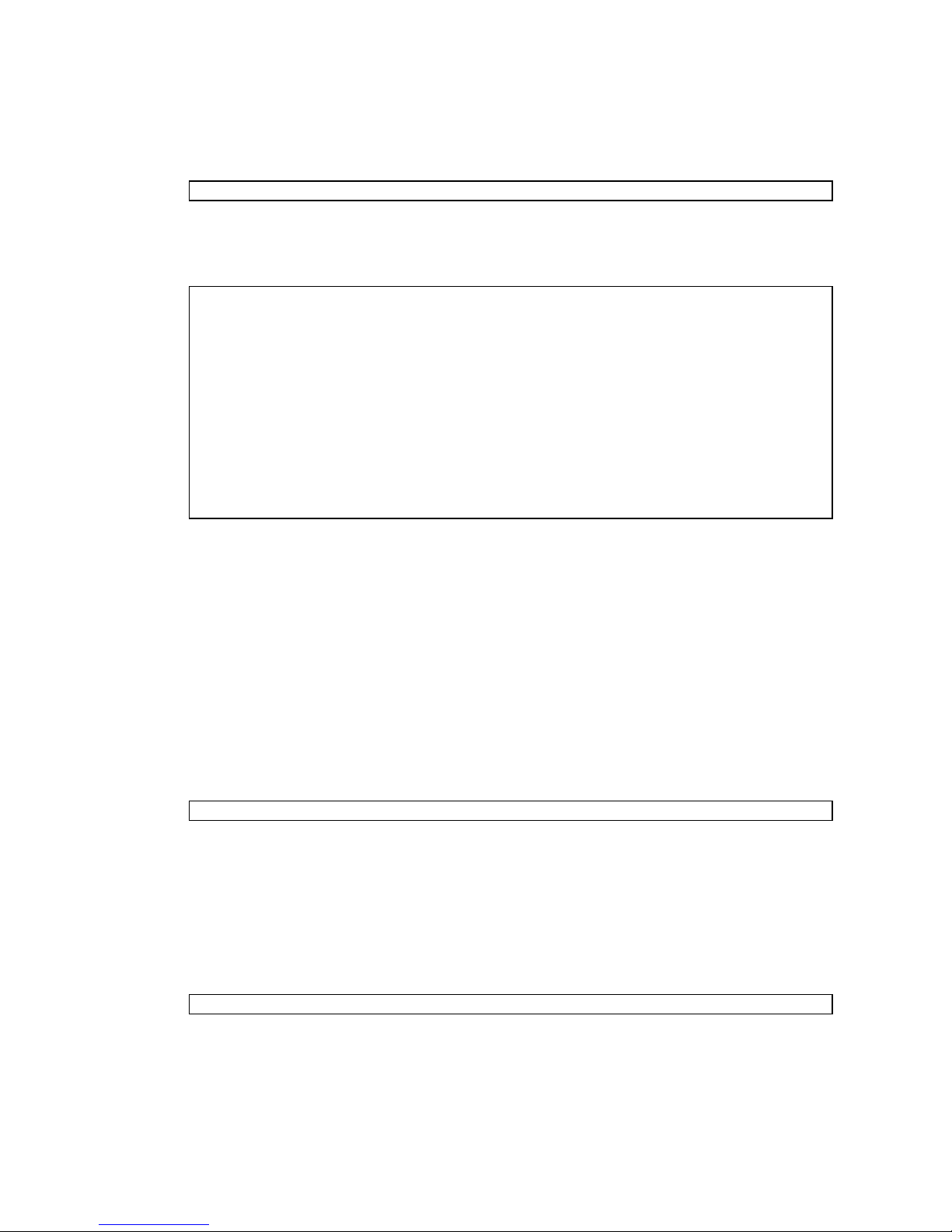
You are prompted to toggle the Operator Panel MODE switch (keyswitch) on the
front of the system. The location of the MODE switch on an entry-level server is
shown in
shown in
horizontally rather than vertically, as shown in
FIGURE 2-1. The location of the MODE switch on a midrange server is
FIGURE 2-2. And the MODE switch on a high-end server is mounted
FIGURE 2-3. The MODE switch has
two positions: Service and Locked.
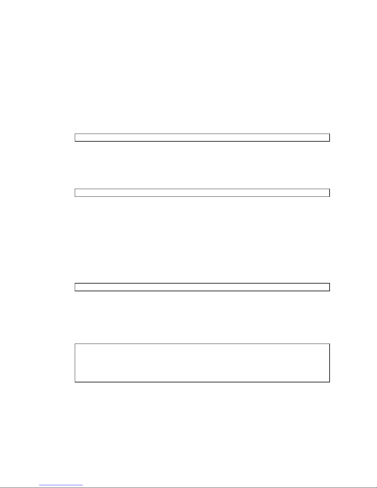
Note – In the following illustrations, the three LEDs appear first, followed by the
POWER button, then the MODE switch.
FIGURE 2-1 Location of the Operator Panel MODE Switch on an Entry-Level Server
Chapter 2 Access Control 13
Page 30

FIGURE 2-2 Location of the Operator Panel MODE Switch on a Midrange Server
FIGURE 2-3 Operator Panel on a High-end Server
You must toggle the MODE switch within one minute of the login prompt or the
login process times out.
2. Toggle the MODE switch using one of two methods, as follows:
■ If the switch is in the Service position, turn it to the Locked position, leave it there
for at least five seconds, and then turn it back to the Service position. Press the
Enter key.
14 SPARC Enterprise Mx000 Servers Administration Guide • August 2009
Page 31

■ If the switch is in the Locked position, turn it to the Service position, leave it there
for at least five seconds, and then turn it back to the Locked position. Press the
Enter key.
When the toggling is successful, you are logged in to the Service Processor shell
as the account default.
XSCF>
As this account has useradm and platadm privileges. you can now configure the
Service Processor or reset passwords.
When the shell session ends, the default account is disabled. When an account is
disabled, it cannot be used to log in at the console. It will then not be possible to
login using this account again except by following this same procedure.
Note – You can use the setupplatform(8) command rather than the following
procedures to perform Service Processor installation tasks. For more information, see
the setupplatform(8) man page.
▼ To Configure an XSCF Password Policy
1. Log in to the XSCF console with useradm privileges.
2. Type the setpasswordpolicy command:
XSCF> setpasswordpolicy option
where option can be one or more of the options described in the
setpasswordpolicy(8) man page.
Note – The password policy applies only to users added after the
setpasswordpolicy(8) command has been executed.
3. Verify that the operation succeeded by typing the showpasswordpolicy
command.
Chapter 2 Access Control 15
Page 32

▼ To Add an XSCF User Account
When you add a new user account, the account has no password, and cannot be
used for logging in until the password is set or Secure Shell public key
authentication is enabled for the user.
1. Log in to the XSCF console with useradm privileges.
2. Type the adduser command:
XSCF> adduser user
where user is the user name you want to add. (See the adduser(8) man page for
rules about the user name.) If you do not specify a User ID (UID) number with the
-u UID option, one is automatically assigned, starting from 100.
3. Verify that the operation succeeded by typing the showuser command.
▼ To Create a Password for an XSCF User
Any XSCF user can set his or her own password. Only a user with useradm
privileges can set another user’s password.
1. Log in to the XSCF console with useradm privileges.
2. Type the password command:
XSCF> password
Please enter your password:
See the password(8) man page for rules about passwords. When typed without
an argument, password sets the current user’s password. To set someone else’s
password, include that person’s user name, for example:
XSCF> password user
Please enter your password:
where user is the user name you want to set the password for. You are prompted
to enter, and then reenter, the password.
▼ To Assign Privileges to an XSCF User
1. Log in to the XSCF console with useradm privileges.
16 SPARC Enterprise Mx000 Servers Administration Guide • August 2009
Page 33

2. Type the setprivileges command:
XSCF> setprivileges user privileges
where user is the user name to assign privileges for, and privileges is one or more
privileges, separated by a space, to assign to this user. The domainadm,
domainmgr, and domainop privileges must include the domain number,
numbers, or range of numbers to associate with a particular user account; for
example,
XSCF> setprivileges user domainadm@1-4, 6, 9
Valid privileges are listed in
TABLE 2-1.
Chapter 2 Access Control 17
Page 34

▼ To Display the Version of Installed Firmware
1. Log in to the XSCF console with platadm or fieldeng privileges.
2. Type the version command:
XSCF> version -c xcp
The XCP version number is displayed. Command output example is:
XSCF> version -c xcp
XSCF#0(Active)
XCP0 (Current): 1080
...
Related Information
For additional information on this chapter’s topics, see:
Resource Information
man pages password(8), version(8), adduser(8), deleteuser(8),
enableuser(8), disableuser(8), showuser(8),
setpasswordpolicy(8), setprivileges(8),
showpasswordpolicy(8), setlookup(8), setldap(8), showldap(8)
SPARC Enterprise
M3000/M4000/M5000/M8000/M9000
Servers XSCF User’s Guide
Access control, user accounts, passwords, firmware update
18 SPARC Enterprise Mx000 Servers Administration Guide • August 2009
Page 35

CHAPTER
3
System Configuration
This chapter describes how to initially configure system services and internal
networks that enable communication between the components of your server.
This chapter contains these sections:
■ About System Services
■ XSCF Shell Procedures for System Configuration
■ Related Information
About System Services
Your server uses various services to enable communication between its components.
See “Preparing for System Configuration” on page 4 for an overview of initial
service configuration.
These sections provide details on system services:
■ DSCP Network Between a Service Processor and a Domain
■ XSCF Network Interfaces
■ Domain Name Service
■ LDAP Service
■ Time Synchronization and NTP Service
■ SNMP Service
■ Additional Services
19
Page 36

DSCP Network Between a Service Processor and a
Domain
The Domain to Service Processor Communications Protocol (DSCP) service provides
a secure TCP/IP- and PPP-based communication link between the Service Processor
and each domain. Without this link, the Service Processor cannot communicate with
the domains.
The Service Processor requires one IP address dedicated to the DSCP service on its
side of the link, and one IP address on each domain’s side of the link. The DSCP
service is a point-to-point link between the Service Processor and each domain.
FIGURE 3-1 illustrates this relationship.
FIGURE 3-1 Relationship of the Service Processor and the DSCP Network to the Domains
First domain
IP address
Second domain
IP address
Third domain
IP address
Fourth domain
IP address
Service
Processor
IP address
DSCP link
DSCP link
DSCP link
DSCP link
DSCP service is not configured by default. You configure and use the service by
specifying IP addresses for the Service Processor and the domains. The IP addresses
should be nonroutable addresses on the network.
The setdscp command provides an interactive mode that displays a prompt for
each DSCP setting you can configure:
■ The network address to be used by the DSCP network for IP addresses
■ The netmask for the DSCP network
■ The Service Processor IP address
■ An IP address for each domain
In a system with redundant Service Processors, the standby Service Processor does
not communicate with the domains. In the event of a failover, the newly active
Service Processor assumes the IP address of the failed-over Service Processor.
20 SPARC Enterprise Mx000 Servers Administration Guide • August 2009
Page 37

DSCP includes its own security measures that prohibit a compromised domain from
compromising other domains or the Service Processor.
The DSCP should only be configured when there are no domains running. If you
change the DSCP configuration while a domain is active, you have to power off the
domain before the Service Processor can communicate with it. See Chapter 4 for
more information on domains.
In a typical DSCP configuration, you enter a network address and netmask using the
setdscp command. The system then configures the Service Processor IP address
and any domain IP addresses according to this formula: the Service Processor gets
an IP address that is the network address +1; and each domain gets an IP address
that is the Service Processor IP address, + the domain ID, +1. For example, if you
enter 10.1.1.0 for the network address, and 255.255.255.0 for the netmask, the
showdscp command displays output similar to the following:
XSCF> showdscp
DSCP Configuration:
Network: 10.1.1.0
Netmask: 255.255.255.0
Location Address
XSCF 10.1.1.1
Domain #00 10.1.1.2
Domain #01 10.1.1.3
Domain #02 10.1.1.4
Domain #03 10.1.1.5
...
This scenario minimizes the range of IP addresses needed for DSCP.
XSCF Network Interfaces
The XSCF network configurable settings include the IP address for the active Service
Processor, IP address for the standby Service Processor, gateway address, netmask,
and network route.
TABLE 3-1 lists the XSCF network interfaces.
Chapter 3 System Configuration 21
Page 38

TABLE 3-1 XSCF Network Interfaces
XSCF Unit Interface Name Description
XSCF Unit 0
xscf#0-lan#0 XSCF LAN#0 (external)
(entry-level, midrange, and
high-end servers)
xscf#0-lan#1 XSCF LAN#1 (external)
xscf#0-if Interface between XSCF Units (ISN: Inter
SCF Network); high-end server only
XSCF Unit 1
xscf#1-lan#0 XSCF LAN#0 (external)
(high-end server only)
xscf#1-lan#1 XSCF LAN#1 (external)
xscf#1-if Interface between XSCF Units (ISN)
lan#0 Takeover IP address for XSCF LAN#0
lan#1 Takeover IP address for XSCF LAN#1
On a high-end server, one Service Processor is configured as active and the other is
configured as standby. The XSCF network between the two Service Processors allows
them to exchange system management information and, in case of failover, to change
roles. When the XSCF unit is configured with redundancy, ISN addresses must be in
the same network subnet.
Optionally, a takeover IP address can be set up, which is hosted on the currently
active Service Processor. External clients can use this takeover IP address to connect
to whichever Service Processor is active. Selection of a takeover IP address does not
affect failover.
When you set or change the information related to the XSCF network, including the
Service Processor host name, DNS domain name, DNS server, IP address, netmask,
or routing information, you must make the changes effective in XSCF and reset the
Service Processor. This is done with the applynetwork and rebootxscf
commands.
You configure the XSCF network with these commands:
■ setnetwork
■ setroute
■ sethostname (if using DNS)
■ setnameserver (if using DNS)
■ applynetwork
22 SPARC Enterprise Mx000 Servers Administration Guide • August 2009
Page 39

Once you have configured the XSCF network, it requires no day-to-day
management.
Domain Name Service
The Domain Name Service (DNS) allows computers on a network to communicate
with each other by using centrally maintained DNS names instead of locally stored
IP addresses. If you configure the Service Processor to use the DNS service, it “joins”
the DNS community and can communicate with any other computer on the network
through its DNS server.
There are no defaults for this service. To configure the Service Processor to use DNS,
you must specify the Service Processor host name, and the DNS server name and IP
address.
You can configure the Service Processor DNS service with these commands:
■ sethostname
■ setnameserver
On a server with dual Service Processors, the domain name is common for both
Service Processors. A host name can be specified for each Service Processor. Setting a
different host name for each Service Processor does not disable failover.
Once you have configured the Service Processor to use the DNS service, it does not
require day-to-day management.
LDAP Service
The LDAP service stores user authentication and privilege settings on a server so
that individual computers on the network do not have to store the settings.
By default, the Service Processor stores user passwords and privileges locally.
Account information for users who have access to the Service Processor are stored
on the Service Processor itself. (Authentication and privilege lookups for the server’s
domains are provided by the Solaris OS.)
However, if you want to have authentication and privilege lookups performed by an
LDAP server, you can set up the Service Processor to be an LDAP client.
The general process for setting up the Service Processor as an LDAP client is:
1. Enabling the LDAP service.
2. Providing the LDAP server configuration information:
■ The IP address or hostname, and port, of the primary LDAP directory
Chapter 3 System Configuration 23
Page 40

■ Optional: The IP address or hostname, and port, of up to two alternative LDAP
directories
■ The distinguished name (DN) of the search base to use for lookup
■ Whether Transport Layer Security (TLS) is to be used
3. Verifying that the LDAP service is working.
On the LDAP server, you create an LDAP schema with privilege properties. The
schema contains the following:
CODE EXAMPLE 3-1 LDAP Schema
attributetype ( 1.3.6.1.1.1.1.40 NAME ’spPrivileges’
DESC ’Service Processor privileges’
SYNTAX 1.3.6.1.4.1.1466.115.121.1.26
SINGLE-VALUE )
objectclass ( 1.3.6.1.1.1.2.13 NAME ’serviceProcessorUser’ SUP top
AUXILIARY
DESC ’Service Processor user’
MAY spPrivileges )
You also add the following required attributes for each user on the LDAP server, as
shown in
TABLE 3-2.
TABLE 3-2 LDAP LDIF File Attributes
Field Name Description
spPrivileges A valid privilege on the Service Processor
uidNumber The user ID number on the Service Processor. The
uidnumber must be greater than 100. Use the showuser
command to display UIDs.
A sample file entry is:
CODE EXAMPLE 3-2 Sample LDAP LDIF File Attributes
spPrivileges: platadm
uidNumber: 150
See the Solaris OS documentation collection for more information on LDAP servers.
If the LDAP client is configured and enabled on the Service Processor, lookups are
first performed locally, and then through the LDAP server. If you execute the
setprivileges command for a user without specifying privileges, the command
24 SPARC Enterprise Mx000 Servers Administration Guide • August 2009
Page 41

deletes any local privilege data for that user. Subsequently, the user’s privileges will
be looked up in LDAP, if LDAP privilege lookup is enabled. If you specify privilege
as none, that user will have no privileges, regardless of privilege data in LDAP.
These commands manage the Service Processor LDAP service:
■ setlookup
■ setldap
Note that passwords stored in the LDAP repository must use either UNIX crypt or
MD5 encryption schemes.
Once you have configured the Service Processor to use the LDAP service, it does not
require day-to-day management.
Time Synchronization and NTP Service
The Network Time Protocol (NTP) provides the correct timestamp for all systems on
a network by synchronizing the clocks of all the systems. NTP service is provided by
an NTP daemon.
To use the NTP service, the Service Processor can be set up as an NTP client, using
the services of a remote NTP server. The Service Processor also can be set up as an
NTP server, as can an external resource.
Note – Check the Product Notes for your server, which may contain important
information about using the XSCF as NTP server.
TABLE 3-3 shows how the time is synchronized.
TABLE 3-3 XSCF and Domain Time Synchronization
Entity Primary NTP Server Time Synchronization Method
XSCF No connection The XSCF time is the time in the initial system setting or the
time set with the setdate command.
External NTP server XSCF operates as an NTP client. The XSCF time is adjusted to
the time of the external NTP server.
Domain XSCF XSCF operates as the NTP server. The domain time is
adjusted to the time of the XSCF.
External NTP server The domain time is adjusted to the time of the external NTP
server.
When domains are powered on, they synchronize their clocks to the NTP server.
Chapter 3 System Configuration 25
Page 42

If the domain and the Service Processor are using the same time source, one benefit
is that events logged in the Solaris OS and on the Service Processor can be correlated
based on their timestamp. If the domain and Service Processor use different NTP
servers, their times may drift, and correlating log files could become difficult. If you
connect a domain to an NTP server other than the one used by the Service Processor,
be sure both are high-rank NTP servers that provide the same degree of accuracy.
The XSCF can be used as NTP server only for domains on the same platform.
Every NTP server and every NTP client must have an ntp.conf file, in
/etc/inet/ntp.conf. The Service Processor has a default ntp.conf file. If you
are using NTP, you must create an ntp.conf file on each domain.
If you are using the Service Processor as the NTP server for the domains, create an
ntp.conf file on each domain similar to the following:
CODE EXAMPLE 3-3 Sample ntp.conf File for a Domain using XSCF as NTP Server
server ip_address
slewalways yes
disable pll
enable auth monitor
driftfile /var/ntp/ntp.drift
statsdir /var/ntp/ntpstats/
filegen peerstats file peerstats type day enable
filegen loopstats file loopstats type day enable
filegen clockstats file clockstats type day enable
where ip_address is the IP address you configured for the Service Processor on the
DSCP network. To display the Service Processor’s IP address, use the showdscp -s
command.
If you are using an external NTP server for the domains, see the xntpd(1M) man
page or to the Solaris OS documentation collection for information on creating the
ntp.conf file for each domain.
SNMP Service
A Simple Network Management Protocol (SNMP) agent can be configured and
enabled on the Service Processor. The Service Processor SNMP agent monitors the
state of the system hardware and domains, and exports the following information to
an SNMP manager:
■ System information such as chassis ID, platform type, total number of CPUs, and
total memory
■ Configuration of the hardware
26 SPARC Enterprise Mx000 Servers Administration Guide • August 2009
Page 43

■ Dynamic reconfiguration information, including which domain-configurable units
are assigned to which domains
■ Domain status
■ Power status
■ Environmental status
The Service Processor SNMP agent can supply system information and fault event
information using public MIBs. SNMP managers, for example, a third-party
manager application, use any Service Processor network interface with the SNMP
agent port to communicate with the agent. The SNMP agent supports concurrent
access from multiple users through SNMP managers.
By default, the SNMP agent uses version 3 (v3) of the SNMP protocol. SNMP v3 is
secure, requiring an authentication protocol, authentication password, and
encryption password. The valid authentication protocols are MD5 and SHA (secure
hash algorithm). You can also configure your server to accept earlier SNMP versions
1 and 2.
The SNMP agent includes the v3 utilities for user management, the User Security
Model (USM), and for view access control, the View Access Control Model (VACM).
You can change the configuration of SNMP agent traps, USM user accounts, and
VACM information.
Initial SNMP v3 configuration includes:
1. Creating USM user information
2. Creating VACM access control information (group, view, and access)
Using VACM requires a basic knowledge of SNMP and MIBs. See the Solaris
System Management Agent Administration Guide and to the SPARC Enterprise
M3000/M4000/M5000/M8000/M9000 Servers XSCF User’s Guide for information.
3. Configuring the SNMP agent
4. Enabling the SNMP agent
5. Setting up your SNMP manager application to communicate with the Service
Processor SNMP agent based on the configuration you used for the agent, namely,
user, port, and trap information.
The SNMP agent is active only on the active Service Processor. In the event of
failover, the SNMP agent is restarted on the newly active Service Processor.
Chapter 3 System Configuration 27
Page 44

Additional Services
This section describes HTTPS, Telnet, SMTP, and SSH services, and altitude settings.
This section does not cover all the optional services and settings for the Service
Processor that you might want to set up and use at a later date. For example, you
can set up mirrored memory mode using the setupfru command. See the SPARC
Enterprise M3000/M4000/M5000/M8000/M9000 Servers XSCF User’s Guide for
information on day-to-day administration and management tasks.
HTTPS Service
Hypertext Transfer Protocol (HTTP) over an authenticated/encrypted connection
allows you to use the XSCF web browser securely. This is called the HTTPS service.
Authentication is provided with a certificate authority and private keys. To use the
HTTPS service, you must enable it, and provide an optional port number. The
default port is 443. To enable HTTPS service, use the sethttps command.
Telnet Service
Telnet service is disabled by default on the Service Processor. To enable it, use the
settelnet command. Telnet provides an alternative for those sites that do not have
ssh.
SMTP Service
Simple Mail Transfer Protocol (SMTP) service is controlled by these commands:
■ showsmtp
■ setsmtp
The authentication mechanisms allowed by the mail server are pop, smtp-auth,or
none (the default). The SMTP authentications supported are plain and login.
SSH Service
SSH service is disabled by default. To enable it, use the setssh command. A host
public key is required for SSH service.
28 SPARC Enterprise Mx000 Servers Administration Guide • August 2009
Page 45

Altitude Setting
The altitude for your server is set to 0 meters by default. To set it for the actual
altitude of your server, use the setaltitude command. Executing this command
causes the server to adjust the temperature thresholds it uses to protect the system
so it can more accurately detect any abnormality in the intake air temperature.
However, even if you do not set the altitude, any abnormality in air temperature,
such as CPU temperature, can still be detected. As server temperature limits are set
to protect domain hardware, execute the setaltitude command before powering
on any domain. See setaltitude(8).
Note – A modification of the altitude value takes effect only after you subsequently
execute the rebootxscf command and reset XSCF. See rebootxscf(8).
XSCF Shell Procedures for System
Configuration
This section describes these procedures:
■ To Configure the DSCP Network
■ To Display DSCP Network Configuration
■ To Configure the XSCF Network Interfaces
■ To Configure the XSCF Network Route Information
■ To Set Or Reset the XSCF Network
■ To Display XSCF Network Configuration
■ To Set the Service Processor Host Name and DNS Domain Name
■ To Set the Service Processor’s DNS Name Server
■ To Enable or Disable Use of an LDAP Server for Authentication and Privilege
Lookup
■ To Configure the XSCF as an LDAP Client
■ To Configure the XSCF as an NTP Client
■ To Display the NTP Configuration
■ To Set the Timezone, Daylight Saving Time, Date, and Time Locally on the Service
Processor
■ To Create a USM User Known to the SNMP Agent
■ To Display USM Information for the SNMP Agent
Chapter 3 System Configuration 29
Page 46

■ To Create a VACM Group
■ To Create a VACM View
■ To Give a VACM Group Access to a VACM View
■ To Display VACM Information for the SNMP Agent
■ To Configure the SNMP Agent to Send Version 3 Traps to Hosts
■ To Enable the SNMP Agent
■ To Display SNMP Agent Configuration
■ To Enable or Disable the Service Processor HTTPS Service
■ To Enable or Disable the Service Processor Telnet Service
■ To Configure the Service Processor SMTP Service
■ To Enable or Disable the Service Processor SSH Service
■ To Generate a Host Public Key for SSH Service
Note – You can use the setupplatform(8) command rather than the following
procedures to perform network installation tasks. For more information, see the
setupplatform(8) man page.
▼ To Configure the DSCP Network
1. Log in to the XSCF console with platadm or fieldeng privileges.
2. Type the setdscp command.
You can use one of two methods, as follows:
■ Use the setdscp command with the -y -i address -m netmask options:
XSCF> setdscp -y -i address -m netmask
For example:
XSCF> setdscp -y -i 10.1.1.0 -m 255.255.255.0
30 SPARC Enterprise Mx000 Servers Administration Guide • August 2009
Page 47

■ Use the setdscp command with no options (interactive mode).
You are prompted to enter all the DSCP IP addresses sequentially. A command
output example of this interactive mode is:
XSCF> setdscp
DSCP network [0.0.0.0] > 10.1.1.0
DSCP netmask [255.0.0.0] > 255.255.255.0
XSCF address [10.1.1.1] > [Enter]
Domain #00 address [10.1.1.2] > [Enter]
Domain #01 address [10.1.1.3] > [Enter]
Domain #02 address [10.1.1.4] > [Enter]
Domain #03 address [10.1.1.5] > [Enter]
Domain #04 address [10.1.1.6] > [Enter]
Domain #05 address [10.1.1.7] > [Enter]
Domain #06 address [10.1.1.8] > [Enter]
Domain #07 address [10.1.1.9] > [Enter]
Domain #08 address [10.1.1.10] > [Enter]
...
Commit these changes to the database (y|n)?
a. For each prompt, press the Enter key to accept the displayed value, or type
a new value followed by the Enter key.
b. To save your changes, enter Y. To cancel the changes, enter N.
3. Verify the operation with the showdscp command.
▼ To Display DSCP Network Configuration
1. Log in to the XSCF console with platadm, platop,orfieldeng privileges, or
domainadm, domainop,ordomainmgr privileges for a specific domain.
Chapter 3 System Configuration 31
Page 48
2. Type the showdscp command:
XSCF> showdscp
Command output example for a DSCP network of 10.1.1.0 and a DSCP netmask
of 255.255.255.0 is:
XSCF> showdscp
DSCP Configuration:
Network: 10.1.1.0
Netmask: 255.255.255.0
Location Address
XSCF 10.1.1.1
Domain #00 10.1.1.2
Domain #01 10.1.1.3
Domain #02 10.1.1.4
Domain #03 10.1.1.5
...
▼ To Configure the XSCF Network Interfaces
Settings to configure the XSCF network must be applied to XSCF, and the Service
Processor must be reset, before the settings become effective. See “To Set Or Reset
the XSCF Network” on page 34.
1. Log in to the XSCF console with platadm privileges.
2. Type the setnetwork command:
a. To set the network interface, netmask, and IP address:
XSCF> setnetwork interface [-m addr] address
where interface specifies the network interface to be set, -m addr specifies the
netmask address of the network interface, and address specifies the IP address
of the network interface. If the -m option is omitted, the netmask
corresponding to the IP address is set. See
TABLE 3-1 for valid interface names.
The following example sets the IP address and netmask for the interface XSCFLAN#0 on XSCF Unit 1 in a high-end server:
XSCF> setnetwork xscf#1-lan#0 -m 255.255.255.0 192.168.11.10
32 SPARC Enterprise Mx000 Servers Administration Guide • August 2009
Page 49

b. To enable the specified network interface:
XSCF> setnetwork -c [up|down] interface
where -c specifies whether to enable or disable the specified network
interface, and interface specifies the network interface to be enabled.
Note – When the XSCF unit is configured with redundancy, ISN addresses must be
in the same network subnet.
For additional information on the setnetwork command, including specifying
takeover IP addresses, see the setnetwork(8) man page or to the SPARC
Enterprise M3000/M4000/M5000/M8000/M9000 Servers XSCF User’s Guide.
3. Verify the operation with the shownetwork command.
▼ To Configure the XSCF Network Route
Information
Settings to configure the XSCF network must be applied to XSCF, and the Service
Processor must be reset, before the settings become effective. See “To Set Or Reset
the XSCF Network” on page 34.
1. Log in to the XSCF console with platadm privileges.
2. Type the setroute command:
XSCF> setroute -c [add|del] -n address [-m address] [-g address] interface
where -c specifies whether to add or delete routing information, -n address
specifies the IP address to which routing information is forwarded, -m address
specifies the netmask address to which routing information is forwarded, -g
address specifies the gateway address, and interface specifies the network interface
to be set with routing information. See
For additional information on the setroute command, including specifying
takeover IP addresses, see the setroute(8) man page or to the SPARC Enterprise
M3000/M4000/M5000/M8000/M9000 Servers XSCF User’s Guide.
TABLE 3-1 for valid interface names.
Chapter 3 System Configuration 33
Page 50
▼ To Set Or Reset the XSCF Network
When you set or change the Service Processor host name, DNS domain name, DNS
server, IP address, netmask, or routing information, the settings must be applied to
XSCF, and the Service Processor must be reset, before the settings become effective.
1. Log in to the XSCF console with platadm privileges.
2. Type the applynetwork command:
XSCF> applynetwork
The applynetwork command displays the information that has been set for the
XSCF network, and asks you to apply the settings.
3. Execute the rebootxscf command to make the settings effective:
XSCF> rebootxscf
4. Verify the operation with the shownetwork command.
▼ To Display XSCF Network Configuration
1. Log in to the XSCF console.
2. Type the shownetwork command:
XSCF> shownetwork -a | interface
where -a displays information for all XSCF network interfaces, and interface
displays information for a specific XSCF network interface name, in the format
xscf#x-y.
Command output example for the XSCF Unit #0, LAN#1 is:
XSCF> shownetwork xscf#0-lan#1
Link encap:Ethernet HWaddr 00:00:00:12:34:56
inet addr:192.168.10.11 Bcast:192.168.10.255 Mask:255.255.255.0
UP BROADCAST RUNNING MULTICAST MTU:1500 Metric:1
...
34 SPARC Enterprise Mx000 Servers Administration Guide • August 2009
Page 51

▼ To Set the Service Processor Host Name and
DNS Domain Name
1. Log in to the XSCF console with platadm privileges.
2. Type the sethostname command:
a. To set the Service Processor host name:
XSCF> sethostname xscfu hostname
where xscfu can be xscf#0 (XSCF Unit 0) or xscf#1 (XSCF Unit 1 in a highend server); hostname is the host name to be set for the specified Service
Processor (XSCF Unit).
b. To set the Service Processor domain name:
XSCF> sethostname -d domainname
3. To verify the operation, type the showhostname command.
XSCF> showhostname -a | xscfu
where -a displays the host names for all XSCF Units, and xscfu displays
information for a specific XSCF Unit, either xscf#0 or xscf#1.
▼ To Set the Service Processor’s DNS Name Server
1. Log in to the XSCF console with platadm privileges.
2. Type the setnameserver command, followed by one or more IP addresses
separated by a comma:
XSCF> setnameserver ip_address
3. To verify the operation, type the shownameserver command.
XSCF> shownameserver
Chapter 3 System Configuration 35
Page 52

▼ To Enable or Disable Use of an LDAP Server for
Authentication and Privilege Lookup
1. Log in to the XSCF console with useradm privileges.
2. Type the setlookup command:
XSCF> setlookup -a local|ldap
XSCF> setlookup -p local|ldap
The -a option sets the authentication lookup to either local or in LDAP; the -p
option sets the privileges lookup to either local or in LDAP. When local is
specified, lookup is only done locally; when ldap is specified, lookup is first done
locally, then in LDAP if not found locally.
3. To verify the operation, type the showlookup command.
XSCF> showlookup
▼ To Configure the XSCF as an LDAP Client
Make sure you have added an LDAP privileges schema to the LDAP server, and
attributes for each user on the LDAP server. See
CODE EXAMPLE 3-2 for information.
1. Log in to the XSCF console with useradm privileges.
2. Type the setldap command:
XSCF> setldap [-b bind] [-B baseDN] [-c certchain] [-p] [-s servers] [t user] -T timeout
where bind is the bind name, baseDN is the base Distinguished Name, certchain is
an LDAP server certificate chain, -p sets the password to use when binding to the
LDAP server (you are prompted for the password), servers sets the primary and
secondary LDAP servers and ports, user tests the server connection and password
for the specified user, and timeout is the maximum amount of time allowed for an
LDAP search before search results are returned. For more information on LDAP,
see the setldap(8) man page, to the SPARC Enterprise
M3000/M4000/M5000/M8000/M9000 Servers XSCF User’s Guide, and to the Solaris
OS documentation collection.
3. To verify the operation, type the showldap command.
XSCF> showldap
CODE EXAMPLE 3-1 and
36 SPARC Enterprise Mx000 Servers Administration Guide • August 2009
Page 53

▼ To Configure the XSCF as an NTP Client
If you are using NTP, an ntp.conf file must be created on the domains. See “Time
Synchronization and NTP Service” on page 25 for information. This section describes
how to set the XSCF as an NTP client.
1. Log in to the XSCF console with platadm privileges.
2. Type the setntp command:
XSCF> setntp -c add address
where address is the IP address of the NTP server.
3. Reset the Service Processor with the rebootxscf command to make the
settings effective:
XSCF> rebootxscf
4. To verify the operation, type the showntp command.
XSCF> showntp -a
▼ To Configure the XSCF as an NTP Server
If you are using NTP, an ntp.conf file must be created on the domains. See “Time
Synchronization and NTP Service” on page 25 for information. This section describes
how to set the XSCF as an NTP server.
Note – Check the Product Notes for your server, which may contain important
information about using the XSCF as NTP server.
1. Log in to the XSCF console with platadm privileges.
2. Type the setntp command:
XSCF> setntp -c stratum -i stratum_no
where stratum_no is the stratum value for the NTP server. The default value is 5.
3. Reset the Service Processor with the rebootxscf command to make the
settings effective:
XSCF> rebootxscf
Chapter 3 System Configuration 37
Page 54

4. To verify the operation, type the showntp command.
XSCF> showntp -s
▼ To Display the NTP Configuration
1. Log in to the XSCF console.
2. Type the showntp command:
XSCF> showntp {-a | -l | address | -s}
where the -a option displays all the NTP servers configured for use, the -l
option displays time synchronization information, address is the IP address of the
NTP server for which information is to be displayed, and the -s option displays
the stratum value of the NTP server.
▼ To Set the Timezone, Daylight Saving Time,
Date, and Time Locally on the Service Processor
1. Log in to the XSCF console with platadm or fieldeng privileges.
2. Type the settimezone command:
a. To display the timezones that you can set:
XSCF> settimezone -c settz -a
b. To set the timezone:
XSCF> settimezone -c settz -s timezone
where timezone is the timezone you want to set. For more information on the
settimezone command, including setting Daylight Saving Time, see the
settimezone(8) man page or to the Reference Manual.
3. To verify the operation, type the showtimezone command.
XSCF> showtimezone
38 SPARC Enterprise Mx000 Servers Administration Guide • August 2009
Page 55

4. Type the setdate command:
XSCF> setdate -s date
where date is the date and time you want to set. For more information on the
setdate command, see the setdate(8) man page or to the Reference Manual.
5. After specifying the date, you are prompted to reset the Service Processor, so
that the date and time become effective. Type Y to reset the Service Processor.
6. To verify the operation, type the showdate command.
XSCF> showdate
▼ To Create a USM User Known to the SNMP
Agent
A USM user known to the SNMP agent is not required to have a regular user
account on the Service Processor.
1. Log in to the XSCF console with platadm privileges.
2. Type the setsnmpusm command.
You can use one of two methods to add USM users, as follows:
■ To add a new user, use the create argument:
XSCF> setsnmpusm create -a authentication_protocol [-p authentication_password]
[-e encryption_password] user
where authentication_protocol is either MD5 or SHA, authentication_password is the
authentication password (must be equal to or greater than 8 characters),
encryption_password is the encryption password, and
user is the user name to be
known to the agent for subsequent SNMP communication. If you do not specify
the passwords, you are prompted to enter them.
■ To add a new user with the same settings as an existing user, use the clone
argument:
XSCF> setsnmpusm clone -u clone_user user
where
user name to be created with the same settings as the valid
clone_user is a valid user name known to the SNMP agent, and user is the
clone_user. Use the
setsnmpusm password command to change either or both passwords for the
cloned user, if desired.
Chapter 3 System Configuration 39
Page 56

3. To verify the operation, type the showsnmpusm command.
▼ To Display USM Information for the SNMP
Agent
1. Log in to the XSCF console with platadm or platop privileges.
2. Type the showsnmpusm command:
XSCF> showsnmpusm
Command output example is:
XSCF> showsnmpusm
Username Auth Protocol
============= =============
jsmith SHA
sue MD5
▼ To Create a VACM Group
1. Log in to the XSCF console with platadm privileges.
2. Type the setsnmpvacm command:
XSCF>
where
the name of the group to create for the specified user for view access.
3. To verify the operation, type the showsnmpvacm command.
setsnmpvacm creategroup -u username groupname
username is a valid user name known to the SNMP agent, and groupname is
▼ To Create a VACM View
1. Log in to the XSCF console with platadm privileges.
40 SPARC Enterprise Mx000 Servers Administration Guide • August 2009
Page 57

2. Type the setsnmpvacm command:
XSCF> setsnmpvacm createview -s OID_subtree [-m OID_Mask] viewname
where
entire MIB tree, and can be limited to certain portions of the tree by using the
optional
agent exported MIB information. View access is read-only for the agent.
3. To verify the operation, type the showsnmpvacm command.
OID_subtree is the MIB OID subtree for the view (values start at .1 for the
OID_Mask), and viewname is the name of the view to create for the SNMP
▼ To Give a VACM Group Access to a VACM View
1. Log in to the XSCF console with platadm privileges.
2. Type the setsnmpvacm command:
XSCF>
where
group name.
3. To verify the operation, type the showsnmpvacm command.
setsnmpvacm createaccess -r viewname groupname
viewname is a valid SNMP agent view, and groupname is a valid SNMP agent
▼ To Display VACM Information for the SNMP
Agent
1. Log in to the XSCF console with platadm or platop privileges.
Chapter 3 System Configuration 41
Page 58

2. Type the showsnmpvacm command:
XSCF> showsnmpvacm
Command output example is:
XSCF> showsnmpvacm
Groups
Groupname Username
============= =============
admin jsmith, bob
Views
View Subtree Mask Type
============= ======= ====== =========
all_view .1 ff include
Access
View Group
============= =============
all_view admin
▼ To Configure the SNMP Agent to Send Version 3
Traps to Hosts
1. Log in to the XSCF console with platadm privileges.
2. Type the setsnmp command:
XSCF> setsnmp addv3traphost -u username -r authentication_protocol {-n
engine_id | -i} [-a authentication_password] [-e encryption_password] [-p
trap_port] traphost
where username is a user known to the SNMP agent, authentication_protocol is
either MD5 or SHA, engine_id is the identifier of the local agent sending the trap,
which must match the engine_id expected by the host, -i asks for
acknowledgement from the receiving host, authentication_password is the
authentication password (must be equal to or greater than 8 characters),
42 SPARC Enterprise Mx000 Servers Administration Guide • August 2009
Page 59

encryption_password is the encryption password, trap_port is the listening port for
the SNMP agent (the default is 161), and traphost is the host name where the
SNMP manager application is running.
If you do not specify the passwords, you are prompted to enter them.
3. To verify the operation, type the showsnmp command.
For additional options with the setsnmp command, including information on
configuring your system to accept SNMP version 1 or 2 traps, see the setsnmp(8)
man page.
▼ To Enable the SNMP Agent
1. Log in to the XSCF console with platadm privileges.
2. Type the setsnmp command:
XSCF> setsnmp enable
3. To verify the operation, type the showsnmp command.
Make sure that your SNMP manager application can communicate with the Service
Processor SNMP agent based on the configuration you used for the agent, namely,
user, port, and trap information.
▼ To Display SNMP Agent Configuration
1. Log in to the XSCF console with platadm or platop privileges.
Chapter 3 System Configuration 43
Page 60

2. Type the showsnmp command:
XSCF> showsnmp
Command output example is:
XSCF> showsnmp
Agent Status: Enabled
Agent Port: 161
System Location: Unknown
System Contact: Unknown
System Description: Unknown
Trap Hosts:
Hostname Port Type Community String Username Auth Protocol
-------- ---- ---- ---------------- -------- -----------host1 162 v3 n/a user1 SHA
SNMP V1/V2c: None
▼ To Enable or Disable the Service Processor
HTTPS Service
1. Log in to the XSCF console with platadm privileges.
2. Optionally, display the current status of the Service Processor HTTPS Service:
XSCF> showhttps
3. Type the sethttps command:
XSCF> sethttps -c function
where function is either enable or disable. The HTTPS service starts
immediately after being enabled, and stops immediately after being disabled.
For additional options with the sethttps command, including information on
certificates and private keys, see the sethttps(8) man page or to the SPARC
Enterprise M3000/M4000/M5000/M8000/M9000 Servers XSCF User’s Guide.
44 SPARC Enterprise Mx000 Servers Administration Guide • August 2009
Page 61

▼ To Enable or Disable the Service Processor
Telnet Service
1. Log in to the XSCF console with platadm privileges.
2. Optionally, display the current status of the Service Processor Telnet Service:
XSCF> showtelnet
3. Type the settelnet command:
XSCF> settelnet -c function
where function is either enable or disable. The Telnet service starts
immediately after being enabled, and stops immediately after being disabled.
▼ To Configure the Service Processor SMTP
Service
1. Log in to the XSCF console with platadm privileges.
2. Optionally, display the current status of the Service Processor SMTP Service:
XSCF> showsmtp
3. Type the setsmtp command:
XSCF> setsmtp
You are prompted to enter the name of the SMTP mail server to be used, the port
number to be used (default is port 25), the authentication mechanism (default is
none) and the Reply Address. You must specify a valid email address.
▼ To Enable or Disable the Service Processor SSH
Service
1. Log in to the XSCF console with platadm privileges.
2. Optionally, display the current status of the Service Processor SSH Service:
XSCF> showssh
Chapter 3 System Configuration 45
Page 62

3. Type the setssh command:
XSCF> setssh -c function
where function is either enable or disable. You must generate a host public key
to use SSH.
▼ To Generate a Host Public Key for SSH Service
1. Log in to the XSCF console with platadm privileges.
2. Type the setssh command:
XSCF> setssh -c genhostkey
For additional options with the setssh command, including information on adding
or deleting user public keys, see the setssh(8) man page or to the SPARC Enterprise
M3000/M4000/M5000/M8000/M9000 Servers XSCF User’s Guide.
▼ To Set the Altitude on the Service Processor
1. Log in to the XSCF console with fieldeng privileges.
2. Type the setaltitude command:
XSCF>
where
hundred meters.
3. To verify the operation, type the showaltitude command.
setaltitude -s altitude=value
value is a unit of meters. The unit of meters is rounded off to the nearest
46 SPARC Enterprise Mx000 Servers Administration Guide • August 2009
Page 63

Related Information
For additional information on this chapter’s topics, see:
Resource Information
man pages showdscp(8), setdscp(8), showloginlockout(8),
setloginlockout(8), shownetwork(8),
setnetwork(8), applynetwork(8),
showhostname(8), sethostname(8), setroute(8),
showroute(8), setdate(8), showdate(8),
showntp(8), setntp(8), xntpd(1M), ntpq(1M),
ntpdate(1M), setnameserver(8),
shownameserver(8), sethostname(8),
showhostname(8), showlookup(8), setlookup(8),
showldap(8), setldap(8), showsnmp(8), setsnmp(8),
setsnmpusm(8), setsnmpvacm(8), showsnmpusm(8),
showsnmpvacm(8), showhttps(8), sethttps(8),
showtelnet(8), settelnet(8), showssh(8),
setssh(8), showsmtp(8), setsmtp(8),
setaltitude(8), showaltitude(8), rebootxscf(8),
dumpconfig(8), restoreconfig(8)
SPARC Enterprise M3000/M4000/M5000/M8000/M9000
Servers XSCF User’s Guide
Solaris System Management Agent Administration Guide SNMP
Topics covered in this chapter and additional
information on day-to-day administration
Chapter 3 System Configuration 47
Page 64

48 SPARC Enterprise Mx000 Servers Administration Guide • August 2009
Page 65

CHAPTER
4
Domain Configuration
This chapter describes how to set up and manage domains with XSCF firmware. On
your server, by default from the factory, there is one domain with the Solaris OS
installed, and its Domain Identification Number (DID) is 0 (zero).
This chapter contains these sections:
■ About Domains
■ XSCF Shell Procedures for Domain Configuration
■ Related Information
About Domains
These sections provide details on domain configuration:
■ Domains and System Boards
■ SPARC64 VI and SPARC64 VII Processors and CPU Operational Modes
■ Domain Resource Assignment
■ Domain Component List and Logical System Boards
■ Overview of Steps for Domain Configuration
■ Domain Configuration Example
■ Domain Communication
■ CD-RW/DVD-RW Drive or Tape Drive Assignment
■ Backup and Restore Operations
■ Dynamic Reconfiguration
49
Page 66

Domains and System Boards
A domain is an independent system resource that runs its own copy of the Solaris
OS. Domains divide a system’s total resources into separate units that are not
affected by each other’s operations. Domains can be used for different types of
processing; for example, one domain can be used to test new applications, while
another domain can be used for production purposes.
The entry-level server supports only a single domain, one CPU, 8 dual inline
memory modules (DIMMs), and I/O. Midrange and high-end servers support
multiple domains and one to 16 physical system boards (PSBs). One PSB consists of
4 CPUs, 32 DIMMs, and I/O. The I/O varies by server, and can include PCIe slots,
PCI-X slots, and built-in I/O.
Entry-level servers have a fixed system board configuration by default; you do not
need to reconfigure the system board.
To use a PSB in your midrange or high-end server, the hardware resources on the
board must be logically divided and reconfigured as eXtended System Boards
(XSBs). There are two modes of XSBs:
■ Uni-XSB
■ A PSB logically undivided and configured into one XSB
■ Contains all the resources on the board: 4 CPUs, 32 DIMMs, and I/O on a
midrange and high-end server; 1 CPU, 8 DIMMs, and I/O on an entry-level
server.
The following figures show a PSB in Uni-XSB mode on entry-level, midrange, and
high-end servers.
Note – On midrange and high-end servers, the CPU modules and memory modules
are known as the CPU/memory board unit (CMU), and the I/O devices are
contained in the I/O unit (IOU). The terms CMU and IOU do not have meaning for
entry-level servers.
50 SPARC Enterprise Mx000 Servers Administration Guide • August 2009
Page 67
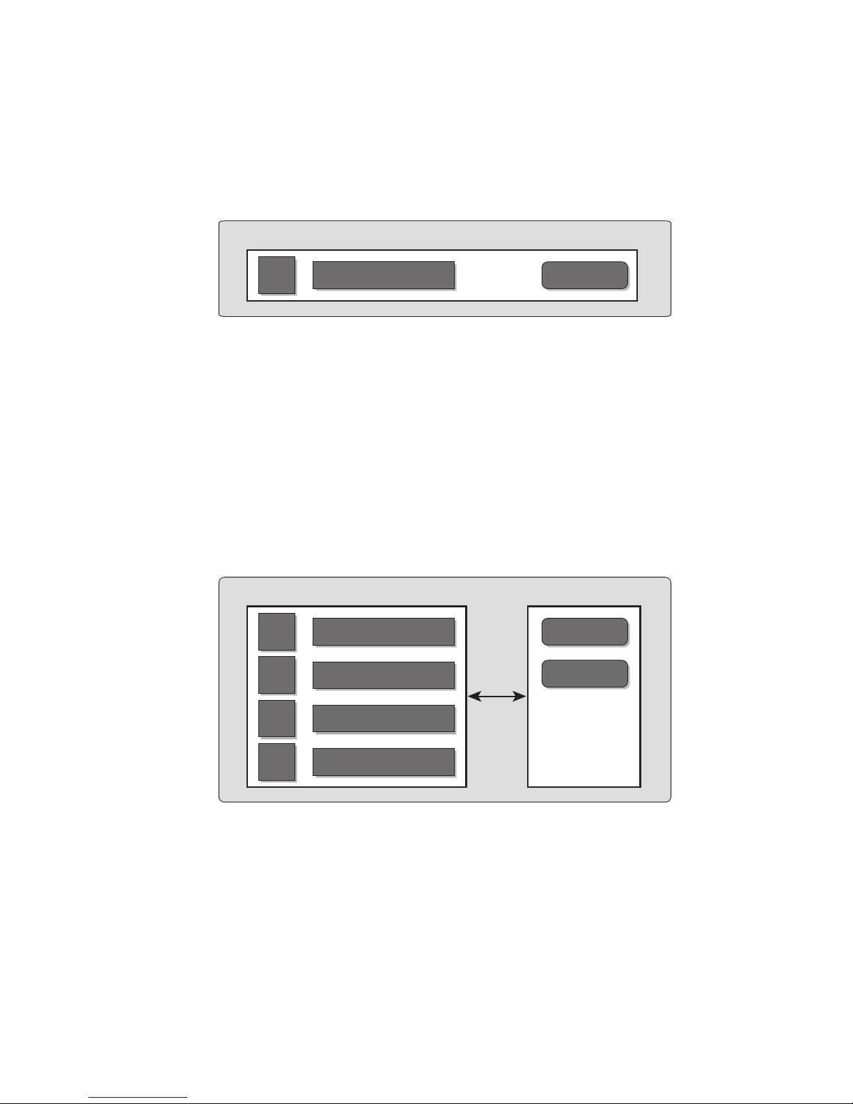
FIGURE 4-1 A Physical System Board in Uni-XSB Mode on an Entry-Level Server
Uni-XSB㩷㫄㫆㪻㪼㩷㩿㪽㫀㫏㪼㪻㪀
1 physical system board with
1 CPU, 8 DIMMs, and I/O)
MBU
CPU
FIGURE 4-2 A Physical System Board in Uni-XSB Mode on a Midrange Server
㪤㪼㫄㫆㫉㫐 - 8 DIMMs
I/O㩷㪻㪼㫍㫀㪺㪼
Uni-XSB mode
(1 physical system board with
4 CPUs, 32 DIMMs, and I/O)
CMU IOU
CPU
CPU
Memory - 8 DIMMs
Memory - 8 DIMMs
I/O device
I/O device
CPU
CPU
Memory - 8 DIMMs
Memory - 8 DIMMs
Chapter 4 Domain Configuration 51
Page 68

FIGURE 4-3 A Physical System Board in Uni-XSB Mode on a High-End Server
Uni-XSB mode
(1 physical system board with
4 CPUs, 32 DIMMs, and I/O)
CMU IOU
CPU
CPU
CPU
CPU
■ Quad-XSB (midrange and high-end servers only)
■ A PSB logically divided and configured into four XSBs
■ Each of the four XSBs contains one-quarter of the total board resources: 1 CPU,
Memory - 8 DIMMs
Memory - 8 DIMMs
Memory - 8 DIMMs
Memory - 8 DIMMs
I/O device
I/O device
I/O device
I/O device
8 DIMMs, and I/O. On a midrange server, only two XSBs have I/O.
Note – Although a CMU with two CPUs can be configured into Quad-XSB mode on
a high-end server, the server generates a "configuration error" message for those
XSBs that do not have a CPU and memory.
FIGURE 4-4 shows a PSB in Quad-XSB mode on a midrange server, and FIGURE 4-5
shows a PSB in Quad-XSB mode on a high-end server.
The logical dividing between Uni-XSB and Quad-XSB is done using the setupfru
command.
52 SPARC Enterprise Mx000 Servers Administration Guide • August 2009
Page 69

FIGURE 4-4 A Physical System Board in Quad-XSB Mode on a Midrange Server
Quad-XSB mode
(1 physical system board divided into
2 domains, each with 1 CPU, 8 DIMMs, and I/O)
CMU IOU
XSB00-0
XSB00-1
XSB00-2
XSB00-3
FIGURE 4-5 A Physical System Board in Quad-XSB Mode on a High-End Server
CPU
CPU
CPU
CPU
Memory - 8 DIMMs
Memory - 8 DIMMs
Memory - 8 DIMMs
Memory - 8 DIMMs
I/O device
I/O device
Quad-XSB mode
(1 physical system board divided into
4 domains, each with 1 CPU, 8 DIMMs, and I/O)
CMU IOU
XSB00-0
XSB00-1
CPU
CPU
Memory - 8 DIMMs
Memory - 8 DIMMs
I/O device
I/O device
XSB00-2
XSB00-3
A domain consists of one or more XSBs. Each domain runs its own copy of the
Solaris OS. A domain must have, at a minimum, 1 CPU, 8 DIMMs, and I/O.
In
FIGURE 4-4, one domain (for example, domain 0) must contain XSB 00-0, and the
second domain (for example, domain 1) must contain XSB 00-1, because of the I/O
requirement for a domain. The remaining XSB 00-2 and XSB 00-3 can be assigned to
either domain, or to none.
CPU
CPU
Memory - 8 DIMMs
Memory - 8 DIMMs
I/O device
I/O device
Chapter 4 Domain Configuration 53
Page 70

The number of domains allowed depends on server model. The default is one
domain (the maximum for entry-level servers) and the maximum number of
domains is 24. Each domain is identified with a domain ID number, with the default
domain as #0.
TABLE 4-1 shows the maximum number of system boards, the maximum number of
domains, and the domain ID number range by server model.
TABLE 4-1 Boards, Domains, and Domain ID Numbers
Server Model Maximum Physical
System Boards
Maximum Domains Domain ID Number
Range
M9000 + expansion unit 16 24 0-23
M9000 8 24 0-23
M8000 4 16 0-15
M5000 2 4 0-3
M4000 1 2 0-1
M3000 1 1 0
Domains can be set up to include both Uni-XSBs and Quad-XSBs.
FIGURE 4-6 shows
two XSBs in Uni-XSB mode (left side of figure) and two XSBs in Quad-XSB mode
(right side of figure) on a high-end server; the partition of these boards into three
Solaris domains is shown by shading.
54 SPARC Enterprise Mx000 Servers Administration Guide • August 2009
Page 71

FIGURE 4-6 Example of XSBs and Solaris Domains on a High-End Server
CPU
CPU
CPU
CPU
CPU
CPU
CPU
CPU
Memory
8 DIMMs
Memory
8 DIMMs
Memory
8 DIMMs
Memory
8 DIMMs
Memory
8 DIMMs
Memory
8 DIMMs
Memory
8 DIMMs
Memory
8 DIMMs
I/O device
I/O device
I/O device
I/O device
I/O not needed
CPU
CPU
CPU
CPU
CPU
CPU
CPU
CPU
Memory
8 DIMMs
Memory
8 DIMMs
Memory
8 DIMMs
Memory
8 DIMMs
Memory
8 DIMMs
Memory
8 DIMMs
Memory
8 DIMMs
Memory
8 DIMMs
I/O device
I/O device
I/O device
I/O device
I/O not needed
The Solaris OS is installed on a per-domain basis. In the configuration shown in
FIGURE 4-6, there would be three Solaris images, one for each domain.
In high-end servers, the internal disks are available only for the first (top) I/O device
and the third (third from top) I/O device. The second and fourth I/O devices do not
have the capability to have internal hard disks. In midrange servers, the internal
disk is available only for the first (top) I/O device.
SPARC64 VI and SPARC64 VII Processors and
CPU Operational Modes
Midrange and high-end servers support system boards that contain SPARC64™ VI
processors, SPARC64 VII processors, or a mix of the two processor types. Entry-level
servers support only SPARC64 VII processors.
Chapter 4 Domain Configuration 55
Page 72

Note – On midrange and high-end servers, SPARC64 VII processors run only with
certain versions the Solaris OS and XCP firmware (beginning with XCP 1070). For
specific information about minimum OS and firmware requirements, see the Product
Notes (no earlier than the XCP 1070 edition) for your server.
The first firmware to support the newer entry-level server is the XCP 1080 firmware.
For specific information about minimum OS requirements, see the Product Notes for
your server.
FIGURE 4-7 shows an example of a mixed configuration of SPARC64 VI and SPARC64
VII processors.
FIGURE 4-7 CPUs on CPU/Memory Board Unit (CMU) and Domain Configuration
CMU#0
CMU mounted with
SPARC64 VII only
Domain 0
: SPARC64 VII processor
CMU#1
CMU mounted with
SPARC64 VI only
Domain 2
CMU#2
CMU of mixed CPU
configuration
Domain 1
: SPARC64 VI processor
CMU#3
CMU of mixed CPU
configuration
A mix of SPARC64 VI and SPARC64 VII processors can be mounted on a single
CMU, as shown in CMU#2 and CMU#3 in
FIGURE 4-7. And a single domain can be
configured with a mix of these SPARC64 processors, as shown in Domain 2 in
FIGURE 4-7.
CPU Operational Modes
A domain runs in one of the following CPU operational modes:
56 SPARC Enterprise Mx000 Servers Administration Guide • August 2009
Page 73

■ SPARC64 VI Compatible Mode (for midrange and high-end servers only) – All
processors in the domain – which can be SPARC64 VI processors, SPARC64 VII
processors, or any combination of them – behave like and are treated by the OS as
SPARC64 VI processors. The extended capabilities of SPARC64 VII processors are
not available in this mode. Domains 1 and 2 in
FIGURE 4-7 correspond to this
mode.
■ SPARC64 VII Enhanced Mode (for entry-level, midrange, and high-end servers) –
All boards in the domain must contain only SPARC64 VII processors. In this
mode, the server utilizes the new features of these processors. Domain 0 in
FIGURE 4-7 corresponds to this mode.
To check the CPU operational mode, execute the prtdiag (1M) command on the
Solaris OS. If the domain is in SPARC64 VII Enhanced Mode, the output will display
SPARC64-VII on the System Processor Mode line. If the domain is in SPARC64 VI
Compatible Mode, nothing is displayed on that line.
By default, the Solaris OS automatically sets a domain’s CPU operational mode each
time the domain is booted based on the types of processors it contains. It does this
when the cpumode variable – which can be viewed or changed by using the
setdomainmode(8) command – is set to auto.
You can override the above process by using the setdomainmode(8) command to
change the cpumode from auto to compatible, which forces the Solaris OS to set
the CPU operational mode to SPARC64 VI Compatible Mode on reboot. To do so,
power off the domain, execute the setdomainmode(8) command to change the
cpumode setting from auto to compatible, then reboot the domain.
DR operations work normally on midrange and high-end server domains running in
SPARC64 VI Compatible Mode. You can use DR to add, delete or move boards with
either or both processor types, which are all treated as if they are SPARC64 VI
processors. Entry-level servers do not support DR operations.
DR also operates normally on domains running in SPARC64 VII Enhanced Mode,
with one exception: You cannot use DR to add or move into the domain a system
board that contains any SPARC64 VI processors. To add a SPARC64 VI processor you
must power off the domain, change it to SPARC64 VI Compatible Mode, then reboot
the domain.
In an exception to the above rule, you can use the DR addboard(8) command with
its -c reserve or -c assign option to reserve or register a board with one or
more SPARC64 VI processors in a domain running in SPARC64 VII Enhanced Mode.
The next time the domain is powered off then rebooted, it comes up running in
SPARC64 VI Compatible Mode and can accept the reserved or registered board.
Chapter 4 Domain Configuration 57
Page 74

Note – Change the cpumode from auto to compatible for any domain that has or
is expected to have a mix of processor types. If you leave the domain in auto mode
and all the SPARC64 VI processors later fail, the OS will see only the SPARC64 VII
processors – because the failed SPARC64 VI processors will have been degraded –
and it will reboot the domain in SPARC64 VII Enhanced Mode. You will be able to
use DR to delete the bad SPARC64 VI boards so you can remove them. But you will
not be able to use DR to add replacement or repaired SPARC64 VI boards until you
change the domain from SPARC64 VII Enhanced Mode to SPARC64 VI Compatible
mode, which requires a reboot.
Setting cpumode to compatible in advance enables you to avoid possible failure of
a later DR add operation and one or more reboots.
The SPARC Enterprise M3000/M4000/M5000/M8000/M9000 Servers XSCF User’s Guide
contains the above information, as well as additional detailed instructions.
Domain Resource Assignment
The assignment of CPU modules (CPUM), memory, and I/O to domains in QuadXSB mode for midrange and high-end servers is shown in
TABLE 4-4.
TABLE 4-2, TABLE 4-3 and
TABLE 4-2 Resource Assignment in Quad-XSB Mode on an M4000 Midrange Server
XSB CPU Memory Board I/O
00-0 CPUM#0-CHIP#0 MEMB#0 Disks; GbE; PCI#0,
PCI#1, PCI#2
00-1 CPUM#0-CHIP#1 MEMB#1 PCI#3, PCI#4
00-2 CPUM#1-CHIP#0 MEMB#2 None
00-3 CPUM#1-CHIP#1 MEMB#3 None
58 SPARC Enterprise Mx000 Servers Administration Guide • August 2009
Page 75

TABLE 4-3 Resource Assignment in Quad-XSB Mode on an M5000 Midrange Server
XSB CPU Memory Board I/O
00-0 CPUM#0-CHIP#0 MEMB#0 Disks; GbE; IOU#0-
PCI#0, IOU#0-PCI#1,
IOU#0-PCI#2
00-1 CPUM#0-CHIP#1 MEMB#1 IOU#0-PCI#3, IOU#0-
PCI#4
00-2 CPUM#1-CHIP#0 MEMB#2 None
00-3 CPUM#1-CHIP#1 MEMB#3 None
01-0 CPUM#2-CHIP#0 MEMB#4 Disks; GbE; IOU#1-
PCI#0, IOU#1-PCI#1,
IOU#1-PCI#2
01-1 CPUM#2-CHIP#1 MEMB#5 IOU#1-PCI#3, IOU#1-
PCI#4
01-2 CPUM#3-CHIP#0 MEMB#6 None
01-3 CPUM#3-CHIP#1 MEMB#7 None
In TABLE 4-4, the XSB board number xx is in the range of 00-15; the IOU board
number xx is the IOU board number corresponding to the XSB board number. For
example, XSB 00-0 has IOU#00-PCI#0.
TABLE 4-4 Resource Assignment in Quad-XSB Mode on a High-end Server
XSB CPU DIMMs I/O
xx-0 CPUM#0 MEM#00A,B
MEM#01A,B
IOU#xx-PCI#0,
IOU#xx-PCI#1
MEM#02A,B
MEM#03A,B
Chapter 4 Domain Configuration 59
Page 76

TABLE 4-4 Resource Assignment in Quad-XSB Mode on a High-end Server (Continued)
XSB CPU DIMMs I/O
xx-1 CPUM#1 MEM#10A,B
MEM#11A,B
MEM#12A,B
MEM#13A,B
xx-2 CPUM#2 MEM#20A,B
MEM#21A,B
MEM#22A,B
MEM#23A,B
xx-3 CPUM#3 MEM#30A,B
MEM#31A,B
MEM#32A,B
MEM#33A,B
IOU#xx-PCI#2,
IOU#xx-PCI#3
IOU#xx-PCI#4,
IOU#xx-PCI#5
IOU#xx-PCI#6,
IOU#xx-PCI#7
Domain Component List and Logical System
Boards
The domain component list (DCL) identifies the potential resources for a domain. On
midrange or high-end servers, a single XSB can potentially belong to multiple
domains. However, a single XSB can be assigned only to one specific domain. Entrylevel servers are configured with one XSB and one domain, and the XSB is already
configured in the domain.
XSB numbers are not used in domain configuration, however. The software requires
that each XSB number “map” to a logical system board (LSB) number. Processor
numbers and I/O bridges are based on LSB numbers. Appendix A contains
additional information on LSB and device path names. Note that on entry-level
servers, which have only one XSB, the LSB number is 0 by default.
Overview of Steps for Domain Configuration
This section applies to domain configuration after installing a new board in the
midrange or high-end server.
Note – If you create a new domain, you have to install the Solaris OS on the
domain. See the Solaris OS documentation collection for instructions.
Domain configuration typically includes these steps:
60 SPARC Enterprise Mx000 Servers Administration Guide • August 2009
Page 77

1. Logging in to the XSCF console with appropriate privileges.
2. Specifying the XSB mode, either Uni-XSB or Quad-XSB, using the setupfru
command.
3. Setting up information for a domain (the DCL), using the setdcl command. The
DCL identifies the potential resources for a domain.
4. Assigning the hardware resources (XSBs) to the domain, using the addboard
command. The DCL must be set up before assigning XSBs to a domain.
5. Powering on the domain, using the poweron command.
(Step 5 and Step 6 may be done in reverse order.)
6. Opening a console to the domain, using the console command.
7. Installing the Solaris OS at the OpenBoot PROM prompt, if this is a new domain.
See the Solaris OS documentation collection for instructions.
8. Setting up any services you want to use on the domain, such as NTP. See
Chapter 3 for information on services, including NTP.
Domain Configuration Example
This domain configuration example, applicable to midrange and high-end servers,
assumes one PSB in Uni-XSB mode will be set up in Quad-XSB mode and configured
into two domains. The domain configuration will be:
domain0 = XSB#00-0 + XSB#00-2
domain1 = XSB#00-1 + XSB#00-3
XSCF> setupfru -x 4 sb 0
XSCF> showfru sb 0
Device Location XSB Mode Memory Mirror Mode
sb 00 Quad no
XSCF> setdcl -d 0 -a 0=00-0
XSCF> setdcl -d 0 -a 1=00-2
XSCF> addboard -c assign -d 0 00-0 00-2
XSB#00-0 will be assigned to DomainID 0. Continue?[y|n] :y
XSB#00-2 will be assigned to DomainID 0. Continue?[y|n] :y
XSCF> showdcl -v -d 0
Chapter 4 Domain Configuration 61
Page 78

DID LSB XSB Status No-Mem No-IO Float Cfg-policy
00 Powered Off FRU
00 00-0 False False False
01 00-2 False False False
02 03 04 05 06 07 08 09 10 11 12 13 14 15 -
XSCF> poweron -d 0
DomainIDs to power on:0
Continue? [y|n] :y
00 :Powered on
XSCF> setdcl -d 1 -a 0=00-1
XSCF> setdcl -d 1 -a 1=00-3
XSCF> addboard -c assign -d 1 00-1 00-3
XSB#00-1 will be assigned to DomainID 1. Continue?[y|n] :y
XSB#00-3 will be assigned to DomainID 1. Continue?[y|n] :y
XSCF> showdcl -v -d 1
DID LSB XSB Status No-Mem No-IO Float Cfg-policy
01 Powered Off FRU
00 00-1 False False False
01 00-3 False False False
02 03 04 05 06 07 08 09 10 -
62 SPARC Enterprise Mx000 Servers Administration Guide • August 2009
Page 79

11 12 13 14 15 -
XSCF> poweron -d 1
DomainIDs to power on:1
Continue? [y|n] :y
01 :Powered on
XSCF> showboards -a
XSB DID(LSB) Assignment Pwr Conn Conf Test Fault
---- -------- ----------- ---- ---- ---- ------- ------00-0 00(00) Assigned y y n Passed Normal
00-1 01(00) Assigned y y n Passed Normal
00-2 00(01) Assigned y y n Passed Normal
00-3 01(01) Assigned y y n Passed Normal
XSCF> console -d 0
Connect to Domain#00?[y|n] :y
{0} ok
Domain Communication
Domain communication includes:
■ Domain and Service Processor internal communication over the DSCP network
■ Accessing a domain console from the Service Processor
■ Logging in to a domain using an Ethernet connection
DSCP Network
The DSCP network establishes a link, using IP addresses, between the Service
Processor and each domain. This link enables communication between the Service
Processor and domains, and the secure transfer of information. Each domain must
have its own IP address, and the Service Processor must have its own IP address.
DSCP is optimized to securely exchange control data such as error reports, fault
events, and time synchronization, between each domain and the Service Processor.
Chapter 4 Domain Configuration 63
Page 80

Accessing a Domain Console From the Service Processor
You can log in to the Service Processor and use the console command to access a
particular domain.
Once you have access to the domain console, you will get the standard Solaris OS
console with associated prompts, based on the configured shell. You will be able to
run all of the normal Solaris command-line interface commands. To run Solaris GUIbased commands, however, you must log in to the domain from a remote
environment, not through the domain console.
Logging in Directly to a Domain
If your server is networked, you can log into a domain directly using standard
Solaris applications, such as telnet, rsh, and rlogin. To ensure a secure
connection, use ssh.
CD-RW/DVD-RW Drive or Tape Drive
Assignment
On an entry-level server, the CD-RW/DVD-RW drive can be used with no special
specifications. On a midrange server, the optional CD-RW/DVD-RW drive or tape
drive can automatically be used by the domain on PSB/XSB 00-0.
On a high-end server, the CD-RW/DVD-RW drive or tape drive can be used by
assigning them to a specific card port on an I/O unit. The devices are assigned to a
specific port on an I/O unit using the cfgdevice command on the Service
Processor, then connected using the cfgadm command on the Solaris OS. The CDRW/DVD-RW drives are read-only.
See “To Attach a CD-RW/DVD-RW Drive or Tape Drive While the Solaris OS Is
Running on a High-End Server” on page 68 for instructions. Also, see the SPARC
Enterprise M3000/M4000/M5000/M8000/M9000 Servers XSCF User’s Guide or to the
cfgadm(1M) and cfgdevice(8) man pages for additional information.
Note – Do not use the CD-RW/DVD-RW drive unit and the tape drive unit at the
same time.
64 SPARC Enterprise Mx000 Servers Administration Guide • August 2009
Page 81

Backup and Restore Operations
For domain backup and restore operations, see your backup software documentation
for instructions. The Solaris OS documentation collection also contains information
on backup and restore operations.
Dynamic Reconfiguration
Dynamic reconfiguration allows you to add PSBs to or remove them from midrange
or high-end server domains without stopping the Solaris OS. DR is not supported on
entry-level servers. You can use dynamic reconfiguration to redistribute your
midrange or high-end server resources by adding or removing system boards as
needed or to replace failed system boards with new ones. For more information, see
the SPARC Enterprise M4000/M5000/M8000/M9000 Servers Dynamic Reconfiguration
(DR) User’s Guide and the Service Manual for your server.
XSCF Shell Procedures for Domain
Configuration
This section describes these tasks:
■ To Set CPU Operational Mode
■ To Specify XSB Mode on a Midrange or High-End Server
■ To Set Up a Domain Component List for a Midrange or High-End Server Domain
■ To Assign an XSB to a Midrange or High-End Server Domain
■ To Power On a Domain
■ To Display System Board Status
■ To Access a Domain From the XSCF Console
■ To Attach a CD-RW/DVD-RW Drive or Tape Drive While the Solaris OS Is
Running on a High-End Server
■ To Disconnect a CD-RW/DVD-RW Drive or Tape Drive While the Solaris OS Is
Running on a High-End Server
Note – To change configuration of a domain, the target domain must be powered
off.
Chapter 4 Domain Configuration 65
Page 82

▼ To Set CPU Operational Mode
1. Log in to the XSCF console with platadm or domainadm privileges.
2. Execute the setdomainmode command:
XSCF> setdomainmode -d domain_id -m cpumode=mode
where
specified, and
mode at domain startup, or compatible, to set the CPU operational mode to the
SPARC64 VI Compatible Mode.
3. Verify the operation with the showdomainmode command.
4. To check the CPU operational mode currently set to the domain, execute the
prtdiag(1M) command on the Solaris OS.
# prtdiag
domain_id is the domain to which the CPU operational mode is to be
mode is auto, to automatically determine the CPU operational
▼ To Specify XSB Mode on a Midrange or High-
End Server
1. Log in to the XSCF console with platadm or fieldeng privileges.
2. Execute the setupfru command:
XSCF> setupfru -x mode sb location
where
specifies the system board device, and location is the location of the device, a
number from 0-15.
3. Verify the operation with the showfru command.
mode is either 1 to specify a Uni-XSB or 4 to specify a Quad-XSB; sb
▼ To Set Up a Domain Component List for a
Midrange or High-End Server Domain
1. Log in to the XSCF console with platadm privileges.
66 SPARC Enterprise Mx000 Servers Administration Guide • August 2009
Page 83

2. Type the setdcl command:
XSCF> setdcl -d domain_id -a lsb=xsb
where
and xcb is the XSB number
3. Verify the operation with the showdcl command.
domain_id is the domain you are setting the DCL for; lsb is the LSB number;
▼ To Assign an XSB to a Midrange or High-End
Server Domain
1. Log in to the XSCF console with platadm privileges or domainadm privileges
for a specific domain.
2. Type the addboard command:
XSCF> addboard -c assign -d domain_id xsb
where
number to be assigned to the domain. For example, to assign XSB00-0 in domain
0, enter:
XSCF> addboard -c assign -d 0 00-0
domain_id is the domain to which the XSB is to be assigned; xsb is the XSB
Once an XSB has been assigned to a domain, that XSB belongs to that domain
until the domain unassigns it.
3. Verify the operation with the showboards -a command.
▼ To Power On a Domain
1. Log in to the XSCF console with platadm or fieldeng privileges or
domainadm or domainmgr privileges for a specific domain.
2. Type the poweron command:
XSCF> poweron -d domain_id
where domain_id is the domain you want to power on. Only a user with platadm
or fieldeng privileges can use the -a option to turn on power to all domains.
Chapter 4 Domain Configuration 67
Page 84

3. Verify the domain is powered on by opening a console to it, with the console
command.
See “To Access a Domain From the XSCF Console” on page 68.
▼ To Display System Board Status
1. Log in to the XSCF console with platadm, platop,orfieldeng privileges or
domainadm, domainmgr,ordomainop privileges for a specific domain.
2. Type the showboards command:
XSCF> showboards -a
▼ To Access a Domain From the XSCF Console
1. Log in to the XSCF console with platadm, platop,oruseradm privileges or
domainadm, domainmgr,ordomainop privileges for a specific domain.
2. Type the console command:
XSCF> console -d domain_id
where domain_id is the domain you want to access. This command supports both
interactive and read-only connections; the default is a read-write connection.
3. To return to the XSCF console, press the Enter key, then the escape character,
then type “.”. By default, the escape character is “#”.
% #.
XSCF>
▼ To Attach a CD-RW/DVD-RW Drive or Tape
Drive While the Solaris OS Is Running on a
High-End Server
1. If the volume management daemon (vold) is running, stop the daemon:
# /etc/init.d/volmgt stop
2. Log in to the XSCF console with platadm privileges.
68 SPARC Enterprise Mx000 Servers Administration Guide • August 2009
Page 85

3. Type the cfgdevice command:
a. To check the status of current drives:
XSCF> cfgdevice -l
b. To attach a drive:
XSCF> cfgdevice -c attach -p port_no
where port_no is the port number in the specified domain where the device is to
be attached. port_no is specified in the format: IOU number-PCI slot number.
4. Mount the drive by typing the cfgadm command:
# cfgadm -c configure Ap_Id
where Ap_Id is the attachment point of the controller, for example, c0.
5. Restart the volume management daemon (vold) if necessary:
# /etc/init.d/volmgt start
▼ To Disconnect a CD-RW/DVD-RW Drive or
Tape Drive While the Solaris OS Is Running on a
High-End Server
1. If the volume management daemon (vold) is running, stop the daemon:
# /etc/init.d/volmgt stop
2. Detach the drive by typing the cfgadm command:
# cfgadm -c unconfigure Ap_Id
where Ap_Id is the attachment point of the controller. For example, if the drive is
connected to controller c0, you would type:
# cfgadm -c unconfigure c0::dsk/c0t4d0
# cfgadm -c unconfigure c0::rmt/0
3. Log in to the XSCF console with platadm privileges.
Chapter 4 Domain Configuration 69
Page 86

4. Type the cfgdevice command:
a. To check the status of current drives:
XSCF> cfgdevice -l
b. To detach a drive:
XSCF> cfgdevice -f -c detach -p port_no
where port_no is the port number in the specified domain where the device is to
be detached. port_no is specified in the format: IOU number-PCI slot number.
5. Restart the volume management daemon (vold) if necessary:
# /etc/init.d/volmgt start
Related Information
For additional information on this chapter’s topics, see:
Resource Information
man pages setupfru(8), showfru(8), setdcl(8), showdcl(8), addboard(8),
moveboard(8), deleteboard(8), showboards(8), xntpd(1M),
showdevices(8), showconsolepath(8), console(8),
sendbreak(8), poweron(8), poweroff(8), reset(8), cfgdevice(8),
cfgadm(1M), setdomainmode(8)
Solaris OS documentation collection Solaris OS installation; NTP; domains; backup operations
SPARC Enterprise
M3000/M4000/M5000/M8000/M9000
Servers XSCF User’s Guide
SPARC Enterprise
M4000/M5000/M8000/M9000 Dynamic
Reconfiguration (DR) User’s Guide
Service Manual Physical component removal; FRUs
Domains
Domains
70 SPARC Enterprise Mx000 Servers Administration Guide • August 2009
Page 87

CHAPTER
5
Audit Configuration
Entry-level servers can have a single domain, while midrange and high-end servers
can run one or multiple domains. Those domains must be as secure as if they were
running on physically separate servers. To help ensure that level of security, XSCF
firmware provides the audit measures described in this chapter.
This chapter contains these sections:
■ About Auditing
■ XSCF Shell Procedures for Auditing
■ Related Information
About Auditing
The server logs all Service Processor events that could be relevant to security, such as
system startup and shutdown, user login and logout, and privilege changes.
An audit record contains information about a single event, what caused it, the time
it occurred, and other relevant information. A collection of audit records that are
linked is called an audit trail. An audit trail can reveal suspicious or abnormal
patterns of system behavior, in addition to identifying which user was responsible
for a particular event.
Auditing is implemented through:
■ Audit Records
■ Audit Events
■ Audit Classes
■ Audit Policy
■ Audit File Tools
71
Page 88

Audit Records
Audit records are stored in audit files on a 4-megabyte file system on the Service
Processor. You cannot change the size reserved for the audit files, but you can
transfer the files manually to remote storage at any time. You can also configure
auditing for automatic transfers.
Audit files are stored in binary format, although you can export them to XML.
The audit file system switches storage between two partitions. Audit records are
stored in one partition until it becomes full, then new records are stored in the other
partition. Records in a full partition can be moved to a remote location, according to
the audit policy.
If audit policy or network problems impede remote storage, the system generates an
alarm. You can clear space by manually transferring the files to remote storage or by
deleting them. Until you clear space, new records are dropped.
Because local space is limited to 4 megabytes, the partitions fill up quickly. If you do
not configure audit policy to automatically transfer files to remote storage, you will
have to intervene frequently or begin to drop records. If you are unable to maintain
consistent audit trails, the utility of the audit system is limited. Typically, you either
set up sufficient remote space and automatic transfers or disable the audit capability.
Audit Events
Audit events are:
■ Changes to the Service Processor configuration, for example, an IP address
change
■ Any request to perform an operation on an object protected by the access control
policy
■ All use of authentication
■ Tests of password strength, for example, tests done by the password command to
check whether a password contains enough non alphabetical characters
■ Modifications to the access control attributes associated with an object, for
example, changes to controls on which domains a board might be in
■ Changes made to user security attributes, for example, password or privileges
■ Reading information from the audit records (including unsuccessful attempts)
■ Modifications to the audit policy
■ Actions taken due to the exceeding of a audit trail size threshold
■ Actions taken due to audit storage failure
■ Modifications made by administrators to the audit trail
72 SPARC Enterprise Mx000 Servers Administration Guide • August 2009
Page 89

■ Changes to the time
The minimum data recorded for each event includes:
■ Date and time of the event
■ Type of event
■ Who caused the event
■ Outcome of the event (success or failure)
Audit Classes
Audit classes are categories for grouping and sorting audit events. The server
provides a predefined set of audit classes, for example, log-in events and servicerelated events. You cannot define additional audit classes or change the events in a
class. See the setaudit(8) man page for a list of audit classes.
Audit Policy
Audit policy determines how the auditing feature is implemented at your site. You
can configure the following aspects of auditing:
■ Whether it is enabled or disabled
■ Types of event that are audited
■ Which users have their events audited
■ Remote directories for storing audit records
■ Threshold of local capacity at which a warning is issued
■ Action when both audit partitions are full
The default audit policy is as follows:
■ Auditing is enabled
■ Records are dropped and counted when the audit trail is full
■ All events are enabled for auditing
■ Global user audit policy is set to enabled
■ Per-user audit policy for all users is set to default (that is, enabled)
■ Audit warning thresholds are set at 80 percent and 100 percent full
■ Email warnings are disabled
Chapter 5 Audit Configuration 73
Page 90

Audit File Tools
You can manage audit files from the Service Processor, using a tool for viewing audit
files. See the viewaudit(8) man page for details on this tool.
XSCF Shell Procedures for Auditing
This section describes these tasks:
■ To Enable or Disable Writing of Audit Records to the Audit Trail
■ To Configure an Auditing Policy
■ To Display Whether Auditing is Enabled Or Disabled
■ To Display Current Auditing Policy, Classes, or Events
▼ To Enable or Disable Writing of Audit Records
to the Audit Trail
1. Log in to the XSCF console with auditadm privileges.
2. Type the setaudit command:
XSCF> setaudit enable|disable
where enable enables writing of audit records, and disable disables writing of
audit records.
▼ To Configure an Auditing Policy
1. Log in to the XSCF console with auditadm privileges.
2. Type the setaudit command:
XSCF> setaudit [-p count|suspend][-m mailaddr][-a users=
enable|disable|default][-c classes={enable|disable}][-e events=
enable|disable][-g {enable|disable}][-t percents]
See the setaudit(8) man page for details on option information.
74 SPARC Enterprise Mx000 Servers Administration Guide • August 2009
Page 91

3. Verify the operation with the showaudit all command:
XSCF> showaudit all
▼ To Display Whether Auditing is Enabled Or
Disabled
1. Log in to the XSCF console with auditadm privileges.
2. Type the showaudit command:
XSCF> showaudit
Auditing: enabled
▼ To Display Current Auditing Policy, Classes, or
Events
1. Log in to the XSCF console with auditadm privileges.
2. Type the showaudit all command:
XSCF> showaudit all
Related Information
For additional information on this chapter’s topics, see:
Resource Information
man pages setaudit(8), showaudit(8), viewaudit(8)
SPARC Enterprise M3000/M4000/M5000/M8000/M9000
Servers XSCF User’s Guide
Audit administration
Chapter 5 Audit Configuration 75
Page 92

76 SPARC Enterprise Mx000 Servers Administration Guide • August 2009
Page 93

CHAPTER
6
Log Archiving Facility
You can set up the Service Processor to automatically archive its log data on a
remote host.
This chapter contains these sections:
■ About Log Archiving
■ Solaris OS Procedures for Log Archiving
■ XSCF Shell Procedures for Log Archiving
■ Related Information
About Log Archiving
The persistent storage space on a Service Processor is limited. A portion of this space
is set aside for logs, such as audit logs and error logs. Due to the limited space, some
logs can grow to the point where old log entries must be overwritten or deleted.
These sections provide details on log archiving:
■ Using the Log Archiving Facility
■ Archive Host Requirements
■ Log Archiving Errors
■ Using the snapshot Tool
Using the Log Archiving Facility
Log archiving increases the storage space available for logs on the Service Processor
by transferring and storing log data on a server known as the archive host.
77
Page 94

All connections established through log archiving are encrypted. The log archiving
feature provides the ability to use an RSA public key to authenticate the archive
host. You manage this public key on the Service Processor.
By default, log archiving is disabled. To use log archiving, you set up an archive
host, and then enable log archiving on the Service Processor.
When enabled, log archiving periodically uses the secure copy program (scp)to
transfer new log data to the archive host. Log archiving uses ssh to monitor the disk
space consumed by archives. It deletes old archives when necessary, so that the
space consumed by the archives will never exceed user-configurable archive space
limits. However, for security reasons, log archiving does not automatically delete
audit log archives. You can manually delete audit log archives that are no longer
needed.
FIGURE 6-1 illustrates how log archiving works for a user interface on the archive
host, and on the Service Processor.
FIGURE 6-1 Log Archiving
Archive Host
User Interface
on Archive Host
User Interface
on Service
Processor
1
Archive
Directory
4
Service Processor
2
Log
Archiving
3
Logs
78 SPARC Enterprise Mx000 Servers Administration Guide • August 2009
Page 95

As shown in FIGURE 6-1,
(1) Before enabling log archiving, create an archive directory on the archive host.
There should be a separate archive directory for each system that uses the archive
host. The directory permissions should be set so that only authorized users can
access its contents.
(2) You configure the log archiving feature.
(3) As new data accumulates in logs, log archiving polls log files at fixed intervals
to determine when new data needs to be archived.
(4) Log archiving uses scp to transfer log data to the archive host. It uses ssh to
manage the logs which it previously copied.
Archive Host Requirements
As the Service Processor keeps track of archive space on the archive host, you should
not store other files in these archive directories.
It is possible to set up the Service Processor so that it uses one of the domains in the
same system as an archive host. However, this configuration does not provide
optimal reliability and serviceability. Typically, a separate, remote server functions as
the archive host.
Log Archiving Errors
The log archiving system handles typical errors by retrying and recording errors in
the Event Log. Possible error causes include archive host downtime, network
outages, and misconfiguration of the Service Processor and/or the archive host. You
can use the showarchiving command to view the details of the last ten archiving
failures, including the first 1000 characters of output from any command that failed.
Using the snapshot Tool
Log data can also be collected and transferred from the Service Processor with the
snapshot command. The snapshot tool does not extend or replace any other
functionality, such as log archiving or logging of information using syslog. See the
snapshot(8) man page for details on this tool.
Chapter 6 Log Archiving Facility 79
Page 96

Solaris OS Procedures for Log Archiving
▼ To Configure the Log Archive Host
1. Select a user account on the server that will be used as the archive host that the
Service Processor will use to log in.
2. Log in to the archive host and create an archive directory.
3. Set the permissions of the archive directory as desired. The Service Processor
log-in account must have read, write, and execute (rwx) permissions.
XSCF Shell Procedures for Log
Archiving
This section describes these tasks:
■ To Enable Log Archiving
■ To Disable Log Archiving
■ To Display Log Archiving Configuration and Status
■ To Display Log Archiving Error Details
▼ To Enable Log Archiving
1. Log in to the XSCF console with platadm privileges.
2. Type the setarchiving command:
XSCF> setarchiving -t user@host:directory -r
where user@host:directory is the user name, log archive host, and directory where
the logs are to be stored, and -r prompts for the password for ssh login. See the
setarchiving man page for additional options.
80 SPARC Enterprise Mx000 Servers Administration Guide • August 2009
Page 97

3. Type the setarchiving enable command:
XSCF> setarchiving enable
After tests indicate the archive host is set up correctly, log archiving is enabled
effective immediately. If the tests fail, you receive an error message that log
archiving was not enabled, and the reason why.
▼ To Disable Log Archiving
1. Log in to the XSCF console with platadm privileges.
2. Type the setarchiving command:
XSCF> setarchiving disable
▼ To Display Log Archiving Configuration and
Status
1. Log in to the XSCF console with platadm, platop,orfieldeng privileges.
2. Type the showarchiving command:
XSCF> showarchiving
▼ To Display Log Archiving Error Details
1. Log in to the XSCF console with platadm, platop,orfieldeng privileges.
2. Type the showarchiving command:
XSCF> showarchiving -e
The details of the last ten archiving failures will be displayed.
Chapter 6 Log Archiving Facility 81
Page 98

Related Information
For additional information on this chapter’s topics, see:
Resource Information
man pages setarchiving(8), showarchiving(8), showlogs(8),
snapshot(8)
SPARC Enterprise M3000/M4000/M5000/M8000/M9000
Servers XSCF User’s Guide
Logs; saving logs to a USB device
82 SPARC Enterprise Mx000 Servers Administration Guide • August 2009
Page 99

CHAPTER
7
Capacity on Demand
This chapter describes how to manage system resources with the Capacity on
Demand (COD) feature of your server.
Note – The COD feature is available only on high-end servers and those midrange
servers designated as COD models. If you have a an entry-level server or a
midrange server that is not a COD model, the information in this section does not
apply.
This chapter contains these sections:
■ About Capacity on Demand
■ XSCF Shell Procedures for Using COD
■ Related Information
For information on ordering and purchasing COD licenses, see the COD User’s Guide
for your server.
About Capacity on Demand
Capacity on Demand is an option that allows you to purchase spare processing
resources (CPUs) for your server. The spare resources are provided in the form of
one or more CPUs on COD boards that are installed on your server.
However, to access these COD CPUs, you must first purchase the COD right-to-use
(RTU) licenses for them. Under certain conditions, you can use COD boards before
entering the license information.
83
Page 100

Note – The term COD board refers to a COD system board in a high-end server, and
to a single-board COD model midrange server.
These sections provide details:
■ COD Boards
■ COD License Purchase
■ License Installation
■ License Allocation
■ Headroom Management
■ License Violations
COD Boards
A COD board is a system board that has been configured at the factory for COD
capability. COD boards come in the same configurations as standard system boards.
The number of CPUs per COD board depends on the configuration of your server.
COD boards are subject to the same limitations for mixed architectures and CPU
speeds as system boards. Likewise, COD board software requirements, such as the
Solaris OS or OpenBoot PROM version, are the same as those of system boards. Your
server can have any combination of COD and system boards. It can even be
configured entirely with COD boards.
Once a COD board has been licensed, you can configure it into domains in the same
way as a system board. Until it has been activated (using licenses or headroom),
however, you cannot configure it into a domain.
COD boards are identified by a special field-replaceable unit (FRU) ID and by a
COD label. Except for their FRU ID, label, and COD capability, once COD boards are
licensed, they are handled by the rest of the hardware and software in exactly the
same way as system boards. COD boards fully support dynamic reconfiguration
operations.
You can order COD boards either when you order your server, in which case they
arrive already installed, or as an option. The midrange servers cannot add optional
COD boards after shipment from the factory; COD boards must be included in the
initial purchase order.
For more information about COD boards and replacing COD boards (fieldreplaceable units, or FRUs) in your server, see the COD User’s Guide and the Service
Manual for your server.
84 SPARC Enterprise Mx000 Servers Administration Guide • August 2009
 Loading...