

Page 1
Sun StorEdge™ PCI/PCI-X Dual
Ultra320 SCSI Host Adapter
Installation Guide
Sun Microsystems, Inc.
www.sun.com
Part No. 817-5827-13
January 2007, Revision A
Submit comments about this document at: http://www.sun.com/hwdocs/feedback
Page 2

Copyright 2007Sun Microsystems,Inc., 4150Network Circle, SantaClara, California95054, U.S.A.All rightsreserved.
Sun Microsystems,Inc. hasintellectual property rightsrelating totechnology thatis describedin thisdocument. Inparticular, andwithout
limitation, theseintellectual propertyrights mayinclude oneor more ofthe U.S.patents listedat http://www.sun.com/patentsand oneor
more additionalpatents orpending patentapplications inthe U.S.and inother countries.
This documentand theproduct towhich itpertains are distributedunder licensesrestricting theiruse, copying,distribution, and
decompilation. Nopart ofthe productor ofthis documentmay bereproducedin anyform byany meanswithout priorwritten authorizationof
Sun andits licensors,if any.
Third-party software, includingfont technology,is copyrightedand licensedfrom Sun suppliers.
Parts ofthe productmay bederived from BerkeleyBSD systems,licensed fromthe Universityof California.UNIX isa registered trademarkin
the U.S.and inother countries,exclusively licensedthrough X/OpenCompany, Ltd.
Sun, Sun Microsystems,the Sunlogo, AnswerBook2,docs.sun.com, SunStorEdge, SunVTS,and Solarisaretrademarks orregistered
trademarks ofSun Microsystems,Inc. inthe U.S.and inother countries.
All SPARCtrademarks areused underlicense andare trademarks or registered trademarksof SPARCInternational, Inc.in theU.S. andin other
countries. Productsbearing SPARCtrademarks are basedupon anarchitecture developed by Sun Microsystems,Inc.
Adobe isa registered trademarkof AdobeSyatems, Incorporated.
The OPENLOOK andSun™ GraphicalUser Interfacewas developedby SunMicrosystems, Inc.for itsusers andlicensees. Sun acknowledges
the pioneeringefforts ofXerox in researchingand developingthe conceptof visualor graphicaluser interfacesfor thecomputer industry.Sun
holds anon-exclusive licensefrom Xerox tothe XeroxGraphical UserInterface, whichlicense alsocovers Sun’slicensees whoimplement OPEN
LOOK GUIsand otherwisecomply withSun’s writtenlicense agreements.
U.S. GovernmentRights—Commercial use.Government usersare subject to the Sun Microsystems, Inc.standard licenseagreement and
applicable provisionsof theFAR andits supplements.
DOCUMENTATION IS PROVIDED "AS IS" AND ALL EXPRESS OR IMPLIED CONDITIONS, REPRESENTATIONS AND WARRANTIES,
INCLUDING ANYIMPLIED WARRANTY OFMERCHANTABILITY, FITNESSFOR A PARTICULAR PURPOSEOR NON-INFRINGEMENT,
ARE DISCLAIMED, EXCEPT TO THE EXTENT THAT SUCH DISCLAIMERS ARE HELD TO BE LEGALLY INVALID.
Copyright 2007Sun Microsystems,Inc., 4150Network Circle, SantaClara, Californie95054, Etats-Unis.Tous droitsréservés.
Sun Microsystems,Inc. ales droits depropriété intellectuelsrelatants à la technologie qui est décritdans ce document. Enparticulier,et sansla
limitation, cesdroits depropriété intellectuels peuvent inclure unou plusdes brevetsaméricains énumérésà http://www.sun.com/patents et
un oules brevetsplus supplémentaires oules applicationsde breveten attentedans lesEtats-Unis etdans lesautrespays.
Ce produitou documentest protégé parun copyrightet distribuéavec deslicences quien restreignent l’utilisation,la copie,la distribution,et la
décompilation. Aucunepartie dece produitou documentne peutêtre reproduite sousaucune forme,par quelquemoyen quece soit,sans
l’autorisation préalableet écritede Sunet deses bailleursde licence,s’il yena.
Le logicieldétenu pardes tiers,et quicomprend latechnologie relative auxpolices decaractères, estprotégépar uncopyright etlicencié pardes
fournisseurs deSun.
Des partiesde ceproduit pourront êtredérivées dessystèmes BerkeleyBSD licenciéspar l’Universitéde Californie.UNIX estune marque
déposée auxEtats-Unis etdans d’autrespays etlicenciée exclusivementpar X/OpenCompany, Ltd.
Sun, SunMicrosystems, lelogo Sun,AnswerBook2, docs.sun.com,Sun Storedge, SunVTS,et Solarissont desmarques defabrique oudes
marques déposéesde SunMicrosystems, Inc. aux Etats-Unis et dans d’autrespays.
Toutes lesmarques SPARC sont utilisées sous licence et sont des marques defabrique oudes marquesdéposées deSPARC International,Inc.
aux Etats-Uniset dansd’autres pays.Les produits portantles marquesSPARC sont baséssur unearchitecture développéepar Sun
Microsystems, Inc.
Adobe estune marqueenregistreede AdobeSyatems, Incorporated.
L’interfaced’utilisation graphiqueOPEN LOOKet Sun™a étédéveloppée parSun Microsystems, Inc.pour sesutilisateurs etlicenciés. Sun
reconnaît lesefforts de pionniers de Xeroxpour larecherche et le développement du concept des interfaces d’utilisation visuelle ou graphique
pour l’industriede l’informatique.Sun détientune licensenon exclusivede Xeroxsur l’interfaced’utilisation graphiqueXerox,cette licence
couvrant égalementles licenciéesde Sunqui mettenten placel’interface d’utilisation graphiqueOPEN LOOKet quien outrese conforment
aux licencesécrites deSun.
LA DOCUMENTATION EST FOURNIE "EN L’ÉTAT" ET TOUTES AUTRES CONDITIONS, DECLARATIONS ET GARANTIES EXPRESSES
OU TACITES SONT FORMELLEMENTEXCLUES, DANSLA MESUREAUTORISEE PARLA LOIAPPLICABLE, YCOMPRIS NOTAMMENT
TOUTE GARANTIE IMPLICITE RELATIVE A LA QUALITE MARCHANDE, A L’APTITUDE A UNE UTILISATION PARTICULIERE OU A
L’ABSENCE DE CONTREFAÇON.
Please
Recycle
Page 3

Contents
Preface v
1. Installing, Connecting, and Testing the Host Adapter 1
Features 2
Installing the Host Adapter 3
▼ To Prepare for Hardware Installation 4
▼ To Install the Host Adapter 7
Connecting the Host Adapter 8
▼ To Connect SCSI Cable(s) From the Host Adapter to the Storage
Device(s) 8
Testing the Host Adapter 9
▼ To Test the Installation Using the probe-scsi-all Command 9
▼ To Test the Installation With the SunVTS Software 10
Booting the Host Adapter 11
A. Ultra320 SCSI Configuration 13
Target Devices 13
Bus Length 14
Cabling and Termination 15
Cabling 15
Termination 15
iii
Page 4

SCSI Symbols 16
B. Specifications 17
Physical Dimensions 17
Power Requirements 18
Performance Specifications 18
PCI Edge Connector Pin Definitions 19
SCSI Connector Pin Definitions 21
C. Declaration of Conformity, Regulatory Compliance, and Safety Statements 23
Declaration of Conformity 24
Regulatory Compliance Statements 26
Safety Agency Compliance Statements 27
iv Sun StorEdge PCI/PCI-X Dual Ultra320 SCSI Host Adapter Installation Guide • January 2007
Page 5
Preface
This Sun StorEdge PCI/PCI-X Dual Ultra320 SCSI Host Adapter Installation Guide is
intended for experienced system administrators.
Before You Read This Book
Before you install and use the Sun StorEdge™ PCI/PCI-X Dual Ultra320 SCSI host
adapter as described in this manual, you must read and understand the documents
listed in the following table.
Topic Title Part Number
Release Notes Sun StorEdge PCI/PCI-X Dual
Ultra320 SCSI Host Adapter Release
Notes
Diagnostics SunVTS 5.x User Guide
SunVTS 5.x Reference Manual
817-5828-xx
The release notes list supported
cables, platforms, and storage
devices along with other essential
information. See “To Access the
Release Notes” on page viii.
Varies according to the SunVTS
software version being used. A
different version of the SunVTS
software is released with each
release of the Solaris operating
system
v
Page 6

How This Book Is Organized
■ Chapter 1 describes the Sun StorEdge PCI/PCI-X Dual Ultra320 SCSI host adapter
and explains how to install it on your system, connect it to a storage device, and
test it. It also includes instructions on booting from a hard disk connected to the
host adapter.
■ Appendix A provides general information and configuration rules about the host
adapter.
■ Appendix B contains the specifications for the low-voltage differential (LVD) host
adapter.
■ Appendix C contains the Declaration of Conformity, regulatory, and essential
safety information.
Using UNIX Commands
This document might not contain information on basic UNIX®commands and
procedures such as shutting down the system, booting the system, and configuring
devices. See the following for this information:
■ Software documentation that you received with your system
■ Solaris™ operating environment documentation, which is at
http://docs.sun.com
vi Sun StorEdge PCI/PCI-X Dual Ultra320 SCSI Host Adapter Installation Guide • January 2007
Page 7

Typographic Conventions
Typeface
AaBbCc123 The names of commands, files,
AaBbCc123
AaBbCc123 Book titles, new words or terms,
* The settings on your browser might differ from these settings.
*
Meaning Examples
Edit your.login file.
and directories; on-screen
computer output
What you type, when contrasted
with on-screen computer output
words to be emphasized.
Replace command-line variables
with real names or values.
Use ls -a to list all files.
% You have mail.
% su
Password:
Read Chapter 6 in the User’s Guide.
These are called class options.
Yo u must be superuser to do this.
To delete a file, type rm filename.
Related Documentation
Application Title Part Number
Installation
Sun StorEdge PCI/PCI-X Dual
Ultra320 SCSI Host Adapter
Release Notes
Sun StorEdge PCI/PCI-X Dual
Ultra320 SCSI Host Adapter
Guide to Documentation
817-5828-xx
817-6237-10
Preface vii
Page 8

Accessing Sun Documentation
You can view, print, or purchase a broad selection of Sun documentation, including
localized versions, at:
http://www.sun.com/documentation
To access Solaris OS usage documents listed under “Using UNIX Commands” on
page vi and the SunVTS™ software documents listed in “Before You Read This
Book” on page v,gotodocs.sun.com. To access the Sun StorEdge PCI/PCI-X Dual
Ultra320 SCSI Host Adapter Release Notes at Sun’s Network Storage documentation
web site, follow the steps on the next page.
▼ To Access the Release Notes
1. Access the release notes at Sun’s web site by using one of the following methods.
■ Go to www.sun.com and follow these links:
a. Click Products & Services.
b. Under Browse Products, click Storage.
c. In the right frame, under Use, click Documentation.
d. Under Hardware/Storage, click StorEdge.
■ Alternately, you can go directly to this address:
http://docs.sun.com/db/prod/storedge#hic
2. From the product list, click Sun StorEdge PCI/PCI-X Dual Ultra320 SCSI
Host Adapter.
3. In the documentation list, click the row listing the Sun StorEdge PCI/PCI-X Dual
Ultra320 SCSI Host Adapter Release Notes.
Note – Viewing and printing documents in Adobe® Portable Document Format
(PDF) requires Adobe Acrobat Reader, which is downloadable for free from:
www.adobe.com/products/acrobat/readstep.html.
viii Sun StorEdge PCI/PCI-X Dual Ultra320 SCSI Host Adapter Installation Guide • January 2007
Page 9
Third-Party Web Sites
Sun is not responsible for the availability of third-party web sites mentioned in this
document. Sun does not endorse and is not responsible or liable for any content,
advertising, products, or other materials that are available on or through such sites
or resources. Sun will not be responsible or liable for any actual or alleged damage
or loss caused by or in connection with the use of or reliance on any such content,
goods, or services that are available on or through such sites or resources.
Contacting Sun Technical Support
If you have technical questions about this product that are not answered in this
document, go to:
http://www.sun.com/service/contacting
Sun Welcomes Your Comments
Sun is interested in improving its documentation and welcomes your comments and
suggestions. You can submit your comments by going to:
http://www.sun.com/hwdocs/feedback
Please include the title and part number of your document with your feedback:
Sun StorEdge PCI/PCI-X Dual Ultra320 SCSI Host Adapter Installation Guide, part
number 817-5827-13
Preface ix
Page 10

x Sun StorEdge PCI/PCI-X Dual Ultra320 SCSI Host Adapter Installation Guide • January 2007
Page 11

CHAPTER
1
Installing, Connecting, and Testing the Host Adapter
This chapter describes the Sun StorEdge PCI/PCI-X Dual Ultra320 SCSI host adapter
and explains how to install it into a host, connect it to SCSI storage devices, test the
installation, and boot from a disk drive connected to the host adapter.
Note – If you are unfamiliar with Ultra320 SCSI configuration guidelines, read
“Ultra320 SCSI Configuration” on page 13 before performing the procedures in this
chapter.
This chapter discusses the following topics:
■ “Features” on page 2
■ “Installing the Host Adapter” on page 3
■ “Connecting the Host Adapter” on page 8
■ “Testing the Host Adapter” on page 9
■ “Booting the Host Adapter” on page 11
1
Page 12

Features
The Sun StorEdge PCI/PCI-X Dual Ultra320 SCSI host adapter is a dual-channel
Ultra320 SCSI to PCI/PCI-X host adapter that provides two Ultra320 SCSI channels.
FIGURE 1-1 Sun StorEdge PCI/PCI-X Dual Ultra320 SCSI Host Adapter
The host adapter includes the following features:
■ Two independent Ultra320 SCSI channels with support for SCSI speeds of up to
320 Mbyte/sec with 16-bit data transfer
■ Four SCSI connectors:
■ Two external 68-pin very high density cable interconnect (VHDCI) right-angle
connectors
■ Two internal 68-pin high density right-angle connectors. .
■ LVD SCSI support for disk arrays, tape libraries, and tape drives:
■ Two 16-bit LVD interfaces with support for up to 15 targets on each SCSI bus
■ Active LVD termination
■ 32K bytes of NVSRAM (reserved feature)
■ Backward-compatible with SCSI-2 and SCSI-3 (Ultra1, Ultra2, and Ultra3) devices.
For Sun StorEdge systems qualified and supported with this host adapter, see Sun
StorEdge PCI/PCI-X Dual Ultra320 SCSI Host Adapter Release Notes, 817-5828-xx.
2 Sun StorEdge PCI/PCI-X Dual Ultra320 SCSI Host Adapter Installation Guide • January 2007
Page 13
■ 512K bytes of Flash ROM for booting in a Sun SPARC or a Sun Solaris x86 OS
processor-based host system
■ A 64-bit universal type board edge connector that provides:
■ 64-bit, 133-MHz PCI-X interface compatibility
■ 32-bit/64-bit PCI interface backwards compatibility
Installing the Host Adapter
Before you start, read these instructions, and also read the installation instructions in
the documentation that applies to the storage device(s) to be connected to the host
adapter. Also, before installing the host adapter, read the Sun StorEdge PCI/PCI-X
Dual Ultra320 SCSI Host Adapter Release Notes for required information, including
lists of supported cables and storage devices. Downloading the release notes is
described in “To Access the Release Notes” on page viii
Caution – This host adapter is only for connection to a single-ended (SE) or low-
!
voltage differential (LVD) device, and it does not work if connected to a high-voltage
differential (HVD) device.
Caution – Damage to the HBA can occur as the result of careless handling or
electrostatic discharge (ESD). Always handle the HBA with care to avoid damage to
electrostatic sensitive components.
To minimize the possibility of ESD-related damage, Sun strongly recommends using
both a workstation antistatic mat and an ESD wrist strap. You can get an ESD wrist
strap from any reputable electronics store or from Sun as part number #250-1007.
Observe the following precautions to avoid ESD-related problems:
■ Leave the HBA in its antistatic bag until you are ready to install it in the system.
■ Always use a properly fitted and grounded wrist strap or other suitable ESD
protection when handling the HBA and observe proper ESD grounding
techniques.
■ Hold the HBA by the edge of the PCB or mounting bracket, not the connectors.
■ Place the HBA on a properly grounded antistatic work surface pad when it is out
of its protective antistatic bag.
Chapter 1 Installing, Connecting, and Testing the Host Adapter 3
Page 14
▼ To Prepare for Hardware Installation
1. Read and observe the safety information at the back of this book.
See“Safety Agency Compliance Statements” on page 27.
2. Install the Solaris 8 2/04 (minimum required version) operating system on the
host.
3. Install the Solaris 8 2/04 (minimum required version) recommended patch cluster
on the host.
See the Sun StorEdge PCI/PCI-X Dual Ultra320 SCSI Host Adapter Release Notes for
how to download and install the Solaris OS recommended patch cluster.
4. Install any required driver patches on the host.
See the release notes to find the applicable patches for the version of the Solaris OS
that is installed on the host. Also see the release notes for how to download the
driver and any required patches. If needed, see “To Access the Release Notes” on
page viii.
Caution – If the driver and any required patches described in the release notes are
!
not installed, you cannot use the host adapter.
5. Install the SunVTS software on the host.
The SunVTS software is shipped on the Supplemental Software CD-ROM along with
the Solaris operating system CD-ROM. Read the user’s guide listed in “Before You
Read This Book” on page v for how to install the SunVTS software.
6. Exit the operating environment.
Note – If your system supports the PCI hot-plug capability, refer to the service
documentation that came with your system. Then continue with Step 8 below.
To inform any mounted users that the system will be going down, use the shutdown
command. Otherwise, use the init 0 command. See the Man Pages for these
commans or the Solaris AnswerBook documentation.
# shutdown
...
ok
7. Power off the system. Refer to the service documentation that came with your
system.
4 Sun StorEdge PCI/PCI-X Dual Ultra320 SCSI Host Adapter Installation Guide • January 2007
Page 15
Caution – Do not disconnect the power cord from the system or from the wall
!
outlet. This connection provides the ground path necessary to safely remove and
install the printed circuit boards and components without damaging them.
8. Choose a PCI-X (or PCI) slot for installing the host adapter.
To maximize performance, use the host system’s 64-bit, 66/133-MHz PCI/PCI-X slot
slot for installing the host adapter.
Note – You can insert the host adapter into a 32-bit PCI slot if no 64-bit PCI-X slots
are available. However, if you do this, the data transmission rate is limited to
standard PCI speed.
Chapter 1 Installing, Connecting, and Testing the Host Adapter 5
Page 16

9. Unpack the host adapter.
You should have the following items:
■ Sun StorEdge PCI/PCI-X Dual Ultra320 SCSI host adapter (Figure 1-1)
■ Antistatic wrist strap
Note – Leave the host adapter in the protective bag until you are ready to install it.
J6 connector
J4 connector
PCI/PCI-X connector
J2 (Channel A)
J3 (Channel B)
FIGURE 1-2 Sun StorEdge PCI/PCI-X Dual Ultra320 SCSI Host Adapter
VHDCI Connectors
The host adapter is shown in Figure 1-2. The Very High Density Cable Interconnect
(VHDCI) connectors are for the VHDCI cables that are used to connect the host
adapter to the storage device.
The next section provides instructions on how to install the host adapter in your
system.
6 Sun StorEdge PCI/PCI-X Dual Ultra320 SCSI Host Adapter Installation Guide • January 2007
Page 17

▼ To Install the Host Adapter
1. Open the system.
Refer to your system documentation for information about how to open the system.
2. Attach the wrist strap between your wrist and a metal part of the system chassis.
3. For systems with a standby-type power switch, disconnect the power cord.
Standby-type power switches have a icon.
The wrist strap between you and the chassis provides the ground path necessary to
safely remove and install the printed circuit boards and components without
damaging them.
4. Remove the filler panel for the desired slot.
Refer to the system documentation for information about removing filler panels.
5. Remove the host adapter from its protective bag.
6. Install the host adapter in the selected PCI/PCI-X slot in your system.
See Step 8 of the section “To Prepare for Hardware Installation” on page 4 for how to
choose a slot. Also, refer to the system’s hardware documentation for information
about mounting details (mounting holes, standoff locking/unlocking, and screws to
secure the card).
Caution – Using excessive force can bend or damage the host adapter edge
!
connector. Make sure that the edge connector is properly aligned before pressing the
adapter into place. The bracket around the two external connectors should fit into
the empty space where the filler panel was removed in Step 4.
7. Remove the wrist strap.
8. Close the system.
The next two sections describe how to connect the host adapter to one or more
storage devices and how to test the host adapter.
Chapter 1 Installing, Connecting, and Testing the Host Adapter 7
Page 18

Connecting the Host Adapter
Before you connect the host adapter to the storage device(s), do the following:
■ Refer to the release notes for the lists of supported cables and storage devices.
Downloading the release notes is described in “To Access the Release Notes” on
page viii.
■ Refer to Appendix A, “Ultra320 SCSI Configuration” on page 13 for general
information on configuration for Ultra320 SCSI devices.
■ Refer to your system documentation and the storage device installation manual
for specific cabling instructions.
▼ To Connect SCSI Cable(s) From the Host
Adapter to the Storage Device(s)
1. Connect the host adapter to the storage device(s) using the appropriate cable(s).
Refer to Table 1-1 for SCSI interface connection information.
TABLE 1-1 Sun StorEdge PCI/PCI-X Dual Ultra320 SCSI Host Adapter Interfaces
SCSI Interface External Connector Internal Connector
Channel A J2 J6
Channel B J3 J4
8 Sun StorEdge PCI/PCI-X Dual Ultra320 SCSI Host Adapter Installation Guide • January 2007
Page 19
Testing the Host Adapter
You should test the host adapter installation using the probe-scsi-all command
and, if the newly attached device is a disk array, with the SunVTS software.
▼ To Test the Installation Using the probe-scsi-
all Command
1. If you have disconnected the power cable, reconnect it.
2. Power on the connected storage device(s) and then power on the host.
3. Bring the system down to the ok prompt at run level 0.
Note – If the host starts to reboot, interrupt the reboot process by
pressing the Stop and A keys simultaneously.
4. At the ok prompt, enter the probe-scsi-all command to verify that the system
recognizes the host adapter.
The probe-scsi-all command displays the SCSI devices connected to the host, as
shown in the following screen example.
ok probe-scsi-all
/pci@4,2000/pci@1/scsi@2
Target 0
Unit 0 DISK SEAGATE ST336605LSUN36G 0238
/pci@4,2000/pci@1/scsi@2,1
Target 0
Unit 0 DISK SEAGATE ST336605LSUN36G 0238
In this example, the first SCSI port (scsi@2) has one disk drive connected
(Target 0). The second SCSI port (scsi@2,1) also has one disk drive connected
(Target 0). In the illustration of the host adapter in Figure 1-1, the first SCSI port is
labeled as Channel A; the second SCSI port as Channel B.
Chapter 1 Installing, Connecting, and Testing the Host Adapter 9
Page 20

▼ To Test the Installation With the SunVTS
Software
Use the the SunVTS software to test a disk on a newly-attached disk array, to verify
that the host adapter is properly installed.
For details about running the the SunVTS software, refer to the SunVTS 5.X User’s
Guide and the SunVTS 5.X Test Reference Manual.
1. As superuser, open the SunVTS window.
# /opt/SUNWvts/bin/sunvts
2. From the System Map, select a disk drive that is in an array connected to the host
adapter.
3. Start the disk test.
4. Verify that no errors have occurred by checking the SunVTS status window.
5. If no problems occur, stop the SunVTS software.
Your host adapter is now ready to run applications.
Note – If problems occur, please contact your service provider for assistance.
10 Sun StorEdge PCI/PCI-X Dual Ultra320 SCSI Host Adapter Installation Guide • January 2007
Page 21

Booting the Host Adapter
The Sun StorEdge PCI/PCI-X Dual Ultra320 SCSI host adapter uses the mpt driver,
which is included with the Solaris operating system beginning with the Solaris 8
2/04 OS release and the Solaris 9 4/04 OS release. This enables you to “warm” boot
directly from a hard disk connected to the host adapter if that disk has at least the
Solaris 8 2/04 OS release or the Solaris 9 4/04 OS release installed.
Note – A “warm” boot requires that the hard disk attached to the host adapter be
powered on and available at the time the server is powered up. A “cold” boot,
where both the server and hard disk are powered up at the same time, is not
supported by the mpt driver.
After booting, you should install any required patches for the mpt driver. Refer to
the Sun StorEdge PCI/PCI-X Dual Ultra320 SCSI Host Adapter Release Notes for
instructions on dowloading and installing mpt driver patches. To view the Release
Notes, see “To Access the Release Notes” on page viii.
Note – The Sun StorEdge 3310 standalone SCSI array is presently limited to
Ultra160 SCSI bus speeds only. Normally, the host adapter automatically lowers the
transfer speed for attached storage devices that are not Ultra320 capable. However,
for the Sun StorEdge 3310 standalone SCSI array, you must create an mpt.conf file
to limit the Sun StorEdge PCI/PCI-X Dual Ultra320 SCSI host adapter to Ultra160
SCSI bus speeds.
For instructions on creating the mpt.conf file, refer to the Sun StorEdge PCI/PCI-X
Dual Ultra320 SCSI Host Adapter Release Notes. To view the Release Notes, see “To
Access the Release Notes” on page viii.
Chapter 1 Installing, Connecting, and Testing the Host Adapter 11
Page 22

12 Sun StorEdge PCI/PCI-X Dual Ultra320 SCSI Host Adapter Installation Guide • January 2007
Page 23

APPENDIX
A
Ultra320 SCSI Configuration
This appendix provides general information about Ultra320 SCSI configuration
rules. The following topics are discussed:
■ “Target Devices” on page 13
■ “Bus Length” on page 14
■ “Cabling and Termination” on page 15
■ “SCSI Symbols” on page 16
Target Devices
For Ultra320 SCSI performance of up to 320 Mbytes/sec, there can be a maximum of
15 devices connected to each port on the host adapter.
The available target addresses (SCSI IDs) for each port on the host adapter are 0
through F.
Note – The SCSI ID of 7 is reserved for the host adapter.
13
Page 24

Bus Length
The maximum SCSI bus length is determined by the SCSI bus type (that is, the
number of devices connected).
Table A-1 shows the maximum SCSI bus lengths for Ultra320 SCSI with a 8/16-bit
bus width.
TABLE A-1 Bus Restrictions
SCSI Type Peak
MBytes
/sec
Max Length
Single-Ended LVD
*
No. of Devices Max Length
*
No. of Devices
SCSI-2
Narrow
Wide
10
20
3
3
8
16
25
12
25
12
2
8
2
16
SCSI-3 Ultra1
Narrow
Wide
SCSI-3 Ultra2
Narrow
Wide
20
40
40
80
1.5
3
1.5
3
N/S
N/S
8
4
8
4
\
N/S
N/S
25
12
25
12
25
12
25
12
2
8
2
16
2
8
2
16
SCSI-3 Ultra3
Narrow
Wide
80
160
N/S
N/S
N/S
N/S
25
12
25
12
2
8
2
16
SCSI-3 Ultra320
Narrow
Wide
* This maximum length (shown in meters) must include the internal bus length of your system. Sun qualifies
cable lengths of only up to 10 meters (22.8 feet).
\ N/S = not supported
160
320
N/S
N/S
N/S
N/S
25
12
25
12
2
8
2
16
14 Sun StorEdge PCI/PCI-X Dual Ultra320 SCSI Host Adapter Installation Guide • January 2007
Page 25

Cabling and Termination
Use the following cabling guidelines to ensure proper device cabling and
termination.
Cabling
In order to maintain Ultra320 SCSI performance, all cables used must be Ultra320
SCSI compliant.
Termination
■ The SCSI bus must be correctly terminated at the end of the bus. Most Sun
devices use auto-termination. See the documentation that came with the device.
■ This host adapter has active terminators with an automatic means of enabling and
disabling the termination. All the termination circuit derives its power from the
PCI or SCSI bus. When the PCI bus power is removed, active SCSI termination is
maintained if the other SCSI device supplies power to the Term Pwr pins of the
SCSI bus.
Appendix A Ultra320 SCSI Configuration 15
Page 26

SCSI Symbols
One of the four following symbols is placed near a SCSI port to indicate which type
of SCSI the port is using. The icon may appear alone or with descriptive text.
SE LVD LVD/MSE HVD
Acronym Meaning
SE single-ended
LVD low-voltage differential
MSE multi-mode single ended
HVD high-voltage differential
16 Sun StorEdge PCI/PCI-X Dual Ultra320 SCSI Host Adapter Installation Guide • January 2007
Page 27

APPENDIX
B
Specifications
The chapter contains the specifications for the low-voltage differential (LVD) Sun
StorEdge PCI/PCI-X Dual Ultra320 SCSI host adapter.
The following topics are discussed:
■ “Physical Dimensions” on page 17
■ “Power Requirements” on page 18
■ “Performance Specifications” on page 18
■ “PCI Edge Connector Pin Definitions” on page 19
■ “SCSI Connector Pin Definitions” on page 21
Physical Dimensions
TABLE B-1 Physical Dimensions
Dimension Measurement
Board With Bracket Board Without Bracket
Length 7.3 inches (185 meters) 6.9 inches
(175 millimeters)
Width 5.0 inches
(127 millimeters)
Height .85 inches
(21.6 millimeters)
Weight 6.0 oz (43.42 g) N/A
4.2 inches
(107 millimeters)
.5 inches
(12.7 millimeters)
17
Page 28

Power Requirements
TABLE B-2 Power Requirements
Voltage Maximum Current
5V ±5% 3A
3.3V ±9% 0.0A
12V ±5% 0.0A
Performance Specifications
TABLE B-3 Performance Specifications
Feature Specification
PCI/PCI-X bus clock frequency 33 MHz, 66 MHz, and 133 MHz
*
PCI data burst rate 264 MBps
528 MBps @66 MHz,
1064 MBps @133 MHz
SCSI synchronous max imum transfer rate 320 MBps (wide)
PCI data/address lines AD63-0
PCI modes Master/slave
SCSI interface Low-voltage differential
SCSI bus parity Yes
SCSI cyclic redundancy check (CRC) Yes
SCSI 8-bit bus devices Yes
SCSI 16-bit bus devices Yes
* MBps = megabytes per second
@33 MHz,
18 Sun StorEdge PCI/PCI-X Dual Ultra320 SCSI Host Adapter Installation Guide • January 2007
Page 29

PCI Edge Connector Pin Definitions
TABLE B-4 PCI Edge Connector Pin Definitions J1B (Top)
Pin Description Pin Description Pin Description Pin Description
1
-12V 25 +3.3V 49 GND
2
TCK 26 C_BE3 50 KEYWAY
3
GND 27 AD23 51 KEYWAY
4
TDO 28 GND 52 AD08
5
+5V 29 AD21 53 AD07
6
+5V 30 AD19 54 +3.3V
7
INTB 31 +3.3V 55 AD05
8
INTD 32
9
GND (PRSNT1) 33 C_BE2 57 GND
10
RESERVED 34 GND 58 AD01
11
GND (PRSNT2) 35 IRDY 59 3V/5V
12
KEYWAY 36 +3.3V 60 ACK64
13
KEYWAY 37 DEVSEL 61 +5V
14
RESERVED 38 GND 62 +5V
15
GND 39 LOCK
16
CLK 40 PERR
17
GND 41 +3.3V
18
REQ 42 SERR
19
3V/5V 43 +3.3V
20
AD31 44 C_BE1
21
AD29 45 AD14
22 GND 46 GND
23 AD27 47 AD12
24 AD25 48 AD10
AD17
56 AD03
63
64 GND 88 +5V/+3.3V
65 C/BE[6]# 89 AD[35]
66 C/BE[4]# 90 AD[33]
67 GND 91
68 AD[63] 92
69 AD[61] 93
70 +5V/+3.3V
71 AD[59]
72 AD[57]
RESERVED
73
GND
74 AD[55]
75 AD[53]
76
GND
77 AD[51]
78 AD[49]
79 +5V/+3.3V
80 AD[47]
81 AD[45]
82
GND
83 AD[43]
84 AD[41]
85
GND
86 AD[39]
87 AD[37]
GND
RESERVED
RESERVED
94 GND
Appendix B Specifications 19
Page 30

TABLE B-5 PCI Edge Connector Pin Definitions J1A (Bottom)
Pin Description Pin Description Pin Description Pin Description
1
TRST 25 AD24 49 AD09
2
+12V 26 IDSEL 50 KEYWAY
3
TMS 27 +3.3V 51 KEYWAY
4
TDI 28 AD22 52 C_BE0
5
+5V 29 AD20 53 +3.3V
6
INTA 30 GND 54 AD06
7
INTC 31 AD18 55 AD04
8
+5V 32
9
RESERVED 33 +3.3V 57 AD02
10
3V/5V 34 FRAME 58 AD00
11
RESERVED 35 GND 59 3V/5V
12
KEYWAY 36 TRDY 60 REQ64
13
KEYWAY 37 GND 61 +5V
14
RESERVED 38 STOP 62 +5V
15
RST 39 +3.3V
16
3V/5V 40 SDONE
17
GNT 41 SBO
18
GND 42 GND
19
RESERVED 43 PAR
20
AD30 44 AD15
21
+3.3V 45 +3.3V
22 AD28 46 AD13
23 AD26 47 AD11
24 GND 48 GND
AD16
56 GND
63
64 C/BE[7]# 88 AD[36]
65 C/BE[5]# 89 AD[34]
66 +5V/+3.3V 90
67 PAR64 91 AD[32]
68 AD[62] 92
69
70 AD[60] 94
71 AD[58]
72
GND
GND
GND
73 AD[56]
74 AD[54]
75 +5V/+3.3V
76 AD[52]
77 AD[50]
78
GND
79 AD[48]
80 AD[46]
81
GND
82 AD[44]
83 AD[42]
84 +5V/+3.3V
85 AD[40]
86 AD[38]
87
GND
GND
RESERVED
93
GND
RESERVED
20 Sun StorEdge PCI/PCI-X Dual Ultra320 SCSI Host Adapter Installation Guide • January 2007
Page 31

SCSI Connector Pin Definitions
34
68
34
68
VHDCI Connector
1
35
1
35
Internal SCSI Connector
FIGURE B-1 VHDCI and Internal SCSI Connectors
TABLE B-6 SCSI Connector Pin Definitions
Pin Description Pin Description Pin Description
1 +SD(12) 24 +RST 47 SD(6)-
2 +SD(13) 25 +MSG 48 SD(7)-
3 +SD(14) 26 +SEL 49 SDP-
4 +SD(15) 27 +C/D 50 Cable Sense (GND)
5 +SDP(1) 28 +REQ 51 TERMPWR
6 GND 29 +I/O 52 TERMPWR
7 +SD(0) 30 GND 53 OPEN
8 +SD(1) 31 +SD(8) 54 ATN-
9 +SD(2) 32 +SD(9) 55 GND
10 +SD(3) 33 +SD(10) 56 BSY-
11 +SD(4) 34 +SD(11) 57 ACK-
12 +SD(5) 35 SD(12)- 58 RST-
13 +SD(6) 36 SD(13)- 59 MSG-
14 +SD(7) 37 SD(14)- 60 SEL-
15 +SDP 38 SP(15)- 61 C/D-
16 DIFFSENS 39 SDP(1)- 62 REQ-
17 TERMPWR 40 GND 63 I/O-
Appendix B Specifications 21
Page 32

TABLE B-6 SCSI Connector Pin Definitions (Continued)
Pin Description Pin Description Pin Description
18 TERMPWR 41 SD(0)- 64 GND
19 OPEN 42 SD(1)- 65 SD(8)-
20 +ATN 43 SD(2)- 66 SD(9)-
21 GND 44 SD(3)- 67 SD(10)-
22 +BSY 45 SD(4)- 68 SD(11)-
23 +ACK 46 SD(5)-
22 Sun StorEdge PCI/PCI-X Dual Ultra320 SCSI Host Adapter Installation Guide • January 2007
Page 33

APPENDIX
C
Declaration of Conformity, Regulatory Compliance, and Safety Statements
This appendix contains the following information that applies to the Sun StorEdge
PCI/PCI-X Dual Ultra320 SCSI host adapter
■ “Declaration of Conformity” on page 24
■ “Regulatory Compliance Statements” on page 26
■ “Safety Agency Compliance Statements” on page 27
:
23
Page 34

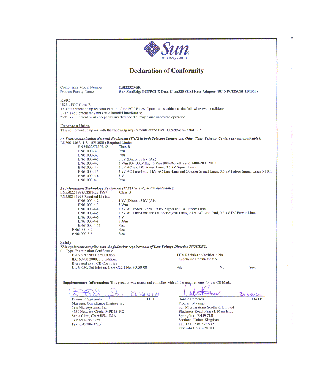
Declaration of Conformity
Compliance Model Number: LSI22320-SR
Product Family Name: Sun StorEdge PCI/PCI-X Dual Ultra320 SCSI Host Adapter (SGXPCI2SCSILM320-Z)
EMC
USA - FCC Class B
This equipment complies with Part 15 of the FCC Rules. Operation is subject to the following two conditions:
1. This equipment may not cause harmful interference.
2. This equipment must accept any interference that may cause undesired operation.
European Union
This equipment complies with the following requirements of the EMC Directive 89/336/EEC:
As Telecommunication Network Equipment (TNE) in Both Telecom Centers and Other Than Telecom Centers per (as applicable):
EN300-386 V.1.3.2 (2003-05) Required Limits:
EN 55022:1994 +A1:1995 +A2:1997 Class B
EN 61000-3-2:2000 Pass
EN 61000-3-3:1995 +A1:2000 Pass
IEC 61000-4-2 6 kV (Direct), 8 kV (Air)
IEC 61000-4-3 3 V/m 80-1000MHz, 10 V/m 800-960 MHz, and 1400-2000 MHz
IEC 61000-4-4 1 kV AC and DC Power Lines, 0.5 kV Signal Lines
IEC 61000-4-5 2 kV AC Line-Gnd, 1 kV AC Line-Line and Outdoor Signal Lines, 0.5 kV Indoor signal Lines > 10m
IEC 61000-4-6 3 V
IEC 61000-4-11 Pass
As Information Technology Equipment (ITE) Class B per (as applicable):
EN55022:1994 +A1 1995 +A2:1997 Class B
EN 61000-3-2:2000 Pass
EN 61000-3-3:1995 +A1:2000 Pass
EN 55024:1998 +A1: 2001 +A2:2003 Required Limits:
IEC 61000-4-2 4 kV (Direct), 8 kV (Air)
IEC 61000-4-3 3 V/m
IEC 61000-4-4 1 kV AC Power Lines, 0.5 kV Signal and DC Power Lines
IEC 61000-4-5 1 kV AC Line-Line and Outdoor Signal Lines, 2 kV AC Line-Gnd, 0.5 kV DC Power Lines
IEC 61000-4-6 3 V
IEC 61000-4-8 1 A/m
IEC 61000-4-11 Pass
Safety: This equipment complies with the following requirements of the Low Voltage Directive 73/23/EEC:
EC Type Examination Certificates:
EN60950-1:2001, First Edition TÜV Rheinland Certificate No.
IEC 60950-1:2001, 1st Edition CB Scheme Certificate No.
Evaluated to all CB Countries
UL 60950:2000, 3rd Edition, CSA C22.2 No. 60950-00 File:
Supplementary Information: This equipment was tested and complies with all the requirements for the CE Mark.
This equipment complies with the Restriction of Hazardous Substances (RoHS) directive
2002/95/EC.
/S/ /S/
Dennis P. Symanski DATE
Worldwide Compliance Office
Sun Microsystems, Inc.
4150 Network Circle, MPK15-102
Santa Clara, CA 95054, U.S.A.
Tel: 650-786-3255
Fax: 650-786-3723
Donald Cameron DATE
Program Manager/Quality Systems
Sun Microsystems Scotland, Limited
Blackness Road, Phase I, Main Bldg.
Springfield, EH49 7LR
Scotland, United Kingdom
Tel: +44 1 506 672 539
Fax: +44 1 506 670 011
24 Sun StorEdge PCI/PCI-X Dual Ultra320 SCSI Host Adapter Installation Guide • January 2007
Page 35
Appendix C Declaration of Conformity 25
Page 36

Regulatory Compliance Statements
Your Sun product is marked to indicate its compliance class:
• Federal Communications Commission (FCC) — USA
• Department of Communications (DOC) — Canada
• Voluntary Control Council for Interference (VCCI) — Japan
Please read the appropriate section that corresponds to the marking on your Sun product before attempting to install the
product.
FCC ClassA Notice
This device complies with Part 15 of the FCC Rules. Operation is subject to the following two conditions:
1. This device may not cause harmful interference.
2. This device must accept any interference received, including interference that may cause undesired operation.
Note: This equipment hasbeen tested and found to comply with the limits for a Class A digital device, pursuant to Part 15of
the FCC Rules. These limits are designed to provide reasonable protection against harmful interference when the equipment
is operated in a commercial environment. This equipment generates, uses and can radiate radio frequency energy and, if not
installed and used in accordance with the instruction manual, may cause harmful interference to radio communications.
Operation ofthis equipment ina residential area is likelyto cause harmfulinterference inwhich case theuser will be required
to correct the interference at his own expense.
Shielded Cables: Connections between the workstation and peripherals must be made using shielded cables in order to
maintain compliance with FCC radio frequency emission limits. Networking connections can be made using unshielded
twisted-pair (UTP) cables.
Modifications: Any modifications made to this device that are not approved by Sun Microsystems, Inc. may void the
authority granted to the user by the FCC to operate this equipment.
FCC ClassB Notice
This device complies with Part 15 of the FCC Rules. Operation is subject to the following two conditions:
1. This device may not cause harmful interference.
2. This device must accept any interference received, including interference that may cause undesired operation.
Note: This equipment has beentested and found to comply with the limits for a Class B digital device, pursuant to Part 15 of
the FCC Rules. These limits are designed to provide reasonable protection against harmful interference in a residential
installation. This equipment generates, uses and can radiate radio frequency energy and, if not installed and used in
accordance with the instructions, may cause harmful interference to radio communications. However, there is no guarantee
that interference will not occur in a particular installation. If this equipment does cause harmful interference to radio or
television reception, which can be determined by turning the equipment off and on, the user is encouraged to try to correct
the interference by one or more of the following measures:
• Reorient or relocate the receiving antenna.
• Increase the separation between the equipment and receiver.
• Connect the equipment into an outlet on a circuit different from that to which the receiver is connected.
• Consult the dealer or an experienced radio/television technician for help.
Shielded Cables: Connections between the workstation and peripherals must be made using shielded cables in order to
maintain compliance with FCC radio frequency emission limits. Networking connections can be made using unshielded
twisted pair (UTP) cables.
Modifications: Any modifications made to this device that are not approved by Sun Microsystems, Inc. may void the
authority granted to the user by the FCC to operate this equipment.
26 Sun StorEdge PCI/PCI-X Dual Ultra320 SCSI Host Adapter Installation Guide • January 2007
Page 37
Safety Agency Compliance
Statements
Read this section before beginning any procedure. The
following text provides safety precautions to follow when
installing a Sun Microsystems product.
Safety Precautions
For your protection, observe the following safety
precautions when setting up your equipment:
■ Follow all cautions and instructions marked on the
equipment.
■ Ensure that the voltage and frequency of your power
source match the voltage and frequency inscribed on
the equipment’s electrical rating label.
■ Never push objects of any kind through openings in
the equipment. Dangerous voltages may be present.
Conductive foreign objects could produce a short
circuit that could cause fire, electric shock, or damage
to your equipment.
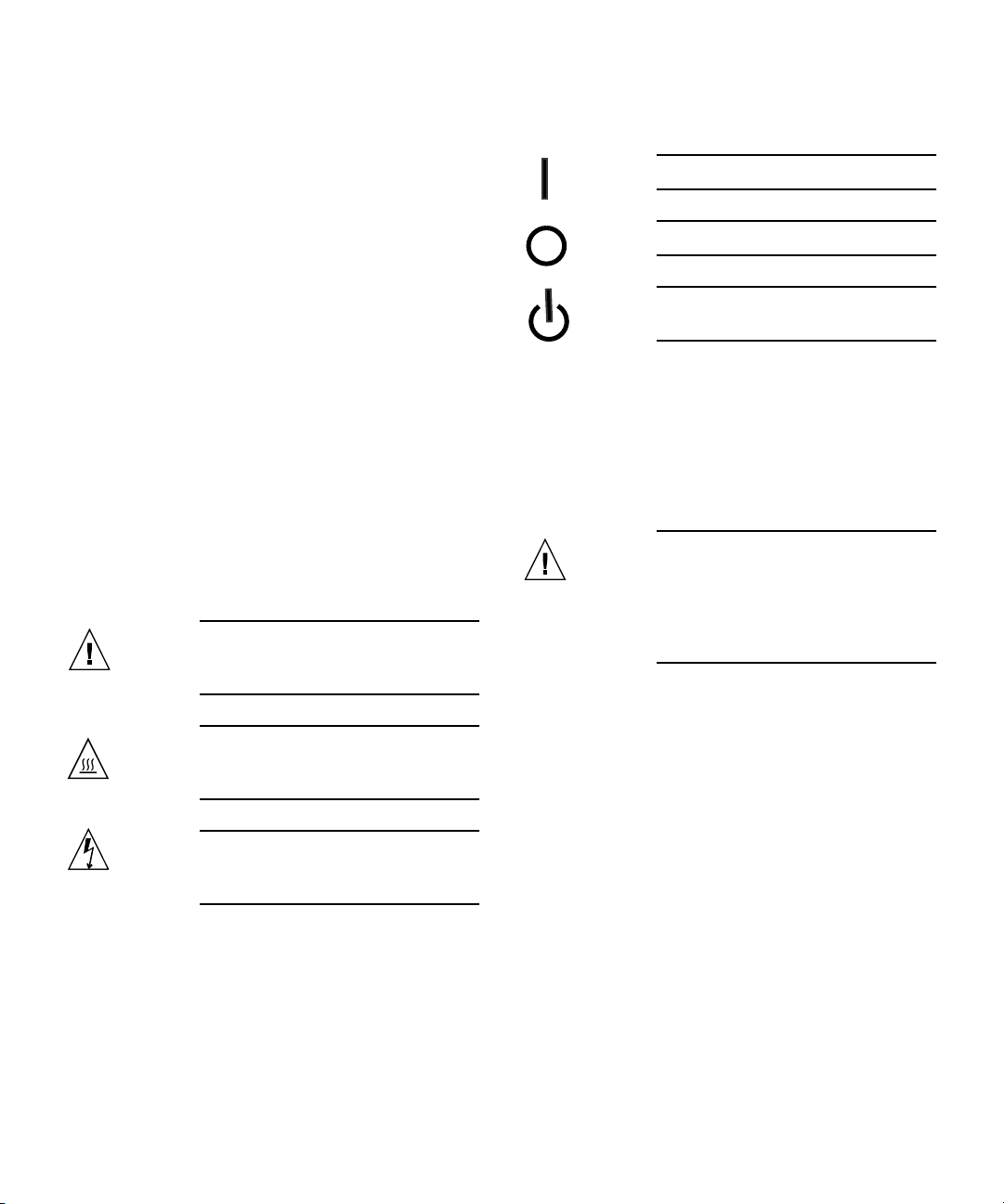
Symbols
The following symbols may appear in this book:
Caution – There is a risk of personal injury
and equipment damage. Follow the
instructions.
Depending on the type of power switch your device has,
one of the following symbols may be used:
On – Applies AC power to the system.
Off – Removes AC power from the system.
Standby – The On/Standby switch is in the
standby position.
Modifications to Equipment
Do not make mechanical or electrical modifications to the
equipment. Sun Microsystems is not responsible for
regulatory compliance of a modified Sun product.
Placement of a Sun Product
Caution – Do not block or cover the
openings of your Sun product. Never place a
Sun product near a radiator or heat register.
Failure to follow these guidelines can cause
overheating and affect the reliability of your
Sun product.
Caution – Hot surface. Avoid contact.
Surfaces are hot and may cause personal
injury if touched.
Caution – Hazardous voltages are present.
To reduce the risk of electric shock and danger
to personal health, follow the instructions.
Appendix C Declaration of Conformity, Regulatory, and Safety Information 27
Noise Level
In compliance with the requirements defined in DIN 45635
Part 1000, the workplace-dependent noise level of this
product is less than 70 db(A).
Page 38
SELV Compliance
Safety status of I/O connections comply to SELV
requirements.
Power Cord Connection
Caution – Sun products are designed to
work with power systems having a grounded
neutral (grounded return for DC-powered
products). To reduce the risk of electric shock,
do not plug Sun products into any other type
of power system. Contact your facilities
manager or a qualified electrician if you are
not sure what type of power is supplied to
your building.
Caution – Not all power cords have the
same current ratings. Do not use the power
cord provided with your equipment for any
other products or use. Household extension
cords do not have overload protection and are
not meant for use with computer systems. Do
not use household extension cords with your
Sun product.
The followingcaution applies only to deviceswith multiple
power cords:
Caution – For products with multiple
power cords, all power cords must be
disconnected to completely remove power
from the system.
Battery Warning
Caution – There is danger of explosion if
batteries are mishandled or incorrectly
replaced. On systems with replaceable
batteries, replace only with the same
manufacturer and type or equivalent type
recommended by the manufacturer per the
instructions provided in the product service
manual. Do not disassemble batteries or
attempt to recharge them outside the system.
Do not dispose of batteries in fire. Dispose of
batteries properly in accordance with the
manufacturer’s instructions and local
regulations. Note that on Sun CPU boards,
there is a lithium battery molded into the realtime clock. These batteries are not customer
replaceable parts.
System Unit Cover
You must remove the cover of your Sun computer system
unit to add cards, memory, or internal storage devices. Be
sure toreplace the cover before powering on yourcomputer
system.
The following caution applies only to devices with a
Standby power switch:
Caution – The power switch of this product
functions as a standby type device only. The
power cord serves as the primary disconnect
device for the system. Be sure to plug the
power cord into a grounded power outlet that
is nearby the system and is readily accessible.
Do not connect the power cord when the
power supply has been removed from the
system chassis.
28 Sun StorEdge PCI/PCI-X Dual Ultra320 SCSI Host Adapter Installation Guide • January 2007
Caution – Do not operate Sun products
without the cover in place. Failure to take this
precaution may result in personal injury and
system damage.
Page 39

Rack System Warning
The following warnings apply to Racks and Rack Mounted
systems.
CD and DVD Devices
The following caution applies to CD, DVD, and other
optical devices.
Caution – For safety, equipment should
always be loaded from the bottom up. That is,
install the equipment that will be mounted in
the lowest part of the rack first, then the next
higher systems, etc.
Caution – To prevent the rack from tipping
during equipment installation, the anti-tilt bar
on the rack must be deployed.
Caution – To prevent extreme operating
temperature within the rack insure that the
maximum temperature does not exceed the
product’s ambient rated temperatures.
Caution – To prevent extreme operating
temperatures due to reduced airflow
consideration should be made to the amount
of air flow that is required for a safe operation
of the equipment.
Laser Compliance Notice
Sun products that use laser technology comply withClass 1
laser requirements.
Caution – Use of controls, adjustments, or
the performance of procedures other than
those specified herein may result in hazardous
radiation exposure.
Conformité aux normes de sécurité
Veuillez lire attentivement cette section avant de
commencer. Ce texte traite des mesures de sécurité qu’il
convient de prendre pour l’installation d’un produit Sun
Microsystems.
Mesures de sécurité
Pour votre sécurité, nous vous recommandons de suivre
scrupuleusement lesmesures de sécuritéci-dessous lorsque
vous installez votre matériel:
■ Suivez tous les avertissements et toutes les
instructions inscrites sur le matériel.
■ Assurez-vous que la tension et la fréquence de votre
source d'alimentation correspondent à la tension et à
la fréquence indiquées sur l'étiquette de la tension
électrique nominale du matériel
■ N'introduisez jamais d'objets quels qu'ils soient dans
les ouvertures de l'équipement. Vous pourriez vous
trouver en présence de hautes tensions dangereuses.
Tout objet étranger conducteur risque de produire un
court-circuit pouvant présenter un risque d'incendie
ou de décharge électrique, ou susceptible
d'endommager le matériel.
Class 1 Laser Product
Luokan 1 Laserlaite
Klasse 1 Laser Apparat
Laser Klasse 1
Symboles
Vous trouverez ci-dessous la signification des différents
symboles utilisés:
Attention – Vous risquez d'endommager le
matériel ou de vous blesser. Veuillez suivre les
instructions.
Attention – Surfaces brûlantes. Evitez tout
contact. Les surfaces sont brûlantes. Vous
risquez de vous blesser si vous les touchez.
Appendix C Declaration of Conformity, Regulatory, and Safety Information 29
Page 40
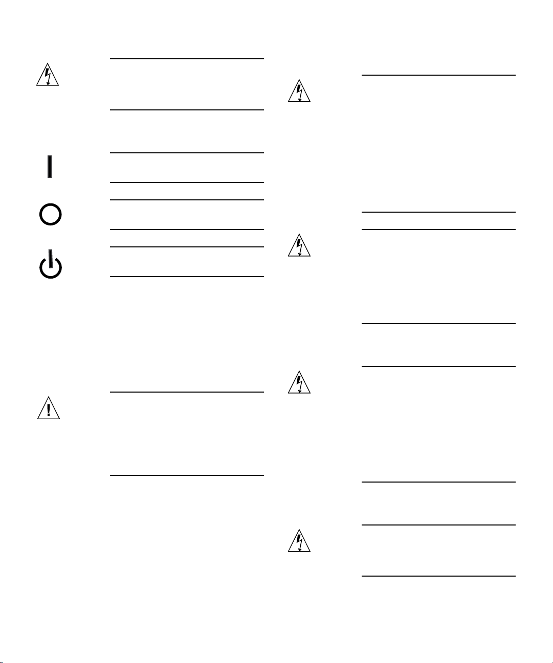
Attention – Tensions dangereuses. Pour
réduire les risques de décharge électrique et
de danger physique, observez les consignes
indiquées.
Selon le type d'interrupteur marche/arrêt dont votre
appareil est équipé, l'un des symboles suivants sera utilisé:
Marche – Met le système sous tension
alternative.
Arret – Met le système hors tension
alternative.
Veilleuse – L'interrupteur Marche/Veille
est sur la position de veille.
Modification du matériel
N'apportez aucune modification mécanique ou électrique
au matériel. Sun Microsystems décline toute responsabilité
quant à la non-conformité éventuelle d'un produit Sun
modifié.
Connexion du cordon d’alimentation
Attention – Les produits Sun sont conçus
pour fonctionner avec des systèmes
d'alimentation équipés d'un conducteur
neutre relié à la terre (conducteur neutre pour
produits alimentés en CC). Pour réduire les
risques de décharge électrique, ne branchez
jamais les produits Sun sur une source
d'alimentation d'un autre type. Contactez le
gérant de votre bâtiment ou un électricien
agréé si vous avez le moindre doute quant au
type d'alimentation fourni dans votre
bâtiment.
Attention – Tous les cordons d'alimentation
ne présentent pas les mêmes caractéristiques
électriques. Les cordons d'alimentation à
usage domestique ne sont pas protégés contre
les surtensions et ne sont pas conçus pour être
utilisés avec des ordinateurs. N'utilisez jamais
de cordon d'alimentation à usage domestique
avec les produits Sun.
L'avertissement suivant s'applique uniquement aux
systèmes équipés d'un interrupteur Veille:
Positionnement d’un produit Sun
Attention – Evitez d'obstruer ou de
recouvrir les orifices de votre produit Sun.
N'installez jamais un produit Sun près d'un
radiateur ou d'une source de chaleur. Si vous
ne respectez pas ces consignes, votre produit
Sun risque de surchauffer et son
fonctionnement en sera altéré.
Niveau de pression acoustique
Le niveau de pression acoustique du lieu de travail définie
par lanorme DIN 45 635 Part 1000 doitêtre au maximum de
70 db(A).
L'avertissement suivant s'applique uniquement aux
systèmes équipés de plusieurs cordons d'alimentation:
Conformité SELV
Le niveau de sécurité des connexions E/S est conforme aux
normes SELV.
30 Sun StorEdge PCI/PCI-X Dual Ultra320 SCSI Host Adapter Installation Guide • January 2007
Attention – L'interrupteur d'alimentation
de ce produit fonctionne uniquement comme
un dispositif de mise en veille. Le cordon
d'alimentation constitue le moyen principal de
déconnexion de l'alimentation pour le
système. Assurez-vous de le brancher dans
une prise d'alimentation mise à la terre près
du système et facile d'accès. Ne le branchez
pas lorsque l'alimentation électrique ne se
trouve pas dans le châssis du système.
Attention – Pour mettre un système équipé
de plusieurs cordons d'alimentation hors
tension, il est nécessaire de débrancher tous
les cordons d'alimentation.
Page 41

Mise en garde relative aux batteries
Attention – Les batteries risquent
d’exploser en cas de manipulation maladroite
ou de remplacement incorrect. Pour les
systèmes dont les batteries sont remplaçables,
effectuez les remplacements uniquement selon
le modèle du fabricant ou un modèle
équivalent recommandé par le fabricant,
conformément aux instructions fournies dans
le manuel de service du système. N’essayez en
aucun cas de démonter les batteries, ni de les
recharger hors du système. Ne les jetez pas au
feu. Mettez-les au rebut selon les instructions
du fabricant et conformément à la législation
locale en vigueur. Notez que sur les cartes
processeur de Sun, une batterie au lithium a
été moulée dans l'horloge temps réel. Les
batteries ne sont pas des pièces remplaçables
par le client.
Attention – Afin d'éviter que le rack ne
penche pendant l'installation du matériel, tirez
la barre anti-basculement du rack.
Attention – Pour éviter des températures de
fonctionnement extrêmes dans le rack,
assurez-vous que la température maximale ne
dépasse pas la fourchette de températures
ambiantes du produit déterminée par le
fabricant.
Attention – Afin d'empêcher des
températures de fonctionnement extrêmes
provoquées par une aération insuffisante,
assurez-vous de fournir une aération
appropriée pour un fonctionnement du
matériel en toute sécurité
Couvercle de l'unité
Pour ajouterdes cartes,de la mémoire ou des périphériques
de stockage internes, vous devez retirer le couvercle de
votre système Sun. Remettez le couvercle supérieur en
place avant de mettre votre système sous tension.
Attention – Ne mettez jamais des produits
Sun sous tension si leur couvercle supérieur
n'est pas mis en place. Si vous ne prenez pas
ces précautions, vous risquez de vous blesser
ou d'endommager le système.
Mise en garde relative au système en rack
La mise en garde suivante s'applique aux racks et aux
systèmes montés en rack.
Attention – Pour des raisons de sécurité, le
matériel doit toujours être chargé du bas vers
le haut. En d'autres termes, vous devez
installer, en premier, le matériel qui doit se
trouver dans la partie la plus inférieure du
rack, puis installer le matériel sur le niveau
suivant, etc.
Avis de conformité des appareils laser
Les produitsSun quifont appelaux technologieslasers sont
conformes aux normes de la classe 1 en la matière.
Class 1 Laser Product
Luokan 1 Laserlaite
Klasse 1 Laser Apparat
Laser Klasse 1
Périphériques CD et DVD
L'avertissement suivant s'applique aux périphériques CD,
DVD et autres périphériques optiques:
Attention – L'utilisation de contrôles et de
réglages ou l'application de procédures autres
que ceux spécifiés dans le présent document
peuvent entraîner une exposition à des
radiations dangereuses.
Appendix C Declaration of Conformity, Regulatory, and Safety Information 31
Page 42

Einhaltung sicherheitsbehördlicher
Vorschriften
Lesen Sie vor dem Ausführen von Arbeiten diesen
Abschnitt. Im folgenden Text werden Sicherheitsvorkehrungen beschrieben, die Sie bei der Installation eines
Sun Microsystems-Produkts beachten müssen.
Sicherheitsvorkehrungen
Treffen Sie zu Ihrem eigenen Schutzbei der Installation des
Geräts die folgenden Sicherheitsvorkehrungen:
■ Beachten Sie alle auf den Geräten angebrachten
Warnhinweise und Anweisungen.
■ Stellen Sie sicher, dass Spannung und Frequenz der
Stromversorgung den Nennleistungen auf dem am
Gerät angebrachten Etikett entsprechen.
■ Führen Sie niemals Fremdobjekte in die Öffnungen
am Gerät ein. Es können gefährliche Spannungen
anliegen. Leitfähige Fremdobjekte können einen
Kurzschluss verursachen, der einen Brand, Stromschlag oder Geräteschaden herbeiführen kann.
Je nach Netzschaltertyp an Ihrem Gerät kann eines der
folgenden Symbole verwendet werden:
Ein – Versorgt das System mit Wechselstrom.
Aus– Unterbricht die Wechselstromzufuhr
zum Gerät.
Wartezustand – Der Ein-/Standby-Netz-
schalter befindet sich in der Standby-Position.
Modifikationen des Geräts
Nehmen Sie keine elektrischen oder mechanischen
Gerätemodifikationen vor. Sun Microsystems ist für die
Einhaltung der Sicherheitsvorschriften von modifizierten
Sun-Produkten nicht haftbar.
Symbole
Die Symbole in diesem Handbuch haben folgende
Bedeutung:
Achtung – Gefahr von Verletzung und
Geräteschaden. Befolgen Sie die Anweisungen.
Achtung – Heiße Oberfläche. Nicht
berühren, da Verletzungsgefahr durch heiße
Oberfläche besteht.
Achtung – Gefährliche Spannungen.
Befolgen Sie die Anweisungen, um
Stromschläge und Verletzungen zu vermeiden.
Aufstellung von Sun-Geräten
Achtung – Geräteöffnungen Ihres Sun-
Produkts dürfen nicht blockiert oder
abgedeckt werden. Sun-Geräte sollten niemals
in der Nähe von Heizkörpern oder Heißluftklappen aufgestellt werden. Die Nichtbeachtung dieser Richtlinien kann Überhitzung
verursachen und die Zuverlässigkeit Ihres
Sun-Geräts beeinträchtigen.
Lautstärke
Gemäß denin DIN 45 635 Teil1000 definiertenVorschriften
beträgt diearbeitsplatzbedingte Lautstärke dieses Produkts
weniger als 70 dB(A).
SELV-Konformität
Der Sicherheitsstatus der E/A-Verbindungen entspricht
den SELV-Anforderungen.
32 Sun StorEdge PCI/PCI-X Dual Ultra320 SCSI Host Adapter Installation Guide • January 2007
Page 43

Anschluss des Netzkabels
Warnung bezüglich Batterien
Achtung – Sun-Geräte sind für
Stromversorgungssysteme mit einem
geerdeten neutralen Leiter (geerdeter
Rückleiter bei gleichstrombetriebenen
Geräten) ausgelegt. Um die Gefahr von
Stromschlägen zu vermeiden, schließen Sie
das Gerät niemals an andere Stromversorgungssysteme an. Wenden Sie sich an den
zuständigen Gebäudeverwalter oder an einen
qualifizierten Elektriker, wenn Sie nicht sicher
wissen, an welche Art von Stromversorgungssystem Ihr Gebäude angeschlossen ist.
Achtung – Nicht alle Netzkabel verfügen
über die gleichen Nennwerte. Herkömmliche,
im Haushalt verwendete Verlängerungskabel
besitzen keinen Überlastschutz und sind
daher für Computersysteme nicht geeignet.
Verwenden Sie bei Ihrem Sun-Produkt keine
Haushalts-Verlängerungskabel.
Die folgende Warnung gilt nur für Geräte mit StandbyNetzschalter:
Achtung – Beim Netzschalter dieses Geräts
handelt es sich nur um einen Ein/StandbySchalter. Zum völligen Abtrennen des Systems
von der Stromversorgung dient hauptsächlich
das Netzkabel. Stellen Sie sicher, dass das
Netzkabel an eine frei zugängliche geerdete
Steckdose in der Nähe des Systems angeschlossen ist. Schließen Sie das Stromkabel
nicht an, wenn die Stromversorgung vom
Systemchassis entfernt wurde.
Die folgende Warnung gilt nur für Geräte mit mehreren
Netzkabeln:
Achtung – Bei Produkten mit mehreren
Netz-kabeln müssen alle Netzkabel abgetrennt
wer-den, um das System völlig von der
Stromver-sorgung zu trennen.
Achtung – Bei unsachgemäßer
Handhabung oder nicht fachgerechtem
Austausch der Batterien besteht
Explosionsgefahr. Verwen-den Sie bei
Systemen mit austauschbaren Batterien
ausschließlich Ersatzbatterien desselben Typs
und Herstellers bzw. einen entsprechenden,
vom Hersteller gemäß den Anweisungen im
Service-Handbuch des Produkts empfohlenen
Batterietyp. Versuchen Sie nicht, die Batterien
auszubauen oder außerhalb des Systems
wiederaufzuladen. Werfen Sie die Batterien
nicht ins Feuer. Entsorgen Sie die Batterien
entsprechend den Anweisungen des
Herstellers und den vor Ort geltenden
Vorschriften. CPU-Karten von Sun verfügen
über eine Echtzeituhr mit integrier-ter
Lithiumbatterie. Diese Batterie darf nur von
einem qualifizierten Servicetechniker ausgewechselt werden.
Gehäuseabdeckung
Sie müssen die Abdeckung Ihres Sun-Computersystems
entfernen, um Karten, Speicher oderinterne Speichergeräte
hinzuzufügen. Bringen Sie vor dem Einschalten des
Systems die Gehäuseabdeckung wieder an.
Achtung – Nehmen Sie Sun-Geräte nicht
ohne Abdeckung in Betrieb. Die
Nichtbeachtung dieses Warnhinweises kann
Verletzungen oder Geräteschaden zur Folge
haben.
Warnungen bezüglich in Racks eingebauter
Systeme
Die folgenden Warnungen gelten für Racks und in Racks
eingebaute Systeme:
Achtung – Aus Sicherheitsgründen sollten
sämtliche Geräte von unten nach oben in
Racks eingebaut werden. Installieren Sie also
zuerst die Geräte, die an der untersten
Appendix C Declaration of Conformity, Regulatory, and Safety Information 33
Page 44

Position im Rack eingebaut werden, gefolgt
von den Systemen, die an nächsthöherer Stelle
eingebaut werden, usw.
Normativas de seguridad
Lea esta sección antes de realizar cualquier operación. En
ella seexplican las medidasde seguridad que debe tomaral
instalar un producto de Sun Microsystems.
Achtung – Verwenden Sie beim Einbau den
Kippschutz am Rack, um ein Umkippen zu
vermeiden.
Achtung – Um extreme
Betriebstemperaturen im Rack zu vermeiden,
stellen Sie sicher, dass die Maximaltemperatur
die Nennleistung der Umgebungstemperatur
für das Produkt nicht überschreitet
Achtung – Um extreme
Betriebstemperaturen durch verringerte
Luftzirkulation zu vermei-den, sollte die für
den sicheren Betrieb des Geräts erforderliche
Luftzirkulation eingesetzt werden.
Hinweis zur Laser-Konformität
Sun-Produkte, die die Laser-Technologie verwenden,
entsprechen den Laser-Anforderungen der Klasse 1.
Class 1 Laser Product
Luokan 1 Laserlaite
Klasse 1 Laser Apparat
Laser Klasse 1
Medidas de seguridad
Para su protección, tome las medidas de seguridad
siguientes durante la instalación del equipo:
■ Siga todos los avisos e instrucciones indicados en el
equipo.
■ Asegúrese de que el voltaje y frecuencia de la fuente
de alimentación coincidan con el voltaje y frecuencia
indicados en la etiqueta de clasificación eléctrica del
equipo.
■ No introduzca objetos de ningún tipo por las rejillas
del equipo, ya que puede quedar expuesto a voltajes
peligrosos. Los objetos conductores extraños pueden
producir cortocircuitos y, en consecuencia, incendios,
descargas eléctricas o daños en el equipo.
Símbolos
En este documento aparecen los siguientes símbolos:
Precaución – Existe el riesgo de que se
produzcan lesiones personales y daños en el
equipo. Siga las instrucciones.
Precaución – Superficie caliente. Evite
todo contacto. Las superficies están calientes y
pueden causar lesiones personales si se tocan.
Precaución – Voltaje peligroso. Para
reducir el riesgo de descargas eléctricas y
lesiones personales, siga las instrucciones.
CD- und DVD-Geräte
Die folgende Warnung gilt für CD-, DVD- und andere
optische Geräte:
Achtung – Die hier nicht aufgeführte
Verwendung von Steuerelementen,
Anpassungen oder Ausführung von
Vorgängen kann eine gefährliche
Strahlenbelastung verursachen.
34 Sun StorEdge PCI/PCI-X Dual Ultra320 SCSI Host Adapter Installation Guide • January 2007
Page 45

En función del tipo de interruptor de alimentación del que
disponga el dispositivo, se utilizará uno de los símbolos
siguientes:
Encendido – Suministra alimentación de
CA al sistema.
Apagado – Corta la alimentación de CA del
sistema.
Espera – El interruptor de
encendido/espera está en la posición de
espera.
Conexión del cable de alimentación
Precaución – Los productos Sun se han
diseñado para funcionar con sistemas de
alimentación que cuenten con un conductor
neutro a tierra (con conexión a tierra de
regreso para los productos con alimentación
de CC). Para reducir el riesgo de descargas
eléctricas, no conecte ningún producto Sun a
otro tipo de sistema de alimentación. Póngase
en contacto con el encargado de las
instalaciones de su empresa o con un
electricista cualificado en caso de que no esté
seguro del tipo de alimentación del que se
dispone en el edificio.
Modificaciones en el equipo
No realicemodificaciones de tipo mecánico ni eléctrico en el
equipo. Sun Microsystems no se hace responsable del
cumplimiento de normativas en caso de que un producto
Sun se haya modificado.
Colocación de un producto Sun
Precaución – No obstruya ni tape las
rejillas del producto Sun. Nunca coloque un
producto Sun cerca de radiadores ni fuentes
de calor. Si no sigue estas indicaciones, el
producto Sun podría sobrecalentarse y la
fiabilidad de su funcionamiento se vería
afectada.
Nivel de ruido
De conformidad con los requisitos establecidos en el
apartado 1000 de la norma DIN 45635, el nivel de ruido en
el lugarde trabajoproducido poreste productoes menorde
70 db(A).
Cumplimiento de la normativa para
instalaciones SELV
Las condiciones de seguridad de las conexiones de entrada
y salidacumplen losrequisitos para instalaciones SELV (del
inglés Safe Extra Low Voltage, voltaje bajo y seguro).
Precaución – No todos los cables de
alimentación tienen la misma clasificación
eléctrica. Los alargadores de uso doméstico no
cuentan con protección frente a sobrecargas y
no están diseñados para su utilización con
sistemas informáticos. No utilice alargadores
de uso doméstico con el producto Sun.
La siguiente medida solamente se aplica a aquellos
dispositivos que dispongan de un interruptor de
alimentación de espera:
Precaución – El interruptor de
alimentación de este producto funciona
solamente como un dispositivo de espera. El
cable de alimentación hace las veces de
dispositivo de desconexión principal del
sistema. Asegúrese de que conecta el cable de
alimentación a una toma de tierra situada
cerca del sistema y de fácil acceso. No conecte
el cable de alimentación si la unidad de
alimentación no se encuentra en el bastidor
del sistema.
Appendix C Declaration of Conformity, Regulatory, and Safety Information 35
Page 46

La siguiente medida solamente se aplica a aquellos
dispositivos que dispongan de varios cables de
alimentación:
Advertencia sobre el sistema en bastidor
Las advertencias siguientes se aplican a los sistemas
montados en bastidor y a los propios bastidores.
Precaución – En los productos que
cuentan con varios cables de alimentación,
debe desconectar todos los cables de
alimentación para cortar por completo la
alimentación eléctrica del sistema.
Advertencia sobre las baterías
Precaución – Si las baterías no se
manipulan o reemplazan correctamente, se
corre el riesgo de que estallen. En los sistemas
que cuentan con baterías reemplazables,
reemplácelas sólo con baterías del mismo
fabricante y el mismo tipo, o un tipo
equivalente recomendado por el fabricante, de
acuerdo con las instrucciones descritas en el
manual de servicio del producto. No
desmonte las baterías ni intente recargarlas
fuera del sistema. No intente deshacerse de las
baterías echándolas al fuego. Deshágase de las
baterías correctamente de acuerdo con las
instrucciones del fabricante y las normas
locales. Tenga en cuenta que en las placas CPU
de Sun, hay una batería de litio incorporada
en el reloj en tiempo real. Los usuarios no
deben reemplazar este tipo de baterías.
Precaución – Por seguridad, siempre
deben montarse los equipos de abajo arriba. A
saber, primero debe instalarse el equipo que se
situará en el bastidor inferior; a continuación,
el que se situará en el siguiente nivel, etc.
Precaución – Para evitar que el bastidor se
vuelque durante la instalación del equipo,
debe extenderse la barra antivolcado del
bastidor.
Precaución – Para evitar que se alcance
una temperatura de funcionamiento extrema
en el bastidor, asegúrese de que la
temperatura máxima no sea superior a la
temperatura ambiente establecida como
adecuada para el producto.
Precaución – Para evitar que se alcance
una temperatura de funcionamiento extrema
debido a una circulación de aire reducida,
debe considerarse la magnitud de la
circulación de aire requerida para que el
equipo funcione de forma segura.
Cubierta de la unidad del sistema
Debe extraer la cubierta de la unidad del sistema
informático Sun para instalar tarjetas, memoria o
dispositivos de almacenamiento internos. Vuelva a colocar
la cubierta antes de encender el sistema informático.
Precaución – No ponga en funcionamiento
los productos Sun que no tengan colocada la
cubierta. De lo contrario, puede sufrir lesiones
personales y ocasionar daños en el sistema.
36 Sun StorEdge PCI/PCI-X Dual Ultra320 SCSI Host Adapter Installation Guide • January 2007
Aviso de cumplimiento de la normativa para
la utilización de láser
Los productos Sunque utilizantecnología lásercumplen los
requisitos establecidos para los productos láser de clase 1.
Class 1 Laser Product
Luokan 1 Laserlaite
Klasse 1 Laser Apparat
Laser Klasse 1
Page 47

Dispositivos de CD y DVD
La siguiente medida se aplica a los dispositivos de CD y
DVD, así como a otros dispositivos ópticos:
Precaución – La utilización de controles,
ajustes o procedimientos distintos a los aquí
especificados puede dar lugar a niveles de
radiación peligrosos.
Nordic Lithium Battery Cautions
Norge
Advarsel – Litiumbatteri —
Eksplosjonsfare. Ved utskifting benyttes kun
batteri som anbefalt av apparatfabrikanten.
Brukt batteri returneres apparatleverandøren.
Sverige
Varning – Explosionsfara vid felaktigt
batteribyte. Använd samma batterityp eller en
ekvivalent typ som rekommenderas av
apparattillverkaren. Kassera använt batteri
enligt fabrikantens instruktion.
Danmark
Suomi
Advarsel! – Litiumbatteri —
Eksplosionsfare ved fejlagtig håndtering.
Udskiftning må kun ske med batteri af samme
fabrikat og type. Levér det brugte batteri
tilbage til leverandøren.
Varoitus – Paristo voi räjähtää, jos se on
virheellisesti asennettu. Vaihda paristo
ainoastaan laitevalmistajan suosittelemaan
tyyppiin. Hävitä käytetty paristo valmistajan
ohjeiden mukaisesti.
Appendix C Declaration of Conformity, Regulatory, and Safety Information 37
Page 48

38 Sun StorEdge PCI/PCI-X Dual Ultra320 SCSI Host Adapter Installation Guide • January 2007
 Loading...