

Page 1

Sun™ Storage J4200/J4400 Array
System Overview
Sun Microsystems, Inc.
www.sun.com
Part No. 820-3223-14
June 2009
Submit comments about this document at: http://www.sun.com/hwdocs/feedback
Page 2

Copyright 2009Sun Microsystems,Inc., 4150 Network Circle, SantaClara, California95054, U.S.A. All rights reserved.
Sun Microsystems, Inc.has intellectual property rights relating to technologythat isdescribed in this document. Inparticular, and without
limitation, theseintellectual propertyrights may include one ormore ofthe U.S. patents listed athttp://www.sun.com/patentsand one or
more additional patents orpending patent applications in theU.S. and in other countries.
This documentand the product to which it pertainsare distributedunder licenses restricting their use,copying, distribution,and
decompilation. Nopart of the product or of thisdocument may be reproduced in any formby anymeans without priorwritten authorizationof
Sun andits licensors, if any.
Third-party software, including fonttechnology, is copyrightedand licensed from Sun suppliers.
Parts ofthe productmay be derived from BerkeleyBSD systems,licensed from the University ofCalifornia. UNIXis a registered trademark in
the U.S.and in other countries, exclusivelylicensed throughX/Open Company, Ltd.
Sun, SunMicrosystems, theSun logo,Java, AnswerBook2, docs.sun.com, Sun Fire,Sun StoragEdge,Sun StorageTek, and Solaris are trademarks
or registered trademarks of SunMicrosystems, Inc.in the U.S.and inother countries.
All SPARC trademarksare usedunder license and are trademarksor registeredtrademarks ofSPARCInternational, Inc. in the U.S.and in other
countries. Products bearingSPARCtrademarks arebased upon an architecture developed by SunMicrosystems, Inc.
The OPENLOOK and Sun™ Graphical UserInterface wasdeveloped by SunMicrosystems, Inc.for its users and licensees.Sun acknowledges
the pioneeringefforts ofXerox inresearching anddeveloping the concept of visualor graphical user interfaces forthe computer industry.Sun
holds anon-exclusive license from Xeroxto the Xerox Graphical UserInterface, which license also coversSun’s licenseeswho implement OPEN
LOOK GUIsand otherwise comply with Sun’swritten licenseagreements.
U.S. GovernmentRights—Commercial use.Government users are subject tothe SunMicrosystems, Inc. standard license agreement and
applicable provisions ofthe FAR and itssupplements.
DOCUMENTATION IS PROVIDED “AS IS” AND ALL EXPRESS OR IMPLIED CONDITIONS, REPRESENTATIONS AND WARRANTIES,
INCLUDING ANYIMPLIED WARRANTY OF MERCHANTABILITY,FITNESS FOR A PARTICULAR PURPOSE ORNON-INFRINGEMENT,
ARE DISCLAIMED, EXCEPT TO THE EXTENT THAT SUCH DISCLAIMERS ARE HELD TO BE LEGALLY INVALID.
Copyright 2009Sun Microsystems,Inc., 4150 Network Circle, SantaClara, Californie95054, États-Unis. Tous droits réservés.
Sun Microsystems, Inc.possède les droits de propriété intellectuels relatifs à latechnologie décrite dans ce document.En particulier, et sans
limitation, cesdroits depropriété intellectuelspeuvent inclure un ou plusieursdes brevetsaméricains listés sur le site
http://www.sun.com/patents, un oules plusieurs brevets supplémentaires ainsi que lesdemandes debrevet en attente aux lesÉtats-Unis et
dans d’autres pays.
Ce documentet le produit auquel il se rapportesont protégéspar un copyright et distribuéssous licences, celles-ci en restreignent l’utilisation,
la copie,la distribution, et la décompilation.Aucune partiede ce produit ou documentne peut être reproduitesous aucune forme, par quelque
moyen quece soit, sans l’autorisation préalableet écritede Sun etde sesbailleurs de licence, s’il yen a.
Tout logiciel tiers,sa technologie relative aux polices de caractères,comprise, estprotégé par un copyright etlicencié par des fournisseurs de
Sun.
Des partiesde ce produit peuvent dériver des systèmesBerkeley BSD licenciés par l’Universitéde Californie. UNIX est unemarque déposée
aux États-Uniset dans d’autres pays, licenciée exclusivement parX/Open Company, Ltd.
Sun, SunMicrosystems, lelogo Sun, Java, AnswerBook2, docs.sun.com,Sun Fire,Sun StoragEdge, Sun StorageTek, et Solarissont des marques
de fabriqueou des marques déposées de Sun Microsystems,Inc. auxÉtats-Unis et dans d’autres pays.
Toutes les marquesSPARCsont utiliséessous licence et sont desmarques defabrique ou desmarques déposéesde SPARC International, Inc.
aux États-Uniset dans d’autres pays. Les produits portantles marquesSPARCsont basés sur une architecture développée parSun
Microsystems, Inc.
L’interfaceutilisateur graphiqueOPEN LOOK et Sun™ aété développée par Sun Microsystems,Inc. pourses utilisateurs et licenciés. Sun
reconnaît les efforts depionniers deXerox dans la rechercheet le développementdu conceptdes interfaces utilisateur visuelles ougraphiques
pour l’industrieinformatique. Sun détient une licensenon exclusivede Xerox sur l’interface utilisateurgraphique Xerox,cette licence couvrant
également leslicenciés de Sun implémentant lesinterfaces utilisateurgraphiques OPEN LOOKet seconforment en outre aux licencesécrites de
Sun.
LA DOCUMENTATION EST FOURNIE “EN L’ÉTAT” ET TOUTES AUTRES CONDITIONS, DÉCLARATIONS ET GARANTIES EXPRESSES
OU TACITES SONT FORMELLEMENT EXCLUES DANS LA LIMITE DE LA LOI APPLICABLE, Y COMPRIS NOTAMMENT TOUTE
GARANTIE IMPLICITE RELATIVE À LA QUALITÉ MARCHANDE, À L’APTITUDE À UNE UTILISATION PARTICULIÈRE OU À
L’ABSENCE DE CONTREFAÇON.
Please
Recycle
Page 3

Contents
Preface xiii
1. The Sun Storage J4200/J4400 Array 1
Hardware Overview 6
Front Access to the J4200/J4400 Array 6
Indicators on the Front of the Trays 8
Disk Drives 9
Rear-Access Tray Components 11
J4200/J4400 Array SIM Board 13
SIM Board Status Indicators 16
J4200/J4400 Array Power Supplies 17
J4200 Power Supply Status Indicators 19
J4400 Power Supply Status Indicators 21
J4200 Array Fan Modules 22
J4200 Fan Status Indicators 23
Customer-Replaceable Units 24
Management Software 24
Full Management Software 25
Remote Proxy 25
Command-Line Interface 25
iii
Page 4

2. Specifications 27
3. Understanding the Status Indicators 31
Introduction 31
Front Status Indicators 31
Disk Drives 33
Rear Status Indicators 34
J4200 SIM Board 34
SIM Board Status Indicators 37
J4200/J4400 Array Power Supplies 38
J4200 Power Supply Status Indicators 40
41
J4400 Power Supply Status Indicators 42
J4200 Array Fan Modules 42
J4200 Fan Status Indicators 43
44
4. Understanding the J4000 Family Event Log 45
5. SAS Multipathing 49
System Requirements 49
Required Operating Systems 50
Required Patch for Solaris 10 U6 With SATA Drives 50
Required Firmware and Drivers 50
Where to Get Drivers 51
Required HBA 51
Required CAM Versions for Multipathing 51
Configuration Examples 52
Multipathing With One Array and One Host 53
Multipathing With Two Arrays and Two Hosts 54
iv Sun Storage J4200/J4400 Array System Overview • June 2009
Page 5

Multipathing With Two Arrays and One Host 55
Enabling and Disabling Multipathing in the Solaris Operating System 56
Device Renaming 56
stmsboot Options 56
stmsboot Conditions 57
▼ To Enable Multipathing on all Multipath-Capable Controllers 58
▼ To Disable Multipathing on All Multipath-Capable Controllers 59
▼ To Enable Multipathing on Multipath-Capable Controller Ports 60
▼ To Disable Multipathing on Multipath-Capable Controller Ports 60
Configuring Multipathing on Selected Ports 60
Dynamic Discovery of SAS Devices 60
Enabling and Disabling Multipathing in the Windows Operating System 61
▼ To Enable Multipathing in Windows 2008 61
▼ To Discover Device Multipaths 64
▼ To Select a Load Balancing Policy 68
▼ To Disable Multipathing in Windows 2008 71
Enabling and Disabling Multipathing in the Linux Operating System 79
▼ To Enable Multipathing in Linux 79
▼ To Disable Multipathing in Linux 80
81
6. Troubleshooting and Hardware Replacement with Service Advisor 83
Service Advisor 83
Accessing Service Advisor Procedures 84
Basic Service Procedures 85
Taking ElectroStatic Discharge (ESD) Precautions 85
Reserving the Array for Maintenance 85
Releasing the Array After Maintenance 86
Troubleshooting 86
Contents v
Page 6

Problem Viewing the Number of Disks 86
LED Problems 87
Disk Swapping 87
Contacting Sun Technical Support 87
Glossary 89
Index 95
vi Sun Storage J4200/J4400 Array System Overview • June 2009
Page 7

Figures
FIGURE 1-1 J4200 Array Connected to a Data and Management Host 2
FIGURE 1-2 J4400 Array Connected to a Data and Management Host 3
FIGURE 1-3 J4200 Array Interconnected With Three Additional J4200s 4
FIGURE 1-4 J4400 Array Interconnected With Three Additional J4400s 5
FIGURE 1-5 J4200 Array Front Access Components 7
FIGURE 1-6 J4400 Array Front Access Components 7
FIGURE 1-7 Indicators on the Front of a Sample J4200 Array 8
FIGURE 1-8 Disk Drive 10
FIGURE 1-9 J4200 Array Rear-Access Components 11
FIGURE 1-10 J4400 Array Rear-Access Components 12
FIGURE 1-11 J4200 Array SIM Board Components and Status Indicator Descriptions 14
FIGURE 1-12 J4400 Array SIM Board Components and Status Indicator Descriptions 14
FIGURE 1-13 J4200 Array Power Supplies 17
FIGURE 1-14 J4400 Array Power Supplies 18
FIGURE 1-15 Individual J4200 Power Supply 18
FIGURE 1-16 Individual J4400 Power Supply 20
FIGURE 1-17 J4200 Array Fans 22
FIGURE 1-18 Individual J4200 Array Fan Module 23
FIGURE 3-1 Indicators on the Front of a Sample J4200 Array 32
FIGURE 3-2 Disk Drive 33
vii
Page 8

FIGURE 3-3 J4200 Array SIM Board Components and Status Indicator Descriptions 35
FIGURE 3-4 J4400 Array SIM Board Components and Status Indicator Descriptions 35
FIGURE 3-5 J4200 Array Power Supplies 38
FIGURE 3-6 J4400 Array Power Supplies 39
FIGURE 3-7 Individual J4200 Power Supply 39
FIGURE 3-8 Individual J4400 Power Supply 41
FIGURE 3-9 J4200 Array Fans 42
FIGURE 3-10 Individual J4200 Array Fan Module 43
FIGURE 5-1 Cabling Example for Multipathing With One Array and One Host 53
FIGURE 5-2 Cabling Example for Multipathing With Two Arrays and Two Hosts 54
FIGURE 5-3 Cabling Example for Multipathing With Two Arrays and One Host 55
FIGURE 5-4 Start Menu With Server Manager Selection 61
FIGURE 5-5 Server Manager Feature Display 62
FIGURE 5-6 Add Features Wizard Select Features Window 63
FIGURE 5-7 Confirm Installation Selections Window 63
FIGURE 5-8 Add Features Wizard Installation Results Window 64
FIGURE 5-9 MPIO Properties Window 65
FIGURE 5-10 MPIO Properties Window Device Multi-Paths Tab 66
FIGURE 5-11 Highlighted Device Hardware for Discovering Multipaths 67
FIGURE 5-12 Reboot Required Window 67
FIGURE 5-13 Device Manager Window 68
FIGURE 5-14 Menu to Modify Device Configuration 69
FIGURE 5-15 Disk Drive Properties Window 70
FIGURE 5-16 Round Robin Load Balance Policy Selected 71
FIGURE 5-17 Selecting Administrative Tools > MPIO From the Start Menu 72
FIGURE 5-18 MPIO Properties Window 73
FIGURE 5-19 Highlighting Device For Which to Disable Multipathing 74
FIGURE 5-20 Reboot Required Window 74
FIGURE 5-21 MPIO Properties Window With Device Removed From List 75
FIGURE 5-22 Server Manager Window With Features Panel Open 76
viii Sun Storage J4200/J4400 Array System Overview • June 2009
Page 9

FIGURE 5-23 Remove Features Wizard Window 77
FIGURE 5-24 Confirm Removal Selections Window 78
FIGURE 5-25 Removal Results Window 78
FIGURE 5-26 Restart Now Window 79
FIGURE 5-27 Removal Results Window 79
Figures ix
Page 10

x Sun Storage J4200/J4400 Array System Overview • June 2009
Page 11

Tables
TABLE 1-1 J4200/J4400 Front Panel Status Indicators 8
TABLE 1-2 J4200/J4400 Disk Drive Status Indicators 10
TABLE 1-3 SIM Board Components and Indicator Associations 15
TABLE 1-4 J4200/J4400 Array SIM Board Status Indicator Descriptions 16
TABLE 1-5 J4200 Array Power Supply Components 19
TABLE 1-6 J4200 Power Supply Status Indicators 19
TABLE 1-7 J4400 Array Power Supply Components 20
TABLE 1-8 J4400 Power Supply Status Indicators 21
TABLE 1-9 J4200 Fan Status Indicators 23
TABLE 2-1 Sun Storage J4200/J4400 Specifications 27
TABLE 3-1 J4200/J4400 Front Panel Status Indicators 32
TABLE 3-2 J4200/J4400 Disk Drive Status Indicators 33
TABLE 3-3 SIM Board Components and Indicator Associations 36
TABLE 3-4 J4200/J4400 Array SIM Board Status Indicator Descriptions 37
TABLE 3-5 J4200 Array Power Supply Components 40
TABLE 3-6 J4200 Power Supply Status Indicators 40
TABLE 3-7 J4400 Array Power Supply Components 41
TABLE 3-8 J4400 Power Supply Status Indicators 42
TABLE 3-9 J4200 Fan Status Indicators 44
TABLE 4-1 J4000 Family Event Log Listings 45
xi
Page 12

TABLE 5-1 Operating Systems That Support J4200/J4400 Multipathing 50
TABLE 5-2 Required Drivers By Operating System 51
TABLE 5-3 stmsboot Options 56
TABLE 5-4 Load Balance Policies 70
xii Sun Storage J4200/J4400 Array System Overview • June 2009
Page 13

Preface
The Sun™ Storage J4200/J4400 Array System Overview describes the components of
the Sun™ Storage J4200/J4400 arrays and how they work together with the Sun
StorageTek™ Common Array Manager (CAM) software. This document describes
the individual components and status indicators, specifications, the event log, and
troubleshooting information.
Refer to the Sun Storage J4200/J4400 Array Release Notes (820-3222-nn) for any latebreaking information.
Before You Read This Book
Before you begin to install the Sun Storage J4200/J4400, you must have already
prepared the site as described in these books:
■ Sun Storage J4200/J4400 Site Preparation Guide
xiii
Page 14

Related Documentation
Application Title Part Number
Regulatory and safety
information
Multilanguage safety
information
Site planning information Sun Storage J4200/J4400 Array Site
Installation at a glance Sun Storage J4200 Array Setup Poster 820-3221-nn
Installation at a glance Sun Storage J4400 Array Setup Poster 820-4691-nn
Complete details of the
hardware components, rail
and tray installation, and
cabling.
Late-breaking information
not included in the
information set
General operation and
troubleshooting
Disk drive replacement
procedures
SIM board replacement
procedures
Sun StorageTek Regulatory and Safety
Compliance Manual
Important Safety Information for Sun
Hardware Systems
Preparation Guide
Sun Storage J4200/J4400 Array Hardware
Installation Guide
Sun Storage J4200/J4400 Array Release
Notes
Sun Storage J4200/J4400 Array System
Overview
Sun Storage J4200/J4400 Array Disk Drive
Replacement Guide
Sun Storage J4200 Array SIM Board
Replacement Guide
96272, Revision A
816-7190-nn
820-3219-nn
820-3218-nn
820-3222-nn
820-3223-nn
820-3225-nn
820-3226-nn
SIM board replacement
procedures
Power supply replacement
procedures
Fan replacement procedures Sun Storage J4200 Array Fan Replacement
Power supply and fan
replacement procedures
Chassis replacement
procedures
Chassis replacement
procedures
Rail kit installation
procedures
xiv Sun Storage J4200/J4400 Array System Overview • June 2009
Sun Storage J4400 Array SIM Board
Replacement Guide
Sun Storage J4200 Array Power Supply
Replacement Guide
Guide
Sun Storage J4400 Array Power
Supply/Fan Replacement Guide
Sun Storage J4200 Chassis Replacement
Guide
Sun Storage J4400 Chassis Replacement
Guide
Sun Storage J4200/J4400 Array Rail Kit
Installation Guide
820-4600-nn
820-3227-nn
820-3229-nn
820-3228-nn
820-4413-nn
820-4601-nn
820-3764-nn
Page 15

Accessing Sun Documentation
You can also view, print, or purchase a broad selection of Sun network storage and
other Sun documentation, including localized versions, at:
http://www.sun.com/documentation
Third-Party Web Sites
Sun is not responsible for the availability of third-party web sites mentioned in this
document. Sun does not endorse and is not responsible or liable for any content,
advertising, products, or other materials that are available on or through such sites
or resources. Sun will not be responsible or liable for any actual or alleged damage
or loss caused by or in connection with the use of or reliance on any such content,
goods, or services that are available on or through such sites or resources.
Contacting Sun Technical Support
If you have technical questions about this product that are not answered in this
document, go to:
http://www.sun.com/service/contacting
Sun Welcomes Your Comments
Sun is interested in improving its documentation and welcomes your comments and
suggestions. You can submit your comments by going to:
http://www.sun.com/hwdocs/feedback
Please include the title and part number of your document with your feedback:
Sun™ Storage J4200/J4400 Array System Overview, part number 820-3223-14
Preface xv
Page 16

xvi Sun Storage J4200/J4400 Array System Overview • June 2009
Page 17

CHAPTER
1
The Sun Storage J4200/J4400 Array
The Sun Storage J4200 and J4400 arrays are general purpose, high-availability, and
cost-effective serial attached SCSI (SAS) devices. The J4200 is a 2U, 12-disk tray and
the J4400 is a 4U, 24-disk tray. Each supports SAS and Serial Advanced Technology
Architecture (SATA) disk drives. The main components in each array are hotswappable, including the SAS Interface Module (SIM) boards and drives, and the
dual load-sharing power supplies and fans, providing a fault-tolerant environment
with no single point of failure.
The J4200/J4400 arrays support 15K SAS drives and 7.2K SATA II drives. You can
interconnect up to four J4200/J4400 trays, with up to 48 drives in interconnected
J4200s and up to 96 drives in interconnected J4400s, all of which are designed to fit
into a standard 19-inch cabinet.
This renders a raw storage capacity of 14.4 TB for SAS disks (300 GB per disk) or 36
TB for SATA II disks (750 GB per disk) for the J4200, and 28.8 TB for SAS disks (300
GB per disk) or 72 TB for SATA II disks (750 GB per disk) for the J4400. Refer to the
Sun Storage J4200/J4400 Array Release Notes (820-3222-nn) for a complete listing of
supported drives.
The J4200/J4400 array is available for Solaris, Linux, Windows, and VMware
operating systems. You manage the array with the Sun StorageTek Common Array
Manager (CAM) software.
Note – If you are using the J4400 array as part of a Sun Storage 7000 Unified Storage
System, you do not manage the J4400 array using the Sun StorageTek Common
Array Manager (CAM). Instead, you manage the J4400 using the management
software provided with the Unified Storage System.
The trays can be installed into the following cabinets:
■ Sun Rack 900/1000 cabinet
■ Sun StorageEdge Expansion cabinet
■ Sun Fire Expansion cabinet
1
Page 18

■ Any 19-inch wide, 4-post, EIA-compatible rack or cabinet with a front-to-back
depth between vertical cabinet rails of 61 cm to 91 cm (24 in. to 36 in.). The
cabinet can have threaded or unthreaded cabinet rails.
The J4200/J4400 array can be delivered fully assembled or packaged as individually
ordered components that you install into the chassis. “Customer-Replaceable Units”
on page 24 provides a list of these components. All CRUs have a document
describing installation instructions.
FIGURE 1-1 shows the Sun Storage J4200 SAS connection to a data and management
host.
FIGURE 1-1 J4200 Array Connected to a Data and Management Host
Host Link In
Server
Connection
2 Sun Storage J4200/J4400 Array System Overview • June 2009
Page 19

FIGURE 1-2 shows the Sun Storage J4400 SAS connection to a data and management
host.
FIGURE 1-2 J4400 Array Connected to a Data and Management Host
Host Link In
Server
Connection
FIGURE 1-3 shows a Sun Storage J4200 interconnected with other J4200 arrays.
Chapter 1 The Sun Storage J4200/J4400 Array 3
Page 20

Host or SIM
Link In
Host or SIM
Link In
Host or SIM
Link In
Host or SIM
Link In
FIGURE 1-3 J4200 Array Interconnected With Three Additional J4200s
Tray 3
Tray 2
SIM Link Out
Tray 1
SIM Link Out
Tray 0
To Host Server
FIGURE 1-4 shows a Sun Storage J4400 interconnected with other J4400 Arrays.
SIM Link Out
4 Sun Storage J4200/J4400 Array System Overview • June 2009
Page 21

Host or SIM
Link In
Host or SIM
Link In
FIGURE 1-4 J4400 Array Interconnected With Three Additional J4400s
Tray 3
Tray 2
SIM Link Out
Host or SIM
Link In
Tray 1
SIM Link Out
Tray 0
SIM Link Out
To Host Server
Chapter 1 The Sun Storage J4200/J4400 Array 5
Page 22

Hardware Overview
This product is intended for restricted access areas whereby access is controlled
through the use of a means of security (e.g., key, lock, tool, badge access), and
personnel authorized for access have been instructed on the reasons for the
restrictions and any precautions that need to be taken.
Caution – Only trained service personnel should remove the covers on this
equipment.
Front Access to the J4200/J4400 Array
Features that are accessed from the front (see FIGURE 1-5 for the J4200 and FIGURE 1-6
for the J4400) of the Sun Storage J4200/J4400 include the following:
■ End caps – Plastic caps on the right and left sides of the tray. The left side has the
device’s serial number. The right side includes the audible alarm silence button
you can press to turn off an alarm. The system identifier dial is not currently
supported.
■ Status Indicators – Two status indicators located on the right end cap provide a
system locate indicator and a system OK or fault indicator.
■ Disk Drives – Twelve or 24 removable disk drives, labeled from 0 on the lower
left to 11 (J4200) or 23 (J4400) on the upper right.
6 Sun Storage J4200/J4400 Array System Overview • June 2009
Page 23

FIGURE 1-5 J4200 Array Front Access Components
3
1
1
2
FIGURE 1-6 J4400 Array Front Access Components
3
1
2
1
Chapter 1 The Sun Storage J4200/J4400 Array 7
Page 24

Figure Legend
ID Description
1 End caps with serial number (left) and status indicators (right)
2 Disks
3 Audible alarm silence button
Indicators on the Front of the Trays
Two indicators on the front of the Sun Storage J4200/J4400 are located on the rightside end cap of the tray (
FIGURE 1-7 Indicators on the Front of a Sample J4200 Array
FIGURE 1-7).
1
2
3
4
Following are the J4200/J4400 Array front panel status indicator descriptions.
8 Sun Storage J4200/J4400 Array System Overview • June 2009
Page 25

TABLE 1-1 J4200/J4400 Front Panel Status Indicators
ID Indicator Color Condition Description
1 System Locate White Off Not supported
White Blinking @
Location LED is active
1 Hz 50%
2
System OK/
Fault
Green On System is powered on
Green Blinking @
4 Hz 50%
System is booting or being
configured
Green Off System is powered off
Amber Off No current faults
Amber On System fault
Following are descriptions for the Audible Alarm Silence Button and the System ID:
3 Audible Alarm
Silence Button
4 System
When the alarm is sounding, press this button to silence
the enclosure’s audible alarm.
Not supported.
Identifier
Disk Drives
Disk drives for the Sun Storage J4200/J4400 array have several components: a hard
disk, a hard disk carrier, the disk-release button, the disk ejector handle, and two
status indicators (see
trays. The J4200/J4400 supports SAS disk drives or SATA II disk drives. A label on
the handle indicates the drive type and its size and speed.
J4200s hold up to 12 disk drives, and four trays can be interconnected for a
maximum of 48 disk drives in a chain; J4400s hold up to 24 disk drives, and four
trays can be interconnected for a maximum of 96 disk drives in a chain. You must
have at least two drives in either array.
Refer to the Sun Storage J4200/J4400 Array Release Notes for a complete listing of the
supported drives.
Twelve or 24 removable disk drives are numbered from left to right, labeled from 0
on the lower left to 11 (J4200) or 23 (J4400) on the upper right.
FIGURE 1-8). You can access the disk drives from the front of the
Chapter 1 The Sun Storage J4200/J4400 Array 9
Page 26

FIGURE 1-8 shows the disk-release button, the disk handle, and the status indicators.
FIGURE 1-8 Disk Drive
1
3
4
Figure Legend
ID Description
2
1 Release button: press to the right to disengage the release handle.
2 Disk handle.
3 OK status indicator.
4 Ready to Remove/Fault status indicators.
Following are the J4200/J4400 disk drive status indicator descriptions.
TABLE 1-2 J4200/J4400 Disk Drive Status Indicators
ID Indicator Color Condition Description
3 OK Green On Ready for access
Green Blinking Spinning down or accessing drives
Green Off Offline or inactive
4
Ready to
Remove/Fault
Blue On Drives have no pending writes and can
be removed safely
Amber On HDD fault - Service Action Required
Amber Blinking @
HDD locator
4 Hz 50%
Amber Off No failures
10 Sun Storage J4200/J4400 Array System Overview • June 2009
Page 27

Rear-Access Tray Components
Aside from a larger form factor, the J4200 and J4400 rear components are different.
The J4200 has separate power supplies and fans, where the J4400 has an integrated
power supplies and fan modules.
There are three mini-SAS connectors:
■ The inbound connection is from the data host and management server.
■ The two outbound connections are to another host or to an interconnected
J4200/J4400.
FIGURE 1-9 shows the J4200 Array rear-access components.
FIGURE 1-9 J4200 Array Rear-Access Components
1
2
3
Figure Legend
ID Component Description
Two removable SAS Interface Module (SIM) boards.
Each has a Host or SIM Link In port, a Host Out port, a
1 SIM Modules
SIM Link Out port, and an RJ-45 port for serial console
access (reserved for Sun Customer Support personnel).
The SIM boards are identified as SIM 0 (bottom) and
SIM 1 (top).
2 Fan Modules
Two removable cooling fan modules. Fan Module 0 is
on the left and Fan Module 1 is on the right.
Two removable power supply modules with built-in
3 Power Supply Modules
fans. Power Supply 0 is on the left and Power Supply 1
is on the right.
Chapter 1 The Sun Storage J4200/J4400 Array 11
Page 28

FIGURE 1-10 J4400 Array Rear-Access Components
1
2
Figure Legend
ID Component Description
Two removable power supply modules
1 Power Supply Modules
with built-in fans. Power Supply 0 is on
the left and Power Supply 1 is on the
right.
Two removable SAS Interface Module
(SIM) boards. Each has a Host or SIM Link
In port, a Host Out port, a SIM Link Out
2 SIM Modules
port, and an RJ-45 port for serial console
access (reserved for Sun Customer Support
personnel). The SIM boards are identified as
SIM 0 (left) and SIM 1 (right).
12 Sun Storage J4200/J4400 Array System Overview • June 2009
Page 29

J4200/J4400 Array SIM Board
The SIM board for each of the arrays includes the same components, indicators, and
ports, however, the J4400 SIM board is larger than the J4200 SIM board, as required
by the array’s form factor.
Each hot-swappable SIM board has one SAS inbound connector and two SAS
outbound connectors, and one serial management port that is reserved for Sun
Customer Support Personnel only.
FIGURE 1-11 and FIGURE 1-12 call out the individual components on the back of the
SIM boards, and
describes the SIM board component status indicators.
TABLE 1-3 provides descriptions of these components. TABLE 1-4
Chapter 1 The Sun Storage J4200/J4400 Array 13
Page 30

FIGURE 1-11 J4200 Array SIM Board Components and Status Indicator Descriptions
12 3
7891011121314
FIGURE 1-12 J4400 Array SIM Board Components and Status Indicator Descriptions
12 3
564
654
14 Sun Storage J4200/J4400 Array System Overview • June 2009
1110987
12 1413
Page 31

TABLE 1-3 SIM Board Components and Indicator Associations
ID
Component or
Indicator
Description
SAS connection to a data or
1 Host or SIM Link IN
management host, or a connection
from another J4200/J4400.
2 Host OUT SAS connection to a host.
3 SIM Link Out
4
5
6
Serial Management
Port
Serial Management
Port
Serial Management
Port
SAS connection to another
J4200/J4400.
Left Indicator - Green: Serial port
is active.
Serial port - Reserved for Sun
Customer Support Personnel
only.
Right Indicator - Amber: Serial
port fault.
7 Host or SIM Link IN Top Indicator - Green
8 Host or SIM Link IN Bottom Indicator - Amber
9 Host OUT Top Indicator - Green
10 Host OUT Bottom Indicator - Amber
11 SIM Link Out Bottom Indicator - Amber
12 SIM Link Out Top Indicator - Green
Locate Indicator - Blue: Identified
13 SIM Board
as ready for service (not
supported)
14 SIM Board
Power On/Fault Indicator Green/Amber
Chapter 1 The Sun Storage J4200/J4400 Array 15
Page 32

SIM Board Status Indicators
Following are the J4200/J4400 SIM board status indicator descriptions:
TABLE 1-4 J4200/J4400 Array SIM Board Status Indicator Descriptions
ID Indicator Color Condition Description
4 Serial
Management
Green Serial port is
active
Port
6 Serial
Amber Serial port fault Right status indicator - serial
Management
Port
7 to 12 SAS Faults Green/Amber Green is On
Amber is Off
Green/Amber Green is Off
Amber is On
Green/Amber Green is
Blinking
Amber is Off
Green/Amber Green is
Blinking
Amber is On
13 Locate SIM
Blue On Identified as ready for service
Board
Left status indicator - serial
management connector
management connector
Optimal operating status - no
activity
Link not operating
OK with activity
Link operating with fewer than
all four links
(not supported)
Blue Off Not identified
14 Power SIM
Green On Power on and system is
Board
Green Blinking @ 1
Amber Off SIM OK
Amber On SIM fault
16 Sun Storage J4200/J4400 Array System Overview • June 2009
Hz 50%
operating
System is booting, being
configured, or downloading
firmware
Page 33

J4200/J4400 Array Power Supplies
The J4200 has separate power supplies and fans, where the J4400 has an integrated
power supply and fan module.
Each tray contains two hot-swappable, redundant power supplies. If one power
supply is turned off or malfunctions, the other power supply maintains electrical
power to the tray.
Caution – The power supplies in this equipment can produce high energy hazards.
Only instructed personnel with authorized access to this equipment can remove and
replace modules in the system.
Caution – For products with multiple power cords, all power cords must be
disconnected to completely remove power from the system.
FIGURE 1-13 shows J4200 array power supplies and FIGURE 1-14 shows J4400 array
power supplies.
FIGURE 1-13 J4200 Array Power Supplies
0 1
Figure Legend
ID Component
0 Power Supply 0
1 Power Supply 1
Chapter 1 The Sun Storage J4200/J4400 Array 17
Page 34

FIGURE 1-14 J4400 Array Power Supplies
01
FIGURE 1-15 shows an individual J4200 array power supply and FIGURE 1-16 shows an
individual J4400 array power supply.
FIGURE 1-15 Individual J4200 Power Supply
12
3546
TABLE 1-5 describes the J4200 power supply components and TABLE 1-8 provides the
J4200 power supply status indicator descriptions.
18 Sun Storage J4200/J4400 Array System Overview • June 2009
Page 35

TABLE 1-5 J4200 Array Power Supply Components
ID Component Description
1 Green indicator See TABLE 1-8.
2
Amber
indicator
Universal
3
power input
See TABLE 1-8.
Power cord connector.
connector
4
5
6
Power supply
latch
Power cord
clamp
Power supply
handle
Holds the power supply handle down.
Holds the power cord in place.
Used to remove the power supply from and insert the
power supply into the J4200 enclosure.
J4200 Power Supply Status Indicators
Following are the J4200 power supply status indicator descriptions.
TABLE 1-6 J4200 Power Supply Status Indicators
ID Indicator Color Condition Description
1 Power Status Green On AC/DC Power Ready
Green Off No AC/DC Power Input
Green Blinking AC Present and Standby Output is Available
2 Power Fault Amber On Power Supply Failure
Amber Off Power Supply Healthy
Chapter 1 The Sun Storage J4200/J4400 Array 19
Page 36

FIGURE 1-16 Individual J4400 Power Supply
213
657
TABLE 1-7 describes the J4400 power supply components and TABLE 1-8 provides the
4
8
J4400 power supply status indicator descriptions.
TABLE 1-7 J4400 Array Power Supply Components
ID Component Description
1 Cooling fan status indicator See TABLE 1-8.
2 AC power status indicator See TABLE 1-8.
3 DC power status indicator See TABLE 1-8.
4 Power supply status indicator See TABLE 1-8.
5 Power on/off switch Turns power to the array on or off.
6 Power cord tie wrap Holds the power cord in place.
7
8
20 Sun Storage J4200/J4400 Array System Overview • June 2009
Universal power input
connector
Right ejection arm and captive
screw latch
Provides power to the array.
Secures the power supply to the
chassis.
Page 37

J4400 Power Supply Status Indicators
Following are the J4400 power supply status indicator descriptions.
TABLE 1-8 J4400 Power Supply Status Indicators
ID Indicator Color Condition Description
1 Cooling fan
status indicator
2 AC power status
indicator
3 DC power status
indicator
4 Power supply
status indicator
Amber On Fan failure
Amber Off Fans healthy
Green On AC power ready
Green Off No AC power input
Green On DC power ready
Green Off No DC power input
Amber On Power supply failure
Amber Off Power supply healthy
Chapter 1 The Sun Storage J4200/J4400 Array 21
Page 38

J4200 Array Fan Modules
The fans circulate air inside the tray by pulling it through the vents on the front of
the assembly and pushing it out of the vents on the back of each fan.
Each J4200 array contains two hot-swappable fans for redundant cooling. Fan
Module 0 is on the left and Fan Module 1 is on the right. If one fails, the remaining
fan continues to provide sufficient cooling to operate the array. The remaining fan
runs at a higher speed until the failed fan is replaced. Replace a failed fan as soon as
possible.
FIGURE 1-17 J4200 Array Fans
01
22 Sun Storage J4200/J4400 Array System Overview • June 2009
Page 39

Figure Legend
ID Description
0 Fan module 0
1 Fan module 1
FIGURE 1-18
Figure Legend
Individual J4200 Array Fan Module
2
1
3
ID Description
1 Thumbscrew
2 Fan module handle
3 Bicolored (green/amber) status indicator
J4200 Fan Status Indicators
Following are the J4200 fan status indicator descriptions.
Chapter 1 The Sun Storage J4200/J4400 Array 23
Page 40

TABLE 1-9 J4200 Fan Status Indicators
Indicator Color Condition Description
Green
Off
No Power
Fan Status
Amber
Green
Amber
Green
Amber
Off
On
Off
Off
On
Fan Healthy
Fan Fault
Customer-Replaceable Units
The J4200/J4400 Array can be delivered fully assembled or packaged as individual
components that you install into the chassis. All customer-replaceable units (CRUs)
have a document describing the installation instructions in its shipping box.
Additionally, the Common Array Manager (CAM) software has a Service Advisor
application with wizards that guide you through CRU replacements.
The J4200/J4400 CRUs are designed for customers to install without turning off the
power, with the exception of the Chassis CRU, which by necessity must be shut
down and replaced by another chassis.
The following hardware components are designed to be customer installable:
■ SIM Board
■ Power Supply
■ Fan (J4200 only)
■ Disk Drives
■ Chassis
Management Software
The Sun StorageTek Common Array Manager (CAM) software suite provides
management, monitoring, and service capabilities. The software has both a browser
interface and a command-line interface (CLI).
24 Sun Storage J4200/J4400 Array System Overview • June 2009
Page 41

The J4200/J4400 array requires a minimum version for CAM of 6.1.1. For detailed
information about which versions of CAM to use with the array, refer to the Sun
Storage J4200/J4400 Array Release Notes, part number 820-3222-xx, which is available
at the following location:
http://docs.sun.com/app/docs/prod/j4200.array
For complete CAM documentation, go to the following location:
http://docs.sun.com/app/docs/prod/stor.arrmgr
For more information about CAM, and to download the latest version, go to the
following location:
http://www.sun.com/storagetek/management_software/resource_management/cam/
Note – If you are using the J4400 array as part of a Sun Storage 7000 Unified Storage
System configuration, you do not use the CAM software suite. Instead, you manage
the array using the management software provided with the Unified Storage System.
Full Management Software
The full management software is installed on a management workstation. The
management software communicates with the J4000 arrays via a proxy agent that is
installed on the data host. It provides:
■ A browser interface
■ Multiple array management
Remote Proxy
The remote proxy agent enables communication, equivalent to in-band management,
from the full management host to the array over an out-of-band-band IP network.
Chapter 1 The Sun Storage J4200/J4400 Array 25
Page 42

If the proxy is enabled, the full install of the Common Array Manager can manage
the J4000 Family array remotely. To use the browser interface to manage the J4000
Family array, you sign into the IP address or host name of the full management host,
sign into the software from the Java Web Console, and select the J4000 array. The
remote proxy must be enabled while running the installation wizard or script.
The remote proxy should not be enabled for directly connected arrays.
Command-Line Interface
The Sun StorageTek Common Array Manager software’s command-line interfaces
provide the same control and monitoring capability as the Web browser and it is
scriptable for running frequently performed tasks.
For more information about CLI commands, see the:
■ sscs man page
■ Documentation for your version of CAM, available at:
http://docs.sun.com/app/docs/prod/stor.arrmgr
26 Sun Storage J4200/J4400 Array System Overview • June 2009
Page 43

CHAPTER
2
Specifications
This section provides Sun Storage J4200/J4400 specifications, including the system
components, the host interface, management features, and environmental
information.
Unless specifically noted for a particular array, the listed specifications are for both
the J4200 and the J4400 arrays.
TABLE 2-1 Sun Storage J4200/J4400 Specifications
Item Description
Host Interface Three, 3 G SAS ports on each SIM module
Hard Disk Interface SAS Disk Drives: 73 GB, 146 GB, and 300 GB at 15
K RPM
SATA II Disk Drives: 250 GB, 500 GB, and 750 GB at
7.2 K RPM
Drive Slots J4200: A maximum of 12 disks per system with a
two-drive minimum; interconnects up to four
systems and 48 disk drives
J4400: A maximum of 24 disks per system with a
two-drive minimum; interconnects up to four
systems and 96 disk drives
3.5-inch form factor, 1.0-inch height
Redundant, Hot Swappable
Components
Two SIM boards
Two power supply modules
Two fan modules (J4200 only)
27
Page 44

TABLE 2-1 Sun Storage J4200/J4400 Specifications
Up to 12 (J4200) or 24 (J4400) SAS or SATA II disks
System Form Factor Internal bays for up to 12 disks (J4200) or 24 disks
(J4400)
Rack mount in a 19-inch cabinet
Dimensions J4200 - 2 Rack Units: The chassis is 17.51 in. (445
mm) wide X 3.44 in. (87.4 mm) high X 24.05 in. (611
mm) deep (not including cables)
J4400 - 4 Rack Units: The chassis is 17.51 in. (445
mm) wide X 6.88 in. (174.8 mm) high X 23.38 in.
(594 mm) deep (not including cables)
Management Features Online software and firmware upgrades
Status indicators for SIM boards, disks, power
supplies, and fan modules
AC Power
J4200: 9 A maximum operating (100 VAC to 127
VAC range), 47 to 63 Hz
4.5 A maximum operating (200 VAC to 240 VAC
range, 47 to 63 Hz
Maximum Operating Current
1.51 A maximum operating @ 240 VAC (198 VAC to
264 VAC range), 50 to 60 Hz
J4400: 10 A maximum operating (100 VAC to 127
VAC range), 47 to 63 Hz
Maximum Operating Current
2.47 A maximum operating @ 240 VAC (198 VAC
to 264 VAC range), 50 to 60 Hz
Operating Environment Heat output J4200: 352.8 Watts (1204 BTU/hour)
Heat output J4400: 662 Watts (2123 BTU/hour)
Temperature: 35˚ F to 95˚ F (0˚ C to 35˚ C)
maximum
Humidity: 20% to 80% (noncondensing) maximum
Altitude: 0 to 9,843 feet (3,000 meters)
Shock: 31-G +/-5%, with pulse duration of 2.6 ms
or less half-sine, bottom side tested only
28 Sun Storage J4200/J4400 Array System Overview • June 2009
Vibration: 0.25 G (peak), 3 to 200 Hz sweep @ 1/2
octave per minute, bottom side tested only
Page 45

TABLE 2-1 Sun Storage J4200/J4400 Specifications
ElectroMagnetic Compatibility
FCC 47CFR15 Subpart B Class A (USA)
(EMC) Standards
ICES-003 Class A (Canada)
CE Mark including EN55022 Class A, EN55024,
EN61000-3-2, and EN61000-3-3 (Europe)
VCCI-03 Class A (Japan)
CCC Class A (China)
BSMI CNS13438 Class A (Taiwan)
C-Tick Mark (Australia and New Zealand)
Safety Standards UL/CUL: U.S. with Canada / UL60950-1
TUV Sud: Europe / EN60950-1
CB (by TUV): IEC60950-1
BSMI: Taiwan / CNS14336
CCC: China
Sun Supported Racks Sun Rack 900/1000 cabinet
Sun StorEdge Expansion cabinet
Sun Fire Expansion Cabinet
Any 19-inch wide, 4-post, EIA-compatible rack or
cabinet with a front-to-back depth between vertical
cabinet rails of 61 cm to 91 cm (24 in. to 36 in.) with
threaded or unthreaded cabinet rails
Chapter 2 Specifications 29
Page 46

30 Sun Storage J4200/J4400 Array System Overview • June 2009
Page 47

CHAPTER
3
Understanding the Status Indicators
Introduction
This chapter provides details on the status indicators that appear on the front and
back of the J4200/J4400 arrays. This chapter includes the following sections:
■ Front Status Indicators
■ Rear Status Indicators
Front Status Indicators
This section provides information on the disk drive status indicators.
Two indicators on the front of the Sun Storage J4200/J4400 are located on the rightside end cap of the tray (
FIGURE 3-1).
31
Page 48

FIGURE 3-1 Indicators on the Front of a Sample J4200 Array
1
2
3
4
Following are the J4200/J4400 Array front panel status indicator descriptions.
TABLE 3-1 J4200/J4400 Front Panel Status Indicators
ID Indicator Color Condition Description
1 System Locate White Off Not supported
White Blinking @
Location LED is active
1 Hz 50%
2
System OK/
Fault
Green On System is powered on
Green Blinking @
4 Hz 50%
System is booting or being
configured
Green Off System is powered off
Amber Off No current faults
Amber On System fault
32 Sun Storage J4200/J4400 Array System Overview • June 2009
Page 49

Disk Drives
This section cites the disk drive components and provides descriptions for the
indicators.
FIGURE 3-2 shows the disk-release button, the disk handle, and the status indicators.
FIGURE 3-2 Disk Drive
1
3
4
Figure Legend
ID Description
2
1 Release button. Press to the right to disengage the release handle
2 Disk handle
3 OK status indicator
4 Ready to Remove/Fault status indicators
Following are the J4200/J4400 disk drive status indicator descriptions.
TABLE 3-2 J4200/J4400 Disk Drive Status Indicators
ID Indicator Color Condition Description
3 OK Green On Ready for access
Ready to
4
Remove/Fault
Green Blinking Spinning down or accessing drives
Green Off Offline or inactive
Blue On Drives have no pending writes and can
be removed safely
Chapter 3 Understanding the Status Indicators 33
Page 50

ID Indicator Color Condition Description
Amber On HDD fault - Service Action Required
Amber Blinking @
4 Hz 50%
Amber Off No failures
HDD locator
Rear Status Indicators
This section describes the status indicators on the back of the J4200/J4400 array.
J4200 SIM Board
Following are the J4200 SIM board components and indicator descriptions.
34 Sun Storage J4200/J4400 Array System Overview • June 2009
Page 51

FIGURE 3-3 J4200 Array SIM Board Components and Status Indicator Descriptions
12 3
7891011121314
FIGURE 3-4 J4400 Array SIM Board Components and Status Indicator Descriptions
12 3
564
654
1110987
Chapter 3 Understanding the Status Indicators 35
12 1413
Page 52

TABLE 3-3 SIM Board Components and Indicator Associations
ID
Component or
Indicator
Description
SAS connection to a data or
1 Host or SIM Link IN
management host, or a connection
from another J4200/J4400.
2 Host OUT SAS connection to a host.
3 SIM Link Out
4
5
6
Serial Management
Port
Serial Management
Port
Serial Management
Port
SAS connection to another
J4200/J4400.
Left Indicator - Green: Serial port
is active.
Serial port - Reserved for Sun
Customer Support Personnel
only.
Right Indicator - Amber: Serial
port fault.
7 Host or SIM Link IN Top Indicator - Green
8 Host or SIM Link IN Bottom Indicator - Amber
9 Host OUT Top Indicator - Green
10 Host OUT Bottom Indicator - Amber
11 SIM Link Out Bottom Indicator - Amber
12 SIM Link Out Top Indicator - Green
Locate Indicator - Blue: Identified
13 SIM Board
as ready for service (not
supported)
14 SIM Board
36 Sun Storage J4200/J4400 Array System Overview • June 2009
Power On/Fault Indicator Green/Amber
Page 53

SIM Board Status Indicators
Following are the J4200/J4400 SIM board status indicator descriptions:
TABLE 3-4 J4200/J4400 Array SIM Board Status Indicator Descriptions
ID Indicator Color Condition Description
4 Serial
Management
Green Serial port is
active
Port
6 Serial
Amber Serial port fault Right status indicator - serial
Management
Port
7 to 12 SAS Faults Green/Amber Green is On
Amber is Off
Green/Amber Green is Off
Amber is On
Green/Amber Green is
Blinking
Amber is Off
Green/Amber Green is
Blinking
Amber is On
13 Locate SIM
Blue On Identified as ready for service
Board
Left status indicator - serial
management connector
management connector
Optimal operating status - no
activity
Link not operating
OK with activity
Link operating with fewer than
all four links
(not supported)
14 Power SIM
Board
Blue Off Not identified
Green On Power on and system is
operating
Green Blinking @ 1
Hz 50%
System is booting, being
configured, or downloading
firmware
Amber Off SIM OK
Amber On SIM fault
Chapter 3 Understanding the Status Indicators 37
Page 54

J4200/J4400 Array Power Supplies
Caution – The power supplies in this equipment can produce high energy hazards.
Only instructed personnel with authorized access to this equipment can remove and
replace modules in the system.
FIGURE 3-5 shows J4200 array power supplies and FIGURE 3-6 shows J4400 array
power supplies.
FIGURE 3-5 J4200 Array Power Supplies
0 1
Figure Legend
ID Component
0 Power Supply 0
1 Power Supply 1
38 Sun Storage J4200/J4400 Array System Overview • June 2009
Page 55

FIGURE 3-6 J4400 Array Power Supplies
01
FIGURE 3-7 shows an individual J4200 array power supply and FIGURE 3-8 shows an
individual J4400 array power supply.
FIGURE 3-7 Individual J4200 Power Supply
12
3546
TABLE 3-5 describes the J4200 power supply components and TABLE 3-6 provides the
J4200 power supply status indicator descriptions.
Chapter 3 Understanding the Status Indicators 39
Page 56

TABLE 3-5 J4200 Array Power Supply Components
ID Component Description
1 Green indicator See TABLE 3-6.
2
Amber
indicator
Universal
3
power input
See TABLE 3-6.
Power cord connector.
connector
4
5
6
Power supply
latch
Power cord
clamp
Power supply
handle
Holds the power supply handle down.
Holds the power cord in place.
Used to remove the power supply from and insert the
power supply into the J4200 enclosure.
J4200 Power Supply Status Indicators
Following are the J4200 power supply status indicator descriptions.
TABLE 3-6 J4200 Power Supply Status Indicators
ID Indicator Color Condition Description
1 Power Status Green On AC/DC Power Ready
Green Off No AC/DC Power Input
Green Blinking AC Present and Standby Output is Available
2 Power Fault Amber On Power Supply Failure
Amber Off Power Supply Healthy
40 Sun Storage J4200/J4400 Array System Overview • June 2009
Page 57

FIGURE 3-8 Individual J4400 Power Supply
213
657
TABLE 3-7 describes the J4400 power supply components and TABLE 3-8 provides the
4
8
J4400 power supply status indicator descriptions.
TABLE 3-7 J4400 Array Power Supply Components
ID Component Description
1 Cooling fan status indicator See TABLE 3-8.
2 AC power status indicator See TABLE 3-8.
3 DC power status indicator See TABLE 3-8.
4 Power supply status indicator See TABLE 3-8.
5 Power on/off switch Turns power to the array on or off.
6 Power cord tie wrap Holds the power cord in place.
7
8
Universal power input
connector
Right ejection arm and captive
screw latch
Provides power to the array.
Secures the power supply to the
chassis.
Chapter 3 Understanding the Status Indicators 41
Page 58

J4400 Power Supply Status Indicators
Following are the J4400 power supply status indicator descriptions.
TABLE 3-8 J4400 Power Supply Status Indicators
ID Indicator Color Condition Description
1 Cooling fan
Amber On Fan failure
status indicator
Amber Off Fans healthy
2 AC power status
Green On AC power ready
indicator
Green Off No AC power input
3 DC power status
Green On DC power ready
indicator
Green Off No DC power input
4 Power supply
Amber On Power supply failure
status indicator
Amber Off Power supply healthy
J4200 Array Fan Modules
This section provides the fan module indicator descriptions.
FIGURE 3-9 J4200 Array Fans
01
42 Sun Storage J4200/J4400 Array System Overview • June 2009
Page 59

Figure Legend
ID Description
0 Fan module 0
1 Fan module 1
FIGURE 3-10
Figure Legend
Individual J4200 Array Fan Module
2
1
3
ID Description
1 Thumbscrew
2 Fan module handle
3 Bicolored (green/amber) status indicator
J4200 Fan Status Indicators
Following are the J4200 fan status indicator descriptions.
Chapter 3 Understanding the Status Indicators 43
Page 60
TABLE 3-9 J4200 Fan Status Indicators
Indicator Color Condition Description
Fan Status
Green
Amber
Green
Amber
Green
Amber
Off
Off
On
Off
Off
On
No Power
Fan Healthy
Fan Fault
44 Sun Storage J4200/J4400 Array System Overview • June 2009
Page 61

CHAPTER
4
Understanding the J4000 Family
Event Log
TABLE 4-1 provides event IDs, log listings, descriptions, and where applicable, Service
action recommendations.
Refer to the Sun StorageTek Common Array Manager User Guide for the J4000 Array
Family (820-3765-nn) for information on viewing system events and configuring
automatic notifications.
TABLE 4-1 J4000 Family Event Log Listings
Event
ID System Event Name Description Service Action
1 SYSLOG_SYSTEM_POWER_ON System was powered on and
booted.
2 SYSLOG_SYSTEM_POWER_OFF System was shut down. Not currently supported.
3 SYSLOG_STATUS_FAIL_SIM0 SIM 0 was disabled due to
runtime failure.
4 SYSLOG_STATUS_FAIL_SIM1 SIM 1 was disabled due to
runtime failure.
5 SYSLOG_PLUGOUT_FAN0 Fan 0 was removed. J4200 only. System is in
6 SYSLOG_PLUGOUT_FAN1 Fan1 was removed. J4200 only. System is in
Contact Sun Service:
http://www.sun.com/su
pport/contacting
Contact Sun Service:
http://www.sun.com/su
pport/contacting
degraded mode. Reinstall
Fan 0 in 15 minutes to
ensure system health.
degraded mode. Reinstall
Fan 1 in 15 minutes to
ensure system health.
45
Page 62

7 SYSLOG_PLUGOUT_SPS0 Power Supply 0 was removed. J4200 only. System is in a
degraded mode. Reinstall
Power Supply 0 to ensure
a high degree of fault
tolerance.
8 SYSLOG_PLUGOUT_SPS1 Power Supply 1 was removed. System is in a degraded
mode. Reinstall Power
Supply 1 to ensure a high
degree of fault tolerance.
9 SYSLOG_PLUGOUT_DISK Disk 1 was removed.
10 SYSLOG_PLUGOUT_PORT SAS port 1 is down. Check the connection to
SAS port 1.
11 SYSLOG_PLUGIN_OK_SIM0 SIM 0 is enabled.
12 SYSLOG_PLUGIN_OK_SIM1 SIM 1 is enabled.
13 SYSLOG_PLUGIN_FAN0 Fan 0 is present.
14 SYSLOG_PLUGIN_FAN1 Fan 1 is present.
15 SYSLOG_PLUGIN_SPS0 Power 0 is present.
16 SYSLOG_PLUGIN_SPS1 Power 1 is present.
17 SYSLOG_POWER_BTN Front panel button is pressed
to mute alarm.
18 SYSLOG_PHY_ERR_CNT PHY error count exceeds
threshold value.
The drive slot or SAS port
is unstable. Check disk
status and SAS cable
connections.
19 SYSLOG_PWROK_SPS0 Power supply 0 has power.
20 SYSLOG_PWROK_SPS1 Power supply 1 has power.
21 SYSLOG_NOT_PWROK_SPS0 Power supply 0 has failed. Check the connection
between the power cord
and Power Supply 0.
22 SYSLOG_NOT_PWROK_SPS1 Power supply 1 has failed. Check the connection
between the power cord
and Power Supply 1.
23 SYSLOG_ACOK_SPS0 Power supply 0 is OK. J4400 only.
24 SYSLOG_ACOK_SPS1 Power Supply 1 is OK. J4400 only.
46 Sun Storage J4200/J4400 Array System Overview • June 2009
Page 63

25 SYSLOG_NOT_ACOK_SPS0 Power Supply 0 is down. J4400 only. Check the
connection between the
power cord and Power
Supply 0.
26 SYSLOG_NOT_ACOK_SPS1 Power Supply 1 is down. J4400 only. Check the
connection between the
power cord and Power
Supply 1.
27 SYSLOG_FAIL_SPS0 Power Supply 0 was removed. J4400 only. System is in
degraded mode. Reinstall
Power Supply 0 to ensure
a high degree of fault
tolerance.
28 SYSLOG_FAIL_SPS1 Power Supply 1 was removed. J4400 only. System is in
degraded mode. Reinstall
Power Supply 1 to ensure
a high degree of fault
tolerance.
29 SYSLOG_OK_SPS0 Power Supply 0 was installed. J4400 only.
30 SYSLOG_OK_SPS1 Power Supply 1 was installed. J4400 only.
31 SYSLOG_PLUGIN_PORT SAS port 1 is up.
32 SYSLOG_WDT_TIMEOUT SIM 1 is disabled due to
timeout.
33 SYSLOG_DIAG_PASS Completed and passed
diagnostic test.
34 SYSLOG_DIAG_FAIL Completed and failed
diagnostic test.
35 SYSLOG_PLUGOUT_SIM SIM 1 was removed.
36 SYSLOG_PLUGIN_SIM SIM 1 is installed.
37 SYSLOG_FAIL_I2C Controller 1 has encountered a
failure.
38 SYSLOG_SYSTEM_HEALTHY System is back to normal state.
39 SYSLOG_PLUGIN_DISK Disk 1 is installed
40 SYSLOG_FW_DIFF The two SIM firmware
versions are incompatible.
Contact Sun Service:
http://www.sun.com/su
pport/contacting
A hardware error
occurred in SIM 1. Please
replace SIM 1 with a new
one immediately.
Chapter 4 Understanding the J4000 Family Event Log 47
Page 64

41 SYS Fan 1 has failed.
42 SYSLOG_TEMP_WARN Nominal temperature has been
exceeded.
43 SYSLOG_TEMP_CRIT Maximum temperature has
been exceeded.
44 SYSLOG_VOLT_WARN Nominal voltage has been
exceeded.
45 SYSLOG_VOLT_CRIT Maximum voltage has been
exceeded.
48 Sun Storage J4200/J4400 Array System Overview • June 2009
Page 65

CHAPTER
5
SAS Multipathing
You can use J4200/J4400 arrays in a serial-attached SCSI (SAS) multipathing
configuration. Multipathing provides higher availability by allowing data to use
multiple paths to the arrays from Host Bus Adaptors (HBAs) on the same server or
on different servers.
Multipathing capability resides in the operating systems running on the servers, not
on the J4200/J4400 arrays. You enable, disable, and configure multipathing through
the operating software.
This chapter includes the following information:
■ “System Requirements” on page 49
■ “Configuration Examples” on page 52
■ “Enabling and Disabling Multipathing in the Solaris Operating System” on
page 56
■ “Enabling and Disabling Multipathing in the Windows Operating System” on
page 61
■ “Enabling and Disabling Multipathing in the Linux Operating System” on
page 79
System Requirements
To use multipathing with the J4200/J4400 arrays, your configuration must meet the
requirements specified in this section.
49
Page 66

Required Operating Systems
TABLE 5-1 lists the operating systems that support multipathing with the J4200/J4400
arrays
TABLE 5-1 Operating Systems That Support J4200/J4400 Multipathing
Operating System Versions That Support Multipathing With J4200/J4400 Arrays
Microsoft
Windows
Windows 2008 (32/64 bit)
Solaris™
Solaris 10, update 6
Operating
System
Linux
Operating
System
Linux RHEL 4, version 4.5 and higher
Linux RHEL 5, version 5.2 and higher
Linux SUSE 9, SP 3 and higher
Linux SUSE 10, SP 2 and higher
Required Patch for Solaris 10 U6 With SATA
Drives
To use the Solaris 10, update 6, operating system with multipathing and SATA
drives, you must use a patch for the operating system. The patch ID is 138888-03 5.10
(SPARC) and 138889-03 5.10_x86 (x86).
Note – These patches are required only for multipathing with SATA drives.
Multipathing with SAS drives and Solaris 10, U6 requires no patches.
Required Firmware and Drivers
To use multipathing with the J4200/J4400 arrays, the firmware in your configuration
must meet these requirements:
■ Every J4200/J4400 must have the latest SIM firmware available from the Common
Array Manager (CAM) version 6.1.2.
■ Every server must have the latest operating system firmware.
For each operating system,
50 Sun Storage J4200/J4400 Array System Overview • June 2009
TABLE 5-2 lists the required drivers.
Page 67

TABLE 5-2 Required Drivers By Operating System
Operating System Required Driver(s)
Windows 2008
Included with the software
Solaris 10, update 6 Included with software
Linux RHEL 4, version 4.5 and higher
Linux RHEL 5, version 5.2 and higher
Linux SUSE 9, SP 3 and higher
Linux SUSE 10, SP 2 and higher
MPT 3.16.00.00
MPT 4.16.00.00
MPT 3.16.00.00
MPT 4.16.00.00
Where to Get Drivers
For the Linux MPT drivers, go to the following location:
http://www.lsi.com/support/sun/sg_xpci8sas_e_sRoHS.html
Required HBA
To use multipathing with the J4200/J4400 arrays, your servers must be using the
following HBA:
■ Model number: SG-XPCIE8SAS-E-Z
■ Part number: 375-3487-xx, where xx is 02 or higher
■ Current active firmware version: 011a0000 (1.26.00)
■ Firmware image version: MPTFW-01.26.00.00-IT
■ LSI Logic x86 BIOS image version: MPTBIOS-6.24.00.00 (2008.07.01)
■ FCode image version: MPT SAS FCode Version 1.00.49 (2007.09.21)
Required CAM Versions for Multipathing
For the latest information about which versions of the Sun StorageTek Common
Array Manager (CAM) you must use in a multipathing configuration, refer to the
Sun Storage J4200/J4400 Array Release Notes, part number 820-3222-xx, which is
available at the following location:
http://docs.sun.com/app/docs/prod/j4200.array
Chapter 5 SAS Multipathing 51
Page 68

Configuration Examples
This section includes examples of how to cable J4200/J4400 arrays to each other and
to host HBAs in a multipathing environment.
52 Sun Storage J4200/J4400 Array System Overview • June 2009
Page 69

Multipathing With One Array and One Host
FIGURE 5-1 shows an example of SAS cables connecting the ports on the host’s HBA
to the SIM boards on the back of an array.
FIGURE 5-1 Cabling Example for Multipathing With One Array and One Host
Figure Legend
1 Host or SIM Link In
2 Host Out
3 SIM Link Out
Chapter 5 SAS Multipathing 53
Page 70
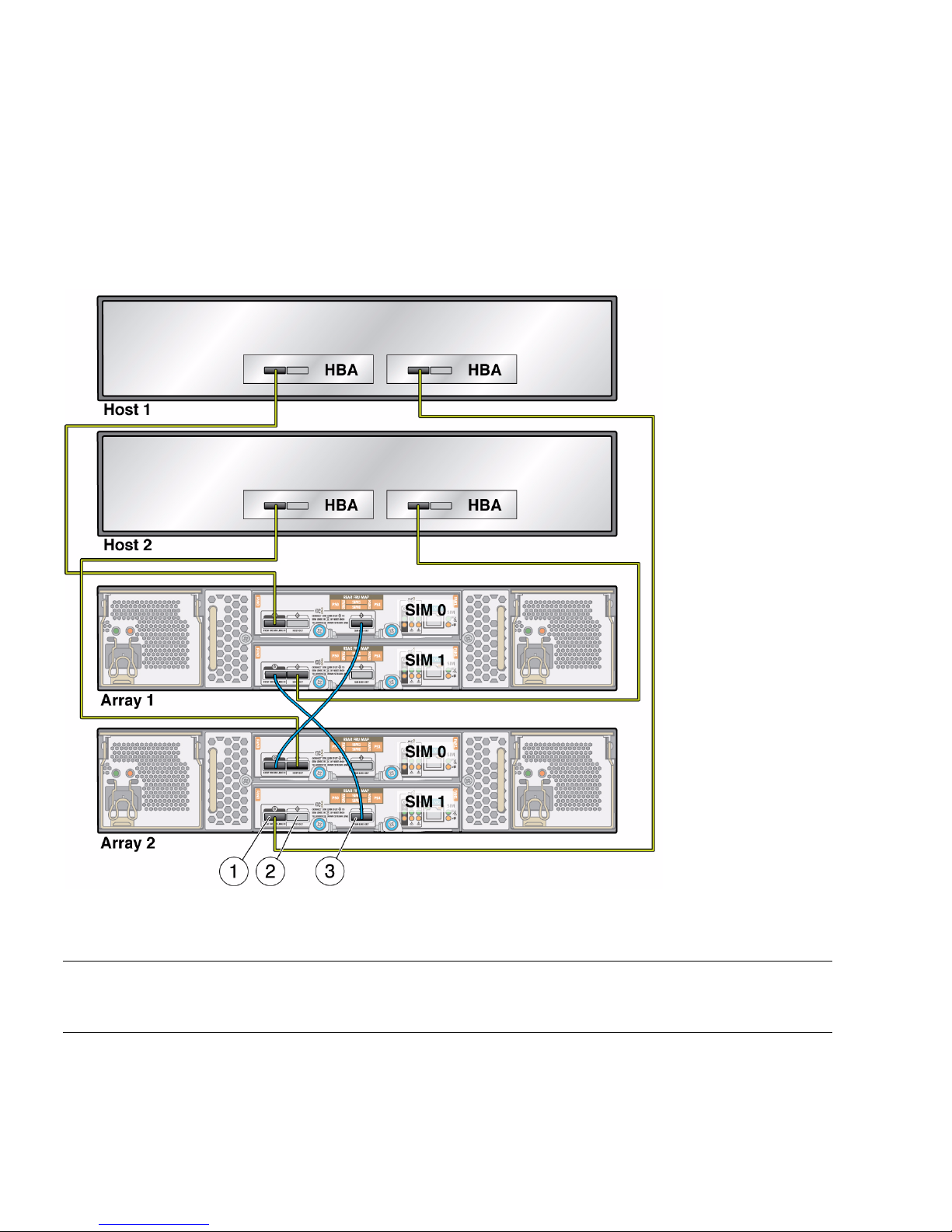
Multipathing With Two Arrays and Two Hosts
FIGURE 5-2 shows an example of cabling for multipath in a configuration with two
hosts, with two HBAs on each host, and two arrays cabled together.
FIGURE 5-2 Cabling Example for Multipathing With Two Arrays and Two Hosts
Figure Legend
1 Host or SIM Link In
2 Host Out
3 SIM Link Out
54 Sun Storage J4200/J4400 Array System Overview • June 2009
Page 71

Multipathing With Two Arrays and One Host
FIGURE 5-3 shows an example of cabling for multipath in a configuration with one
host, with two HBAs on that host, and two arrays cabled together.
FIGURE 5-3 Cabling Example for Multipathing With Two Arrays and One Host
Figure Legend
1 Host or SIM Link In
2 Host Out
3 SIM Link Out
Chapter 5 SAS Multipathing 55
Page 72

Enabling and Disabling Multipathing in
the Solaris Operating System
This sections describes how to enable and disable multipathing in the Solaris 10,
update 6, operating system.
Use the stmsboot command to enable multipathing in the Solaris 10, update 6,
operating system. stmsboot manages enumeration of multipath–capable devices
with multipathing; it has these characteristics:
■ Multipathing-enabled devices are enumerated under scsi_vhci(7D).
■ Multipathing-disabled devices are enumerated under the physical controller.
This section describes the stmsboot(1M) administration program for multipathing.
Device Renaming
In the /dev and /devices trees, multipathing-enabled devices receive new names
that indicate that they are under multipathing control.
■ This means a device has a different name from its original name (after enabling)
when it is under multipathing control.
■ The stmsboot command automatically updates /etc/vfstab and dump
configuration to reflect the device names changes when enabling or disabling
Multipathing.
■ One reboot is required for changes to take effect.
stmsboot Options
TABLE 5-3 describes the options supported by stmsboot(1M).
TABLE 5-3 stmsboot Options
-e [-D fp | mpt] Enables multipathing on all supported multipath-capable controller ports.
• Multipath-capable ports include SAS (mpt[7D]) controller ports.
• Prompts you to reboot.
• During reboot, vfstab and the dump configuration update to reflect the
device-name changes.
• Specifying -D mpt limits the enabling operation to ports attached using the
specified driver.
56 Sun Storage J4200/J4400 Array System Overview • June 2009
Page 73

TABLE 5-3 stmsboot Options (Continued)
-d [-D fp | mpt] Disables multipathing on all supported multipath-capable controller ports.
• Multipath-capable ports include SAS (mpt[7D]) controller ports.
• Prompts you to reboot.
• During reboot, vfstab and the dump configuration update to reflect the device
name changes.
• Specifying -D mpt limits the disabling operation to ports attached using the
specified driver.
-u Updates vfstab and the dump configuration after manually enabling or
disabling multipathing on specific multipath- capable controller ports.
• Prompts you to reboot.
• During reboot, vfstab and the dump configuration update to reflect the
device name changes.
-L Displays the device name changes from non-multipathing-device names to
multipathing device names on multipath-enabled controller ports.
If multipathing is not enabled, no mappings display.
-l
controller_number
stmsboot Conditions
stmsboot enables and disables multipathing on the host, with these conditions:
■ The utility automatically updates vfstab(4) and dumpadm(1M) configuration to
reflect device-name changes.
Note – The system administrator is responsible for modifying application
configuration (for example, backup software, DBMS, and so forth) to reflect updated
device names.
■ The -L and -l options display the mapping between multipathed and non-
multipathed device names, only after changes to the multipathing configuration
take effect; that is, following reboot after invoking stmsboot -e.
■ ZFS datasets, including ZFS root datasets, are correctly handled by stmsboot.
Displays the device-name changes from non-multipathing device names to
multipathing device names for the specified controller.
If multipathing is not enabled, no mappings display.
Chapter 5 SAS Multipathing 57
Page 74

▼ To Enable Multipathing on all Multipath-
Capable Controllers
Note – Multipathing is not supported on all controllers. After enabling
multipathing, only supported controllers are placed under multipathing control.
Non-supported controllers remain unchanged.
● Type:
# stmsboot -e
# stmsboot -e
Warning: stmsboot operates on each supported multipath-capable
controller detected in a host. In your system, these controllers
are
/devices/pci@780/pci@0/pci@8/SUNW,qlc@0/fp@0,0
/devices/pci@780/pci@0/pci@8/SUNW,qlc@0,1/fp@0,0
/devices/pci@7c0/pci@0/pci@1/pci@0,2/LSILogic,
/devices/pci@7c0/pci@0/pci@1/pci@0,2/LSILogic,
/devices/pci@7c0/pci@0/pci@1/pci@0,2/LSILogic,
/devices/pci@7c0/pci@0/pci@9/LSILogic,
/devices/pci@7c0/pci@0/pci@9/LSILogic,
sas@0
sas@0
sas@1
sas@1
sas@2
If you do NOT wish to operate on these controllers, please quit
stmsboot and re-invoke with -D { fp | mpt } to specify which
controllers you wish to modify your multipathing configuration for.
Do you wish to continue? [y/n] (default: y) y
Checking mpxio status for driver fp
Checking mpxio status for driver mpt
WARNING: This operation will require a reboot.
Do you want to continue ? [y/n] (default: y) y
The changes will come into effect after rebooting the system.
Reboot the system now ? [y/n] (default: y) y
Note – stmsboot updates the /etc/vfstab file and dump configuration to reflect
device-name changes during reboot.
The following conditions apply to the stmsboot -e, -d, and -u options:
■ Reboot immediately after running stmsboot.
58 Sun Storage J4200/J4400 Array System Overview • June 2009
Page 75

■ Ensure that eeprom(1m) boot device is set to boot from your current boot device;
stmsboot reboots the machine to complete the operation.
■ stmsboot saves a copy of your original /kernel/drv/mpt.conf and
/etc/vfstab files before modifying them.
▼ To Disable Multipathing on All Multipath-
Capable Controllers
● Type:
# stmsboot -d
# stmsboot -d
WARNING: stmsboot operates on each supported multipath-capable
controller detected in a host. In your system, these controllers
are
/devices/pci@780/pci@0/pci@8/SUNW,qlc@0/fp@0,0
/devices/pci@780/pci@0/pci@8/SUNW,qlc@0,1/fp@0,0
/devices/pci@7c0/pci@0/pci@1/pci@0,2/LSILogic,
/devices/pci@7c0/pci@0/pci@1/pci@0,2/LSILogic,
/devices/pci@7c0/pci@0/pci@1/pci@0,2/LSILogic,
/devices/pci@7c0/pci@0/pci@9/LSILogic,
/devices/pci@7c0/pci@0/pci@9/LSILogic,
sas@0
sas@0
sas@1
sas@1
sas@2
If you do NOT wish to operate on these controllers, please quit
stmsboot and re-invoke with -D { fp | mpt } to specify which
controllers you wish to modify your multipathing configuration for.
Do you wish to continue? [y/n] (default: y) y
Checking mpxio status for driver fp
Checking mpxio status for driver mpt
WARNING: This operation will require a reboot.
Do you want to continue ? [y/n] (default: y) y
The changes will come into effect after rebooting the system.
Reboot the system now ? [y/n] (default: y) y
Note – During reboot, /etc/vfstab and the dump configuration update to reflect
the device-name changes.
Chapter 5 SAS Multipathing 59
Page 76

▼ To Enable Multipathing on Multipath-Capable
Controller Ports
● Type:
# stmsboot
-D mpt -e
▼ To Disable Multipathing on Multipath-Capable
Controller Ports
● Type:
# stmsboot
-D mpt -d
Configuring Multipathing on Selected Ports
To enable multipathing on specific ports and disable multipathing on others, edit the
/kernel/drv/mpt.conf file. To update vfstab(4) and dumpadm(1M)
configurations to reflect the changed device names, type:
# stmsboot -u
Dynamic Discovery of SAS Devices
SAS devices, added and removed dynamically with the mpt(7d) driver, enable your
system to detect specific targets and LUNs attached, with these conditions:
■ If you add or remove a device in your SAS domain, messages are written to the
/var/adm/messages file indicating presence or removal.
■ If a device has been added, it is visible to, and available by, the format(1m)
command.
Note – To clean up the CTD# for your device tables, run the following command:
devfsadm -C.
60 Sun Storage J4200/J4400 Array System Overview • June 2009
Page 77

Enabling and Disabling Multipathing in
the Windows Operating System
This section describes how to enable and disable multipathing in the
Windows 2008 operating system.
▼ To Enable Multipathing in Windows 2008
1. From the Start menu, select Server Manager, as shown in FIGURE 5-4.
The Server Manager opens.
FIGURE 5-4 Start Menu With Server Manager Selection
2. Select Features from the list of folders on the left to open the Features panel, as
shown in
FIGURE 5-5.
Chapter 5 SAS Multipathing 61
Page 78

FIGURE 5-5 Server Manager Feature Display
In the Features panel, you can click the Features Summary arrow to open or close
the Features Summary and click the Features arrow to view the status of installed
features.
3. Click Add Features to enable the Add Features Wizard.
The Add Features Wizard Select Features window opens with the default Features
selected and a list of optional features available for installation in your system, as
shown in
FIGURE 5-6.
62 Sun Storage J4200/J4400 Array System Overview • June 2009
Page 79

FIGURE 5-6 Add Features Wizard Select Features Window
4. Select the Multipath I/O option from the Message Queuing sublist.
5. Click Next.
The Add Features Wizard Confirm Installation Selections window opens, as shown
in
FIGURE 5-7.
FIGURE 5-7 Confirm Installation Selections Window
6. Click Install.
The Add Features Wizard Installation Results window opens as shown in
FIGURE 5-8.
Chapter 5 SAS Multipathing 63
Page 80

FIGURE 5-8 Add Features Wizard Installation Results Window
7. Click Close.
8. Close the Server Manager main window.
▼ To Discover Device Multipaths
1. From the Windows Start menu (FIGURE 5-4), select Administrative Tools.
The MPIO Properties window, as shown in
FIGURE 5-9 MPIO Properties Window
FIGURE 5-9..
64 Sun Storage J4200/J4400 Array System Overview • June 2009
Page 81

2. Select the Discover Multi-Paths tab, as shown in FIGURE 5-10.
FIGURE 5-10 MPIO Properties Window Device Multi-Paths Tab
3. Highlight the Device Hardware for which you want to discover multipaths, as
shown in
FIGURE 5-11.
Chapter 5 SAS Multipathing 65
Page 82

FIGURE 5-11 Highlighted Device Hardware for Discovering Multipaths
4. Click OK.
The Reboot Required window opens, as shown in
FIGURE 5-12 Reboot Required Window
FIGURE 5-12.
5. Click Yes.
Note – For best results, after reboot, log in and change the default settings of the
MPIO policies. See “To Select a Load Balancing Policy” on page 68.
66 Sun Storage J4200/J4400 Array System Overview • June 2009
Page 83

▼ To Select a Load Balancing Policy
1. From the Windows Start menu, select Server Manager, as shown in FIGURE 5-4.
2. Select Diagnostics > Device Manager from the list of folders on the left to open
the Device Manager window, as shown in
FIGURE 5-13 Device Manager Window
3. Click the Device name.
FIGURE 5-13.
4. Click Disk drives.
The list of disk drives opens, as shown in
FIGURE 5-13.
5. Move your cursor over the device drive name for which you want information.
6. Right-click to open a menu and select Properties, as shown in
FIGURE 5-14.
Chapter 5 SAS Multipathing 67
Page 84

FIGURE 5-14 Menu to Modify Device Configuration
The Disk Drive Properties window opens, as shown in FIGURE 5-15.
FIGURE 5-15 Disk Drive Properties Window
68 Sun Storage J4200/J4400 Array System Overview • June 2009
Page 85

7. Use the drop-down menu to select a load-balancing policy, as shown in
FIGURE 5-16.
The choices for load-balancing policies are listed in
TABLE 5-4. By default, the Fail
Over Policy is configured. For best results with the J4200/J4400 array, use the
Round Robin policy.
TABLE 5-4 Load Balance Policies
Load Balance Policy Description
Fail Over Only The failover policy employs one active/optimized path and all other paths are
active/unoptimized, standby, or unavailable. The non-active/optimized paths
will be tried round-robin upon failure of the active/optimized path until an
available path is found.
Round Robin The round robin policy attempts to evenly distribute incoming requests to all
processing paths.
Round Robin with
Subset
The round robin with subset policy executes the round robin policy only on
paths designated as active/optimized. The non-active/optimized paths will be
tried on a round-robin approach upon failure of all active/optimized paths.
Least Queue Depth The least queue depth policy compensates for uneven loads by distributing
proportionately more I/O requests to lightly loaded processing paths.
Weight Paths The weighted paths policy allows the user to specify the relative processing load of each
path. A large number means that the path priority is low
FIGURE 5-16 Round Robin Load Balance Policy Selected
Chapter 5 SAS Multipathing 69
Page 86

8. Click OK.
Note – Load balance policie are set on a per-device basis. Repeat this procedure for
each disk drive.
▼ To Disable Multipathing in Windows 2008
1. From the Windows Start menu, select Administrative Tools > MPIO, as shown
in
FIGURE 5-17.
The MPIO Properties window opens, as shown in
FIGURE 5-17 Selecting Administrative Tools > MPIO From the Start Menu
FIGURE 5-18.
70 Sun Storage J4200/J4400 Array System Overview • June 2009
Page 87

FIGURE 5-18 MPIO Properties Window
2. Highlight a device in the list, as shown in FIGURE 5-19.
Chapter 5 SAS Multipathing 71
Page 88

FIGURE 5-19 Highlighting Device For Which to Disable Multipathing
3. Click Remove.
The Reboot Required window opens, as shown in
FIGURE 5-20 Reboot Required Window
FIGURE 5-20.
4. Click Yes.
The system reboots.
5. After reboot, select Administrative Tools > MPIO from the Windows Start
menu.
The MPIO Properties window opens, showing the device removed from the list,
as shown in
FIGURE 5-21.
72 Sun Storage J4200/J4400 Array System Overview • June 2009
Page 89

FIGURE 5-21 MPIO Properties Window With Device Removed From List
6. Repeat Step 2 through Step 5 until all devices are removed from the Device
Hardware Id list.
7. From the Windows Start menu, select Server Manager to open the Server
Manager window.
8. Select Features from the list of folders on the left to open the Features panel, as
shown in
FIGURE 5-22.
Chapter 5 SAS Multipathing 73
Page 90

FIGURE 5-22 Server Manager Window With Features Panel Open
9. Select Remove Features.
The Remove Features Wizard window opens, as shown in
FIGURE 5-23.
74 Sun Storage J4200/J4400 Array System Overview • June 2009
Page 91

FIGURE 5-23 Remove Features Wizard Window
10. Highlight Multipath I/O from the Message Queuing sublist.
The Confirm Removal Selections window opens, as shown in
FIGURE 5-24 Confirm Removal Selections Window
FIGURE 5-24.
Chapter 5 SAS Multipathing 75
Page 92

11. Click Remove.
The Removal Results window opens, as shown in
FIGURE 5-25 Removal Results Window
12. Click Close.
The system asks if you want to restart the server now, as shown in
FIGURE 5-25.
FIGURE 5-26.
FIGURE 5-26 Restart Now Window
13. Click Yes.
When the sever has restarted, the Removal Results window opens, as shown in
FIGURE 5-27.
76 Sun Storage J4200/J4400 Array System Overview • June 2009
Page 93

FIGURE 5-27 Removal Results Window
Enabling and Disabling Multipathing in
the Linux Operating System
This section describes how to enable and disable multipathing in supported versions
of the Linux operating system.
▼ To Enable Multipathing in Linux
1. Attach a J4200 or a J4400 to a server with a supported version of Linux installed.
2. On the server, edit or create the /etc/multipath.conf file.
3. Reboot the server.
4. After the reboot, make sure that the OS discovers all the disks in the
J4200/J4400 arrays either by using the Linux commands, fdisk or lsscsi.
5. Partition any disks you want to the desired sizes.
6. Use the Linux command modprobe to add the loadable kernel modules dm-
multipath and dm-round-robin.
# modprobe dm-multipath
# modprobe dm-round-robin
Chapter 5 SAS Multipathing 77
Page 94

7. Start the multipathd daemon.
For Linux SUSE 9, use the following command:
# multipathd -v0
For other supported Linux versions, use the following command:
# service multipathd start
8. Start the multipathing device mapper target autoconfig.
# multipath -v2
9. List the multipath devices that have been created.
# multipath -ll
The output should list the same number of devices as there are disks in the
J4200/J4400 arrays; it will look similar to the following:
35000c5000357625bdm-2 SEAGATE,ST340008SSUN0.4
[size=373G][features=0][hwhandler=0]
\_ round-robin 0 [prio=2][active]
\_ 0:0:0:0 sda 8:0 [active][ready]
\_ 1:0:0:0 sdm 8:192 [active][ready]
▼ To Disable Multipathing in Linux
1. If a RAID volume, LVM volume, or volume mount have been placed over the
device node of the multipathed disk, quiesce the volume.
2. Use the multipath -f command to disable multipathing to a specific device.
multipath -f mpath1
3. Use the multipath -F command to disable multipathing on all multipathed
devices.
multipath -F
Note – If the message map in use appears for a device when you attempt to
disable multipathing, the device is still in use. You must unmount or otherwise
quiesce the device before you can disable multipathing. If you cannot quiesce the
device, edit the /etc/multipath.conf file to exclude the device and then reboot
the server.
78 Sun Storage J4200/J4400 Array System Overview • June 2009
Page 95

Chapter 5 SAS Multipathing 79
Page 96

80 Sun Storage J4200/J4400 Array System Overview • June 2009
Page 97

Chapter 5 SAS Multipathing 81
Page 98

82 Sun Storage J4200/J4400 Array System Overview • June 2009
Page 99

CHAPTER
6
Troubleshooting and Hardware
Replacement with Service Advisor
Use the information in this chapter to help you troubleshoot your J4200/J4400 Array.
This chapter contains the following sections:
■ Service Advisor
■ Basic Service Procedures
■ Troubleshooting
Service Advisor
The Sun StorageTek Common Array Manager software includes the Service Advisor
application, which provides guided wizards with system feedback for hardware
replacement of Customer Replaceable Units (CRUs). In addition, Service Advisor
provides troubleshooting procedures for alarms.
Before you can access Service Advisor procedures, you must have already installed
the Common Array Manager software, as described in:
■ Sun StorageTek Common Array Manager User Guide for the J4000 Array Family (820-
3765-nn)
Host management, data host management, and remote command line interface (CLI)
functions are performed by the Sun StorageTek Common Array Manager software.
The CRU replacement procedures available through the Sun StorageTek Common
Array Manager Service Advisor application include:
■ Disks
■ Power Supplies
■ Fans
83
Page 100

■ Power Supply/Fan
■ SIMs
■ Chassis
Accessing Service Advisor Procedures
To launch Service Advisor and access hardware replacement procedures:
1. Log on to the Sun Java Web Console on the management software host.
For example, https://management_host_address:6789
2. In the Storage section of the Sun Java Web Console page, select Sun StorageTek
Common Array Manager.
The navigation pane and the Storage System Summary page appear.
3. Select an array under Storage Systems.
4. At the top right of the Storage System Summary page, click Service Advisor.
The Service Advisor application is displayed in a separate window.
5. In the left pane, select the type of hardware replacement procedure you want to
perform:
■ CRU/FRU Removal/Replacement Procedures
■ X-Options
■ Array Troubleshooting Procedures
■ Service Only
Note – Service-only procedures are password protected for access by Sun service
personnel only. Contact a Sun service representative for further information and
assistance with service only procedures.
6. To view a procedure, in the right pane either select it or expand its category, and
select the hardware component that corresponds to the procedure.
84 Sun Storage J4200/J4400 Array System Overview • June 2009
 Loading...