

Page 1

Sun StorageTek
TM
Crypto
Key Management System
HP LTO4 Encryption-Capable Tape Drives
Technical Brief
Part Number: 316196601
Revision: A
Page 2

Page 3

Crypto Key Management System
Version 2.0
HP LTO4 Tape Drive
Technical Brief
Sun Microsystems, Inc.
www.sun.com
Part Number: 316196601
June 2008
Revision: A
Page 4

Copyright © 2008 Sun Microsystems, Inc., 4150 Network Circle, Santa Clara, California 95054, U.S.A. All rights reserved.
Sun Microsystems, Inc. has intellectual property rights relating to technology embodied in the product that is described in this
document.In particular, and without limitation, these intellectual property rights may include one or more of the U.S. patents listed at
http://www.sun.com/patents and one or more additional patents or pending patent applications in the U.S. and in other countries.
THIS PRODUCT CONTAINS CONFIDENTIAL INFORMATION AND TRADE SECRETS OF SUN MICROSYSTEMS, INC. USE,
DISCLOSURE OR REPRODUCTION IS PROHIBITED WITHOUT THE PRIOR EXPRESS WRITTEN PERMISSION OF SUN
MICROSYSTEMS, INC.
Use is subject to license terms. This distribution may include materials developed by third parties.This distribution may include
materials developed by third parties.Parts of the product may be derived from Berkeley BSD systems, licensed from the University of
California.
UNIX is a registered trademark in the U.S. and in other countries, exclusively licensed through X/Open Company, Ltd.Sun, Sun
Microsystems, the Sun logo, Solaris, Sun StorageTek Crypto Key Management System, StorageTek and the StorageTek logo are
trademarks or registered trademarks of Sun Microsystems, Inc. in the U.S. and other countries.
Products covered by and information contained in this service manual are controlled by U.S. Export Control laws and may be subject
to the export or import laws in other countries. Nuclear, missile, chemical biological weapons or nuclear maritime end uses or end
users, whether direct or indirect, are strictly prohibited. Export or reexport to countries subject to U.S. embargo or to entities identified
on U.S. export exclusion lists, including, but not limited to, the denied persons and specially designated nationals lists is strictly
prohibited. Use of any spare or replacement CPUs is limited to repair or one-for-one replacement of CPUs in products exported in
compliance with U.S. export laws. Use of CPUs as product upgrades unless authorized by the U.S. Government is strictly prohibited.
DOCUMENTATION IS PROVIDED “AS IS” AND ALL EXPRESS OR IMPLIED CONDITIONS, REPRESENTATIONS AND
WARRANTIES, INCLUDING ANY IMPLIED WARRANTY OF MERCHANTABILITY, FITNESS FOR A PARTICULAR PURPOSE OR
NON-INFRINGEMENT, ARE DISCLAIMED, EXCEPT TO THE EXTENT THAT SUCH DISCLAIMERS ARE HELD TO BE LEGALLY
INVALID.
Copyright © 2008 Sun Microsystems, Inc., 4150 Network Circle, Santa Clara, California 95054, Etats-Unis. Tous droits réservés.
Sun Microsystems, Inc. détient les droits de propriété intellectuels relatifs à la technologie incorporée dans le produit qui est décrit
dans ce document.
En particulier, et ce sans limitation, ces droits de propriété intellectuelle peuvent inclure un ou plus des brevets américains listés à
l'adresse http://www.sun.com/patents et un ou les brevets supplémentaires ou les applications de brevet en attente aux Etats - Unis
et dans les autres pays.
CE PRODUIT CONTIENT DES INFORMATIONS CONFIDENTIELLES ET DES SECRETS COMMERCIAUX DE SUN
MI CRO SYS TEM S, I NC. SON UTI LIS ATIO N, S A DI VUL GATI ON E T SA REP ROD UCT ION SON T IN TER DITE S SA NS L
AUTORISATION EXPRESSE, ECRITE ET PREALABLE DE SUN MICROSYSTEMS, INC.
L'utilisation est soumise aux termes de la Licence.Cette distribution peut comprendre des composants développés par des tierces
parties.Cette distribution peut comprendre des composants développés par des tierces parties.Des parties de ce produit pourront être
dérivées des systèmes Berkeley BSD licenciés par l'Université de Californie.
UNIX est une marque déposée aux Etats-Unis et dans d'autres pays et licenciée exclusivement par X/ Open Com pan y, L td. Sun , Su n
Microsystems, le logo Sun, Solaris, Sun StorageTek Crypto Key Management System, StorageTek et le logo StorageTek sont des
marques de fabrique ou des marques déposées de Sun Microsy ste ms, Inc . au x Et ats -Un is e t da ns d 'au tre s pa ys.
Ce produit est soumis à la législation américaine en matière de contrôle des exportations et peut être soumis à la règlementation en
vigueur dans d'autres pays dans le domaine des exportations et importations. Les utilisations, ou utilisateurs finaux, pour des armes
nucléaires, des missiles, des armes biologiques et chimiques ou du nucléaire maritime, directement ou indirectement, sont strictement
interdites. Les exportations ou reexportations vers les pays sous embargo américain, ou vers des entités figurant sur les listes
d'exclusion d'exportation américaines, y compris, mais de manière non exhaustive, la liste de personnes qui font objet d'un ordre de ne
pas participer, d'une façon directe ou indirecte, aux exportations des produits ou des services qui sont régis par la législation
américaine en matière de contrôle des exportations et la liste de ressortissants spécifiquement désignés, sont rigoureusement
interdites. L'utilisation de pièces détachées ou d'unités centrales de remplacement est limitée aux réparations ou à l'échange standard
d'unités centrales pour les produits exportés, conformément à la législation américaine en matière d'exportation. Sauf autorisation par
les autorités des Etats-Unis, l'utilisation d'unités centrales pour procéder à des mises à jour de produits est rigoureusement interdite.
LA DOCUMENTATION EST FOURNIE “EN L'ETAT” ET TOUTES AUTRES CONDITIONS, DECLARATIONS ET GARANTIES
EXPRESSES OU TACITES SONT FORMELLEMEN T EX CLU ES, DAN S LA MES URE AUTORISEE PAR LA LOI APPLICABLE, Y
COMPRIS NOTAMMENT TOUTE GARANTIE IMPLICITE RELATIVE A LA QUALITE MARCHANDE, A L'APTITUDE A UNE
UTILISATION PARTICULIERE OU A L'ABSENCE DE CONTREFACON.
We welcome your feedback. Use the OpinionLab [+] feedback system on the documentation Web site or Send your comments to:
Sun Learning Services
Sun Microsystems, Inc.
500 Eldorado Blvd.
Mailstop: UBRM06-307
Broomfield, CO 80021-6307
USA
Please include the publication name, part number, and edition number in your correspondence if they are available.
This will expedite our response.
Please
Recycle
Page 5

Contents
Preface v
Organization v
Related Information v
Additional Information vi
1. Introduction 1
Drive Tray 2
Specifications 3
Compatibility 5
Order Numbers 6
2. Dione Card 7
Firmware Requirements 7
Dione Card Components 8
Connecting to the Dione Card 9
KMS Operations 10
Key Lifecycle 10
Media RFID Chips 12
Media Types 12
Removal and Replacement 14
Removal 14
3. Virtual Operator Panel 17
VOP Prerequisites 18
Computer Hardware Requirements 18
Operating System Certification 18
Java Runtime Environment Requirement 18
316196601 • Revision: A iii
Page 6

Using VOP 19
Start VOP 20
Diagnose Drive Tab 23
Run LED Diagnostic Test 23
Run Loopback Test 24
Get Log 25
Load Firmware 25
iv KMS: LTO4 Technical Brief • June 2008 Revision: A • 316196601
Page 7
Preface
This technical brief is intended for Sun StorageTek
and anyone responsible for planning the installation of the Crypto Key
Management System (KMS) encryption solution.
Organization
This guide has the following organization:
Chapter Use this chapter to:
Chapter 1, “Introduction”
Chapter 2, “Dione Card”
Chapter 3, “Virtual Operator Panel”
Related Information
TM
representatives, customers,
These publications contain the additional information:
Publication Description Part Number
Crypto Key Management System Systems Assurance Guide StorageTek: 31619480x
Crypto Key Management System Installation and Service Manual StorageTek: 31619490x
Crypto Key Management System Administrator Guide StorageTek: 31619510x
316196601 • Revision: A v
Page 8

Preface
Additional Information
Sun Microsystems, Inc. (Sun) offers several methods to obtain additional
information.
Sun’s External Web Site
Sun’s external Web site provides marketing, product, event, corporate, and service
information. The external Web site is accessible to anyone with a Web browser and
an Internet connection.
The URL for the external Web site is: http://www.sun.com
The URL for StorageTek™ brand-specific information is:
http://www.sun.com/storagetek/
Documentation and Download Web Sites
Web sites that enable customers, members, and employees to search for technical
documentation, downloads, patches, features, and articles include:
■ Documentation: http://docs.sun.com/app/docs (customers)
■ Internal access: http://docs.sfbay.sun.com/app/docs (internal)
■ Sun Download Center: http://www.sun.com/download/index.jsp (customers)
■ Sun Partner Exchange: https://spe.sun.com/spx/control/Login (partners)
■ Uniform Software Repository: http://dlrequest.sfbay.sun.com:88/usr/login
(internal)
If your customer does not already have a Sun Online Account they will need to
register. For a new account, go to: https://reg.sun.com/register
For more information about Sun StorageTek products, got to:
http://sunsolve.sun.com/handbook_pub/validateUser.do?target=STK/STK_index
Partners Site
The Sun StorageTek Partners site is a Web site for partners with a StorageTek
Partner Agreement. This site provides information about products, services,
customer support, upcoming events, training programs, and sales tools to support
StorageTek Partners. Access to this site, beyond the Partners Login page, is
restricted. On the Partners Login page, employees and current partners who do
not have access can request a login ID and password and prospective partners can
apply to become StorageTek resellers.
The URL for partners with a Sun Partner Agreement is:
http://www.sun.com/partners/
vi KMS: LTO4 Technical Brief • June 2008 Revision: A • 316196601
Page 9

CHAPTER
1
Introduction
Overview The Hewlett Packard (HP) LTO4 is the fourth-generation of Ultrium, Linear
Tape-Open tape drives. This generation offers more capacity and increased
performance than earlier versions of LTO tape drives.
Encryption
Capable
Media
(Native capacity)
The Hewlett Packard LTO4 is the first, non-StorageTek T-Series tape drive to
support the Crypto Key Management System Version 2.0.
This encryption-capability requires a special, custom designed, Ethernet
card—called the Dione card—that enables the LTO4 drive to connect to and
interface with the Key Management System (KMS) network.
With this connection, the LTO4 is capable of communicating with the KMS
to transfer encryption keys over the secure network.
Note: The HP LTO4 can only use one encryption key at a time. During a read
operation, if another encryption key is found, the Dione card requests the
key directly from the KMS.
The HP LTO4 drive with LTO4 media can store up to 800 GB of data.
This drive can also read and write on LTO3 media (400 GB), and provides
read-only capabilities with LTO2 media (200 GB).
The LTO4 tape drive also supports Write Once, Read Many (WORM) secure
media. This non-erasable, non-rewritable media meets several compliance
regulations such as HIPAA, Sarbanes-Oxley, and SEC 17A-4.
Note: Encryption is only possible using LTO4 media, including LTO4
WORM media, with the HP LTO4 tape drive. If you insert LTO2 or LTO3
media, encryption will be disabled.
Interfaces
(Native rates)
316196601 • Revision: A 1
The HP LTO4 drive supports up to 120 MB/s data transfer rates using Data
Rate Matching (DRM). This features allows the tape drive to dynamically
and continuously adjust the speed of the drive, from 40 to 120 MB/s for
maximum performance
Interface support for the HP LTO4 includes:
■ Ultra 320 Small Computer System Interface (SCSI)
■ 4 Giga-bits per second (Gbps) Fibre Channel
Page 10
Drive Tray
Installing this tape drive in one of Sun StorageTek’s automated tape configurations
offers customers with an even wider choice of tape-based storage solutions.
■ Server compatibility: Fibre Channel and SCSI models on popular (qualified)
platforms from vendors such as Sun, HP, IBM, and Dell.
■ Software compatibility: Support for an extensive list of software applications
such as ACSLS, HP, CA, VERITAS, Legato, Tivoli, and many more.
■ Support for WORM media: Allows for unalterable backups using Write-Once
Read-Many (WORM) media to meet compliance regulations such as HIPAA,
Sarbanes-Oxley, SEC 17A-4.
■ Mid-range class: Delivers confidence with a wide variety of supported backup
applications.
Drive Tray
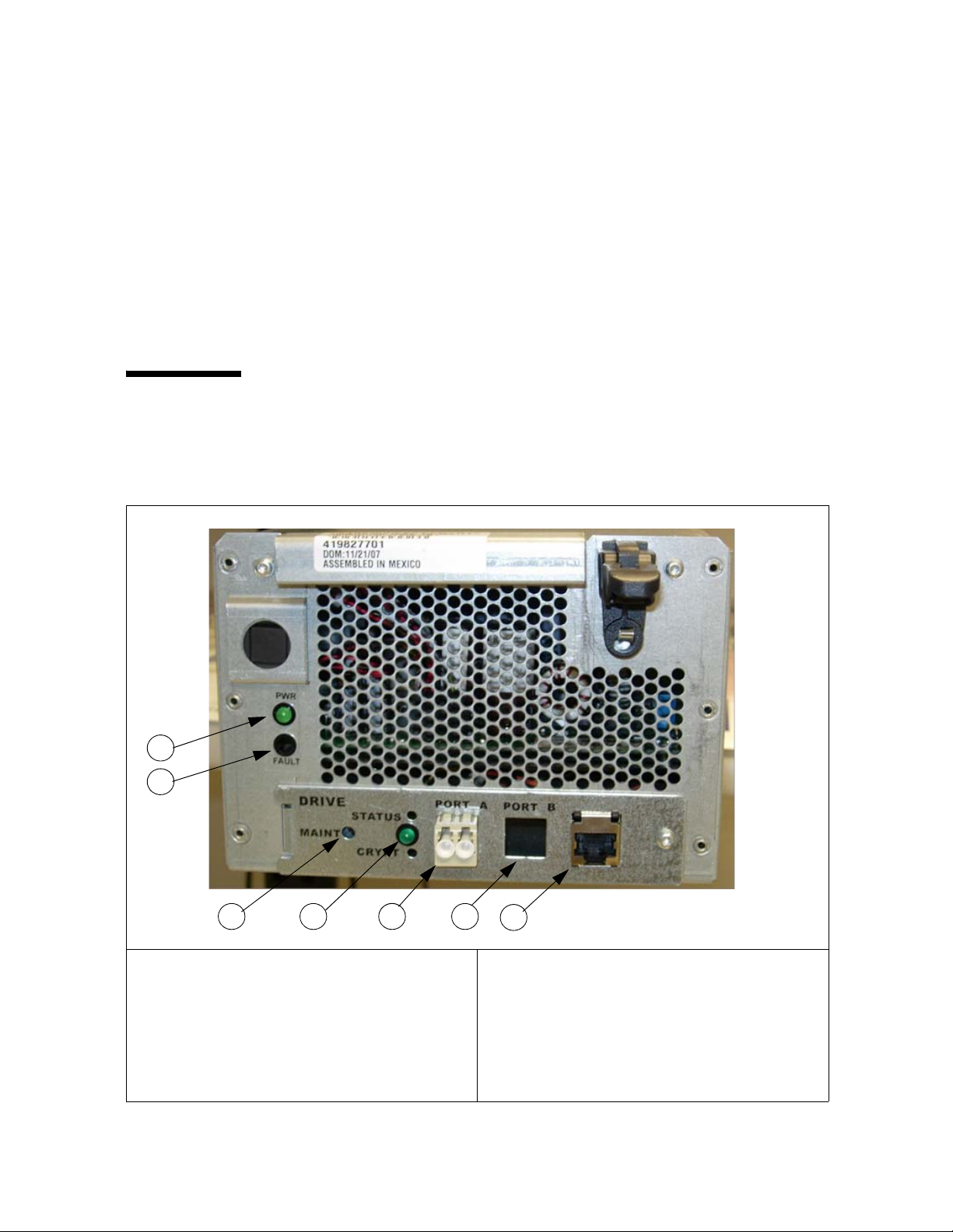
FIGURE 1-1 shows an example of an LTO4 tape drive mounted in a drive tray.
FIGURE 1-1 LTO4 Tape Drive in Drive Tray—SL8500
1
2
3 5 6
1. “PWR” = power indicator (green)
2. “FAULT” = Fault indicator (red)
3. “MAINT” = Recessed button that resets the
Dione card
4. The green LED is ON during the Dione card IPL
and when an encryption/decryption key is
present during drive operation
2 KMS: LTO4 Technical Brief • June 2008 Revision: A • 316196601
4
7
5. “PORT A” = Fibre Channel interface port
6. “PORT B” = Not used
7. RJ-45 connector. This port is auto sensing to 10
Mbps/100 Mbps data rates and used to:
■ Configure the network
■ Enroll the agent on the KMS
■ Retrieve the diagnostic log file
■ Upgrade Dione card firmware
Page 11

Specifications
Specifications
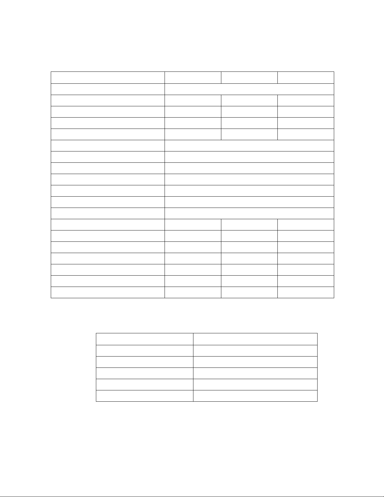
TABLE 1-1 Tape Drive Specifications
LTO 2 LTO 3 LTO 4
Physical Specifications
Height 8.25 cm (3.25 in.) 8.25 cm (3.25 in.) 8.25 cm (3.25 in.)
Width 14.6 cm (5.75 in.) 14.6 cm (5.75 in.) 14.6 cm (5.75 in.)
Length (depth) 21.38 cm (8.4 in.) 21.38 cm (8.4 in.) 21.38 cm (8.4 in.)
Weight 2.1 kg (4.6 lb) 2.24 kg (4.94 lb) 2.24 kg (4.94 lb)
Performance Specifications
Capacity (native) 200 GB 400 GB 800 GB
Transfer rate (native) 30 MB/s 80 MB/s 120 MB/s
Streaming range (native) 13.7 to 35.6 MB/s 27 to 80 MB/s 40 to 120 MB/s
Data Buffer size 64 MB 128 MB 128 MB
Number of tracks 512 704 896
Load to ready * 15–24 sec 19 sec 19 sec
Access time-average (to first file) 64–75 sec 72 sec 62 sec
TABLE 1-1 provides a comparison of tape drive specifications.
Tape speed (meters per second) 5.50 m/s 5.32 m/s 7.0 m/s
Tape read/write speed 6.20 m/s 5.32 m/s 6.20 m/s
Rewind time (maximum/average) 104/52 sec 98/49 sec 124 sec
Unload time 13–19 sec 19 sec 19 sec
Cleaning time 58 to 152 sec
Interface Support (SCSI)
(Fibre Channel)
Ultra3 SCSI (LVD)
FC1
Ultra-320 (LVD)
FC2
Ultra-320 (LVD)
FC4
MTBF (100% duty cycle) 250,000 hrs 250,000 hrs 250,000 hrs
Media/Format Compatibility
Read LTO 1 , LTO2 LTO 1, 2 , 3 LTO 2, 3, 4
Write LTO 1 , LTO2 LTO2, LTO3 LTO3, LTO4
Note: HP drives support the LTO standard for backward compatibility, which is to write back
one generation and read back two generations.
Power
Consumption 38 W 35 W 30 W
Interface Codes:
Fibre Channel: FC1 = Fibre Channel 1Gb, FC2 = Fibre Channel 2Gb, FC4 = Fibre Channel 4Gb
Note: * Encryption-capable and un-initialized WORM cartridges can take longer to load.
316196601 • Revision: A Chapter 1 Introduction 3
Page 12
Specifications
TABLE 1-2 provides a comparison of media specifications.
TABLE 1-2 Media Specifications
Specification LTO 2 LTO 3 LTO 4
Tape Base film PEN (Poly-Ethylene-Naphthalate)
Tape le n gt h 609m 680m 820m
Tape length used for data 580m 648m 783m
Tape wi d th 12.65 mm 12.65 mm 12.65 mm
Tape dimensional stability 1200 ppm 1200 ppm 900 ppm
Maximum tape speed 7.29 m/s
Rewind speed 7.00 m/s
Durability 1,000,000 passes
Cartridge Width 105.4±0.30 mm
Depth 102.0±0.30 mm
Height 21.5±0.25 mm
Weig ht 0.220 kg
Track density (TPI) 1260 1773 2212
Data tracks 512 704 896
Data channels 8 16 16
Number of wraps 64 44 56
Number of bands 4 4 4
Bit density 7.40 Kb/mm 9.64 Kb/mm 13.52 Kb/mm
Cartridge memory capacity 4096 bytes 4096 bytes 8192 bytes
TABLE 1-3 lists the reliability specifications.
TABLE 1-3 Reliability Specifications
Description Specification
MTBF (100% duty cycle) 250,000 hours
Load/unload life 100,000 swaps
Head life 60,000 hours
Media durability 1,000,000 passes
Maximum cartridge use 20,000 threads
4 KMS: LTO4 Technical Brief • June 2008 Revision: A • 316196601
Page 13

Specifications
Compatibility
HP LTO Ultrium 4 drives are specified to interchange with un-encrypted data
cartridges from other tape drives that comply to the LTO U-28, U-316 and U-416
specifications:
Future compatibility:
In the future, HP LTO Ultrium drives will be capable of:
■ Reading and writing tapes from the current generation
■ Reading and writing tapes from one earlier generation
■ Reading tapes from two earlier generations
HP LTO Ultrium drives will always maintain write and read compatibility with
other manufacturers’ LTO Ultrium drives and tapes that meet the LTO Ultrium
format specification.
TABLE 1-4 LTO Media Compatibility
Capability
Native Capacity (Length) Format
Write Read
800 GB WORM LTO 4 Yes Yes
800 GB (820m) LTO4 Yes Yes
400 GB WORM LTO 3 Yes Yes
400 GB (680m) LTO3 Yes Yes
200 GB (580m) LTO2 No Yes
100 GB (580m) LTO1 No No
50 GB (290m) LTO1 No No
Note – Currently, only LTO4 media is encryption-capable on the LTO4 tape drives.
While LTO4 can read and “write” to LTO3 media, if an LTO4 drive encrypted data
on LTO3 media, then LTO3 drives could not read those tapes. Therefore, when
LTO3 media is inserted into an LTO4 drive, the encryption capability is disabled
and the drive will write non-encrypted data without notification.
316196601 • Revision: A Chapter 1 Introduction 5
Page 14

Order Numbers
Order Numbers
FIGURE 1-2 License Keys
LTO4 Encryption Key Marketing Number Description
Bundled X-HP-LTO4-EKEY-B One required per encryption enabled drive.
After market X-HP-LTO4-EKEY-A One required per encryption enabled drive.
License Keys
Bundled with the drive at time of sale.
After market for drives previously purchased.
Configured End Items
TABLE 1-5 Configured End Items—Order Numbers
Part Numbers Description
SL500
LTO4E-HP4FC-SL500Z LTO4 HP FC 4Gb SL500 Encryp Dr
LTO4E-HPSC-SL500Z LTO4 HP SCSI SL500 Encryp Dr
SL8500
LTO4E-HP4FC-SL85Z LTO4 HP FC 4Gb SL8500 EncrypDr
SL3000
LTO4E-HP4FC-SL30Z LTO4 HP FC 4Gb SL3000 EncrypDr
X-Options (Conversion Bills)
TABLE 1-6 Conversion Bill Numbers
Part Numbers Description
SL500
XHPLTO4E-FCUPL500Z Crypto drive upgrade for HP LTO4 FC SL500
XHPLTO4E-SCUP500Z Crypto drive upgrade for HP LTO4 SCSI SL500
SL3000/8500
XHPLTO4E-FCUP3085Z Crypto drive upgrade for HP LTO4 FC SL3000/SL8500
Dione Card
TABLE 1-7 Dione Card Part Number
Part Number Description
419954901 HP LTO4 Dione Card
6 KMS: LTO4 Technical Brief • June 2008 Revision: A • 316196601
Page 15

CHAPTER
2
Dione Card
The Dione card—pronounced (D - O - nee)—is a custom design that provides an
Ethernet interface for the HP LTO4 tape drive. With this interface, the HP LTO4
tape drive can:
■ Encrypt and decrypt data using the Sun StorageTek Crypto Key Management
System (KMS), Version
■ Configure and enroll the tape drive using the Virtual Operator Panel (VOP),
Version 1.0.12 or higher
Basically, the Dione card is a translation device between the serial interface on the
tape drive and the secure Ethernet port for use with the KMS.
The Dione card includes:
■ Telnet server for configuration and management
■ FTP server for installing new firmware and retrieving firmware trace logs
■ SOAP client (with TLS 1.0 support) for communication with the KMS
2.0 and above
Firmware Requirements
316196601 • Revision: A 7
The minimum firmware requirements include:
TABLE 2-1 Firmware Requirements
Component Version (or above)
Dione card 1.178
HP LTO4 tape drive H45S Fibre Channel
B44S SCSI
KMS Version 2.0 2.02
ACSLS 7.1 and 7.1.1 with PUT0701, or 7.2, and 7.3
SL8500 library 3.98B
SL3000 library 2.01 (SPS)—Requires approval
SL500 library i15 — 1300 (SPS)—Requires approval
L-Series 3.18.xx
Virtual Operator Panel 1.0.12
Page 16

Dione Card Components
Dione Card Components
The Dione card installs in the open area of the drive trays behind the tape drives.
Library drive trays that support this card are the:
■ SL8500
■ SL3000
■ SL500
■ L-Series
Each drive tray has its own unique configuration depending on the space in the
open area of the drive tray.
FIGURE 2-1 shows an example of a Dione card, which consists of:
■ Dione card
■ Ethernet connector (RJ-45)
■ Power connection (inline with the tape drive power)
■ Communications connection to the tape drive
■ Reset switch (on the drive tray rear panel)
FIGURE 2-1 Dione Card Components
■ Green Status LED (on the drive tray rear panel)
1. Dione card
2. Ethernet connection (RJ-45)
3. Reset switch
4. Green status LED
6. Inline power connection
7. Tape drive power connection
8. Tape drive communications connection
9. Reset switch connection (2 wires)
5. LED connection (2 wires)
8 KMS: LTO4 Technical Brief • June 2008 Revision: A • 316196601
Page 17

Dione Card Components
Connecting to the Dione Card
FIGURE 2-2 shows two ways to connect to the Dione card:
■ Point-to-point using a crossover cable
■ Network using a switch or hub and standard (straight-through) Ethernet cables
Note – The default IP address of the Dione card is 10.0.0.1.
This address is the same as the T-Series tape drives.
Because of this, the initial connection to the Dione card and LTO4 tape drive
should be with a crossover cable to set a new IP address. Then once the IP address
is set, you can connect the drive to the network for configuration and enrollment.
FIGURE 2-2 Connecting to the Dione Card
Point-to-Point: Crossover Cable Connection Network: Standard Ethernet Connection
See Chapter 3, “Virtual Operator Panel” for information.
Green LED operation:
When you power-on the LTO4 tape drive, the green LED lights for 30 seconds as
the Dione card performs an initial program load (IPL).
■ If the LED does not come on when power is applied (and there is power on the
tape drive) there is a problem with the Dione card.
■ If this LED does not go out after 30 seconds (approximately), there is a problem
with the Dione card.
After 30 seconds, the LED goes out and stays out until the tape drive is in an
encryption-capable mode (tape loaded, key available, encrypting or decrypting).
Reset Switch operation:
The reset switch performs one of three functions:
1. In normal operation, pressing this button resets the Dione as if at power-on.
2. Pressing and holding for more than 3 to 4 seconds resets all the stored settings to
their manufacturing defaults, and then resets the Dione as if at power-on.
3. When Running the LED Test it temporarily changes the mode of operation
allowing you to press the switch causing the LED to flash. The flashing stops
when the switch is released.
316196601 • Revision: A Chapter 2 Dione Card 9
Page 18

KMS Operations
KMS Operations
When the tape drive is powered-on, the Dione card communicates to the drive
over the serial port to take control of drive encryption and decryption.
HP LTO4 tape drives have the capability of storing one (1) key while encrypting or
decrypting data. Therefore; it is essential that these drives stay connected to the
KMS network for communications. Failover and load balancing will also occur
between the KMAs in the system (KMS).
The following is a brief description about how the drive implements encryption:
■ During write operations, when the backup application starts writing, the Write
command triggers the drive to request an encryption key from the Dione card.
The Dione creates a secure connection to the KMA and requests a key.
The KMA provides the key.
The Dione card unwraps the key and sends it to the drive, which continues with
the write operation.
■ During read operations, a similar set of operations occur.
The backup application sends a read request.
The drive recognizes that the data is encrypted and requests a decryption key
from the Dione card.
Note: The LTO4 tape format stores the metadata (key) along with encrypted
data. This gives the Dione card a method to retrieve the required key for
decryption.
The Dione card verifies the Key Associated Data in the data block to determine
the Key ID for that block and requests the corresponding key from the KMA.
Once the key has been received, it is sent to the drive and the read proceeds.
■ During media loads and unloads the Dione card monitors tape drive and
fetches the appropriate Data Unit (for loads) or clearing of the encryption status
(for unloads).
Key Lifecycle
Keys undergo a lifecycle based on the key policy. The lifecycle imposed by the
KMS is based on the NIST 800-57 guidelines and has two time periods:
■ Encryption period the time after a key is assigned that it can be used to encrypt.
■ Cryptoperiod the time period it can be used for decryption.
It is assumed the two periods start at the same time when the key is assigned.
FIGURE 2-3 shows an example of how these periods interacts.
10 KMS: LTO4 Technical Brief • June 2008 Revision: A • 316196601
Page 19

FIGURE 2-3 Key Lifecycle
A potential issue:
That LTO4 drive firmware will not request a write key in the following scenario:
Read, Space, Write-Filemark, Write.
The drive will use the same key obtained for the Read command to encrypt the
data provided for the Write command. The state of this key may be inappropriate
for writing due to the policy associated with the drive (an expired key).
KMS Operations
Work-Around:
Assign the drive’s Key Group having a key policy with a long encryption period.
An encryption period of a year or longer is recommended.
Details:
The LTO-4 drive firmware will not request a write key in the following scenario:
Read, Space, Write-Filemark, Write. The drive will use the key obtained from the
Read command to encrypt the data provided for the Write command.
Most applications go through this sequence of operations when
appending
data to a tape.
The end result is that encryption keys previously used on that tape will continue to
be used for write operations even if the state of the key has changed to expired or
compromised.
The encryption period is a user defined policy.
An encryption period of a year or longer is recommended to mitigate the risk of
write operations using an expired key. Most applications write sequentially to a
tape cartridge until it is full. It is rare that a customer would not fill a tape
cartridge with data within a year.
This is a low impact issue due to ability to mitigate exposure with a user defined
encryption period and due to the non-disruptive nature of the error. Data
encrypted with an expired key can still be accessed normally on future attempts to
append or restore.
It is recommended that the customer not destroy encryption keys as a means to
enforce data life-cycle management. Instead, enforce data life-cycle management
by expiring volumes through the backup and archive applications.
316196601 • Revision: A Chapter 2 Dione Card 11
Page 20

KMS Operations
At release, the functionality to set a key in a compromised state is not present.
This is a low impact issue due to the system assigning unique encryption keys for
each tape cartridge. It is rare that a compromised key scenario would ever be
encountered. If it was it would only impact future writes to a single tape cartridge.
This functionality will be implemented in the next drive firmware update.
Media RFID Chips
Use FIGURE 2-4 to connect the bulleted terms with the KMS Manager.
New data cartridges may not have the physical barcode information written to the
Radio Frequency Identification (RFID)
1
chip—also know as the cartridge
memory—in the LTO4 cartridge during the initial mount (load).
This requires updated library firmware, and not all libraries support this function.
Future updates to library firmware will correct this problem allowing the cartridge
memory to write the physical barcode. Libraries include:
■ SL8500 = supported (3.98B and above)
■ SL3000 = supported (2.01 and above)
■ SL500 = supported (i15)
■ L-Series = requires an update (3.18.xx)
The barcode information from the cartridge memory is passed to the KMS and
1
stored as additional metadata for a Data Unit (cartridge).
The External Tag field of the Data Unit contains the physical barcode information
2
when the library firmware update is available.
Refer to the Crypto KMS Administration Guide for more information about Data
Units and the ExternalTag field.
Note – When installing the HP LTO4 tape drive in an SL500 library, you must
disable the “Fast Load” option. Disabling this option allows the library and tape
drive to update the RFID chip with the physical barcode information.
This is not necessary for the SL3000 and SL8500 libraries.
Media Types
Important:
Encryption is only possible on LTO4 media, including LTO4 WORM media.
If an earlier media-type (such as an LTO3 data cartridge) is found in the drive,
encryption is disabled until that media is unloaded.
When fetching the Data Unit from the KMA, the Dione card sets the:
3
■ Description field to either “LTO4” or “LTO4WORM”
■ External Tag field if the library stored a barcode label in the Cartridge Memory
4
■ External Unique ID is the (vendor-unique) Cartridge Memory Attribute
1. Radio Frequency Identification (RFID) chips are also called cartridge memory chips.
The RFID chip contains information about the cartridge, the tape, and the performance
over time. This non-volatile storage information includes:
• Manufacturing information • Initialization information
• Usage • Tape directory
• Pass history • Error history
• Tape Alert flags • Status of the MIR
12 KMS: LTO4 Technical Brief • June 2008 Revision: A • 316196601
Page 21

FIGURE 2-4 provides an example of a KMS Manager display screen using the
elements from and HP LTO4 drive.
FIGURE 2-4 KMS Manager Data Unit List
KMS Operations
1
2 4
3
1. Data Unit ID (data cartridge)
2. External Tag (volume serial number)
3. Description (LTO4 or LTO4WORM)
4. External Unique ID (vendor-unique RFID contents)
316196601 • Revision: A Chapter 2 Dione Card 13
Page 22

Removal and Replacement
Removal and Replacement
Encryption-capable HP LTO 4 tape drives contain an Ethernet card, which is a field
replaceable unit (FRU). Depending on the library, each drive tray contains the card in a
different location; however, the removal and replacement procedures are similar.
For specific information about the drive trays, refer to:
SL8500 Modular Library System Installation Manual StorageTek: 96138
SL3000 Modular Library System Installation Manual StorageTek: 316194201
SL500 Modular Library System Installation Manual StorageTek: 96114
L700/1400 Library Installation Manual StorageTek: 95843
L180 Library Installation Manual StorageTek: 95896
If the manuals are not on hand, go to the Sun Documentation Web site at:
http://docs.sfbay.sun.com/app/docs/prod/tape.storage#hic
FIGURE 2-5 Dione Card and Connectors
1. Dione card
2. Ethernet connector
3. P5
4. Signal connector
5. Drive power jumper
6. Power connector to drive
7. P6
Removal
The following procedure basically describes how to remove and replace a Dione card:
1. Follow the procedures for taking the drive offline.
2. Follow the procedures for removing the drive from the library.
14 KMS: LTO4 Technical Brief • June 2008 Revision: A • 316196601
Page 23

Removal and Replacement
3. Place the drive and drive tray on a suitable work surface.
Caution:
Potential ESD damage: The encryption card contains ESD-sensitive components.
Make sure you follow proper ESD precautions.
4. Remove the two T9 screws from the top cover and remove the cover.
5. Remove the connectors from the HBD card.
6. Remove the four T10 screws that attach the drive to the tray.
7. Remove the T10 screw that attaches the encryption card.
8. Pull out the drive part way to gain access to the cables and connectors.
9. Remove the cable/connectors in this order:
■ Ethernet cable
■ P5
■ P6
■ Power cable
■ Signal cable
10. Remove the four T10 screws that fasten the card to its plate.
Replacement
Caution:
■ ESD-sensitive components. Make sure you follow the proper precautions.
■ Use care not to damage the thin, glass cable attached to J5. This cable is fragile
and easily damaged.
To replace the Dione card:
1. Obtain the encryption card and remove it from its wrapper.
2. Align the card on the plate and insert the T10 mounting screws.
3. Connect P5 and P6 to the card.
4. Plug in the following cables in this order:
■ Signal connector from the card to the rear of the drive
■ Drive power (from rear of the drive)
■ Power jumper
5. Insert the card and plate into its position and fasten it with one T10 screw.
6. Position the HBD card back into place.
7. Re-connect the cables to the HBD card.
8. Insert the drive and fasten it to the tray with four T10 screws.
9. Replace the top cover plate and fasten it with two T10 screws.
10. Insert the drive tray into its slot in the array.
11. Reconnect the cables to the rear of the drive.
316196601 • Revision: A Chapter 2 Dione Card 15
Page 24

Removal and Replacement
16 KMS: LTO4 Technical Brief • June 2008 Revision: A • 316196601
Page 25

CHAPTER
3
Virtual Operator Panel
The Sun StorageTek Virtual Operator Panel (VOP) is a computer-based application
that provides a graphical user interface (GUI) to these tape drives:
■ T10000A
■ T10000B
■ T9840D
With the VOP at Version 1.0.12 and higher, support for the HP LTO4 tape drive is
provided through the “Dione Card” on page 7—which serves as a serial to Ethernet
translation device for the tape drive.
FIGURE 3-1 shows an example of the VOP Display.
FIGURE 3-1 Virtual Operator Panel Display
1
2
3
4
1. Connect Tab
2. Monitor Drive Tab
3. Configure Drive Tab
4. Diagnose Drive Tab
5
5. Drive status indicators (colors)
■ Online/Offline
■ Loaded
■ Service
■ Encrypt (Encryption indicator)
316196601 • Revision: A 17
Page 26

The VOP application uses an Ethernet connection to communicate with the tape
drives, either:
■ Point-to-point, using a cross-over cable
■ Networked, using a switch and standard—straight—Ethernet cables
This Ethernet interface provides communication with the tape drives and allows:
■ Customer operators to:
■ Select and monitor drive status indicators
■ View, load, and configure drive settings
■ Enroll and un-enroll agents (tape drives) for use with the KMS
■ Services representatives to:
■ View, delete, load, and configure encryption and communication settings
■ IPL a drive
■ Run diagnostics, retrieve dumps, and logs for the Dione card
■ Enable and disable encryption
VOP Prerequisites
Before you can install and operate the VOP application, your computer system
must meet certain prerequisites. These are the minimum:
■ Hardware requirements
■ Operating system certifications
■ Java Runtime Environment (JRE) minimum release level requirements
Computer Hardware Requirements
The minimum hardware requirements include:
■ 512 MB memory
■ 1.0 GHz processor
■ Ethernet port available for static IP addressing
■ RJ45–RJ45 Ethernet cross-over cable (direct connection to drive)
■ RJ45–RJ45 Ethernet cables (indirect connection through an Ethernet switch)
Operating System Certification
These operating systems are certified for use with the VOP:
■ Windows 2000 or XP
■ Linux–Redhat 9.0, ES
■ Solaris–SunOS 5.8, SunOS 5.9, and SunOS 5.10
Java Runtime Environment Requirement
The VOP software application is a Java-based program; therefore, you need a
compatible version of Java Runtime Environment (JRE) installed.
Before attempting to install and run VOP, verify the presence, and release level of
JAVA is version J2SE 1.5, or higher.
18 KMS: LTO4 Technical Brief • June 2008 Revision: A • 316196601
Page 27

Using VOP
Using VOP
There are two versions of VOP: 1) Customer and 2) Service.
Refer to the VOP documentation for information about how to download and
install these applications.
TABLE 3-1 VOP Versions, Files, Documents, and Download Sites
Version Document Files Posted File Size
Customer 96179 VOP_CUST_REL_1.0.12.zip 05/28/2008 21:30 6055192
General_Instructions_Download 05/28/2008 21:42 47104
Document.txt 05/28/2008 21:56 173
Download Site: https://spe.sun.com/spx/control/Home
Service 96180 VOP_SVC_REL_1.0.12.zip 05/28/2008 22:12 7006234
General_Instructions_Download 05/28/2008 22:24 47104
Document.txt 05/28/2008 22:44 173
TABL E 3-1 is an example of these versions.
Download Site: http://dlrequest.sfbay.sun.com:88/
For the initial configuration, use a secure point-to-point connection and the default
IP address 10.0.0.1. Because all tape drives use the same default IP address,
connecting them to a switch for the initial configuration will cause problems;
unless you power the drives on and configure them one-by-one.
To use VOP for LTO4 tape drives, you need to launch a special file:
■ Windows: Launch the batch file (ltoVOP.bat)
■ Solaris/Linux: Launch the ltoVOP file (above the batch file)
FIGURE 3-2 VOP Files and LTO Batch File
➪
316196601 • Revision: A Chapter 3 Virtual Operator Panel 19
Page 28

Using VOP
Start VOP
Important:
■ Remember, the Service Delivery Platform (SDP) does not support the LTO4
drives. You may need to make adjustments to the network addresses if mixing
tape drives on the same KMA and/or SDP network (LAN 2).
■ With this Ethernet connection, you cannot perform the same or similar functions
with this tape drive that you can with the T-Series drives, such as downloading
tape drive code and running tape drive diagnostics.
■ Before beginning, make sure you have the assigned IP addresses and Agent
names for the tape drives available and defined in the KMS manager.
To start the VOP for the LTO4:
1. Configure and connect your laptop to an LTO4 tape drive.
(For example: use a cross-over cable and connect directly to a tape drive.)
2. Start the executable file (ltoVOP .file or .bat) to start the application.
3. Enter the default IP address (10.0.0.1) and click Connect.
FIGURE 3-3 LTO VOP Connect Screen
TIP:
You may want to create a shortcut on your desktop that links you to the
ltoVOP
executable file. Then click on this shortcut to launch this application.
4. Set the drive offline.
20 KMS: LTO4 Technical Brief • June 2008 Revision: A • 316196601
Page 29

5. Select the Configure Drive tab and enter the required information.
You will need customer input for the KMA ID, IP Address, and Passphrase.
FIGURE 3-4 Configure Drive
Using VOP
6. Click Commit and respond “Yes” to the set drive offline pop-up (if still online).
The commit process takes about 30 seconds to complete.
7. Click on the Diagnose Drive tab to observe the commit process.
FIGURE 3-5 Commit—Passed
316196601 • Revision: A Chapter 3 Virtual Operator Panel 21
Page 30

Using VOP
FIGURE 3-6
During the commit process, the tape drive goes offline then IPLs to save the new
settings to the Dione card.
Important:
When the drive comes back online, it is now using the new IP address.
8. To continue with the configuration and to “enroll” the tape drive, you must
connect the drive to the KMS network. The KMS must be able to communicate
with the tape drive to complete the enrollment process.
Note – The Agent must be already created with a pass phrase assigned in the
KMS before you can enroll the drive. If you were to “Unenroll” the Agent—for
example: To turn encryption off, then re-enroll the agent to turn encryption back
on—the pass phrase must be re-entered or the agent recreated in the KMS before
re-enrollment.
9. Enter the new IP address in the connection window and click Connect
(10.0.0.5 for this example).
10.0.0.5
10.0.0.5
10. Select the Configure Drive tab. The new settings are shown in the display.
11. Click “Enroll.”
12. Click on the Diagnose Drive tab to observe the enroll process.
■ The enroll process takes about 40 seconds to complete.
■ When the enrollment is complete, the button now indicates Unenroll.
■ You would use this button to unenroll the tape drive; which would turn
encryption off (see the note in Step 8).
22 KMS: LTO4 Technical Brief • June 2008 Revision: A • 316196601
Page 31

Diagnose Drive Tab
Diagnose Drive Tab
The Dione card and the VOP Diagnose Drive tab allow you to perform limit tests,
get logs for engineering review, and to load Dione card firmware.
Run LED Diagnostic Test
To run the LED diagnostic test:
1. Click on Run LED Diag. The display changes the button to EXIT LED Diag.
2. During this time, if you press the Reset switch, the green encryption LED
will
flash.
FIGURE 3-7 Run LED Diag
3. Click EXIT LED Diag to end this test.
The green LED is on when you power-on the LTO4 tape drive for 30 seconds as the
Dione card performs an initial program load (IPL).
After 30 seconds, the LED goes out and stays out until the tape drive is in an
encryption-capable mode (tape loaded, key available, encrypting or decrypting).
316196601 • Revision: A Chapter 3 Virtual Operator Panel 23
Page 32

Diagnose Drive Tab
Run Loopback Test
To run the Loopback diagnostic test:
1. Click on Run Loopback Test.
2. Observe the display as the test starts and ends.
FIGURE 3-8 Run LED Diag
24 KMS: LTO4 Technical Brief • June 2008 Revision: A • 316196601
Page 33

Get Log
If a Dione card or connection is consistently having problems, engineering may
request you retrieve a log of events from the Dione card.
1. Click Get Log.
2. Create and select a location for the file.
FIGURE 3-9 Run LED Diag
Once the file has transferred, the operation is complete.
Diagnose Drive Tab
Load Firmware
To load new Dione card firmware:
Obtain the firmware and place it in a directory file easy to locate.
Click on Load Firmware.
A dialog box opens requesting the location of the firmware.
Navigate to that location and load the files.
Note there are two files to download: *.bin and *.hdr.
316196601 • Revision: A Chapter 3 Virtual Operator Panel 25
Page 34

Diagnose Drive Tab
26 KMS: LTO4 Technical Brief • June 2008 Revision: A • 316196601
Page 35

Index
B
batch file,19
C
cartridge memory,12
comparisons
LTO t a pe drives
media,4
compatibility, media,5
compliance regulations,2
Configure Drive tab,21
connecting to a Dione card,9
conversion bills,6
,3
D
Data Unit,12
default IP address,9, 20
Dione card,7
components,8
connections to,9
default IP address,9
green LED,9
loading firmware,25
reset switch,9
Download Center,vi
drive tray example,2
E
encryption indicator,17
enroll,22
External Tag field,12
F
Fast Load option,12
firmware requirements,7
G
Get Log,25
guides,v
H
hardware requirements, VOP,18
Hewlett Packard,1
HP LTO
specifications
,2, 3
I
interchange,5
interfaces, types of,1
introduction,1
J
Java Runtime Environment,18
K
KMA ID,21
KMS operations,10
L
LED diagnostic test,23
LED, green,9
lifecycle,10
Linear Tape-Open,1
load/unload operations,10
Loopback diagnostic test,24
LTO 4
media
,1
316196601 • Revision: A 27
Page 36

overview,1
specifications,3
LTO 4 interface s ,1
M
manual organization,v
manuals,v
media
encryption-capability
introduction,1
RFID chip,12
Mid-range class,2
Monitor Drive tab,17
,5
N
NIST 800-57 guidelines,10
O
operating systems, VOP,18
order numbers,6
organization,v
organization of this manual,v
overview
Dione card
LTO 4,1
VOP,17
,7
reset switch,9
RFID chip, media,12
S
SCSI interfaces,1
SDP,20
Service Delivery Platform,20
specifications,3
StorageTek
Partners site
Web s i te ,vi
Sun
Partners Web site
Web s i te ,vi
,vi
,vi
T
tape drive specifications,3
U
Ultrium,1
unenroll,22
Uniform Software Repository,vi
V
Virtual Operator Panel,17
VOP,17
P
part numbers,6
Partner Agreement,vi
Partner Exchange,vi
Partners Web site,vi
Passphrase,21
physical barcode information,12
potential issue,11
prerequisites, VOP,18
publications,v
R
Radio Frequency Identification,12
read operations,10
related publications, documents,v
reliability,4
removal and replacement procedures,14
requirements, firmware,7
resellers,vi
28 KMS: LTO4 Technical Brief • June 2008 Revision: A • 316196601
W
Web s i te s ,vi
WORM,1
WORM media,2
write once, read many,1
write operations,10
Write-Once Read-Many,2
X
x-options,6
Page 37

Page 38

Sun Microsystems, Inc. 4150 Network Circle, Santa Clara, CA 95054 USA Phone 1-650-960-1300 or 1-800-555-9SUN Web sun.com
ARGENTINA: 5411-4317-5636 • AUSTRALIA: 1-800-550-786 • AUSTRIA: 43-1-601-26-0 • BALKANS: 301-6188-111 • BELGIUM: 32 2-704 89 83• BRAZIL: 55-11-51872100 • BRUNEI: 65-216-8333 • CANADA: 1-800-422- 8020(GENERAL); 416 -964-2001 (LEARNING MANAGEMENT SYSTEM SALES,TORONTO) • CHILE: 562-372-4500 • COLOMBIA: 571-629-2323
CZECH REPUBLIC: 420 2 33009311 • DENMARK: 45 4556 5040 • EGYPT: 00 202 570 9442 • FINLAND: 358-9-525-561 • FRANCE: 33-1-41-33-17-17 • GERMANY: 49-89- 460-08-2788 • GREECE: 30-01-6188101 • HONG KONG: 852-2877-7077• HUNGARY: 361-202-4415 • INDIA: 91-80-229-8989 • INDONESIA: 65-216-8333 • IRELAND: 353-1-668-4377
I
: 972-9-9710500 • I
SRAEL
47-23369650 • P
65-2168333 • SWEDEN: 46-8-631 22 00 • SWITZERLAND: 41-1-908-90-50 (GERMAN) 41-22-999-0444 (FRENCH) • TAIWAN: 886-2-25185735 • THAILAND: 662-344-6855 • TURKEY: 90 212 335 22 00• UNITED KINGDOM: 44-1276- 416-520 • UNITED STATES: 1-800-422-8020 • VENEZUELA: 582-905-3800 • VIETNAM: 65-216-8333 • WORLDWIDE
H
EADQUARTERS
SUN™
TALY
AKISTAN
: 00-9714-3366333 • P
: 39-02-9259511 • J
: 81-3-5779-1820 • K
APAN
EOPLE'SREPUBLIC OFCHINA
: 82-2-3453-6602 • M
OREA
: 8610-6803-5588 • P
HILIPPINES
: 603-2116-1887 • M
ALAYSIA
: 632-885-7867 • P
IDDLEEAST
OLAND
: 48-22-8747848• P
: 00 9714 3366333 • M
ORTUGAL
: 351-21-413-4000 • R
: 525-261-0344 • N
EXICO
ETHERLANDS
USSIA
: 7-095-935-8411 • S
: 31-33-4515200 • NEWZ
AUDIARABIA
: 00 9714 3366333 • S
: 0800-786-338 • N
EALAND
INGAPORE
ORTHWESTAFRICA
: 65-216-8300 • S
: 00 9714 3366333 • N
OUTHAFRICA
: 27-11-256-6300 • S
ORWAY
: F
ROMNORWAY
PAIN
: 34-902-210-412 • SRIL
: 47-22023950, TON
: 1-650-960-1300
THE NETWORK IS THE COMPUTER ©2006 Sun Microsystems, Inc. All rights reserved. Sun, Sun Microsystems, and the Sun logo are trademarks or registered trademarks of Sun Microsystems, Inc. in the
United States and other countries.
ORWAY
ANKA
:
:
 Loading...