

Page 1

Sun
™
GigabitEthernet PCI
Adapter 1.1 User’s Guide
Sun Microsystems Computer Company
A Sun Microsystems, Inc. Business
901 San Antonio Road
Palo Alto, CA 94303-4900 USA
1 650 960-1300 fax 1 650 969-9131
Part No. 805-3951-10
Revision A, March 1998
Send comments about this document to: smcc-docs@sun.com
Page 2

Copyright 1998Sun Microsystems, Inc., 901 San Antonio Road • Palo Alto, CA 94303 USA. All rights reserved.
This product or document is protected by copyright and distributed under licenses restricting itsuse, copying,distribution, anddecompilation.
No part of this productor document may be reproducedin anyform byany meanswithout priorwritten authorizationof Sunand itslicensors,
if any.Third-partysoftware, including font technology,iscopyrighted and licensed from Sun suppliers.
Parts of the product may be derived from Berkeley BSD systems, licensed from theUniversity ofCalifornia. UNIXis aregistered trademark in
the U.S. and other countries, exclusively licensed through X/Open Company, Ltd.
Sun, Sun Microsystems, the Sun logo,AnswerBook, Solaris, OpenBoot,Ultra, SunVTS, and Ultra Enterprise are trademarks or
registeredtrademarks ofSun Microsystems,Inc. in the United States and in othercountries. All SPARCtrademarks areused under
license and are trademarks or registeredtrademarks of SPARCInternational, Inc. in theUnited States and in other countries. Products
bearing SPARCtrademarks arebased uponan architecturedeveloped by Sun Microsystems, Inc.
The OPEN LOOK and Sun™ Graphical User Interface was developed by Sun Microsystems, Inc. for its users and licensees. Sun acknowledges
the pioneering effortsof Xerox in researching and developing the concept of visual or graphical user interfaces for the computer industry.Sun
holds a non-exclusive license fromXerox to the Xerox GraphicalUser Interface,which licensealso coversSun’s licenseeswho implementOPEN
LOOK GUIs and otherwise comply with Sun’s written license agreements.
RESTRICTEDRIGHTS: Use, duplication, or disclosure bythe U.S. Government is subject to restrictions of FAR52.227-14(g)(2)(6/87) and
FAR52.227-19(6/87),or DFAR 252.227-7015(b)(6/95) and DFAR227.7202-3(a).
DOCUMENTATION ISPROVIDED “AS IS” AND ALL EXPRESS OR IMPLIED CONDITIONS, REPRESENTATIONSAND WARRANTIES,
INCLUDING ANY IMPLIED WARRANTY OF MERCHANTABILITY, FITNESS FOR A PARTICULAR PURPOSE OR NONINFRINGEMENT, ARE DISCLAIMED, EXCEPT TO THE EXTENT THAT SUCH DISCLAIMERS ARE HELD TO BE LEGALLY INVALID.
Copyright 1998 Sun Microsystems, Inc., 901 San Antonio Road • Palo Alto, CA 94303 Etats-Unis. Tousdroitsréservés.
Ce produit ou document est protégépar un copyright et distribué avec des licences qui enrestreignent l’utilisation, lacopie, ladistribution, et la
décompilation. Aucune partie de ce produit ou document ne peut être reproduitesous aucune forme, par quelque moyen que ce soit, sans
l’autorisation préalable et écrite de Sun et de ses bailleurs delicence, s’ily ena. Lelogiciel détenupar destiers, etqui comprendla technologie
relativeaux policesde caractères, est protégé parun copyrightet licenciépar desfournisseurs deSun.
Des parties de ce produitpourront être dérivéesdes systèmes BerkeleyBSD licenciéspar l’Universitéde Californie.UNIX estune marque
déposée aux Etats-Unis et dans d’autrespays etlicenciée exclusivement par X/Open Company, Ltd.
Sun, Sun Microsystems, le logo Sun, AnswerBook, Solaris, OpenBoot,Ultra, SunVTS, et Ultra Enterprise sont desmarques déposées
ou enregistrées par Sun Microsystems, Inc. aux Etats-Uniset dans d’autres pays. Toutesles marques SPARC,utiliséessous licence, sont
des marques déposées ou enregistrées de SPARCInternational, Inc. aux Etats-Uniset dans d’autres pays. Les produits portantles
marquesSPARCsont basés sur unearchitecture développée par Sun Microsystems, Inc.
L’interfaced’utilisationgraphique OPEN LOOK et Sun™ a été développée par Sun Microsystems, Inc. pour ses utilisateurs et licenciés. Sun
reconnaîtles efforts de pionniers de Xerox pourla rechercheet le développement du concept des interfaces d’utilisation visuelle ou graphique
pour l’industrie de l’informatique. Sun détient une licence non exclusive deXerox sur l’interface d’utilisation graphique Xerox, cette licence
couvrant également les licenciés de Sun qui mettent en place l’interface d’utilisationgraphique OPENLOOK etqui enoutre se conforment aux
licences écrites de Sun.
CETTE PUBLICATION EST FOURNIE "EN L’ETAT" ET AUCUNE GARANTIE, EXPRESSE OU IMPLICITE, N’EST ACCORDEE, Y
COMPRIS DES GARANTIES CONCERNANT LA VALEUR MARCHANDE, L’APTITUDE DE LA PUBLICATION A REPONDRE A UNE
UTILISATION PARTICULIERE, OU LE FAIT QU’ELLE NE SOIT PAS CONTREFAISANTE DE PRODUIT DE TIERS. CE DENI DE
GARANTIE NE S’APPLIQUERAIT PAS, DANS LA MESURE OU IL SERAIT TENU JURIDIQUEMENT NUL ET NON AVENU.
Page 3

Regulatory Compliance Statements
Your Sun product is marked to indicate its compliance class:
• Federal Communications Commission (FCC) — USA
• Department of Communications (DOC) — Canada
• Voluntary Control Council for Interference (VCCI) — Japan
Please read the appropriate section that corresponds to the marking on your Sun product before attempting to install the product.
FCC Class A Notice
This device complies with Part 15 of the FCC Rules. Operation is subject to the following two conditions:
1. This device may not cause harmful interference.
2. This device must accept any interference received, including interference that may cause undesired operation.
Note: This equipment has been tested and found to comply with the limits for a Class A digital device, pursuant to Part 15 of the FCC
Rules. These limits are designed to provide reasonable protection against harmful interference when the equipment is operated in a
commercial environment. This equipment generates, uses and can radiate radio frequency energy and, if not installed and used in
accordance with the instruction manual, may cause harmful interference to radio communications. Operation of this equipment in a
residential area is likely to cause harmful interference in which case the user will be required to correct the interference at his own
expense.
Shielded Cables: Connections between the workstation and peripherals must be made using shielded cables in order to maintain
compliance with FCC radio frequency emission limits. Networking connections can be made using unshielded twisted-pair (UTP)
cables.
Modifications: Any modifications made to this device that are not approved by Sun Microsystems, Inc. may void the authority
granted to the user by the FCC to operate this equipment.
FCC Class B Notice
This device complies with Part 15 of the FCC Rules. Operation is subject to the following two conditions:
1. This device may not cause harmful interference.
2. This device must accept any interference received, including interference that may cause undesired operation.
Note: This equipment has been tested and found to comply with the limits for a Class Bdigital device, pursuant to Part 15 of theFCC
Rules. These limits are designed to provide reasonable protection against harmful interference in a residential installation. This
equipment generates, uses and can radiate radio frequency energy and, if not installed and used in accordance with the instructions,
may cause harmful interference to radio communications. However, there is no guarantee that interference will not occur in a
particular installation. If this equipment does cause harmful interference to radio or television reception, which can be determined by
turning the equipment off and on, the user is encouraged to try to correct the interference by one or more of the following measures:
• Reorient or relocate the receiving antenna.
• Increase the separation between the equipment and receiver.
• Connect the equipment into an outlet on a circuit different from that to which the receiver is connected.
• Consult the dealer or an experienced radio/television technician for help.
Shielded Cables: Connections between the workstation and peripherals must be made using shielded cables in order to maintain
compliance with FCC radio frequency emission limits. Networking connections can be made using unshielded twisted pair (UTP)
cables.
Modifications: Any modifications made to this device that are not approved by Sun Microsystems, Inc. may void the authority
granted to the user by the FCC to operate this equipment.
Regulatory Compliance Statements iii
Page 4

DOC Class A Notice - AvisDOC, Classe A
This Class A digital apparatus meets all requirements of the Canadian Interference-Causing Equipment Regulations.
Cet appareil numérique de la classe A respecte toutes les exigences du Règlement sur le matériel brouilleur du Canada.
DOC Class B Notice - AvisDOC, Classe B
This Class B digital apparatus meets all requirements of the Canadian Interference-Causing Equipment Regulations.
Cet appareil numérique de la classe B respecte toutes les exigences du Règlement sur le matériel brouilleur du Canada.
iv Sun GigabitEthernet PCI Adapter 1.1 User’s Guide • March 1998
Page 5

Safety Agency Compliance Statements
Placement of a Sun Product
Read this section before beginning any procedure. The
following text provides safety precautions to follow when
installing a Sun Microsystems product.
Safety Precautions
For your protection, observe the following safety precautions
when setting up your equipment:
• Follow all cautions and instructions marked on the
equipment.
• Ensure that the voltage and frequency of your power
source match the voltage and frequency inscribed on the
equipment’s electrical rating label.
• Never push objects of any kind through openings in the
equipment. Dangerous voltages may be present.
Conductive foreign objects could produce a short circuit
that could cause fire, electric shock, or damage to your
equipment.
Symbols
The following symbols may appear in this book:
Caution – There is risk of personal injury and
equipment damage. Follow the instructions.
!
Caution – Hot surface. Avoid contact. Surfaces are
hot and may cause personal injury if touched.
Caution – Hazardous voltages are present. To reduce
the risk of electric shock and danger to personal
health, follow the instructions.
Caution – Do not block or cover the openings of your
Sun product. Never place a Sun product near a
!
radiator or heat register. Failure to follow these
guidelines can cause overheating and affect the
reliability of your Sun product.
SELV Compliance
Safety status of I/O connections comply to SELV
requirements.
European Ergonomics
In order to conform with the German ZH1/618 ergonomic
standard, an antiglare treatment to the CRT has been
provided. For text processing applications, a positive mode
display (black characters on a white background) is required.
Power Cord Connection
Caution – Sun products are designed to work with
single-phase power systems having a grounded
neutral conductor. To reduce the risk of electric
shock, do not plug Sun products into any other type
of power system. Contact your facilities manager or a
qualified electrician if you are not sure what type of
power is supplied to your building.
Caution – Not all power cords have the same current
ratings. Household extension cords do not have
overload protection and are not meant for use with
computer systems. Do not use household extension
cords with your Sun product.
On – Applies AC power to the system.
Depending on the type of power switch your device has, one
of the following symbols may be used:
Off – Removes AC power from the system.
Standby – The On/Standby switch is in the standby
position.
Modifications to Equipment
Do not make mechanical or electrical modifications to the
equipment. Sun Microsystems is not responsible for
regulatory compliance of a modified Sun product.
Caution – Your Sun product is shipped with a
grounding type (three-wire) power cord. To reduce
the risk of electric shock, always plug the cord into a
grounded power outlet.
The following caution applies only to devices with a
Standby power switch:
Caution – The power switch of this product functions
as a standby type device only. The power cord serves
as the primary disconnect device for the system. Be
sure to plug the power cord into a grounded power
outlet that is nearby the system and is readily
accessible. Do not connect the power cord when the
power supply has been removed from the system
chassis.
Safety Agency Compliance Statements v
Page 6

Lithium Battery
Caution – On Sun CPU boards, there is a lithium
battery molded into the real-time clock, SGS No.
!
MK48T59Y, MK48TXXB-XX, MK48T18-XXXPCZ,
M48T59W-XXXPCZ, or MK48T08. Batteries are not
customer replaceable parts. They may explode if
mishandled. Do not dispose of the battery in fire. Do
not disassemble it or attempt to recharge it.
• Stecken Sie auf keinen Fall irgendwelche Gegenstände in
Öffnungen in den Geräten. Leitfähige Gegenstände
könnten aufgrund der möglicherweise vorliegenden
gefährlichen Spannungen einen Kurzschluß verursachen,
der einen Brand, Stromschlag oder Geräteschaden
herbeiführen kann.
Symbole
Die Symbole in diesem Handbuch haben folgende
Bedeutung:
System Unit Cover
You must remove the cover of your Sun computer system
unit in order to add cards, memory, or internal storage
devices. Be sure to replace the top cover before powering up
your computer system.
Caution – Do not operate Sun products without the
top cover in place. Failure to take this precaution
!
may result in personal injury and system damage.
Laser Compliance Notice
Sun products that use laser technology comply with
Class 1 laser requirements.
Class 1 Laser Product
Luokan 1 Laserlaite
Klasse 1 Laser Apparat
Laser Klasse 1
CD-ROM
Caution – Use of controls, adjustments, or the
performance of procedures other than those specified
!
herein may result in hazardous radiation exposure.
Einhaltung sicherheitsbehördlicher
Vorschriften
Auf dieser Seite werden Sicherheitsrichtlinien beschrieben,
die bei der Installation von Sun-Produkten zu beachten sind.
Sicherheitsvorkehrungen
Treffen Sie zu Ihrem eigenen Schutz die folgenden
Sicherheitsvorkehrungen, wenn Sie Ihr Gerät installieren:
• Beachten Sie alle auf den Geräten angebrachten
Warnhinweise und Anweisungen.
• Vergewissern Sie sich, daß Spannung und Frequenz Ihrer
Stromquelle mit der Spannung und Frequenz
übereinstimmen, die auf dem Etikett mit den elektrischen
Nennwerten des Geräts angegeben sind.
Achtung – Gefahr von Verletzung und
Geräteschaden. Befolgen Sie die Anweisungen.
!
Achtung – Hohe Temperatur. Nicht berühren, da
Verletzungsgefahr durch heiße Oberfläche besteht.
Achtung – Gefährliche Spannungen. Anweisungen
befolgen, um Stromschläge und Verletzungen zu
vermeiden.
Ein – Setzt das System unter Wechselstrom.
Je nach Netzschaltertyp an Ihrem Gerät kann eines der
folgenden Symbole benutzt werden:
Aus – Unterbricht die Wechselstromzufuhr zum
Gerät.
Wartezustand (Stand-by-Position) - Der Ein-/
Wartezustand-Schalter steht auf Wartezustand.
Änderungen an Sun-Geräten.
Nehmen Sie keine mechanischen oder elektrischen
Änderungen an den Geräten vor. Sun Microsystems,
übernimmt bei einem Sun-Produkt, das geändert wurde,
keine Verantwortung für die Einhaltung behördlicher
Vorschriften
Aufstellung von Sun-Geräten
Achtung – Um den zuverlässigen Betrieb Ihres SunGeräts zu gewährleisten und es vor Überhitzung zu
!
schützen, dürfen die Öffnungen im Gerät nicht
blockiert oder verdeckt werden. Sun-Produkte sollten
niemals in der Nähe von Heizkörpern oder
Heizluftklappen aufgestellt werden.
Einhaltung der SELV-Richtlinien
Die Sicherung der I/O-Verbindungen entspricht den
Anforderungen der SELV-Spezifikation.
vi Sun GigabitEthernet PCI Adapter 1.1 User’s Guide • March 1998
Page 7

Ergonomie-Richtlinien
Um den Anforderungen der in Deutschland geltenden
Ergonomie-Richtlinie ZH1/618 zu entsprechen, wurde der
Bildschirm entspiegelt. Für Textverarbeitungsanwendungen
wird ein positiver Anzeigemodus (schwarze Zeichen auf
weißem Hintergrund) empfohlen.
Gehäuseabdeckung
Sie müssen die obere Abdeckung Ihres Sun-Systems
entfernen, um interne Komponenten wie Karten,
Speicherchips oder Massenspeicher hinzuzufügen. Bringen
Sie die obere Gehäuseabdeckung wieder an, bevor Sie Ihr
System einschalten.
Anschluß des Netzkabels
Achtung – Sun-Produkte sind für den Betrieb an
Einphasen-Stromnetzen mit geerdetem Nulleiter
vorgesehen. Um die Stromschlaggefahr zu
reduzieren, schließen Sie Sun-Produkte nicht an
andere Stromquellen an. Ihr Betriebsleiter oder ein
qualifizierter Elektriker kann Ihnen die Daten zur
Stromversorgung in Ihrem Gebäude geben.
Achtung – Nicht alle Netzkabel haben die gleichen
Nennwerte. Herkömmliche, im Haushalt verwendete
Verlängerungskabel besitzen keinen
Überlastungsschutz und sind daher für
Computersysteme nicht geeignet.
Achtung – Ihr Sun-Gerät wird mit einem dreiadrigen
Netzkabel für geerdete Netzsteckdosen geliefert. Um
die Gefahr eines Stromschlags zu reduzieren,
schließen Sie das Kabel nur an eine fachgerecht
verlegte, geerdete Steckdose an.
Die folgende Warnung gilt nur für Geräte mit WartezustandNetzschalter:
Achtung – Bei Betrieb des Systems ohne obere
Abdeckung besteht die Gefahr von Stromschlag und
!
Systemschäden.
Einhaltung der Richtlinien für Laser
Sun-Produkte, die mit Laser-Technologie arbeiten,
entsprechen den Anforderungen der Laser Klasse 1.
Class 1 Laser Product
Luokan 1 Laserlaite
Klasse 1 Laser Apparat
Laser Klasse 1
CD-ROM
Warnung – Die Verwendung von anderen
Steuerungen und Einstellungen oder die
!
Durchfhrung von Prozeduren, die von den hier
beschriebenen abweichen, knnen gefhrliche
Strahlungen zur Folge haben.
Conformité aux normes de sécurité
Achtung – Der Ein/Aus-Schalter dieses Geräts
schaltet nur auf Wartezustand (Stand-By-Modus).
Um die Stromzufuhr zum Gerät vollständig zu
unterbrechen, müssen Sie das Netzkabel von der
Steckdose abziehen. Schließen Sie den Stecker des
Netzkabels an eine in der Nähe befindliche, frei
zugängliche, geerdete Netzsteckdose an. Schließen
Sie das Netzkabel nicht an, wenn das Netzteil aus der
Systemeinheit entfernt wurde.
Lithiumbatterie
Achtung – CPU-Karten von Sun verfügen über eine
Echtzeituhr mit integrierter Lithiumbatterie (Teile-Nr.
!
MK48T59Y, MK48TXXB-XX, MK48T18-XXXPCZ,
M48T59W-XXXPCZ, oder MK48T08). Diese Batterie
darf nur von einem qualifizierten Servicetechniker
ausgewechselt werden, da sie bei falscher
Handhabung explodieren kann. Werfen Sie die
Batterie nicht ins Feuer. Versuchen Sie auf keinen
Fall, die Batterie auszubauen oder wiederaufzuladen.
Ce texte traite des mesures de sécurité qu’il convient de
prendre pour l’installation d’un produit Sun Microsystems.
Mesures de sécurité
Pour votre protection, veuillez prendre les précautions
suivantes pendant l’installation du matériel :
• Suivre tous les avertissements et toutes les instructions
inscrites sur le matériel.
• Vérifier que la tension et la fréquence de la source
d’alimentation électrique correspondent à la tension et à la
fréquence indiquées sur l’étiquette de classification de
l’appareil.
• Ne jamais introduire d’objets quels qu’ils soient dans une
des ouvertures de l’appareil. Vous pourriez vous trouver
en présence de hautes tensions dangereuses. Tout objet
conducteur introduit de la sorte pourrait produire un
court-circuit qui entraînerait des flammes, des risques
d’électrocution ou des dégâts matériels.
Safety Agency Compliance Statements vii
Page 8

Symboles
Vous trouverez ci-dessous la signification des différents
symboles utilisés :
Attention : risques de blessures corporelles et de
dégâts matériels. Veuillez suivre les instructions.
!
Attention : surface à température élevée. Evitez le
contact. La température des surfaces est élevée et leur
contact peut provoquer des blessures corporelles.
Attention : présence de tensions dangereuses. Pour
éviter les risques d’électrocution et de danger pour la
santé physique, veuillez suivre les instructions.
MARCHE – Votre système est sous tension (courant
alternatif).
Connexion du cordon d’alimentation
Attention : les produits Sun sont conçus pour
fonctionner avec des alimentations monophasées
munies d’un conducteur neutre mis à la terre. Pour
écarter les risques d’électrocution, ne pas brancher de
produit Sun dans un autre type d’alimentation
secteur. En cas de doute quant au type d’alimentation
électrique du local, veuillez vous adresser au
directeur de l’exploitation ou à un électricien qualifié.
Attention : tous les cordons d’alimentation n’ont pas
forcément la même puissance nominale en matière de
courant. Les rallonges d’usage domestique n’offrent
pas de protection contre les surcharges et ne sont pas
prévues pour les systèmes d’ordinateurs. Ne pas
utiliser de rallonge d’usage domestique avec votre
produit Sun.
Un des symboles suivants sera peut-être utilisé en fonction
du type d'interrupteur de votre système:
ARRET – Votre système est hors tension (courant
alternatif).
VEILLEUSE – L'interrupteur Marche/Veilleuse est
en position « Veilleuse ».
Modification du matériel
Ne pas apporter de modification mécanique ou électrique au
matériel. Sun Microsystems n’est pas responsable de la
conformité réglementaire d’un produit Sun qui a été modifié.
Positionnement d’un produit Sun
Attention : pour assurer le bon fonctionnement de
votre produit Sun et pour l’empêcher de surchauffer,
!
il convient de ne pas obstruer ni recouvrir les
ouvertures prévues dans l’appareil. Un produit Sun
ne doit jamais être placé à proximité d’un radiateur
ou d’une source de chaleur.
Conformité SELV
Sécurité : les raccordements E/S sont conformes aux normes
SELV.
Ergonomie européenne
Conformément à la norme d’ergonomie allemande ZH1/618,
le CRT a été soumis à un traitement antireflets. Pour le
traitement de texte, un affichage en mode positif (c’est-à-dire
des caractères noirs sur fond blanc) est nécessaire.
Attention : votre produit Sun a été livré équipé d’un
cordon d’alimentation à trois fils (avec prise de terre).
Pour écarter tout risque d’électrocution, branchez
toujours ce cordon dans une prise mise à la terre.
L'avertissement suivant s'applique uniquement aux systèmes
équipés d'un interrupteur VEILLEUSE:
Attention : le commutateur d’alimentation de ce
produit fonctionne comme un dispositif de mise en
veille uniquement. C’est la prise d’alimentation qui
sert à mettre le produit hors tension. Veillez donc à
installer le produit à proximité d’une prise murale
facilement accessible. Ne connectez pas la prise
d’alimentation lorsque le châssis du système n’est
plus alimenté.
Batterie au lithium
Attention : sur les cartes CPU Sun, une batterie au
lithium (référence MK48T59Y, MK48TXXB-XX,
!
MK48T18-XXXPCZ, M48T59W-XXXPCZ, ou
MK48T08.) a été moulée dans l’horloge temps réel
SGS. Les batteries ne sont pas des pièces
remplaçables par le client. Elles risquent d’exploser
en cas de mauvais traitement. Ne pas jeter la batterie
au feu. Ne pas la démonter ni tenter de la recharger.
Couvercle
Pour ajouter des cartes, de la mémoire, ou des unités de
stockage internes, vous devrez démonter le couvercle de
l’unité système Sun. Ne pas oublier de remettre ce couvercle
en place avant de mettre le système sous tension.
viii Sun GigabitEthernet PCI Adapter 1.1 User’s Guide • March 1998
Page 9

Attention : il est dangereux de faire fonctionner un
produit Sun sans le couvercle en place. Si l’on néglige
!
cette précaution, on encourt des risques de blessures
corporelles et de dégâts matériels.
Precaución – Superficie caliente. Evite el contacto.
Las superficies están calientes y pueden causar daños
personales si se tocan.
Conformité aux certifications Laser
Les produits Sun qui font appel aux technologies lasers sont
conformes aux normes de la classe 1 en la matière.
Class 1 Laser Product
Luokan 1 Laserlaite
Klasse 1 Laser Apparat
Laser Klasse 1
CD-ROM
Attention – L’utilisation de contrôles, de réglages ou
de performances de procédures autre que celle
!
spécifiée dans le présent document peut provoquer
une exposition à des radiations dangereuses.
Normativas de seguridad
El siguiente texto incluye las medidas de seguridad que se
deben seguir cuando se instale algún producto de Sun
Microsystems.
Precaución – Voltaje peligroso presente. Para reducir
el riesgo de descarga y daños para la salud siga las
instrucciones.
Encendido – Aplica la alimentación de CA al sistema.
Según el tipo de interruptor de encendido que su equipo
tenga, es posible que se utilice uno de los siguientes
símbolos:
Apagado – Elimina la alimentación de CA del
sistema.
En espera – El interruptor de Encendido/En espera
se ha colocado en la posición de En espera.
Modificaciones en el equipo
No realice modificaciones de tipo mecánico o eléctrico en el
equipo. Sun Microsystems no se hace responsable del
cumplimiento de las normativas de seguridad en los equipos
Sun modificados.
Ubicación de un producto Sun
Precauciones de seguridad
Para su protección observe las siguientes medidas de
seguridad cuando manipule su equipo:
• Siga todas los avisos e instrucciones marcados en el
equipo.
• Asegúrese de que el voltaje y la frecuencia de la red
eléctrica concuerdan con las descritas en las etiquetas de
especificaciones eléctricas del equipo.
• No introduzca nunca objetos de ningún tipo a través de los
orificios del equipo. Pueden haber voltajes peligrosos.
Los objetos extraños conductores de la electricidad pueden
producir cortocircuitos que provoquen un incendio,
descargas eléctricas o daños en el equipo.
Símbolos
En este libro aparecen los siguientes símbolos:
Precaución – Existe el riesgo de lesiones personales y
daños al equipo. Siga las instrucciones.
!
Precaución – Para asegurar la fiabilidad de
funcionamiento de su producto Sun y para protegerlo
!
de sobrecalentamien-tos no deben obstruirse o
taparse las rejillas del equipo. Los productos Sun
nunca deben situarse cerca de radiadores o de
fuentes de calor.
Cumplimiento de la normativa SELV
El estado de la seguridad de las conexiones de entrada/
salida cumple los requisitos de la normativa SELV.
Normativa ergonómica europea
Para cumplir con el estándar de ergonomía alemán ZH1/
618, se ha dotado a la pantalla con un tratamiento
antireflectante. Para las aplicaciones de tratamiento de
textos, se precisa un modo de visualización positivo
(carácteres negros sobre fondo blanco).
Safety Agency Compliance Statements ix
Page 10

Conexión del cable de alimentación eléctrica
Precaución – Los productos Sun están diseñados
para
trabajar en una red eléctrica monofásica con toma de
tierra. Para reducir el riesgo de descarga eléctrica, no
conecte los productos Sun a otro tipo de sistema de
alimentación eléctrica. Póngase en contacto con el
responsable de mantenimiento o con un electricista
cualificado si no está seguro del sistema de
alimentación eléctrica del que se dispone en su
edificio.
Precaución – No todos los cables de alimentación
eléctrica tienen la misma capacidad. Los cables de
tipo doméstico no están provistos de protecciones
contra sobrecargas y por tanto no son apropiados
para su uso con computadores. No utilice
alargadores de tipo doméstico para conectar sus
productos Sun.
Precaución – Con el producto Sun se proporciona un
cable de alimentación con toma de tierra. Para
reducir el riesgo de descargas eléctricas conéctelo
siempre a un enchufe con toma de tierra.
La siguiente advertencia se aplica solamente a equipos con
un interruptor de encendido que tenga una posición "En
espera":
Tapa de la unidad del sistema
Debe quitar la tapa del sistema cuando sea necesario añadir
tarjetas, memoria o dispositivos de almacenamiento internos.
Asegúrese de cerrar la tapa superior antes de volver a
encender el equipo.
Precaución – Es peligroso hacer funcionar los
productos Sun sin la tapa superior colocada. El hecho
!
de no tener en cuenta esta precaución puede
ocasionar daños personales o perjudicar el
funcionamiento del equipo.
Aviso de cumplimiento con requisitos de láser
Los productos Sun que utilizan la tecnología de láser
cumplen con los requisitos de láser de Clase 1.
Class 1 Laser Product
Luokan 1 Laserlaite
Klasse 1 Laser Apparat
Laser Klasse 1
CD-ROM
Precaución – El manejo de los controles, los ajustes o
la ejecución de procedimientos distintos a los aquí
!
especificados pueden exponer al usuario a
radiaciones peligrosas.
Precaución – El interruptor de encendido de este
producto funciona exclusivamente como un
dispositivo de puesta en espera. El enchufe de la
fuente de alimentación está diseñado para ser el
elemento primario de desconexión del equipo. El
equipo debe instalarse cerca del enchufe de forma
que este último pueda ser fácil y rápidamente
accesible. No conecte el cable de alimentación cuando
se ha retirado la fuente de alimentación del chasis del
sistema.
Batería de litio
Precaución – En las placas de CPU Sun hay una
batería de litio insertada en el reloj de tiempo real,
!
tipo SGS Núm. MK48T59Y, MK48TXXB-XX,
MK48T18-XXXPCZ, M48T59W-XXXPCZ, o MK48T08.
Las baterías no son elementos reemplazables por el
propio cliente. Pueden explotar si se manipulan de
forma errónea. No arroje las baterías al fuego. No las
abra o intente recargarlas.
x Sun GigabitEthernet PCI Adapter 1.1 User’s Guide • March 1998
Page 11

GOST-R Certification Mark
Z001
Nordic Lithium Battery Cautions
Norge
ADVARSEL– Litiumbatteri — Eksplosjonsfare.
Ved utskifting benyttes kun batteri som anbefalt av
!
apparatfabrikanten. Brukt batteri returneres
apparatleverandøren.
Sverige
VARNING – Explosionsfara vid felaktigt batteribyte.
Använd samma batterityp eller en ekvivalent typ
!
som rekommenderas av apparattillverkaren. Kassera
använt batteri enligt fabrikantens instruktion.
Danmark
ADVARSEL! – Litiumbatteri — Eksplosionsfare ved
fejlagtig håndtering. Udskiftning må kun ske med
!
batteri af samme fabrikat og type. Levér det brugte
batteri tilbage til leverandøren.
Suomi
VAROITUS – Paristo voi räjähtää, jos se on
virheellisesti asennettu. Vaihda paristo ainoastaan
!
laitevalmistajan suosittelemaan tyyppiin. Hävitä
käytetty paristo valmistajan ohjeiden mukaisesti.
Safety Agency Compliance Statements xi
Page 12

Declaration of Conformity
Compliance ID: NIC-PCI
Product Name: Sun GigabitEthernet PCI Adapter 1.1
This product has been tested and complies withthe following EMC and Safety standards:
EMC
EC — Europe
This equipment complies with the following requirements of the EMC Directive 89/336/EEC:
EN55022 / CISPR22 (1985) Class A
EN50082-1 IEC801-2 (1991) 4 kV (direct), 8 kV (air)
IEC801-3 (1984) 3 V/m
IEC801-4 (1988) 1.0 kV power lines, 0.5 kV signal lines
EN61000-3-2/IEC1000-3-2 (1994) Pass
Safety
This equipment complies with the following requirements of the Low Voltage Directive 73/23/EEC:
• EN60950/IEC950 (1993)
Supplementary Information
This product was tested and complies with all the requirements for the CE Mark when connected to a Sun workstation or
server.
/ S / / S /
Dennis P. Symanski Date John Shades Date
Manager, Product Compliance Manager, Quality Assurance
Sun Microsystems Computer Company Sun Microsystems Limited
2550 Garcia Avenue, M/S UMPK15-102 Springfield, Linlithgow
Mt. View, CA 94043, USA West Lothian, EH49 7LR
Tel: 415-786-3255 Scotland, United Kingdom
Fax: 415-786-3723 Tel: 0506 670000
Fax: 0506 760011
xii Declaration of Conformity
Page 13

Contents
Preface xv
1. Installing the Sun GigabitEthernet PCI Adapter 1
Features 2
Installing the Adapter 3
▼ To Install the Adapter 3
▼ To Verify the Installation 3
Installing the Adapter Software 5
▼ To Install the Software 5
▼ To Set the MANPATH Environmental Variable 8
LED Indicators 8
2. Configuring the Sun GigabitEthernet PCI Adapter 9
Configuring the Host Files 9
Configuring Driver Parameters 11
Available Parameters 11
Checking Parameter Settings 13
▼ To Temporarily Change a Parameter 13
Increasing TCP/IP Performance 13
Saving Driver Parameters Beyond Reboot 15
Contents xiii
Page 14

Capturing Dump Information 16
Configuring Driver Parameters Manually 17
Autonegotiation 18
3. Optional Configurations 19
An Overview of VLANs 20
▼ To Configure VLANs 22
An Overview of Dual Homing 25
▼ To Configure Dual Homing 25
A. Quick Installation Instructions 27
▼ To Install the Adapter 27
▼ To Install the Software 28
▼ Configure the Host Files 29
B. SunVTS Diagnostic Software 31
C. Sun GigabitEthernet PCI
Adapter Connectors 33
Purchasing Fiber Cables 34
D. Specifications 35
Performance Specifications 35
Physical Characteristics 36
Power Requirements 36
Environmental Specifications 37
xiv Sun GigabitEthernet PCI Adapter 1.1 User’s Guide • March 1998
Page 15

Preface
The Sun GigabitEthernet PCI Adapter 1.1 User’s Guide describes how to install and use
the Sun™ GigabitEthernet Peripheral Component Interconnect (PCI) adapter.
The procedures in this manual assume that you are a system or network
administrator experienced in installing similar hardware in a Solaris™ operating
environment.
UNIX Commands
This document may not include specific software commands or procedures. Instead,
it may name software tasks and refer you to operating system documentation or the
handbook that was shipped with your new hardware.
See one or more of the following:
■ Solaris 2.x Handbook for SMCC Peripherals contains Solaris™ 2.x software
commands.
■ Online AnswerBook™ for the complete set of documentation supporting
the Solaris 2.x software environment.
■ Other software documentation that you received with your system.
Preface xv
Page 16

Related Documents
The following documents contain topics that relate to the information
in the Sun GigabitEthernet PCI Adapter 1.1 User’s Guide.
Title Part Number
Solaris 2.x Handbook for SMCC Peripherals 801-5488
SunVTS 2.0 User’s Guide 802-5331
Ordering Sun Documents
The SunDocsSMprogram provides more than 250 manuals from Sun Microsystems,
Inc. If you live in the United States, Canada, Europe, or Japan, you can purchase
documentation sets or individual manuals using this program.
For a list of documents and how to order them, see the catalog section of the
SunExpress™ Internet site at http://www.sun.com/sunexpress.
Accessing Sun Documentation Online
The docs.sun.com Web site enables you to access Sun technical documentation
online. You can browse the docs.sun.com archive or search for a specific book title
or subject. The URL is http://docs.sun.com/.
xvi Sun GigabitEthernet PCI Adapter 1.1 User’s Guide • March 1998
Page 17

Typographic Conventions
TABLE P-1 Typographic Conventions
Typeface or
Symbol Meaning Examples
AaBbCc123 The names of commands, files,
and directories; on-screen
computer output.
AaBbCc123
AaBbCc123 Book titles, new words or
What you type, when
contrasted with on-screen
computer output.
terms, words to be emphasized.
Command-line variable;
replace with a real name or
value.
Shell Prompts
TABLE P-2 Shell Prompts
Edit your .login file.
Use ls -a to list all files.
% You have mail.
% su
Password:
Read Chapter 6 in the User’s Guide.
These are called class options.
You must be root to do this.
To delete a file, type rm filename.
Shell Prompt
C shell machine_name%
C shell superuser machine_name#
Bourne shell and Korn shell $
Bourne shell and Korn shell
superuser
#
Preface xvii
Page 18

xviii Sun GigabitEthernet PCI Adapter 1.1 User’s Guide • March 1998
Page 19

CHAPTER
1
Installing the Sun GigabitEthernet
PCI Adapter
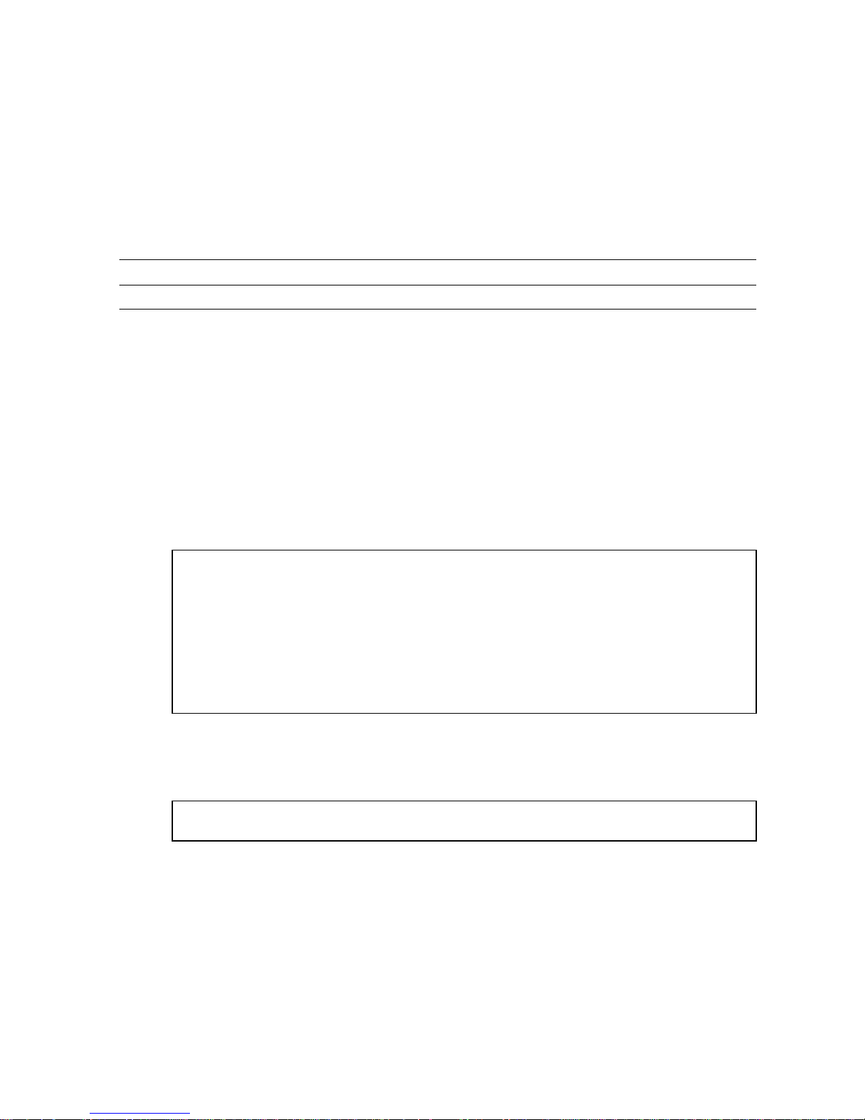
The Sun GigabitEthernet PCI adapter incorporates a new technology that transfers
data at a rate of one gigabit per second—10 times the rate of a fast Ethernet adapter.
The Sun GigabitEthernet PCI adapter targets the increased congestion experienced at
the backbone and server levels by today’s networks, while providing a future
upgrade path for high-end workstations that require more bandwidth than fast
Ethernet can provide.
FIGURE 1-1 Sun GigabitEthernet PCI Adapter
1
Page 20

Features
The Sun GigabitEthernet PCI adapter features include:
PCI
■ Full-duplex gigabit ethernet interface (IEEE P802.3z draft)
■ Standard Ethernet frame size (1518 bytes)
■ Dual Homing for automatic failover if a port, switch, or adapter is down
■ VLANs: up to 64 VLANs using IEEE 802.1Q tagging
■ Dual DMA channels
■ Adaptive interrupt frequency (maximizes network throughput depending on
traffic load)
■ ASIC with on-chip MAC and RISC processor
■ Memory support
■ Duplex SC fiber connector
■ 33-MHz, 32- or 64-bit bus master with adaptive DMA
■ Universal dual voltage signaling (3.3V and 5V)
■ PCI Local Bus Rev 2.1 compliant (6.8-inch x 4.2-inch short card)
Key Protocols and Interfaces
The Sun GigabitEthernet PCI is interoperable with existing Ethernet equipment
assuming standard Ethernet minimum and maximum frame size (64 to 1518 bytes),
frame format, and compliance with the following standards and protocols:
■ Logical Link Control (IEEE 802.2)
■ Flow Control (IEEE 802.3x)
■ SNMP (limited MIB)
■ Gigabit Ethernet (IEEE P802.3z draft)
Diagnostic Support
■ RISC runs on-board diagnostic on power-up
■ SunVTS™ diagnostic tool
2 Sun GigabitEthernet PCI Adapter 1.1 User’s Guide • March 1998
Page 21

Installing the Adapter
This section describes how to install the adapter in your system and verify the
installation.
Note – Refer to your system installation or service manual for more information.
▼ To Install the Adapter
1. Power off your system and open the system unit.
2. Attach the wrist strap’s adhesive copper strip to the metal casing of the system.
Wrap the other end twice around your wrist, with the adhesive side against your
skin.
3. Holding the PCI card by the edges, unpack it and place it on an antistatic surface.
4. Identify the slot number in which you want to insert the Sun GigabitEthernet PCI
adapter.
5. Remove the PCI filler panel from the slot that you selected.
6. Holding the PCI card by the edges, align the card edge connector with the PCI
slot. Slide the card face plate into the small slot at the end of the PCI opening.
7. Applying even pressure at both corners of the card, push the PCI card until it is
firmly seated in the slot.
8. Screw the card in place.
9. Detach the wrist strap and close the system unit.
▼ To Verify the Installation
After you have installed the Sun GigabitEthernet PCI adapter and before booting the
system, verify the installation by performing the tasks that follow. Refer to the Solaris
2.x Handbook for SMCC Peripherals manual or your Solaris documentation for detailed
instructions.
1. Power on the system, and when the banner is displayed, press the Stop-A keys to
interrupt the boot process and get to the ok prompt.
Chapter 1 Installing the Sun GigabitEthernet PCI Adapter 3
Page 22

2. Use the show-devs command to list the system devices.
/pci@1f,2000/pci12ae,1@1 identifies the Sun GigabitEthernet PCI adapter.
You should see Sun GigabitEthernet PCI adapter output similar to the example
below. The example shows the output from a Sun Ultra™ Enterprise™ 3000 If you
are using a different system, the output will be different.
ok show-devs
/SUNW,ffb@1e,0
/SUNW,UltraSPARC-II@0,0
/pci@1f,2000
/pci@1f,4000
/counter-timer@1f,1c00
/virtual-memory
/memory@0,60000000
/aliases
/options
/openprom
/chosen
/packages
/pci@1f,2000/pci12ae,1@1
/pci@1f,4000/scsi@3
/pci@1f,4000/network@1,1
/pci@1f,4000/ebus@1
/pci@1f,4000/scsi@3/tape
/pci@1f,4000/scsi@3/disk
/pci@1f,4000/ebus@1/SUNW,CS4231@14,200000
....
■ In the Sun Ultra Enterprise 3000 system, /pci@1f,2000/pci12ae,1@1
identifies the Sun GigabitEthernet PCI adapter. In the Sun Ultra 450, /
pci@6,2000/ethernet@1 and /pci@6,4000/ethernet@2 identify the Sun
GigabitEthernet PCI adapter instead of /pci@
If the PCI adapter is not listed, check that the card is properly seated and reinstall it
if necessary.
4 Sun GigabitEthernet PCI Adapter 1.1 User’s Guide • March 1998
1f,2000/pci12ae,1@1.
Page 23

Installing the Adapter Software
This section describes how to install the Sun GigabitEthernet PCI adapter software.
Note – You must have the Sun GigabitEthernet PCI Adapter installed in your
system before you install the software.
▼ To Install the Software
Note – If the CD-ROM drive that you are using for software installation is attached
to a remote machine, refer to your Solaris installation guide for remote CD-ROM
access.
1. Become superuser.
2. Check for any previously installed Sun GigabitEthernet software packages:
# pkginfo | grep SUNWvge
3. If you find any previously installed packages, remove them:
# pkgrm SUNWvge
4. Place the CD-ROM in its caddy and load the caddy into the CD-ROM drive.
5. Mount the CD-ROM on a local directory.
If Volume Manager (vold) is running on your machine, then the
CD-ROM is mounted automatically under /cdrom/sungige_1_1 when it is loaded
in the drive.
If Volume Manager (vold) is not running on your machine, create a directory called
/cdrom/sungige_1_1 and mount the CD-ROM manually.
# mkdir /cdrom/sungige_1_1
# mount -F hsfs -r /dev/sr0 /cdrom/sungige_1_1
Chapter 1 Installing the Sun GigabitEthernet PCI Adapter 5
Page 24

6. Access the package directory:
# cd /cdrom/sungige_1_1/Product
7. Check the available packages:
# pkgadd -d .
The screen displays a list of packages available for installation:
The following packages are available:
1 SUNWvge Sun GigabitEthernet Adapter 1.1
(sparc) 1.0.0
2 SUNWvts Online Validation Test Suite 2.0
(sparc) 2.1, REV=35.97.05.30
Select package(s) you wish to process (or ‘all’ to process all
packages). (default: all) [?, ??, q]
8. Press Return.
The pkgadd command starts the installation script.
9. Respond to the prompts in the script.
Note – pkgadd keeps cycling through its script once it has started. Quit the
program by typing q the second time the list of packages displays.
6 Sun GigabitEthernet PCI Adapter 1.1 User’s Guide • March 1998
Page 25

10. When you have finished loading the software, unmount the CD-ROM directory:
# cd /
# eject /cdrom
If the automounter failed to flush a previous mount point, you may see the
following directory:
/cdrom/sungige_1_1#1
If this should happen, remove the empty directory.
# rmdir /cdrom/sungige_1_1#1
11. Reboot your machine using the following command:
# reboot -- -r
If the PCI card is not installed, you will see the following messages:
drvconfig: Driver (vge) failed to attach
Warning: Driver (vge) successfully added to system but failed to attach
pkgadd: ERROR: postinstall script did not complete successfully
If this happens, install the card and reboot your machine using the following
command:
# reboot -- -r
Chapter 1 Installing the Sun GigabitEthernet PCI Adapter 7
Page 26

▼ To Set the MANPATH Environmental Variable
You must set the MANPATH environmental variable if you want the /bin/man
command to find the vge man page installed by the SUNWvge package. The file you
edit will depend on the shell you use.
● Using a Bourne or Korn shell, edit the $HOME/.profile file by adding the
following:
MANPATH=/var/opt/SUNWvge/man:$MANPATH
export MANPATH
● Using a C shell, edit the $home/.cshrc file by adding the following:
setenv MANPATH “/var/opt/SUNWvge/man:$MANPATH”
LED Indicators
TABLE 2 explains the LED indicators on the adapter.
TABLE 2 Sun GigabitEthernet PCI LEDs
Light State Description
Yellow •Off
•On
• Blinking
Green • Off
• Steady
• Flickering
• Blinking
•Connection is good
•Fault condition detected on this port, which could be the
result of a bad cable or a bad connector; or no cable is
connected to this port
•Data coming in
•Port not connected to a device
•Link detected, no data
•Link detected, data detected
•Port has been disabled by software
8 Sun GigabitEthernet PCI Adapter 1.1 User’s Guide • March 1998
Page 27

CHAPTER
2
Configuring the Sun
GigabitEthernet PCI Adapter
For proper performance, once the Sun GigabitEthernet PCI adapter software is
installed on your system, it must be configured.
Perform each of the following tasks to configure the Sun GigabitEthernet PCI
adapter.
Note – If you have moved any card from one slot to another, you must remove all
vge entries from the /etc/path_to_inst file before setting or changing any of the
configuration settings.
Configuring the Host Files
Each adapter must be assigned a host name and an IP address. If VLANs are to be
used, any specific adapter may have one host name and IP address for each VLAN
(see “To Configure VLANs” on page 22).
If you are not using multiple VLANs, follow these steps when configuring the host
name and IP address for your adapter:
1. Create the /etc/hostname.vge<num> file(s) on the server.
There can be twice the number of adapters your server normally accommodates if
they are configured for dual homing with the extra adapters in stand by mode.
One hostname.vge<num> file must be created for each adapter on the server.
Create files using the following naming format:
/etc/hostname.vge<num>
9
Page 28
For each file, the number <num> in the filename is determined according to
TABLE 2-1, which illustrates the concept using four adapters. For example, the first
adapter in the server requires a file named /etc/hostname.vge0. The second
adapter requires a file named /etc/hostname.vge1.
TABLE 2-1 Filenames for Adapters
First Adapter Second Adapter Third Adapter Fourth Adapter
/etc/hostname.vge0 /etc/hostname.vge1 /etc/hostname.vge2 /etc/hostname.vge3
2. Place the appropriate adapter host name into the hostname.vge<num> file(s).
The /etc/hostname.vge<num> file must contain the appropriate host name for
the adapter.
The host name should be different from that of any other interface. For example,
/etc/hostname.vge0 and /etc/hostname.vge1 cannot share the same host
name.
The following example depicts the host name files required for a machine called
zardoz, with four Sun GigabitEthernet adapters known as zardoz-11, zardoz12, zardoz-13, and zardoz-14 on the networks connected to the vge0, vge1,
vge2, and vge3 Ethernet devices.
zardoz # cat /etc/hostname.vge0
zardoz-11
zardoz # cat /etc/hostname.vge1
zardoz-12
zardoz # cat /etc/hostname.vge2
zardoz-13
zardoz # cat /etc/hostname.vge3
zardoz-14
3. For each host name, enter the appropriate IP address in the /etc/hosts file.
4. Reboot the system.
# reboot -- -r
If you make changes and put the system into service before rebooting, you may
experience configuration problems.
10 Sun GigabitEthernet PCI Adapter 1.1 User’s Guide • March 1998
Page 29

Configuring Driver Parameters
The ndd (1M) utility is useful for changing configuration parameters for the adapter.
Alternately, adapter parameters can be changed by manually editing the
configuration files (see “Configuring Driver Parameters Manually” on page 17). This
section describes the ndd utility in detail.
Note – Any changes made with ndd are temporary and will be lost when you
reboot the system. To make configuration changes survive the reboot process, you
will need to store driver settings in the /etc/rc2.d file (see “Saving Driver
Parameters Beyond Reboot” on page 15).
Available Parameters
To view parameters that you set using the ndd command, type:
# ndd /dev/vge ’?’
The system will return the following:
?
stat_ticks (read and write)
send_max_coalesced_bds (read and write)
recv_max_coalesced_bds (read and write)
nic_tracing (read and write)
link_negotiation (read and write)
dump_nic (read and write)
jumbo (read and write)
vlan? (read and write)
vlan_tag (read and write)
vlan_tag_id (read and write)
redund? (read and write)
redund (read and write)
fdr_filter (read and write)
instance (read and write)
Chapter 2 Configuring the Sun GigabitEthernet PCI Adapter 11
Page 30

TABLE 2-2 explains the available ndd parameters and shows the default value as well
as the minimum and maximum allowed values of each.
TABLE 2-2 Explanation of ndd Parameters
Parameter Meaning Default Minimum Maximum
stat_ticks Minimum number of 100 usec
100 0 No limit
ticks between statistics updates.
send_max_coalesced_bds Number of sends before a send
60 1 127
complete event is set.
recv_max_coalesced_bds Maximum number of receives
61 511
that can be bundled into an
event.
nic_tracing (not currently available) 0 0 No limit
link_negotiation Used to set IEEE 802.3z (draft)
Link Negotiation to auto or off.1(for auto)0(for off)
dump_nic Takes a dump of adapter
memory. A system core dump
will then include adapter
information.
0 0 (clear NIC
dump
memory,
return it to the
1
(for auto)
1 (dump
current
adapter
information)
system)
jumbo (not currently available)
vlan? (do not use; value is set by
startup file)
vlan_tag (do not use; value is set by
startup file)
vlan_tag_id (do not use; value is set by
startup file)
redund? (do not use; value is set by
startup file)
redund (do not use; value is set by
startup file)
fdr_filter Set to on if the adapter is
attached to a Full Duplex switch,
repeater, or router.
instance Used to set the device number
from which the previous data is
extracted.
12 Sun GigabitEthernet PCI Adapter 1.1 User’s Guide • March 1998
0
(for off)0(for off)
1
(for on)
0 0 # of adapters
in the system
Page 31

Checking Parameter Settings
To check a current parameter setting, use the following command:
# ndd /dev/vge <parameter_name>
▼ To Temporarily Change a Parameter
1. Check the /etc/path_to_inst file for the instance associated with particular
devices.
2. Specify the instance for the adapter you wish to configure:
# ndd -set instance <instance number>
Any subsequent ndd configuration commands will act on the adapter with the
selected instance. The adapter remains selected until you specify a different instance.
3. Specify the configuration command using the following format:
# ndd -set <parameter> <value>
Note – Any changes made with ndd will be lost when you reboot the system. To
make configuration changes survive the reboot process, you will need to store driver
settings in the /etc/rc2.d file (see “Saving Driver Parameters Beyond Reboot” on
page 15).
Increasing TCP/IP Performance
You can increase the TCP/IP performance of the Sun GigabitEthernet PCI Adapter
by changing the TCP/IP ndd values as follows:
Chapter 2 Configuring the Sun GigabitEthernet PCI Adapter 13
Page 32

● As superuser, type:
# ndd -set /dev/tcp tcp_recv_hiwat 65535
# ndd -set /dev/tcp tcp_xmit_hiwat 65535
# ndd -set /dev/tcp tcp_cwnd_max 65534
# ndd -set /dev/udp udp_recv_hiwat 65535
# ndd -set /dev/udp udp_xmit_hiwat 65535
Note – These changes are global and affect other cards in the system.
The changes will take effect immediately, and they will affect all the networking
interfaces in the system. However, the changes will be lost when you reboot your
machine.
To avoid losing these settings when you reboot, add your ndd parameter settings to
the start-up file as shown in the following section.
14 Sun GigabitEthernet PCI Adapter 1.1 User’s Guide • March 1998
Page 33

Saving Driver Parameters Beyond Reboot
Any parameter changes made using ndd will be lost the next time your system is
rebooted.
● To avoid losing the settings, put these parameter changes into a start-up file in
/etc/rc2.d, similar to the following example:
# !/sbin/sh
# Local kernel modifications
#
case “$1” in
‘start’)
echo “Setting local kernel parameters...\c”
ndd -set /dev/tcp tcp_recv_hiwat 65535
ndd -set /dev/tcp tcp_xmit_hiwat 65535
ndd -set /dev/tcp tcp_cwnd_max 65534
ndd -set /dev/udp udp_recv_hiwat 65535
ndd -set /dev/udp udp_xmit_hiwat 65535
echo””
..
“
‘stop’)
echo “0: No parameters changed.”
*)
echo “Usage: $0 {start|stop}”
..
“
esac
Chapter 2 Configuring the Sun GigabitEthernet PCI Adapter 15
Page 34

For example, if you need to set Link Negotiation “off” for adapter 2 and increase the
TCP/IP values, you could place the following lines in the /ect/rc2.d start-up file:
# !/sbin/sh
# Local kernel modifications
#
case “$1” in
‘start’)
echo “Setting local kernel parameters...\c”
ndd -set instance 2
ndd -set link_negotiation 0
ndd -set /dev/tcp tcp_recv_hiwat 65535
ndd -set /dev/tcp tcp_xmit_hiwat 65535
ndd -set /dev/tcp tcp_cwnd_max 65534
ndd -set /dev/udp udp_recv_hiwat 65535
ndd -set /dev/udp udp_xmit_hiwat 65535
echo””
..
“
‘stop’)
echo “$0: No parameters changed.”
*)
echo “Usage: $0 {start|stop}”
..
“
esac
Capturing Dump Information
The dump_nic command should be used if an adapter stops operating for any
reason. The dump contains internal adapter state information which can be used to
troubleshoot problems.
To take a dump of an adapter’s state information, once the adapter has stopped
operating:
1. Select the proper adapter instance.
# ndd -set /dev/vge instance <value>
2. Set the adapter to dump state information in the case of a system core dump.
# ndd -set /dev/vge dump_nic 1
16 Sun GigabitEthernet PCI Adapter 1.1 User’s Guide • March 1998
Page 35

3. To verify this function, force the system to take a core dump. At the ok prompt,
type:
ok sync
This will reboot the system and save the adapter memory information into a file.
4. Go to the /var/crash/hostname directory and check for the dump information:
% cd /var/crash/<hostname>
% ls
The dump information will be under one of the following file names: bounds,
unix.0,orvmcore.0.
5. Use a text editor to open the file containing the dump information.
Configuring Driver Parameters
Manually
The vge device driver controls the pci12ae,1 Ethernet device.
You can manually configure the vge device driver parameters to customize each
pci12ae,1 device in your system:
■ Configure the vge driver parameters generally for all pci12ae,1 devices in the
system by entering the parameter variables in the /etc/system file.
■ Set a parameter on a per-device basis by creating the vge.conf file in the
/kernel/drv directory.
Chapter 2 Configuring the Sun GigabitEthernet PCI Adapter 17
Page 36

Autonegotiation
The default configuration for autonegotiation of the Gigabit Ethernet link is auto.
With this setting the Sun GigabitEthernet PCI adapter will use IEEE 802.3z (draft)
autonegotiation. All Sun GigabitEthernet adapters and SunSwitches have auto
negotiation set to auto as the default configuration.
If you are connecting the adapter to Gigabit Ethernet equipment that does not
support autonegotiation, or if there is a problem establishing a link between the two
devices, autonegotiation can be turned off (see
are set to the same speed and duplex configuration.
Note – Autonegotiation has changed in the most recent version of the IEEE 802.3z
(draft). Release 1.0 software for the Sun GigabitEthernet adapters and SunSwitch uses
a different version of auto negotiation than Release 1.1. If you are trying to connect a
Release 1.0 device to a Release 1.1 device, you can choose to upgrade and run Release
1.1 on both devices or turn autonegotiation off on both devices.
TABLE 2-2). Be sure that both devices
18 Sun GigabitEthernet PCI Adapter 1.1 User’s Guide • March 1998
Page 37

CHAPTER
3
Optional Configurations
Your Sun GigabitEthernet PCI adapter can be configured to support the following
options:
■ VLANs: Virtual Local Area Networks (VLANs) are commonly used to split up
groups of network users into manageable broadcast domains, to create logical
segmentation of workgroups, and to enforce security policies among each logical
segment.
have a logical presence on multiple IP subnets. Up to 64 VLANs can be defined for
each Sun GigabitEthernet PCI adapter on your server.
■ Dual Homing: Two Sun GigabitEthernet adapters on a server can be paired for
redundant operation through the use of the Dual Homing feature. If traffic on a
primary connection is lost due to the failure of the adapter, cable, switch port, or
switch (when the dual adapters are attached to separate switches), the secondary
adapter becomes active and assumes the MAC and IP address of the primary
adapter. Network sessions should be maintained after the switch-over, causing
the minimum impact to the user.
With multiple VLANs on an adapter, a server with a single adapter can
If your network does not require multiple VLANs or Dual Homing, you may use the
default configuration, in which case no further configuration is necessary.
The following sections explain these options in detail, and provide configuration
instructions and examples for each.
Note – If you change any of the optional configuration parameters (VLAN or Dual
Homing), you must reboot the system before the changes will take effect. If you
make changes and do not reboot, you may experience configuration problems.
19
Page 38

An Overview of VLANs
VLANs allow you to split your physical LAN into logical subparts, providing an
essential tool for increasing the efficiency and flexibility of your network.
VLANs are commonly used to separate groups of network users into manageable
broadcast domains, to create logical segmentation of workgroups, and to enforce
security policies among each logical segment. Each defined VLAN behaves as its
own separate network, with its traffic and broadcasts isolated from the others,
increasing the bandwidth efficiency within each logical group.
Although VLANs are commonly used to create individual broadcast domains and/
or separate IP subnets, it is sometimes useful for a server to have a presence on more
than one VLAN simultaneously. Sun GigabitEthernet adapters and SunSwitch
products support multiple VLANs on a per port or per interface basis, allowing very
flexible network configurations.
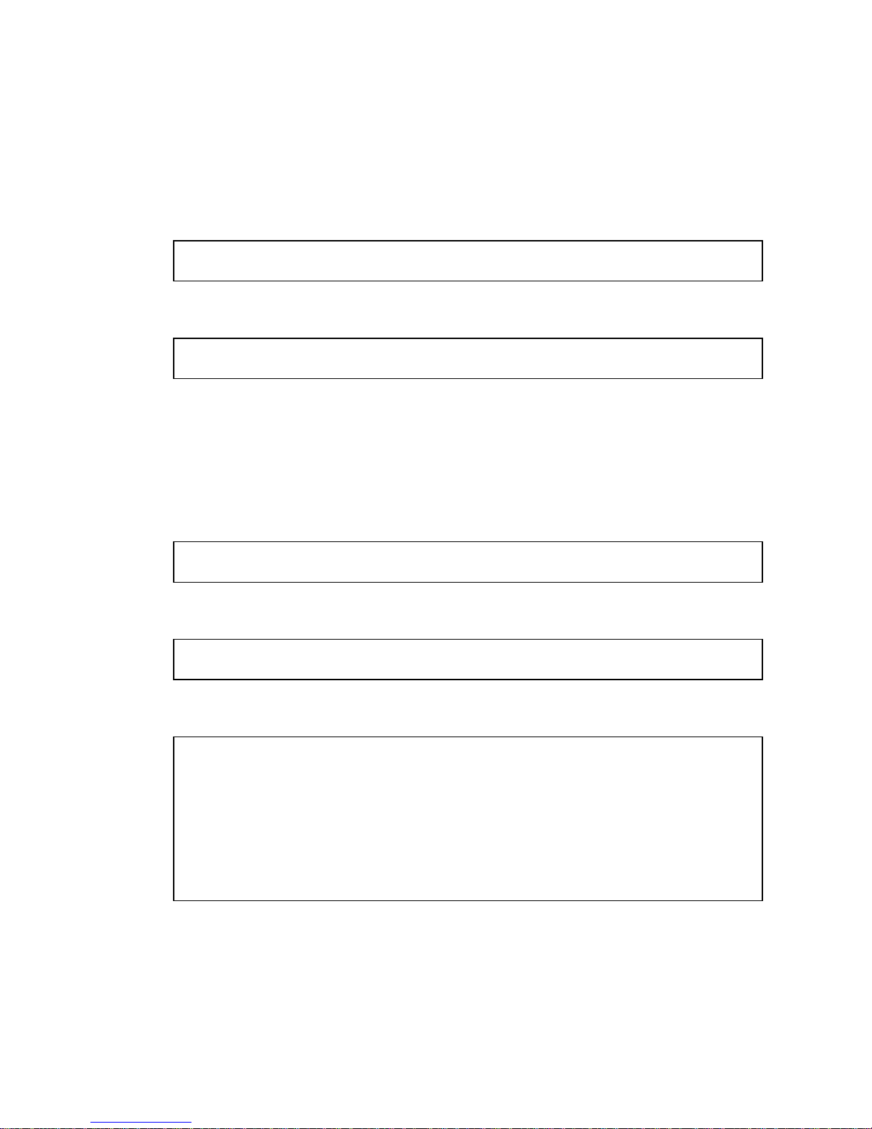
FIGURE 3-1 shows an example network that uses VLANs.
VLAN 1
VLAN 2
VLAN 3
Shared Media Segment
Software
PC 1
(VLAN 2)
Software
PC 2
(VLAN 2)
Accounting
Server
(VLAN 3)
12345678
10/100 Base - TX Gigabit Ethernet
12345678
Engineering
PC 3
(VLAN 1)
9
Accounting
PC 4
(VLAN 3)
Main Server
Adapter
Gigabit/Tagged
(All VLANs)
Engineering/
Software PC 5
Adapter
Gigabit/Tagged
(VLAN 1 & 2)
FIGURE 3-1 Example of Servers Supporting Multiple VLANs with Tagging Adapters
20 Sun GigabitEthernet PCI Adapter 1.1 User’s Guide • March 1998
Page 39

The example network has the following features:
■ The physical LAN network consists of a switch, two servers, and five clients.
■ The LAN is logically organized into three different VLANs, each representing a
different IP subnet.
■ VLAN 1 is an IP subnet consisting of the Main Server, Client 3, and Client 5. This
represents an engineering group.
■ VLAN 2 includes the Main Server, Clients 1 and 2 via shared media segment, and
Client 5. This is a software development group.
■ VLAN 3 includes the Main Server, the Accounting Server and Client 4. This is an
accounting group.
■ The Main Server is a high-use server that needs to be accessed from all VLANs
and IP subnets. The server has an Sun GigabitEthernet adapter installed. All three
IP subnets are accessed via the single physical adapter interface. The server is
attached to one of the SunSwitch’s Gigabit Ethernet ports, which is configured for
VLANs 1, 2, and 3. Both the adapter and the connected SunSwitch port have
tagging turned on. Because of the tagging VLAN capabilities of both devices, the
sever is able to communicate on all three IP subnets in this network, but continues
to maintain broadcast separation between all of them.
■ The Accounting Server is available to VLAN 3 only. It is isolated from all traffic
on VLANs 1 and 2. The switch port connected to the server has tagging turned
off.
■ Clients 1 and 2 are attached to a shared media hub that is then connected to the
switch. They belong to VLAN 2 only, and are logically in the same IP subnet as
the Main Server and Client 5. The switch port connected to this segment has
tagging turned off.
■ Client 3 is a member of VLAN 1, and can communicate only with the Main Server
and Client 5. Tagging is not enabled on Client 3’s switch port.
■ Client 4 is a member of VLAN 3, and can communicate only with the servers.
Tagging is not enabled on Client 4’s switch port.
■ Client 5 is a member of both VLANs 1 and 2, and has a Sun GigabitEthernet
adapter installed. It is connected to switch port 10. Both the adapter and the
switch port are configured for VLANs 1 and 2 and have tagging enabled.
VLAN tagging is only required to be enabled on switch ports that create trunk links to
other SunSwitches, or on ports connected to tag-capable end-stations, such as servers or
workstations with Sun GigabitEthernet adapters.
Chapter 3 Optional Configurations 21
Page 40

▼ To Configure VLANs
By default, the SunSwitch has a single VLAN configured for every port, which
groups all ports into the same broadcast domain, just as if there were no VLANs at
all. This default VLAN has an 802.1Q VLAN identification number of [1], with
VLAN tagging for the switch port turned off.
Follow these steps when configuring VLANs:
Note – If you configure a VLAN for an adapter, all traffic sent or received by that
adapter must be in VLANs.
1. Create the /etc/hostname.vge file(s) on the server.
There can be twice the number of adapters your server normally accommodates if
they are configured for dual homing and the extra adapters are in stand by mode.
You can configure up to 64 VLANs defined for each adapter in active mode.
One hostname.vge<num> file must be created for each VLAN which will be
configured for each adapter on the server. Create files using the following naming
format:
/etc/hostname.vge<num>
For each file, the number <num> in the filename is determined according to
For example, the first adapter in the server requires a file named /etc/
hostname.vge0 for its first VLAN, and a file named /etc/hostname.vge100 for
its second VLAN.
TABLE 3-1 Naming Convention for Adapters Configured for VLANs
Up to
64
VLANs
per
adapter First Adapter Second Adapter Third Adapter Fourth Adapter
/etc/hostname.vge0 /etc/hostname.vge1 /etc/hostname.vge2 /etc/hostname.vge3
1
/etc/hostname.vge100 /etc/hostname.vge101 /etc/hostname.vge102 /etc/hostname.vge103
2
/etc/hostname.vge200 /etc/hostname.vge201 /etc/hostname.vge202 /etc/hostname.vge203
3
...
64
/etc/hostname.vge6300 /etc/hostname.vge6301 /etc/hostname.vge6302 /etc/hostname.vge6303
TABLE 3-1.
22 Sun GigabitEthernet PCI Adapter 1.1 User’s Guide • March 1998
Page 41

2. Place the appropriate adapter host name into the hostname.vge file(s).
The /etc/hostname.vge<num> file must contain the appropriate host name for
the adapter.
The host name should be different from the host name of any other interface. For
example, /etc/hostname.vge0 and /etc/hostname.vge1 cannot share the same
host name.
The following example depicts the host name files required for a machine called
zardoz, with four adapters known as zardoz-11, zardoz-12, zardoz-13, and
zardoz-14 on the networks connected to the vge0, vge1, vge2, and vge3 Ethernet
devices.
zardoz # cat /etc/hostname.vge0
zardoz-11
zardoz # cat /etc/hostname.vge1
zardoz-12
zardoz # cat /etc/hostname.vge2
zardoz-13
zardoz # cat /etc/hostname.vge3
zardoz-14
3. For each host name, enter the appropriate IP address in the /etc/hosts file.
4. Create the /etc/vlan.vge<num> file(s).
One corresponding vlan.vge<num> file is needed for each /etc/
hostname.vge<num> file created in the previous steps (one for each VLAN being
configured for each adapter on the server). Create files using the following naming
format:
/etc/vlan.vge
<num>
For each file, the number <num> in the filename is determined according to
TABLE 3-2. For example, the first adapter requires a file named /etc/vlan.vge0 for
its first VLAN, and a file named /etc/vlan.vge100 for its second VLAN.
TABLE 3-2 Naming Convention for VLAN Files
Up to 64
VLANs per
Adapter First Adapter Second Adapter Third Adapter Fourth Adapter
1
2
/etc/vlan.vge0 /etc/vlan.vge1 /etc/vlan.vge2 /etc/vlan.vge3
/etc/vlan.vge100 /etc/vlan.vge101 /etc/vlan.vge102 /etc/vlan.vge103
Chapter 3 Optional Configurations 23
Page 42

TABLE 3-2 Naming Convention for VLAN Files (Continued)
Up to 64
VLANs per
Adapter First Adapter Second Adapter Third Adapter Fourth Adapter
3
...
64
/etc/vlan.vge200 /etc/vlan.vge201 /etc/vlan.vge202 /etc/vlan.vge203
/etc/vlan.vge6300 /etc/vlan.vge6301 /etc/vlan.vge6302 /etc/vlan.vge6303
5. Place the appropriate VLAN ID tag into the vlan.vge<num> file(s).
Each VLAN must be assigned a unique identification number. Even though the
maximum number of VLANs that can be configured on each adapter is 64, any
particular VLAN can be assigned an identification number between 1 and 4094. The
VLAN tagging format follows the guidance provided in IEEE 802.1Q (Draft 5).
The VLAN identifier numbers must be placed into each appropriate
vlan.vge<num> file to which the adapter is a member.
Example: Consider a server with a single adapter. The server is a member of two
VLANs, with VLAN identifiers 383 and 777. The contents of the first file, /etc/
vlan.vge0, would be 383 and the contents of the second file, /etc/vlan.vge100,
would be 777.
Use your regular text editor to put the VLAN identifier number into the appropriate
vlan.vge<num> file. Be certain that there are no spaces, blank lines, or extra
characters. The identifier can be entered in decimal (e.g. 383), octal (e.g. 0577), or
hexadecimal (e.g. 0x17F) format.
6. If you are finished with all optional configuration, reboot the system.:
# reboot -- -r
Changes to the optional configuration parameters (VLAN or Dual Homing) do not
take effect until you reboot the system. If you will be making changes to the other
optional parameters during your configuration session, you may wait to reboot until
those changes are complete.
If you make changes and put the system into service before rebooting, you may
experience configuration problems.
24 Sun GigabitEthernet PCI Adapter 1.1 User’s Guide • March 1998
Page 43

An Overview of Dual Homing
When two Sun GigabitEthernet adapters are installed in the same server, they can be
paired in a Dual Homing configuration. If traffic is not seen over the primary
adapter connection due to loss of the adapter, cable, switch port, or switch (where
the two adapters are attached to separate switches), the secondary adapter becomes
active. When it becomes active, the secondary adapter uses the MAC and IP address
originally assigned to the primary adapter. Sessions should be maintained, causing
minimum impact to the user.
The Dual Homing feature requires that Spanning Tree Protocol be enabled. Adapters
configured for Dual Homing allow Spanning Tree Protocol packets to pass between
them. This causes the Spanning Tree Protocol to detect a loop in the network, forcing
the switch port connected to one of the adapters to go into blocking mode. The
blocked adapter becomes the secondary.
Server Switch
#1
#2
Both Connections Ready
Spanning Tree Loop Detected:
Adapter #1 is active
Adapter #2 is blocked at switch port
Server Switch
#1
#2
Primary Connection Failed
Loop resolved:
Adapter #1 has dropped from loop
Adapter #2 is active
If the primary connection becomes disabled for any reason, the Spanning Tree
Protocol will detect the loss of the loop, and will change the switch port connecting
the secondary adapter from blocking mode to forwarding mode.
▼ To Configure Dual Homing
To set up a Dual Homing configuration in a system with two adapters, where
adapter etc/hostname.vge0 is primary and etc/hostname.vge1 is secondary,
enter the following:
1. Enable Spanning Tree Protocol on the switch connected to your adapters.
Chapter 3 Optional Configurations 25
Page 44

2. The port to which the secondary adapter is connected must be the port that blocks.
If there is more than one switch in the spanning tree, be certain that the secondary
adapter is not attached to the root switch of the spanning tree. Also, be sure that the
port path cost of the switch port connected to the secondary adapter is higher than
the other ports in the loop.
For example, in the following redundant switch configuration, the switch port
connected to adapter #2 must have the highest port path cost of any of the four ports
in the loop:
Inter-switch path
required for loop
condition
12345678
12345678
10/100 Base - TX Gigabit Ethernet
Loop ports need
lower path cost
Port to active adapter
needs lower path cost
9
Server
#1
#2
12345678
12345678
10/100 Base - TX Gigabit Ethernet
9
Port to secondary
adapter must have
highest path cost
to block
3. Create the /etc/redund.vge1 file.
4. Use your regular text editor to put the number 0, the instance number of the
primary adapter, into the file /etc/redund.vge1.
Put the number 0 in the file, without spaces or blank lines.
Note – Do not configure an /etc/hostname.vge<num> entry for a redundant adapter.
Do not configure VLAN support for the secondary adapter in a Dual Homing
configuration. If the secondary adapter becomes primary, it takes on the
configuration of the primary adapter. Serious configuration problems will occur if
there are VLAN configuration files for the secondary adapter.
26 Sun GigabitEthernet PCI Adapter 1.1 User’s Guide • March 1998
Page 45

APPENDIX
A
Quick Installation Instructions
This appendix provides an overview of what you must do to install and configure
the Sun Gigabit Ethernet PCI Adapter quickly and easily, without VLAN or Dual
Homing features. All configurations can be changed at any time.
▼ To Install the Adapter
1. Shutdown and power off the system that will receive the adapter(s).
2. Install Gigabit Ethernet adapter into appropriate slot(s) within your system.
3. Power on the system and watch for the Gigabit adapter device information to be
displayed on the system console. If you don’t see the adapter, you may need to
repeat step 1 to ensure that the adapter has been properly seated.
27
Page 46
▼ To Install the Software
1. Become root.
2. Check for any previously installed Sun GigabitEthernet software packages:
# pkginfo | grep SUNWvge
3. If you find any previously installed packages, remove them:
# pkgrm SUNWvge
4. Place the CD-ROM into the CD-ROM drive.
5. Mount the CD-ROM on a local directory.
If the Volume Manager (vold) is running, on your machine, then the CD-ROM is
mounted automatically under /cdrom/sungige_1_1 when it is loaded in the drive
6. Access the package directory.
# cd /cdrom/sungige_1_1/Product
7. Install the software by entering pkgadd -d . (don’t forget the dot):
# pkgadd -d .
The screen displays a list of packages available for installation:
The following packages are available:
1 SUNWvge Sun GigabitEthernet Adapter 1.1
(sparc) 1.0.0
2 SUNWvts Online Validation Test Suite 2.0
(sparc) 2.1, REV=35.97.05.30
Select package(s) you wish to process (or ‘all’ to process all
packages). (default: all) [?, ??, q]
8. Press Return.
The pkgadd command starts the installation script.
9. Respond to the prompts in the script.
28 Sun GigabitEthernet PCI Adapter 1.1 User’s Guide • March 1998
Page 47
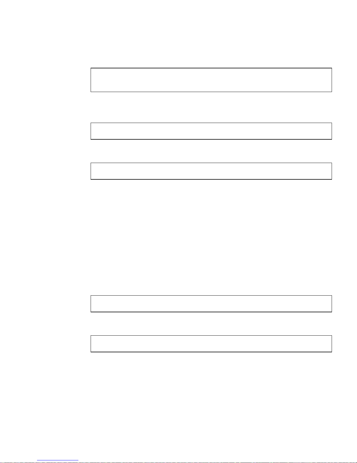
10. When you have finished loading the software, unmount the CD-ROM directory:
# cd /
# eject /cdrom
If the automounter fails to flush a previous mount point, you may see the following
directory:
/cdrom/sungige_1_1#1
If this should happen, remove the empty directory.
# rmdir /cdrom/sungige_1_1#1
▼ Configure the Host Files
1. Enter echo <interface-name>/etc/hostname.vge0.
The variable <interface-name> represents the name to be associated with the first
gigabit ethernet adapter (for example,
echo myhostname-ge0 /etc/hostname.vge0)
2. Assign the IP address by using vi or a similar text editor to edit the /etc/hosts
file.
For the example in Step 1, to assign the IP address 192.170.87.32 to the interface
myhostname-ge0, you would add the following entry to your /etc/hosts file:
192.170.87.32 myhostname-ge0
3. Reboot your system.
# reboot -- -r
Appendix A Quick Installation Instructions 29
Page 48

30 Sun GigabitEthernet PCI Adapter 1.1 User’s Guide • March 1998
Page 49

APPENDIX
B
SunVTS Diagnostic Software
This appendix contains an overview of the SunVTS™diagnostic tool/application.
The SunVTS software executes multiple diagnostic hardware tests from a single user
interface and is used to verify configuration and functionality of most hardware
controllers and devices. SunVTS operates primarily from the OpenWindows
interface, enabling test parameters to be set quickly and easily while a diagnostic test
operation is being performed.
The nettest diagnostic test checks all the networking interfaces on a system,
including the Sun GigabitEthernet PCI adapter.
™
user
To use the nettest diagnostic, you must have the SunVTS software installed on
your system.
Note – You must have Classical IP up and running on an interface for the nettest
diagnostic test to work.
Refer to the SunVTS User’s Guide for more information on how to run the nettest
diagnostic test.
The SunVTS documents are listed in
information about SunVTS. These documents are available on the Solaris on Sun
Hardware AnswerBook. The Solaris on Sun Hardware AnswerBook is provided on the
SMCC Updates CD for the Solaris release on your system.
TABLE B-1. Refer to them for detailed
31
Page 50

TABLE B-1 SunVTS Documentation
Title Part Number Description
SunVTS User’s Guide 802-5331 Describes the SunVTS environment;
starting and controlling various user
interfaces
SunVTS Test Reference Manual 802-5330 Describes each SunVTS test;
provides various test options and
command-line arguments
SunVTS Quick Reference Card 802-5329 Provides overview of vtsui
interface features
The main features of the SunVTS environment include:
■ SunVTS kernel
The SunVTS kernel (vtsk) diagnostic tool controls all testing and operates in the
OpenWindows background. When activated, vtsk probes the hardware
configuration of the system tested and responds to vtsui. vtsk coordinates
execution of individual tests and manages the messages sent by these tests.
■ SunVTS user interface
The SunVTS user interface (vtsui) diagnostic tool operates in the OpenWindows
background. Upon activation, vtsui provides vtsk control, various user
options, tests, and read-log files.
■ SunVTS TTY
The vtstty diagnostic tool controls the vtsk from either a command shell or a
terminal attached to a serial port. Most options available in vtstty have
equivalent options in vtsui. vtstty is applicable to server configurations only.
32 Sun GigabitEthernet PCI Adapter 1.1 User’s Guide • March 1998
Page 51

APPENDIX
C
Sun GigabitEthernet PCI
Adapter Connectors
FIGURE C-1 shows the connector for the Sun GigabitEthernet PCI adapter.
FIGURE C-1 Connector for the Sun GigabitEthernet PCI Adapter
TABLE C-1 lists the characteristics of the 1000 Base-SX link.
TABLE C-1 1000BASE-SX Link Characteristics (IEEE P802.3z draft)
Description 62.5 Micron 50 Micron Unit
Shortwave (850 nm multimode fiber)
Operating Range 2 to 260 meters 2 to 550 meters m
33
Page 52

Purchasing Fiber Cables
You can purchase fiber cables directly from Sun Microsystems, Inc. using the
following part numbers:
■ 2-meter fiber cable X973A
■ 15-meter fiber cable X978A
34 Sun GigabitEthernet PCI Adapter 1.1 User’s Guide • March 1998
Page 53

APPENDIX
D
Specifications
Performance Specifications
Feature Specification
PCI clock 33 MHz max
PCI data burst transfer rate up to 64-byte bursts
PCI data/address width 64-bit data/32-bit address
PCI modes Master/slave
1000BASE-SX 1000 Mbps (full duplex)
35
Page 54

Physical Characteristics
Dimension Measurement
Length 6.87 inches
Width 4.25 inches
Power Requirements
Specification Measurement
Maximum power consumption 7.5 watts
Voltage 5V
+5%
36 Sun GigabitEthernet PCI Adapter 1.1 User’s Guide • March 1998
Page 55

Environmental Specifications
Condition Operating Specification Storage Specification
Temperature 0˚ to 55˚C (+32 to +131˚F) -40˚ to +70˚C
Relative humidity 5 to 85% non-condensing
(40˚C, 16 hour dwells at
extremes)
Altitude up to 10,000 feet up to 35,000 feet
Shock 10g, 1/2 sine wave, 11 msec 60g, 1/2 sine wave, 11 msec
Vibration, peak-to-peak
displacement
Vibration, peak
acceleration
0.005 in. max (5 to 32 Hz) 0.1 in. max (5 to 17 Hz)
0.25g (5 to 500 Hz)
(sweep rate = 1 octave/min.)
5 to 95% non-condensing
10˚C/hour
0.25g (5 to 500 Hz)
(sweep rate = 1 octave/min.)
Appendix D Specifications 37
Page 56

38 Sun GigabitEthernet PCI Adapter 1.1 User’s Guide • March 1998
 Loading...