

Page 1

Sun™GigaSwift Ethernet
Adapter Installation and
User’s Guide
Sun Microsystems, Inc.
www.sun.com
Part No. 817-4341-10
August 2004, Revision A
Submit comments about this document at: http://www.sun.com/hwdocs/feedback
Page 2

Copyright 2004Sun Microsystems, Inc.,4150 NetworkCircle, Santa Clara, California 95054, U.S.A. All rights reserved.
Sun Microsystems, Inc.has intellectualproperty rights relating to technologythat isdescribed inthis document.In particular, and without
limitation, these intellectual property rightsmay includeone or more of the U.S. patents listed at http://www.sun.com/patentsand one or
moreadditional patentsor pendingpatent applicationsin theU.S. and in other countries.
This document and the productto whichit pertainsare distributed under licenses restrictingtheir use,copying, distribution,and
decompilation. No part of the product orof thisdocument maybe reproduced inany formby anymeans withoutprior writtenauthorization of
Sun and its licensors, if any.
The Energy Starlogo isa registeredtrademark of EPA.Third-party software, including font technology,is copyrighted and licensed from Sun
suppliers. Parts of the productmay bederived from Berkeley BSD systems, licensed fromthe Universityof California.UNIX isa registered
trademark in the U.S. and in other countries, exclusively licensed throughX/Open Company,Ltd.
Sun, Sun Microsystems,the Sunlogo, AnswerBook2,docs.sun.com, SunVTS, OpenBoot, SunSwitch,Sun Blade, Sun Fire, Ultra, Sun Enterprise,
Ultra Enterprise, and Solaris aretrademarks, registeredtrademarks,or servicemarks ofSun Microsystems,Inc. in the U.S. and other countries.
All SPARCtrademarks are usedunder licenseand aretrademarks or registeredtrademarks ofSPARCInternational,Inc. inthe U.S.and other
countries. Products bearingSPARCtrademarksare based upon an architecturedeveloped bySun Microsystems,Inc. Energy StarLogo® isa
registeredtrademark of EPA. As an Energy Star®Partner,Sun Microsystems, Inc.has determinedthat thisproduct meets the Energy Star(R)
guidelines for energyefficiency.
All SPARCtrademarks are usedunder licenseand aretrademarks or registeredtrademarks ofSPARCInternational,Inc. inthe U.S.and inother
countries. Products bearingSPARCtrademarksare based upon an architecturedeveloped bySun Microsystems,Inc.
The OPEN LOOK and Sun™ Graphical User Interface was developed by Sun Microsystems,Inc. for its users and licensees. Sun acknowledges
the pioneering effortsof Xeroxin researching and developing the concept of visual or graphical user interfaces for the computer industry.Sun
holds a non-exclusive license fromXerox to the Xerox GraphicalUser Interface,which licensealso coversSun’s licenseeswho implementOPEN
LOOK GUIs and otherwise comply with Sun’s written license agreements.
Sun Microsystems is an ENERGY STAR partner. Those configurations of this product
that bear the ENERGY STAR mark meet or exceed the ENERGY STAR guidelines.
ENERGY STAR
U.S. Government Rights—Commercialuse. Governmentusers aresubject to the Sun Microsystems,Inc. standardlicense agreement and
applicable provisions ofthe FARand itssupplements.
DOCUMENTATIONISPROVIDED "AS IS" AND ALL EXPRESS OR IMPLIED CONDITIONS, REPRESENTATIONSANDWARRANTIES,INCLUDING
ANY IMPLIED WARRANTY OF MERCHANTABILITY, FITNESS FOR A PARTICULAR PURPOSE OR NON-INFRINGEMENT, ARE DISCLAIMED,
EXCEPT TO THE EXTENT THAT SUCH DISCLAIMERS ARE HELD TO BE LEGALLY INVALID.
Copyright 2004 Sun Microsystems, Inc.,4150 NetworkCircle, Santa Clara, Californie 95054, Etats-Unis. Tous droits réservés.
Sun Microsystems, Inc.a lesdroits de propriété intellectuels relatantsà la technologie qui est décrit dans ce document. En particulier,et sans la
limitation, ces droitsde propriétéintellectuels peuvent inclureun ouplus desbrevets américains énumérés à http://www.sun.com/patentset
un ou les brevets plussupplémentaires ou les applications de brevet enattente dansles Etats-Uniset dansles autrespays.
Ce produit oudocument estprotégé par un copyright et distribué avec des licences qui en restreignent l’utilisation, la copie, la distribution, et la
décompilation. Aucune partie de ce produit oudocument nepeut êtrereproduitesous aucune forme, par quelque moyen que ce soit, sans
l’autorisation préalable et écrite de Sun et de ses bailleurs de licence, s’il y en a.
Le logiciel détenu par des tiers, et qui comprendla technologierelative aux polices de caractères,est protégépar un copyright et licencié par des
fournisseurs de Sun. Des parties de ce produit pourrontêtredérivées dessystèmes BerkeleyBSD licenciéspar l’Universitéde Californie.UNIX
est une marquedéposée auxEtats-Unis etdans d’autrespays et licenciée exclusivement par X/Open Company, Ltd.
Sun, Sun Microsystems,le logoSun, AnswerBook2,docs.sun.com, SunVTS,OpenBoot, SunSwitch, Sun Blade, Sun Fire, Ultra, Sun Enterprise,
Ultra Enterprise, et Solaris sont des marquesde fabrique ou desmarques déposées, ou marques deservice, deSun Microsystems,Inc. aux EtatsUnis et dans d’autres pays.Touteslesmarques SPARCsont utilisées sous licence et sont des marques de fabrique ou des marques déposées de
SPARCInternational, Inc.aux Etats-Uniset dans d’autres pays.Les produitsportant les marques SPARCsont basés sur une architecture
développée par Sun Microsystems, Inc.
Toutesles marquesSPARCsontutilisées sous licence et sont des marques de fabrique ou des marques déposéesde SPARC International, Inc.
aux Etats-Unis et dans d’autrespays. Lesproduits portant les marques SPARCsont baséssur unearchitecturedéveloppée parSun
Microsystems,Inc.
L’interfaced’utilisationgraphique OPEN LOOK et Sun™ a été développée par Sun Microsystems, Inc. pour ses utilisateurs et licenciés. Sun
reconnaîtles effortsde pionniers de Xerox pourla rechercheet le développement du concept des interfaces d’utilisation visuelle ou graphique
pour l’industrie de l’informatique. Sun détient une license non exclusive de Xerox surl’interface d’utilisation graphique Xerox, cette licence
couvrantégalement les licenciées de Sunqui mettent en place l’interfaced ’utilisation graphique OPEN LOOKet qui en outre se conforment aux
licences écrites de Sun.
LA DOCUMENTATION EST FOURNIE "EN L’ÉTAT" ET TOUTES AUTRES CONDITIONS, DECLARATIONS ET GARANTIES EXPRESSES OU
TACITES SONT FORMELLEMENT EXCLUES, DANS LA MESURE AUTORISEE PAR LA LOI APPLICABLE, Y COMPRIS NOTAMMENT TOUTE
GARANTIE IMPLICITE RELATIVE A LA QUALITE MARCHANDE, A L’APTITUDE A UNE UTILISATION PARTICULIERE OU A L’ABSENCE DE
CONTREFAÇON.
Please
Recycle
Page 3

Contents
Preface xix
1. Sun GigaSwift Ethernet Adapter Overview 1
Hardware Overview 1
Sun GigaSwift Ethernet MMF Adapter 1
LED Displays on the MMF Adapter 2
Sun GigaSwift Ethernet UTP Adapter 2
LED Displays on the UTP Adapter 3
Hardware and Software Requirements 4
Patch Requirements 4
Product Features 5
Key Protocols and Interfaces 5
Diagnostic Support 6
Support for Solaris 9 x86 Operating System 6
2. Installing the Adapter 7
Installing the Adapter With Dynamic Reconfiguration 7
Installing the Adapter Without Dynamic Reconfiguration 8
▼ To Install the Adapter 8
▼ To Verify the Hardware Installation 9
iii
Page 4

Setting the local-mac-address? Variable 13
Rebooting the System 14
Using the Installation Script 14
▼ To Install the Software Using the Installation Script 15
Verifying the Software Installation 21
Configuring the Network Host Files 22
3. Network Configuration 25
Configuring the Network Host Files 25
Setting Up a GigaSwift Ethernet Network on a Diskless Client System 27
▼ To Set Up a GigaSwift Ethernet Port on a Diskless Client 27
Installing the Solaris Operating System Over a GigaSwift Ethernet Network 28
▼ To Install the Solaris Operating System Over a GigaSwift Ethernet
Network 29
Booting Over the GigaSwift Ethernet Network 32
4. Configuring Driver Parameters 37
GigaSwift Ethernet Device Driver Parameters 37
GigaSwift Ethernet Driver Parameter Values and Definitions 38
Operational Mode Parameters 39
Flow Control Parameters 40
Gigabit Link Clock Mastership Controls 41
Interpacket Gap Parameters 41
Interrupt Parameters 43
Random Early Drop Parameters 43
PCI Bus Interface Parameters 44
Jumbo Frames 45
Setting ce Driver Parameters 46
Setting Parameters Using the ndd Utility 47
▼ To Specify Device Instances for the ndd Utility 47
iv Sun GigaSwift Ethernet Adapter Installation and User’s Guide • August 2004
Page 5

Setting Parameters Using the ce.conf File 50
▼ To Set Driver Parameters Using a ce.conf File 51
Usability Enhancements to the Driver 52
GigaSwift Ethernet Driver Operating Statistics 54
Reporting the Link Partner Capabilities 55
5. Configuring VLANs 63
Overview of VLANs 63
Configuring VLANs 66
▼ To Configure Static VLANs 67
A. Installing the Software Manually 69
Installing the Driver Software Manually 69
▼ To Install the Driver Software Manually 69
Verifying Patches 74
▼ To Install Patches 74
▼ To Install a Sun VLAN Utility Patch 76
B. Using the Sun GigaSwift Ethernet Driver in Solaris 9 x86 Operating Systems
79
Hardware and Software Requirements 79
Patch Requirements 80
Product Features 80
Key Protocols and Interfaces 80
Features Not Currently Supported 81
Using the Installation Script 81
▼ To Install the Software Using the Installation Script 81
Installing the Software Manually 84
▼ To Install the Software Manually 84
Verifying the Software Installation 87
Contents v
Page 6

Configuring Driver Parameters 87
Configuring VLANs 87
C. Specifications 89
Connectors 89
Performance Specifications 91
Physical Characteristics 91
Power Requirements 91
D. Diagnostic Software and Troubleshooting Issues 93
SunVTS Diagnostic Software 93
Using the SunVTS netlbtest 94
▼ To Use the netlbtest 94
Using the OpenBoot PROM FCode Self-Test 95
▼ To Run the FCode Self-Test Diagnostic 95
Troubleshooting Issues 98
Known Incompatibilities With Pre-IEEE 802.3z Network Switches 98
▼ To Set Autonegotiation to off for a SunSwitch or an Alteon ACE 110
Switch 98
▼ To Set Autonegotiation to off for Other Noncompliant Network
Equipment 100
Failure to Configure GigaSwift Ethernet Instance 100
Nonspecific Issues 101
Problem With DR Attach on Sun Enterprise Platforms 102
Index 103
vi Sun GigaSwift Ethernet Adapter Installation and User’s Guide • August 2004
Page 7

Figures
FIGURE 1-1 Sun GigaSwift Ethernet MMF Adapter 2
FIGURE 1-2 Sun GigaSwift Ethernet UTP Adapter 3
FIGURE 5-2 Ethernet Tag Header Format 66
FIGURE C-1 Sun GigaSwift Ethernet MMF Adapter Connector 89
FIGURE C-2 Sun GigaSwift Ethernet UTP Adapter Connector 90
vii
Page 8

viii Sun GigaSwift Ethernet Adapter Installation and User’s Guide • August 2004
Page 9

Tables
TABLE 1-1 Front Panel Display LEDs for the MMF Adapter 2
TABLE 1-2 Front Panel Display LEDs for the UTP Adapter 3
TABLE 3-1 Device Link Parameters 33
TABLE 3-2 link-clock Capabilities for Link Up 34
TABLE 4-1 ce Driver Parameter, Status, and Descriptions 38
TABLE 4-2 Operational Mode Parameters 39
TABLE 4-3 Read-Write Flow Control Keyword Descriptions 40
TABLE 4-4 Forced Mode Parameters 41
TABLE 4-5 Parameters Defining enable_ipg0 and ipg0 42
TABLE 4-6 Read-Write Interpacket Gap Parameter Values and Descriptions 42
TABLE 4-7 RX Blanking Register for Alias Read 43
TABLE 4-8 RX Random Early Detecting 8-Bit Vectors 43
TABLE 4-9 PCI Bus Interface Parameters 44
TABLE 4-10 accept-jumbo Parameters 45
TABLE 4-11 Read-Only ce Device Capabilities 54
TABLE 4-12 Read-Only Link Partner Capabilities 55
TABLE 4-13 Transmit and Receive Parameters 56
TABLE A-1 Files and Directories on the CD-ROM 70
TABLE A-2 Patch Versions 74
TABLE B-1 Files and Directories on the CD-ROM 84
ix
Page 10

TABLE C-1 SC Connector Link Characteristics (IEEE P802.3z) 89
TABLE C-2 Cat-5 Connector Link Characteristics 90
TABLE C-3 Performance Sepcifications 91
TABLE C-4 Physical Characteristics 91
TABLE C-5 Power Requirements 91
TABLE D-1 SunVTS Documentation 94
TABLE D-2 Troubleshooting the GigaSwift Ethernet Adapter 101
x Sun GigaSwift Ethernet Adapter Installation and User’s Guide • August 2004
Page 11

Declaration of Conformity
Compliance Model Number: GCS
Product Family Name: Sun GigaSwift Copper Ethernet PCI Adapter Card (X4050A)
EMC
USA - FCC Class A
This equipment complies with Part 15 of the FCC Rules. Operation is subject to the following two conditions:
1) This equipment may not cause harmful interference.
2) This equipment must accept any interference that may cause undesired operation.
European Union
This equipment complies with the following requirements of the EMC Directive 89/336/EEC:
As Telecommunication Network Equipment (TNE) in both Telecom Centers and Other Than Telecom Centers per
(as applicable):
EN300-386 V.1.3.1 (09-2001) Required Limits:
EN55022/CISPR22 Class A
EN61000-3-2 Pass
EN61000-3-3 Pass
EN61000-4-2 6 kV (Direct), 8 kV (Air)
EN61000-4-3 3 V/m 80-1000MHz, 10 V/m 800-960 MHz and 1400-2000 MHz
EN61000-4-4 1 kV AC and DC Power Lines, 0.5 kV Signal Lines,
EN61000-4-5 2 kV AC Line-Gnd, 1 kV AC Line-Line and Outdoor Signal Lines, 0.5 kV
Indoor Signal Lines > 10m.
EN61000-4-6 3 V
EN61000-4-11 Pass
As Information Technology Equipment (ITE) Class A per (as applicable):
EN55022:1998/CISPR22:1997 Class A
EN55024:1998 Required Limits:
EN61000-4-2 4 kV (Direct), 8 kV (Air)
EN61000-4-3 3 V/m
EN61000-4-4 1 kV AC Power Lines, 0.5 kV Signal and DC Power Lines
EN61000-4-5 1 kV AC Line-Line and Outdoor Signal Lines, 2 kV AC Line-Gnd, 0.5 kV DC
Power Lines
xi
Page 12

EN61000-4-6 3 V
EN61000-4-8 1 A/m
EN61000-4-11 Pass
EN61000-3-2 Pass
EN61000-3-3 Pass
Safety
This equipment complies with the following requirements of Low Voltage Directive 73/23/EEC:
EC Type Examination Certificates:
EN 60950:2000, 3rd Edition TÜV Rheinland Certificate No.
IEC 60950:2000, 3rd Edition, CB Scheme Certificate No.
Evaluated to all CB Countries
UL 60950, 3rd Edition, CSA C22.2 No. 60950-00 File: Vol. Sec.
Supplementary Information: This product was tested and complies with all the requirements for the CE Mark.
________________/S/____________________________ _____________/S/_______________________________
Dennis P. Symanski DATE Donald Cameron DATE
Manager, Compliance Engineering Program Manager
Sun Microsystems, Inc. Sun Microsystems Scotland, Limited
4150 Network Circle, MPK15-102 Blackness Road, Phase I, Main Bldg
Santa Clara, CA 95054, USA Springfield, EH49 7LR
Tel: 650-786-3255 Scotland, United Kingdom
Fax: 650-786-3723 Tel: +44 1 506 672 539
Fax: +44 1 506 670 011
xii Sun GigaSwift Ethernet Adapter Installation and User’s Guide • August 2004
Page 13

Declaration of Conformity
Compliance Model Number: GFS
Product Family Name: Sun GigaSwift Fiber Ethernet PCI Adapter Card (X4051A)
EMC
USA - FCC Class A
This equipment complies with Part 15 of the FCC Rules. Operation is subject to the following two conditions:
1) This equipment may not cause harmful interference.
2) This equipment must accept any interference that may cause undesired operation.
European Union
This equipment complies with the following requirements of the EMC Directive 89/336/EEC:
As Telecommunication Network Equipment (TNE) in both Telecom Centers and Other Than Telecom Centers per
(as applicable):
EN300-386 V.1.3.1 (09-2001) Required Limits:
EN55022/CISPR22 Class A
EN61000-3-2 Pass
EN61000-3-3 Pass
EN61000-4-2 6 kV (Direct), 8 kV (Air)
EN61000-4-3 3 V/m 80-1000MHz, 10 V/m 800-960 MHz and 1400-2000 MHz
EN61000-4-4 1 kV AC and DC Power Lines, 0.5 kV Signal Lines,
EN61000-4-5 2 kV AC Line-Gnd, 1 kV AC Line-Line and Outdoor Signal Lines, 0.5 kV
Indoor Signal Lines > 10m.
EN61000-4-6 3 V
EN61000-4-11 Pass
As Information Technology Equipment (ITE) Class A per (as applicable):
EN55022:1998/CISPR22:1997 Class A
EN55024:1998 Required Limits:
EN61000-4-2 4 kV (Direct), 8 kV (Air)
EN61000-4-3 3 V/m
EN61000-4-4 1 kV AC Power Lines, 0.5 kV Signal and DC Power Lines
EN61000-4-5 1 kV AC Line-Line and Outdoor Signal Lines, 2 kV AC Line-Gnd, 0.5 kV DC
Power Lines
EN61000-4-6 3 V
EN61000-4-8 1 A/m
xiii
Page 14

EN61000-4-11 Pass
EN61000-3-2 Pass
EN61000-3-3 Pass
Safety
This equipment complies with the following requirements of Low Voltage Directive 73/23/EEC:
EC Type Examination Certificates:
EN 60950:2000, 3rd Edition TÜV Rheinland Certificate No.
IEC 60950:2000, 3rd Edition, CB Scheme Certificate No.
Evaluated to all CB Countries
UL 60950, 3rd Edition, CSA C22.2 No. 60950-00 File: Vol. Sec.
Supplementary Information: This product was tested and complies with all the requirements for the CE Mark.
________________/S/____________________________ _____________/S/_______________________________
Dennis P. Symanski DATE Donald Cameron DATE
Manager, Compliance Engineering Program Manager
Sun Microsystems, Inc. Sun Microsystems Scotland, Limited
4150 Network Circle, MPK15-102 Blackness Road, Phase I, Main Bldg
Santa Clara, CA 95054, USA Springfield, EH49 7LR
Tel: 650-786-3255 Scotland, United Kingdom
Fax: 650-786-3723 Tel: +44 1 506 672 539
Fax: +44 1 506 670 011
xiv Sun GigaSwift Ethernet Adapter Installation and User’s Guide • August 2004
Page 15

Regulatory Compliance Statements
Your Sun product is marked to indicate its compliance class:
• Federal Communications Commission (FCC) — USA
• Industry Canada Equipment Standard for Digital Equipment (ICES-003) — Canada
• Voluntary Control Council for Interference (VCCI) — Japan
• Bureau of Standards Metrology and Inspection (BSMI) — Taiwan
Please read the appropriate section that corresponds to the marking on your Sun product before attempting to install the
product.
FCC Class A Notice
This device complies with Part 15 of the FCC Rules. Operation is subject to the following two conditions:
1. This device may not cause harmful interference.
2. This device must accept any interference received, including interference that may cause undesired operation.
Note: This equipment has been tested and found to comply with the limits for a Class A digital device, pursuant to Part 15 of
the FCC Rules. These limits are designed to provide reasonable protection against harmful interference when the equipment
is operated in a commercial environment. This equipment generates, uses, and can radiate radio frequency energy, and if it is
not installed and used in accordancewith the instruction manual, it may cause harmful interference to radio communications.
Operation of this equipment in a residential area is likely to cause harmful interference, in which case the user will be required
to correct the interference at his own expense.
Modifications: Any modifications made to this device that are not approved by Sun Microsystems, Inc. may void the
authority granted to the user by the FCC to operate this equipment.
FCC Class B Notice
This device complies with Part 15 of the FCC Rules. Operation is subject to the following two conditions:
1. This device may not cause harmful interference.
2. This device must accept any interference received, including interference that may cause undesired operation.
Note: This equipment has been tested and found to comply with the limits for a Class B digital device, pursuant to Part 15 of
the FCC Rules. These limits are designed to provide reasonable protection against harmful interference in a residential
installation. This equipment generates, uses and can radiate radio frequency energy and, if not installed and used in
accordance with the instructions, may cause harmful interference to radio communications. However, there is no guarantee
that interference will not occur in a particular installation. If this equipment does cause harmful interference to radio or
television reception,which can be determined by turning the equipment off and on, the user is encouraged to try to correct the
interference by one or more of the following measures:
• Reorient or relocate the receiving antenna.
• Increase the separation between the equipment and receiver.
• Connect the equipment into an outlet on a circuit different from that to which the receiver is connected.
• Consult the dealer or an experienced radio/television technician for help.
Modifications: Any modifications made to this device that are not approved by Sun Microsystems, Inc. may void the
authority granted to the user by the FCC to operate this equipment.
vii
Page 16

ICES-003 Class A Notice - Avis NMB-003, Classe A
This Class A digital apparatus complies with Canadian ICES-003.
Cet appareil numérique de la classe A est conforme à la norme NMB-003 du Canada.
ICES-003 Class B Notice - Avis NMB-003, Classe B
This Class B digital apparatus complies with Canadian ICES-003.
Cet appareil numérique de la classe B est conforme à la norme NMB-003 du Canada.
Graphic showing the Japanese VCCI-A regulatory statement.
Graphic showing the Japanese VCCI-B regulatory statement.
viii Sun GigaSwift Ethernet Adapter Installation and User’s Guide • August 2004
Page 17

BSMI Class A Notice
The following statement is applicable to products shipped to Taiwan and marked as Class A on the product compliance
label.
Graphic showing the BSMI Class A Notice for products shipped to Taiwan.
GOST-RCertification Mark
Graphic showing the GOST-R Certification Mark.
ix
Page 18

x Sun GigaSwift Ethernet Adapter Installation and User’s Guide • August 2004
Page 19

Preface
The Sun GigaSwift Ethernet Adapter Installation and User’s Guide provides installation
instructions for both the Sun GigaSwift Ethernet UTP adapter and the Sun GigaSwift
Ethernet MMF adapter. This manual also describes how to configure the driver
software.
These instructions are designed for enterprise system administrators with experience
installing network hardware and software.
How This Book Is Organized
Chapter 1 provides a description of the adapter, including hardware and software.
Chapter 2 describes how to install the adapter in your system and how to verify that
it has been installed correctly. It then describes how to install the driver software
using the automated script. Finally, the chapter describes how to edit the network
host files after installing the adapter on your system.
Chapter 3 describes how to edit the network host files after the hardware and
software have been installed on your system.
Chapter 4 describes how to configure the driver parameters used by the Sun
GigaSwift Ethernet adapter.
Chapter 5 explains VLANs in detail and provides configuration instructions and
examples.
Appendix A describes how to install the driver software manually.
Appendix B describes the features and limitations of using the Sun GigaSwift
Ethernet driver software in the Solaris 9 x86 Operating System.
xix
Page 20

Appendix C lists the specifications for the Sun GigaSwift Ethernet adapter.
Appendix D provides an overview of the SunVTS diagnostic application and
instructions for testing the adapter using the onboard FCode selftest. There is also a
section outlining some common troubleshooting issues.
Using UNIX Commands
This document might not contain information on basic UNIX®commands and
procedures such as shutting down the system, booting the system, and configuring
devices. See the following for this information:
■ Software documentation that you received with your system
■ Solaris™ Operating System documentation, which is at
http://docs.sun.com
Typographic Conventions
Typeface
AaBbCc123 The names of commands, files,
AaBbCc123
AaBbCc123 Book titles, new words or terms,
1 The settings on your browser might differ from these settings.
1
Meaning Examples
Edit your.login file.
and directories; on-screen
computer output
What you type, when contrasted
with on-screen computer output
words to be emphasized.
Replace command-line variables
with real names or values.
Use ls -a to list all files.
% You have mail.
% su
Password:
Read Chapter 6 in the User ’s Guide.
These are called class options.
You must be superuser to do this.
To delete a file, type rm filename.
xx Sun GigaSwift Ethernet Adapter Installation and User’s Guide • August 2004
Page 21

Shell Prompts
Shell Prompt
C shell machine_name%
C shell superuser machine_name#
Bourne shell and Korn shell $
Bourne shell and Korn shell superuser #
Related Documentation
Application Title
PCI Adapter Installation Your system installation or service manual
Storage Device Installation Your storage device installation or service manual
Dynamic Reconfiguration
Installation
Diagnostic Software SunVTS User’s Guide
OpenBoot™ Commands OpenBoot 4.x Command Reference Manual
Sun Enterprise 6x00, 5x00, 4x00, and 3x00 Systems
Dynamic Reconfiguration User’s Guide
SunVTS Test Reference Manual
Accessing Sun Documentation
You can view, print, or purchase a broad selection of Sun documentation, including
localized versions, at:
http://www.sun.com/documentation
Preface xxi
Page 22

Third-Party Web Sites
Sun is not responsible for the availability of third-party web sites mentioned in this
document. Sun does not endorse and is not responsible or liable for any content,
advertising, products, or other materials that are available on or through such sites
or resources. Sun will not be responsible or liable for any actual or alleged damage
or loss caused by or in connection with the use of or reliance on any such content,
goods, or services that are available on or through such sites or resources.
Contacting Sun Technical Support
If you have technical questions about this product that are not answered in this
document, go to:
http://www.sun.com/service/contacting
Sun Welcomes Your Comments
Sun is interested in improving its documentation and welcomes your comments and
suggestions. You can submit your comments by going to:
http://www.sun.com/hwdocs/feedback
Please include the title and part number of your document with your feedback:
Sun GigaSwift Ethernet Adapter Installation and User’s Guide , part number 817-4341-10
xxii Sun GigaSwift Ethernet Adapter Installation and User’s Guide • August 2004
Page 23

CHAPTER
1
Sun GigaSwift Ethernet Adapter
Overview
This chapter provides a description of the Sun GigaSwift Ethernet UTP and MMF
adapter hardware and software. This chapter includes the following sections:
■ “Hardware Overview” on page 1
■ “Hardware and Software Requirements” on page 4
■ “Patch Requirements” on page 4
■ “Product Features” on page 5
Hardware Overview
The adapter relieves congestion experienced at the backbone and server levels by
today’s networks, while providing a future upgrade path for high-end workstations
that require more bandwidth than Fast Ethernet can provide.
Sun GigaSwift Ethernet MMF Adapter
The Sun GigaSwift Ethernet MMF adapter is a low-profile, single-port gigabit
Ethernet fiber optics PCI bus card. It operates in 1000 Mbps Ethernet networks only.
1
Page 24

LINK
FDX
TX
RX
FIGURE 1-1 Sun GigaSwift Ethernet MMF Adapter
LED Displays on the MMF Adapter
Four LEDs are displayed on the front panel of Sun GigaSwift Ethernet MMF adapter.
They are labeled on the front panel as shown in
TABLE 1-1 Front Panel Display LEDs for the MMF Adapter
Label Meaning if Lit Color Source
LINK Link is up. Green* MAC
FDX Link is in full-duplex mode. Green MAC
TX Link is transmitting. Green MAC
RX Link is receiving. Green MAC
*LED will not light until the latest version of the driver software is installed.
TABLE 1-1.
Sun GigaSwift Ethernet UTP Adapter
The Sun GigaSwift Ethernet UTP adapter is a low-profile, single-port gigabit
Ethernet copper-based PCI bus card. It can be configured to operate in 10, 100, or
1000 Mbit/sec Ethernet networks. At 10 or 100 Mbit/sec the adapter can be set to
either half or full-duplex. At 1000 Mbit/sec, the adapter must operate at full-duplex.
2 Sun GigaSwift Ethernet Adapter Installation and User’s Guide • August 2004
Page 25

A
C
T
1000/100/10
BASE - TX
FIGURE 1-2 Sun GigaSwift Ethernet UTP Adapter
LED Displays on the UTP Adapter
Two LEDs are displayed on the front panel of the Sun GigaSwift Ethernet UTP
adapter. They are labeled on the front panel as shown in
TABLE 1-2 Front Panel Display LEDs for the UTP Adapter
Label Meaning if On/Active Color Source
LINK Gigabit link is up. Green PHY
ACT Link is transmitting or receiving data. Yellow PHY
TABLE 1-2.
Chapter 1 Sun GigaSwift Ethernet Adapter Overview 3
Page 26

Hardware and Software Requirements
Before using the Sun GigaSwift Ethernet adapter, make sure your system meets the
following hardware and software requirements:
Hardware and Software Requirements
Hardware Sun Ultra™ 60, 80
Sun Enterprise™ 280, 420, 3000/3500, 4000/4500, 5000/5500,
6000/6500/6800, 15000
Netra™ 20, 100 T1, 200 T1, 240, 1280 (lw8T8), 1405
Sun Fire™ 4900, 4800, 280R, v1280, v880, V480, v440, v240, v20Z*
Sun Blade™ 1000, 100
OpenBoot PROM** Revision 4.x for SPARC platforms only
Operating System SPARC Solaris 7, 8, and 9 releases
x 86 Solaris 9 release
*Opteron platforms such as the Sun Fire v20Z are the only platforms that currently support the Sun GigaSwift
Ethernet adapter with the Solaris 9 x86 Operating System.
**the Solaris 9 x86 Operating System does not support OpenBoot PROM.
Sun Enterprise 3000, 4000, 5000, and 6000 series systems using the Sun GigaSwift
Ethernet adapter require a shielded twisted-pair Ethernet cable.
Caution – Installing the Sun GigaSwift Ethernet adapter on the Sun Enterprise 3000,
4000, 5000, and 6000 series systems is prohibited if option (X)1080A Sun Enterprise
Systems interface card is already installed on the 2632A PCI I/O board for these
platforms. Install the Sun GigaSwift Ethernet adapter on the next available 2632A
PCI I/O card.
Patch Requirements
The software driver package provided on the CD-ROM has the following patches
preinstalled.
■ Solaris 7 Operating System Patch-ID Number 112327-18
■ Solaris 8 Operating System Patch-ID Number 111883-24
■ Solaris 9 Operating System Patch-ID Number 112817-17
■ Solaris 9 x86 Operating System Patch-ID Number 117714-01
4 Sun GigaSwift Ethernet Adapter Installation and User’s Guide • August 2004
Page 27

The Solaris 8 2/02 release includes Patch-ID Number 111883-05. Subsequent versions
of the Solaris operating system may include the correct version.
Following are the current driver patch versions (at the time this document was
created):
■ Patch-ID Number 112327-18 for Solaris 7 Operating System
■ Patch-ID Number 111883-24 for Solaris 8 Operating System
■ Patch-ID Number 112817-17 for Solaris 9 Operating System
■ Patch-ID Number 117714-01 for Solaris 9 x86 Operating System
Install the latest version of the Patch-ID number. For example, the Patch-ID number
for the Solaris 9 OS is 112817-17. The dash number -17 becomes higher with each
new version of the patch.
If you install Solaris 8 2/02 or any previous version of the Solaris Operating System
after installing the Sun GigaSwift Ethernet driver software, you must install the
latest version of the patch from the following web site:
http://sunsolve.sun.com
If the patch is not available on SunSolve, contact your local sales or service
representative.
Product Features
You can install or replace the Sun GigaSwift Ethernet adapter. You can also diagnose
a failure using the built-in diagnostic tools.
Key Protocols and Interfaces
The Sun GigaSwift Ethernet adapter is interoperable with existing Ethernet
equipment, assuming standard Ethernet minimum and maximum frame size (64 to
1518 bytes), frame format, and compliance with the following standards and
protocols:
■ SNMP (limited MIB)
■ Full-duplex gigabit Ethernet interface
■ Low CPU utilization—Frees up server system resource and bandwidth
■ Dynamic reconfiguration (DR) and redundancy/failover support
■ Full flow control support
■ Duplex SC fiber connector (850 nm, SX)
■ 33/66-MHz, 32- or 64-bit bus master
■ Universal dual voltage signaling (3.3V and 5V)
Chapter 1 Sun GigaSwift Ethernet Adapter Overview 5
Page 28

■ PCI Local Bus Rev 2.2-compliant (6.6-inch x 2.5-inch short card)
■ IPv4 and IPv6 support
■ Load balancing for RX packets among multiple CPUs
■ Jumbo frames enables the Ethernet interfaces to send and receive packets of up to
9216 bytes
■ IEEE 802.1Q VLAN
■ IEEE 802.1P/802.1D Priority Tagging/Quality Of Service
■ RAS support
■ Energy Star® support
Diagnostic Support
■ User-executable self-test using OpenBoot PROM
■ SunVTS™ diagnostic tool
Support for Solaris 9 x86 Operating System
The Sun GigaSwift Ethernet MMF/UTP adapter supports the Solaris 9 x86
Operating System in the Sun Fire v20Z.
6 Sun GigaSwift Ethernet Adapter Installation and User’s Guide • August 2004
Page 29

CHAPTER
2
Installing the Adapter
This chapter describes how to install the adapter in your system and verify that it
has been installed correctly. It then describes how to install the driver software using
the automated script. Finally, this chapter describes how to edit the network host
files after installing the adapter on your system.
This chapter contains the following sections:
■ “Installing the Adapter With Dynamic Reconfiguration” on page 7
■ “Installing the Adapter Without Dynamic Reconfiguration” on page 8
■ “Using the Installation Script” on page 14
■ “Verifying the Software Installation” on page 21
■ “Configuring the Network Host Files” on page 22
Note – If you are installing the Sun GigaSwift Ethernet adapter in a machine
running the Solaris 9 x86 Operating System, the following features are not
supported: diskless client, installing the Solaris Operating System over this adapter,
using this adapter as the primary boot device.
Installing the Adapter With Dynamic
Reconfiguration
If you have a Sun Enterprise system that supports dynamic reconfiguration (DR),
you do not have to reboot your system after installing the adapter.
The process of adding and configuring an adapter with DR involves connecting the
attachment point and configuring its occupant. In most cases, the cfgadm(1M)
command can perform both steps at once.
7
Page 30

Note – Dynamic reconfiguration (DR) is a system-specific feature. If you have a Sun
Enterprise system that supports DR, refer to the Sun Enterprise Dynamic
Reconfiguration User’s Guide and your system’s documentation for further
information about DR.
Installing the Adapter Without Dynamic
Reconfiguration
▼ To Install the Adapter
Note – The following instructions describe the basic tasks required to install the
adapter. Refer to your system installation or service manual for detailed PCI adapter
installation instructions.
1. Halt and power off your system.
2. Power off all of the peripherals connected to your system.
3. Open the system unit.
4. Attach the adhesive copper strip of the antistatic wrist strap to the metal casing of
the power supply. Wrap the other end twice around your wrist, with the adhesive
side against your skin.
5. Holding the PCI adapter by the edges, unpack it and place it on an antistatic
surface.
6. Using a No. 1 Phillips screwdriver, remove the PCI filler panel from the slot in
which you want to insert the PCI adapter.
Save the filler panel screw for Step 9.
7. Holding the PCI adapter by the edges, align the adapter edge connector with the
PCI slot. Slide the adapter face plate into the small slot at the end of the PCI
opening.
8. Applying even pressure at both corners of the adapter, push the PCI adapter until
it is firmly seated in the slot.
8 Sun GigaSwift Ethernet Adapter Installation and User’s Guide • August 2004
Page 31

Caution – Do not use excessive force when installing the adapter into the PCI slot.
You might damage the adapter’s PCI connector. If the adapter does not seat properly
when you apply even pressure, remove the adapter and carefully reinstall it.
9. Secure the adapter to the PCI slot using the screw you removed in Step 6.
10. Detach the wrist strap and close the system unit.
11. Connect the Ethernet cables.
a. Connect one end of the Ethernet cable to the port on the card.
b. Connect the other end of the Ethernet cable to an active Ethernet network.
We are observing that the EMI shielding around the PCI slots is quite flimsy.
When we install a PCI card, sometimes, the EMI shielding become loose and
touches the metal traces/pins at the back of the card. For the Quad Gigabit card
(x4444a), the shield actually touches the LED pins and makes the link/activity
LEDs go off/on by itself.
Also, when a full length PCI card is pulled out, it can easily pull the complete
EMI shield with it.
Note – Green LEDs will not light until the correct driver is installed.
▼ To Verify the Hardware Installation
After you have installed the Sun GigaSwift Ethernet adapter, but before you boot
your system, perform the following tasks to verify the installation. Refer to the your
Solaris documentation for the detailed instructions.
Note – Verification is not required if your system supports DR. Verification is not
supported if your system is running Solaris 9 x86 software.
1. Power on the system, and when the banner appears, press the Stop-A key
sequence to interrupt the boot process and display the OpenBoot (ok) prompt.
Chapter 2 Installing the Adapter 9
Page 32

2. List the network devices on your system.
ok show-nets
You should see the full path name of the network devices, similar to the example
below. In this example, the network@0 and the network@1 devices are the Sun
GigaSwift Ethernet adapter, and the network@2 is the onboard Ethernet device.
ok show-nets
a) /pci@8,600000/network@1
b) /pci@8,700000/network@5,1
q) NO SELECTION
Enter Selection, q to quit:
/pci@8,600000/network@1 identifies the Ethernet port
Note – If you do not see the device listed, check that the adapter is properly seated.
If necessary, reinstall the adapter.
3. View the device that you installed.
Using the previous example, type:
cd /pci@8,600000/network@1
10 Sun GigaSwift Ethernet Adapter Installation and User’s Guide • August 2004
Page 33

4. View the .properties file for a list of device properties.
The .properties command displays the specific information about the installed
adapter. If you are using the Sun GigaSwift Ethernet MMF adapter, your output will
be similar to the following.
ok cd /pci@8,700000/network@2
ok .properties
assigned-addresses 82001010 00000000 00200000 00000000 00200000
82001030 00000000 11000000 00000000 00100000
d-fru-len 00 00 00 00
d-fru-off 00 00 e8 00
d-fru-dev eeprom
s-fru-len 00 00 08 00
s-fru-off 00 00 e0 00
s-fru-dev eeprom
compatible 70 63 69 31 30 30 62 2c 33 35 2e 33 30 00 70 63
reg 00001000 00000000 00000000 00000000 00000000
02001010 00000000 00000000 00000000 00200000
02001030 00000000 00000000 00000000 00100000
address-bits 00 00 00 30
max-frame-size 00 00 40 00
network-interface-type ethernet
device_type network
name network
local-mac-address 00 03 ba 4e 7f 0b
version Sun PCI Gigaswift 1000Base-X FCode 2.12.4 04/03/25
phy-type pcs
board-model 501-6762
model SUNW,pci-ce
fcode-rom-offset 00000000
66mhz-capable
fast-back-to-back
devsel-speed 00000002
class-code 00020000
interrupts 00000001
00000002
00000003
00000004
latency-timer 00000040
cache-line-size 00000010
max-latency 00000040
min-grant 00000040
revision-id 00000030
device-id 00000035
vendor-id 0000100b
Chapter 2 Installing the Adapter 11
Page 34

If you are using the Sun GigaSwift Ethernet UTP adapter, your .properties
output will be similar to the following.
ok cd /pci@8,700000/network@3
ok .properties
assigned-addresses 82001810 00000000 11200000 00000000 00200000
82001830 00000000 11100000 00000000 00100000
d-fru-len 00 00 00 00
d-fru-off 00 00 e8 00
d-fru-dev eeprom
s-fru-len 00 00 08 00
s-fru-off 00 00 e0 00
s-fru-dev eeprom
compatible 70 63 69 31 30 30 62 2c 33 35 2e 33 30 00 70 63
reg 00001800 00000000 00000000 00000000 00000000
02001810 00000000 00000000 00000000 00200000
02001830 00000000 00000000 00000000 00100000
address-bits 00 00 00 30
max-frame-size 00 00 40 00
network-interface-type ethernet
device_type network
name network
local-mac-address 00 03 ba 0e 98 87
version Sun PCI Gigaswift 1000Base-T FCode 2.12.6 04/02/26
phy-type mif
board-model 501-6719
model SUNW,pci-ce
fcode-rom-offset 00000000
66mhz-capable
fast-back-to-back
devsel-speed 00000002
class-code 00020000
interrupts 00000001
00000002
00000003
00000004
latency-timer 00000040
cache-line-size 00000010
max-latency 00000040
min-grant 00000040
revision-id 00000030
device-id 00000035
vendor-id 0000100b
12 Sun GigaSwift Ethernet Adapter Installation and User’s Guide • August 2004
Page 35
Note – If you are going to set the local-mac-address? variable, note the local
MAC address of your device at this time. See “Setting the local-mac-address?
Variable” on page 13 for more information.
5. Type the following when you finish looking at the .properties values:
ok device-end
Setting the local-mac-address? Variable
Note – Enabling the local-mac-address? variable is only required if you boot
from the network. Setting the local-mac-address? variable is not supported in
systems running Solaris 9 x86 software.
Every Sun GigaSwift Ethernet adapter comes with a unique media access control
(MAC) address that represents the 48-bit Ethernet address for that interface.
A system with a a system-wide MAC address is not obligated to use this assigned
MAC address. In such cases, the system-wide MAC address applies to all network
interfaces on the system.
The local-mac-address? variable of the network device specifies the network
address (system-wide or local-mac-address?) used for booting the system. If the
local-mac-address? NVRAM variable is set to true, the system sets the MAC
address for the network interface of the Sun GigaSwift Ethernet adapter to be the
address provided by the adapter. If this variable is set to false, the system sets the
MAC address for the adapter’s network interface to be the same as the system MAC
address.
To start using the MAC address assigned to the network interface of the Sun
GigaSwift Ethernet adapter, set the NVRAM configuration variable
local-mac-address? to true.
ok setenv local-mac-address? true
▼ To Set the Gigabit Ethernet Device as the Primary Boot
Device
Use this procedure only if you want the Gigabit Ethernet device to be your primary
boot device.
Chapter 2 Installing the Adapter 13
Page 36

1. List the network devices on your system.
ok show-nets
a) /pci@8,600000/network@1
b) /pci@8,700000/network@5,1
q) NO SELECTION
Enter Selection, q to quit:q
2. Set the Sun GigaSwift Ethernet adapter device to be your default boot device.
ok setenv boot-device /pci@8,600000/network@1
Note that the command shown in this example sets your boot device to be port 0 on
the network portion of the card.
Rebooting the System
After verifying the adapter installation, use the boot -r command to perform a
reconfiguration boot on your system.
ok boot -r
Using the Installation Script
The Sun GigaSwift Ethernet CD provides automated installation for the GigaSwift
Ethernet driver software. In most cases, you can use the following procedure and
execute the installation script. If you have any problems, see Appendix A for manual
installation procedures.
When you have executed the script, select the interface card that is installed on your
system. For this product, select the “Sun GigaSwift Ethernet Adapter.”
The script first checks to ensure that the software driver package has already been
installed. If the package is installed, the script verifies the patch level and updates
the driver with the updated patch if necessary. If the packages are not installed on
Solaris 8 or 9 software, the installation script installs the latest prepatched packages.
If the system does not require updating because the patch level is at or beyond the
current install version, the script exits with an appropriate message.
14 Sun GigaSwift Ethernet Adapter Installation and User’s Guide • August 2004
Page 37

▼ To Install the Software Using the Installation
Script
1. At the s ystem console, become superuser (root).
2. Insert the Sun GigaSwift Ethernet Adapter CD into a CD-ROM drive that is
connected to your system.
■ If your system is running Sun Enterprise Volume Manager, it should
automatically mount the CD-ROM to the /cdrom/cdrom0 directory.
■ If your system is not running Sun Enterprise Volume Manager, mount the CD-
ROM as follows:
# mount -F hsfs -o ro /dev/dsk/c0t6d0s2 /cdrom/cdrom0
Note – If you are installing the software from the download site, follow the online
download instructions.
3. Change to the directory were the installation script resides:
# cd /media_path/
Where:
■ media_path = /cdrom/cdrom0, if you are installing from the CD-ROM.
Or
■ unzipped GigaSwift_path/Sun_GigaSwift_Ethernet_Driver, if you
downloaded the driver from the Sun download center.
Chapter 2 Installing the Adapter 15
Page 38

4. Execute the installation script:
# ./install
The script displays a menu of products:
Product Installation
1 - Dual Gigabit Ethernet Dual SCSI/P Adapter
2 - GigaSwift Ethernet Adapter (copper/fiber)
3 - GigaSwift Ethernet Compact PCI Adapter
4 - Quad GigaSwift Ethernet Adapter
Please select the product to install: 2
5. Select 2, the Sun GigaSwift Ethernet adapter, and answer the questions, if
required, in the installation script.
Note – After the installation script runs, you see a summary of the software package
or patch that was installed. You can also find a log of the installation in /var/tmp.
The log file information is displayed when the installation completes unless the
software meets or exceeds the required package or patch level.
Example 1: All Requirements Met on SPARC Systems
Following is an example of an installation script output if the driver and patch
requirements are met on SPARC systems:
CODE EXAMPLE 2-1 Script Output for SPARC Systems When Requirements Are Met
Product Installation
1 - Dual Gigabit Ethernet Dual SCSI/P Adapter
2 - GigaSwift Ethernet Adapter (copper/fiber)
3 - GigaSwift Ethernet Compact PCI Adapter
4 - Quad GigaSwift Ethernet Adapter
Please select the product to install: 2
GigaSwift Ethernet Adapter Driver for sparc Installation.
Copyright 2004 Sun Microsystems, Inc. All rights reserved.
Use is subject to license terms.
16 Sun GigaSwift Ethernet Adapter Installation and User’s Guide • August 2004
Page 39

CODE EXAMPLE 2-1 Script Output for SPARC Systems When Requirements Are Met
*** Checking for correct version of GigaSwift Ethernet Driver
Packages...
*** Checking for correct version of GigaSwift Ethernet Driver
Patches...
*** Checking for correct version of VLAN Utility Driver Packages..
*** Checking for correct version of VLAN Utility Driver Patches...
The CE/VLAN driver(s) installed on this system for:
Dual GigaSwift Ethernet Adapter Driver
meets or exceeds the required package or patch version. No changes
to the system are required - exiting.
Example 2: All Requirements Met on Solaris 9 x86 Systems
Following is an example of an installation script output if the driver and patch
requirements are met on Solaris 9 x86 systems:
CODE EXAMPLE 2-2 Script Output for x86 Systems When Requirements Are Met
Product Installation
1 - Dual Gigabit Ethernet Dual SCSI/P Adapter
2 - GigaSwift Ethernet Adapter (copper/fiber)
3 - GigaSwift Ethernet Compact PCI Adapter
4 - Quad GigaSwift Ethernet Adapter
Please select the product to install: 2
GigaSwift Ethernet Adapter Driver for x86 Installation.
Copyright 2004 Sun Microsystems, Inc. All rights reserved.
Use is subject to license terms.
*** Checking for correct version of GigaSwift Ethernet Driver
Packages...
*** Checking for correct version of GigaSwift Ethernet Driver
Patches...
*** Checking for correct version of VLAN Utility Driver Packages..
*** Checking for correct version of VLAN Utility Driver Patches...
The CE/VLAN driver(s) installed on this system for:
Chapter 2 Installing the Adapter 17
Page 40

CODE EXAMPLE 2-2 Script Output for x86 Systems When Requirements Are Met
Dual GigaSwift Ethernet Adapter Driver
meets or exceeds the required package or patch version. No changes
to the system are required - exiting.
Example 3: Updates Required
The following is an example of an installation script output, if the packages are
found and need updating by patching.
Note – The following two examples are from a SPARC system. The line, “GigaSwift
Ethernet Adapter Driver for sparc Installation, “ will read “GigaSwift Ethernet
Adapter Driver for x86 Installation” if you are installing on the Solaris 9 x86
Operating System.
CODE EXAMPLE 2-3 Script Output When Packages Require Patches
Product Installation
1 - Dual Gigabit Ethernet Dual SCSI/P Adapter
2 - GigaSwift Ethernet Adapter (copper/fiber)
3 - GigaSwift Ethernet Compact PCI Adapter
4 - Quad GigaSwift Ethernet Adapter
Please select the product to install: 2
GigaSwift Ethernet Adapter Driver for sparc Installation.
Copyright 2004 Sun Microsystems, Inc. All rights reserved.
Use is subject to license terms.
*** Checking for correct version of GigaSwift Ethernet Driver
Packages...
*** Checking for correct version of GigaSwift Ethernet Driver
Patches...
*** Checking for correct version of VLAN Utility Driver Packages..
*** Checking for correct version of VLAN Utility Driver Patches...
This script is about to take the following actions:
- Install GigaSwift Ethernet Patch: 112817-16.
- Install VLAN Ethernet Utility Patch: 114600-02.
Press return to continue, or 'Q' followed by a return to quit:
18 Sun GigaSwift Ethernet Adapter Installation and User’s Guide • August 2004
Page 41

CODE EXAMPLE 2-3 Script Output When Packages Require Patches (Continued)
*** Installing patch 112817-16 for Solaris 9...
Checking installed patches...
Verifying sufficient filesystem capacity (dry run method)...
Installing patch packages...
Patch number 112817-16 has been successfully installed.
See /var/sadm/patch/112817-16/log for details
Patch packages installed:
SUNWcea
SUNWceax
SUNWced
SUNWcedu
SUNWcedu
*** Installing patch 114600-02 for Solaris 9...
Checking installed patches...
Verifying sufficient filesystem capacity (dry run method)...
Installing patch packages...
Patch number 114600-02 has been successfully installed.
See /var/sadm/patch/114600-02/log for details
Patch packages installed:
SUNWvld
SUNWvldu
SUNWvldx
Installation completed. Summary:
GigaSwift Ethernet Adapter Driver has been updated using patch
112817-16. It will be necessary to reboot the system to reload
the updated driver.
Optional VLAN Utility has been updated using 114600-02. It
may be necessary to reboot the system to reload the updated
driver.
A log of this Install can be found at:
/var/tmp/GigaSwift.install.2003.11.17.1213
Chapter 2 Installing the Adapter 19
Page 42

Example 4: Packages Missing
Following is an example of an installation script output if the package(s) are not
found:
CODE EXAMPLE 2-4 Script Output When Packages Are Not Found
Product Installation
1 - Dual Gigabit Ethernet Dual SCSI/P Adapter
2 - GigaSwift Ethernet Adapter (copper/fiber)
3 - GigaSwift Ethernet Compact PCI Adapter
4 - Quad GigaSwift Ethernet Adapter
Please select the product to install: 2
GigaSwift Ethernet Adapter Driver for sparc Installation.
Copyright 2004 Sun Microsystems, Inc. All rights reserved.
Use is subject to license terms.
*** Checking for correct version of GigaSwift Ethernet Driver
Packages...
*** Checking for correct version of VLAN Utility Driver Packages..
The following supporting driver(s) can be used with Dual GigaSwift
Ethernet Adapter
Driver:
VLAN Utility Driver software
Install the Optional VLAN Utility Driver Software [y,n,?,q] y
This script is about to take the following actions:
- Install Dual GigaSwift Ethernet Adapter Driver packages.
- Optionally Install VLAN Utility Driver Software.
Press return to continue, or 'Q' followed by a return to quit:
*** Installing Sun GigaSwift Ethernet packages...
Copyright 2002 Sun Microsystems, Inc. All rights reserved.
Use is subject to license terms.
System configuration files modified but ce driver not loaded or
attached.
Installation of <SUNWced> was successful.
Copyright 2002 Sun Microsystems, Inc. All rights reserved.
Use is subject to license terms.
20 Sun GigaSwift Ethernet Adapter Installation and User’s Guide • August 2004
Page 43

CODE EXAMPLE 2-4 Script Output When Packages Are Not Found (Continued)
Installation of <SUNWcedx> was successful.
Copyright 2002 Sun Microsystems, Inc. All rights reserved.
Use is subject to license terms.
Installation of <SUNWcedu> was successful.
Copyright 2002 Sun Microsystems, Inc. All rights reserved.
Use is subject to license terms.
Installation of <SUNWcea> was successful.
Copyright 2002 Sun Microsystems, Inc. All rights reserved.
Use is subject to license terms.
Installation of <SUNWceax> was successful.
*** Installing Sun VLAN Utility packages...
Copyright 2001 Sun Microsystems, Inc. All rights reserved.
Installation of <SUNWvld> was successful.
Copyright 2001 Sun Microsystems, Inc. All rights reserved.
Installation of <SUNWvldx> was successful.
Copyright 2001 Sun Microsystems, Inc. All rights reserved.
Installation of <SUNWvldu> was successful.
Installation completed. Summary:
GigaSwift Ethernet Driver packages have been installed.
Optional VLAN Utility packages have been installed.
A log of this Install can be found at:
/var/tmp/GigaSwift.install.2003.11.17.1205
Verifying the Software Installation
Unless you have the latest version of the driver software installed, the green LEDs
on the adapter will not go on. If you are using a SPARC system, be sure that you
have version 1.136 or later installed.
Chapter 2 Installing the Adapter 21
Page 44

● Use the modinfo command to verify that you have the current driver (v1.136 or
later) installed.
If you type grep CE, using uppercase letters, you will get only the specific driver
information:
# modinfo |grep CE
84 7821c000 4f9a6 75 1 ce (CE Ethernet Driver v1.136)
If you type grep ce, using lowercase letters, you will still get the driver version
information, but you will also get several lines of additional information. Your
output will be similar to the following. The line showing the driver version is in bold
italics.
# modinfo |grep ce
11 1018bacb 1f7 - 1 fssnap_if (File System Snapshot Interface)
12 1018bc1b 10900 1 1 rpcmod (rpc interface str mod)
13 10199c5b 66f10 3 1 ip (IP Streams device)
35 1026ba5c 1ae7 - 1 busra (Bus Resource Allocator (BUSRA) )
36 1026d290 c4c - 1 hpcsvc (hot-plug controller services v1)
47 102663c6 304 143 1 ip6 (IP Streams device)
48 10296ed4 25e08 42 1 tcp (TCP Streams device)
50 1026650a 365 146 1 tcp6 (TCP Streams device)
51 10278264 9968 41 1 udp (UDP Streams device)
52 10234ef7 365 145 1 udp6 (UDP Streams device)
53 10280174 7f10 5 1 icmp (ICMP Streams device)
54 102666af 30e 144 1 icmp6 (ICMP Streams device)
56 10260029 4bfb 10 1 timod (transport interface str mod)
71 102f6d1d 1c30 43 1 rts (Routing Socket Streams device)
84 7821c000 4f9a6 75 1 ce (CE Ethernet Driver v1.136)
115 10232ced dc6 24 1 pts (Slave Stream Pseudo Terminal dr)
Configuring the Network Host Files
After installing the driver software, you must create a hostname.cenumber file
(Where
number = the instance number of the ce interface.) for the adapter’s Ethernet
interface. You must also create both an IP address and a host name for its Ethernet
interface in the /etc/hosts file.
22 Sun GigaSwift Ethernet Adapter Installation and User’s Guide • August 2004
Page 45

1. At the command line, use the grep command to search the /etc/path_to_inst
file for ce interfaces.
# grep ce /etc/path_to_inst
"/pci@8,600000/network@1" 0 "ce"
In the example above, the device instance is from a Sun GigaSwift Ethernet adapter.
For clarity, the instance number is in bold italics.
2. Use the ifconfig command to set up the adapter’s ce interface.
Use the ifconfig command to assign an IP address to the network interface. Type
the following at the command line, replacing ip-address with the adapter’sIP
address:
# ifconfig ce0 plumb ip-address up
Refer to the ifconfig(1M) man page and the Solaris documentation for more
information.
■ If you want a setup that remains the same after you reboot, create an
/etc/hostname.cenumber file, where number corresponds to the instance
number of the ce interface you plan to use.
To use the adapter’s ce interface in the Step 1 example, create an
/etc/hostname.ce0 file, where 0 is the number of the ce interface. If the
instance number were 1, the filename would be
/etc/hostname.ce1.
■ Do not create an /etc/hostname.cenumber file for a Sun GigaSwift Ethernet
adapter interface you plan to leave unused.
■ The /etc/hostname.cenumber file must contain the hostname and IP address
for the appropriate ce interface.
■ The host name and IP address must be listed in the /etc/hosts file.
■ The host name must be different from any other host name of any other interface,
for example: /etc/hostname.ce0 and /etc/hostname.ce1 cannot share the
same host name.
The following example shows the /etc/hostname.cenumber file required for a
system called zardoz that has a Sun GigaSwift Ethernet adapter (zardoz-11).
# cat /etc/hostname.hme0
zardoz
# cat /etc/hostname.ce0
zardoz-11
Chapter 2 Installing the Adapter 23
Page 46

3. Create an appropriate entry in the /etc/hosts file for each active ce interface.
For example:
# cat /etc/hosts
#
# Internet host table
#
127.0.0.1 localhost
129.144.10.57 zardoz loghost
129.144.11.83 zardoz-11
24 Sun GigaSwift Ethernet Adapter Installation and User’s Guide • August 2004
Page 47

CHAPTER
3
Network Configuration
This chapter describes how to edit the network host files after the adapter has been
installed on your system. This chapter contains the following sections:
■ “Configuring the Network Host Files” on page 25
■ “Setting Up a GigaSwift Ethernet Network on a Diskless Client System” on
page 27
■ “Installing the Solaris Operating System Over a GigaSwift Ethernet Network” on
page 28
Configuring the Network Host Files
After installing the driver software, you must create a hostname.cenumber file for
the adapter’s Ethernet interface. You must also create both an IP address and a host
name for its Ethernet interface in the /etc/hosts file.
1. At the command line, use the grep command to search the /etc/path_to_inst
file for ce interfaces.
# grep ce /etc/path_to_inst
"/pci@8,600000/network@1" 0 "ce"
In this example, the device instance is from a Sun GigaSwift Ethernet adapter
installed in slot 1. For clarity, the instance number is in bold italics.
Be sure to write down your device path and instance, which in the example is
“/pci@1f,0/pci@1/network@4” 0. Your device path and instance will be similar.
You need this information to make changes to the ce.conf file. See “Setting
Parameters Using the ce.conf File” on page 50.
2. Use the ifconfig command to set up the adapter’s ce interface.
25
Page 48
Use the ifconfig command to assign an IP address to the network interface.
Type the following at the command line, replacing ip-address with the adapter’sIP
address:
# ifconfig ce0 plumb ip-address up
Refer to the ifconfig(1M) man page and the Solaris documentation for more
information.
■ If you want a setup that remains the same after you reboot, create an
/etc/hostname.cenumber file, where number corresponds to the instance
number of the ce interface you plan to use.
To use the adapter’s ce interface in the Step 1 example, create an
/etc/hostname.ce0 file, where 0 is the number of the ce interface. If the
instance number were 1, the filename would be
/etc/hostname.ce1.
■ Do not create an /etc/hostname.cenumber file for a Sun GigaSwift Ethernet
adapter interface you plan to leave unused.
■ The /etc/hostname.cenumber file must contain the host name for the
appropriate ce interface.
■ The host name must have an IP address listed in the /etc/hosts file.
■ The host name must be different from any other host name of any other interface,
for example: /etc/hostname.ce0 and /etc/hostname.ce1 cannot share the
same host name.
The following example shows the /etc/hostname.cenumber file required for a
system called zardoz that has a Sun GigaSwift Ethernet adapter (zardoz-11).
# cat /etc/hostname.hme0
zardoz
# cat /etc/hostname.ce0
zardoz-11
3. Create an appropriate entry in the /etc/hosts file for each active ce interface.
For example:
# cat /etc/hosts
#
# Internet host table
#
127.0.0.1 localhost
129.144.10.57 zardoz loghost
129.144.11.83 zardoz-11
26 Sun GigaSwift Ethernet Adapter Installation and User’s Guide • August 2004
Page 49

Setting Up a GigaSwift Ethernet
Network on a Diskless Client System
Before you can boot and operate a diskless client system across a gigabit Ethernet
network, you must first install the GigaSwift Ethernet software packages into the
root directory of the diskless client. You can find the GigaSwift Ethernet software
packages on the Sun GigaSwift Ethernet Driver CD. Refer to the Solaris Advanced
Installation Guide and the System Administration Guide for more information about
installing and administering diskless client systems.
Note – The Solaris 8 and Solaris 9 x86 versions of the operating system do not
support diskless clients.
▼ To Set Up a GigaSwift Ethernet Port on a
Diskless Client
1. Locate the root directory of the diskless client on the host server.
The root directory of diskless client system is commonly installed in the host
server’s /export/root/client-name directory, where client_name is the diskless
client’s host name. In this procedure, the root directory is:
/export/root/client-name
2. Insert the Sun GigaSwift Ethernet Driver CD into the server’s CD-ROM drive.
The CD should automatically mount to the /cdrom/cdrom0 directory. If the CD
does not mount to this directory, see Appendix A for mounting instructions.
3. Use the pkgadd -R command to install the three GigaSwift Ethernet software
packages to the diskless client’s root directory on the server.
Install the SUNWced.u, SUNWcedm, and SUNWcedu software packages to the client’s
root directory.
# cd /cdrom/cdrom0/GigaSwiftEthernet/Packages
# pkgadd -R /export/root/client-name -d . SUNWced.u SUNWcem SUNWcedu
# cd /
Chapter 3 Network Configuration 27
Page 50

4. Eject the Sun GigaSwift Ethernet Driver CD from the CD-ROM drive.
5. Create a hostname.cenumber file in the diskless client’s root directory.
You will need to create an /export/root/client-name/etc/hostname.cenumber
file for the GigaSwift Ethernet interface. See “Configuring the Network Host Files”
on page 25 for instructions.
6. Edit the hosts file in the diskless client’s root directory.
Edit the /export/root/client-name/etc/hosts file to include the IP address of
the GigaSwift Ethernet interface. See “Configuring the Network Host Files” on
page 25 for instructions.
7. Set the MAC address on the server side and rebuild the device tree if you want to
boot from the GigaSwift Ethernet port.
8. To boot the diskless client from the GigaSwift Ethernet port, type the following
boot command:
ok boot path-to-device:link-param, -v
Installing the Solaris Operating System
Over a GigaSwift Ethernet Network
The Solaris Advanced Installation Guide describes the full procedure for installing the
Solaris Operating System over the network. The following procedure assumes that
you have created an install server, which contains the image of the Solaris CD, and
that you have set up the client system to be installed over the network.
Note – The Solaris 9 x86 version of the operating system cannot be installed over a
GigaSwift Ethernet interface.
Before you can install the Solaris Operating System on a client system with a
GigaSwift Ethernet adapter, you must first add the GigaSwift Ethernet software
packages to the install server. These software packages are on Sun GigaSwift
Ethernet Driver CD.
Note – Refer to the Solaris Advanced Installation Guide for more information about
installing the Solaris Operating System over the network.
28 Sun GigaSwift Ethernet Adapter Installation and User’s Guide • August 2004
Page 51

▼ To Install the Solaris Operating System Over a
GigaSwift Ethernet Network
1. Prepare the install server and client system to install the Solaris Operating System
over the network.
The Solaris Advanced Installation Guide describes how to create the install server and
set up the client systems.
Note – If you want to install the client system over a network that is not part of the
same subnet, you must also create a boot server. The Solaris Advanced Installation
Guide describes how to create a boot server.
2. Find the root directory of the client system.
The client system’s root directory can be found in the install server’s
/etc/bootparams file. Use the grep command to search this file for the root
directory.
# grep client-name /etc/bootparams
client_name root=server-name:/netinstall/Solaris_2.7/Tools/Boot
install=server-name:/netinstall boottype=:in rootopts=:rsize=32768
In this example, the root directory for the Solaris 7 client is /netinstall.InStep4,
you would replace root-directory with /netinstall.
Note – If the root directory is not found in the /etc/bootparams file, refer to the
Solaris Advanced Installation Guide for configuration instructions.
3. Insert the Sun GigaSwift Ethernet Driver CD into the install server’s CD-ROM
drive.
The CD should automatically mount to the /cdrom/cdrom0 directory. If the CD
does not mount to this directory, see Appendix A for mounting instructions.
Chapter 3 Network Configuration 29
Page 52

4. On the install server, install the GigaSwift Ethernet software to the client’s root
directory, as determined in Step 2.
Replace root-directory with the location of the client’s root directory.
# cd /cdrom/cdrom0/GigaSwiftEthernet/Packages
# ls SUNWce*
SUNWcea SUNWceax SUNWced SUNWcedu SUNWcem
# pkgadd -R root-directory/Solaris_2.7/Tools/Boot -d . SUNWced SUNWcem SUNWcedu
# cd /
Note – If the commands above do not work correctly, refer to the documentation
that shipped with your version of the Solaris Operating System.
5. Eject the Sun GigaSwift Ethernet Driver CD from the CD-ROM drive.
Note – Perform the following steps on the client system.
6. Shut down and halt the client system.
Use the shutdown command to display the OpenBoot ( ok) prompt.
# shutdown -i0 -g0 -y
. . .
(shutdown command messages omitted)
. . .
ok
7. At the ok prompt, use the show-nets command to find the device path of the
GigaSwift Ethernet device.
The show-nets command lists the system devices. You should see the full path
name of the network device, similar to the example below. In this example, the
network@4 device is the Sun GigaSwift Ethernet adapter.
ok show-nets
a) /pci@8,600000/network@1
b) /pci@8,700000/network@5,1
q) NO SELECTION
Enter Selection, q to quit: q
30 Sun GigaSwift Ethernet Adapter Installation and User’s Guide • August 2004
Page 53

8. At the ok prompt, boot the client system using the full device path of the Gigabit
Ethernet device.
The following examples show the options available:
■ Booting in autonegotiated mode:
ok boot:link-param, -v
■ Booting in autonegotiated verbose mode at 1000 Mbps half-duplex:
ok boot /pci@1f,4000/network@4:speed=1000,duplex=half,link-clock=auto
Note – link-clock must be set to auto.
For this configuration, the highest capability is limited to 1000 Mbps half-duplex
and the lowest is 10 Mbps half-duplex. The link is established within this range of
capabilities, depending on the configuration of the link partner.
■ Booting in non-autonegotiated verbose mode at 100 Mbps full-duplex:
ok boot /pci@1f,4000/network@4:speed=100,duplex=full, -v
■ Booting in non-autonegotiated verbose mode at 1000 Mbps half-duplex link-clock
master:
ok boot /pci@1f,4000/network@4:speed=1000,duplex=half,link-clock=master
Note – For a link to be s uccessfully established, the link partner must be configured
to 1000 Mbps half-duplex link-clock slave.
9. Proceed with the Solaris Operating System installation.
Refer to the Solaris Advanced Installation Guide for more information about installing
the Solaris Operating System over the network.
Chapter 3 Network Configuration 31
Page 54

10. After installing the Solaris Operating System, install the Sun GigaSwift Ethernet
software on the client system.
The software installed in Step 4 was required to boot the client system over the
GigaSwift Ethernet interface. You now need to install the software in order for the
operating system to use the client’s GigaSwift Ethernet interfaces in normal
operation.
Before installing the Sun GigaSwift Ethernet software, make sure that the client
system does not already have the software installed. Use the pkginfo command to
see if the Sun GigaSwift Ethernet software packages are installed on the client
system.
# pkginfo | grep SUNWce
system SUNWced Sun Gigabit Ethernet Adapter Driver
system SUNWcem Sun Gigabit Ethernet Adapter Driver Man Pages
system SUNWcedu Sun Gigabit Ethernet Adapter Driver Headers
■ If the software is installed (as shown in the example above), skip to Step 11.
■ If the software is not installed, install the software from Solaris Supplement CD.
See Appendix A for instructions on installing the required software packages.
11. Confirm that the network host files have been configured correctly during the
Solaris installation.
Although the Solaris software installation creates the client’s network configuration
files, you may need to edit these files to match your specific networking
environment. See “Configuring the Network Host Files ” on page 25 for more
information about editing these files.
Booting Over the GigaSwift Ethernet
Network
Note – The Solaris 9 x86 version of the operating system cannot be installed over a
GigaSwift Ethernet interface.
The Sun GigaSwift Ethernet adapter can be linked up either with autonegotiation
enabled or disabled. When link-up is attempted with autonegotiation enabled (the
default), the link parameter capabilities (such as speed in megabits/second, duplex
and link-clock mastership only for 1000 Mbps) are automatically negotiated between
32 Sun GigaSwift Ethernet Adapter Installation and User’s Guide • August 2004
Page 55

the device and its link partner. Attempting to link-up with autonegotiation disabled
requires knowledge of the current capabilities at which both the device and its link
partner are configured.
The structure of the boot net command line that includes device parameters is as
follows:
ok boot device-path:speed=s,duplex=d,link-clock=c,promiscuous,
Where:
s = 1000, 100, 10, auto
d = half, full, auto
c = master, slave, auto
Note – Refer to the IEEE 802.3 (G)MII register specification for the details on
autonegotiated and non-autonegotiated modes of operation. (This establishes the
link successfully so that traffic is transfered without collisions caused by duplex
mismatch between the local and remote devices both the local and remote link
capabilities must be matched.)
TABLE 3-1 depicts the device link parameters you can specify on the boot net
command line to establish a link between the local and remote device.
TABLE 3-2
shows the speed, duplex and link-clock capabilities at which a link-up will be
attempted:
TABLE 3-1 Device Link Parameters
Device Parameters Device Link Capability
speed duplex link-clock autoneg 1000fdx 1000hdx 100fdx 100hdx 10fdx 10hdx
1000 full master/slave 0000000
1000 half master/slave 0100000
1000 full auto 1111111
1000 half auto 1011111
1000 auto 1111111
1000 1111111
1000 auto 1111111
100 full N/A 0 0 0 1 0 0
100 half N/A 0 0 0 0 1 0
Chapter 3 Network Configuration 33
Page 56

TABLE 3-1 Device Link Parameters
Device Parameters Device Link Capability
speed duplex link-clock autoneg 1000fdx 1000hdx 100fdx 100hdx 10fdx 10hdx
100 auto N/A 100111
100 100111
10 full N/A 0000001
10 half N/A 000000
10 auto N/A 100001
10 100001
auto full 110101
auto half 101010
auto auto 111111
auto 111111
auto auto 111111
TABLE 3-2 link-clock Capabilities for Link Up
link-clock master-cfg-enable master-cfg-value Description
slave 1 0 link clock slave
master 1 1 link clock master
auto 0 0 default link clock auto
The following examples show the usage of the boot net command line with device
parameters specified:
To attempt to force the link-up while advertising 100 Mbps full-duplex capability to
the link partner:
# boot net:speed=100,duplex=full,
To attempt to force link-up while advertising 1000 Mbps full-duplex link-clock
master capibility to the link partner:
# boot net:speed=1000,duplex=full,link-clock=master,
34 Sun GigaSwift Ethernet Adapter Installation and User’s Guide • August 2004
Page 57

Note – The link partner must be configured as link-clock slave.
To attempt to autonegotiate the link while advertising 1000 Mbps full- and halfduplex, and link-clock auto capability to the link partner:
# boot net:speed=1000,duplex=auto,link-clock=auto,
Note – Link partner must autonegotiate in order to link-up at 1000 Mbps.
Chapter 3 Network Configuration 35
Page 58

36 Sun GigaSwift Ethernet Adapter Installation and User’s Guide • August 2004
Page 59

CHAPTER
4
Configuring Driver Parameters
This chapter describes how to configure the driver parameters used by the Sun
GigaSwift Ethernet adapter. This chapter contains the following sections:
■ “GigaSwift Ethernet Driver Parameter Values and Definitions” on page 38
■ “Setting ce Driver Parameters” on page 46
■ “Usability Enhancements to the Driver” on page 52
■ “GigaSwift Ethernet Driver Operating Statistics” on page 54
GigaSwift Ethernet Device Driver
Parameters
The ce device driver controls the GigaSwift Ethernet devices. The ce driver is
attached to the UNIX pci name property pci108e,abba for the Sun GigaSwift
Ethernet adapter (108e is the vendor ID and abba is the PCI device ID).
You can manually configure the ce device driver parameters to customize each Sun
GigaSwift Ethernet adapter device in your system. This section provides an
overview of the capabilities of the GigaSwift Ethernet device used in the adapter,
lists the available ce device driver parameters, and describes how to configure these
parameters.
The Sun GigaSwift Ethernet UTP PCI adapter is capable of all the operating speeds
and modes listed in “Setting the Autonegotiation Mode” on page 49. The ce device
performs autonegotiation with the remote end of the link (link partner) to select a
common mode of operation. The ce device also supports Forced mode operation.
37
Page 60

GigaSwift Ethernet Driver Parameter Values and
Definitions
TABLE 4-1 describes the parameters and settings for the ce device driver.
TABLE 4-1 ce Driver Parameter, Status, and Descriptions
Parameter Status Description
instance Read and write Device instance
adv-autoneg-cap Read and write Operational mode parameter
adv-1000fdx-cap Read and write Operational mode parameter
adv-1000hdx-cap Read and write Operational mode parameter
adv-100T4-cap Read and write Operational mode parameter
adv-100fdx-cap Read and write Operational mode parameter
adv-100hdx-cap Read and write Operational mode parameter
adv-10fdx-cap Read and write Operational mode parameter
adv-10hdx-cap Read and write Operational mode parameter
adv-asmpause-cap Read and write Flow control parameter
adv-pause-cap Read and write Flow control parameter
master-cfg-enable Read and write Gigabit link clock mastership controls
master-cfg-value Read and write Gigabit link clock mastership controls
enable-ipg0 Read and write Enable additional delay before transmitting a packet
ipg0 Read and write Additional delay before transmitting a packet
ipg1 Read and write Interpacket gap parameter
ipg2 Read and write Interpacket gap parameter
rx-intr-pkts Read and write Receive interrupt blanking values
rx-intr-time Read and write Receive interrupt blanking values
red-dv4to6k Read and write Random early detection and packet drop vectors
red-dv6to8k Read and write Random early detection and packet drop vectors
red-dv8to10k Read and write Random early detection and packet drop vectors
red-dv10to12k Read and write Random early detection and packet drop vectors
tx-dma-weight Read and write PCI interface parameter
rx-dma-weight Read and write PCI interface parameter
38 Sun GigaSwift Ethernet Adapter Installation and User’s Guide • August 2004
Page 61

TABLE 4-1 ce Driver Parameter, Status, and Descriptions (Continued)
Parameter Status Description
infinite-burst Read and write PCI interface parameter
disable-64bit Read and write PCI interface parameter
accept-jumbo Read and write Enable jumbo frames
Operational Mode Parameters
The following parameters determine the transmit and receive speed and duplex.
TABLE 4-2 describes the operational mode parameters and their default values
TABLE 4-2 Operational Mode Parameters
Parameter Description
adv-autoneg-cap Local interface capability advertised by the hardware
0 = Forced mode
1 = Autonegotiation (default)
adv-1000fdx-cap Local interface capability advertised by the hardware
0 = Not 1000 Mbit/sec full-duplex capable
1 = 1000 Mbit/sec full-duplex capable (default)
adv-1000hdx-cap Local interface capability advertised by the hardware
0 = Not 1000 Mbit/sec half-duplex capable
1 = 1000 Mbit/sec half-duplex capable (default)
adv-100T4-cap Local interface capability advertised by the hardware
0 = Not 100T4 capable (default)
1 = 100T4 capable
adv-100fdx-cap Local interface capability advertised by the hardware
0 = Not 100 Mbit/sec full-duplex capable
1 = 100 Mbit/sec full-duplex capable (default)
adv-100hdx-cap Local interface capability advertised by the hardware
0 = Not 100 Mbit/sec half-duplex capable
1 = 100 Mbit/sec half-duplex capable (default)
adv-10fdx-cap Local interface capability advertised by the hardware
0 = Not 10 Mbit/sec full-duplex capable
1 = 10 Mbit/sec full-duplex capable (default)
adv-10hdx-cap Local interface capability advertised by the hardware
0 = Not 10 Mbit/sec half-duplex capable
1 = 10 Mbit/sec half-duplex capable (default)
Chapter 4 Configuring Driver Parameters 39
Page 62

Note – If a parameter’s initial setting is 0, it cannot be changed. If you try to change
the setting, it will revert back to 0.
If all these parameters are set to 1, autonegotiation uses the highest speed possible. If
all these parameters are set to 0, you receive the following error message:
NOTICE: Last setting will leave ce0 with no link capabilities.
WARNING: ce0: Restoring previous setting.
Flow Control Parameters
The ce device is capable of sourcing (transmitting) and terminating (receiving)
pause frames conforming to the IEEE 802.3x Frame Based Link Level Flow Control
Protocol. In response to received flow control frames, the ce device can slow down
its transmit rate. The ce device is capable of sourcing flow control frames by
requesting the link partner to slow down, provided that the link partner supports
this feature. By default, the driver advertises both transmit and receive pause
capability during autonegotiation.
TABLE 4-3 provides flow control keywords and describes their function.
TABLE 4-3 Read-Write Flow Control Keyword Descriptions
Keyword Description
adv_asmpause_cap The adapter supports asymmetric pause, which means it
can pause only in one direction.
0=Off (default)
1=On
adv_pause_cap This parameter has two meanings, each depending on the
value of adv_asmpause_cap. (Default=0)
• If adv_asmpause_cap = 1 while adv_pause_cap =1,
pauses are received.
• If adv_asmpause_cap = 1 while adv_pause_cap =0,
pauses are transmitted.
• If adv_asmpause_cap = 0 while adv_pause_cap =1,
pauses are sent and received.
• If adv_asmpause_cap = 0, then adv_pause_cap
determines whether Pause capability is on or off.
40 Sun GigaSwift Ethernet Adapter Installation and User’s Guide • August 2004
Page 63

Gigabit Link Clock Mastership Controls
The concept of link clock mastership was introduced with gigabit twisted-pair
technology. One side of the link is the master that provides the link clock and the
other side is the slave that uses the link clock. Once this relationship is established,
the link is up, and data can be communicated. Two physical layer parameters control
whether your side is the master or the slave, or whether mastership is negotiated
with the link partner.
TABLE 4-4 Forced Mode Parameters
Parameter Description
master-cfg-enable Determines whether or not during the autonegotiation process
the link clock mastership is setup automatically.
master-cfg-value • If the master-cfg-enable parameter is set, then the
mastership is not set up automatically but depends on the
value of master-cfg-value.
• If the master-cfg-value is set then the physical layer
expects the local device to be the link master.
• If the master-cfg-value is not set then the parameter
expects the link partner to be the master.
• If autonegotiation is not enabled, then the value of mastercfg-enable is ignored and the value of master-cfg-value
is key to the link clock mastership.
• If the master-cfg-value is set, then the physical layer
expects the local device to be the link master.
• If the master-cfg-value is not set then the parameter
expects the link partner to the master.
Table describes the Forced mode parameters.
Caution – Do not adjust the link clock mastership parameters unless you clearly
understand the settings of the link partner. Incorrect link clock mastership
configuration results in link-up failure.
Interpacket Gap Parameters
The ce device supports a programmable mode called enable_ipg0.
When an instance receives a packet with enable_ipg0 set (the default), it adds an
additional time delay before transmitting the packet. This delay, set by the ipg0
parameter, is in addition to the delay set by the ipg1 and ipg2 parameters. The
additional ipg0 delay helps reduce collisions.
Chapter 4 Configuring Driver Parameters 41
Page 64

If enable_ipg0 is disabled, the value of ipg0 is ignored and no additional delay is
set. Only the delays set by ipg1 and ipg2 will be used. Disable enable_ipg0 if
other systems keep sending a large number of back-to-back packets. Systems that
have enable_ipg0 set might not have enough time on the network.
You can add the additional delay by setting the ipg0 parameter from 0 to 255, which
is the media byte time delay.
TABLE 4-5 defines the enable_ipg0 and ipg0 parameters.
TABLE 4-5 Parameters Defining enable_ipg0 and ipg0
Parameter Values Description
enable_ipg0 0
1
ipg0 0 to 255 The additional time delay (or gap) before
enable_ipg0 reset
enable_ipg0 set (Default=8)
transmitting a packet (after receiving the
packet) (Default=8)
The ce device supports the programmable Interpacket Gap (IPG) parameters ipg1
and ipg2. The total IPG is the sum of ipg1 and ipg2. The total IPG is 0.096
microseconds for the link speed of 1000 Mbps.
TABLE 4-6 lists the default values and allowable values for the IPG parameters.
TABLE 4-6 Read-Write Interpacket Gap Parameter Values and Descriptions
Parameter Values
(Byte-time)
ipg1 0 to 255 Interpacket gap 1 (Default = 8)
ipg2 0 to 255 Interpacket gap 2 (Default = 4)
Description
By default, the driver sets ipg1 to 8-byte time and ipg2 to 4-byte time, which are
the standard values. (Byte time is the time it takes to transmit one byte on the link,
with a link speed of 1000 Mbps.)
If your network has systems that use longer IPG (the sum of ipg1 and ipg2), and if
those systems seem to be slow in accessing the network, increase the values of ipg1
and ipg2 to match the longer IPGs of other machines.
42 Sun GigaSwift Ethernet Adapter Installation and User’s Guide • August 2004
Page 65

Interrupt Parameters
TABLE 4-7 describes the receive interrupt blanking values.
TABLE 4-7 RX Blanking Register for Alias Read
Field Name Values Description
rx_intr_pkts 0 to 511 Interrupt after this number of packets have arrived since
the last packet was serviced. A value of zero indicates no
packet blanking. (Default=3)
rx_intr_time 0 to 524287 Interrupt after 4.5 US ticks have elapsed since the last
packet was serviced. A value of zero indicates no time
blanking. (Default=1250)
Random Early Drop Parameters
TABLE 4-8 describes the RX random early detection 8-bit vectors, which allow you to
enable random early drop (RED) thresholds. When received packets reach the RED
range packets are dropped according to the preset probability. The probability
should increase when the FIFO level increases. Control packets are never dropped
and are not counted in the statistics.
TABLE 4-8 RX Random Early Detecting 8-Bit Vectors
Field Name Values Description
red_dv4to6k 0 to 255 Random early detection and packet drop vectors for
when FIFO threshold is greater than 4096 bytes and
fewer than 6,144 bytes. Probability of drop can be
programmed on a 12.5 percent granularity. For
example, if bit 0 is set, the first packet out of every
eight will be dropped in this region. (Default=0)
Chapter 4 Configuring Driver Parameters 43
Page 66

TABLE 4-8 RX Random Early Detecting 8-Bit Vectors
Field Name Values Description
red_dv6to8k 0 to 255 Random early detection and packet drop vectors for
when FIFO threshold is greater than 6,144 bytes and
fewer than 8,192 bytes. Probability of drop can be
programmed on a 12.5 percent granularity. For
example, if bit 8 is set, the first packet out of every
eight will be dropped in this region. (Default=0)
red_dv8to10k 0 to 255 Random early detection and packet drop vectors for
when FIFO threshold is greater than 8,192 bytes and
fewer than 10,240 bytes. Probability of drop can be
programmed on a 12.5 percent granularity. For
example, if bit 16 is set, the first packet out of every
eight will be dropped in this region. (Default=0)
red_dv10to12k 0 to 255 Random early detection and packet drop vectors for
when FIFO threshold is greater than 10,240 bytes and
fewer than 12,288 bytes. Probability of drop can be
programmed on a 12.5 percent granularity. For
example, if bit 24 is set, the first packet out of every
eight will be dropped in this region. (Default=0)
PCI Bus Interface Parameters
These parameters allow you to modify PCI interface features to gain better PCI
interperformance for a given application.
TABLE 4-9 PCI Bus Interface Parameters
Parameter Description
tx_dma_weight Determines the multiplication factor for granting credit to the TX
side during a weighted round robin arbitration. Values are 0 to 3.
(Default=0) 0 means no extra weighting. The other values are power
of 2 extra weighting, on that traffic. For example if tx_dma_weight
= 0 and rx_dma_weight = 3, then as long as RX traffic is
continuously arriving its priority will be 8
access the PCI
times greater than TX to
44 Sun GigaSwift Ethernet Adapter Installation and User’s Guide • August 2004
Page 67

TABLE 4-9 PCI Bus Interface Parameters
Parameter Description
rx_dma_weight Determines the multiplication factor for granting credit to the RX
side during a weighted round robin arbitration. Values are 0 to 3.
(Default=0)
infinite_burst Enables the infinite burst capability to be utilized. When this is in
effect and the system supports infinite burs, the adapter does not
free the bus until complete packets are transferred across the bus.
Values are 0 or 1. (Default=0)
disable_64bit Switches off 64-bit capability of the adapter.
Values are 0 or 1. (Default=0, which enables 64 bit capability)
Jumbo Frames
The variable accept-jumbo enables the driver to instruct the upper layers that the
driver is operating in Jumbo-frame mode.
Note – Jumbo-frame mode is not supported in systems running Solaris 9 x86
software.
TABLE 4-10 accept-jumbo Parameters
Parameter Values Description
accept-jumbo 1 Enables jumbo frames mode and sets MTU
to greater than 1500.
0 Jumbo frames is not enabled. MTU is at
1500.
In the Solaris 8 Operating System, accept-jumbo=1 does not take effect on the next
ifconfig. To get the maximum MTU setting use the following command:
# ifconfig ce0 mtu 9194
In the Solaris 9 Operating System, accept-jumbo=1 takes effect on next ifconfig,
and automatically sets the MTU to 9194.
Although jumbo frames is configurable in 10/100 mode, jumbo frames is only
supported in the Gigabit (1000Mbps) mode. Configuring jumbo frames enables the
Ethernet interfaces to send and receive packets of up to 9216 bytes. However, the
actual transfer size depends on the switch capability.
Chapter 4 Configuring Driver Parameters 45
Page 68

Refer to the documentation that came with your switch for exact commands to
configure jumbo frames support.
Jumbo Frames With Trunking 1.3
When using jumbo frames with Trunking 1.3, you must explicitly enable jumbo
frames on each link participating in the Trunk.
▼ To Configure Jumbo Frames Using ndd
1. Bring down and unplumb the interface.
2. Set the instance number:
% ndd -set /dev/ce instance 0
In this example, the instance number set is 0.
3. Set the instance to accept jumbo frames:
% ndd -set /dev/ce accept-jumbo 1
4. Plumb the interface up:
% ifconfig ce0 plumb xx.xx.xx.xx up
Where
xx.xx.xx.xx = the IP address of the interface.
Setting ce Driver Parameters
You can set the ce device driver parameters in two ways:
■ Using the ndd utility
■ Using the ce.conf file
If you use the ndd utility, the parameters are valid only until you reboot the system.
This method is good for testing parameter settings.
46 Sun GigaSwift Ethernet Adapter Installation and User’s Guide • August 2004
Page 69
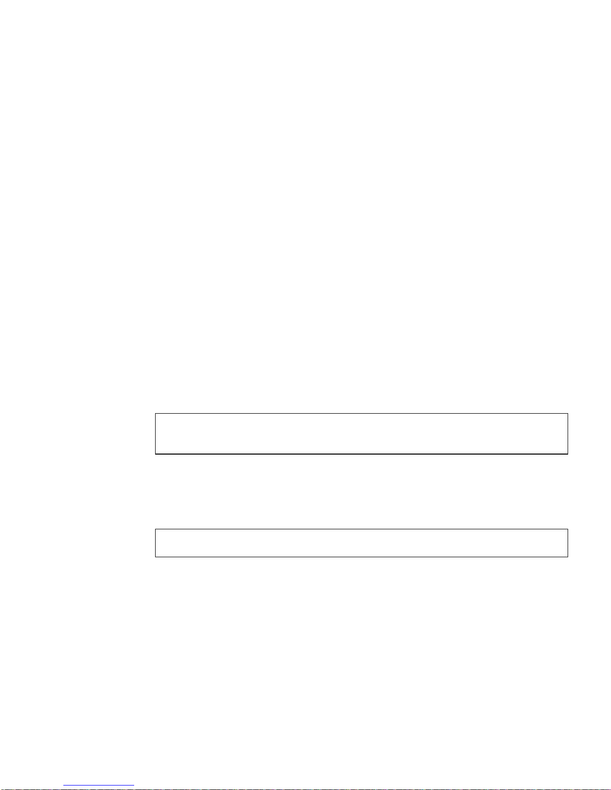
To set parameters so they remain in effect after you reboot the system, create a
/platform/sun4u/kernel/drv/ce.conf file and add parameter values to this
file when you need to set a particular parameter for a device in the system.
Setting Parameters Using the ndd Utility
Use the ndd utility to configure parameters that are valid until you reboot the
system. The ndd utility supports any networking driver that implements the Data
Link Provider Interface (DLPI).
The following sections describe how you can use the ce driver and the ndd utility to
modify (with the -set option) or display (without the -set option) the parameters
for each ce device.
▼ To Specify Device Instances for the ndd Utility
Before you use the ndd utility to get or set a parameter for a ce device, you must
specify the device instance for the utility.
1. Check the /etc/path_to_inst file to identify the instance associated with a
particular device.
# grep ce /etc/path_to_inst
"/pci@8,600000/network@1" 0 "ce"
In this example, the Gigabit Ethernet instance is from the installed adapter. The
instance number is in bold italics for clarity.
2. Use the instance number to select the device.
# ndd -set /dev/ce-instance-number
The device remains selected until you change the selection.
Noninteractive and Interactive Modes
You can use the ndd utility in two modes:
■ Noninteractive
■ Interactive
Chapter 4 Configuring Driver Parameters 47
Page 70
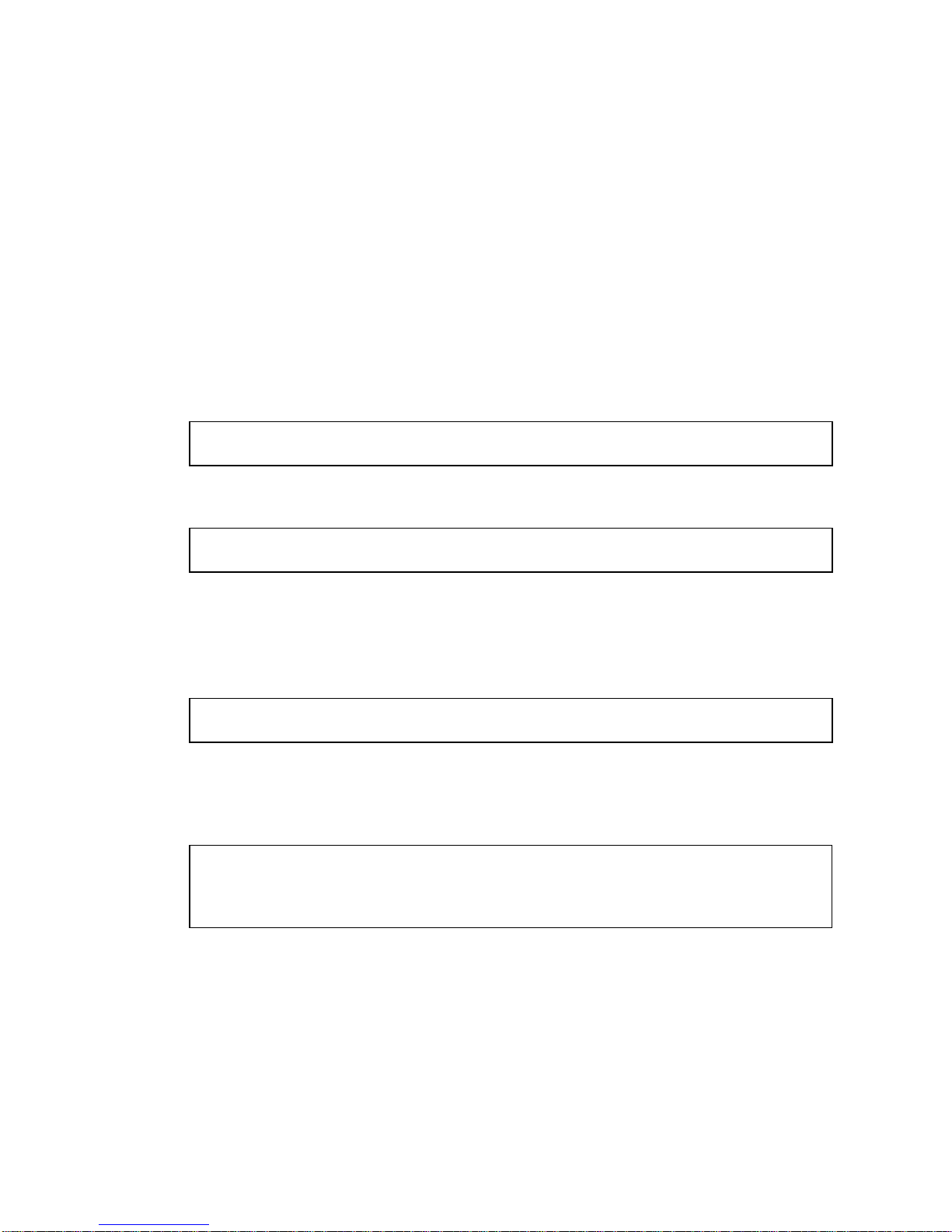
In noninteractive mode, you invoke the utility to execute a specific command. Once
the command is executed, you exit the utility. In interactive mode, you can use the
utility to get or set more than one parameter value. Refer to the ndd(1M) man page
for more information.
▼ To Use the ndd Utility in Noninteractive Mode
This section describes how to modify and display parameter values.
● To modify a parameter value, use the -set option.
If you invoke the ndd utility with the -set option, the utility passes value, which
must be specified, down to the named /dev/ce driver instance, and assigns the
value to the parameter:
# ndd -set /dev/ce parameter value
When you change any parameter, a message similar to the following appears:
ce0: xcvr addr:0x01 - link up 1000 Mbps full duplex
● To display the value of a parameter, specify the parameter name and omit the
value.
When you omit the -set option, the utility queries the named driver instance,
retrieves the value associated with the specified parameter, and prints it:
# ndd /dev/ce parameter
▼ To Use the ndd Utility in Interactive Mode
● To modify a parameter value in interactive mode, specify ndd /dev/ce:
# ndd /dev/ce
name to get/set? (Enter the parameter name or ? to view all
parameters)
After you enter the parameter name, the ndd utility prompts you for the parameter
value (see
TABLE 4-1 through TABLE 4-12).
48 Sun GigaSwift Ethernet Adapter Installation and User’s Guide • August 2004
Page 71

● To list all the parameters supported by the ce driver, type ?.
TABLE 4-1 through TABLE 4-12 for parameter descriptions.
See
# ndd /dev/ce
name to get/set ? ?
? (read only)
instance (read and write)
adv_autoneg_cap (read and write)
adv_1000fdx_cap (read and write)
adv_1000hdx_cap (read and write)
adv_100T4_cap (read and write)
adv_100fdx_cap (read and write)
adv_100hdx_cap (read and write)
adv_10fdx_cap (read and write)
adv_10hdx_cap (read and write)
adv_asmpause_cap (read and write)
adv_pause_cap (read and write)
master_cfg_enable (read and write)
master_cfg_value (read and write)
use_int_xcvr (read and write)
enable_ipg0 (read and write)
ipg0 (read and write)
ipg1 (read and write)
ipg2 (read and write)
rx_intr_pkts (read and write)
rx_intr_time (read and write)
red_dv4to6k (read and write)
red_dv6to8k (read and write)
red_dv8to10k (read and write)
red_dv10to12k (read and write)
tx_dma_weight (read and write)
rx_dma_weight (read and write)
infinite_burst (read and write)
disable_64bit (read and write)
accept_jumbo (read and write)
name to get/set ?
#
Setting the Autonegotiation Mode
By default, autonegotiation is set to on. This means that the adapter communicates
with its link partner to determine a compatible network speed, duplex mode, and
flow control capability.
Chapter 4 Configuring Driver Parameters 49
Page 72

▼ To Disable Autonegotiation Mode
If your network equipment does not support autonegotiation, or if you want to
specify your network speed, you can set autonegotiation to off on the ce device.
Note – Disabling autonegotiation mode can cause collisions.
1. Set the following driver parameters to the values that are described in the
documentation that shipped with your link partner (for example, a switch):
■ adv-1000fdx-cap
■ adv-100fdx-cap
■ adv-100hdx-cap
■ adv-10fdx-cap
■ adv-10hdx-cap
■ adv-asmpause-cap
■ adv-pause-cap
TABLE 4-2 for the descriptions and possible values of these parameters.
See
Note – According to IEEE 802.3 specifications, when using 1000 Mbps speed over
copper media, autonegotiation is not optional. In the absence of autonegotiation, (for
example, while using Forced mode), link syncing between link partners may not
happen and the link may not come up.
2. Set the adv-autoneg-cap parameter to 0.
# ndd -set /dev/ce adv-autoneg-cap 0
When you change any ndd link parameter, a message similar to the following
appears:
xcvr addr:0x00 - link up 100 Mbps full duplex
Setting Parameters Using the ce.conf File
Specify the driver parameter properties for each device by creating a ce.conf file in
the /platform/sun4u/kernel/drv directory. Use a ce.conf file when you need
to set a particular parameter for a device in the system. The parameters you can set
are the read and write parameters listed in “GigaSwift Ethernet Driver Parameter
Values and Definitions” on page 38.
50 Sun GigaSwift Ethernet Adapter Installation and User’s Guide • August 2004
Page 73

Note – Configuring the parameters by putting ndd commands in rcX.d scripts is
not supported.
The man pages for prtconf(1M) and driver.conf(4) include additional details.
The next procedure shows an example of setting parameters in a ce.conf file.
● To access any man page, type the man command plus the name of the man page.
For example, to access man pages for prtconf(1M), type:
% man prtconf
▼ To Set Driver Parameters Using a ce.conf File
1. Obtain the hardware path names for the ce devices in the device tree.
a. Check the /etc/driver_aliases file to identify the name associated with a
particular device:
# grep ce /etc/driver_aliases
ce "pci108e,abba"
ce "pci100b,35"
Note – ce "pci100b, 35" is used by the Sun GigaSwift Ethernet MMF/UTP
adapter.
b. Locate the path names and the associated instance numbers in the
/etc/path_to_inst file.
# grep ce /etc/path_to_inst
"/pci@8,600000/network@1" 0 "ce"
■ In this example:
■ The first part within the double quotes specifies the hardware node name in
the device tree.
■ The number not enclosed in quotes is the instance number (shown in bold
italics).
■ The last part in double quotes is the driver name.
■ In the hardware node name, the last component after the last / character and
before the @ character is the device name.
Chapter 4 Configuring Driver Parameters 51
Page 74

■ The path name before the last component is the parent name.
■ The number after the final @ character within quotes is the unit-address.
To identify a PCI device unambiguously in the ce.conf file, use the name, parent
name, and the unit-address for the device. Refer to the pci(4) man page for more
information about the PCI device specification.
In this example:
■ parent = "/pci@8,600000"
■ unit-address = "1"
2. Set the parameters for the above devices in the
/platform/sun4u/kernel/drv/ce.conf file.
In the following example, the adv_autoneg_cap and adv_1000fdx_cap
parameters are set for all Sun GigaSwift Ethernet devices. See the driver.conf(4)
man page for more information.
adv-autoneg-cap=0 adv-1000fdx-cap=0;
In the following example, the adv-autoneg-cap and adv-1000fdx-cap
parameters are set for a single instance of the Sun GigaSwift Ethernet device.
name="pci100b,35" parent="/pci@8,600000" unit-address="1"
adv-autoneg-cap=0 adv-100hdx-cap=0 adv-100fdx-cap=1 adv-1000fdx-cap=0 adv10hdx-cap=0 adv-10fdx-cap=0 adv-1000hdx-cap=0 adv-100T4-cap=0;
Note – If you omit the name=, parent=, and unit-address= definitions, the
settings become global to all Sun GigaSwift Ethernet instances.
3. Save the ce.conf file.
Usability Enhancements to the Driver
In older Ethernet device drivers, determining the link status for a driver required a
two-step process:
First, you had to set the instance:
# ndd -set /dev/ce instance 2
52 Sun GigaSwift Ethernet Adapter Installation and User’s Guide • August 2004
Page 75

Then you had to get the link status:
# ndd -get /dev/ce link_status
1
Starting in the Solaris 9 Operating System, this method of determining the link
status is discouraged, and in some cases, it is removed completely as a driver
feature.
The new improved approach moves all read-only parameters from the ndd options
into kstat. This simplifies getting link status information by allowing you to do it
with one simple command.
● To get the link status of a driver, type the following command:
# kstat ce:# | grep link_up
link_up 0
Where # = instance.
For more information about the kstat command, refer to the kstat man page.
Chapter 4 Configuring Driver Parameters 53
Page 76

GigaSwift Ethernet Driver Operating
Statistics
These statistics are part of the statistics presented by the netstat -k command.
TABLE 4-11 describes the read-only Media Independent Interface (MII) capabilities.
These parameters define the capabilities of the hardware. The Gigabit Media
Independent Interface (GMII) supports all of the following capabilities.
TABLE 4-11 Read-Only ce Device Capabilities
Parameter Description (Local interface Capabilities)
cap_autoneg 0 = Not capable of autonegotiation
1 = Autonegotiation capable
cap_1000fdx Local interface full-duplex capability
0 = Not 1000 Mbit/sec full-duplex capable
1 = 1000 Mbit/sec full-duplex capable
cap_1000hdx Local interface half-duplex capability
0 = Not 1000 Mbit/sec half-duplex capable
1 = 1000 Mbit/sec half-duplex capable
cap_100fdx Local interface full-duplex capability
0 = Not 100 Mbit/sec full-duplex capable
1 = 100 Mbit/sec full-duplex capable
cap_100hdx Local interface half-duplex capability
0 = Not 100 Mbit/sec half-duplex capable
1 = 100 Mbit/sec half-duplex capable
cap_10fdx Local interface full-duplex capability
0 = Not 10 Mbit/sec full-duplex capable
1 = 10 Mbit/sec full-duplex capable
54 Sun GigaSwift Ethernet Adapter Installation and User’s Guide • August 2004
Page 77

TABLE 4-11 Read-Only ce Device Capabilities (Continued)
Parameter Description (Local interface Capabilities)
cap_10hdx Local interface half-duplex capability
0 = Not 10 Mbit/sec half-duplex capable
1 = 10 Mbit/sec half-duplex capable
cap_asm_pause Local interface flow control capability
0 = Not asymmetric pause capable
1 = Asymmetric pause (from the local device) capable
cap_pause Local interface flow control capability
0 = Not Symmetric pause capable
1 = Symmetric pause capable
Reporting the Link Partner Capabilities
TABLE 4-12 describes the read-only link partner capabilities.
TABLE 4-12 Read-Only Link Partner Capabilities
Parameter Description
lp_cap_autoneg 0 = No autonegotiation
1 = Autonegotiation
lp_cap_1000fdx 0 = No 1000 Mbit/sec full-duplex transmission
1 = 1000 Mbit/sec full-duplex
lp_cap_1000hdx 0 = No 1000 Mbit/sec half-duplex transmission
1 = 1000 Mbit/sec half-duplex
lp_cap_100fdx 0 = No 100 Mbit/sec full-duplex transmission
1 = 100 Mbit/sec full-duplex
lp_cap_100hdx 0 = No 100 Mbit/sec half-duplex transmission
1 = 1000 Mbit/sec half-duplex
lp_cap_10fdx 0 = No 10 Mbit/sec full-duplex transmission
1 = 10 Mbit/sec full-duplex
lp_cap_10hdx 0 = No 10 Mbit/sec half-duplex transmission
1 = 10 Mbit/sec half-duplex
lp_cap_asm_pause 0 = Not asymmetric pause capable
1 = Asymmetric pause towards link partner capability
lp_cap_pause 0 = Not symmetric pause capable
1 = Symmetric pause capable
Chapter 4 Configuring Driver Parameters 55
Page 78

If the link partner is not capable of autonegotiation (when lp_autoneg_cap is 0),
the remaining information described in
TABLE 4-12 is not relevant and the parameter
value = 0.
If the link partner is capable of autonegotiation (when lp_autoneg_cap is 1), then
the speed and mode information is displayed when you use autonegotiation and the
link partner capabilities.
TABLE 4-13 describes the netstat -k transmit and receive parameters:
TABLE 4-13 Transmit and Receive Parameters
Parameter Description
xcvr_inits Number of physical layer re-initializations every time you change
link parameters using NDD this increments.
rev_id Revision ID of the GigaSwift Ethernet device useful for recognition
of device being used in the field.
xcvr_addr GMII/MII physical layer device address for management interface.
xcvr_id GMII/MII physical layer device Identification Decimal copy of MII
registers 2 and 3.
lb_mode Copy of the Loopback mode the device is in, if any.
qos_mode When zero, the TX queues operate in a simple round robin
queueing scheme, based on TCP/UDP destination port number. If
set the TX queues operate in a scheme designed to provide VLAN
priorities.
tx_starts Number of times that the driver attempted to transmit a packet.
tx_dma_bind_fail Number of times a page table entry was not available to enable the
driver to map the kernel memory to device accessible memory for
transmission.
tx_queue0 Number of packets queued for transmission on the first hardware
transmit queue.
tx_queue1 Number of packets queued for transmission on the second
hardware transmit queue.
tx_queue2 Number of packets queued for transmission on the third hardware
transmit queue.
tx_queue3 Number of packets queued for transmission on the fourth hardware
transmit queue.
tx_max_pend Maximum number of transmits pending on any of the four queues.
rx_hdr_pkts Number of packets received that were less than 256 bytes.
rx_mtu_pkts Number of packets received that were greater than 256 bytes and
less than 1514 bytes.
56 Sun GigaSwift Ethernet Adapter Installation and User’s Guide • August 2004
Page 79

TABLE 4-13 Transmit and Receive Parameters (Continued)
Parameter Description
rx_split_pkts Number of packets that were split across two pages.
rx_no_comp_wb Number of times the hardware cannot post completion entries for
received data.
rx_no_buf Number of times the hardware cannot receive data because there is
no more receive buffer space.
rx_new_pages Number of pages that got replaced during reception.
rx_new_hdr_pgs Number of pages that were filled with packets less than 256 bytes
that got replaced during reception.
rx_new_mtu_pgs Number of pages that were filled with packets greater than 256
bytes and less than 1514 that got replaced during reception.
rx_new_nxt_pgs Number of pages that contained packets that were split across
pages that got replaced during reception.
rx_hdr_drops Number of times an entire page of packets less than 256 bytes each
was dropped because the driver was unable to map a new page to
replace it.
rx_mtu_drops Number of times an entire page of packets greater than 256 bytes
and less than 1514 each was dropped because the driver was unable
to map a new page to replace it.
rx_nxt_drops Number of times a page with a split packet was dropped because
the driver was unable to map a new one to replace it.
rx_rel_flow Number of times the driver was told to release a flow.
Chapter 4 Configuring Driver Parameters 57
Page 80

▼ To Check Link Partner Settings
● If you are running the Solaris 8 Operating System, type the netstat -k
command as superuser:
# netstat -k ce0
ce0:
ipackets 0 ipackets64 0 ierrors 0 opackets 0 opackets64 0
oerrors 0 collisions 0 rbytes 0 rbytes64 0 obytes 0 obytes64 0
multircv 0 multixmt 0 brdcstrcv 0 brdcstxmt 0 norcvbuf 0
noxmtbuf 0 first_collision 0 excessive_collisions 0 late_collisions 0
peak_attempts 0 length_err 0 alignment_err 0 crc_err 0 code_violations 0
ifspeed 1000000000 promisc off rev_id 48 xcvr_inits 1 xcvr_inuse 1
xcvr_addr 1 xcvr_id 536894584 cap_autoneg 1 cap_1000fdx 1 cap_1000hdx 1
cap_100T4 0 cap_100fdx 1 cap_100hdx 1 cap_10fdx 1 cap_10hdx 1
cap_asmpause 0 cap_pause 0 lp_cap_autoneg 1 lp_cap_1000fdx 1
lp_cap_1000hdx 1 lp_cap_100T4 0 lp_cap_100fdx 1 lp_cap_100hdx 1
lp_cap_10fdx 1 lp_cap_10hdx 1 lp_cap_asmpause 0 lp_cap_pause 1
link_T4 0 link_speed 1000 link_duplex 2 link_asmpause 0 link_pause 0
link_up 1 mac_mtu 0 lb_mode 0 qos_mode 0 trunk_mode 0 tx_inits 0
tx_starts 0 tx_nocanput 0 tx_msgdup_fail 0 tx_allocb_fail 0
tx_no_desc 0 tx_dma_bind_fail 0 tx_uflo 0 tx_queue0 0 tx_queue1 0
tx_queue2 0 tx_queue3 0 tx_hdr_pkts 0 tx_ddi_pkts 0 tx_dvma_pkts 0
mdt_reqs 0 mdt_hdr_bufs 0 mdt_pld_bufs 0 mdt_pkts 0 mdt_hdrs 0
mdt_plds 0 mdt_hdr_bind_fail 0 mdt_pld_bind_fail 0 tx_jumbo_pkts 0
tx_max_pend 0 rx_inits 0 rx_jumbo_pkts 0 rx_hdr_pkts 0 rx_mtu_pkts 0
rx_split_pkts 0 rx_no_buf 0 rx_no_comp_wb 0 rx_ov_flow 0
rx_len_mm 0 rx_tag_err 0 rx_nocanput 0 rx_msgdup_fail 0
rx_allocb_fail 0 rx_new_pages 0 rx_new_hdr_pgs 0 rx_new_mtu_pgs 0
rx_new_nxt_pgs 0 rx_hdr_drops 0 rx_mtu_drops 0 rx_nxt_drops 0
rx_rel_flow 0 rx_rel_bit 0 rx_pkts_dropped 0 pci_bus_speed 66
pci_err 0 pci_rta_err 0 pci_rma_err 0 pci_parity_err 0 pci_bad_ack_err 0
pci_drto_err 0 pci_dmawz_err 0 pci_dmarz_err 0 rx_taskq_waits 0
ipackets_cpu00 0 ipackets_cpu01 0 ipackets_cpu02 0 ipackets_cpu03 0
● If you are running the Solaris 9 Operating System, type the kstat command as
superuser:
CODE EXAMPLE 4-1 Output from the kstat Command
# kstat ce:0
module: ce instance: 0
name: ce0 class: net
alignment_err 0
brdcstrcv 0
brdcstxmt 0
cap_1000fdx 1
58 Sun GigaSwift Ethernet Adapter Installation and User’s Guide • August 2004
Page 81

CODE EXAMPLE 4-1 Output from the kstat Command (Continued)
# kstat ce:0
cap_1000hdx 1
cap_100T4 0
cap_100fdx 1
cap_100hdx 1
cap_10fdx 1
cap_10hdx 1
cap_asmpause 0
cap_autoneg 1
cap_pause 0
code_violations 0
collisions 0
crc_err 0
crtime 2345.407585961
excessive_collisions 0
first_collision 0
ierrors 0
ifspeed 0
ipackets 0
ipackets64 0
ipackets_cpu00 0
ipackets_cpu01 0
ipackets_cpu02 0
ipackets_cpu03 0
late_collisions 0
lb_mode 0
length_err 0
link_T4 0
link_asmpause 0
link_duplex 0
link_pause 0
link_speed 0
link_up 0
lp_cap_1000fdx 0
lp_cap_1000hdx 0
lp_cap_100T4 0
lp_cap_100fdx 0
lp_cap_100hdx 0
lp_cap_10fdx 0
lp_cap_10hdx 0
lp_cap_asmpause 0
lp_cap_autoneg 0
lp_cap_pause 0
multircv 0
multixmt 0
norcvbuf 0
noxmtbuf 0
Chapter 4 Configuring Driver Parameters 59
Page 82

CODE EXAMPLE 4-1 Output from the kstat Command (Continued)
# kstat ce:0
obytes 0
obytes64 0
oerrors 0
opackets 0
opackets64 0
pci_bad_ack_err 0
pci_dmarz_err 0
pci_dmawz_err 0
pci_drto_err 0
pci_err 0
pci_parity_err 0
pci_rma_err 0
pci_rta_err 0
peak_attempts 0
promisc off
qos_mode 0
rbytes 0
rbytes64 0
rev_id 1
rx_allocb_fail 0
rx_hdr_drops 0
rx_hdr_pkts 0
rx_inits 0
rx_len_mm 0
rx_msgdup_fail 0
rx_mtu_drops 0
rx_mtu_pkts 0
rx_new_hdr_pgs 0
rx_new_mtu_pgs 0
rx_new_nxt_pgs 0
rx_new_pages 0
rx_no_buf 0
rx_no_comp_wb 0
rx_nocanput 0
rx_nxt_drops 0
rx_ov_flow 0
rx_pkts_dropped 0
rx_rel_bit 0
rx_rel_flow 0
rx_split_pkts 0
rx_tag_err 0
rx_taskq_waits 0
snaptime 2352.506837979
tx_allocb_fail 0
tx_ddi_pkts 0
tx_dma_bind_fail 0
60 Sun GigaSwift Ethernet Adapter Installation and User’s Guide • August 2004
Page 83

CODE EXAMPLE 4-1 Output from the kstat Command (Continued)
# kstat ce:0
tx_dma_hdr_bind_fail 0
tx_dma_pld_bind_fail 0
tx_dvma_pkts 0
tx_hdr_pkts 0
tx_inits 0
tx_max_desc 0
tx_max_pend 0
tx_msgdup_fail 0
tx_no_desc 0
tx_nocanput 0
tx_queue0 3
tx_queue1 0
tx_queue2 0
tx_queue3 0
tx_starts 0
tx_uflo 0
xcvr_addr 1
xcvr_id 2121809
xcvr_inits 1
xcvr_inuse 1
▼ To Discover Link Partner Capabilities
● Use the kstat command to discover link partner capabilities.
# kstat ce:0 | grep lp_
lp_cap_1000fdx 1
lp_cap_1000hdx 1
lp_cap_100T4 0
lp_cap_100fdx 0
lp_cap_100hdx 0
lp_cap_10fdx 0
lp_cap_10hdx 0
lp_cap_asmpause 0
lp_cap_autoneg 1
lp_cap_pause 0
Chapter 4 Configuring Driver Parameters 61
Page 84

▼ To Discover Link Settings
● Use the kstat command to discover link settings.
# kstat ce:0 | grep link
link_T4 0
link_asmpause 0
link_duplex 2
link_pause 0
link_speed 1000
link_up 1
Configuration Checking
The jumbo frame configuration checking occurs at Layer 2 or Layer 3, depending on
the configuration method.
Layer 2 Configuration Checking
You can view the MTU configuration of a ce instance at any time using the kstat
command. The kstat mac_mtu variable represents the complete size of the
Ethernet frame, which includes the Ethernet header, maximum payload, and crc.
This value is consistent with the definition of MTU presented by switch vendors.
Use the following command to get the information:.
# kstat ce:0 | grep mac_mtu
Layer 3 Configuration Checking
You can check the Layer 3 configuration by invoking the ifconfig command on a
preconfigured interface as shown in the above examples:.
ifconfig ce123000
ce123000: flags=1000843<.....> mtu 9194
inet ip-address-vlan-1 .......
ether 8:0:20:c4:51:df
62 Sun GigaSwift Ethernet Adapter Installation and User’s Guide • August 2004
Page 85

CHAPTER
5
Configuring VLANs
This chapter explains VLANs in detail and provides configuration instructions and
examples.
VLANs: Virtual Local Area Networks (VLANs) are commonly used to split up
groups of network users into manageable broadcast domains, to create logical
segmentation of workgroups, and to enforce security policies among each logical
segment. With multiple VLANs on an adapter, a server with a single adapter can
have a logical presence on multiple IP subnets. By default, 128 VLANs can be
defined for each VLAN-aware adapter on your server. However, this number can be
increased by changing the system parameters.
If your network does not require multiple VLANs, you can use the default
configuration, in which case no further configuration is necessary.
■ “Overview of VLANs” on page 63
■ “Configuring VLANs” on page 66
Note – If you change any of the VLAN configuration parameters, you must reboot
the system before the changes take effect. If you make changes and do not reboot,
you may experience configuration problems.
Overview of VLANs
VLANs enable you to split your physical LAN into logical subparts, providing an
essential tool for increasing the efficiency and flexibility of your network.
63
Page 86
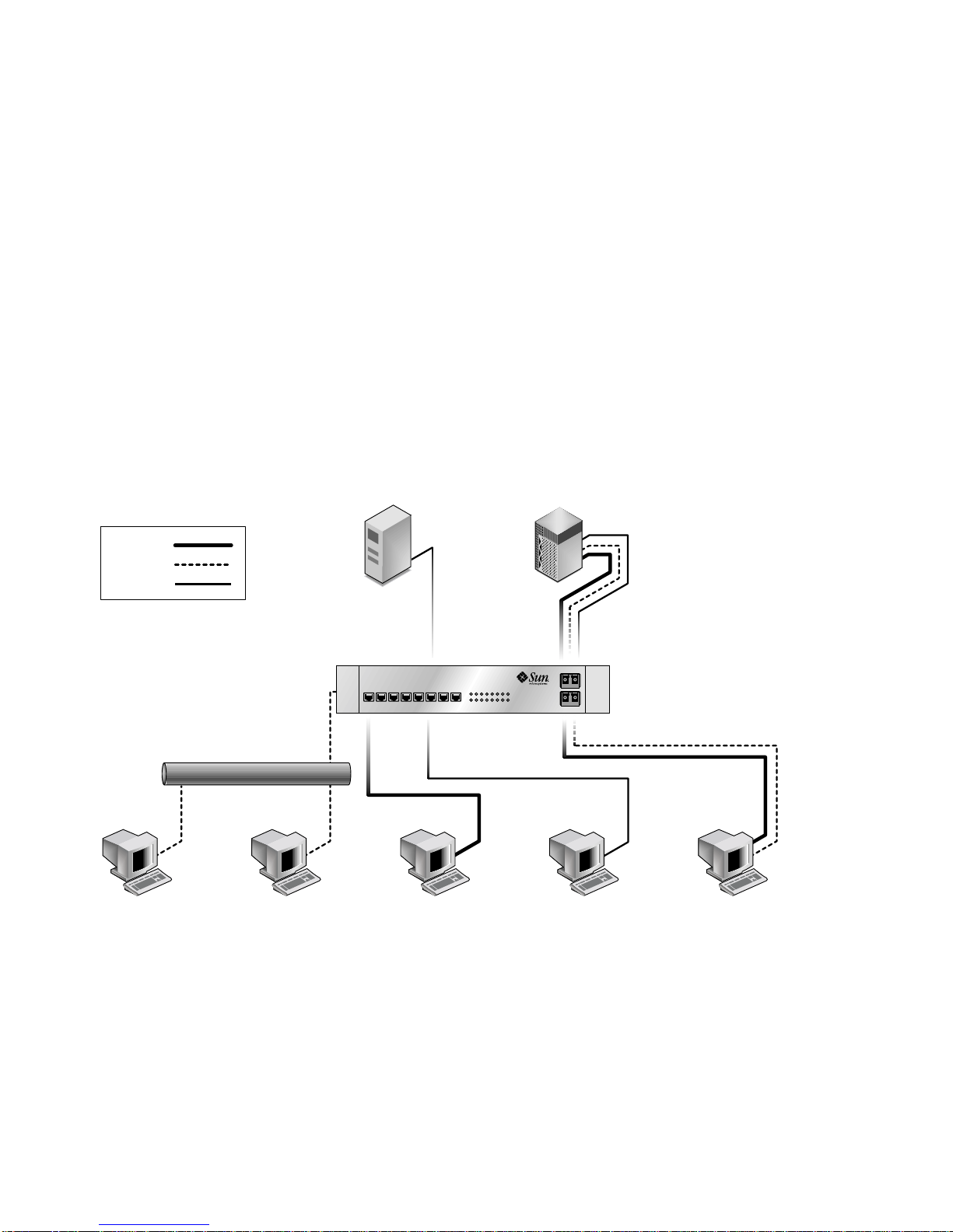
VLAN 1
VLAN 2
VLAN 3
VLANs are commonly used to separate groups of network users into manageable
broadcast domains, to create logical segmentation of workgroups, and to enforce
security policies among each logical segment. Each defined VLAN behaves as its
own separate network, with its traffic and broadcasts isolated from the others,
increasing the bandwidth efficiency within each logical group.
Although VLANs are commonly used to create individual broadcast domains
and/or separate IP subnets, it can be useful for a server to have a presence on more
than one VLAN simultaneously. Several Sun products support multiple VLANs on a
per port or per interface basis, allowing very flexible network configurations.
FIGURE 5-1 shows an example network that uses VLANs.
Main Server
Accounting
Server
(VLAN 3)
Adapter
GIgabit/Tagged
(All VLANs)
Shared
Media
Segment
Software
PC 1
(VLAN 2)
FIGURE 5-1 Example of Servers Supporting Multiple VLANs with Tagging Adapters
Software
PC 2
(VLAN 2)
Engineering
PC 3
(VLAN 1)
Accounting
PC 4
(VLAN 3)
The example network has the following features:
64 Sun GigaSwift Ethernet Adapter Installation and User’s Guide • August 2004
Engineering/
Software PC 5
Adapter
Gigabit/Tagged
(VLAN 1 & 2)
Page 87

The physical LAN network consists of a switch, two servers, and five clients. The
LAN is logically organized into three different VLANs, each representing a different
IP subnet.
■ VLAN 1 is an IP subnet consisting of the Main Server, Client 3, and Client 5. This
represents an engineering group.
■ VLAN 2 includes the Main Server, Clients 1 and 2 by means of a shared media
segment, and Client 5. This is a software development group.
■ VLAN 3 includes the Main Server, the Accounting Server and Client 4. This is an
accounting group.
The Main Server is a high-use server that needs to be accessed from all VLANs and
IP subnets. The server has a Sun GigaSwift Ethernet adapter installed. All three IP
subnets are accessed by means of the single physical adapter interface. The server is
attached to one of the SunSwitch’s Gigabit Ethernet ports, which is configured for
VLANs 1, 2, and 3. Both the adapter and the connected SunSwitch™ port have
tagging turned on. Because of the tagging VLAN capabilities of both devices, the
sever is able to communicate on all three IP subnets in this network, but continues to
maintain broadcast separation between all of them.
The Accounting Server is available to VLAN 3 only. It is isolated from all traffic on
VLANs 1 and 2. The switch port connected to the server has tagging turned off.
Clients 1 and 2 are attached to a shared media hub that is then connected to the
switch. They belong to VLAN 2 only, and are logically in the same IP subnet as the
Main Server and Client 5. The switch port connected to this segment has tagging
turned off.
Client 3 is a member of VLAN 1, and can communicate only with the Main Server
and Client 5. Tagging is not enabled on Client 3’s switch port.
Client 4 is a member of VLAN 3, and can communicate only with the servers.
Tagging is not enabled on Client 4’s switch port.
Client 5 is a member of both VLANs 1 and 2, and has a Sun GigaSwift Ethernet
adapter installed. It is connected to switch port 10. Both the adapter and the switch
port are configured for VLANs 1 and 2 and have tagging enabled.
VLAN tagging is only required to be enabled on switch ports that create trunk links
to other VLAN-aware Ethernet switches, or on ports connected to tag-capable endstations, such as servers or workstations with VLAN-aware adapters.
Chapter 5 Configuring VLANs 65
Page 88

Configuring VLANs
VLANs can be created according to various criteria, but each VLAN must be
assigned a VLAN tag or VLAN ID (VID). The VID is a 12-bit identifier between 1
and 4094 that identifies a unique VLAN. For each network interface (ce0, ce1, ce2
and so on), 4094 possible VLAN IDs can be selected. Because IP subnets are
commonly used, it is best to use IP subnets when setting up a VLAN network
interface. This means that each VID assigned to a VLAN interface of a physical
network interface will belong to different subnets.
Tagging an Ethernet frame requires the addition of a tag header to the frame. The
header is inserted immediately following the Destination MAC address and the
Source MAC address. The tag header consists of two bytes of Ethernet Tag Protocol
Identifier (TPID, 0x8100) and two bytes of Tag Control Information (TCI).
shows the Ethernet Tag Header format.
Octet
1
2
3
4
3 bits
TPID (0x8100
1
12 bytes
bit
FIGURE 5-2
User_priority
FIGURE 5-2 Ethernet Tag Header Format
CFI
VID
By default, a single VLAN is configured for every port, which groups all ports into
the same broadcast domain, just as if there were no VLANs at all, VLAN tagging for
the switch port turned off.
Note – If you configure a VLAN virtual device for an adapter, all traffic sent or
received by that adapter must be in VLAN-tagged format.
66 Sun GigaSwift Ethernet Adapter Installation and User’s Guide • August 2004
Page 89

▼ To Configure Static VLANs
1. Create one hostname6.cenumber file for each VLAN that will be configured for
each adapter on the server.
Use the following naming format that includes both the VID and the physical point
of attachment (PPA):
VLAN logical PPA = 1000 * VID + Device PPA
ce123000 = 1000*123 + ce
This format limits the maximum number of PPAs (instances) you can configure to
1000 in the /etc/path_to_inst file.
For example, on a server with the Sun GigaSwift Ethernet adapter having an
instance of 0, that belongs to a member of two VLANs, with VID 123 and 224, you
would use ce123000 and ce224000, respectively, as the two VLAN PPAs.
2. Use the ifconfig(1M) to configure a VLAN virtual device, for example:
# ifconfig ce123000 plumb up
# ifconfig ce224000 plumb up
The output of ifconfig -a on a system having VLAN devices ce123000 and
ce224000:
# ifconfig -a
lo0: flags=1000849<UP,LOOPBACK,RUNNING,MULTICAST,IPv4> mtu 8232 index 1
inet 127.0.0.1 netmask ff000000
hme0: flags=1000843<UP,BROADCAST,RUNNING,MULTICAST,IPv4> mtu 1500 index 2
inet 129.144.131.91 netmask ffffff00 broadcast 129.144.131.255
ether 8:0:20:a4:4f:b8
ce123000: flags=1000843<UP,BROADCAST,RUNNING,MULTICAST,IPv4> mtu 1500 index 3
inet 199.199.123.3 netmask ffffff00 broadcast 199.199.123.255
ether 8:0:20:a4:4f:b8
ce224000: flags=1000843<UP,BROADCAST,RUNNING,MULTICAST,IPv4> mtu 1500 index 4
inet 199.199.224.3 netmask ffffff00 broadcast 199.199.224.225
ether 8:0:20:a4:4f:b8
3. On the switch, set VLAN tagging and set VLAN ports to coincide with the VLANs
you’ve set up on the server.
Use the examples in Step 2, you would set up VLAN ports 123 and 224 on the
switch.
Refer to the documentation that came with your switch for specific instructions for
setting VLAN tagging and ports.
Chapter 5 Configuring VLANs 67
Page 90

68 Sun GigaSwift Ethernet Adapter Installation and User’s Guide • August 2004
Page 91

APPENDIX
A
Installing the Software Manually
This appendix describes how to install the driver software manually. It contains the
following sections:
■ “Installing the Driver Software Manually” on page 69
■ “Verifying Patches” on page 74
Installing the Driver Software Manually
The Sun GigaSwift Ethernet Adapter CD contains the driver software required to
operate the adapter. When you update your Solaris operating system, refer to the
documentation that shipped with the Solaris Supplement CD-ROM for a listing of the
available network drivers. Install the Sun GigaSwift Ethernet driver for your
updated version of the Solaris operating system.
▼ To Install the Driver Software Manually
1. Become superuser.
2. Insert the Sun GigaSwift Ethernet Adapter CD into a CD-ROM drive that is
connected to your system.
■ If your system is running Sun Enterprise Volume Manager™, it should
automatically mount the CD-ROM to the /cdrom/cdrom0 directory.
69
Page 92

■ If your system is not running Volume Manager, mount the CD-ROM as follows:
# mkdir /cdrom
# mkdir /cdrom/cdrom0
# mount -F hsfs -o ro /dev/dsk/c0t6d0s2 /cdrom/cdrom0
You will see the following files and directories in the
/cdrom/sun_gigaswift_ethernet_driver directory or the
/cdrom/cdrom0 directory, depending on how you mounted the CD-ROM.
TABLE A-1 Files and Directories on the CD-ROM
File or Directory Contents
Copyright U.S. copyright file
FR_Copyright French copyright file
For Solaris 7 and 8 operating
systems
GigabitEthernet/Solaris_OS
-VER/Packages/
For Solaris 9 SPARC architecture
GigabitEthernet/Solaris_9/
sparc/Packages/
Contains the Sun GigaSwift Ethernet software
packages applicable to your version (OS-VER) of the
Solaris software:
• SUNWcea—32-bit adb macros
• SUNWceax—64-bit adb macros
• SUNWced.u—32-bit adapter driver
• SUNWcedx.u—64-bit adapter driver
• SUNWcedu—adapter driver headers
• SUNWcem—man pages (optional, Solaris 8 only)
(For Solaris 8 software only) The optional VLAN
packages:
• SUNWvld—VLAN utility routines
• SUNWvldx—VLAN utility routines (64-bit)
• SUNWvldu—VLAN utility headers
Contains the Sun GigaSwift Ethernet software
packages applicable to to the Solaris 9 SPARC version
of the software:
• SUNWcea—32-bit adb macros
• SUNWceax—64-bit adb macros
• SUNWced.u—32-bit adapter driver
• SUNWcedx.u—64-bit adapter driver
• SUNWcedu—adapter driver headers
• SUNWcem—man pages
70 Sun GigaSwift Ethernet Adapter Installation and User’s Guide • August 2004
Page 93

TABLE A-1 Files and Directories on the CD-ROM (Continued)
File or Directory Contents
(For Solaris 9 software only) The optional VLAN
packages:
• SUNWvld—VLAN utility routines
• SUNWvldx—VLAN utility routines (64-bit)
• SUNWvldu—VLAN utility headers
For Solaris 9 x86 architecture
GigaSwiftEthernet/Solaris_9
/i386/Packages/
Contains the Sun GigaSwift Ethernet software
packages applicable to to the Solaris 9 x86 version of
the software:
• SUNWcea—32-bit adb macros
• SUNWced—adapter driver
• SUNWcedu—adapter driver headers
• SUNWcem—man pages
The optional VLAN packages:
• SUNWvld—VLAN utility routines
• SUNWvldu—VLAN utility headers
GigaSwiftEthernet/Docs/en Contains PDF copy of the user manual
Note – If you intend to use VLAN, you must install VLAN packages when you
install the software packages.
3. Determine if the ce and vlan drivers are installed on the system:
■ If you are using a Solaris SPARC system:
#/usr/bin/pkginfo SUNWced SUNWcedx SUNWvld SUNWvldx
system SUNWced Sun GigaSwift Ethernet Adapter (32-bit Driver)
system SUNWcedx Sun GigaSwift Ethernet Adapter (64-bit Driver)
system SUNWvld Sun Ethernet Vlan Utility Routines
system SUNWvldx Sun Ethernet Vlan Utility Routines (64-bit)
■ If you are using a Solaris x86 system:
#/usr/bin/pkginfo SUNWced SUNWvld
system SUNWced Sun GigaSwift Ethernet Adapter
system SUNWvld Sun GigaSwift Ethernet Adapter
■ If the output of the command is similar to the appropriate example in Step 3, skip
to Step 6.
Appendix A Installing the Software Manually 71
Page 94

■ If nothing is reported back on SUNWced or SUNWcedx, then proceed to Step 4 and
select SUNWcea, SUNWceax, SUNWced.u, SUNWcedx.u, SUNWcedu, and SUNWcem
(if present).
■ If nothing is reported back for SUNWvld or SUNWvldx, then proceed to Step 4 and
select SUNWvld, SUNWvldx, and SUNWvldu packages.
■ If nothing is reported back, then proceed to Step 4 and select "all" packages.
4. Install the software packages by typing the following at the command line,
replacing the OS_VER with your version of the Solaris operating system:
■ If your system is running Solaris 7 or 8 software type the following:
# /usr/sbin/pkgadd -d /cdrom/cdrom0/GigaSwiftEthernet/Solaris_OS_VER/Packages/
Where OS_VER is 7 or 8
For example, if your system is running the Solaris 8 operating system, you would
type the following:
# /usr/sbin/pkgadd -d /cdrom/cdrom0/GigaSwiftEthernet/Solaris_8/Packages/
■ If your system is running Solaris 9 SPARC software type the following:
# /usr/sbin/pkgadd -d /cdrom/cdrom0/GigaSwiftEthernet/Solaris_9/Sparc/Packages/
72 Sun GigaSwift Ethernet Adapter Installation and User’s Guide • August 2004
Page 95

■ If your system is running Solaris 9 x86 software type the following:
# pkgadd -d /Solaris_9/i386/Packages/
A menu similar to the following displays:
The following packages are available:
1 SUNWcea Sun GigaSwift Ethernet Adapter Driver 32 bit adb Macros
(sparc) 1.0,REV=2001.05.04
2 SUNWceax Sun GigaSwift Ethernet Adapter Driver 64 bit adb Macros
(sparc) 1.0,REV=2001.05.04
3 SUNWced.u Sun GigaSwift Ethernet Adapter (32-bit Driver)
(sparc.sun4u) 1.0,REV=2001.05.04
4 SUNWcedu Sun GigaSwift Ethernet Adapter Driver Headers
(sparc) 1.0,REV=2001.05.04
5 SUNWcedx.u Sun GigaSwift Ethernet Adapter (64-bit Driver)
(sparc.sun4u) 1.0,REV=2001.05.04
6 SUNWcem Sun GigaSwift Ethernet Adapter Driver Man Pages
(sparc) 1.0,REV=2001.05.04
7 SUNWvld Sun Ethernet Vlan Utility Routines
(sparc) 1.0,REV=2001.05.04
8 SUNWvldu Sun Ethernet Vlan Utility Headers
(sparc) 1.0,REV=2001.05.04
9 SUNWvldx Sun Ethernet Vlan Utility Routines (64-bit)
(sparc) 1.0,REV=2001.05.04
Select package(s) you wish to process (or ’all’ to process
all packages). (default: all) [?,??,q]:
5. Select the packages you want to install:
■ Press Return or type all to accept the default and install all packages (if neither
the GigaSwfit Ethernet Driver nor VLAN Utility packages are installed).
■ Type the numbers of all but the optional packages if you prefer not to install
them.
See
TABLE A-1 to identify the optional packages.
6. If the packages are already installed, verify the patch version.
See the following section.
Appendix A Installing the Software Manually 73
Page 96

Verifying Patches
Verify whether your system has the needed patches for your version of the Solaris
Operating System to ensure that you do not need to add patches.
Note – If patches meet the requirements, nothing needs to be installed on the install
system.
TABLE A-2 lists and describes the patch versions:
TABLE A-2 Patch Versions
Solaris Patch Version Description
7 112327-18 SunOS 2.7: Sun GigaSwift Ethernet 1.0 driver patch
8 111883-24 SunOS 5.8: Sun GigaSwift Ethernet 1.0 driver patch
112119-04 SunOS 5.8: vlan driver patch*
9 112817-17 SunOS 5.9: Sun GigaSwift Ethernet 1.0 driver patch
114600-02 SunOS 5.9: vlan driver patch*
9 x86 117714-01 SunOS 5.9_x86: Sun GigaSwift Ethernet 1.0 driver patch
* Only required if packages SUNWvld or SUNWvldx are installed.
Table describes the patch versions.
▼ To Install Patches
1. Determine the version of the Solaris Operating System your system is running:
% cat /etc/release
Solaris 9 8/03 s9s_u4wos_08a SPARC
Copyright 2003 Sun Microsystems, Inc. All Rights Reserved.
Use is subject to license terms.
Assembled 13 June 2003
2. Verify patch versions for the GigaSwift Etnernet driver:
74 Sun GigaSwift Ethernet Adapter Installation and User’s Guide • August 2004
Page 97

■ To verify patches for the Solaris 8 Operating System, type the following:
# showrev -p | grep 111883
The patch version should be -24 or greater.
■ To verify patches for the Solaris 9 SPARC Operating System, type the following:
# showrev -p | grep 112817
The patch version should be -17 or greater.
■ To verify patches for the Solaris 9 x86 Operating System, type the following:
# showrev -p | grep 117714
The patch version should be -01 or greater.
3. If the patch is not present or the patch version is not correct, install the correct
patch:
# cd /cdrom/cdrom0
# patchadd GigaSwiftEthernet/OS/Patches/patch-id
■ If your system is running Solaris 7 or 8 software type the following:
# patchadd GigaSwiftEthernet/OS/Patches/patch-id
Where:
OS_VER = Solaris 7 or Solaris 8
patch-id = 112327-18 for Solaris 7 or 11883-24 for Solaris 8
■ If your system is running Solaris 9 SPARC software type the following:
# cd /cdrom/cdrom0
# patchadd GigaSwiftEthernet/Solaris_9/sparc/Patches/112817-17
Appendix A Installing the Software Manually 75
Page 98

■ If your system is running Solaris 9 x86 software type the following:
# cd /cdrom/cdrom0
# patchadd GigaSwiftEthernet/Solaris_9/i386/Patches/117714-01
▼ To Install a Sun VLAN Utility Patch
Note – The VLAN Utility is only supported in Solaris 8 and Solaris 9 software.
1. Determine the version of the Solaris Operating System your system is running:
% cat /etc/release
Solaris 9 8/03 s9s_u4wos_08a SPARC
Copyright 2003 Sun Microsystems, Inc. All Rights Reserved.
Use is subject to license terms.
Assembled 13 June 2003
2. Verify patch versions for the VLAN utility software:
■ To verify patches for the Solaris 8 Operating System, type the following:
# showrev -p | grep 112119
The patch version should be -04 or greater.
■ To verify patches for the Solaris 9 Operating System, type the following:
# showrev -p | grep 114600
Verify that the patch version is -02 or higher.
3. If the patch versions are not correct, install the correct patch.
■ If your system is running the Solaris 8 SPARC Operating System, type the
following:
# cd /cdrom/cdrom0
# patchadd GigaSwiftEthernet/Solaris_8/Patches/
112119-04
76 Sun GigaSwift Ethernet Adapter Installation and User’s Guide • August 2004
Page 99

4. If your system is running the Solaris 9 SPARC Operating System, type the following:
# cd /cdrom/cdrom0
# patchadd GigaSwiftEthernet/Solaris_9/Sparc/Patches/
You will see output similar to the following Solaris 9 SPARC Operating System
example:
Verifying sufficient filesystem capacity (dry run method)...
Installing patch packages...
114600-02
Patch number
See /var/sadm/patch/
Patch packages installed:
SUNWvld
SUNWvldu
SUNWvldx
114600-02 has been successfully installed.
114600-02/log for details
Appendix A Installing the Software Manually 77
Page 100

78 Sun GigaSwift Ethernet Adapter Installation and User’s Guide • August 2004
 Loading...