


Sun Fire X4800 Server Installation Guide
Part No: 821–0285
—12, March 2011

Copyright © 2010, 2011, Oracle and/or its aliates. All rights reserved.
License Restrictions Warranty/Consequential Damages Disclaimer
This software and related documentation are provided under a license agreement containing restrictions on use and disclosure and are protected by intellectual
property laws. Except as expressly permitted in your license agreement or allowed by law, you may not use, copy, reproduce, translate, broadcast, modify, license,
transmit, distribute, exhibit, perform, publish or display any part, in any form, or by any means. Reverse engineering, disassembly, or decompilation of this software,
unless required by law for interoperability, is prohibited.
Warranty Disclaimer
The information contained herein is subject to change without notice and is not warranted to be error-free. Ifyou nd any errors, please report them to us in writing.
Restricted Rights Notice
If this is software or related documentation that is delivered to the U.S. Government or anyone licensing it on behalf of the U.S. Government, the following notice is
applicable:
U.S. GOVERNMENT RIGHTS
Programs, software, databases, and related documentation and technical data delivered to U.S. Government customers are "commercial computer software" or
"commercial technical data" pursuant to the applicable Federal Acquisition Regulation and agency-specic supplemental regulations. As such, the use, duplication,
disclosure, modication, and adaptation shall be subject to the restrictions and license terms set forth in the applicable Government contract, and, to the extent
applicable by the terms of the Government contract, the additional rights set forth in FAR 52.227-19, Commercial Computer Software License (December 2007).
Oracle America, Inc., 500 Oracle Parkway,Redwood City, CA 94065.
Hazardous Applications Notice
This software or hardware is developed for general use in a variety of information management applications. It is not developed or intended for use in any inherently
dangerous applications, including applications that may create a risk of personal injury. If you use this software or hardware in dangerous applications, then you shall
be responsible to take all appropriate fail-safe, backup, redundancy, and other measures to ensure its safe use. Oracle Corporation and its aliates disclaim any
liability for any damages caused by use of this software or hardware in dangerous applications.
Trademark Notice
Oracle and Java are registered trademarks of Oracle and/or its aliates. Other names may be trademarks of their respective owners.
Intel and Intel Xeon are trademarks or registered trademarks of Intel Corporation. All SPARC trademarks are used under license and are trademarks or registered
trademarks of SPARC International, Inc. AMD, Opteron, the AMD logo, and the AMD Opteron logo are trademarks or registered trademarks of Advanced Micro
Devices. UNIX is a registered trademark of The Open Group in the United States and other countries.
Third Party Content, Products, and Services Disclaimer
This software or hardware and documentation may provide access to or information on content, products, and services from third parties. Oracle Corporation and
its aliates are not responsible for and expressly disclaim all warranties of any kind with respect to third-party content, products, and services. Oracle Corporation
and its aliates will not be responsible for any loss, costs, or damages incurred due to your access to or use of third-party content, products, or services.
Ce logiciel et la documentation qui l’accompagnesont protégés par les lois sur la propriété intellectuelle. Ils sont concédés sous licence et soumis à des restrictions
d’utilisation et de divulgation. Sauf disposition de votre contrat de licence ou de la loi, vous ne pouvez pas copier, reproduire, traduire, diuser, modier, breveter,
transmettre, distribuer, exposer, exécuter, publier ou acher le logiciel, même partiellement, sous quelque forme et par quelque procédé que ce soit. Par ailleurs, il est
interdit de procéder à toute ingénierie inverse du logiciel, de le désassembler ou de le décompiler, excepté à des ns d’interopérabilité avec des logiciels tiers ou tel que
prescrit par la loi.
Les informations fournies dans ce document sont susceptibles de modication sans préavis. Par ailleurs, Oracle Corporation ne garantit pas qu’elles soient exemptes
d’erreurs et vous invite, le cas échéant, à lui en faire part par écrit.
Si ce logiciel, ou la documentation qui l’accompagne,est concédé sous licence au Gouvernement des Etats-Unis, ou à toute entité qui délivre la licence de ce logiciel
ou l’utilise pour le compte du Gouvernement des Etats-Unis, la notice suivante s’applique :
U.S. GOVERNMENT RIGHTS. Programs, software, databases, and related documentation and technical data delivered to U.S. Government customers are
"commercial computer software" or "commercial technical data" pursuant to the applicable FederalAcquisitionRegulation and agency-specic supplemental
regulations. As such, the use, duplication, disclosure, modication, and adaptation shall be subject to the restrictions and license terms set forth in the applicable
Government contract, and, to the extent applicable by the terms of the Government contract, the additional rights set forth in FAR 52.227-19, Commercial
Computer Software License (December 2007). Oracle America, Inc., 500 Oracle Parkway,Redwood City, CA 94065.
Ce logiciel ou matériel a été développé pour un usage général dans le cadre d’applications de gestion des informations. Ce logiciel ou matériel n’est pas conçu ni n’est
destiné à être utilisé dans des applications à risque, notamment dans des applications pouvant causer des dommages corporels. Si vous utilisez ce logiciel ou matériel
dans le cadre d’applications dangereuses, il est de votre responsabilité de prendre toutes les mesures de secours, de sauvegarde, de redondance et autres mesures
nécessaires à son utilisation dans des conditions optimales de sécurité. Oracle Corporation et ses aliés déclinent toute responsabilité quant aux dommages causés
par l’utilisation de ce logiciel ou matériel pour ce type d’applications.
Oracle et Java sont des marques déposées d’OracleCorporation et/ou de ses aliés.Tout autre nom mentionné peut correspondre à des marques appartenant à
d’autrespropriétaires qu’Oracle.
AMD, Opteron, le logo AMD et le logo AMD Opteron sont des marques ou des marques déposées d’Advanced Micro Devices. Intel et IntelXeon sont des marques ou
des marques déposées d’Intel Corporation.Toutes les marques SPARCsont utilisées sous licence et sont des marques ou des marques déposées de SPARC
International, Inc. UNIX est une marque déposée concédé sous license par X/Open Company, Ltd.
120531@25097

Contents
Using This Documentation ...................................................................................................................7
Product Information Web Site ......................................................................................................7
Documentation and Feedback ......................................................................................................7
About This Documentation (PDF and HTML) ..........................................................................8
Contributors ....................................................................................................................................8
Change History ...............................................................................................................................8
Installation Overview .............................................................................................................................9
Front and Back Features and Components ...................................................................................... 11
Front Features and Components ............................................................................................... 11
Back Features and Components ................................................................................................. 12
Unpacking the Server and Identifying the Rack Mounting Hardware ......................................... 15
How to Unpack the Server .......................................................................................................... 15
How to Identify Your Rack Mounting Kit ................................................................................. 17
Installing the Server In the Rack Using the Standard Rack Mounting Kit .................................... 21
Tools and Sta Required ............................................................................................................. 22
Installing Optional Equipment .................................................................................................. 22
Compatible Racks ........................................................................................................................ 23
Contents of the Standard Rack Mounting Kit .......................................................................... 23
Location of the Rack Mounting Kit and the Shipping Bracket Kit ......................................... 25
Installing the Server In a Rack Using the Standard Rack Mounting Kit ................................ 26
Removing and Installing the Standard Rack Mounting Kit Shipping Brackets ................... 39
Installing the Server In the Rack Using the Universal Rack Mounting Kit ................................... 45
Tools and Sta Required ............................................................................................................. 45
Installing Optional Equipment .................................................................................................. 46
Compatible Racks ........................................................................................................................ 46
Contents of the Universal Rack Mounting Kit ......................................................................... 47
Installing the Server in a Rack Using the Universal Rack Mounting Kit ............................... 49
Installing and Removing the Universal Rack Mounting Kit Shipping Brackets .................. 76
3

Removing the Server From the Rack ................................................................................................. 85
How to Remove the Server From the Rack ............................................................................... 85
How to Remove the Rack Mounting Hardware from the Rack .............................................. 88
Cabling and Power .............................................................................................................................. 91
Attaching Administration (SP) Cables ...................................................................................... 91
Cabling NEMs and PCIe EMs .................................................................................................... 95
Powering the Server On and O ................................................................................................. 97
Getting Service for Your Server ....................................................................................................... 101
How to Find the Server’s Serial Number .................................................................................. 101
Managing Your Server ...................................................................................................................... 103
ILOM Software Overview ......................................................................................................... 104
Setting Up the Preinstalled Solaris Operating System .................................................................. 105
OS Information Links ................................................................................................................ 105
Conguring the Preinstalled Oracle Solaris OS ..................................................................... 106
Installation Worksheet .............................................................................................................. 106
How to Connect to the Server Using the Server’s IP Address ............................................... 110
(Optional) How to Redirect the Console Output to the Video Port .................................... 111
How to Connect to the Server Using a Serial Capture Program ........................................... 111
Oracle Solaris OS Information Products and Training ......................................................... 112
Communicating With the ILOM and the System Console .......................................................... 113
Server Connections .................................................................................................................... 113
About ILOM SP IP Addresses and the ILOM Interfaces ....................................................... 113
Determining the SP IP Address ................................................................................................ 114
Connecting to the ILOM ........................................................................................................... 115
Connecting to the System Console .......................................................................................... 117
I/O and Interrupt Resource Allocation ........................................................................................... 125
Option ROM and I/O Space Allocation .................................................................................. 125
Allocating MSI Interrupt Space (Oracle Solaris OS Only) .................................................... 132
How to Identify and Fix Interrupt Resource Shortages ......................................................... 132
Sun Fire X4800 Server Specications .............................................................................................. 137
Physical Specications for the Sun Fire X4800 Server ........................................................... 137
Power Specications for the Sun Fire X4800 Server .............................................................. 137
Environmental Specications .................................................................................................. 138
Acoustic Specications .............................................................................................................. 138
Contents
Sun Fire X4800 Server Installation Guide • —12, March 20114

Index ................................................................................................................................................... 139
Contents
5

6

UsingThis Documentation
This section describes related documentation, submitting feedback, and a document change
history.
■
“Product Information Web Site” on page 7
■
“Documentation and Feedback” on page 7
■
“About This Documentation (PDF and HTML)” on page 8
■
“Contributors” on page 8
■
“Change History” on page 8
Product InformationWeb Site
For information about the Sun x86 servers, go to http://www.oracle.com/technetwork/
server-storage/sun-x86/overview/index.html
.
For software and rmware downloads for your x86 server product, go to
http://www.oracle.com/technetwork/server-storage/sun-x86/downloads/index.html
page and click on your server model.
Documentation and Feedback
Documentation Link
All Oracle products http://www.oracle.com/documentation
Sun Fire X4800 server http://download.oracle.com/
docs/cd/E19140-01/index.html
Oracle ILOM 3.0 http://www.oracle.com/
technetwork/documentation/
sys-mgmt-networking-190072.html#ilom
Provide feedback on this documentation at: http://www.oraclesurveys.com/
se.ashx?s=25113745587BE578
.
7

About This Documentation (PDF and HTML)
This documentation set is available in both PDF and HTML. The information is presented in
topic-based format (similar to online help) and therefore does not include chapters,
appendixes, or section numbering.
A PDF that includes all information on a particular topic subject (such as hardware installation
or product notes) can be downloaded by clicking on the PDF button in the upper left corner of
the page.
Contributors
Primary Authors: Michael Bechler, Ralph Woodley, Ray Angelo, Cynthia Chin-Lee.
Change History
The following changes have been made to the documentation set.
■
April 2010 – Installation Guide released.
■
June 2010 – Installation Guide and Getting Started Guide re-released.
■
July 2010 – Initial release of other documents.
■
August 2010 – Product Notes and Service Manual re-released. ESX Installation Guide
added.
■
October 2010 – Product Notes re-released.
■
December 2010 – Product Notes re-released.
■
March 2011 – Documents re-released for SW1.2 including the Installation Guide, the
Product Notes, the Linux Installation Guide, the Oracle Solaris Installation Guide, the
Windows Installation Guide, and the Service Manual.
About This Documentation (PDF and HTML)
Sun Fire X4800 Server Installation Guide • —12, March 20118

Installation Overview
The following table lists the tasks that you must do to install your Oracle Sun Fire X4800 server.
Task Description Link
1. Unpack the box. “How to Unpack the Server” on page 15
2. Familiarize yourself with
the server features.
“Front and Back Features and
Components” on page 11
3. Install the server in a rack. To prepare to install your server in a rack,
see
“How to Unpack the Server” on page 15.
Then look at
“How to IdentifyYour Rack
Mounting Kit” on page 17
and see the
corresponding rack mounting chapter.
4. Connect power cords,
cables, and peripherals.
“Attaching Administration (SP) Cables” on
page 91
5. Power on the server. “How to Apply Standby Power for Initial
Service Processor Conguration” on
page 97
6. Check system
specications.
“Sun Fire X4800 Server Specications” on
page 137
7. Manage the server. “Managing Your Server” on page 103
“Communicating With the ILOM and the
System Console” on page 113
8. Congure or install an
operating system
Congure the optional
preinstalled Oracle Solaris OS
“Setting Up the Preinstalled Solaris
Operating System” on page 105
For installation of Oracle Solaris
OS when it is not preinstalled.
Sun Fire X4800 Server Installation Guide for
Oracle Solaris Operating System
For assisted installation of
Linux.
Oracle Hardware Installation Assistant 2.5
User's Guide for x86 Servers in the
Oracle
Hardware Installation Assistant library
9

Task Description Link
For unassisted installation of
Linux.
Sun Fire X4800 Server Installation Guide for
Linux Operating Systems
For assisted installation of
Windows.
Oracle Hardware Installation Assistant 2.5
User's Guide for x86 Servers in the
Oracle
Hardware Installation Assistant library
For unassisted installation of
Windows.
Sun Fire X4800 Server Installation Guide for
Windows Operating Systems
For installation of Oracle VM. Sun Fire X4800 Server Installation Guide for
Oracle VM
Installation Overview
Sun Fire X4800 Server Installation Guide • —12, March 201110

Front and Back Features and Components
■
“Front Features and Components” on page 11
■
“Back Features and Components” on page 12
Front Features and Components
1
2
345
PS0
PS1
PS2
PS3
BL0
HDD3HDD2HDD1HDD0
HDD4 HDD5 HDD6 HDD7
BL1
BL2
BL3
8
6
7
11

Note – To nd the chassis serial number, see “How to Find the Server’s Serial Number” on
page 101
.
Figure Legend
1 Locate button/LED (white) 5 Over Temperature LED (amber)
2 Service Action Required LED
(amber)
6 Power supplies (PS0 through PS3)
3 Power/OK LED (green) 7 Hard drives (HDD0 through HDD7)
4 Power button 8 CPU modules (BL0 through BL3)
For back panel features and components, see “Back Features and Components” on page 12.
Back Features and Components
Back Features and Components
Sun Fire X4800 Server Installation Guide • —12, March 201112

Figure Legend
1 Fan modules (FM0 through
FM3).
4 Service Processor module (SP).
The SP provides I/O connectors for system management. See
“Attaching Administration (SP) Cables” on page 91 for details.
2 Network Express modules
(NEMs).
5 AC power connectors.
3 PCIe Express module slots. 6 Chassis ground.
For front panel features and components, see “Front Features and Components” on page 11.
4
5
6
FM2 FM3 NEM0
AC0 AC1 AC2 AC3
NEM1
EM3.1
EM3.0
EM2.1
EM2.0
EM1.1
EM1.0
EM0.1
EM0.0
FM0 FM1
3
21
Back Features and Components
13

14

Unpacking the Server and Identifying the Rack
Mounting Hardware
This section provides procedures for unpacking the server and identifying the rack mounting
hardware.
■
To unpack your server, see “How to Unpack the Server” on page 15.
■
To identify the rack mounting hardware and the correct rack mounting instructions, see
“How to Identify Your Rack Mounting Kit” on page 17.
▼
How to Unpack the Server
The following gure shows the packaging components.
Open the top of thebox (1).
a. Cut the straps.
b. Cut or remove the tape.
c. Open the aps.
Lift the box (1) away from the server.
Remove the accessory tray (2) and set it and its contents aside.
Remove the foaminserts (4).
When it is time toinstall the server (5) in the rack, either:
■
Remove the server (5) from the pallet (6).
■
Use a mechanical lift to raise the pallet with the server on it to its location in the rack, then,
slide the server o the pallet directly into the rack.
1
2
3
4
5
15

For rack mounting instructions, see one of the rack mounting sections as indicated in “How to
Identify Your Rack Mounting Kit” on page 17
.
1
3
2
4
5
4
4
6
Unpacking the ServerandIdentifying the Rack Mounting Hardware
Sun Fire X4800 Server Installation Guide • —12, March 201116

Legend Description
1Box
2 Accessory tray, which contains rack mounting kit, shipping brackets, and other
items
3 Rack mounting kit
4 Packaging foam inserts
5 Server
6 Pallet
“How to Identify Your Rack Mounting Kit” on page 17
▼
How to Identify Your Rack Mounting Kit
Your Sun Fire X4800 server includes one of two types of rack mounting hardware. These are:
Name Contents Seethissection
Standard
■
Rack mounting hardware (371–4742)
■
Shipping bracket kit (371–4376–24)
“Installing the Server In the Rack Using the
Standard Rack Mounting Kit” on page 21
Universal
■
Rack mounting hardware (350–1662)
■
Shipping bracket kit (350–1663)
“Installing the Server In the Rack Using the
Universal Rack Mounting Kit” on page 45
Unpack the server as described in “Howto Unpack the Server” on page 15.
The rack mounting hardware is in the accessory kit.
Look for a part number on the box that holds the rack mounting hardware.
■
If it has the number 371–4742, it is an standard rack mounting kit.
■
If it has the number 350–1662, it is a universal rack mounting kit.
■
If you cannot nd a number, open the kit and compare the adapter brackets with the
following gure.
See Also
1
2
Unpacking the ServerandIdentifying the Rack Mounting Hardware
17

Legend Description See
1 Adapter bracket for round-hole racks in universal rack
mounting kit
“Installing the Server In the Rack Using
the Universal Rack Mounting Kit” on
page 45
2 Adapter bracket for square-hole racks universal rack
mounting kit
3 Front adapter bracket for standard rack mounting kit
“Installing the Server In the Rack Using
the Standard Rack Mounting Kit” on
page 21
1
2
4
3
Unpacking the ServerandIdentifying the Rack Mounting Hardware
Sun Fire X4800 Server Installation Guide • —12, March 201118

Legend Description See
4 Rear adapter bracket for standard rack mounting kit
“Installing the Server In the Rack Using the Standard Rack Mounting Kit” on page 21
“Installing the Server In the Rack Using the Universal Rack Mounting Kit” on page 45
See Also
Unpacking the ServerandIdentifying the Rack Mounting Hardware
19

20

Installing the Server In the Rack Using the
Standard Rack Mounting Kit
This topic describes how to install your server in a rack using the standard rack mounting
hardware.
If you are not certain whether you have the standard rack mounting kit or the universal rack
mounting kit, see
“How to Identify Your Rack Mounting Kit” on page 17, then proceed to the
corresponding section.
Note the following:
■
If your server is shipped already installed in a rack, skip to “How to Remove the Standard
Rack Mounting Kit Shipping Brackets ” on page 39
.
■
If you are going to ship the server in a rack, you must install the shipping brackets as
described in
“How to Install the Standard Rack Mounting Kit Shipping Brackets” on
page 41
.
This section contains the following topics:
■
“Tools and Sta Required” on page 22
■
“Installing Optional Equipment” on page 22
■
“Compatible Racks ” on page 23
■
“Contents of the Standard Rack Mounting Kit” on page 23
■
“Location of the Rack Mounting Kit and the Shipping Bracket Kit” on page 25
■
“Installing the Server In a Rack Using the Standard Rack Mounting Kit” on page 26
■
“Removing and Installing the Standard Rack Mounting Kit Shipping Brackets” on page 39
21

Tools and Sta Required
Caution – The server weighs about 180 pounds (100 kg) when fully loaded with components. To
reduce the risk of serious personal injury or equipment damage, use a mechanical lift to install
the server into the rack. If a lift is not available, remove components as described in
“How to
Remove Components to Reduce Weight” on page 26. This reduces the weight of the server to
80 pounds (45 kg).
Always load equipment into a rack from the bottom up so that it does not become top-heavy
and tip over. Deploy your rack’s anti-tilt bar to prevent the rack from tipping during equipment
installation.
Before installing the server into a rack, gather the tools, equipment, and sta required.
Tools,Equipment, and Stang Required Notes
Two trained sta Two people are needed to install the server and operate the lift.
No. 2 10-inch Phillips screwdriver
(magnetic tip recommended)
Mechanical lift Strongly recommended. If not available, reduce the weight of the
server. See
“How to Remove Components to Reduce Weight” on
page 26
.
Compatible rack See
“Compatible Racks ” on page 23.
Rack mounting kit See
“Installing the Server In a Rack Using the Standard Rack
Mounting Kit” on page 26
Shipping brackets See “Removing and Installing the Standard Rack Mounting Kit
Shipping Brackets” on page 39
■
You must remove the shipping brackets if your server was shipped
in a rack.
■
You must install the shipping brackets if you plan to ship your
server in a rack.
Installing Optional Equipment
For information about how to install options such as DIMMs, PCIe EMs, and NEMs, power
supplies, and CPU modules, refer to the Sun Fire X4800 Server Service Manual.
For information about issues and known workarounds, refer to the
Sun Fire X4800 Server
Product Notes
.
ToolsandSta Required
Sun Fire X4800 Server Installation Guide • —12, March 201122

Compatible Racks
The rack mounting hardware is compatible with a wide range of equipment racks that meet the
following standards:
■
Four-post rack (mounting at both front and rear).
Note – Two-post racks are not compatible.
■
Rack must have 5RU space available.
■
Rack should have a horizontal opening and unit vertical pitch conforming to ANSI/EIA
310-D-1992 or IEC 60927 standards.
■
Distance between front and rear mounting planes between approximately 26 and 34.5
inches (660.4 mm and 876.3 mm).
■
Minimum clearance depth (to front cabinet door) in front of front rack mounting plane: 1
inch (25.4 mm).
■
Minimum clearance depth (to rear cabinet door) behind front rack mounting plane: 27.5
inches (700 mm).
■
Minimum clearance width (between structural supports and cable troughs) between front
and rear mounting planes: 18 inches (456 mm).
Contents of the Standard Rack Mounting Kit
The standard rack mounting kit comes with the following hardware:
Contents of the Standard Rack Mounting Kit
23

Figure Legend
1, 2 Left (1) and right (2) shelf rails Once the front and rear adapter brackets are installed on the
rack, the shelf rails drop into place. The hooks on the front
and rear rails hook into the slots on the adapter brackets.
The shelf rails expand to match the depth of the rack.
These are not slide rails. Once the server is mounted in the
chassis, it does not move.
3, 4 Front mounting adapter brackets (2
pair)
These attach to the rack and support the shelf rails.
There are two types of front adapter brackets; one for
round-hole racks (3), and another for square-hole racks (4).
Use the one that matches your rack.
5 and 7 An assortment of M6 and 10-32
screws
Oracle provides extra screws to support dierent
congurations. Unused hardware can be discarded or
recycled when you have completed the installation.
1
2
3
6
7
8
4
5
Contents of the Standard Rack Mounting Kit
Sun Fire X4800 Server Installation Guide • —12, March 201124

Figure Legend
6 Rear adapter brackets (1 pair) These attach to the rack and support the shelf rails.
8 M6 cage nuts Used to adapt the rear adapter bracket to the back of
square-hole racks.
Location of the Rack Mounting Kit and the Shipping Bracket
Kit
The accessory kit that contains the rack mounting kit also contains the shipping bracket kit.
The following gure shows the location of the contents in the box:
Legend Description
1 Foam packaging material
2 Rack mounting hardware
1
2
3
1
Location of the Rack Mounting Kitand the Shipping Bracket Kit
25

Legend Description
3 Shipping brackets
Installing the Server In a Rack Using the Standard Rack
Mounting Kit
This section provides instructions for installing your server in a rack. It includes:
■
“How to Remove Components to Reduce Weight” on page 26
■
“How to Install the Rack Mounting Hardware in Standard Rack” on page 31
■
“How to Insert the Server Into the Rack” on page 36
The rack mounting kit does not include slide rails. Once the server is installed, it does not slide
in or out of the rack.
The rack mounting kit shares a box with the shipping bracket kit.
■
See “Removing and Installing the Standard Rack Mounting Kit Shipping Brackets” on
page 39
for information about the shipping brackets.
■
See “Contents of the Standard Rack Mounting Kit” on page 23 for a description of the
contents of the rack mounting kit.
▼
How to Remove Components to Reduce Weight
This procedure describes how to remove components from your server so that two persons can
lift it into the rack. If you are going to use a mechanical lift, you do not need to perform this
procedure.
Caution – Circuit boards and hard drives contain electronic components that are extremely
sensitive to static electricity. Ordinary amounts of static electricity from clothing or the work
environment can destroy the components located on these devices. Do not touch the
components without antistatic precautions, especially along the connector edges. For more
information, refer to
“Antistatic Precautions and Procedures” in Sun Fire X4800 Server Service
Manual
.
Note – This procedure assumes that the server is powered o and all cables are disconnected.
Mark all CPU modules with their slot numbers.
BeforeYou Begin
1
Installing the Server In a Rack Using the Standard Rack MountingKit
Sun Fire X4800 Server Installation Guide • —12, March 201126
Caution – To prevent system failure, you must return CPU modules to their original locations.
Mark CPU module slot locations carefully before removing them from the chassis.
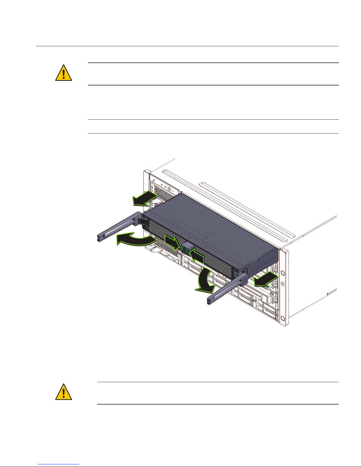
Remove the CPU modules from the front of the chassis.
The chassis contains four CPU module slots; each must have a CPU module or a ller panel.
Note – Because of their light weight, there is no need to remove ller panels.
For each CPU module:
a. Pinch the green tabs to release the ejectors (1).
b. Pull both ejectors out to release the module (2).
Caution – When the module is partway out of the chassis, close the ejectors, and grasp the
module. Do not handle the module by the ejectors.
2
2
3
1
1
3
2
Installing the Server In a Rack Using the Standard Rack MountingKit
27
c. Gently slide the module forward until it is clear of the chassis(3).
Caution – The CPU module is heavy. Use two hands.
d. Close the ejectors on the CPU module.
e. Place the CPU module on an antistatic mat.
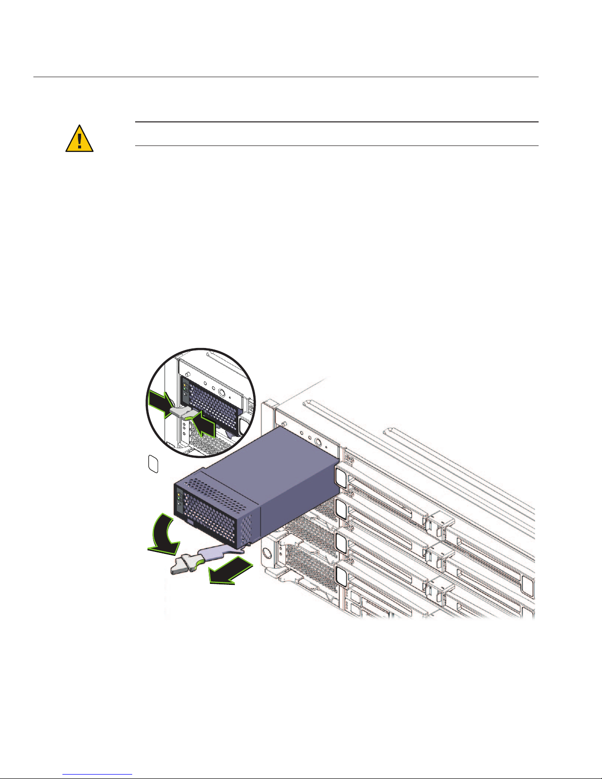
Remove the fourpower supplies from the front of the chassis.
a. Pinch the handle to release the lever (1).
b. Pull the lever (2)to release the power supply.
c. Slide the power supply out of the chassis (3).
Remove the PCIe express modules from the back of the chassis.
The upper bays can be used as a hand hold when moving the chassis.
2
3
1
1
3
4
Installing the Server In a Rack Using the Standard Rack MountingKit
Sun Fire X4800 Server Installation Guide • —12, March 201128
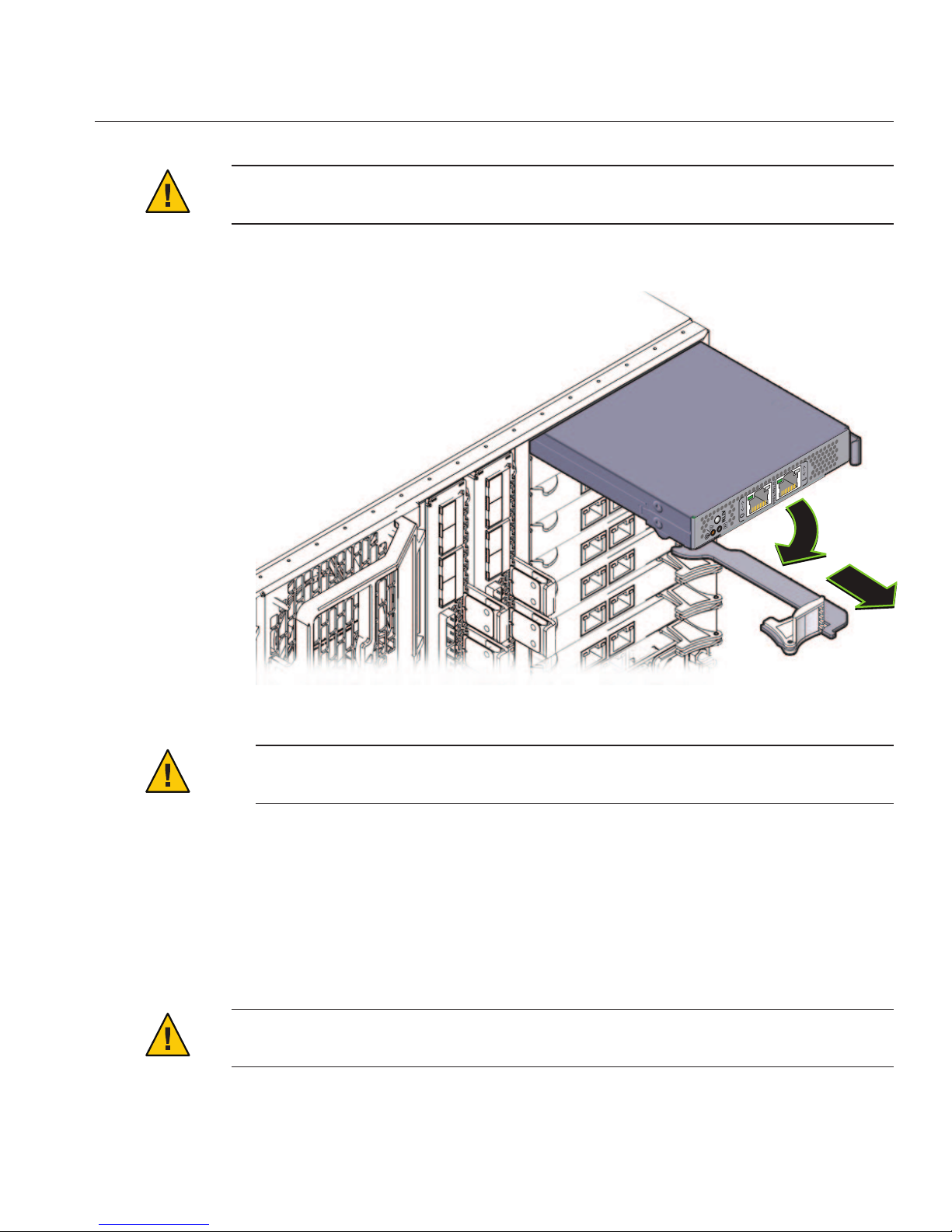
Caution – Do not insert forks from a lift device into these open bays, as this causes severe and
non-repairable damage.
a. Mark all PCIe EM cardswith their slot locations.
Caution – To prevent system failure, you must return PCIeEM cards to their original
locations. Mark PCIe EM slot locations carefully before removing them from the chassis.
b. Rotate the lever (1) to release the module.
c. Slide the module out of the chassis (2).
Remove the upperleft fan module (FM2) if necessary.
Squeeze the clamp (1) to release the fan module (2), then pull it from the chassis (3).
You can use the recess as a hand-hold when moving the chassis.
Caution – Do not insert forks from a lift device into this open bay, as this causes severe and
non-repairable damage.
1
2
5
Installing the Server In a Rack Using the Standard Rack MountingKit
29

“How to Replace the Components in the Server” on page 30
▼
How to Replace the Components in the Server
The procedure “How to Remove Components to Reduce Weight” on page 26 describes how to
remove components from the server. After the server is installed in the rack, you must replace
the components.
Reverse the steps in
“How to RemoveComponents to ReduceWeight”on page 26.
1
1
3
2
See Also
●
Installing the Server In a Rack Using the Standard Rack MountingKit
Sun Fire X4800 Server Installation Guide • —12, March 201130

Caution – All CPU modules and PCIe EM modules must be returned to their original locations.
Failure to do so can result in system failure.
▼
How to Install the Rack Mounting Hardware in Standard Rack
The rack mounting hardware consists of front and rear adapter brackets with cage nuts, screws,
and shelf rails.
Caution – The server weighs about 180 pounds (100 kg) when fully loaded with components. To
reduce the risk of serious personal injury or equipment damage, use a mechanical lift to install
the server into the rack. If a lift is not available, remove components as described in
“How to
Remove Components to Reduce Weight” on page 26
. This reduces the weight of the server to 80
pounds (45 kg).
Always load equipment into a rack from the bottom up so that it does not become top-heavy
and tip over. Deploy your rack’s anti-tilt bar to prevent the rack from tipping during equipment
installation.
Verify that you havea 5RU space in your rack.
Select the two front adapter brackets that match your rack.
See the following gure.
The server ships with two sets of front adapter brackets: one (1) for racks with square holes and
one (2) for racks with round holes. Select the adapter brackets that match your rack.
Attach the frontadapter brackets tothe rack.
Make sure you orient the adapter brackets correctly, with the arrow pointing up.
Select the screws that match your rack.
■
Use one M6 per side for a square-hole rack.
■
Use three M6 or three 10-32 per side for a threaded round-hole rack.
1
2
3
Installing the Server In a Rack Using the Standard Rack MountingKit
31

The following gure shows the front adapter brackets being attached to a square-hole rack (1)
and a round-hole rack (2).
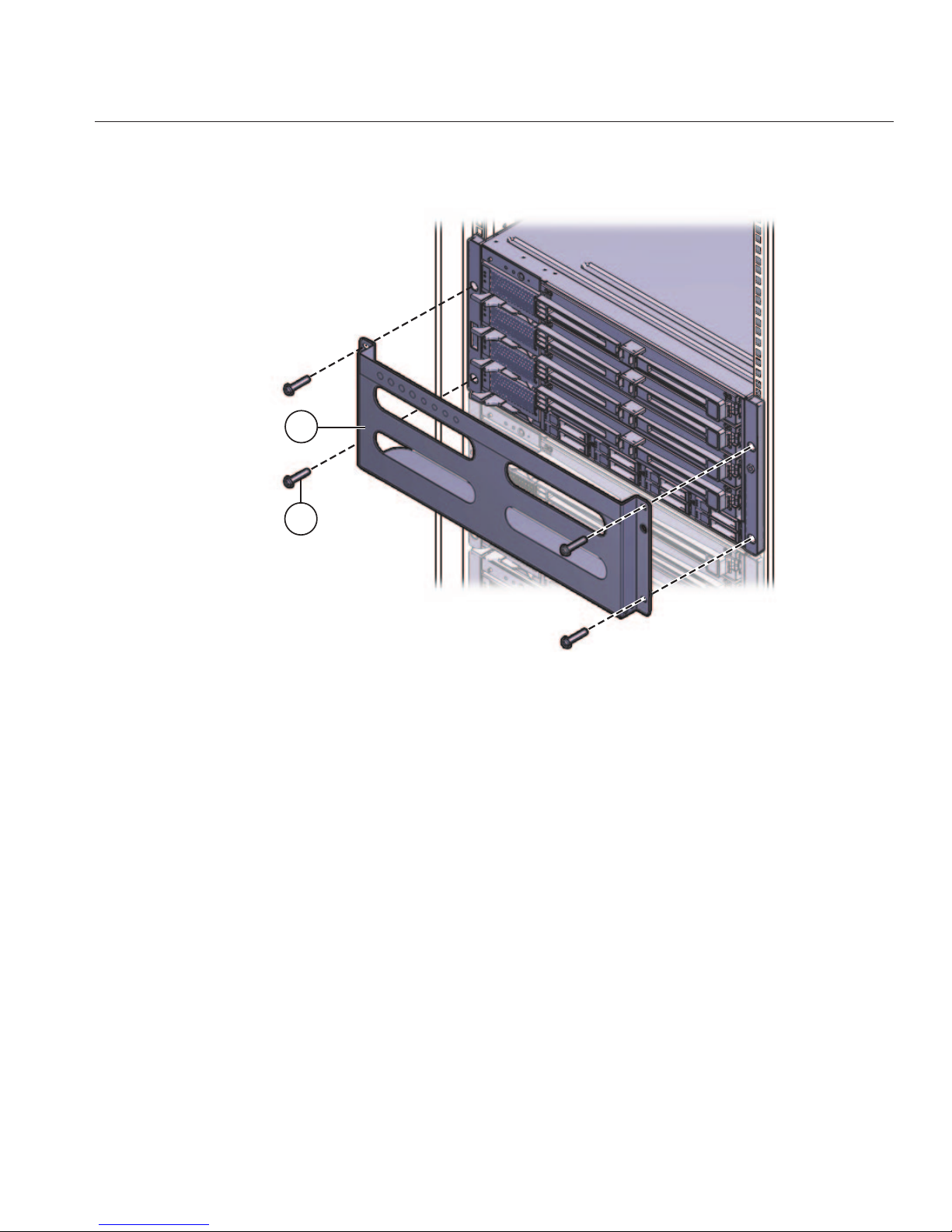
If your rack has round holes, use two screwseach (1) tofasten the two rear adapter brackets (2)
to the rack.
If your rack has square holes, skip this step.
1
2
1
2
4
Installing the Server In a Rack Using the Standard Rack MountingKit
Sun Fire X4800 Server Installation Guide • —12, March 201132

If your rackhas square holes:
a. Insert the cage nuts (1) for therear adapter bracketsin the holes on the rack.
b. If you are going to install shipping brackets, insert the cage nuts for the shipping brackets (2)
in the holes in the rear of the rack.
Note the orientation of the cage nuts for the shipping bracket.
■
They face outside the rack, in the opposite direction of the cage nuts for the adapter
brackets.
■
They are located in the rst and third holes above the cage nuts for the adapter brackets.
Note – If you are going to install shipping brackets so you can ship your system in a rack, and
your system has a square-hole rack, you must install the rear cage nuts for the shipping
bracket on the rack now, before installing the rear adapter bracket. You cannot add the cage
nuts for the rear shipping bracket when the rear adapter brackets are in place. See
“Removing and Installing the Standard Rack Mounting Kit Shipping Brackets” on page 39
for instructions to install the shipping brackets.
c. Use two screws(3) to fasten each rear adapter bracket (4) to the rack.
1
2
4
3
5
Installing the Server In a Rack Using the Standard Rack MountingKit
33

Place the shelf rails into the rack.
The following gure shows a square-hole rack.
The shelf rails expand (1) to t the rack, then slip into the slots on the adapter brackets (2), and
drop into place (3).
6
Installing the Server In a Rack Using the Standard Rack MountingKit
Sun Fire X4800 Server Installation Guide • —12, March 201134

Be certain to place the shelf rails in the proper orientation, with the shelf facing inward and the
gap towards the front of the rack.
“How to Insert the Server Into the Rack” on page 36
2
1
2
3
3
Next Steps
Installing the Server In a Rack Using the Standard Rack MountingKit
35

▼
How to Insert the ServerInto the Rack
The following procedure explains how to insert the server into the rack and on to the shelf rail
assemblies on the rack.
Perform the steps in
“How to Install the Rack Mounting Hardware in Standard Rack” on
page 31
.
Lift the server to its position on the rack.
The use of a lift is recommended.
Caution – The server weighs 180 pounds (82 kg). To reduce the risk of serious personal injury or
equipment damage, use a mechanical lift to install the server into the rack. If a lift is not
available, remove components as instructed in
“How to Remove Components to Reduce
Weight” on page 26
and use two persons to lift the server into place.
Slide the server onto the shelf rails.
Caution – Drop Hazard! Do not release the server until it is more than 6 inches (152 mm) into the
rack, and is rmly supported by the shelf rails. The shelf rails will not support the server until it
is more than 6 inches (152 mm) inside the rack.
Note – If the server is still on a pallet, you can leave it on the pallet and lift both the server and the
pallet with the mechanical lift, and slide the server o the pallet and onto the shelf rails.
BeforeYou Begin
1
2
Installing the Server In a Rack Using the Standard Rack MountingKit
Sun Fire X4800 Server Installation Guide • —12, March 201136

6”
(152mm)
!
!
!
Installing the Server In a Rack Using the Standard Rack MountingKit
37

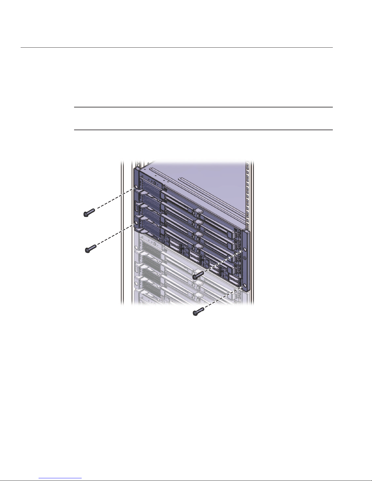
Use four screwsto attach the front of the server to the frontof the rack.
Use either the M6 x 25, or the 10-32 x 1 screws.
■
On a threaded rack, use four M6 x 25, or four 10-32 x 1 screws.
■
On a square-hole rack, use four M6 x 25 screws.
If you removedcomponents from the server,replace them afterit is mounted in the rack. See
“How to RemoveComponents to ReduceWeight”on page 26.
■
“How to Remove the Server From the Rack” on page 85
■
“Cabling and Power” on page 91
■
“How to Remove Components to Reduce Weight” on page 26
3
4
See Also
Installing the Server In a Rack Using the Standard Rack MountingKit
Sun Fire X4800 Server Installation Guide • —12, March 201138

Removing and Installing the Standard Rack Mounting Kit
Shipping Brackets
If the server is shipped in a rack, it must be supported by shipping brackets.
■
If the server is shipped to you in a rack, you must remove the shipping brackets before
placing it in service. See
“How to Remove the Standard Rack Mounting Kit Shipping
Brackets ” on page 39
.
■
If you plan to ship the server in a rack, see “How to Install the Standard Rack Mounting Kit
Shipping Brackets” on page 41
.
The shipping bracket parts are in the accessory tray with the rack mounting hardware. See
“Location of the Rack Mounting Kit and the Shipping Bracket Kit” on page 25 for details.
▼
How to Remove the Standard Rack Mounting Kit Shipping Brackets
This procedure describes how to remove brackets from a system equipped with the standard
rack mounting kit.
The shipping bracket kit consists of a front bracket, a rear bottom bracket, a rear top bracket,
screws to connect them to the rack, and cage nuts to be used with the rear brackets on racks with
square holes. These appear in
“How to Install the Standard Rack Mounting Kit Shipping
Brackets” on page 41
.
Removing and Installing the Standard Rack Mounting Kit Shipping Brackets
39

Remove the fourscrews (1) thatfasten the front shipping bracket (2) to thefront of the server
and remove it.
The front shipping bracket contains eight threaded holes used for storing unused screws (four
M6 and four 10–32). Remove the screws that match the threads on your rack and use them to
secure the server to therack.
There might be two sets of screws stored on the front of the shipping bracket. Use the set that
matches the threading on your rack.
Thread the long screws that youremoved in Step 1 into the four empty holes on the shipping
bracket.
They will be stored there in case you need to reinstall the shipping bracket.
Remove the fourscrews (1) thatfasten the rear top shipping bracket (2) over the back ofthe
server and remove it.
1
2
1
2
3
4
Removing and Installing the Standard Rack Mounting Kit Shipping Brackets
Sun Fire X4800 Server Installation Guide • —12, March 201140

Remove the fourscrews (3) thatfasten the rear bottom shipping bracket (4) under the back of
the server and remove it.
▼
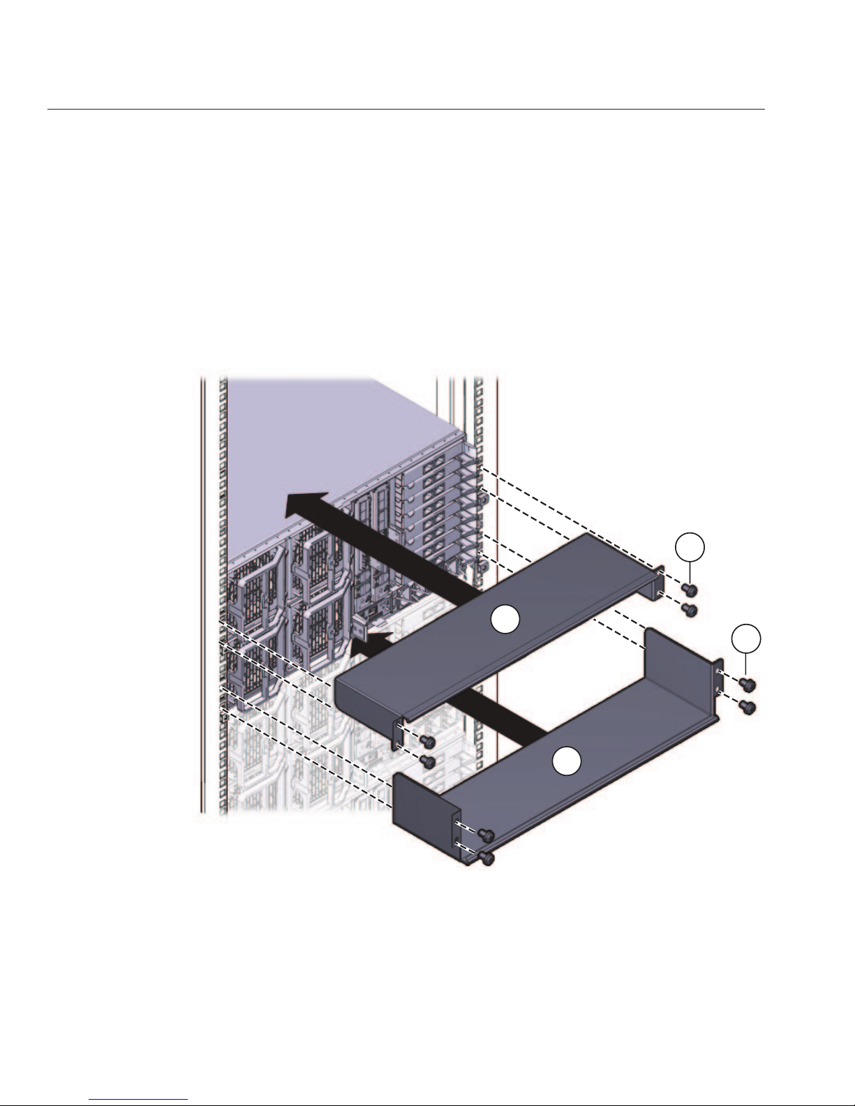
How to Install the Standard Rack Mounting Kit Shipping Brackets
This procedure describes how to install brackets into a system equipped with the standard rack
mounting kit.
The shipping bracket kit contains the following parts:
1
4
2
3
5
Removing and Installing the Standard Rack Mounting Kit Shipping Brackets
41

Figure Legend
1 Front shipping bracket
2, 3 Two sets of screws (M6 and 10-32). Each set contains four screws for the front shipping
bracket (2) and eight screws for the rear shipping brackets (5 and 6)
4 Eight M6 cage nuts for rear shipping bracket in square-hole racks
5 Top rear shipping bracket
6 Bottom rear shipping bracket
Note – The shipping bracket kit is shipped in the accessory tray with the rack mounting kit. See
“Location of the Rack Mounting Kit and the Shipping Bracket Kit” on page 25 for details.
Remove the four(short) screwsthat fasten the front of the server to the rack.
Insert the front shipping bracket (1) into the front ofthe serverwith the supporting ange
underneath the server.
The front shipping bracket contains eight threaded holes used for storing unused screws (four
M6 and four 10–32). Remove the long screwsthat match the threads on yourrack.
3
4
2
1
6
5
1
2
3
Removing and Installing the Standard Rack Mounting Kit Shipping Brackets
Sun Fire X4800 Server Installation Guide • —12, March 201142
Use the four long screws (M6 or 10–32) (1) to fasten the shipping bracket (2) to the front of the
server.
Insert the short screwsinto the four empty storage holes on the shipping bracket.
They will be stored there to be used when you remove the shipping bracket.
If you areinstalling the shipping brackets in a rack with square holes, check to ensure that the
cage nuts are installed in the rear.
Note the orientation and location of the cage nuts for the shipping bracket.
■
There are four cage nuts per side (eight total).
■
They are installed on the inside of the rack, facing outward. This is the opposite direction
from the cage nuts for the shelf adapter brackets.
■
For each shipping bracket, there should be two shipping bracket cage nuts; one in the hole
directly above the shipping bracket cage nut, and one in the third hole above the shipping
bracket cage nut.
If the cage nuts are not in place, you must:
a. Remove the server and the mounting hardware from the rack, as described in
“Removing
the ServerFromthe Rack”on page 85
.
1
2
4
5
6
Removing and Installing the Standard Rack Mounting Kit Shipping Brackets
43
b. Reinstall the adapter bracketsand the server, andinstall the rear shipping bracketcage nuts
as you install the rear adapter brackets. This is included in the rack mounting procedure.
See
“How to Install the Rack Mounting Hardware in Standard Rack” on page 31.
Insert the rear top shipping bracket (1) overthe back of the server with the side panels facing
down.
Use four screws (2) to fasten it to the rack (4).
Insert the rear bottom shipping bracket (3) under the back of the server with the side panels
facing up.
Use four screws (4) to fasten it to the rack.
1
2
3
4
7
8
Removing and Installing the Standard Rack Mounting Kit Shipping Brackets
Sun Fire X4800 Server Installation Guide • —12, March 201144

Installing the Server In the Rack Using the
Universal Rack Mounting Kit
This topic describes how to install your server in a rack using the universal rack mounting
hardware.
If you are not certain whether you have the standard rack mounting kit or the universal rack
mounting kit, see
“How to Identify Your Rack Mounting Kit” on page 17, then proceed to the
corresponding section.
Note the following:
■
If your server is shipped already installed in a rack, skip to “How to Remove the Universal
Rack Mounting Kit Shipping Brackets” on page 80
.
■
If you are going to ship the server in a rack, you must install the shipping brackets as
described in
“How to Install the Universal Rack Mounting Kit Shipping Brackets” on
page 76
.
This section contains the following topics:
■
“Contents of the Universal Rack Mounting Kit” on page 47
■
“Installing the Server in a Rack Using the Universal Rack Mounting Kit” on page 49
■
“Installing and Removing the Universal Rack Mounting Kit Shipping Brackets” on page 76
Tools and Sta Required
Caution – The server weighs about 180 pounds (100 kg) when fully loaded with components. To
reduce the risk of serious personal injury or equipment damage, use a mechanical lift to install
the server into the rack. If a lift is not available, remove components as described in
“How to
Remove Components to Reduce Weight” on page 26
. This reduces the weight of the server to 80
pounds (45 kg).
Always load equipment into a rack from the bottom up so that it does not become top-heavy
and tip over. Deploy your rack’s anti-tilt bar to prevent the rack from tipping during equipment
installation.
Before installing the server into a rack, gather the tools, equipment, and sta required.
45

Tools,Equipment, and Stang Required Notes
Two trained sta Two people are needed to install the server and operate the lift.
No. 2 10-inch Phillips screwdriver
(magnetic tip recommended)
Mechanical lift Strongly recommended. If not available, reduce the weight of the
server. See
“How to Remove Components to Reduce Weight” on
page 26
.
Compatible rack See
“Compatible Racks ” on page 46.
Rack mounting kit See
“Installing the Server in a Rack Using the Universal Rack
Mounting Kit” on page 49
.
Shipping brackets See
“Installing and Removing the Universal Rack Mounting Kit
Shipping Brackets” on page 76
.
■
You must remove the shipping brackets if your server was shipped
in a rack.
■
You must install the shipping brackets if you plan to ship your
server in a rack.
Installing Optional Equipment
For information about how to install options such as DIMMs, PCIe EMs, and NEMs, power
supplies, and CPU modules, refer to the
Sun Fire X4800 Server Service Manual.
For information about issues and known workarounds, refer to the
Sun Fire X4800 Server
Product Notes
.
Compatible Racks
The rack mounting hardware is compatible with a wide range of equipment racks that meet the
following standards:
■
Four-post rack (mounting at both front and rear).
Note – Two-post racks are not compatible.
■
Rack must have 5RU space available.
■
Rack should have a horizontal opening and unit vertical pitch conforming to ANSI/EIA
310-D-1992 or IEC 60927 standards.
■
Distance between front and rear mounting planes between approximately 26 and 34.5
inches (660.4 mm and 876.3 mm).
Installing Optional Equipment
Sun Fire X4800 Server Installation Guide • —12, March 201146

■
Minimum clearance depth (to front cabinet door) in front of front rack mounting plane: 1
inch (25.4 mm).
■
Minimum clearance depth (to rear cabinet door) behind front rack mounting plane: 27.5
inches (700 mm).
■
Minimum clearance width (between structural supports and cable troughs) between front
and rear mounting planes: 18 inches (456 mm).
Contents of the Universal Rack Mounting Kit
The universal rack mounting kit comes with the following hardware:
Contents of the Universal Rack Mounting Kit
47

Figure Legend
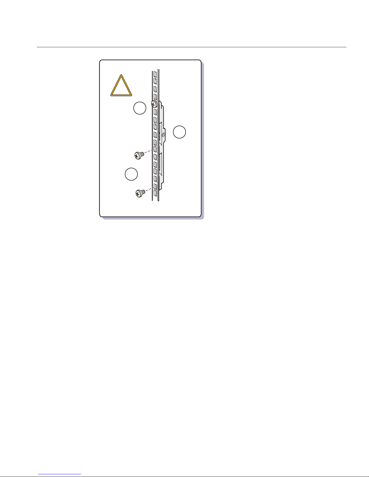
1 Top rear braces These attach to the posts at the upper back of the server.
2, 3 Left (2) and right (3) shelf rails Once the front and rear adapter brackets are installed on the
rack, the shelf rails drop into place. The hooks on the rails
hook into the slots on the front and rear brackets.
The shelf rails expand to match the depth of the rack.
These are not slide rails. Once the server is mounted in the
chassis, it does not move.
2
1
3
4
6
5
Contents of the Universal Rack Mounting Kit
Sun Fire X4800 Server Installation Guide • —12, March 201148

Figure Legend
4 An assortment of M6 and 10-32
screws
The screws are packaged by size and
type. They include:
■
12–M6X16
■
12–M6X12
■
4 – M6 X 4 athead
■
4 – 10-32 X 10
■
12 – 10-32 shoulder screws
Oracle provides extra screws to support dierent
congurations. Unused hardware can be discarded or
recycled when you have completed the installation.
5 Adapter brackets (2 sets of four each) These attach to the rack and support the shelf rails.
There are two sets of adapter brackets; one for round-hole
racks, and another for square-hole racks. Use the set that
matches your rack.
6 M6 cage nuts Used to attach the top rear braces to square-hole racks.
Installing the Server in a Rack Using the Universal Rack
Mounting Kit
This section provides instructions for installing your server in a rack. It includes:
■
“How to Remove Components to Reduce Weight” on page 49
■
“How to Replace the Components in the Server” on page 54
■
“How to Install the Rack Mounting Hardware in a Square-Hole Rack” on page 55
■
“How to Install the Rack Mounting Hardware in a Round-Hole Rack” on page 64
■
“How to Insert the Server Into the Rack” on page 72
Note – The rack mounting kit does not include slide rails. Once the server is installed, it does not
slide in or out of the rack.
▼
How to Remove Components to Reduce Weight
This procedure describes how to remove components from your server so that two persons can
lift it into the rack. If you are going to use a mechanical lift, you do not need to perform this
procedure.
Installing the Server ina Rack Using the Universal Rack MountingKit
49

Caution – Circuit boards and hard drives contain electronic components that are extremely
sensitive to static electricity. Ordinary amounts of static electricity from clothing or the work
environment can destroy the components located on these devices. Do not touch the
components without antistatic precautions, especially along the connector edges. For more
information, refer to
“Antistatic Precautions and Procedures” in Sun Fire X4800 Server Service
Manual
.
Note – This procedure assumes that the server is powered o and all cables are disconnected.
Mark all CPU modules with their slot numbers.
Caution – To prevent system failure, you must return CPU modules to their original locations.
Mark CPU module slot locations carefully before removing them from the chassis.
Remove the CPU modules from the front of the chassis.
The chassis contains four CPU module slots; each must have a CPU module or a ller panel.
Note – Because of their light weight, there is no need to remove ller panels.
BeforeYou Begin
1
2
Installing the Server ina Rack Using the Universal Rack MountingKit
Sun Fire X4800 Server Installation Guide • —12, March 201150

For each CPU module:
a. Pinch the green tabs to release the ejectors (1).
b. Pull both ejectors out to release the module (2).
Caution – When the module is partway out of the chassis, close the ejectors, and grasp the
module. Do not handle the module by the ejectors.
c. Gently slide the module forward until it is clear of the chassis(3).
Caution – The CPU module is heavy. Use two hands.
d. Close the ejectors on the CPU module.
e. Place the CPU module on an antistatic mat.
2
2
3
1
1
3
Installing the Server ina Rack Using the Universal Rack MountingKit
51

Remove the fourpower supplies from the front of the chassis.
a. Pinch the handle to release the lever (1).
b. Pull the lever torelease the powersupply (2).
c. Slide the power supply out of the chassis (3).
Remove the PCIe express modules from the back of the chassis.
The upper bays can be used as a hand hold when moving the chassis.
Caution – Do not insert forks from a lift device into these open bays, as this causes severe and
non-repairable damage.
2
3
1
1
3
4
Installing the Server ina Rack Using the Universal Rack MountingKit
Sun Fire X4800 Server Installation Guide • —12, March 201152

a. Mark all PCIe EM cardswith their slot locations.
Caution – To prevent system failure, you must return PCIeEM cards to their original
locations. Mark PCIe EM slot locations carefully before removing them from the chassis.
b. Rotate the lever to release the module (1).
c. Slide the module out of the chassis (2).
Remove the upperleft fan module (FM2) if necessary.
Squeeze the clamp (1) to release the fan module (2), then pull it from the chassis (3).
You can use the recess as a hand-hold when moving the chassis.
Caution – Do not insert forks from a lift device into this open bay, as this causes severe and
non-repairable damage.
1
2
5
Installing the Server ina Rack Using the Universal Rack MountingKit
53

“How to Install the Rack Mounting Hardware in a Square-Hole Rack” on page 55
“How to Install the Rack Mounting Hardware in a Round-Hole Rack” on page 64
“How to Replace the Components in the Server” on page 54
▼
How to Replace the Components in the Server
The procedure “How to Remove Components to Reduce Weight” on page 49 describes how to
remove components from the server. After the server is installed in the rack, you must replace
the components.
Reverse the steps in
“How to RemoveComponents to ReduceWeight”on page 49.
1
1
3
2
See Also
●
Installing the Server ina Rack Using the Universal Rack MountingKit
Sun Fire X4800 Server Installation Guide • —12, March 201154

Caution – All CPU modules and PCIe EM modules must be returned to their original locations.
Failure to do so can result in system failure.
▼
How to Install the Rack Mounting Hardware in a Square-HoleRack
The rack mounting kit consists of adapter brackets, rear braces, shelf rails, cage nuts, and
screws.
Caution – The server weighs about 180 pounds (100 kg) when fully loaded with components. To
reduce the risk of serious personal injury or equipment damage, use a mechanical lift to install
the server into the rack. If a lift is not available, remove components as described in
“How to
Remove Components to Reduce Weight” on page 49
. This reduces the weight of the server to 80
pounds (45 kg).
Always load equipment into a rack from the bottom up so that it does not become top-heavy
and tip over. Deploy your rack’s anti-tilt bar to prevent the rack from tipping during equipment
installation.
Note – To install rack mounting hardware in round-hole racks, see “How to Install the Rack
Mounting Hardware in a Round-Hole Rack” on page 64
.
This task requires the following screws and connectors:
Function Description
Attach adapter brackets to front rack posts Four M6 x 12
Attach adapter brackets to rear rack posts Four M6 x 12
Attach braces to rear rack posts Four M6 x 10
and four M6 cage nuts
Locking screws for rails Four M4 x 10 athead
Gather the following screws and connectors:
Verify that you havea 5RU space in your rack.
Select the set of adapter brackets for square-hole racks.
The server ships with two sets of adapter brackets: one for racks with square holes (1) and one
for racks with round holes (2). The brackets for square-hole racks (1) have threads. See the
following gure.
1
2
3
Installing the Server ina Rack Using the Universal Rack MountingKit
55

Note – Arrows on the brackets (3) indicate how the bracket should be oriented. Be sure to install
all brackets with the “Top” arrow (3) pointing up.
Installing the Server ina Rack Using the Universal Rack MountingKit
Sun Fire X4800 Server Installation Guide • —12, March 201156

1
2
3
Installing the Server ina Rack Using the Universal Rack MountingKit
57

Attach the bracketsto the front posts.
Place the brackets so that the bottom of the bracket is aligned with the bottom of the (5RU)
space where the server will go, and that the arrow labelled “top” points up.
Note – The accessory tray includes a printed template that you can use to help align the adapter
brackets.
Use one M6 x 16 screw per side. Pass the screw from the outside of the rack, through the holes in
the post, and into the threads on the adapter brackets.
The other two holes (per side) are used later, to attach the bezel of the server to the rack.
Attach the bracketsto the rear posts.
Place the brackets so that the bottom of the bracket is aligned with the bottom of the (5RU)
space where the server will go, and that the arrow labelled “top” points up.
4
5
Installing the Server ina Rack Using the Universal Rack MountingKit
Sun Fire X4800 Server Installation Guide • —12, March 201158

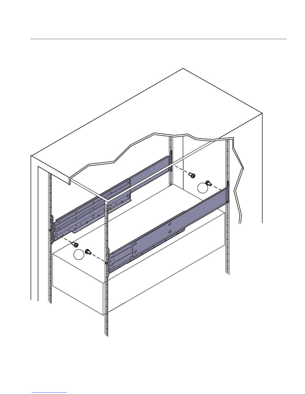
Use three M6 X 16 screws per side (1) to fasten the bracket (2) to the posts (3).
Attach upper rearbraces (1) to the rack posts (2) directly above the adapter brackets, as shown
in the following gure.
Install two M6 cage nuts (4) per side and then use two M6 x 16 screws (3).
1
2
3
6
Installing the Server ina Rack Using the Universal Rack MountingKit
59

Before tightening the screws, slide the braces (1) up as far as they will go. The holes on the
braces are oval-shaped so they can move a little up and down when the screws are loose.
1
2
4
2
3
1
4
3
Installing the Server ina Rack Using the Universal Rack MountingKit
Sun Fire X4800 Server Installation Guide • —12, March 201160

Remove the six screws (1) that hold the left and right shelf extenders (2) on the shelf rails (3),
and then removethe shelf extenders.
You must remove the shelf extenders before installing the server in the rack. They are used for
other products.
1
2
2
3
3
7
Installing the Server ina Rack Using the Universal Rack MountingKit
61
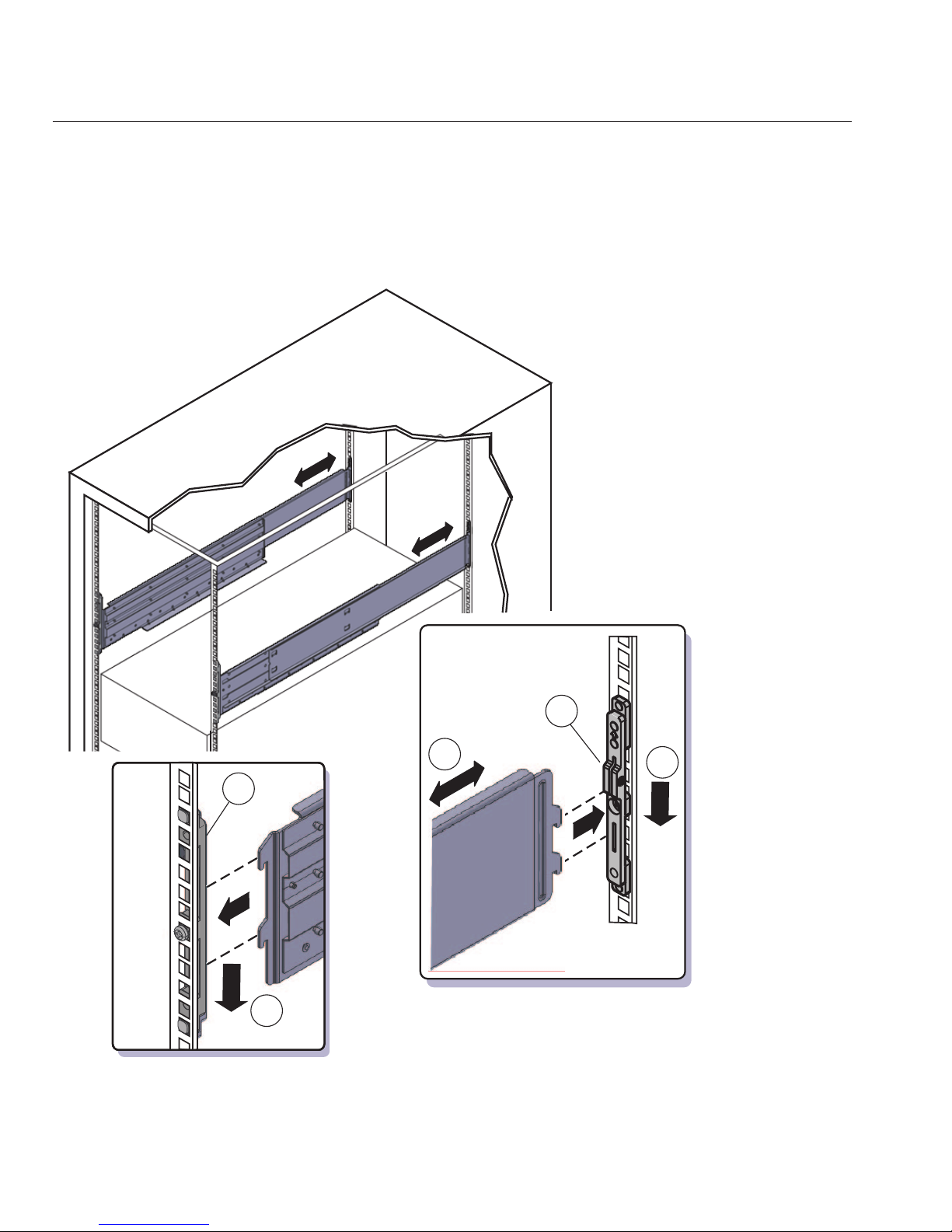
Place the shelf rails into the rack.
The shelf rails expand (1) to t the rack, then slip into the slots on the adapter brackets (2), and
drop into place (3).
Be certain to place the shelf rails in the proper orientation. They are labelled “FRONT LEFT”
and “FRONT RIGHT”.
2
2
1
3
3
8
Installing the Server ina Rack Using the Universal Rack MountingKit
Sun Fire X4800 Server Installation Guide • —12, March 201162

Thread the fourM4 X 10 athead locking screws (1) into the adapterbrackets.
These prevent the shelf rails from accidentally lifting out of the adapter brackets.
1
1
9
Installing the Server ina Rack Using the Universal Rack MountingKit
63

“How to Insert the Server Into the Rack” on page 72
▼
How to Install the Rack Mounting Hardware in a Round-Hole Rack
The rack mounting kit consists of adapter brackets, rear braces, shelf rails, cage nuts, and
screws.
Caution – The server weighs about 180 pounds (100 kg) when fully loaded with components. To
reduce the risk of serious personal injury or equipment damage, use a mechanical lift to install
the server into the rack. If a lift is not available, remove components as described in
“How to
Remove Components to Reduce Weight” on page 49
. This reduces the weight of the server to 80
pounds (45 kg).
Always load equipment into a rack from the bottom up so that it does not become top-heavy
and tip over. Deploy your rack’s anti-tilt bar to prevent the rack from tipping during equipment
installation.
Note – To install rack mounting hardware in square-hole racks, see “How to Install the Rack
Mounting Hardware in a Square-Hole Rack” on page 55.
This task uses the following screws and connectors:
Function Description for M6 Racks Description for 10-32 Racks
Attach adapter brackets to front rack posts Four M6 x 12 Four 10-32 x 10
Attach adapter brackets to rear rack posts Four M6 x 12 Four 10-32 shoulder screws
Attach braces to rear rack posts Four M6 x 10 Four 10-32 x 10
Locking screws for rails Four M4 x 10 athead Four M4 x 10 athead
Verify that you havea 5RU space in your rack.
Select the set of adapter brackets for round-hole racks.
The server ships with two sets of adapter brackets: one for racks with square holes (1), and one
for racks with round holes (2). The adapter brackets for square-hole racks (1) have threads. The
adapter brackets for round-hole (tapped) racks (2) do not. See the following gure.
Note – Arrows on the adapter brackets (3) indicate how they should be oriented. Be sure to
install all brackets with the “Top” arrow (3) pointing up.
Next Steps
1
2
Installing the Server ina Rack Using the Universal Rack MountingKit
Sun Fire X4800 Server Installation Guide • —12, March 201164

1
2
3
Installing the Server ina Rack Using the Universal Rack MountingKit
65

Attach the adapter brackets to the front posts.
Place the adapter brackets so that the bottom of the adapter bracket is aligned with the bottom
of the (5RU) space where the server will go, and that the arrow labelled “top” points up.
Use three M6 x 12 or 10-32 x 10 screws for each side. Pass the screws from the inside of the rack,
through the adapter bracket, and into the threads on the post.
Note – The accessory box includes a printed template that you can use to help align the adapter
brackets.
Attach the adapter brackets to the rear posts.
Place the adapter brackets so that the bottom of the adapter bracket is aligned with the bottom
of the (5RU) space where the server will go, and that the arrow labelled “top” points up.
Pass two screws (1) from the inside of the rack, through the top and bottom holes in the adapter
bracket (2), and thread them into the post (3).
Note – Do not use the center screw in the adapter bracket. It is reserved for the optional shipping
bracket kit described in
“Installing and Removing the Universal Rack Mounting Kit Shipping
Brackets” on page 76
.
■
For M6 racks, use two M6 x 12 screws per side.
■
For 10-32 racks, use two 10-32 shoulder screws per side.
3
4
Installing the Server ina Rack Using the Universal Rack MountingKit
Sun Fire X4800 Server Installation Guide • —12, March 201166

Attach upper rearbraces (1) to the rack posts (2) directly above the adapter brackets, as shown
in the following gure.
Use either two M6 x 16 or two 10-32 x 10mm screws (3) per side.
1
2
3
1
5
Installing the Server ina Rack Using the Universal Rack MountingKit
67

Before tightening the screws, slide the braces (1) up as far as they will go. The holes on the
braces are oval-shaped so they can move a little up and down when the screws are loose.
3
1
1
3
2
2
Installing the Server ina Rack Using the Universal Rack MountingKit
Sun Fire X4800 Server Installation Guide • —12, March 201168

Remove the six screws (1) that hold the left and right shelf extenders (2) on the shelf rails (3),
and then removethe shelf extenders.
You must remove the shelf extenders before installing the server in the rack. They are used for
other products.
1
2
2
3
3
6
Installing the Server ina Rack Using the Universal Rack MountingKit
69

Place the shelf rails into the rack.
The shelf rails expand (1) to t the rack, then slip into the slots on the adapter brackets (2), and
drop into place (3).
Be certain to place the shelf rails in the proper orientation. They are labelled “FRONT LEFT”
and “FRONT RIGHT”.
2
2
1
3
3
7
Installing the Server ina Rack Using the Universal Rack MountingKit
Sun Fire X4800 Server Installation Guide • —12, March 201170
Thread the fourM4 X 10 athead locking screws (1) into the adapterbrackets.
These prevent the shelf rails from accidentally lifting out of the adapter brackets.
1
1
8
Installing the Server ina Rack Using the Universal Rack MountingKit
71

“How to Insert the Server Into the Rack” on page 72
▼
How to Insert the ServerInto the Rack
The following procedure explains how to insert the server into the rack and on to the shelf rail
assemblies in the rack.
Perform the steps in
“How to Install the Rack Mounting Hardware in a Round-Hole Rack” on
page 64
.
Lift the server to its position in the rack.
The use of a mechanical lift is recommended.
Caution – The server weighs 180 pounds (82 kg). To reduce the risk of serious personal injury or
equipment damage, use a mechanical lift to install the server into the rack. If a lift is not
available, remove components as instructed in
“How to Remove Components to Reduce
Weight” on page 49
and use two persons to lift the server into place.
Slide the server onto the shelf rails.
Caution – Drop Hazard! Do not release the server until the rear of the server is more than 6 inches
(152 mm) into the rack, and is rmly supported by the shelf rails. The shelf rails will not support
the server until it is more than 6 inches (152 mm) inside the rack.
Note – If the server is still on a pallet, you can leave it on the pallet and lift both the server and the
pallet with the mechanical lift, and slide the server o the pallet and onto the shelf rails.
Next Steps
BeforeYou Begin
1
2
Installing the Server ina Rack Using the Universal Rack MountingKit
Sun Fire X4800 Server Installation Guide • —12, March 201172

6”
(152mm)
!
!
!
Installing the Server ina Rack Using the Universal Rack MountingKit
73
Use four screwsto attach the front bezel of the server to the front of the rack, as shown in the
following gure.
■
For square-hole racks, use four M6 x 16 screws.
■
For round-hole racks, use four M6 x 12, or four 10-32 x 10 screws.
Note – On square-hole racks, the screws pass through the rack and thread into the adapter
bracket. On round-hole racks, the screws thread into to the rack rails.
Move the rearbraces so they are snug against the server chassis. See the following gure.
From the rear of the system:
a. Loosen the screws(1).
b. Slide the braces down(2).
c. Tighten the screws(1).
3
4
Installing the Server ina Rack Using the Universal Rack MountingKit
Sun Fire X4800 Server Installation Guide • —12, March 201174

1
1
2
2
Installing the Server ina Rack Using the Universal Rack MountingKit
75

If you removedcomponents from the server,replace them afterit is mounted in the rack. See
“How to RemoveComponents to ReduceWeight”on page 49.
■
“How to Remove the Server From the Rack” on page 85
■
“Cabling and Power” on page 91
■
“How to Remove Components to Reduce Weight” on page 49
Installing and Removing the Universal Rack Mounting Kit
Shipping Brackets
If the server is shipped in a rack, it must be supported by shipping brackets.
■
If the server is shipped to you in a rack, you must remove the front brackets before placing it
in service. Removing the rear brackets is optional. See
“How to Remove the Universal Rack
Mounting Kit Shipping Brackets” on page 80
.
■
If you plan to ship the server in a rack, see “How to Install the Universal Rack Mounting Kit
Shipping Brackets” on page 76
.
If you have ordered a server with shipping brackets, they are shipped in the accessory tray.
▼
How to Install the Universal Rack Mounting Kit Shipping Brackets
This procedure describes how to install brackets into a system equipped with the universal rack
mounting kit.
The following picture shows the shipping bracket kit.
5
See Also
Installing and Removing the Universal Rack Mounting Kit Shipping Brackets
Sun Fire X4800 Server Installation Guide • —12, March 201176

Figure Legend
1 Front shipping bracket
2 Screws and cage nuts. The kit contains two sets of screws (M6 and 10-32), plus cage
nuts. The cage nuts are not used for the Sun Fire X4800 server.
3 Bottom rear shipping bracket
Remove the two(short) screwsthat fasten thebottom of the bezel to the rack.
Insert the front bracket (2) into the front of theserver with the supportingange underneath
the server.
See the gure below.
Use the two long screws (M6 x 25or 10-32 x 1) (1) to fasten the shipping bracket(2) to the front
of the server.
1
2
3
1
2
3
Installing and Removing the Universal Rack Mounting Kit Shipping Brackets
77

Note – The front shipping bracket includes eight threaded holes (3) used for storing unused
screws. When the shipping brackets are not installed, it holds the long screws used to install
them. When the shipping brackets are installed, it stores the short screws that were used before
the shipping brackets were installed.
Insert the short screwsinto the empty storage holes on the shipping bracket.
They will be stored there to be used when you remove the shipping bracket.
For square-hole racks,remove the bottom screws (1) that hold the rear adapter brackets (2) in
place. See the following gure.
Caution – Do not remove the bottom screws unless you are certain that the upper screw (3) is in
place. Otherwise, the server could fall.
1
2
3
1
4
5
Installing and Removing the Universal Rack Mounting Kit Shipping Brackets
Sun Fire X4800 Server Installation Guide • —12, March 201178
Insert the rear bottom bracket(1) under the back of the serverwith the side panels facing up, as
shown in the following gure.
Use four screws (2) to fasten it to the rack. Do not nish tightening these screws. They should be
tight enough to hold the bracket in place, but you should still be able to move the bracket
slightly.
■
For square-hole racks, use the two screws that you removed in Step 5.
■
For round-hole racks, use either 10-32 x 10 or M6 x 12.
1
2
3
!
6
Installing and Removing the Universal Rack Mounting Kit Shipping Brackets
79

The bracket should be fastened to the posts, but loose enough to move slightly.
Push the bracketup so that it restsrmly against the bottom of the server, then nishing
tightening the screwsthat hold the bracket in place.
If necessary, loosen the screws enough so that you can move the bracket, then tighten them after
pushing it against the bottom of the server.
Caution – To prevent damage to the server during shipping, the bottom shipping bracket must
rest rmly against the bottom of the server.
▼
How to Remove the Universal Rack Mounting Kit Shipping Brackets
This procedure describes how to remove brackets from a system equipped with the universal
rack mounting kit.
7
Installing and Removing the Universal Rack Mounting Kit Shipping Brackets
Sun Fire X4800 Server Installation Guide • —12, March 201180

The shipping bracket kit consists of a front bracket, a rear bottom bracket, and screws to
connect them to the rack. These appear in
“How to Install the Universal Rack Mounting Kit
Shipping Brackets” on page 76
.
Remove the twoscrews (1) thatfasten the front bracket (2) to the frontof the server and remove
it.
1
2
1
2
1
Installing and Removing the Universal Rack Mounting Kit Shipping Brackets
81

Find the screwsfrom the frontof shipping bracket that match your rack and use them to fasten
the bezel into the rack.
The front shipping bracket contains eight threaded holes used for storing unused screws (four
M6 and four 10-32). Remove the screws that match the threads on your rack and use them to
secure the server to the rack.
Thread the long screws that youremoved in Step 2 into the matching empty holes on the
shipping bracket.
They will be stored there in case you need to reinstall the shipping bracket.
1
1
2
3
Installing and Removing the Universal Rack Mounting Kit Shipping Brackets
Sun Fire X4800 Server Installation Guide • —12, March 201182

Remove the fourscrews (1) thatfasten the rear bottom bracket (2) under the back of the server
and remove it.
Replace the four screws that youremoved in Step 4.
1
2
1
4
5
Installing and Removing the Universal Rack Mounting Kit Shipping Brackets
83

84

Removing the Server From the Rack
■
“How to Remove the Server From the Rack” on page 85
■
“How to Remove the Rack Mounting Hardware from the Rack” on page 88
▼
How to Remove the Server From the Rack
This procedure assumes that you have turned o the server, and removed any cables or cords
that would restrict the movement of the server.
Caution – The Sun Fire X4800 server weighs about 180 pounds (100 kg) when fully loaded with
components. To reduce the risk of serious personal injury or equipment damage, use a
mechanical lift to remove the sever from the rack. If a mechanical lift is not available, remove
components to reduce weight and use two persons to lift it.
Disconnect all cables from the rear of the system.
If a lift is not available, remove components to reduce the system’s weight.See
“How to Remove
Components to ReduceWeight” on page 49
.
BeforeYou Begin
1
2
85

Remove the fourscrews from the front bezel of the system.
Using two hands,slide the server toward yourself and remove it from the shelf rails.
Caution – Drop hazard. The shelf rails release the weight of the server when it is within 6 inches
of being clear of the rack. You must support the weight of the server before it is within 6 inches
of being clear of the rack posts.
3
4
Removing the Server From the Rack
Sun Fire X4800 Server Installation Guide • —12, March 201186

6”
(152mm)
!
!
Removing the Server From the Rack
87

“How to Insert the Server Into the Rack” on page 72
▼
How to Remove the Rack Mounting Hardware from
the Rack
This task shows how to remove the rack mounting hardware from the universal rack and from
the standard rack. This task is similar for each; however the universal rack is shown.
In this procedure, the dierences between the universal rack and the standard rack are trivial,
except where they are noted.
Remove the fourlocking screws (1).
Perform this step for the universal rack mounting kit only. The standard rack mounting kit does
not include these screws.
See the following gure.
Lift the two shelf rails (2) to disengage the hooks from the adapter brackets.
You can compress the shelf rails once you have disengaged the hooks from the adapter brackets.
See Also
1
2
Removing the Server From the Rack
Sun Fire X4800 Server Installation Guide • —12, March 201188

Remove the screwsthat hold the adapter brackets (3 and 4) in place and remove the brackets.
The universal rack mounting kit is shown. The standard rack mounting kit is similar, but
slightly dierent.
2
2
3
1
1
4
2
3
Removing the Server From the Rack
89

Remove the screws(1) that hold the rear braces (2) in place and removethe braces.
Perform this step for the universal rack mounting kit only. The standard rack mounting kit does
not include these braces.
1
2
2
1
4
Removing the Server From the Rack
Sun Fire X4800 Server Installation Guide • —12, March 201190

Cabling and Power
■
“Attaching Administration (SP) Cables” on page 91
■
“Cabling NEMs and PCIe EMs” on page 95
■
“Powering the Server On and O” on page 97
Attaching Administration (SP) Cables
The Service Processor module (SP) provides connections used for system administration. These
include serial and Ethernet cables for ILOM, and serial, video, and USB cables for the host
console. Connectors are provided on the SP itself, and on the multiport cable, which connects
to the SP.
See the following gures.
91

Figure Legend
1 Connect an Ethernet cable between the NET MGT port and the network to which future
connections to the SP will be made. NET MGT port 0 is the suggested default.
2 Connect a serial cable between the SER MGT port and a terminal device or a PC.
You might need an adapter. The server comes with a DB9–to-RJ45 serial port adapter.
The SER MGT port provides a direct serial connection to the SP. You can use this to discover
the SP’s IP address, and congure it if necessary. DHCP is the default, but you can congure it
to use a static IP address as well. Once you know the SP’s IP address, you can use a web
browser or an SSH connection to communicate with the SP over the NET MGT port.
Alternatively, you can continue to use the serial port to communicate with the SP command
line interface (CLI).
Refer to the Oracle Integrated Lights Out Manager (ILOM) 3.0 Documentation for details.
Connect the multiport cable to the KVM connector. This cable provides connectors for the
serial console, the video console, and USB.
3 Connect power cable to power source.
4 EM slots – see
“Cabling NEMs and PCIe EMs” on page 95.
5 NEM slots – see
“Cabling NEMs and PCIe EMs” on page 95.
1 2 3
4
5
Attaching Administration (SP) Cables
Sun Fire X4800 Server Installation Guide • —12, March 201192

Figure Legend
1 Video console
2 Serial console
3 USB (2 connectors)
Attaching Administration (SP) Cables
93

Figure
Legend
1 Net management ports 0 and 1 2 Serial management
3 Fault LED 4 Power/OK LED
5 Temperature LED 6 Multiport cable connector
7 Locate button/LED
FIGURE 1 SP Connectors
0
1
KVM
CHASSIS
4
3
7
1
6
2
5
8
Attaching Administration (SP) Cables
Sun Fire X4800 Server Installation Guide • —12, March 201194

Cabling NEMs and PCIe EMs
Network Express modules (NEMs) and PCIe Express modules (PCIe EMs) provide connections
that are used for non-administrative purposes.
■
NEMs provide 1 GbE and 10 GbE connectors.
Note – The SAS connectors on the NEMs are unsupported.
■
PCIe EMs provide dierent connectors depending on what type is installed. See your PCIe
EM documentation for details.
▼
Cabling the NEMs and PCIe EMs
Connect network cables to the 1 GbE or 10 GbE connectors on the NEM.
■
For 4P systems connect cables only to slots 0 and 3.
4P systems contain CPU modules in slots 0 and 3, and ller panels in slots 1 and 2.
■
For 8P systems, connect cables to slots 0, 1, 2 and 3.
8P systems contain CPU modules in all four slots.
Connect Gigabit Ethernet, InniBand, or Fibre Channel cables to the connectors on each of the
PCIe EMs.
See your PCIe EM documentation for details.
■
4P systems support PCIe EMs in slots 0.0, 0.1, 3.0 and 3.1 (the top two and bottom two).
■
8P systems support PCIe EMs in slots 0.0, 0.1, 1.0, 1.1, 2.0, 2.1, 3.0 and 3.1 (all slots).
1
2
Cabling NEMs and PCIe EMs
95

Figure Legend
1 NEMs (2 shown)
2 EM slots with PCIe EMs
1
2
Cabling NEMs and PCIe EMs
Sun Fire X4800 Server Installation Guide • —12, March 201196

Powering the Server On and O
The server has two power modes: standby and full power.
■
The server enters standby power mode automatically when it is connected to AC power.
This provides power for the SP. See
“How to Apply Standby Power for Initial Service
Processor Conguration” on page 97
.
■
Full power mode is the normal operating mode. When the server enters full power mode,
power is supplied to all system components, the server boots, and the operating system (OS)
functions. See
“How to Power On All Server Components” on page 98.
■
When you power o the server, it transitions from full power mode to standby power mode.
See
“How to Power O the Server” on page 98.
▼
How to Apply Standby Powerfor Initial Service Processor Conguration
Use this procedure to apply standby power to the SP before initial conguration.
Caution – Possible equipment damage. Do not operate the server without all fans, modules and
components or llers. Severe damage to server components can occur if operated without
adequate cooling mechanisms.
Ensure that groundedAC power cords areplugged into the four AC powerconnectors on the
back panel of the serverand into groundedAC power outlets on two separate branchcircuits.
When power is connected, the SP boots, and when it is done, the server is in standby power
mode. The SP is ready to use, and the Power/OK LED on the front panel ashes.
For the LED location, see
“Front and Back Features and Components” on page 11.
Caution – A maximum of two power cords can be connected to a single branch circuit. The
remaining power cords must be connected to a second branch circuit.
Note – Do not power on the server until you are ready to install or congure the operating
system. In standby power mode, power is supplied only to the service processor and power
supply fans.
For information about how to begin the initial SP conguration, see “Communicating With the
ILOM and the System Console” on page 113
.
●
Next Steps
Poweringthe Server On and O
97

▼
How to Power On All ServerComponents
This procedure powers on all server components and is dierent from applying standby power,
which powers on the service processor only.
Verify that power cordshave been connected and that standbypower is on.
In standby power mode, the Power/OK LED on the front panel blinks.
Press and releasethe Power button on the server front panel.
When main power is applied to the full server, the Power/OK LED next to the Power button
remains lit and no longer blinks.
Figure Legend
1 Power/OK LED
2 Locate button/LED
“Powering the Server On and O” on page 97
▼
How to Power O the Server
To power o the server from main power mode, use one of thefollowing two methods:
21
5-2M
5-2M
5-2M
5-2M
5-2M
5-2M
5-2M
5-2M
1
2
See Also
●
Poweringthe Server On and O
Sun Fire X4800 Server Installation Guide • —12, March 201198

■
Graceful shutdown: Press and release the Power button on the front panel. This causes
Advanced Conguration and Power Interface (ACPI) enabled operating systems to perform
an orderly shutdown of the operating system. Servers not running ACPI-enabled operating
systems will shut down to standby power mode immediately.
Caution – For servers not running ACPI-enabled OSs, there is a possible data loss. This is the
same as an emergency shutdown.
■
Emergency shutdown: Press and hold the Power button for four seconds to force the main
power o and enter standby power mode.
When main power is o, the Power/OK LED on the front panel blinks, indicating that the
server is in standby power mode.
Note – To completely power o the server, you must disconnect the AC power cords from
the back panel of the server.
■
“How to Apply Standby Power for Initial Service Processor Conguration” on page 97
■
“How to Power On All Server Components” on page 98
■
“Powering the Server On and O” on page 97
See Also
Poweringthe Server On and O
99

100
 Loading...