

Page 1

Sun Fire X4600 and Sun Fire
X4600 M2 Servers Installation
Guide
Sun Microsystems, Inc.
Part No: 821–1357–10
January 2010, Rev. A
Page 2

Copyright 2010 Sun Microsystems, Inc. All rights reserved.
Sun Microsystems, Inc. has intellectual property rights relating to technology embodied in the product that is described in this document. In particular, and without
limitation, these intellectual property rights may include one or more U.S. patents or pending patent applications in the U.S. and in other countries.
U.S. Government Rights – Commercial software. Government users are subject to the Sun Microsystems, Inc. standard license agreement and applicable provisions
of the FAR and its supplements.
This distribution may include materials developed by third parties.
Parts of the product may be derived from Berkeley BSD systems, licensed from the University of California. UNIX is a registered trademark in the U.S. and other
countries, exclusively licensed through X/OpenCompany, Ltd.
Sun, Sun Microsystems, the Sun logo, the Solaris logo, the Java Coee Cuplogo, docs.sun.com, Sun Fire, Java,and Solaris are trademarks or registered trademarks of
Sun Microsystems, Inc. or its subsidiaries in the U.S. and other countries. All SPARC trademarks are used under license and are trademarks orregistered trademarks
of SPARC International,Inc. in the U.S. and other countries. Productsbearing SPARC trademarks are based upon an architecture developed by Sun Microsystems,
Inc. AMD Opteron AMD,Opteron, the AMD logo, the AMD Opteron logo are trademarks or registered trademarks of Advanced Micro Devices.
The OPENLOOK and Sun
TM
Graphical User Interface was developed by Sun Microsystems, Inc. for its users and licensees. Sun acknowledges the pioneering eorts
of Xerox in researching and developing the concept of visual or graphical user interfaces for the computer industry. Sun holds a non-exclusive license from Xerox to
the Xerox Graphical User Interface, which license also covers Sun's licensees who implement OPEN LOOK GUIs and otherwise comply with Sun's written license
agreements.
Products coveredby and information contained in this publication are controlled by U.S. Export Control laws and may be subject to the export or import laws in
other countries. Nuclear, missile, chemical or biological weapons or nuclear maritime end uses or end users, whether direct or indirect, are strictly prohibited. Export
or reexport to countries subject to U.S. embargo or to entities identied on U.S. export exclusion lists, including, but not limited to, the denied persons and specially
designated nationals lists is strictly prohibited.
DOCUMENTATION IS PROVIDED “AS IS” AND ALL EXPRESS OR IMPLIED CONDITIONS, REPRESENTATIONS AND WARRANTIES, INCLUDING ANY
IMPLIED WARRANTY OF MERCHANTABILITY, FITNESS FOR A PARTICULAR PURPOSE OR NON-INFRINGEMENT, ARE DISCLAIMED, EXCEPT TO
THE EXTENT THAT SUCH DISCLAIMERS AREHELD TO BE LEGALLY INVALID.
Copyright 2010 Sun Microsystems, Inc. Tous droits réservés.
Sun Microsystems, Inc. détient les droits de propriété intellectuelle relatifs à la technologie incorporée dans le produit qui est décrit dans ce document. En particulier,
et ce sans limitation, ces droits de propriété intellectuelle peuvent inclure un ou plusieurs brevets américains ou des applications de brevet en attente aux Etats-Unis
et dans d'autres pays.
Cette distribution peut comprendre des composants développés par des tierces personnes.
Certaines composants de ce produit peuvent être dérivées du logiciel Berkeley BSD, licenciés par l'Université de Californie. UNIX est une marque déposée aux
Etats-Unis et dans d'autres pays; elle est licenciée exclusivement par X/Open Company, Ltd.
Sun, Sun Microsystems, le logo Sun, le logo Solaris, le logo Java Coee Cup, docs.sun.com, Sun Fire, Java,et Solaris sont des marques de fabrique ou des marques
déposées de Sun Microsystems, Inc., ou ses liales, aux Etats-Uniset dans d'autres pays. Toutes les marques SPARC sont utilisées sous licence et sont desmarques de
fabrique ou des marques déposées de SPARC International, Inc. aux Etats-Unis et dansd'autres pays. Les produits portant les marques SPARC sont basés sur une
architecture développée par Sun Microsystems,Inc. AMD Opteron est une marque diposie de Advanced Micro Devices, Inc.
L'interface d'utilisation graphique OPEN LOOK etSun a été développée par Sun Microsystems, Inc. pour ses utilisateurset licenciés. Sun reconnaît les eorts de
pionniers de Xerox pour la recherche et le développement du concept des interfaces d'utilisation visuelle ou graphique pour l'industrie de l'informatique. Sun détient
une licence non exclusive de Xerox sur l'interface d'utilisation graphique Xerox, cette licence couvrant également les licenciés de Sun qui mettent en place l'interface
d'utilisation graphique OPEN LOOK et qui, en outre, se conforment aux licences écrites de Sun.
Les produits qui font l'objet de cette publication et les informations qu'il contient sont régis par la legislation américaine en matière de contrôle des exportations et
peuvent être soumis au droit d'autres pays dans le domaine des exportations et importations. Les utilisations nales, ou utilisateurs naux, pour des armes nucléaires,
des missiles, des armes chimiques ou biologiques ou pour le nucléaire maritime, directement ou indirectement, sont strictement interdites. Les exportations ou
réexportations vers des pays sous embargo des Etats-Unis, ou vers des entités gurant sur les listes d'exclusion d'exportation américaines, y compris, mais de manière
non exclusive, la liste de personnes qui font objet d'un ordre de ne pas participer, d'une façon directe ou indirecte, aux exportations des produits ou des services qui
sont régis par la legislation américaine en matière de contrôle des exportations et la liste de ressortissants spéciquement designés, sont rigoureusement interdites.
LA DOCUMENTATION EST FOURNIE "EN L'ETAT" ET TOUTES AUTRES CONDITIONS, DECLARATIONS ET GARANTIES EXPRESSES OUTACITES
SONT FORMELLEMENTEXCLUES, DANS LA MESURE AUTORISEE PAR LA LOI APPLICABLE, Y COMPRIS NOTAMMENTTOUTE GARANTIE
IMPLICITE RELATIVE A LA QUALITE MARCHANDE, A L'APTITUDE A UNE UTILISATION PARTICULIERE OU A L'ABSENCE DE CONTREFACON.
100203@23031
Page 3

Contents
Preface ......................................................................................................................................................5
Related Books ..................................................................................................................................5
About This Document (PDF and HTML) ...................................................................................6
Related Third-Party Web Site References ....................................................................................6
Sun Welcomes Your Comments ...................................................................................................7
Change History ...............................................................................................................................7
Installation Overview .............................................................................................................................9
Sun Fire X4600/X4600 M2 Server Front and Back Panel Features and Components ................. 11
Sun Fire X4600/X4600 M2 Server Front Panel Features and Components .......................... 11
Sun Fire X4600/X4600 M2 Server Back Panel Features and Components ........................... 12
Installing the Server Hardware .......................................................................................................... 15
Contents of the Box ..................................................................................................................... 15
Tools and Sta Required ............................................................................................................. 16
Compatible Racks ........................................................................................................................ 16
Slide Rail Kit ................................................................................................................................. 17
How to Remove Components to Reduce Weight .................................................................... 19
How to Install the Express Slide Rails Onto the Server and the Rack .................................... 19
How to Insert the Server Into the Rack ...................................................................................... 21
How to Verify Slide-Rail Operation .......................................................................................... 22
Installing the Cable Management Arm (CMA) ....................................................................... 23
How to Attach the Cable Management Arm (CMA) ............................................................... 24
How to Verify Cable Management Arm (CMA) Operation ................................................... 26
How to Remove the Cable Management Arm (CMA) ............................................................ 27
Removing the Server From the Rack ................................................................................................. 29
How to Remove the Server From the Rack ............................................................................... 29
Cabling and Power .............................................................................................................................. 33
Cabling Diagram .......................................................................................................................... 33
How to Cable the Server .............................................................................................................. 34
3
Page 4

How to Apply Standby Power for Initial Service Processor Conguration .......................... 35
How to Power On All Server Components ............................................................................... 36
How to Power O the Server ...................................................................................................... 37
Getting Service for Your Server ......................................................................................................... 39
How to Find the Server's Serial Number ................................................................................... 39
Sun Fire X4600/X4600 M2 Server Server Specications ................................................................. 41
Physical Specications For the Sun Fire X4600/X4600 M2 Server ........................................ 41
Power Specications For the Sun Fire X4600/X4600 M2 Server ............................................ 41
Environmental Specications .................................................................................................... 42
Acoustic Specications ................................................................................................................ 42
Managing Your Server ........................................................................................................................ 43
Overview of ILOM Software ....................................................................................................... 44
Communicating With the ILOM and the System Console ............................................................ 45
Server Connections ...................................................................................................................... 45
About ILOM SP IP Addresses and the ILOM Interfaces ......................................................... 47
Determining the SP IP Address .................................................................................................. 47
Connecting to the ILOM .............................................................................................................49
Connecting to the System Console ............................................................................................ 52
Setting Up Your Operating System ................................................................................................... 59
OS Information Links .................................................................................................................. 59
Conguring the Preinstalled Solaris OS .................................................................................... 60
(Optional) How to Redirect the Console Output to the Video Port ...................................... 63
How to Connect to the Server Using a Serial Capture Program ............................................. 63
Solaris OS Information Products and Training ....................................................................... 64
Index ......................................................................................................................................................65
Contents
Sun Fire X4600 and Sun FireX4600 M2 Servers InstallationGuide • January 2010, Rev. A4
Page 5

Preface
This preface describes related documentation, submitting feedback to Sun, and a document
change history.
■
“Related Books” on page 5
■
“About This Document (PDF and HTML)” on page 6
■
“Related Third-Party Web Site References” on page 6
■
“Sun Welcomes Your Comments” on page 7
■
“Change History” on page 7
Related Books
The following is a list of documents related to your Sun FireTMX4600/X4600 M2 server. These
and additional support documents are available on the web at:
(http://docs.sun.com/app/docs/prod/sf.x4600m2)
Document Description
Sun Fire X4600/X4600 M2 Server Installation Guide How to install, rack, and congure the server up to
initial power-on.
Sun Fire X4600/X4600 M2 Server Product Notes Important late-breaking information about the Sun
Fire X4600/X4600 M2 server.
Sun Fire X4600 M2 Server Release Notes for the
following releases: 1.1, 1.3a, 2.0, and 2.1
Important procedures and special information for
upgrading your Sun Fire X4600 M2 server.
Sun Fire X4600 Server Release Notes for the following
releases: 1.1, 1.3a, 2.0, and 2.1
Describes procedures for upgrading a Sun Fire X4600
to a Sun Fire X4600 M2.
Sun Installation Assistant 2.2 User's Guide for the Sun
Fire X4600/X4600 M2 Server
A Sun tool used to perform an assisted installation of a
supported Windows or Linux OS, upgrade rmware
(regardless of OS), and other tasks.
Sun Fire X4600/X4600 M2 Server Solaris OS
Installation Guide
How to install the Solaris OS on your server.
5
Page 6

Document Description
Sun Fire X4600/X4600 M2 Server Linux OS
Installation Guide
How to install a supported Linux OS on your server.
Sun Fire X4600/X4600 M2 Server Windows OS
Installation Guide
How to install supported versions of Microsoft
Windows on your server.
Sun Fire X4600/X4600 M2 Server ESX OS Installation
Guide
How to install supported versions of the ESX OS on
your server.
Sun Fire X4600/X4600 M2 Server Diagnostics Guide How to diagnose problemswith your server.
Sun Fire X4600/X4600 M2 Server Service Manual How to service and maintain your server.
Sun Fire X4600/X4600 M2 Server Safety and
Compliance Guide
Safety and compliance information about your server.
Sun ILOM 3.0 Supplement for the Sun Fire
X4600/X4600 M2 Server
Version-specic supplemental information for your
server's Integrated Lights Out Manager.
Sun x64 Server Utilities Reference Manual How to use the available utilities included with your
server.
Sun Disk Management Overview Information about managing your server's storage.
Sun LSI 106X RAID User's Guide Information about LSI 106X RAID.
Translated versions of some of these documents are available at the web site described
previously in Simplied Chinese, Japanese, and French. English documentation is revised more
frequently and might be more up-to-date than the translated documentation.
About This Document (PDF and HTML)
This document is available in both PDF and HTML. The information is presented in
topic-based format (similar to online help) and therefore does not include chapters, appendices
or section numbering.
RelatedThird-Party Web Site References
Third-party URLs are referenced in this document and provide additional, related information.
About This Document (PDF and HTML)
Sun Fire X4600 and Sun FireX4600 M2 Servers InstallationGuide • January 2010, Rev. A6
Page 7

Note – Sun is not responsible for the availability of third-party web sites mentioned in this
document. Sun does not endorse and is not responsible or liable for any content, advertising,
products, or other materials that are available on or through such sites or resources. Sun will not
be responsible or liable for any actual or alleged damage or loss caused or alleged to be caused by
or in connection with use of or reliance on any such content, goods, or services that are available
on or through such sites or resources.
Sun WelcomesYour Comments
Sun is interested in improving its documentation and welcomes your comments and
suggestions. To share your comments, go to
http://docs.sun.com and click Feedback.
Change History
The following changes have been made to the documentation set.
■
December 2009, document converted to topics; rack mounting and slide rail procedures
corrected.
Change History
7
Page 8

8
Page 9

Installation Overview
Note: The information and procedures in this document apply to the Sun Fire X4600 and
X4600M2 server unless otherwise noted in the text.
After unpacking your server, perform the following steps.
Caution – To avoid serious personal injury and equipment damage, always use all four chassis
handles to support the product weight when handling or moving the product.
Task Description Link
1. Familiarize yourself
with the server
features.
“Sun Fire X4600/X4600 M2 Server Front
and Back Panel Featuresand
Components” on page 11
2. Install the server
into a rack using slide
rails.
“Installing the Server Hardware” on
page 15
3. Connect power
cords, cables, and
peripherals.
“Cabling Diagram” on page 33
4. Power on the server. “How to Apply Standby Power for Initial
Service Processor Conguration” on
page 35
5. Check system
specications.
“Sun Fire X4600/X4600 M2 Server Server
Specications” on page 41
6. Manage the server. “Managing Your Server” on page 43
“Communicating With the ILOM and the
System Console” on page 45
7. Congure or install
an OS:
Congure the optional preinstalled
Solaris OS.
“Setting Up Your Operating System” on
page 59
9
Page 10

Task Description Link
Installation of Linux,
ESX and Solaris OS
Sun Fire X4600 and Sun Fire X4600 M2
Servers Linux, ESX, and Solaris OS
Installation Guide
http://dlc.sun.com/
pdf/819-4345-23/819-4345-23.pdf
Assisted installation of
Windows and Linux
(Recommended
method)
Sun Installation Assistant for Windows
and Linux User's Guide
http://dlc.sun.com/
pdf/820-3357-19/820-3357-19.pdf
Unassisted
installation of
Windows
Sun Fire X4600M2 Server Windows
Operating System Installation Guide
http://dlc.sun.com/
pdf/820-5467-10/820-5467-10.pdf
Installation Overview
Sun Fire X4600 and Sun FireX4600 M2 Servers InstallationGuide • January 2010, Rev. A10
Page 11

Sun Fire X4600/X4600 M2 Server Front and
Back Panel Features and Components
■
“Sun Fire X4600/X4600 M2 Server Front Panel Features and Components” on page 11
■
“Sun Fire X4600/X4600 M2 Server Back Panel Features and Components” on page 12
Sun Fire X4600/X4600 M2 Server Front Panel Features and
Components
For back panel features and components, see “Sun Fire X4600/X4600 M2 Server Back Panel
Features and Components” on page 12
.
11
Page 12
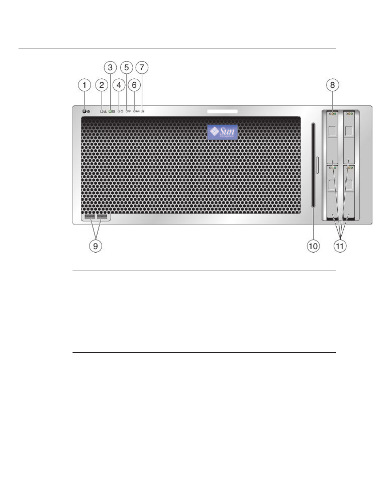
Figure Legend
1 Locate button/LED (white) 7 System overheat fault LED
2 Service action required LED
(amber)
8 Hard drive status LEDs
3 Power/OK LED (green) 9 USB ports (2)
4 Power button 10 DVD module
5 Top fan fault LED 11 Hard drives (4 maximum)
6 Rear power supply fault LED
Sun Fire X4600/X4600 M2 Server Back Panel Features and
Components
For front panel features and components, see “Sun Fire X4600/X4600 M2 Server Front Panel
Features and Components” on page 11
.
Sun Fire X4600/X4600 M2 Server Back Panel Featuresand Components
Sun Fire X4600 and Sun FireX4600 M2 Servers InstallationGuide • January 2010, Rev. A12
Page 13
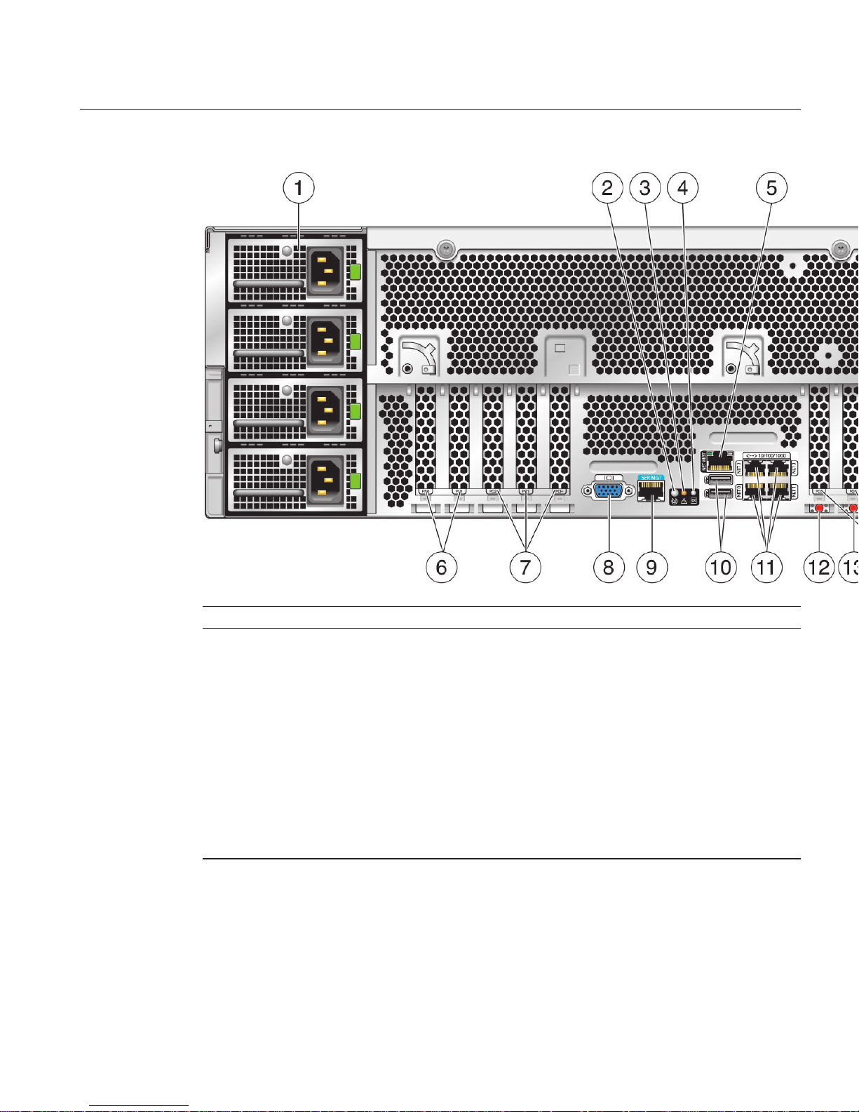
Figure Legend
1 Power supplies (4) 8 Video connector
2 Locate button/LED (white) 9 Serial management port
3 Service Action required LED
(amber)
10 USB ports (2 external, 1 internal on motherboard)
4 Power /OK LED (green) 11 10/100/1000 GigabitEthernet ports (4)
5 10/100 Ethernet port (for net
management)
12 NMI dump switch (SW3)
6 PCI-X card slots (2) 13 Reset switch (SW2)
7 PCIe card slots (3) 14 PCIe card slots (3)
Sun Fire X4600/X4600 M2 Server Back Panel Featuresand Components
13
Page 14

14
Page 15

Installing the Server Hardware
■
“Contents of the Box” on page 15
■
“Tools and Sta Required” on page 16
■
“Compatible Racks” on page 16
■
“Slide Rail Kit” on page 17
■
“How to Remove Components to Reduce Weight” on page 19
■
“How to Install the Express Slide Rails Onto the Server and the Rack” on page 19
■
“How to Insert the Server Into the Rack” on page 21
■
“How to Verify Slide-Rail Operation” on page 22
■
“Installing the Cable Management Arm (CMA)” on page 23
■
“How to Attach the Cable Management Arm (CMA)” on page 24
■
“How to Verify Cable Management Arm (CMA) Operation” on page 26
■
“How to Remove the Cable Management Arm (CMA)” on page 27
Contents of the Box
In addition to your server and power cords, you will nd the following items:
■
Installation Guide
■
Legal and Safety Documents
Note – The Installation Guide on http://docs.sun.com might be more up-to-date than the
printed manual in the server shipment.
■
DB9-RJ45 serial port adapter (530–3100) used to connect an Ethernet cable
■
Tools and Drivers CD/DVD. This CD/DVD includes BIOS, SP, and LSI rmware as well as
OS drivers. The current version is available at:
http://www.sun.com/servers/x64/x4600/
downloads.jsp
■
Sun Installation Assistant CD/DVD. Software application to update rmware (regardless of
OS) and to assist in installing Windows and Linux OSs.The current version is available at:
http://www.sun.com/servers/x64/x4600/downloads.jsp
■
SunVTS CD/DVD. Sun Validation Test Suite tests and validates Sun hardware by verifying
the conguration and functionality of hardware controllers, devices, and platforms. The
current version is available at:
http://www.sun.com/servers/x64/x4600/downloads.jsp
15
Page 16

Tools and Sta Required
Caution – The server weighs about 88 pounds (40 kg) when fully loaded with components. To
reduce the risk of serious personal injury or equipment damage, use a mechanical lift to install
the server into the rack. If a lift is not available, remove components as described in
“How to
Remove Components to Reduce Weight” on page 19
. This reduces the weight of the server to
35 pounds (16 kg).
Caution – Always load equipment into a rack from the bottom up so that it does not become
top-heavy and tip over. Deploy your rack’s anti-tilt bar to prevent the rack from tipping during
equipment installation.
Before installing the server into a rack, gather the tools, equipment, and sta required.
Tools,Equipment, and Stang Required Notes
Two trained sta Two people are needed to install the server and operate the lift.
#2 10–inch Phillips screwdriver
(magnetic tip recommended)
Optional. Required if you are hardmounting the server.
Mechanical lift Strongly recommended. If not available, reduce the weight of the server.
See
“How to Remove Components to Reduce Weight” on page 19.
Compatible rack See
“Compatible Racks” on page 16.
Slide rails Optional. See
“Slide Rail Kit” on page 17.
Cable management arm Optional. See
“Installing the Cable Management Arm (CMA)” on
page 23
.
Compatible Racks
The slide rails are compatible with a wide range of equipment racks that meet the following
standards:
■
Four-post rack (mounting at both front and rear).
Note – Two-post racks are not compatible.
■
Rack should have horizontal opening and unit vertical pitch conforming to ANSI/EIA
310-D-1992 or IEC 60927 standards.
Toolsand Sta Required
Sun Fire X4600 and Sun FireX4600 M2 Servers InstallationGuide • January 2010, Rev. A16
Page 17

■
Distance between front and rear mounting planes between approximately 26 to 34.5 inches
(660.4 mm and 876.3 mm).
■
Minimum clearance depth (to front cabinet door) in front of front rack mounting plane: 1
inch (25.4 mm).
■
Minimum clearance depth (to rear cabinet door) behind front rack mounting plane: 31.5
inches (800 mm) with cable management arm (recommended) or 27.5 inches (700 mm)
without the cable management arm.
■
Minimum clearance width (between structural supports and cable troughs) between front
and rear mounting planes: 18 inches (456 mm).
Note – The 4U Express Rail Rackmounting Kit (http://dlc.sun.com/pdf/820-4079/
820-4079.pdf)
card that is included with the slide rails and cable management assembly refers
to the rack as a retma (Radio Electronics Television Manufacturers Association) rack.
Slide Rail Kit
The slide rail kit that comes with your server is called the express slide rail or the tool-less slide
rail because it is simpler than older slide rails. It can be used with both square-hole and
round-hole racks. The cable management arm (CMA) might come in a separate box.
Slide Rail Kit
17
Page 18

Figure Legend
1 Slide rail (2) Attaches to rack post. The slide rail has an outer
rail and a middle section. The middle section
has the ball bearings which slide forward and
backward. Each end of the slide rail has an
attachment assembly.
2 Mountingbracket (2) Attaches to server. The mounting bracket is
also called the inner section because it is
inserted into the middle section of the slide rail.
3 (Optional) Cable management arm (CMA) Included only with Express Slide Rail and CMA
combination kit.
4 Shipping/hardmount hardware
Note – Ifyou want to secure the server for
shipping now or in the future, use the shipping
hardware. It is not possible to install the
shipping hardware after the slide rails are
installed. It is better to install the shipping
hardware during the slide rail installation.
The slide rail kit comes with the following shipping hardware:
Figure Legend
1 M6 screws (9) To secure server for shipping, install 8 screws, 2 per rack
post.
One extra screw is supplied.
2 Cage nuts Cage nuts are required for shipping server in square-hole
racks.
Slide Rail Kit
Sun Fire X4600 and Sun FireX4600 M2 Servers InstallationGuide • January 2010, Rev. A18
Page 19

▼
How to Remove Components to ReduceWeight
Caution – Circuit boards and hard drives contain electronic components that are extremely
sensitive to static electricity. Ordinary amounts of static electricity from clothing or the work
environment can destroy the components located on these devices. Do not touch the
components without antistatic precautions, especially along the connector edges. For more
information, see Antistatic Procedures and Cautions in the
Sun Fire X4600 and Sun Fire X4600
M2 Servers Service Manual
If a lift is not available, remove the followingcomponents to reduce weight:
■
All four power supplies
■
All four fan trays
■
All modules in the CPU bay (CPU modules and ller modules)
This reduces the weight of the server to about 35 pounds (16 kg).
Removing and Installing Components
Sun Fire X4600 and Sun Fire X4600 M2 Servers Service
Manual
▼
How to Install the Express Slide Rails Onto the Server and the Rack
Installing the slide rails and cable management arm for the rst time takes approximately 45 to
60 minutes.
Note – The express slide rail kit comes with the 4U Express Rail Rackmounting Kit
(http://dlc.sun.com/pdf/820-4079/820-4079.pdf)
card that contains illustrations that you
should refer to during this procedure. It can also be used to block out the 4 unit (4U) space to be
occupied by the server.
Attach the mounting bracketsto the server.
Cach mounting bracket has a at side, which ts against the server chassis. The other side has a
pair of rims that t into the slide rails. Each bracket has 6 key-shaped holes which t over the
pins on the side of the server.
Note – The last (rear-most) hole is not used.
a. Position a bracketso that the green lock leversare at the front of the server and theholes on
the bracket areover the pins on the server.
b. Hang the bracket on the pins.
The middle of the bracket will bow out slightly so that the middle hole does not engage.
BeforeYouBegin
●
See Also
1
Slide Rail Kit
19
Page 20

c. Press down on the center of the bracket and slide forward.
All 5 pins should lock into place with an audible click.
d. Repeat the abovesteps with the other bracket.
Use the installationcard to determine the 4U space thatwill be occupied by the server.
The slide rails cover the holes on the 2U space on the bottom of the 4U space that is occupied by
the server.
The installation card is designed so that it exactly covers a 4U space in the rack. The lower half
of the card is narrower than the rest, so that the holes used by the slide rails are visible.
(Optional for securing the server and slide railsfor shipping) If you plan to ship the server and
slide rails in placeand you have a rack withsquare holes, place cage nuts in the holesat the top
and the bottom of the 2U slide rail space. It is not possibleto install the cage nuts after the slide
rail is installed.
Tip – Installthe cage nuts if you plan to ship the server in the future.
From behind the rack post, put the bottom tab of the cage nut into the hole and squeeze the top
tab into the hole.
Note – In normal installation, securing is not required. Securing provides extra stability in
special circumstances, such as shipping the server in place, that is, shipping the server mounted
in the rack and then shipping the rack.
Attach the slide railsto the rack.
Each slide rail has an attachment assembly at either end. Each assembly has two pins that t into
the rack holes (either round and square) and a spring that holds the rack rail against the
assembly. The front part of the rail is stamped with the word “FRONT.” The rear part of the rail
is stamped with the word “REAR.”
a. Orient the slide rail with the ball bearing track at the front ofthe rack.
b. Extend the slide rail tothe length of the rack.
c. Slide the front attachmentassembly over the rack’s posts, so that the pinst into the rack
holes. Push theassembly into the rack post until it clicks intoplace.
d. Insert the rear attachment assembly intothe holes of the rack post.
2
3
4
Slide Rail Kit
Sun Fire X4600 and Sun FireX4600 M2 Servers InstallationGuide • January 2010, Rev. A20
Page 21
Tip – Press the gray plastic tabs toward the rack post to adjust the length of the slide rails.
e. Repeat the above steps with the other slide rail.
“How to Insert the Server Into the Rack” on page 21
▼
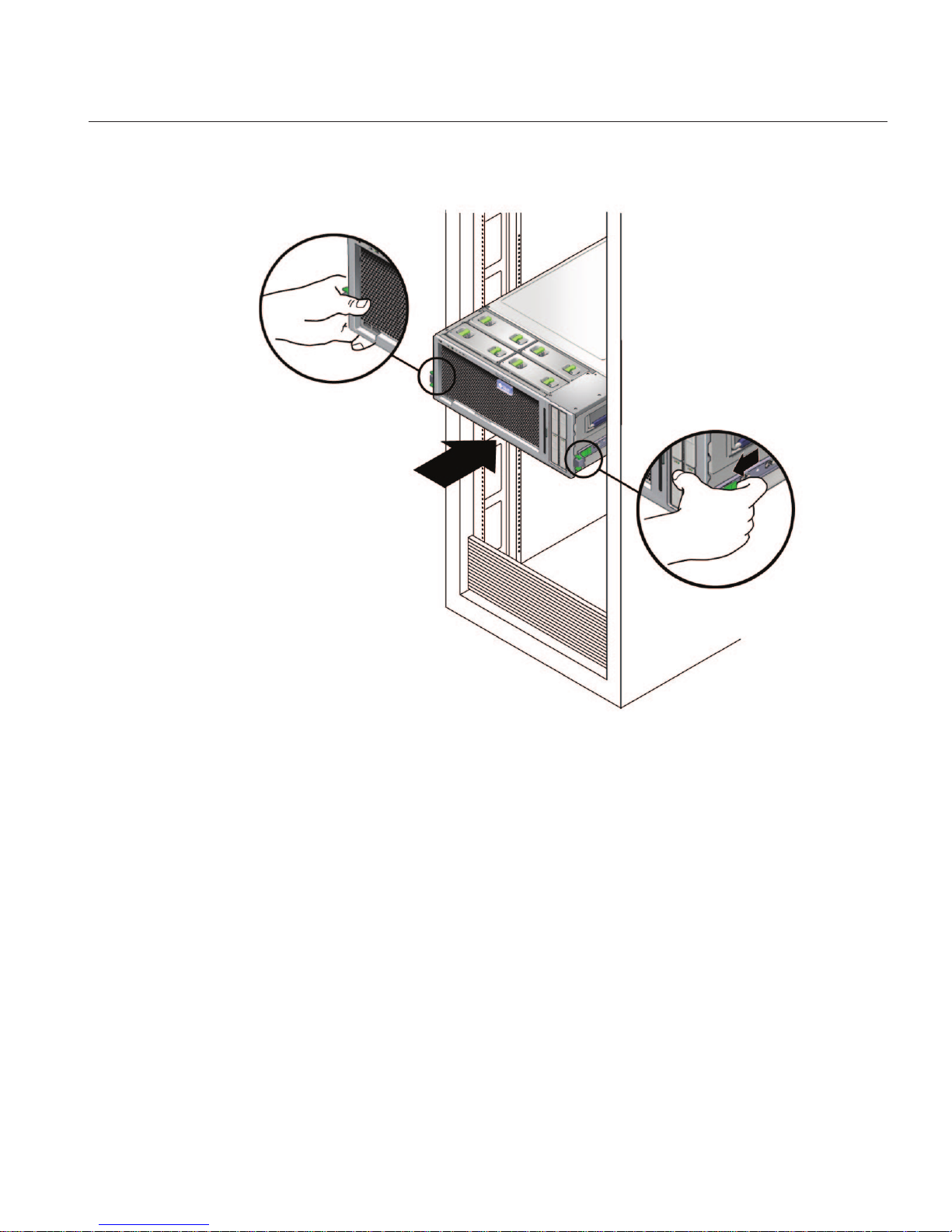
How to Insert the Server Into the Rack
The following procedure explains how to insert the server, with the mounting brackets
attached, into the slide-rail assembly on the rack.
Caution – To reduce the risk of serious personal injury or equipment damage, use a mechanical
lift to install the server into the rack. If a lift is not available, remove components as instructed
in
“How to Remove Components to Reduce Weight” on page 19.
Perform the steps in “How to Install the Express Slide Rails Onto the Server and the Rack” on
page 19
.
Pull the middle sections fromthe outer rails so that the middle sections areextended until they
click and lock into place.
(Two trainedsta) Lift the server by the handles and insert the mounting bracketsattached to
the server into the middle sections untilthe brackets engage with the middle sections.
Note – Make sure that the mounting brackets enter the middle sections, straight on and not at an
angle and that the ball bearing retainer is engaged with the inner sections.
Push the server into therack until the slide rails lock into place.
At this point the server is engaged with the slide rails but is not pushed into the rack fully.
To release the lock on themounting brackets, locate the green plasticrelease tabs (on both left
and right sides) on themounting bracket.
Next Steps
BeforeYouBegin
1
2
3
4
Slide Rail Kit
21
Page 22
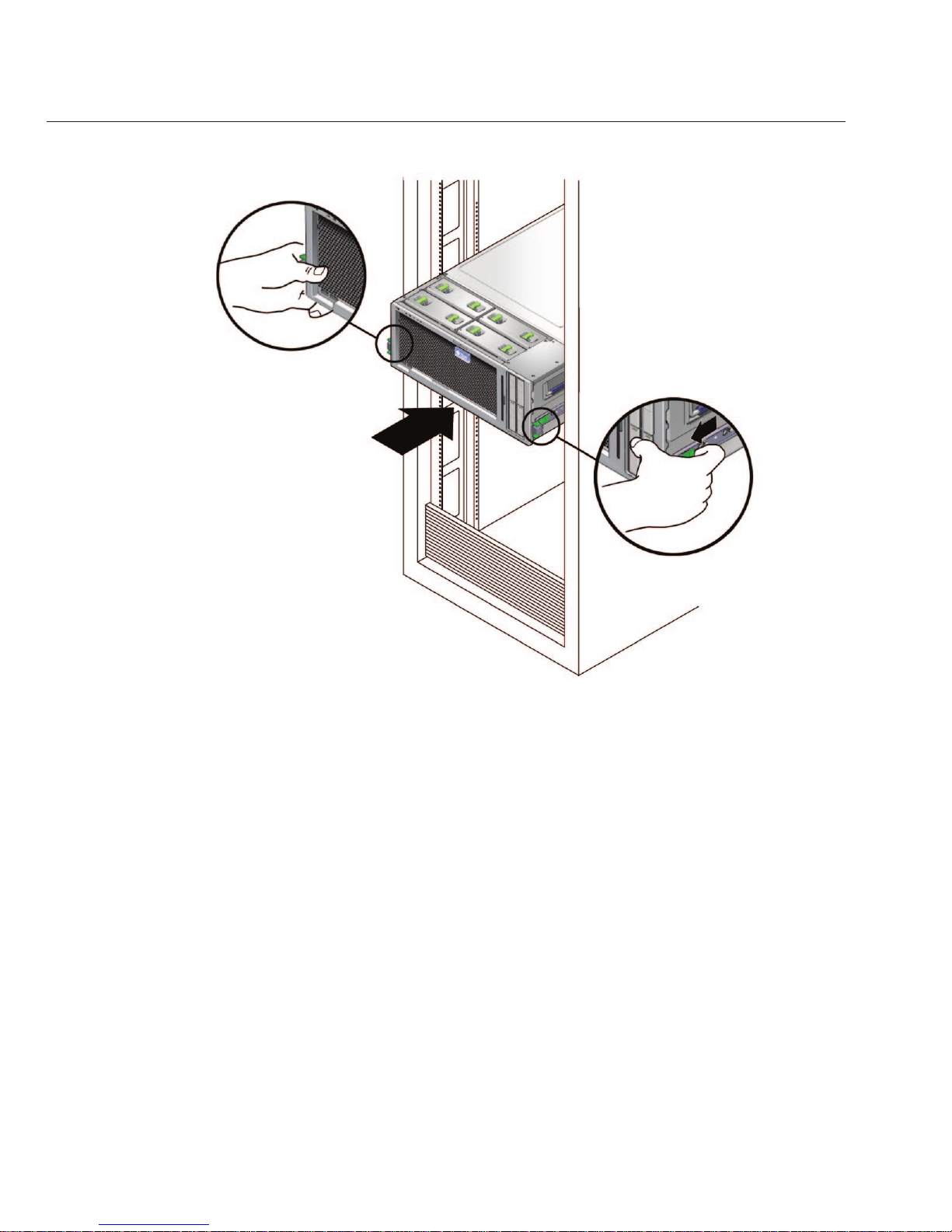
With two hands, slide the green plastic tabs towardyou to release the lock and pushthe server
all the way intothe rack.
“How to Verify Slide-Rail Operation” on page 22
“Removing the Server From the Rack” on page 29
▼
How to Verify Slide-Rail Operation
Perform the steps in “How to Insert the Server Into the Rack” on page 21.
To pull the server out of the rack,squeeze the front green lock levers andpull the server out of
the rack until the slide rails reach their stops.
Push the server back intothe rack until it reaches the internal stops.
To release the lock on themounting brackets, locate the green plasticrelease tabs (on both left
and right sides) on themounting bracket.
5
Next Steps
See Also
BeforeYouBegin
1
2
3
Slide Rail Kit
Sun Fire X4600 and Sun FireX4600 M2 Servers InstallationGuide • January 2010, Rev. A22
Page 23
With two hands, slide the green plastic tabs towardyou to release the lock and pushthe server
all the way intothe rack.
“Installing the Cable Management Arm (CMA)” on page 23
Installing the Cable Management Arm (CMA)
The cable management arm is not required, but highly recommended to protect the I/O and
power cables from damage. The CMA kit includes the following:
■
Installation card
■
CMA
■
CMA extension
4
Next Steps
Installing theCable Management Arm (CMA)
23
Page 24
Caution – You can damage the I/O and power cables if you slide the system from the rack
without rst running all cables at the rear through the CMA.
This section has the following procedures.
■
“How to Attach the Cable Management Arm (CMA)” on page 24
■
“How to Verify Cable Management Arm (CMA) Operation” on page 26
■
“How to Remove the Cable Management Arm (CMA)” on page 27
▼
How to Attach the Cable Management Arm (CMA)
Note – Do not run cables from another server through the CMA. Use one CMA per server.
The CMA comes with the 4U Express Rail Rackmounting Kit (http://dlc.sun.com/pdf/
820-4079/820-4079.pdf)
card that contains illustrations that you should refer to during this
procedure.
This procedure assumes that you have installed the server into the rack. See
“How to Insert the
Server Into the Rack” on page 21
.
If necessary,slide the server back until it is fully inside the rack.
Unpack the CMA parts and take them to the rear of the equipment rack.
Note – References to “left” or “right” in this procedure assume that you are facing the rear of the
equipment rack.
BeforeYouBegin
1
2
Installing theCable Management Arm (CMA)
Sun Fire X4600 and Sun FireX4600 M2 Servers InstallationGuide • January 2010, Rev. A24
Page 25
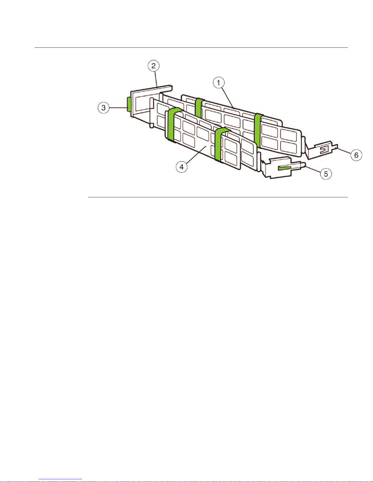
Figure Legend
1 Cable Management Arm (CMA)
2 Support latch with CMA extension installed. Note that CMA extension is a detachable
piece.
3 Power supply access tab (press and rotate CMA for access to power supplies.)
4 Hook and loop straps
5 Outer latch with green insert
6 Inner latch
Attach the CMA extensionto the left slide rail.
Push on the extension's metal clip (labeled PUSH) as you slide the extension into the left slide
rail.
3
Installing theCable Management Arm (CMA)
25
Page 26

Insert the right inner latch (numbered6 in the CMA illustration) into the rightrear slide rail. The
inner latch does nothave the green insert.
Note – Insert the inner latch into the mounting bracket part of the slide rail, which extends about
5 inches (approximately 12.5 centimeters) from the server itself.
Insert the right outer latch (numbered 5 in the CMA illustration) into themiddle part of the slide
rail.The right outer latch has the greeninsert.
Attach the light gray support latch (numbered 2 in the CMAillustration) into the CMA extension
on the left slide rail.
Install cables to yourserver, using the hook and loop straps,and route the cables through the
CMA.
“How to Verify Cable Management Arm (CMA) Operation” on page 26
▼
How to Verify Cable Management Arm (CMA)Operation
Perform the steps in “How to Attach the Cable Management Arm (CMA)” on page 24.
Inspect the attached cables forany binding or kinks.
Verify thatthe CMA extends and does not bind in theslide rails.
4
5
6
7
Next Steps
BeforeYouBegin
1
2
Installing theCable Management Arm (CMA)
Sun Fire X4600 and Sun FireX4600 M2 Servers InstallationGuide • January 2010, Rev. A26
Page 27

Make sure thatthe power cord cables are securedto the chassis with the clips on each power
supply.
Adjust the cables andCMA as required, and then retestthe operation of the slide rails and CMA.
Tip – To maximize airow, tie-wrap the power cords at the bottom of the CMA troughs and the
data cables at the top of these troughs.
▼
How to Remove the Cable Management Arm (CMA)
Unplug any powercables and data cables from the server.
Remove the support latchfrom the CMA extension.
Remove the rightinner latch.
This exposes the right outer latch.
Press on thegray tab (labeled Push) on the right outerlatch to release the right outer latch.
Remove the CMAextension from the left rear of the rack rail.
Remove the CMAfrom the slide rail.
“How to Remove the Server From the Rack” on page 29
3
4
1
2
3
4
5
6
See Also
Installing theCable Management Arm (CMA)
27
Page 28

28
Page 29

Removing the Server From the Rack
This procedure assumes that you have turned o the server, removed the cable management
arm, and removed any cables or cords that would restrict the movement of the server.
See the
4U Express Rail Rackmounting Kit (http://dlc.sun.com/pdf/820-4079/
820-4079.pdf)
card for illustrations that you should refer to during this procedure. This card is
shipped with the slide rail and the cable management arm.
■
“How to Remove the Server From the Rack” on page 29
▼
How to Remove the Server From the Rack
Caution – Tip hazard. If available, extend the anti-tilt legs on the rack before you extend the
server.
Caution – The Sun Fire X4600/X4600 M2 server weighs about 85 pounds (40 kg) when fully
loaded with components. To reduce the risk of serious personal injury or equipment damage,
use a mechanical lift to remove the sever from the rack.
From the front of the rack, squeeze the slide-rail locks (with green plastic handles) to release the
lock and completely extend the server from therack.
If a lift is not available, remove components to reduce the system’s weight. See
“How to Remove
Components to ReduceWeight”on page 19
.
Using two hands,slide the gray plastic tabs on the mounting brackets attached to the server
toward yourself to releasethe server from theslide rail.
BeforeYouBegin
1
2
3
29
Page 30

Caution – At this point, the server is now free from the rail, and you need to support the weight of
the server by holding the handles.
Note – If you do not have the server completely extended from the rack, you cannot access the
gray tabs.
(Two trainedsta) Carefully remove the server fromthe rack.
To return the middle section of the sliderail back into the rack:
a. Push the graymetal tab on the middle section of one slide rail andthen slide the rail middle
section back into the rack.
4
5
Removing theServer From the Rack
Sun Fire X4600 and Sun FireX4600 M2 Servers InstallationGuide • January 2010, Rev. A30
Page 31

b. Repeat for the other slide rail.
Remove the sliderails from the rack by doing the following.
a. To release the front assembly, push the upper and lower gray plastic tabs on theslide rail
attachment assembly towardthe rack post.
b. Support the weight of the sliderails as you pull the slide rails outwardand away from the
rack posts.
c. Repeat for the rear attachment.
d. Repeat for the otherslide rail.
To remove both mountingbrackets from the server,gently lift the metal clip over the pin and
then slide the mounting brackettoward the rear of theserver.
6
7
Removing theServer From the Rack
31
Page 32

“How to Insert the Server Into the Rack” on page 21See Also
Removing theServer From the Rack
Sun Fire X4600 and Sun FireX4600 M2 Servers InstallationGuide • January 2010, Rev. A32
Page 33

Cabling and Power
■
“Cabling Diagram” on page 33
■
“How to Cable the Server” on page 34
■
“How to Apply Standby Power for Initial Service Processor Conguration” on page 35
■
“How to Power On All Server Components” on page 36
■
“How to Power O the Server” on page 37
Cabling Diagram
33
Page 34
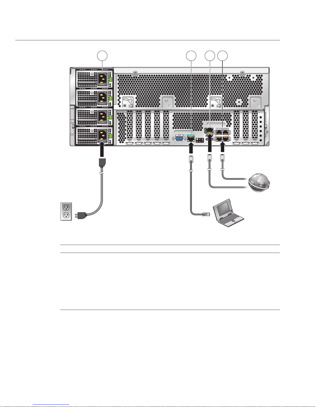
TABLE 1 Cabling Diagram
Figure Legend
1 Connect power cable to power source.
2 Connect a serial cable between the SER MGT port and a terminal device or a PC.
Note – You might need an adapter. The server comes with a DB9–to-RJ45 serial port adapter.
3 (Optional) Connect an Ethernet cable between the NET MGT port and the network to which
future connections to the SP and the host will be made.
4 Connect an Ethernet cable between one of the NET ports and the network.
▼
How to Cable the Server
For details on the front and back panels of the server, see “Sun Fire X4600/X4600 M2 Server
Front and Back Panel Features and Components” on page 11
.
1 2
3
4
Cabling Diagram
Sun Fire X4600 and Sun FireX4600 M2 Servers InstallationGuide • January 2010, Rev. A34
Page 35

Connect network cables toone or more of the 10/100/1000 Gigabit Ethernet connectors labeled
NET 0, NET 1, NET 2, andNET 3 (labeled 4 inthe illustration).
If you plan tointeract with the system console directly, connect a mouse and a keyboardto the
USB connectors and a monitorto the video connector.
This step is optional, unless your operating system does not support headless operation.
Note – The system console is permanently congured to a resolution of 1024 x 768 and a color
depth of 24 bits. This conguration cannot be changed. This limitation is necessary to support
video redirection by the Integrated Lights Out Manager (ILOM).
If you plan toaccess the ILOM overthe network, connect a network cable to the10/100 Ethernet
connector labeled NET MGT.
This step is necessary to use the full range of ILOM functionality.
If you plan toaccess the ILOM command-lineinterface using the serial management port,
connect a compatible cable to the RJ45 connector labeled SER MGT.
An adapter is shipped with the system, part number 530-3100. This a DB9-to-RJ45 adapter.
This adapter is also used with other Sun Fire systems and with Sun Netra systems. It is
compatible with the CISCO 72-3383-01 console cable.
“Communicating With the ILOM and the System Console” on page 45
▼
How to Apply Standby Power forInitial Service ProcessorConguration
Use this procedure to apply standby power to the SP before initial conguration.
Caution – Possible equipment damage. Do not operate the server without all fans, component
heatsinks, air baes, and the cover installed. Severe damage to server components can occur if
operated without adequate cooling mechanisms.
Caution – A maximum of two power cords can be connected to a single branch circuit. The
remaining power cord(s) must be connected to a second branch circuit.
1
2
3
4
See Also
Cabling Diagram
35
Page 36

Ensure that groundedAC power cords areplugged into the four AC powerconnectors on the
back panel of theserver and into groundedAC power outlets ontwo separatebranch circuits (see
Caution above).
When power is connected, the server boots into standby power mode. After the SP boots and is
ready to use, the Power/OK LED on the front panel ashes to indicate standby power mode. For
the LED location, see
“Sun Fire X4600/X4600 M2 Server Front Panel Features and
Components” on page 11
.
Note – Do not apply main power to the rest of the server until you are ready to install or
congure a platform operating system. At this point, standby power is supplied only to the
Graphics Redirect and Service Processor (GRASP or SP for short) board and power supply fans.
To begin the initial SP conguration, see “Communicating With the ILOM and the System
Console” on page 45
Controlling Power and Performing Hardware Reset Sun Fire X4600 and X4600 M2 Server
Service Manual (http://dlc.sun.com/pdf/819-4342-16/819-4342-16.pdf)
▼
How to Power On All Server Components
This procedure powers on all server components and is dierent from applying standby power,
which powers on the service processor only.
Verify that power cords havebeen connected and that standby power is on.
In standby power mode, the Power/OK LED on the front panel blinks.
Use a pointed object topress and release the recessed Power button on the server front panel.
When main power is applied to the full server, the Power/OK LED next to the Power button
remains lit and no longer blinks.
●
Next Steps
See Also
1
2
Cabling Diagram
Sun Fire X4600 and Sun FireX4600 M2 Servers InstallationGuide • January 2010, Rev. A36
Page 37
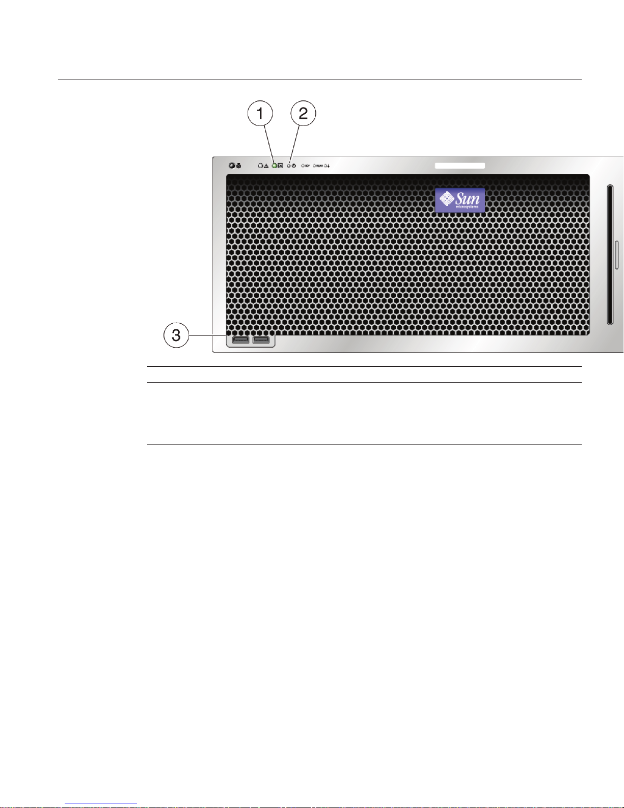
Figure Legend
1 Power/OK LED
2 Power button
3 USB connectors
To begin the initial SP conguration, see “Communicating With the ILOM and the System
Console” on page 45
Controlling Power and Performing Hardware Reset Sun Fire X4600 and X4600 M2 Server
Service Manual (http://dlc.sun.com/pdf/819-4342-16/819-4342-16.pdf)
▼
How to Power O the Server
To power o the server frommain power mode, use one ofthe following two methods:
■
Graceful shutdown: Use a pointed nonconducting object to press and release the Power
button on the front panel. This causes Advanced Conguration and Power Interface (ACPI)
enabled operating systems to perform an orderly shutdown of the operating system. Servers
not running ACPI-enabled operating systems will shut down to standby power mode
immediately.
Next Steps
See Also
●
Cabling Diagram
37
Page 38
Caution – For servers not running ACPI-enabled OSs, there is a possible data loss. This is the
same as an emergency shutdown.
■
Emergency shutdown: Press and hold the Power button for four seconds to force the main
power o and enter standby power mode.
When main power is o, the Power/OK LED on the front panel blinks, indicating that the
server is in standby power mode.
Note – To completely power o the server, you must disconnect the AC power cords from
the back panel of the server.
■
“How to Apply Standby Power for Initial Service Processor Conguration” on page 35
■
“How to Power On All Server Components” on page 36
■
Sun Fire X4600 and X4600 M2 Server Service Manual (http://dlc.sun.com/pdf/
819-4342-16/819-4342-16.pdf)
See Also
Cabling Diagram
Sun Fire X4600 and Sun FireX4600 M2 Servers InstallationGuide • January 2010, Rev. A38
Page 39

Getting Service for Your Server
To get service for your server, nd your server's serial number, and contact Sun service through
the following web site:
http://www.sun.com/support
■
“How to Find the Server's Serial Number” on page 39
▼
How to Find the Server's Serial Number
You might need to have the serial number of your server to ask for service on your system. Keep
this number handy for future use.
Find the serialnumber, using one of theseways:
■
On the front panelof the server, look at the bottom ledge (near the center) to nd the
server's serial number.
■
Find the yellowCustomer Information Sheet (CIS)attached to your server packaging.This
sheet includes the serial number.
■
From ILOM,enter the show /SYS command or go to the System Information tab in the ILOM
browser interface.
For an illustration of the front panel of the server, see
“Sun Fire X4600/X4600 M2 Server Front
Panel Features and Components” on page 11.
●
See Also
39
Page 40

40
Page 41
Sun Fire X4600/X4600 M2 Server Server
Specications
■
“Physical Specications For the Sun Fire X4600/X4600 M2 Server” on page 41
■
“Power Specications For the Sun Fire X4600/X4600 M2 Server” on page 41
■
“Environmental Specications” on page 42
■
“Acoustic Specications” on page 42
Physical Specications For the Sun Fire X4600/X4600 M2
Server
This section contains specications for the Sun Fire X4600/X4600 M2 Server.
Specication Value
Width 17.5 inches (445 mm)
Height 6.9 inches (176 mm)
Depth With bezel: 24.75 inches (629 mm)
With bezel and rear power supply latches: 25.25
inches (642 mm)
Weight Maximum standalone server: 88 pounds (40 kg)
Maximum with rack-mount kit and cable
management arm assembly: 106 pounds (48 kg)
Power Specications For the Sun Fire X4600/X4600 M2 Server
Specication Value
Universal AC input 100 – 240 VAC 50/60 Hz
Maximum input current at 200 VAC 10 A
Maximum input current at 100 VAC 20 A
41
Page 42

Specication Value
Maximum power available 1975 W
Maximum power consumed 1715 W
Environmental Specications
Specication Value
Temperature (operating) 41° - 90° F (5 ° - 32.2° C)
Temperature (storage) -40° - 149° F
Humidity 20% - 90% non-condensing
Operating altitude 0 - 10,000 feet (0 - 3048 m) maximum
Decrease operating temperature 1.8°F(1°C)per985
feet (300 m) above 2955 feet (900 m) altitude
Airow Airow typical (for room temperatures 73° F and
below (23 °C and below): 200 CFM
Airow max possible: 400 CFM.
Acoustic Specications
Specication Value
L
WAd
(sound power):
at or below 25C 8.2 dB
above 25C 9.0 dB
L
pAm
(average bystander sound pressure):
at or below 25C 67 dB
above 25C 75 dB
Environmental Specications
Sun Fire X4600 and Sun FireX4600 M2 Servers InstallationGuide • January 2010, Rev. A42
Page 43

ManagingYour Server
You have several dierent options for managing your server depending on your situation.
■
Managing many servers
Your server can be managed with a wide variety of system management tools, created both
by Sun and by third parties. For more information on the system management tools, see the
Sun Tools information at:
http://www.sun.com/systemmanagement/managementtools.jsp
Here is a sampling of some of these tools:
■
If your server is one of many Sun x64 and SPARC servers that you want to manage from
a single interface, you can use the Sun xVM Ops Center. For more details, see:
http://www.sun.com/software/products/opscenter
■
If you already have third-party system management tools, Sun servers can integrate with
many third-party tools. For more details, see:
http://www.sun.com/systemmanagement/tools.jsp
■
Managing a single server
■
Sun Installation Assistant (SIA) is an application that you can use for initial server
conguration. SIA helps you to update rmware (ILOM rmware, BIOS, and RAID
controller software) and to automate installation of Linux and Windows operating
systems. For more details, see
Sun Installation Assistant 2.2 User’s Guide for the Sun Fire
X4600/X4600 M2 Server.
■
The Integrated Lights Out Manager (ILOM) is built-in software and hardware that you
can use to monitor the status and conguration of your server. For more information,
see the following section:
“Overview of ILOM Software” on page 44
43
Page 44

Overview of ILOM Software
Sun's Integrated Lights Out Manager (ILOM) provides advanced service processor hardware
and software that you can use to manage and monitor your Sun servers. ILOM's dedicated
hardware and software is preinstalled on a variety of Sun server platforms, including x64-based
Sun Fire servers, Sun Blade modular chassis systems, Sun Blade server modules, as well as on
SPARC-based servers. ILOM is a vital management tool in the data center and can be used to
integrate with other data center management tools already installed on your systems.
Sun is currently transitioning many systems to support ILOM so that customers will have a
single, consistent, and standards-based service processor (SP) across Sun's product lines. For
customers, this means you have:
■
A single, consistent system management interfaces for operators
■
Rich protocol and standards support
■
Third-party management support
■
System management functions integrated into Sun servers at no extra cost
ILOM enables you to actively manage and monitor the server independently of the operating
system state, providing you with a reliable Lights Out Management (LOM) system. With ILOM,
you can proactively:
■
Learn about hardware errors and faults as they occur
■
Remotely control the power state of your server
■
View the graphical and non-graphical consoles for the host
■
View the current status of sensors and indicators on the system
■
Determine the hardware conguration of your system
■
Receive generated alerts about system events in advance via IPMI PETs, SNMP traps, or
email Alerts
The ILOM service processor (SP) runs its own embedded operating system and has a dedicated
Ethernet port, which together provide out-of-band management capability. In addition, you
can access ILOM from the server's host operating system. Using ILOM, you can remotely
manage your server as if you were using a locally attached keyboard, monitor, and mouse.
ILOM automatically initializes as soon as power is applied to your server. It provides a
full-featured, browser-based web interface and has an equivalent command-line interface
(CLI). There is also an industry-standard SNMP interface and IPMI interface.
Overview of ILOM Software
Sun Fire X4600 and Sun FireX4600 M2 Servers InstallationGuide • January 2010, Rev. A44
Page 45

CommunicatingWith the ILOM and the System
Console
These topics provide instructions for connecting to the system service processor (SP) Integrated
Lights Out Manager (ILOM) and the system console.
■
“Server Connections” on page 45
■
“Determining the SP IP Address” on page 47
■
“Connecting to the ILOM” on page 49
■
“Connecting to the System Console” on page 52
Server Connections
The following illustration shows the cabling locations on the rear panel of the server.
45
Page 46

TABLE 2 Cabling Diagram
Figure Legend
1 Connect power cable to power source.
2 Connect a serial cable between the SER MGT port and a terminal device or a PC.
Note – You might need an adapter. The server comes with a DB9–to-RJ45 serial port adapter.
3 (Optional) Connect an Ethernet cable between the NET MGT port and the network to which
future connections to the SP and the host will be made.
4 Connect an Ethernet cable between one of the NET ports and the network.
1 2
3
4
Server Connections
Sun Fire X4600 and Sun FireX4600 M2 Servers InstallationGuide • January 2010, Rev. A46
Page 47

About ILOM SP IP Addresses and the ILOM Interfaces
The ILOM SP is assigned a DHCP IP address by default. There are two requirements for DHCP
IP address assignment to occur:
■
Connection to your network must be through a NET MGT port.
■
DHCP services must be present on your network infrastructure.
If a DHCP server cannot be reached after three DHCP requests, the ILOM SP is assigned a static
IP address based on the network management port MAC address. This IP address is always in
the format 192.168.xxx.xxx.
You can choose from one of several ILOM SP interfaces to support system management on
your server. You can access SP rmware applications through the following ILOM SP
interfaces:
■
Serial port command-line interface (CLI) (local access)
■
Secure shell (SSH) CLI (remote access over the network)
■
Web browser user interface (BUI) (remote access over the network)
Determining the SP IP Address
You need to determine the service processor (SP) IP (network) address to use the SP Integrated
Lights Out Manager (ILOM) to manage the server. You can determine the IP address through
either one of these ways:
■
“How to Get the SP IP Address By Using the BIOS Setup Utility” on page 47
■
“How to Get the SP IP Address By Using a Serial Connection and the CLI” on page 48
▼
How to Get the SP IP Address By Using the BIOS Setup Utility
■
Complete the hardware setup as described in the hardware setup documentation.
■
Apply standby power for your server by plugging an AC cord into the system power supply.
See
“Server Connections” on page 45 for the location of the power cord connectors.
Reboot the server.
Press the F2key when prompted for the BIOS Setup Utility.
In the BIOS Setup Utility, choose Advanced → IPMI 2.0 Conguration → Set LAN Conguration
→ IP address.
The IP address for the SP is displayed.
BeforeYouBegin
1
2
3
Determining theSP IP Address
47
Page 48

▼
How to Get the SP IP Address By Using a Serial Connection and the CLI
■
Complete the hardware setup as described in the hardware setup documentation.
■
Apply standby power for your server by plugging an AC cord into the system power supply.
See
“Server Connections” on page 45 for the location of the power cord connectors.
Verify that your terminal, laptop,or terminal server is operational.
Congure the terminaldevice or the terminal emulation software running ona laptop or PC to
the following settings:
■
8N1: eight data bits, no parity, one stop bit
■
9600 baud
■
Disable hardware ow control (CTS/RTS)
■
Disable software ow control (XON/XOFF)
Connect a serial cable fromthe RJ-45 SERIAL MGT port on the server’sback panel to a terminal
device.
See
“Server Connections” on page 45 for the location of the RJ-45 SERIAL MGT port.
Press Enter onthe terminal device to establish a connection between thatterminal device and
the ILOMSP.
The SP eventually displays a login prompt, such as the following example:
SUNSP0003BA84D777 login:
In this example login prompt:
■
The string SUNSP is the same for all SPs.
■
0003BA84D777is the product serial number by default. This value can also be the host name,
which is assigned by user or DHCP server.
Log in tothe ILOM.
a. Typethe default user name: root.
b. Typethe default password: changeme.
Once you have successfully logged in, the SP displays its default command prompt:
->
You can now run CLI commands to congure ILOM for the server’s user accounts, network
settings, access lists, alerts, and so on. For detailed instructions on CLI commands, see the
Sun Integrated Lights-Out Manager 3.0 CLI Procedures Guide.
BeforeYouBegin
1
2
3
4
5
Determining theSP IP Address
Sun Fire X4600 and Sun FireX4600 M2 Servers InstallationGuide • January 2010, Rev. A48
Page 49

To display the SP IP address, type:
cd /SP/network
Note – You can switch back to the SP CLI from the serial console by entering the Esc ( key
sequence.
Connecting to the ILOM
This section describes three dierent procedures for connecting to the ILOM:
■
“How to Connect to the Command-Line Interface Using SSH” on page 49
■
“How to Connect to the ILOM Command-Line Interface Through the Serial Management
Port” on page 49
■
“How to Connect to the ILOM Web Interface” on page 51
▼
How to Connect to the Command-Line Interface Using SSH
■
Perform the hardware setup as described in the hardware setup documentation.
■
Apply standby power to the server by connecting AC power to the system power supply. See
“Server Connections” on page 45 for the location of the power connectors.
Connect the server to the internetwith an Ethernet cable connected to the server's RJ-45 NET
MGT Ethernet port.
See
“Server Connections” on page 45 for the location of the RJ-45 NET MGT port.
Using a client system,access a command line and establish aSecure Shell (SSH) connection to
the service processor’s IP address with the following command:
ssh -l root sp_ip_address
For example, to connect to the SP with the DHCP-assigned IP address of 129.144.82.20, type the
following command:
ssh -l root 129.144.82.20
Log in tothe ILOM.
The default user name is root and the default password is changeme.
▼
How to Connect to the ILOM Command-Line Interface Through the
Serial Management Port
Use this procedure to establish a serial connection to the ILOM SP so that you can perform
initial conguration of ILOM.
■
Perform the hardware setup as described in the hardware setup documentation.
6
BeforeYouBegin
1
2
3
BeforeYouBegin
Connecting tothe ILOM
49
Page 50

■
Apply standby power to the server by connecting AC power to the system power supply. See
“Server Connections” on page 45 for the location of the power connectors.
■
Verify that your terminal, laptop, or terminal server is operational.
Congure the terminaldevice or the terminal emulation software running ona laptop or PC to
the following settings:
■
8N1: eight data bits, no parity, one stop bit
■
9600 baud
■
Disable hardware ow control (CTS/RTS)
■
Disable software ow control (XON/XOFF)
Connect a serial cable fromthe RJ-45 SERIAL MGT port on the server’sback panel to a terminal
device.
See
“Server Connections” on page 45 for the location of the RJ-45 SERIAL MGT port.
Press Enter onthe terminal device to establish a connection between thatterminal device and
the ILOMSP.
The SP eventually displays a login prompt, such as the following example:
SUNSP0003BA84D777 login:
In this example login prompt:
■
The string SUNSP is the same for all SPs.
■
0003BA84D777is the product serial number by default. This value can also be the host name,
which is assigned by user or DHCP server.
Log in tothe ILOM.
a. Typethe default user name: root.
b. Typethe default password: changeme.
Once you have successfully logged in, the SP displays its default command prompt:
->
You can now run CLI commands to congure ILOM for the server’s user accounts, network
settings, access lists, alerts, and so on. For detailed instructions on CLI commands, see the
Sun Integrated Lights-Out Manager 3.0 CLI Procedures Guide.
To start the serial console, type:
cd /SP/console
->start
1
2
3
4
5
Connecting tothe ILOM
Sun Fire X4600 and Sun FireX4600 M2 Servers InstallationGuide • January 2010, Rev. A50
Page 51
Note – You can switch back to the SP CLI from the serial console by entering the Esc ( key
sequence.
▼
How to Connect to the ILOM Web Interface
■
Perform the hardware setup as described in the hardware setup documentation.
■
Apply standby power to the server by connecting AC power to the system power supply. See
“Server Connections” on page 45 for the location of the power connectors.
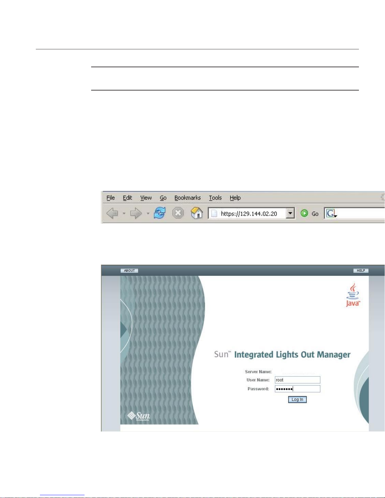
Typethe IP address of the ILOMSP in the browser locator boxand press Enter.For example, if the
IP address foryour ILOM SP is 129.144.02.20, youwould enter it as shown:
Log in to theweb interface using the default user name, root, and thedefault password,
changeme.
BeforeYouBegin
1
2
Connecting tothe ILOM
51
Page 52

Connecting to the System Console
There are three dierent ways to connect to the system console.
■
Physical console. See “How to Connect to the Server Locally (Physical Console)” on page 52
■
Remote console through the ILOM web interface. See “How to Connect Remotely Using the
ILOM Web Interface” on page 52
■
Serial console through the ILOM command-line interface. See “How to Connect to the
Serial Console Using the ILOM Command-Line Interface” on page 57
▼
How to Connect to the Server Locally (Physical Console)
If you plan to interact with the system console directly, make the connections described in this
procedure. See
“Server Connections” on page 45 the for the locations of the system connectors.
Perform the hardware setup as described in the hardware setup documentation.
Connect a mouse and akeyboard to the server USB connectors.
Connect a monitor tothe server video connector.
For the locations of the USB connectors and the server video connector, see
“Sun Fire
X4600/X4600 M2 Server Front and Back Panel Features and Components” on page 11
.
▼
How to Connect Remotely Using the ILOM Web Interface
The requirements for the JavaRConsole (remote console) system are:
■
Solaris, Linux, or Windows operating system is installed.
■
The system must be connected to a network that has access to the server's Ethernet
management port.
■
Java Runtime Environment (JRE) 1.5 or later is installed.
■
If the remote console system is running Solaris OS, volume management must be disabled
for the remote console to access the physical oppy and CD/DVD-ROM drives.
■
If the remote console system is running Windows, Internet Explorer Enhanced Security
must be disabled.
■
The remote console system and ILOM service processor are set up according to the
instructions in the Sun Integrated Lights Out Manager (ILOM) 3.0 Web Interface Procedures
Guide.
Start the remote console applicationby typing the IP address of the ILOM service processor into
a browser on the remote console system.
BeforeYouBegin
1
2
See Also
BeforeYouBegin
1
Connecting tothe System Console
Sun Fire X4600 and Sun FireX4600 M2 Servers InstallationGuide • January 2010, Rev. A52
Page 53

The Security Alert dialog box is displayed.
Click Yes.
The ILOM login screen appears.
2
Connecting tothe System Console
53
Page 54

Enter the user name and password and click Log In.
The default user name is root and default password is changeme.
The ILOM Version Information screen appears.
Click the Remote Controltab in the ILOMWeb interface.
The Launch Redirection screen appears.
3
4
Connecting tothe System Console
Sun Fire X4600 and Sun FireX4600 M2 Servers InstallationGuide • January 2010, Rev. A54
Page 55
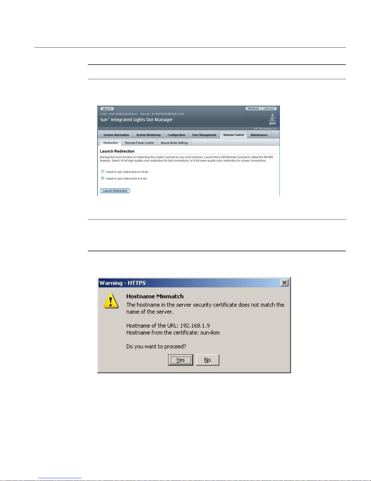
Note – Make sure that the mouse mode is set to Absolute mode in the Mouse Mode Settings tab.
Click 8-bit color or 16-bit color, and then click Launch Redirection.
Note – When using a Windows system for remote console redirection, an additional warning
appears after clicking Launch Redirection. If the Hostname Mismatch dialog box is displayed,
click the Yes button.
The Remote Control dialog box appears.
5
Connecting tothe System Console
55
Page 56
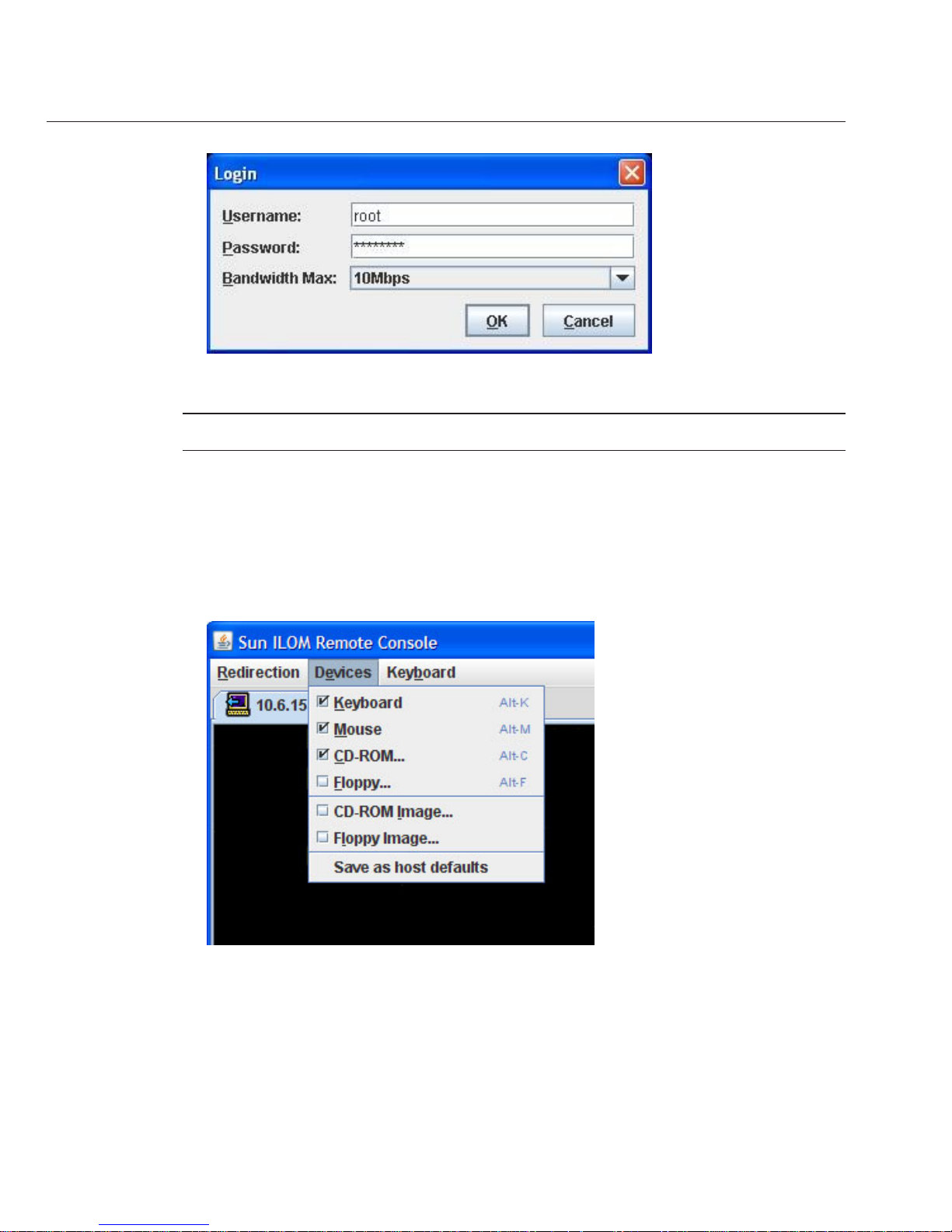
In the Remote ControlLogin dialog box, enter youruser name and password and click OK.
Note – You must have administrator privileges.
The default user name is root and password is changeme.
The JavaRConsole screen appears.
From the Devices menu, select the appropriate item based onthe delivery method you have
chosen.
■
Remote Physical Floppy Disk: Select Floppy to redirect the server to the physical oppy
drive attached to the remote console.
■
Remote Floppy Image: Select Floppy Image to redirect the server to the oppy image le
located on the remote console.
6
7
Connecting tothe System Console
Sun Fire X4600 and Sun FireX4600 M2 Servers InstallationGuide • January 2010, Rev. A56
Page 57

■
Remote Physical CD/DVD: Select CD-ROM to redirect the server to the CD/DVD in the
CD/DVD drive attached to the remote console.
■
Remote CD/DVD Image: Select CD-ROM Image to redirect the server to the .iso image le
located on the remote console .
Note – Using the CD-ROM Remote or CD-ROM Image options to install software on your
server signicantly increases the time necessary to perform the installation because the
content is accessed over the network. The installation duration depends on the network
connectivity and trac.
▼
How to Connect to the Serial Console Using the ILOM Command-Line
Interface
■
Connect the server to your network through an Ethernet cable. See “Server Connections” on
page 45.
■
If you have not already done so, determine the service processor’s IP address. See
“Determining the SP IP Address” on page 47.
Using a client system,establish a Secure Shell (SSH) connection to the service processor’s IP
address:
ssh -l root sp_ip_address
Log in tothe service processor as anadministrator. For example:
login: root
password: changeme
Note – Only accounts with Administratorprivileges are enabled to congure the SP serial port.
See “Conguring Network Settings” in the Sun Integrated Lights Out Manager (ILOM) 3.0 CLI
Procedures Guide.
Start the ILOM consolemode by typing the following:
start /SP/console
If you havechanged the SP Serial Port default settings, makesure you reset them to the default
settings.
BeforeYouBegin
1
2
3
4
Connecting tothe System Console
57
Page 58

58
Page 59

Setting Up Your Operating System
After connecting to the ILOM SP as described in “Communicating With the ILOM and the
System Console” on page 45
, you can congure the optional preinstalled Solaris 10 operating
system (OS), or install a Linux , Windows, or ESX, Solaris operating system.
■
“OS Information Links” on page 59
■
“Conguring the Preinstalled Solaris OS” on page 60
■
“(Optional) How to Redirect the Console Output to the Video Port” on page 63
■
“How to Connect to the Server Using a Serial Capture Program” on page 63
■
“Solaris OS Information Products and Training” on page 64
OS Information Links
Use the appropriate reference, depending on which OS you want to use. For additional OS
considerations, see the
Sun Fire X4600/X4600 M2 Server Product Notes.
OS See Notes
Preinstalled Solaris 10 operating
system
“Conguring the Preinstalled
Solaris OS” on page 60
Solaris 10 OS Sun Fire X4600/X4600 M2 Server
Solaris OS Installation Guide
Also contains procedures for
installing the Solaris operating
system from media
Supported Linux OS and the
required drivers
For assisted OS installation, use the
Sun Installation Assistant. See
Sun
Installation Assistant 2.2 User’s
Guide for the Sun Fire
X4600/X4600 M2 Server
Recommended method
For unassisted OS installation, see
the
Sun Fire X4600/X4600 M2
Server Linux Installation Guide
Alternate method
59
Page 60

OS See Notes
A supported Windows OS and the
required drivers,
For assisted OS installation, use the
Sun Installation Assistant. See
Sun
Installation Assistant 2.2 User’s
Guide for the Sun Fire
X4600/X4600 M2 Server
Recommended method
For unassisted OS installation, see
the
Sun Fire X4600/X4600 M2
Server Windows Installation Guide
Alternate method
A supported ESX OS and the
required drivers
Sun Fire X4600/X4600 M2 Server
ESX Installation Guide
Conguring the Preinstalled Solaris OS
Note – Unlike with SPARC systems, you do not see the output of the preinstalled Solaris 10
image through a monitor when you power on the server. The output of the preinstalled image is
directed to a serial console instead of a monitor that is attached to the server.
Use the Installation Worksheet to gather the information that you need for conguring the OS.
TABLE 3 Installation Worksheet for the PreinstalledSolaris OS
Information for
Installation Description or Example YourAnswers (* = Default)
Language Choose from the list of available languages for the Solaris 10
software.
English*
Locale Choose your geographic region from the list of available
locales.
English (C - 7-bit
ASCII)*
Terminal Choose the type of terminal that you are using from the list of
available terminal types.
Network connection Is the system connected to a network?
■
Networked
■
Non-networked*
DHCP Can the system use Dynamic Host Conguration Protocol
(DHCP) to congure its network interfaces?
■
Yes
■
No*
If you are not using
DHCP, note the
network address
IP address If you are not using DHCP, supply the IP address for the
system.
Example: 129.200.9.1
Conguring the Preinstalled SolarisOS
Sun Fire X4600 and Sun FireX4600 M2 Servers InstallationGuide • January 2010, Rev. A60
Page 61

TABLE 3 Installation Worksheet for the Preinstalled Solaris OS (Continued)
Information for
Installation Description or Example YourAnswers (* = Default)
Subnet If you are not using DHCP, is the system part of a subnet?
If yes, what is the netmask of the subnet?
Example: 255.255.0.0
255.255.0.0*
IPv6 Do you want to enable IPv6 on this machine?
■
Yes
■
No*
Host name A host name that you choose for the system.
Kerberos Do you want to congure Kerberos security on this machine?
If yes, gather the following:
Default Realm:
Administration Server:
First KDC:
(Optional) Additional KDCs:
■
Yes
■
No*
Name service: if the
system uses a name
service, provide the
following
information.
Name service Which name service should this system use?
■
NIS+
■
NIS
■
DNS
■
LDAP
■
None*
Domain name Provide the name of the domain in which the system resides.
NIS+ and NIS Do you want to specify a name server or let the installation
program nd one?
■
Specify One
■
Find One*
DNS Provide IP addresses for the DNS server. You must enter at
least one IP address, but you can enter up to three addresses.
You can also enter a list of domains to search when a DNS
query is made.
Search Domain:
Search Domain:
Search Domain:
Conguring the Preinstalled SolarisOS
61
Page 62

TABLE 3 Installation Worksheet for the Preinstalled Solaris OS (Continued)
Information for
Installation Description or Example YourAnswers (* = Default)
LDAP Provide the following information about your LDAP prole:
Prole name:
Prole server:
If you specify a proxy credential level in your LDAP prole,
gather the following:
Proxy-Bind Distinguished Name:
Proxy-Bind Password:
Default route Do you want to specify a default route IP address or let the
Solaris installation program nd one?
The default route provides a bridge that forwards trac
between two physical networks. An IP address is a unique
number that identies each host on a network.
You have the following choices:
■
You can specify the IP address. An /etc/defaultrouter
le is created with the specied IP address. When the
system is rebooted, the specied IP address becomes the
default route.
■
You can let the Solaris installation program detect an IP
address. However, the system must be on a subnet that has
a router that advertises itself by using the ICMP router
discovery protocol. If you are using the command-line
interface, the software detects an IP address when the
system is booted.
■
You can choose None if you do not have a router or do not
want the software to detect an IP address at this time. The
software automatically tries to detect an IP address on
reboot.
■
Specify One
■
Detect One
■
None*
Time zone How do you want to specify your default time zone?
■
Geographic region*
■
Oset from GM
■
Time zone le
Root password Choose a root password for the system.
Conguring the Preinstalled SolarisOS
Sun Fire X4600 and Sun FireX4600 M2 Servers InstallationGuide • January 2010, Rev. A62
Page 63

▼
(Optional) How to Redirect the Console Output to theVideo Port
Caution – This procedure is intended for advanced users of the Solaris OS only. You can
seriously disrupt the proper functioning of the server or render the server unbootable if you
introduce a problem in the bootenv.rc le.
This procedure assumes you are connected to the server using the SP's IP address. See
“Determining the SP IP Address” on page 47.
Run the eeprom command atthe prompt using the following arguments:
/eeprom console=text/
▼
How to Connect to the Server Using a Serial Capture Program
Use a cable toconnect the serial port of the server tothe serial port of the serial capture host
system.
Make sure thatthe communication properties of the serial port of the system are set to the
default.
The default settings are 9600 baud, 8, N, 1 (eight data bits, no parity, one stop bit), disable ow
control.
Start a terminal session to capturethe serial port output:
On a client running Solaris OS, type:
$tip -9600 /dev/ttya
On a client running Windows, start a program such as Hyperterminal.
On a client running Linux, start a program such as Minicom, a text-based serial communication
program that is included in the Linux distributions. For more information, see the man pages
included in the Linux distribution.
Log in tothe service processor as anAdministrator, for example:
login: root password: changeme
Start the ILOM SPGUI by typing the following:
start /SP/console
Poweron main power to the server by usinga ball-point pen or other pointed object to press the
recessed Power button on the front panel.
POST messages appear on your screen as the OS starts.
BeforeYouBegin
●
1
2
3
4
5
6
Conguring the Preinstalled SolarisOS
63
Page 64

Follow theSolaris 10 software onscreen prompts.
Use the informationthat you gathered in
“Conguringthe Preinstalled Solaris OS”on page 60 to
help you enterthe system and network information as youare prompted.
The screens that are displayed vary, depending on the method that you chose for assigning
network information to the server (DHCP or static IP address).
After you entered the system-conguration information, the server completes the boot process
and displays the Solaris login prompt.
Seethe Solaris 10 OS user documentation at:
http://docs.sun.com/app/docs/prod/solaris.10
Solaris OS Information Products and Training
You can access the various collections of the Solaris 10 OS user documentation at:
http://docs.sun.com/app/docs/prod/solaris.10
Sun provides exible training options that accommodate your personal schedule and learning
style. The training options include instructor-led, web-based online, CD-ROM and Live Virtual
Class. For Solaris 10 Training and Certication options at a glance, please visit:
http://www.sun.com/training/catalog/operating_systems/index.xml
7
8
See Also
Solaris OSInformation Products and Training
Sun Fire X4600 and Sun FireX4600 M2 Servers InstallationGuide • January 2010, Rev. A64
Page 65

Index
A
attaching cable management arm, 24-26
C
cable management arm
attaching, 24-26
overview, 23
removing, 27
verifying operation, 26-27
cabling, 33
CLI
accessing via serial management port, 48-49, 49-51
accessing via SSH, 49
CMA, See cable management arm
compatible racks, 16
connecting
to physical console, 52
to remote console, 52-57
to serial console, 57
connecting to the ILOM CLI
using serial management port, 48-49, 49-51
using SSH, 49
connecting to the ILOM web interface, 51
connectors, 45
console
connecting directly, 52
connecting remotely, 52-57
serial connection, 57
console output, 63
contents of the box, 15
D
direct connection to console, 52
E
equipment, 16
ESX OS, 59-64
F
nding the serial number, 39
I
ILOM SP, See service processor
inserting server, 21-22
installation, steps, 15-27
installation worksheet, 60
installing
server, prerequisites, 16
server into rack, 21-22
slide rails, 19-21
L
Linux OS, 59-64
65
Page 66

O
operating system, 59-64
P
physical console, connecting directly, 52
powering on or o the server, 35-36
preinstalled Solaris OS, 60
prerequisites for installing hardware, 16
R
racks, 16
redirecting console output to video port, 63
reducing weight, 19
remote console, connecting, 52-57
removing cable management arm, 27
removing components to reduce weight, 19
removing server, 29-32
S
serial console, connecting, 57
serial management port
connecting to the ILOM CLI, 48-49, 49-51
serial number, 39
server
back panel, 33
cabling, 33
inserting into rack, 21-22
powering o, 37-38
powering on, 35-36
removing, 29-32
serial number, 39
server connectors, 45
service, requesting, 39
service processor interfaces, 47
service processor IP addresses, overview, 47
setting up OS, 59-64
slide rail kit, 17
slide rails, 19-21
slide-rails, verifying operation, 22-23
Solaris, worksheet, 60
Solaris OS
overview, 59-64
preinstallation conguration, 60
SSH, connecting to the ILOM CLI, 49
sta required, 16
T
tools required, 16
V
verifying slide-rails, 22-23
video port, 63
W
web ILOM interface, 51
weight, reducing, 19
Windows OS, 59-64
worksheet, Solaris, 60
Index
Sun Fire X4600 and Sun FireX4600 M2 Servers InstallationGuide • January 2010, Rev. A66
 Loading...