


Sun Fire™X4500/X4540 Servers
Administration Guide
Sun Microsystems, Inc.
www.sun.com
Part No. 819-6562-16
October 2008, Revision A
Submit comments about this document at: http://www.sun.com/hwdocs/feedback

Copyright ©2008 Sun Microsystems, Inc., 4150Network Circle,Santa Clara, California 95054, U.S.A.All rights reserved.
This distributionmay include materials developed bythird parties. Sun, Sun Microsystems,the Sun logo, Java, Netra,Solaris, Sun Ray and Sun
Fire X4540Backup Server are trademarks or registered trademarks of SunMicrosystems, Inc.,and its subsidiaries, in theU.S. and other
countries.
This product is covered and controlled by U.S. Export Control laws and may be subject to the export or import laws in other countries. Nuclear,
missile, chemical biological weapons or nuclear maritime end uses or end users, whether direct or indirect, are strictly prohibited. Export or
reexport to countries subject to U.S. embargo or to entities identified on U.S. export exclusion lists, including, but not limited to, the denied
persons and specially designated nationals lists is strictly prohibited. Use of any spare or replacement CPUs is limited to repair or one-for-one
replacement of CPUs in products exported in compliance with U.S. export laws. Use of CPUs as product upgrades unless authorized by the
U.S. Government is strictly prohibited.
Copyright ©2008 Sun Microsystems, Inc., 4150Network Circle,Santa Clara, California 95054, Etats-Unis.Tousdroits réservés.
Cette distributionpeut incluire des élements développés par des tiers. Sun, Sun Microsystems, le logo Sun, Java,Netra, Solaris, Sun Ray etSun
Fire X4540Backup Server sont des marques de fabriqueou des marques déposées deSun Microsystems,Inc., et ses filiales, auxEtats-Unis et
dans d'autrespays.
Ce produit est soumis à la législation américaine sur le contrôle des exportations et peut être soumis à la règlementation en vigueur dans
d'autres pays dans le domaine des exportations et importations. Les utilisations finales, ou utilisateurs finaux, pour des armes nucléaires, des
missiles, des armes biologiques et chimiques ou du nucléaire maritime, directement ou indirectement, sont strictement interdites. Les
exportations ou reexportations vers les pays sous embargo américain, ou vers des entités figurant sur les listes d'exclusion d'exportation
américaines, y compris,mais de manierenon exhaustive, la liste de personnes quifont objet d'un ordre de ne pas participer,d'une façon directe
ou indirecte, aux exportations des produits ou des services qui sont régis par la législation américaine sur le contrôle des exportations et la liste
de ressortissants spécifiquement désignés, sont rigoureusement interdites. L'utilisation de pièces détachées ou d'unités centrales de
remplacement est limitée aux réparations ou à l'échange standard d'unités centrales pour les produits exportés, conformément à la législation
américaine en matière d'exportation. Saufautorisation par lesautorités des Etats-Unis,l'utilisation d'unités centralespour procéder à des mises
à jour de produits est rigoureusement interdite..
Please
Recycle

Contents
Preface ix
Part I Sun Fire X4500 Server Administration Guide
1. Introduction to the Sun Fire X4500 Server 1
Features of the Server 1
Exterior Features, Controls, and Indicators 3
Front Panel 3
Disk Drive and Fan Tray LEDs 6
About Reliability, Availability, and Serviceability Features 9
Hot-Pluggable and Hot-Swappable Components 9
Hot Pluggable Components Overview 10
Hot Swappable Components Overview 10
2. Software and Operating Environment 11
Using the Zettabyte File System (ZFS) 11
About ZFS 12
Administering ZFS File Systems 12
12
Integrated Lights Out Manager ILOM 13
Intelligent Platform Management (IPMI) 13
iii

3. Identifying and Configuring Components 15
Solaris System Commands 15
prtconf Command 16
prtdiag Command 17
psrinfo Command 18
showrev Command 18
cfgadm Command 19
Component Configuration Information 22
Attachment Points Overview 22
Determining Attachment Points 23
Changing to Attachment Points 23
States and Conditions 24
Drive and Drive Slot States 24
Drive Conditions 25
Component States 25
4. Disk Administration and Management 27
Hard Disk Drive Locations 27
Disk Drive Status and LEDs 29
EFI Disk Label Overview 30
Converting EFI Label to SMI (Solaris) Label On The Sun Fire X4500 Disk 31
Adding Disks 34
Adding a Disk to a Mirrored ZFS Configuration 36
Replacing a Device in a ZFS Storage Pool 37
Removing a Disk From Service 37
Correcting Unconfigure Operation Failure 38
Unconfiguring a Disk in Use 38
5. Sun Fire X4500 Fault Management Architecture 41
iv Sun Fire X4500/ X4540 Servers Administration Guide • October 2008

Fault Management Architecture Overview 41
Sun Fire X4500 Fault Management Utility Commands 42
fmd Command 43
fmdump Command 44
Diagnosing Disk Faults 44
Clearing Disk Faults 46
Using thefmadm Command to Clear Faults 46
Displaying Fault Statistics Using the fmstat Command 47
6. Rebuilding the Preinstalled OS 49
Preinstalled OS Overview 49
Creating Preinstalled OS Disk Mirrors (RAID-1) 50
metadb Command 51
metainit Command 51
metaroot Command 52
Recreating the Preinstalled OS 52
Create a Mirror for the root (/) File System 53
Create a Mirror for the swap Partition 54
Create a Mirror for the /var Partition 54
Create / root, /swap, and /var Mirrors 55
Attach / root, /swap, and /var Mirrors 55
Display Current Status of the Metadevices 56
Install GRUB on the Boot Disk 56
Configure the Alternate Boot Device 57
7. Using Disk Control and Monitor Utility (DCMU) 59
Overview of the Disk Control and Monitor Utility 59
Using DCMU 60
cfgdisk Command 60
Contents v

cfgdisk Command Options 60
Examples Using the cfgdisk Command 60
hotplugmon 61
faultmond Command 61
Examples Using the faultmond Command 62
Part II Sun Fire X4540 Server Administration Guide
8. Introduction to the Sun Fire X4540 Server 65
X4540 Server Features 65
Exterior Features, Controls, and Indicators 67
Front Panel 67
Disk Drive and Fan Tray LEDs 71
About Reliability, Availability, and Serviceability Features 74
Hot-Pluggable and Hot-Swappable Components 74
Hot-pluggable Components Overview 75
Hot-swappable Components Overview 75
9. Software and Operating Environment 77
About ZFS 77
Overview 78
Devices 78
Structure 78
Using the ZFS File System 79
Additional information 79
About Integrated Lights Out Manager (ILOM) 79
About Intelligent Platform Management (IPMI) 80
10. Identifying and Configuring Components 81
Solaris System Commands 81
vi Sun Fire X4500/ X4540 Servers Administration Guide • October 2008

prtconf Command 82
prtdiag Command 83
psrinfo Command 84
showrev Command 85
cfgadm Command 85
Component Configuration Information 89
Attachment Points Overview 89
Determining Attachment Points 90
Changing to Attachment Points 90
States and Conditions 91
Drive and Drive Slot States 91
Drive Conditions 92
Component States 92
11. Managing Hard Disk Drives 93
Hard Disk Drive Locations 93
Disk Drive Status and LEDs 95
EFI Disk Label Overview 96
Converting EFI Label to SMI (Solaris) Label on the Sun Fire X4540 Disk 97
About HDtool 101
Removing a Disk From Service 101
Correcting Unconfigure Operation Failure 102
Adding a Disk 103
Checking Disk Usage 104
12. Sun Fire X4540 Fault Management Architecture 107
Fault Management Architecture Overview 107
Sun Fire X4540 Fault Management Utilities 108
fmd Command 109
Contents vii

fmdump Command 110
Using the fmdump Command to Identify Faults 110
Diagnosing Disk Faults 111
Clearing Disk Faults 112
fmadm Command 112
Using the fmadm Command to Clear Faults 112
Displaying Fault Statistics Using the fmstat Command 113
13. Rebuilding the Preinstalled OS 115
Preinstalled OS Overview 115
Creating Preinstalled OS Disk Mirrors (RAID-1) 116
metadb Command 117
metainit Command 117
metaroot Command 118
Re-creating the Preinstalled OS 118
Create a Mirror for the root (/) File System 119
Create a Mirror for the swap Partition 120
Create a Mirror for the /var Partition 120
Create /root, /swap, and /var Mirrors 120
Attach /root, /swap, and /var Mirrors 121
Display Current Status of the Metadevices 121
Install GRUB on the Boot Disk 122
Configure the Alternate Boot Device 123
Glossary 125
Index 139
viii Sun Fire X4500/ X4540 Servers Administration Guide • October 2008

Preface
How This Book Is Organized
This manual consists of two parts:
The Sun Fire X4500 Server Administration Guide describes how to perform various
administration, configuration, and monitoring tasks associated with the Sun Fire™
X4500 Server.
This guide contains the following chapters:
■ Chapter 1 provides an introduction to the Sun Fire X4500 server information.
■ Chapter 2 provides system and operating environment information.
■ Chapter 3 provides information on how to identify and configure components.
■ Chapter 4 provides hard disk management information.
■ Chapter 4 provides disk administration and management information.
■ Chapter 5 provides fault management architecture information.
■ Chapter 6 provides information about how to rebuild the preinstalled OS.
The Sun Fire X4540 Server Administration Guide describes how to administer,
configure, and monitor the Sun Fire™ X4540 Server.
This guide contains the following chapters:
■ Chapter 8 provides an introduction to the Sun Fire X4540 server information.
■ Chapter 9 provides system and operating environment information.
■ Chapter 10 provides information on how to identify and configure
components.
■ Chapter 11 provides hard disk management information.
ix

■ Chapter 13 provides disk administration and management information.
■ Chapter 12 provides fault management architecture information.
■ Chapter 13 provides information about how to rebuild the preinstalled OS.
Before You Read This Book
It is important that you review the safety guidelines in the Safety and Compliance
Guide (819-4365).
This document is intended for the Sun Fire system administrator, who has a working
knowledge of UNIX® systems, particularly those based on the Solaris™ Operating
System (OS). If you do not have this knowledge, read the Solaris User and System
Administrator documentation provided with your system, and consider UNIX
system administration training.
Related Documentation
Sun Fire X4500 Specific Documents
Refer to the Sun Fire X4540 Server Installation Guide (819-4358) for system installation
information with default settings.
The Sun Fire X4500 specific documents listed in the following table are available at:
http://docs.sun.com/app/docs/prod/sf.x4500#hic
Application Title Part Number
System setup information Sun Fire X4500 Server Installation Guide 819-4358
Overview and service information Sun Fire X4500 Server Diagnostics Guide 819-4363
Product Notes Sun Fire X4500 Server Product Notes 819-4364
Safety information Sun Fire X4500 Server Safety and Compliance Guide 819-4365
x Sun Fire X4500/ X4540 Servers Administration Guide • October 2008

Sun Fire X4540 Specific Documents
The Sun Fire X4540 specific documents listed in the following table are available at:
http://docs.sun.com/app/docs/prod/sf.X4540#hic
Application Title Part Number
System setup information Sun Fire X4540 Server Installation Guide 819-4358
Overview and service information Sun Fire X4540 Server Diagnostics Guide 819-4363
Product Notes Sun Fire X4540 Server Product Notes 819-4364
Safety information Sun Fire X4540 Server Safety and Compliance Guide 819-4365
General Documents
The related general documents listed in the following table are available at:
http://docs.sun.com
Application Title Part Number
hdtool x64 Servers Utilities Reference Manual 820-1120
Solaris basic administration System Administration Guide: Basic Administration 817-1985
Solaris advanced administration System Administration Guide: Advanced Administration 817-0403
Solaris device and file system
administration
Solaris Volume Manager
administration
ZFS administration ZFS (Zettabyte File System) Administration Guide 819-5461
System Administration Guide: Devices and File Systems 817-5093
Solaris Volume Manager Administration Guide 819-2789
Preface xi

Documentation, Support, and Training
Sun Function URL Description
Documentation http://docs.sun.com/app/ Download PDF and HTML documents,
and order printed documents.
Support and
training
http://www.sun.com/support/
http://www.sun.com/training/
Obtain technical support, download
patches, and learn about Sun courses.
Sun Welcomes Your Comments
Sun is interested in improving its documentation and welcomes your comments and
suggestions. You can submit comments to:
http://www.sun.com/hwdocs/feedback
Please include the title and part number of your document with your feedback:
Sun Fire X4500/X4540 Servers Administration Guide, (819-6562-16).
xii Sun Fire X4500/ X4540 Servers Administration Guide • October 2008

PA R T
I Sun Fire X4500 Server Administration
Guide
This part contains the Sun Fire X4500 Server Administration Guide and includes the
following chapters:
■ Chapter 1 provides an introduction to the Sun Fire X4500 server information.
■ Chapter 2 provides system and operating environment information.
■ Chapter 3 provides information on how to identify and configure components.
■ Chapter 4 provides hard disk management information.
■ Chapter 4 provides disk administration and management information.
■ Chapter 5 provides fault management architecture information.
■ Chapter 6 provides information about how to rebuild the preinstalled OS.


CHAPTER
1
Introduction to the Sun Fire X4500 Server
This chapter introduces you to the Sun Fire X4540 Server and describes some of its
features.
The following information is covered in this chapter:
■ “Features of the Server” on page 1
■ “Exterior Features, Controls, and Indicators” on page 3
Features of the Server
The Sun Fire X4500 server is a mid-level, modular, rack-optimized server in the Sun
x64 product family. The family platform includes servers engineered for AMD
Opteron CPUs and deployment into commercial server markets in a slide-mounted,
horizontally biased enclosure for rack cabinet installations, primarily in datacenter
locations.
The server provides the following maximum system configurations:
■ 8 DDR-I DIMM slots (4 per processor), up to 2 GB per DIMM (16 GB per system)
■ Up to forty-eight 3.5 SATA Type-1 drives, of 250 GB-500 GB capacity each (over 24
TB total system capacity)
■ Two 133 MHz PCI-X slots
■ 4 USB ports
Standard I/O includes four 10/100/1000BASE-T Gigabit Ethernet ports, VGA video,
serial, four USB ports, and one 10/100BASE-T Gigabit Ethernet management port.
1

The Sun Fire X4500 server includes an extensive set of reliability, availability, and
serviceability (RAS) features, such as hot-pluggable and redundant hard disk drives
(when RAID1 is used), and hot-swappable fans, and power supplies. The servers
also provide an Integrated Lights Out Management (ILOM) service processor
function that includes remote boot and remote software upgrades.
TABLE 1-1 summarizes the features of the Sun Fire X4500 server.
TABLE 1-1 Summary of X4500 Server Features
Feature or
Component Sun Fire X4500 Server
CPU Two Revision E AMD64 Opteron dual-core processors on two CPU
modules.
Processor BIOS 8-Mbit Flash with LPC interface.
Memory 8 DDR-I DIMM slots (4 per processor), up to 2 GB per DIMM (16 GB
per system).
Hard disk drives
(HDDs)
Service Processor Integrated Lights Out Manager (ILOM) as described in the ILOM
RAID options RAID is done through software.
Network I/O • Four 10/100/1000BASE-T Gigabit Ethernet ports (RJ-45 connectors)
PCI I/O Two 133-MHz low-profile PCI-X slots.
Other I/O • Four USB 2.0 ports
Power 1500 W DC max output per power supply, two bays, 1+1 redundancy,
Fans Five fan modules; also additional fans in each power supply.
Up to forty-eight 3.5 SATA Type-1 drives, of 250 GB-500 GB capacity
each (over 24 TB total system capacity).
documentation (see the Integrated Lights Out Manager (ILOM)
Administration Guide (819-0280).
• One 10/100BASE-T Ethernet net management port (RJ-45
Connector)
• One RS-232 serial port (RJ-45 Connector)
• One VGA video port
hot swappable.
1130 W AC max system input power = 3856 BTU/hr = 0.321 Tons of
Air Conditioning, 200–240 VAC.
Cooling is front-to-back forced air.
2 Sun Fire X4500/ X4540 Servers Administration Guide • October 2008

Exterior Features, Controls, and Indicators
This section describes the features, controls, and indicators on the front and rear
panels of the Sun Fire X4500 server.
Front Panel
FIGURE 1-2 shows the front panel.
FIGURE 1-1 Sun Fire X4500 Server Front Panel
USB connectors
FIGURE 1-1 shows a close up of the controls and indicators.
Serial number labels on ledge
Chapter 1 Introduction to the Sun Fire X4500 Server 3

FIGURE 1-2 Sun Fire X4500 Server Front Panel Controls and Indicators
(1)
TABLE 1-2 Sun Fire X4500 Server Front Panel
# Name Color Description
1 Locate
(2) (3) (4)
(5) (6)
White Operators can turn this LED on remotely
button/LED
(7)
to help them locate the server in a
crowded server room. Press to turn off.
2 System Fault Amber On - When service action is required.
3 Power/Operation Green Steady - Power is on.
Blink - Standby power is on but main
power is off.
Off - Power is off.
4 System power
button
Grey To power on main power for all the
server components.
4 Top failure LED Amber On - HDD or fan fault.
6 Rear failure LED Amber On - Power supply or system controller
fault (service is required).
7 Over temperature
Amber On - When system is over temperature.
LED
FIGURE 1-3 shows features of the rear panel.
4 Sun Fire X4500/ X4540 Servers Administration Guide • October 2008

FIGURE 1-3 Sun Fire X4500 Server Rear Pane
(1)
(5) (6)
(7) (8) (9) (12)(10)
(11) (13) (14)
(4)
TABLE 1-3 Sun Fire X4500 Server Rear Panel
(2)
(3)
# Name Description
1 AC power connectors Each power supply has its own AC connector with a
clip to secure its power cable.
2 Chassis ground Connect grounding straps here.
3 Mounting plate for CMA
bracket
Use this mounting plate to secure the CMA (optional).
Refer to the Sun Fire X4500 Server Installation Guide.
4 PCIX-0 and PCIX-1 Slots for PCIX cards.
5 NET MGT (S) Net management and service processor port.
6 Video connector Connect video monitor.
7 SER MGT Serial management port (serial connection to service
processor).
Chapter 1 Introduction to the Sun Fire X4500 Server 5

# Name Description
8 Locate button/LED White
Operators can turn this LED on remotely to help them
locate the server in a crowded server room. Press to
turn off.
9 Fault LED Amber – When on, service action required.
10 OK LED Green – Service action allowed.
When on, service action is required.
Blink – Standby power is On but main power is off.
11 USB connectors Connect USB devices.
12 10/100/1000 gigabit
Ethernet ports
13 System controller status
LEDs
Connect server to Ethernet.
Blue – Ready to remove.
Amber – Fault, service action required.
Green – Operational, no action required.
14 NMI and reset buttons Do not use these buttons unless instructed by Sun
service personnel. To operate these buttons, insert a
stylus or a straightened paper clip into the recess.
• NMI – Non-Maskable Interrupt dump. Sends an NMI
to the CPU. Used for debugging only.
• Reset – Resets the CPU but not the service processor
Disk Drive and Fan Tray LEDs
FIGURE 1-4 shows the location of the internal LEDs. FIGURE 1-5 shows a close-up view
of the disk drive and fan trays, including the symbols that identify the LEDs.
6 Sun Fire X4500/ X4540 Servers Administration Guide • October 2008

FIGURE 1-4 Disk Drive Locations
Chapter 1 Introduction to the Sun Fire X4500 Server 7

FIGURE 1-5 Disk Drive and Fan Tray LEDs
8 Sun Fire X4500/ X4540 Servers Administration Guide • October 2008

About Reliability, Availability, and Serviceability Features
Reliability, availability, and serviceability (RAS) are aspects of a system’s design that
affect its ability to operate continuously and to minimize the time necessary to
service the system.
Reliability refers to a system’s ability to operate continuously without failures and to
maintain data integrity. System availability refers to the percentage of time that a
system remains accessible and usable. Serviceability relates to the time it takes to
restore a system to service following a system failure. Together, reliability,
availability, and serviceability features provide for near continuous system
operation.
To deliver high levels of reliability, availability and serviceability, the Sun Fire X4500
Server system offers the following features:
■ Hot-pluggable disk drives
■ Redundant, hot-swappable power supplies
■ Environmental monitoring and fault protection
■ Integrated Lights Out Management (ILOM) Sun’s remote management capability
■ Support for disk and network multipathing with automatic failover capability
■ Error correction and parity checking for improved data integrity
■ Easy access to all internal replaceable components
■ Full in-rack serviceability by extending the slides
Hot-Pluggable and Hot-Swappable Components
Sun Fire X4540 Server hardware is designed to support hot-pluggable and
hot-swappable components. Hot plugging and hot swapping are cost-effective
solutions that provides increased system availability and continuous serviceability
for business-critical computing environments, by providing the ability to:
■ Remove or replace a failed or failing component while the system is operating
without service disruption.
■ Increase storage capacity dynamically to handle larger work loads and improve
system performance.
Chapter 1 Introduction to the Sun Fire X4500 Server 9

Hot Pluggable Components Overview
The Sun Fire X4500 server hot-plug technology allows a component to be added,
upgraded, or replaced while the system is running without affecting hardware
integrity.
Hot-plugging provides the ability to physically add, remove, or replace a hard disk
drive while the system is running, and other hard disks in the system provide
continuous service. Before a hot-pluggable component is removed from the Sun Fire
X4500 server, the component must be taken offline from the operating system first,
but does not require that the server be powered off.
On the Sun Fire X4500 server, you can hot-plug the following components:
TABLE 1-4 Sun Fire X4500 Hot-Pluggable Devices (Partial List)
Component Part Number
250 GB SATA 3.5 Hard Disk Drive 541-1467
500 GB SATA 3.5 Hard Disk Drive 541-1468
For instructions on hot-plugging components, see the following:
■ cfgadm Command in Chaper 3.
■ cfgadm(1M) (See the cfgadm(1M) man page for more information.)
Hot Swappable Components Overview
A hot swappable component is a component that can be removed or replaced
without affecting software integrity. This means that when a component is removed
it does not need to be taken offline from the operating system first.
On the Sun Fire X4500 server, you can hot-swap the following components:
TABLE 1-5 Sun Fire X4500 Hot-Swappable Devices (Partial List)
Component Part Number
Power supply (type A205) 300-178
Fan module 541-0458
For more information about updating the Sun Fire X4500 Server, product updates, or
for the most up-to-date list of replaceable components, refer to the Sun Fire X4500
Server Service Manual (819-4359), and the Sun Fire X4500 Server Product Notes (819-
4364).
10 Sun Fire X4500/ X4540 Servers Administration Guide • October 2008

CHAPTER
2
Software and Operating Environment
The Sun Fire X4500 server supports Solaris 32-bit and 64-bit operating systems. The
system is shipped with Integrated Lights Out Manager (ILOM) and Solaris 10 6/06
operating system which includes the newly designed Zettabyte File System (ZFS).
This chapter includes the following topics:
■ “Using the Zettabyte File System (ZFS)” on page 11
■ “Administering ZFS File Systems” on page 12
■ “Integrated Lights Out Manager ILOM” on page 13
■ “Intelligent Platform Management (IPMI)” on page 13
Using the Zettabyte File System (ZFS)
This section provides information about using Zettabyte File Systems (ZFS) on the
Sun Fire X4500 server. Concepts such as hierarchical file system layout, property
inheritance, and automatic mount point management and share interactions are
included in the ZFS Administration Guide, (819-5461). For information on best
practices for ZFS go to:
http://www.solarisinternals.com/wiki/index.php/ZFS_Best_Practices_Guide
The Solaris Zettabyte File System (ZFS), is available in the Solaris 10 11/06 OS and
delivers file system management capabilities by automating common administrative
tasks, protecting data from corruption and providing virtually unlimited scalability.
ZFS uses virtual storage pools to make it easy to expand or contract file systems
simply by adding more drives.
11

A Zettabyte File System is a lightweight POSIX file system that is built on top of a
storage pool. File systems can be dynamically created and destroyed without
requiring you to allocate or format any underlying space. Because file systems are so
lightweight and because they are the central point of administration in ZFS, you are
likely to create many of them.
About ZFS
ZFS is a 128-bit file system that provides 16 billion times the capacity of 32-bit or
even 64-bit file systems. With ZFS, data is protected by 64-bit checksums to provide
error detection and correction functionally. It constantly reads and checks data to
ensure that it is correct. If it detects an error in a mirrored pool, the technology
automatically repairs the corrupted data.
Historically, file systems have been constrained to one device so that the file systems
themselves have been constrained to the size of the device. Creating and re-creating
traditional file systems because of size constraints are time-consuming and
sometimes difficult. Traditional volume management products helped manage this
process.
Because ZFS file systems are not constrained to specific devices, they can be created
easily and quickly, similar to the way directories are created. ZFS file systems grow
automatically within the space allocated to the storage pool.
Instead of creating one file system, such as /export/home, to manage many user
subdirectories, you can create one file system per user. In addition, ZFS provides a
file system hierarchy so that you can easily set up and manage many file systems by
applying properties that can be inherited by file systems contained within the
hierarchy.
Administering ZFS File Systems
You administer ZFS file systems by using the zfs command. This command
provides a set of subcommands that perform specific operations on file systems. You
can also manage snapshots, volumes, and clones by using this command, but these
features are covered only briefly in this chapter.
With ZFS you can perform the following administrative functions:
■ Manage Devices
■ Create File Systems
■ Create and Manage Storage Pools
12 Sun Fire X4500/ X4540 Servers Administration Guide • October 2008

■ Create and Manage Volumes
■ Take a Snapshot of a File System or Volume
For more information about ZFS, and for an example of creating a file system, refer
to the ZFS Administration Guide, (819-5461).
Integrated Lights Out Manager ILOM
Integrated Lights Out Manager (ILOM) is an Intelligent Platform Management
Interface (IPMI) 2.0-compliant Baseboard Management Controller (BMC) that
implements Lights Out Management (LOM), including Remote Keyboard, Video,
Mouse, and Storage (RKVMS); a Web management interface; a command line
interface (CLI); and Simple Network Management Protocol (SNMP).
The ILOM software includes the following:
■ Embedded, hardened Linux OS
■ IPMI 2.0 BMC
■ Platform Control agents diagnostics software
■ RKVMS
Lights Out Management is performed on the Sun Fire X4500 server through
IPMItool, a command-line utility for controlling IPMI-enabled devices. For more
information about Integrated Lights Out Manager (ILOM, refer to the Integrated
Lights Out Manager (ILOM) Administration Guide, (819-1160).
Intelligent Platform Management (IPMI)
Intelligent Platform Management (IPMI) refers to the autonomous monitoring,
logging, recovery, and inventory control features implemented in hardware and
firmware. There are two major components of platform management: the Service
Processor (or BMC) and System Management Software (SMS). Platform status
information can be obtained and recovery actions initiated under situations in which
system management software and normal in-band management mechanisms are
unavailable.
SNMP (Simple Network Management Protocol) is a network management protocol
used almost exclusively in TCP/IP networks. It provides remote access by
SNMP-compliant entities to monitor and control network devices and to manage
configurations, statistics collection, performance, and security on a network
Chapter 2 Software and Operating Environment 13

IPMI messages can be used to communicate with the BMC over serial and LAN
interfaces, so software designed for in-band (local) management can be re-used for
out-of-band (remote) management simply by changing the low-level
communications layer.
The IPMItool is a simple command-line interface to systems that support the IPMI
v2.0 specification. IPMItool provides the ability to read the sensor data repository
and print sensor values, display the contents of the system event log, and SNMP.
14 Sun Fire X4500/ X4540 Servers Administration Guide • October 2008

CHAPTER
3
Identifying and Configuring Components
This chapter introduces the tools that let you administer the server and explains how
the diagnostic tools fit together.
Topics in this chapter include:
■ “Solaris System Commands” on page 15
■ “Component Configuration Information” on page 22
The Sun Fire X4500 server and its accompanying software contain tools and features
that help you:
■ Isolate problems when there is a failure of a field-replaceable component
■ Monitor the status of a functioning system
■ Exercise the system to disclose an intermittent or incipient problem
For detailed instructions on diagnosing the server, refer to the Sun Fire X4500 Server
Diagnostics Guide (819-4363) and the Sun Fire X4500 Server Service Manual (819-4359).
Solaris System Commands
Some Solaris commands display data that you can use when assessing the condition
of a Sun Fire X4500 server. This section discusses superuser commands that assist in
troubleshooting problems with the Sun Fire X4500 server. These commands include:
■ “prtconf Command” on page 16
■ “prtdiag Command” on page 17
■ “psrinfo Command” on page 18
■ “cfgadm Command” on page 19
15

This section describes the information these commands give you. For additional
information about these commands, see the command man pages.
prtconf Command
The prtconf command displays the Solaris device tree. This tree includes all the
devices probed by the firmware, as well as additional devices, like individual disks,
that only the operating environment software can detect. The output of prtconf
also includes the total amount of system memory.
CODE EXAMPLE 3-1 prtconf Command Output
# prtconf -p
System Configuration: Sun Microsystems i86pc
Memory size: 8096 Megabytes
System Peripherals (PROM Nodes):
The prtconf command’s -p option produces output similar to the show-devs
command. The show-devs command lists only those devices compiled by the
system firmware.
16 Sun Fire X4500/ X4540 Servers Administration Guide • October 2008

prtdiag Command
The prtdiag command displays a table of diagnostic information that summarizes
the status of system components.
CODE EXAMPLE 3-2 prtdiag Command Output
# prtdiag
System Configuration: Sun Microsystems Sun Fire X4500
BIOS Configuration: American Megatrends Inc. 080010 06/15/2006
BMC Configuration: IPMI 2.0 (KCS: Keyboard Controller Style)
==== Processor Sockets ====================================
Version Location Tag
-------------------------------- -------------------------Dual Core AMD Opteron(tm) Processor 285 H0
Dual Core AMD Opteron(tm) Processor 285 H1
==== Memory Device Sockets ================================
Type Status Set Device Locator Bank Locator
------- ------ --- ------------------- -------------------DDR in use 0 H0_DIMM0 BANK0
DDR in use 0 H0_DIMM1 BANK1
DDR in use 0 H0_DIMM2 BANK2
DDR in use 0 H0_DIMM3 BANK3
DDR in use 0 H1_DIMM0 BANK4
DDR in use 0 H1_DIMM1 BANK5
DDR in use 0 H1_DIMM2 BANK6
DDR in use 0 H1_DIMM3 BANK7
==== On-Board Devices =====================================
Marvell serial-ATA #1
Marvell serial-ATA #2
Marvell serial-ATA #3
Marvell serial-ATA #4
Marvell serial-ATA #5
Marvell serial-ATA #6
Intel 82546EB #1
Intel 82546EB #2
Intel 82551QM
==== Upgradeable Slots ====================================
ID Status Type Description
--- --------- ---------------- ---------------------------0 in use PCI-X PCIX0
1 available PCI-X PCIX1
Chapter 3 Identifying and Configuring Components 17

psrinfo Command
The psrinfo command displays the date and time each CPU came online. With the
verbose (-v) option, the command displays additional information about the CPUs,
including their clock speed. The following is sample output from the psrinfo
command with the -v option.
CODE EXAMPLE 3-3 psrinfo -v Command Output
# psrinfo -v
Status of virtual processor 0 as of: 08/03/2006 17:49:11
on-line since 08/02/2006 16:28:42.
The i386 processor operates at 2593 MHz,
and has an i387 compatible floating point processor.
Status of virtual processor 1 as of: 08/03/2006 17:49:11
on-line since 08/02/2006 16:28:49.
The i386 processor operates at 2593 MHz,
and has an i387 compatible floating point processor.
Status of virtual processor 2 as of: 08/03/2006 17:49:11
on-line since 08/02/2006 16:28:51.
The i386 processor operates at 2593 MHz,
and has an i387 compatible floating point processor.
Status of virtual processor 3 as of: 08/03/2006 17:49:11
on-line since 08/02/2006 16:28:53.
The i386 processor operates at 2593 MHz,
and has an i387 compatible floating point processor.
showrev Command
The showrev command displays revision information for the current hardware and
software. Code example 3-4 shows sample output of the showrev command.
CODE EXAMPLE 3-4 showrev Command Output
# showrev
Hostname: abc-123
Hostid: cc0ac37f
Release: 5.10
Kernel architecture: i86pc
Application architecture: i386
Hardware provider: Sun_Microsystems
Domain: Sun.COM
Kernel version: SunOS 5.10 Generic_11122-15
18 Sun Fire X4500/ X4540 Servers Administration Guide • October 2008

cfgadm Command
The cfgadm command is used to take a component offline. The benefit of using the
cfgadm command is that you can add, remove, or replace components while the
system is running. An added benefit is that the cfgadm command guides you
through the steps needed to add, remove, or replace system components.
The cfgadm command resides in the /usr/sbin directory. (See the cfgadm(1M)
man page for more information.)
Features of the cfgadm command include the following:
■ Displaying system component status
■ Testing system components
■ Changing component configurations
■ Displaying configuration help messages
You can use the cfgadm(1M) command to display device type, configuration, and
condition status information about drives.
# cfgadm | grep sata
The following command displays a list of SATA drives.
CODE EXAMPLE 3-5 System SATA Disk Drive Status Display
Device Type Receptacle Occupant Condition
sata0/0::dsk/c0t0d0 disk connected configured ok
sata0/1::dsk/c0t1d0 disk connected configured ok
sata0/2::dsk/c0t2d0 disk connected configured ok
sata0/3::dsk/c0t3d0 disk connected configured ok
sata0/4::dsk/c0t4d0 disk connected configured ok
sata0/5::dsk/c0t5d0 disk connected configured ok
sata0/6::dsk/c0t6d0 disk connected configured ok
sata0/7::dsk/c0t7d0 disk connected configured ok
sata1/0::dsk/c1t0d0 disk connected configured ok
sata1/1::dsk/c1t1d0 disk connected configured ok
sata1/2::dsk/c1t2d0 disk connected configured ok
sata1/3::dsk/c1t3d0 disk connected configured ok
Chapter 3 Identifying and Configuring Components 19

CODE EXAMPLE 3-5 System SATA Disk Drive Status Display
Device Type Receptacle Occupant Condition
sata1/4::dsk/c1t4d0 disk connected configured ok
sata1/5::dsk/c1t5d0 disk connected configured ok
sata1/6::dsk/c1t6d0 disk connected configured ok
sata1/7::dsk/c1t7d0 disk connected configured ok
sata2/0::dsk/c4t0d0 disk connected configured ok
sata2/1::dsk/c4t1d0 disk connected configured ok
sata2/2::dsk/c4t2d0 disk connected configured ok
sata2/3::dsk/c4t3d0 disk connected configured ok
sata2/4::dsk/c4t4d0 disk connected configured ok
sata2/5::dsk/c4t5d0 disk connected configured ok
sata2/6::dsk/c4t6d0 disk connected configured ok
sata2/7::dsk/c4t7d0 disk connected configured ok
sata3/0::dsk/c5t0d0 disk connected configured ok
sata3/1::dsk/c5t1d0 disk connected configured ok
sata3/2::dsk/c5t2d0 disk connected configured ok
sata3/3::dsk/c5t3d0 disk connected configured ok
sata3/4::dsk/c5t4d0 disk connected configured ok
sata3/5::dsk/c5t5d0 disk connected configured ok
sata3/6::dsk/c5t6d0 disk connected configured ok
sata3/7::dsk/c5t7d0 disk connected configured ok
sata4/0::dsk/c6t0d0 disk connected configured ok
sata4/1::dsk/c6t1d0 disk connected configured ok
sata4/2::dsk/c6t2d0 disk connected configured ok
sata4/3::dsk/c6t3d0 disk connected configured ok
sata4/4::dsk/c6t4d0 disk connected configured ok
sata4/5::dsk/c6t5d0 disk connected configured ok
sata4/6::dsk/c6t6d0 disk connected configured ok
sata4/7::dsk/c6t7d0 disk connected configured ok
sata5/0::dsk/c7t0d0 disk connected configured ok
20 Sun Fire X4500/ X4540 Servers Administration Guide • October 2008

CODE EXAMPLE 3-5 System SATA Disk Drive Status Display
Device Type Receptacle Occupant Condition
sata5/1::dsk/c7t1d0 disk connected configured ok
sata5/2::dsk/c7t2d0 disk connected configured ok
sata5/3::dsk/c7t3d0 disk connected configured ok
sata5/4::dsk/c7t4d0 disk connected configured ok
sata5/5::dsk/c7t5d0 disk connected configured ok
sata5/6::dsk/c7t6d0 disk connected configured ok
sata5/7::dsk/c7t7d0 disk connected configured ok
The section “Component Configuration Information” on page 22 gives more
information about how to use the cfgadm command.
Chapter 3 Identifying and Configuring Components 21

Component Configuration Information
This section describes component configuration and state information for the Sun
Fire X4500 Server.
This section includes:
■ “Attachment Points Overview” on page 22
■ “Determining Attachment Points” on page 23
■ “Changing to Attachment Points” on page 23
■ “States and Conditions” on page 24
■ “Drive and Drive Slot States” on page 24
■ “Drive Conditions” on page 25
■ “Component States” on page 25
Attachment Points Overview
The cfgadm command displays information about attachment points.
An attachment point is a collective term for a component or device, the slot that holds
it, and any components on it. Slots are sometimes called receptacles.
An attachment point consists of the following:
■ An occupant, which represents a hardware component that can be configured into
the system. The term occupant refers to the combination of a component and its
attached devices, including any external storage devices connected by interface
cables.
■ A receptacle, which is the location that accepts the occupant.
There are two types of attachment point names:
■ Physical attachment point – The software driver and the location of the slot.
■ Logical attachment point – An abbreviated name created by the system to see the
physical attachment point.
An attachment point defines two unique elements, which are distinct from the
hardware resources that exist beyond the attachment point. The two elements of an
attachment point are a receptacle and an occupant. Physical insertion or removal of
hardware resources occurs at attachment points and results in a receptacle gaining
or losing an occupant. Configuration administration supports the physical insertion
and removal operations as well as other configuration For more information about
Ap_Ids, refer to cfgadm(1M).
22 Sun Fire X4500/ X4540 Servers Administration Guide • October 2008

Determining Attachment Points
The cfgadm command provides all resources and dynamic reconfiguration
operations in terms of a common set of states (such as configured and unconfigured)
and operations (such as connect, configure, unconfigure, and so on). For more
information about these common states and operations, see the cfgadm(1M)
man page.
To obtain a list of all available logical attachment points, use the following
commands in the domain.
1. Log on as a superuser.
2. Type
CODE EXAMPLE 3-6 cfgadm Command Display of Attachment Point
cfgadm -l to display information about server attachment points.
# cfgadm -l
Ap_Id Type Receptacle Occupant Condition
c0 scsi-bus connected configured unknown
c1 scsi-bus connected configured unknown
In this example, c0 and c1 represent two SCSI controllers.
Changing to Attachment Points
Attachment points contain state and condition information. An attachment point can
be in one of five conditions: unknown, ok, failing, failed, or unusable. An attachment
point can enter the system in any condition depending upon results of power-on
tests and non-volatile record keeping.
You can use the cfgadm command to change attachment points.
■ To change the state of an attachment point, use these specific cfgadm options:
■ configure
■ unconfigure
■ connect
■ disconnect
■ To change the availability of an attachment point’s associations, use these specific
cfgadm options:
■ assign
■ unassign
Chapter 3 Identifying and Configuring Components 23

For information about states, see the sections that follow. For more information
about attachment points, see the cfgadm(1M) man page.
States and Conditions
This section describes the states and conditions of drive slots, components, and
attachment points.
■ State is the operational status of either a hard disk drive slot or its occupant.
■ Condition is the operational status of an attachment point.
The cfgadm(1M) command can display nine types of states and conditions. For
more information, see “Component States” on page 25.
Drive and Drive Slot States
When a drive slot does not hold a drive, its state is empty. When the slot does
contain a drive, the state of the drive is either disconnected or connected.
TABLE 3-1 Drive and Drive Slot States
State Description
empty The slot does not hold a drive.
disconnected The drive in the slot is disconnected from the system bus. A drive
can be in the disconnected state without being powered off.
However, a drive must be powered off and in the disconnected state
before you remove it from the slot. A newly inserted drive is in the
disconnected state.
connected The drive in the slot is powered on and connected to the system
bus. You can view the components on a drive only after it is in the
connected state.
A drive in the connected state is either configured or unconfigured. A drive
that is disconnected is always unconfigured.
TABLE 3-2 Conrfigured and Unconfigured Drives
Name Description
configured The drive is available for use by the Solaris software.
unconfigured The drive is not available for use by the Solaris software.
24 Sun Fire X4500/ X4540 Servers Administration Guide • October 2008

Drive Conditions
A drive can be in one of three conditions: unknown, ok, or failed. Its slot might be
designated as unusable.
TABLE 3-3 Drive and Drive Slot Conditions
Name Description
unknown The drive has not been tested.
ok The drive is operational.
failed The drive failed testing.
unusable The drive slot is unusable.
Component States
A disk drive cannot be individually connected or disconnected. Thus, all such
components are in the connected state.
The connected component is either configured or unconfigured.
TABLE 3-4 Connected Components: Configured or Unconfigured
Name Description
configured The component is available for use by the Solaris OS.
unconfigured The component is not available for use by the Solaris OS.
Chapter 3 Identifying and Configuring Components 25

26 Sun Fire X4500/ X4540 Servers Administration Guide • October 2008

CHAPTER
4
Disk Administration and Management
This chapter includes information about the following topics:
■ “Hard Disk Drive Locations” on page 27
■ “Disk Drive Status and LEDs” on page 29
■ “EFI Disk Label Overview” on page 30
■ “Converting EFI Label to SMI (Solaris) Label On The Sun Fire X4500 Disk” on
page 31
■ “Adding Disks” on page 34
■ “Replacing a Device in a ZFS Storage Pool” on page 37
■ “Removing a Disk From Service” on page 37
■ “Correcting Unconfigure Operation Failure” on page 38
Hard Disk Drive Locations
The Sun Fire X4500 server can contain up to 48 SATA hard disk drives. The hard
disk drive locations are numbered sequentially from 0 to 47, starting at the front left
corner and incrementing left to right and front to rear see
nomenclature for the locations is DISKn, where n is the location number.
FIGURE 4-1. The
27
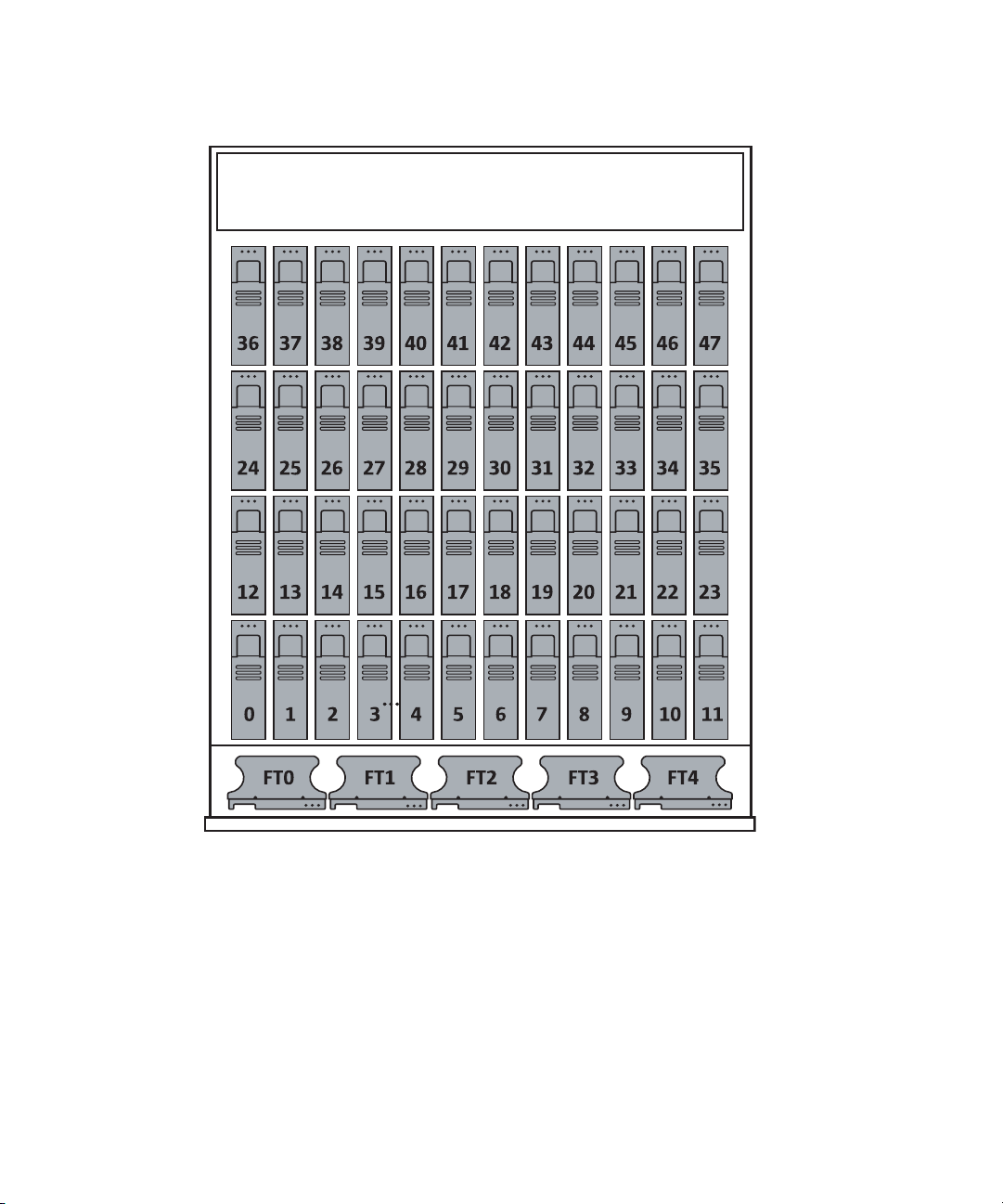
FIGURE 4-1 Disk Drive Locations
28 Sun Fire X4500/ X4540 Servers Administration Guide • October 2008

Disk Drive Status and LEDs
Each hard disk drive has a sensor that is used to communicate the state for the
slot.The hard disk drives use IPMI (Intelligent Platform Management Interface)
sensors to convey a slot state see
TABLE 4-1 Disk Drive Status Sensors
State Event Description
0 Device Not Present The drive bay is empty.
1 Device Installed The drive is detected. Used by remote management
2 Ready for Device Removal A drive is unmounted and ready to be physically
3 Device Faulted Causes the service processor to illuminate the individual
Inside the Sun Fire X4500 server chassis there are three LEDs for each of the 48 hard
disk drives: one for the Activity LED (green), one for the Fault (amber) LED and the
third for the "OK to remove" (blue) LED.
The individual LED locator can be used to control both the fault and removal LEDs
through an IPMI OEM command. The service processor handles all aspects of the
fault and removes LEDs automatically based on events in the disk drive sensors see
TABLE 4-2.
TABLE 4-1:
applications.
removed. Controls the OK to Remove LED.
disk drive fault LED.
TABLE 4-2 Disk Drive LED Indicators
LED Event Description
Green Disk drive activity Controlled by hardware. Does not require SP interaction.
Amber Hard disk drive failure Controlled by the SP over the SP-12C bus. Relies on the
operating system driver to set appropriately.
Blue Hard disk drive ready for
removal
Controlled by the SP over the SP-12C bus. The operating
system determines that the drive has been halted and is
ready to be removed.
Chapter 4 Disk Administration and Management 29

EFI Disk Label Overview
Extensible Firmware Interface (EFI) is an Intel standard used as a replacement for
the PC BIOS. It is responsible for the power-on self-test (POST) process, booting the
operating system, and providing an interface between the operating system and the
physical hardware. EFIs provides the following capabilities:
■ System-independent device drivers.
■ Delegation of networking and memory management issues to the firmware
instead of the OS.
■ EFI selection and loading of the operating system, which removes the need for a
boot loader.
Solaris 10 provides support for EFI Labels for disks that are larger than 1 terabyte on
systems that run a 64-bit Solaris kernel. The Extensible Firmware Interface GUID
Partition Table (EFI GPT) disk label provides support for physical disks and virtual
disk volumes.
You can download the EFI specification at:
http://www.intel.com/technology/efi/main_specification.htm
You can use the format -e command to apply an EFI label to a disk if the system
is running the appropriate Solaris release. However, you should review the
important information in Restrictions of the EFI Disk Label before attempting to
apply an EFI label.
For additional information about EFI disk labels, managing disks with EFI labels,
EFI disk label restrictions, and troubleshooting problems with EFI disk labels, refer
to the Solaris 10 Systems Administration Guide at:
http://docs.sun.com
30 Sun Fire X4500/ X4540 Servers Administration Guide • October 2008

Converting EFI Label to SMI (Solaris) Label On The Sun Fire X4500 Disk
To convert an EFI disk label to an SMI (Solaris) label, delete the EFI fdisk partition,
then create a new Solaris fdisk partition. Use the following steps:
Caution – Do not attempt to convert an EFI label to an SMI label using the format
(1m) command.
Chapter 4 Disk Administration and Management 31

1. Use fdisk to delete EFI fdisk.
CODE EXAMPLE 4-1 EFI to SMI Disk Label Conversion
# fdisk /dev/rdsk/c0t7d0p0
Total disk size is 30400 cylinders
Cylinder size is 16065 (512 byte) blocks
Cylinders
Partition Status Type Start End Length %
========= ====== ============ ===== === ====== ===
1 EFI 0 30400 30401 100
SELECT ONE OF THE FOLLOWING:
1. Create a partition
2. Specify the active partition
3. Delete a partition
4. Change between Solaris and Solaris2 Partition IDs
5. Exit (update disk configuration and exit)
6. Cancel (exit without updating disk configuration)
Enter Selection: 3
Specify the partition number to delete (or enter 0 to exit): 1
Are you sure you want to delete partition 1? This will make all
files and programs in this partition inaccessible (type "y" or
"n"). y
Total disk size is 30400 cylinders
Cylinder size is 16065 (512 byte) blocks
Cylinders
Partition Status Type Start End Length %
========= ====== ============ ===== === ====== ===
WARNING: no partitions are defined!
(The partition is now deleted. The menu reappears, as shown in Step 2)
32 Sun Fire X4500/ X4540 Servers Administration Guide • October 2008

2. Create the new partition.
(...continued from previous display)
SELECT ONE OF THE FOLLOWING:
1. Create a partition
2. Specify the active partition
3. Delete a partition
4. Change between Solaris and Solaris2 Partition IDs
5. Exit (update disk configuration and exit)
6. Cancel (exit without updating disk configuration)
Enter Selection: 1
Select the partition type to create:
1=SOLARIS2 2=UNIX 3=PCIXOS 4=Other
5=DOS12 6=DOS16 7=DOSEXT 8=DOSBIG
9=DOS16LBA A=x86 Boot B=Diagnostic C=FAT32
D=FAT32LBA E=DOSEXTLBA F=EFI 0=Exit?
Specify the percentage of disk to use for this partition
(or type "c" to specify the size in cylinders). 100
Should this become the active partition? If yes, it will be
activated each time the computer is reset or turned on.
Please type "y" or "n". y
Total disk size is 30400 cylinders
Cylinder size is 16065 (512 byte) blocks
Cylinders
Partition Status Type Start End Length %
========= ====== ============ ===== === ====== ===
1 Active Solaris2 1 30399 30399 100
SELECT ONE OF THE FOLLOWING:
1. Create a partition
2. Specify the active partition
3. Delete a partition
4. Change between Solaris and Solaris2 Partition IDs
5. Exit (update disk configuration and exit)
6. Cancel (exit without updating disk configuration)
Enter Selection: 5
Chapter 4 Disk Administration and Management 33

3. Verify that Solaris2 fdisk has been created on the same disk.
# fdisk /dev/rdsk/c0t7d0p0
Total disk size is 30400 cylinders
Cylinder size is 16065 (512 byte) blocks
Cylinders
Partition Status Type Start End Length %
========= ====== ============ ===== === ====== ===
1 Active Solaris2 1 30399 30399 100
SELECT ONE OF THE FOLLOWING:
1. Create a partition
2. Specify the active partition
3. Delete a partition
4. Change between Solaris and Solaris2 Partition IDs
5. Exit (update disk configuration and exit)
6. Cancel (exit without updating disk configuration)
Enter Selection: 5
The above display confirms that the Solaris2 fdisk has been created.
For additional information about converting EFI and SMI disk labels, refer to the
Solaris 10 Systems Administration Guide at:
http://docs.sun.com
Adding Disks
This assumes you have physically inserted a disk and now want to bring the
inserted disk online.
If you are replacing a mirrored bootable disk, you should use the Solaris Volume
Manager to enable the disk. For additional information, refer to the Solaris Volume
Manager Administration Guide (819-2789).
Note – You should predetermine which attachment point the disk is being inserted
into before inserting the disk. Refer to FIGURE 8-4 for a listing of disk drives.
1. Determine the attachment point by typing the following command:
# cfgadm > cfgadm_snapshot
34 Sun Fire X4500/ X4540 Servers Administration Guide • October 2008

2. Insert the disk.
3. Type the following command:
# cfgadm > cfgadm_snapshot_2
4. Compare the two files by typing the following command:
# diff cfgadm_snapshot cfgadm_snapshot_2
Information similar to the following is displayed:
29c29
< sata3/3 sata-port empty unconfigured ok
> sata3/3 disk connected unconfigured unknown
5. Remove the temporary files by typing the following command:
#
rm cfgadm_snapshot cfgadm_snapshot_2
From this information you determine that the inserted drive uses SATA port 3 on
controller 3.
6. To bring the disk online for the Solaris OS, configure the disk by typing the
following commands:
# cfgadm -c configure sata3/3
# cfgadm | grep sata3/3
The following information is displayed. For example, the disk node associated with
the disk in sata3/3 displays its logical disk node c5t3d0:
sata3/3::dsk/c5t3d0 disk connected configured ok
Note – If the blue LED does not turn on after one minute, you can have the OS
reenumerate device nodes and links by typing: # devfsadm -c.
Chapter 4 Disk Administration and Management 35

Adding a Disk to a Mirrored ZFS Configuration
The following example shows how to add another mirror to an existing mirrored
ZFS configuration on system.
# zpool status tank
pool: tank
state: ONLINE
scrub: none requested
config:
NAME STATE READ WRITE CKSUM
tank ONLINE 0 0 0
mirror ONLINE 0 0 0
c0t1d0 ONLINE 0 0 0
c1t1d0 ONLINE 0 0 0
mirror ONLINE 0 0 0
c0t2d0 ONLINE 0 0 0
c1t2d0 ONLINE 0 0 0
errors: No known data errors
# zpool add tank mirror c0t3d0 c1t3d0
# zpool status tank
pool: tank
state: ONLINE
scrub: none requested
config:
NAME STATE READ WRITE CKSUM
tank ONLINE 0 0 0
mirror ONLINE 0 0 0
c0t1d0 ONLINE 0 0 0
c1t1d0 ONLINE 0 0 0
mirror ONLINE 0 0 0
c0t2d0 ONLINE 0 0 0
c1t2d0 ONLINE 0 0 0
mirror ONLINE 0 0 0
c0t3d0 ONLINE 0 0 0
c1t3d0 ONLINE 0 0 0
errors: No known data errors
36 Sun Fire X4500/ X4540 Servers Administration Guide • October 2008

Replacing a Device in a ZFS Storage Pool
For information see “Replacing a Device in a ZFS Storage Pool” in Chapter 11, ZFS
Troubleshooting and Data Recovery of the Solaris ZFS Administration Guide.
Removing a Disk From Service
Caution – You must follow these steps before removing a disk from service. Failure
to follow the procedure can corrupt your data or render your file system inoperable.
1. Assume you know that the logical disk node is c4t0d0. Type the following
command:
# cfgadm | grep c4t0d0
The physical slot is displayed, showing where the disk is connected. For example,
this hard disk is attached to SATA controller 2, and port 0:
sata2/0::dsk/c4t0d0 disk connected configured ok
2. Unconfigure the disk before removal. To unconfigure the disk, you must
suspend activity on the SATA device. For example, type the following
command:
#
cfgadm -c unconfigure sata2/0
The system displays the following information:
unconfigure sata2/0 Unconfigure the device at:
/devices/pci@1,0/pci1022,7458@3/pci11ab,11ab@1:0
Continue (yes/no)? yes
3. Verify that the disk has been unconfigured by typing the following command:
#
cfgadm | grep sata2/0
Chapter 4 Disk Administration and Management 37

The following information shows that the disk has been unconfigured:
sata2/0 disk connected unconfigured ok
Note – The blue LEDs indicate the disks that are safe to remove.
4. Remove the disk from the chassis.
Note – If the process of unconfiguring the disk failed, the disk might be in use by
ZFS, UFS, or some other entity. See the “Correcting Unconfigure Operation Failure”
on page 38.
Correcting Unconfigure Operation Failure
This section discusses disk unconfigure operation failure.
If a disk unconfigure operation fails, check to see if the system is in the correct state,
and that a utility is not using the disk. When unconfiguring a disk that is part of a
ZFS storage pool, the following items are important:
■ Disks can be replaced or detached in a ZFS mirrored storage pool.
■ Disks can only be replaced in a ZFS RAID-Z storage pool.
For more information about detaching or replacing disks in storage pool, please refer
to the ZFS Administration Guide, (819-5461).
Unconfiguring a Disk in Use
To determine if ZFS, UFS, or another utility is using the disk, do the following:
1. Determine whether the disk is in use, by typing the following command:
# cfgadm | grep sata2/0
38 Sun Fire X4500/ X4540 Servers Administration Guide • October 2008

The following information is displayed:
sata2/0::dsk/c4t0d0 disk connected configured
ok
2. Identify if ZFS is using a disk, by typing the following command:
#
zpool status | grep c4t0d0
The following example shows that ZFS is using the disk:
c4t0d0 ONLINE 0 0 0
Note – The disk must detached from the pool or replaced with another disk before
the disk can be unconfigured. For more information about detaching or replacing
disks in a storage pool, see the ZFS Administration Guide, (819-5461).
3. To remove the disk from the ZFS pool, or to unmount that pool, type the
following command:
#
zfs unmount /spiffy_pool
Note – If the disk cannot be moved offline from the ZFS pool, then you can either
destroy or export the pool to remove the disk. See the ZFS Administration Guide,
(819-5461) for more details.
4. To stop ZFS from using the disk, type the following command:
# zpool export spiffy_pool
5. To verify that ZFS is no longer using the disk, typing the following command:
# cfgadm -c unconfigure sata2/0
The following message is displayed:
Unconfigure the device at:
/devices/pci@1,0/pci1022,7458@3/pci11ab,11ab@1:0.
This operation will suspend activity on the SATA device
Continue (yes/no)? yes
Verify that the OK to Remove blue LED is lit.
Chapter 4 Disk Administration and Management 39

6. You can now remove the hard drive.
40 Sun Fire X4500/ X4540 Servers Administration Guide • October 2008

CHAPTER
5
Sun Fire X4500 Fault Management
Architecture
This chapter includes information about the following topics:
■ “Fault Management Architecture Overview” on page 41
■ “Sun Fire X4500 Fault Management Utility Commands” on page 42
■ “Diagnosing Disk Faults” on page 44
■ “Clearing Disk Faults” on page 46
■ “Displaying Fault Statistics Using the fmstat Command” on page 47
Fault Management Architecture Overview
The Sun Fire X4500 server features the latest fault management technologies. With
the Solaris 10 Operating System (OS), the Sun Fire X4500 Server introduces a new
Fault Management Architecture (FMA) that diagnoses and predicts component
failures before they actually occur. This technology is incorporated into both the
hardware and software of the server.
At the heart of the Sun Fire X4500 server Fault Manager is the diagnosis engine. The
disk diagnosis engine receives data relating to hardware and software errors and
automatically and silently diagnoses the underlying problems. The diagnosis engine
runs in the background, silently capturing telemetry, until a diagnosis can be
completed or a fault can be predicted.
41

After processing sufficient telemetry to reach a conclusion, a diagnosis engine
produces another event called a fault event that is broadcast to any agents deployed
on the system that know how to respond. A software component known as the
Solaris Fault Manager, fmd(1M), manages the diagnosis engines and agents,
provides a simplified programming model for these clients as well as common
facilities such as event logging, and manages the multiplexing of events between
producers and consumers.
The Sun Fire X4500 Server has a Fault Management Application (FMA) that provides
fault monitoring and hotplug processing. The FMA provides passive fault
monitoring by analyzing each disk once per hour to determine if a disk fault is
imminent. If a disk fault is imminent, an FMA fault is generated and the amber Fault
LED for that disk is activated.
Sun Fire X4500 Fault Management Utility Commands
The Sun Fire X4500 server FMA obtains diagnostic information from the fault
management utilities in Solaris. The fault management commands used are:
■ “fmd Command” on page 43
■ “fmdump Command” on page 44
■ “Using thefmadm Command to Clear Faults” on page 46
■ “Displaying Fault Statistics Using the fmstat Command” on page 47
Refer to the man pages for fmd(1M), fmadm(1M), fmdump(1M), and fmstat(1M) for
more information about individual fault management utilities.
42 Sun Fire X4500/ X4540 Servers Administration Guide • October 2008

fmd Command
The Solaris OS uses the fault manager daemon, fmd(1M), which starts at boot time
and runs in the background to monitor the system. If a component generates an
error, the daemon handles the error by correlating the error with data from previous
errors and other related information to diagnose the problem.
Each problem diagnosed by the fault manager is assigned a Universal Unique
Identifier (UUID). The UUID uniquely identifies this particular problem across any
set of systems. The fmdump(1M) utility can be used to view the list of problems
diagnosed by the fault manager, along with their UUIDs and knowledge article
message identifiers. The fmadm(1M) utility can be used to view the resources on the
system believed to be faulty. The fmstat(1M) utility can be used to report statistics
kept by the fault manager. The fault manager is started automatically when Solaris
boots, so it is not necessary to use the fmd command directly.
When possible, the fault manager daemon initiates steps to self-heal the failed
component and take the component offline. The daemon also logs the fault to the
syslog daemon and provides a fault notification with a message ID (MSGID). You
can use the message ID to view additional information about the problem from
Sun’s knowledge article database at:
http://www.sun.com/msg/
For more information, refer to the fmd(1M) man page.
Chapter 5 Sun Fire X4500 Fault Management Architecture 43

fmdump Command
The fmdump command displays the list of faults detected by the FMA. You can use
this command for the following reasons:
■ To see if any faults have been detected by the FMA.
■ If you need to obtain the fault message ID (SUNW-MSG-ID) for detected faults.
■ To verify that the replacement of a FRU has cleared the fault and not generated
any additional faults.
To use the fmdump command to identify faults:
● Check the event log by typing the fmdump command with -v for verbose
output. For example:
# fmdump -v
The following is an example of displayed information. This example provides details
about the date, time and unique identifier related to the fault:
CODE EXAMPLE 5-1 fmdump Command Verbose Output
TIME UUID SUNW-MSG-ID
Jul 11 13:55:01.5548 e92f2cec-e393-cd04-89ff-c5e2081b9940 DISK8000-0X
100% fault.io.disk.predictive-failure
Problem in: hc:///:serial=VDK41BT4C7MB7S:part=HITACHIHDS7225SBSUN250G-527N7MB7S:revision=V44OA81A/motherboard=
0/hostbridge=2/pcibus=9/pcidev=8/pcifn=0/pcibus=11/pcidev=
1/pcifn=0/sata-port=1/disk=0
Affects: hc:///:serial=VDK41BT4C7MB7S/component=sata5/1
FRU: hc:///component=HD_ID_16
Diagnosing Disk Faults
To determine which disk failed, you can view the FMA fault error log, use fmdump
command, or open the system cover to look for illuminated LEDs. If you use the
fmdump command to isolate a disk, you should also open the system cover and look
for amber LEDs.
44 Sun Fire X4500/ X4540 Servers Administration Guide • October 2008

The following shows an example of the fmdump command you can use to display
disk faults.
# fmdump -v -u uuid
The following is an example of information that can display when a disk fault is
detected and the fmdump command is used:
CODE EXAMPLE 5-2 fmdump Command Diagnose Disk Fault
TIME UUID SUNW-MSG-ID
May 09 13:38:24.9404 9a2c5052-687b-e196-b12b-8035267c3031 DISK8000-0X
100% fault.io.disk.predictive-failure
Problem in: hc:///:serial=VDK41BT4C7PJYS:part=HITACHIHDS7225SBSUN250G-527N7PJYS:revision=V44OA81A/motherboard=
0/hostbridge=2/pcibus=9/pcidev=8/pcifn=0/pcibus=11/pcidev=
1/pcifn=0/sata-port=6/disk=0
Affects: hc:///component=sata5/6
FRU: hc:///component=HD_ID_29
Based on the information displayed, you can determine which disk failed and the
attachment point.
For more information, refer to the fmdump(1M) man page.
Chapter 5 Sun Fire X4500 Fault Management Architecture 45

Clearing Disk Faults
When the Solaris FMA facility detects faults, the faults are logged and displayed on
the console. After the fault condition is corrected, for example by replacing a faulty
disk, you must clear the fault.
Using thefmadm Command to Clear Faults
The fmadm command can be used to view and modify system configuration
parameters that are maintained by the Solaris Fault Manager. The fmadm fault
command is primarily used to determine the status of a component involved in a
fault. The fmadm command can be used to:
■ View the set of diagnosis engines and agents that are currently participating in
fault management.
■ View the list of system components that have been diagnosed as faulty.
■ Perform administrative tasks.
In cases, where the disk fault is cleared, some persistent fault information can
remain and result in erroneous fault messages at boot time. To ensure that these
messages are not displayed, the fmadm repair UUID command should be
performed.
To use the fmadm Command to clear faults:
● Clear faults by typing the fmadm repair command. For example:
# fmadm repair 9a2c5052-687b-e196-b12b-8035267c3031
For more information, see the fmadm(1M) man page.
46 Sun Fire X4500/ X4540 Servers Administration Guide • October 2008

Displaying Fault Statistics Using the fmstat Command
This section discusses statistics associated with the Fault Management Architecture.
The fmstat command displays statistical information about faults handled by the
FMA. The fmstat command can report statistics associated with the Solaris Fault
Manager.
In the example below, an event was received. A case is opened for that event and a
diagnosis is performed.
● Check the event log by typing the fmstat command with -v for verbose
output. For example:
# fmstat -v
The following is a example of information that may display:
CODE EXAMPLE 5-3 fmstat Command Example
module ev_recv ev_acpt wait svc_t %w %b open solve memsz bufsz
cpumem-diagnosis 0 0 0.0 0.0 0 0 0 0 3.0 K0
cpumem-retire 0 0 0.0 0.0 0 0 0 0 0 0
eft 1 1 0.0 1191.8 0 0 1 1 3.3M 11K
fmd-self-diagnosis 0 0 0.0 0.0 0 0 0 0 0 0
io-retire 1 0 0.0 32.4 0 0 0 0 37b 0
syslog-msgs 1 0 0.0 0.5 0 0 0 0 32b 0
For detailed instructions on the fmstat command, refer to the fmstat man page.
Chapter 5 Sun Fire X4500 Fault Management Architecture 47

48 Sun Fire X4500/ X4540 Servers Administration Guide • October 2008

CHAPTER
6
Rebuilding the Preinstalled OS
This chapter walks you through the steps to the Solaris Volume Manager to
manually recreate the mirrored preinstalled Solaris Operating System (OS).
For additional details about the preinstalled Solaris operating system, refer to the
Sun Fire X4500 Server Guide for Preinstalled Solaris Operating System (819-7148), and
the Sun Fire X4500 Server Installation Guide (819-4358). For additional information
about the Solaris Volume Manager, refer to the Solaris Volume Manager Administration
Guide (819-2789).
This chapter includes the following topics:
■ “Preinstalled OS Overview” on page 49
■ “Creating Preinstalled OS Disk Mirrors (RAID-1)” on page 50
■ “Recreating the Preinstalled OS” on page 52
Preinstalled OS Overview
The Solaris 10 11/06 Operating System and patches specific to the Sun Fire X4500
server are preinstalled on the hard disk drives in slot 0 and mirrored in slot 1. The
following example shows the default physical partition sizes of both disk drives.
CODE EXAMPLE 6-1 Preinstalled OS Default Partition Sizes
File System Partition Size
root Slice 0 11000 MB
swap Slice 1 2000 MB
/var Slice 5 6000 MB
metadb Slice 7 8192 blocks
49

The Sun Fire X4500 server’s preinstalled OS, file systems, and partitions are created
with RAID-1. RAID-1 creates an exact copy (or mirror) of systems data over multiple
physical disks. By duplicating the OS over separate disks, the data is protected from
disk corruption or a disk failure. Additionally, since all the data exists in multiple
copies, each with its own hardware, the read performance increases.
CODE EXAMPLE 6-2 displays the amount of disk space occupied by the preinstalled
OS file system, the amount of used and available space, and how much of the file
system’s total capacity has been used.
CODE EXAMPLE 6-2 Sun Fire X4500 Server default Preinstalled OS Partition
File System Size Used Available Capacity Mounted on
/dev/md/dsk/d10 11G 5.2G 5.3G 50% /
/devices 0K 0K 0K 0% /devices
ctfs 0K 0K 0K 0% system/contract
proc 0K 0K 0K 0% /proc
mnttab 0K 0K 0K 0% /etc/mnttab
swap 15G 656K 15G 1% /etc/system/volatile
objfs 0K 0K 0K 0% /system/object
/usr/lib/libc/ 11G 5.2G 5.3G 50% /lib/libc.so.1
libc_hwcap2.so.1
fd 0K 0K 0K 0% /dev/fd
/dev/md/dsk/d30 5.8G 1.1G 4.6G 20% /var
swap 15G 28K 15G 1% /var/run
zpool1 21T 49K 21T 1% /zpool
Creating Preinstalled OS Disk Mirrors (RAID-1)
These procedures assume that both drives are identical, that the operating system is
already installed on c5t0d0, and that the mirrored disk is c5t4d0, a typical setup for
a Sun Fire X4500 server.
Use this procedure to mirror an existing file system. If the file system can be
unmounted, the entire procedure can be completed without a reboot. For file
systems that cannot be unmounted, such as /usr and /swap, the system must be
rebooted to complete the procedure.
50 Sun Fire X4500/ X4540 Servers Administration Guide • October 2008

All RAID-1 devices must be set up by the metainit command before they can be
used. You use the metainit command to create mirrored disk partitions. The
metainit command configures metadevices, mirrors, and hot spares according to
the information specified on the command line.
metadb Command
The metadb command creates and deletes replicas of the metadevice state database.
State database replicas can be created on dedicated slices, or on slices that will later
become part of a simple metadevice.
The metadevice state database contains the configuration of all metadevices and hot
spare pools in the system. Additionally, the metadevice state database keeps track of
the current state of metadevices and hot spare pools, and their components. Solaris
Volume Manager automatically updates the metadevice state database when a
configuration or state change occurs. A submirror failure is an example of a state
change.
When creating and deleting replicas of replicas of the metadevice state database, use
the following metainit command syntax:
# metadb
where
■ -a attaches a new database device.
■ -d deletes all replicas that are located on the specified slice.
■ -f creates the initial state database.
metainit Command
When creating metadevices and mirrors, use the following metainit command
syntax:
# metainit -f volume-name number-of-stripes components-per-stripe component-
name
where
■ -f forces the command to continue. You must use this option when the slice
contains a mounted file system.
■ volume-name specifies the name of the volume to create.
■ number-of-stripes specifies the number of stripes to create.
Chapter 6 Rebuilding the Preinstalled OS 51

■ components-per-stripe specifies the number of components each stripe
should have.
■ component-names specifies the names of the components that are used.
metaroot Command
Once the mirrors are created using the metainit command, you need to remount
your newly mirrored file system, and reboot the system. To remount the file system,
use the following metaroot command syntax:
# metaroot volume-name
# init 6
For more information, see the metaroot(1M) man page.
After the file system is remounted and the system rebooted, you can attach the
second submirror. To attach the second submirror, use the following metattach
command syntax:
# metaroot volume-name submirror-name
where
■ volume-name specifies the name of the RAID-1 volume to add to the submirror
■ submirror-name specifies the name of the component that will be the second
mirror attached to the mirror.
See the metattach(1M) man page for more information.
Recreating the Preinstalled OS
To recreate the preinstalled OS, you need to perform the following procedures:
■ Mirror the root disk by:
■ Creating a metadevice from the original root, using the metainit command.
■ Creating a metadevice for the root mirror.
■ Setting up a one-way mirror of the root metadevice.
■ Configuring the system to boot the root file system from the metadevice, using
the metaroot command.
52 Sun Fire X4500/ X4540 Servers Administration Guide • October 2008

■ Attaching the second metadevice to the root metadevice to make it a two-way
mirror, using the metattach command.
■ Mirror the swap and /var partitions by:
■ Creating metadevices from the original swap and /var partitions, using the
metinit command.
■ Creating one-way mirrors of the swap and /var metadevices.
■ Mounting the new metadevices by editing the /etc/vfstab.
■ Rebooting the system.
■ Making two-way mirrors by attaching the second submirrors.
■ Configure the systems alternate boot path by:
■ Determining the path to the alternate boot device.
■ Define the alternate boot path.
■ Update the eeprom boot path value using the eeprom command.
Create a Mirror for the root (/) File System
1. Install the OS using the default configuration as a guideline.
For additional instructions on installing the Solaris OS, see the Solaris Operating
System Installation Guide (819-4362) at:
http://www.docs.sun.com.
2. Create an initial state database replica by typing the following command:
# metadb -a -f c5t0d0s7 c5t4d0s7
3. To create a mirror of the root file system:
a. Identify the slice that contains the existing root (/) file system to be
mirrored. This example uses the slices c5t0d0s0 and c5t4d0s0.
b. Create a new volume on the slice from the previous step by using the
following metainit commands:
# metainit -f d11 1 1 c5t0d0s0
d11: Concat/Stripe is setup
# metainit d12 1 1 c5t4d0s0
d12: Concat/Stripe is setup
Chapter 6 Rebuilding the Preinstalled OS 53

Create a Mirror for the swap Partition
1. To create a mirror from the /swap partition.
a. Identify the slice that contains the /swap partition to be mirrored. This
example uses the slices c5t0d0s1 and c5t4d0s1.
b. Create a new volume on the slice from the previous step by using the
following metainit commands:
# metainit -f d21 1 1 c5t0d0s1
d21: Concat/Stripe is setup
# metainit d22 1 1 c5t4d0s1
d22: Concat/Stripe is setup
If there is an entry for swap in the /etc/vfstab file, it must be edited to
reference the mirror.
Create a Mirror for the /var Partition
1. To create a mirror from the /var partition.
a. Identify the slice that contains the /var partition to be mirrored. This
example uses the slices c5t0d0s5 and c5t4d0s5.
b. Create a new volume on the slice from the previous step by using the
following metainit command:
# metainit -f d31 1 1 c5t0d0s5
d31: Concat/Stripe is setup
# metainit d32 1 1 c5t4d0s5
d32: Concat/Stripe is setup
54 Sun Fire X4500/ X4540 Servers Administration Guide • October 2008

Create / root, /swap, and /var Mirrors
● Create the mirrors by typing the following command:
# metainit d10 -m d11
d10: Mirror is setup
# metainit d20 -m d21
d20: Mirror is setup
# metainit d30 -m d31
d30: Mirror is setup
2. Remount the file system by typing the following command:
# metaroot d10
For more information, see the metaroot(1M) man page.
3. Edit the /etc/vfstab file so that root, swap, and /var is appropriately
referenced.
4. Reboot the server by entering the following command:
# init 6
Attach / root, /swap, and /var Mirrors
● Attach the mirrors by typing the following command:
# metattach d10 d12
d10: submirror d12 is attached
# metattach d20 d22
d20: submirror d22 is attached
# metattach d30 d32
d30: submirror d32 is attached
Refer to the metattach(1M) man page for more information.
Chapter 6 Rebuilding the Preinstalled OS 55

Display Current Status of the Metadevices
The metastat command displays the current status for each metadevice (including
stripes, concatenations, concatenations of stripes, mirrors, specified metadevices,
and components.
● Display the Metadevices by typing the following command:
# metastat -c
d30 m 5.9GB d31 d32
d31 s 5.9GB c5t0d0s5
d32 s 5.9GB c5t4d0s5
d20 m 2.0GB d21 d22
d21 s 2.0GB c5t0d0s1
d22 s 2.0GB c5t4d0s1
d10 m 10GB d11 d12
d11 s 10GB c5t0d0s0
d12 s 10GB c5t4d0s0
Install GRUB on the Boot Disk
GRUB stands for GRand Unified Bootloader. It installs GRUB stage 1 and stage 2
files on the boot area of a disk partition.
1. Install GRUB by typing the following command.
# /sbin/installgrub -fm /boot/grub/stage1 /boot/grub/stage2
/dev/rdsk/c5t4d0s0
stage1 written to partition 0 sector 0 (abs 16065)
stage2 written to partition 0, 233 sectors starting at 50
(abs 16115)
stage1 written to master boot sector
56 Sun Fire X4500/ X4540 Servers Administration Guide • October 2008

Configure the Alternate Boot Device
1. Record the alternate boot path.
Configure your system so that if your primary submirror fails, the system boots from
the secondary submirror. To enable the system to boot from the disk that holds the
secondary submirror, configure the system to see the disk as the alternate boot
device.
a. Determine the path to the alternate boot device. For example:
# ls -l /dev/dsk/c5t4d0s0
b. Record the string.
Note – Because the system might not be available, you should write down this
information in a different location than on the system.
c. Use the eeprom command to define the alternative boot path. For example:
# eeprom altbootpath
/pci@1,0/pci1022,7458@4/pci11ab,11ab@1/disk@4,0:a
For more information about using the eeprom command, refer to the eeprom man
page.
Chapter 6 Rebuilding the Preinstalled OS 57

58 Sun Fire X4500/ X4540 Servers Administration Guide • October 2008

CHAPTER
7
Using Disk Control and Monitor Utility (DCMU)
This chapter describes how to use the Disk Control and Monitor Utility (DCMU). It
includes the following sections:
■ “Overview of the Disk Control and Monitor Utility” on page 59
■ “Using DCMU” on page 60
Overview of the Disk Control and Monitor Utility
The Disk Control and Monitor Utility (DCMU) is a utility designed for Sun Fire
X4500 server that runs the Red Hat Enterprise Linux U4 64-bit operating system.
The DCMU controls and monitors all 48-disk drives and slots on the Sun Fire X4500
server and provides the following features:
■ Monitors and reports hotplug events to service processor (SP)
■ Reports disk drive failures to the service processor
■ Manages disk drives and reports required actions to the SP
■ Reports disk drive field replaceable unit (FRU) information to the SP
The DCMU consist of three components. Each component updates the service
processor:
■ cfgdisk
■ hotplugmon
■ faultmond
59

Using DCMU
To use DCMU, you must install the application.
cfgdisk Command
cfgdisk is a command-line utility and that queries and provides status of all
48-disk drives. cfgdisk also allows you to connect and disconnect disk drives.
cfgdisk Command Options
Use the cfgdisk command to determine the disk drive status by using the
parameters shown in
functions shown:
TABLE 7-1 cfgdisk Command Options
Option Description
-h Displays help information
-v Displays utility version information
-o Displays operation information <connect/disconnect>
-d Displays disk drive information
TABLE 7-1. The following options are supported for the
Examples Using the cfgdisk Command
The following command shows the use of cfgdisk to disconnect a disk drive.
TABLE 7-2
# cfgdisk -o disconnect -d sata0/7
Device sata0/7 has been successfully disconnected
The following command shows the use of cfgdisk to connect a disk drive
TABLE 7-3
# cfgdisk -o connect -d sata0/7
Command has been issued to connect sata0/7 device, it may take few
seconds to connect sata0/7,
60 Sun Fire X4500/ X4540 Servers Administration Guide • October 2008

Use the cfgdisk command to display the status after disconnecting a disk drive:
TABLE 7-4
# cfgdisk
hotplugmon
The hotplugmon utility monitors disk drive hotplug events and then reports them to
service processor. hotplugmon is not a command line utility. To verify a hotplug
event, you should check the corresponding entry in service processor log using
following ipmitool commands on the server:
TABLE 7-5
# ipmitool -I open sdr elist
Or from another server type:
TABLE 7-6
# ipmitool -I lan -H SP-IP -U root -P changeme sdr elist
faultmond Command
faultmond is a daemon that is started at boot time. It scans for faulted disk,
pending disk failures, and FRU information.
Use the faultmond command to determine faulted disk drives by using the
parameters shown in
functions shown:
TABLE 7-7 faultmond Command Options
Option Description
-h Displays help information
-t Displays polling information <minutes>
-v Displays version information
-D Runs as a non-daemon process
TABLE 7-7. The following options are supported for the
Chapter 7 Using Disk Control and Monitor Utility (DCMU) 61

Examples Using the faultmond Command
The following command shows the use of faultmond:
TABLE 7-8
# faultmond -h
faultmond version 1.0
The following command shows the use of faultmond running as a non-daemon:
TABLE 7-9
# faultmond -D -t 5
The following commands can be used to faultmond from the command-line:
TABLE 7-10
# service faultmond start
# service ipmi start
For additional information about cfgdisk, hotplugmon,orfaultmond, refer to
the man pages for cfgdisk (1M), hotplugmon (1M), and faultmon(1M).
62 Sun Fire X4500/ X4540 Servers Administration Guide • October 2008

PA R T
II Sun Fire X4540 Server Administration
Guide
This part contains the Sun Fire X4540 Server Administration Guide and has the
following chapters:
■ Chapter 8 provides an introduction to the Sun Fire X4540 server information.
■ Chapter 9 provides system and operating environment information.
■ Chapter 10 provides information on how to identify and configure components.
■ Chapter 11 provides hard disk management information.
■ Chapter 13 provides disk administration and management information.
■ Chapter 12 provides fault management architecture information.
■ Chapter 13 provides information about how to rebuild the preinstalled OS.


CHAPTER
8
Introduction to the Sun Fire X4540 Server
This chapter introduces you to the Sun Fire X4540 Server and describes important
features.
The following information is covered in this chapter:
■ “X4540 Server Features” on page 65
■ “Exterior Features, Controls, and Indicators” on page 67
■ “About Reliability, Availability, and Serviceability Features” on page 74
X4540 Server Features
The Sun Fire X4540 server is a mid-level, modular, rack-optimized server in the Sun
x64 product family. The family platform includes servers engineered for AMD
Opteron CPUs. The Sun Fire X4540 server deploys into commercial server markets in
a slide-mounted, horizontally-biased enclosure for rack cabinet installations,
primarily in datacenter locations.
The Sun Fire X4540 server includes an extensive set of reliability, availability, and
serviceability (RAS) features, such as hot-pluggable and redundant hard disk drives
(when RAID 1 is used), and hot-swappable fans, and power supplies. The servers
also provide an integrated lights out management (ILOM) service processor function
that includes remote boot and remote software upgrades.
TABLE 8-1 summarizes the features of the Sun Fire X4540 server.
65

TABLE 8-1 Summary of X4540 Server Features
Feature or
Component Sun Fire X4540 Server
CPU Two AMD Opteron 2000 Series CPUs, Quad-Core, 2-socket
configuration
Processor BIOS 8-Mb Flash with LPC interface.
Memory 16 DIMM slots (8 per processor), up to 4 GB per DIMM (64 GB per
system). 128-bit DDR2 interface (2x64-bit data+2x8-bit ECC)
Hard disk drives
(HDDs)
Up to forty-eight 3.5 SATA drives, of 250/500/750GB/1TB capacity
each (over 48 TB total system capacity), supports SATA II, 3.0Gb/s.
Service Processor Integrated Lights Out Manager (ILOM).
Refer to the ILOM documentation (see the Integrated Lights Out
Manager (ILOM) Administration Guide (819-0280).
RAID options RAID is configured through software.
Network I/O • Four 10/100/1000BASE-T Gigabit Ethernet ports (RJ-45 connectors)
• One 10/100BASE-T Ethernet net management port (RJ-45
Connector) NET MGT
• One RS-232 serial port (RJ-45 Connector) SER MGT (see Serial Port)
Serial Port RS-232 serial interface, RJ45 connector
Console only, no modem support (no RI, PPP)
Connected to ILOM by default
Default parameters
• 9600 baud
• 8 data bits
• No parity
• 1 stop bit
• No flow control
PCI I/O Three PCI-e slots, 8-laneslot (x8), LSI SAS 1068E.
• Six SATA Controllers on IO Board, LSI SATA controller x 6. Each
controller supports 8 HDDs
• 51.5 mm (2.5 inches) maximum height
• 169.3 mm (6.7 inches) maximum length
66 Sun Fire X4500/ X4540 Servers Administration Guide • October 2008

TABLE 8-1 Summary of X4540 Server Features
Feature or
Component Sun Fire X4540 Server
Other I/O • Four USB 2.0 ports
• One VGA video port
• Compact flash card slot
Power 1500 W DC max output per power supply, two bays, 1+1 redundancy,
hot-swappable.
1130 W AC max system input power = 3856 BTU/hr = 0.321 tons of air
conditioning, 200–240 VAC.
Fans Five fan modules; also additional fans in each power supply.
Cooling is front-to-back forced air. Hot swappable, Variable speed,
7500 R.P.M. max, Top loading, Fault/OK LEDs,1.8A / 18W, SATA
connector.
The SP software controls the fan speed and detects fan failure.
Operation terminates if a fan tray is removed.
NOTE: Do not operate the system with a fan removed for more than 60
seconds.
Exterior Features, Controls, and Indicators
This section describes the features, controls, and indicators on the front and rear
panels of the Sun Fire X4540 server.
Front Panel
FIGURE 8-1 shows the front panel. FIGURE 8-2 shows a close up of the controls and
indicators.
Chapter 8 Introduction to the Sun Fire X4540 Server 67

FIGURE 8-1 Sun Fire X4540 Server Front Panel Features
USB connectors
FIGURE 8-2 Sun Fire X4540 Server Front Panel Controls and Indicators
(1)
Serial number labels on ledge
(2) (3) (4)
(5) (6)
(7)
(1)
68 Sun Fire X4500/ X4540 Servers Administration Guide • October 2008

TABLE 8-2 Sun Fire X4540 Server Front Panel Controls and Indicators
Number Name Color Description
1 Locate button/LED White Operators can turn this LED on remotely
to help them locate the server in a
crowded server room. Press to turn off.
2 Service action required Amber On - When service action is required.
3 Power/Operation Green Steady - Power is on.
Blink - Standby power is on but main
power is off.
Off - Power is off.
4 System power button Gray To power on main power for all the
server components.
5 Top failure LED Amber On - HDD or fan fault.
6 Rear failure LED Amber On - Power supply or system controller
fault (service is required).
7 Over temperature LED Amber On - When system is over temperature.
FIGURE 8-3 shows the rear panel features.
FIGURE 8-3 Sun Fire X4540 Server Rear Panel
Chapter 8 Introduction to the Sun Fire X4540 Server 69

(1)
(2)
(3)
(4) (5)(6) (8)
TABLE 8-3 Rear Panel Features
# Name Description
(7) (10)(9) (12)(11) (14)(13)
1 AC power connectors Verify that the PS LEDs are green. Each power supply has its
own AC connector with a clip to secure its power cable.
2 Chassis ground Connect grounding straps here.
3 0 PCI-e, 1 PCI-e, 2
Slots for three PCI-e cards.
PCI-e
4 Locate button/LED White Operators can turn this LED On remotely to help then
locate the server in a crowded server room. Press to turn off.
5 Fault LED Amber – When on, service action required.
Steady – Power is On.
Off – Power is Off.
6 OK LED Green – Service action allowed.
When On, service action is required.
Blink – Standby power is On but main power is Off.
70 Sun Fire X4500/ X4540 Servers Administration Guide • October 2008

TABLE 8-3 Rear Panel Features (Continued)
# Name Description
7 SVC Service buttons SP – Reset Service Processor.
NMI – Non-Maskable Interrupt dump. Sends an NMI to the
CPU. Used for debugging only.
Host – Reset Host Bus Adapter.
Do not use these buttons unless instructed by Sun service
personnel. To operate these buttons, insert a stylus or a
straightened paper clip into the recess.
8 SC - System controller
status LEDs
9 SER MGT Serial management port (serial connection to service
10 NET MGT (S) Net management and service processor port.
11 10/100/1000 GigabitEthernet ports connect server to Ethernet.
12 USB connectors Connect USB devices.
13 Video connector Connect video monitor.
14 Compact flash (CF)
card
Blue – Ready to remove.
Amber – Fault, service action required.
Green – Operational, no action required.
processor).
Insert compact flash card devices.
Disk Drive and Fan Tray LEDs
FIGURE 8-4 shows the location of the internal LEDs.
FIGURE 8-5 shows a close-up view of the disk drive and fan trays, including the
symbols that identify the LEDs.
Chapter 8 Introduction to the Sun Fire X4540 Server 71

FIGURE 8-4 Disk Drive Locations
72 Sun Fire X4500/ X4540 Servers Administration Guide • October 2008

FIGURE 8-5 Disk Drive and Fan Tray LEDs
Note - The fan can be removed at
any time. Ignore the Fan Ready to
Remove LED.
Chapter 8 Introduction to the Sun Fire X4540 Server 73

About Reliability, Availability, and Serviceability Features
Reliability, availability, and serviceability (RAS) are aspects of a system’s design that
affect its ability to operate continuously and to minimize the time necessary to
service the system. Together, reliability, availability, and serviceability features
provide for near continuous system operation.
Reliability refers to a system’s ability to operate continuously without failures and to
maintain data integrity. System availability refers to the percentage of time that a
system remains accessible and usable. Serviceability relates to the time it takes to
restore a system to service following a system failure.
To deliver high levels of reliability, availability and serviceability, the Sun Fire X4540
Server system offers the following features:
■ Hot-pluggable disk drives
■ Redundant, hot-swappable power supplies
■ Environmental monitoring and fault protection
■ Integrated Lights Out Management (ILOM), Sun’s remote management capability
■ Support for disk and network multipathing with automatic failover capability
■ Error correction and parity checking for improved data integrity
■ Easy access to all internal replaceable components
■ Full in-rack serviceability by extending the slides
Hot-Pluggable and Hot-Swappable Components
Sun Fire X4540 Server hardware is designed to support hot-pluggable and
hot-swappable components. Hot-plugging and hot-swapping are cost-effective
solutions that provides increased system availability and continuous serviceability
for business-critical computing environments, by providing the ability to:
■ Remove or replace a failed or failing component while the system is operating
without service disruption.
■ Increase storage capacity dynamically to handle larger work loads and improve
system performance.
74 Sun Fire X4500/ X4540 Servers Administration Guide • October 2008

Hot-pluggable Components Overview
The Sun Fire X4540 server hot-plug technology allows a component to be added,
upgraded, or replaced while the system is running without affecting hardware
integrity.
Hot-plugging provides the ability to physically add, remove, or replace a hard disk
drive while the system is running, and other hard disks in the system provide
continuous service. When a hot-pluggable component is removed from the Sun Fire
X4540 server, it must be taken offline from the operating system first, but does not
require that the server be powered off.
On the Sun Fire X4540 server, you can hot-plug the following components.
TABLE 8-4 Sun Fire X4540 Hot-Pluggable Devices
Component Part Number
250 GB SATA 3.5 Hard Disk Drive 541-1467
500 GB SATA 3.5 Hard Disk Drive 541-1468
750 GB SATA 3.5 Hard Disk Drive 540-7244
1 TB SATA 3.5 Hard Disk Drive 540-7507
For instructions on hot-plugging components, see the following:
■ cfgadm Command in “cfgadm Command” on page 85.
■ cfgadm(1M) (See the cfgadm(1M) man page for more information.)
Hot-swappable Components Overview
A hot-swappable component can be removed or replaced without affecting software
integrity. A component that is removed does not need to be taken offline from the
operating system first.
On the Sun Fire X4540 server, you can hot-swap the following components:
TABLE 8-5 Sun Fire X4540 Hot-Swappable Devices (Partial List)
Component Part Number
Power supply (type A205) 300-1787
Fan module 541-0458
Chapter 8 Introduction to the Sun Fire X4540 Server 75

For more information about updating the Sun Fire X4540 Server, product updates, or
for the most up-to-date list of replaceable components, refer to the Sun Fire X4540
Server Service Manual (819-4359), and the Sun Fire X4540 Server Product Notes (820-
4869).
76 Sun Fire X4500/ X4540 Servers Administration Guide • October 2008

CHAPTER
9
Software and Operating Environment
The Sun Fire X4540 server supports Solaris 32-bit and 64-bit operating systems. The
server is shipped with Integrated Lights Out Manager (ILOM) and Solaris 10 4/08
operating system which includes the newly designed Solaris ZFS File System
(Zettabyte File System).
This chapter includes the following topics:
■ “About ZFS” on page 77
■ “About Integrated Lights Out Manager (ILOM)” on page 79
■ “About Intelligent Platform Management (IPMI)” on page 80
About ZFS
This section includes the following topics:
■ “Overview” on page 78
■ “Devices” on page 78
■ “Structure” on page 78
■ “Using the ZFS File System” on page 79
■ “Additional information” on page 79
77

Overview
ZFS is a 128-bit file system that provides 16 billion times the capacity of 32-bit or
even 64-bit file systems. With ZFS, data is protected by 64-bit checksums to provide
error detection and correction functionally. It constantly reads and checks data to
ensure that it is correct. If it detects an error in a mirrored pool, the technology
automatically repairs the corrupted data. ZFS is available in the Solaris 10 4/08 OS.
The ZFS ( Zettabyte File System) system delivers file system management
capabilities by automating common administrative tasks, protecting data from
corruption and providing virtually unlimited scalability.
Devices
Because ZFS file systems are not constrained to specific devices, they can be created
easily and quickly, similar to the way directories are created. ZFS file systems grow
automatically within the space allocated to the storage pool.
Historically, file systems have been constrained to one device so that the file systems
themselves have been constrained to the size of the device. Creating and re-creating
traditional file systems because of size constraints are time-consuming and
sometimes difficult. Traditional volume management products helped manage this
process.
Structure
ZFS uses virtual storage pools to make it easy to expand or contract file systems
simply by adding more drives. Instead of creating one file system, such as
/export/home, to manage many user subdirectories, you can create one file system
per user. In addition, ZFS provides a file system hierarchy so that you can easily set
up and manage many file systems by applying properties that can be inherited by
file systems contained within the hierarchy.
ZFS is a lightweight POSIX file system that is built on top of a storage pool. File
systems can be dynamically created and destroyed without requiring you to allocate
or format any underlying space. Because file systems are so lightweight and because
they are the central point of administration in ZFS, you are likely to create many of
them.
78 Sun Fire X4500/ X4540 Servers Administration Guide • October 2008

Using the ZFS File System
This section describes how to use the Solaris ZFS File System (Zettabyte File System)
on the Sun Fire X4540 server.
You administer ZFS file systems by using the zfs command. This command
provides a set of subcommands that perform specific operations on file systems. You
can also manage snapshots, volumes, and clones by using this command, but these
features are covered only briefly in this chapter.
With ZFS you can perform the following administrative functions:
■ Manage devices.
■ Create file systems.
■ Create and manage storage pools.
■ Create and manage volumes.
■ Take a snapshot of a file system or volume.
Additional information
For information on best practices for the ZFS File System see:
http://www.solarisinternals.com/wiki/index.php/ZFS_Best_Practices_Guide
For more information about ZFS, and for an example of creating a file system, refer
to the ZFS Administration Guide, (819-5461). General concepts such as hierarchical file
system layout, property inheritance, and automatic mount point management and
share interactions are included in the ZFS Administration Guide.
About Integrated Lights Out Manager (ILOM)
(ILOM) Integrated Lights Out Manager is an Intelligent Platform Management
Interface (IPMI) 2.0-compliant Baseboard Management Controller (BMC) that
implements Lights Out Management (LOM), including Remote Keyboard, Video,
Mouse, and Storage (RKVMS); a web management interface; a command-line
interface (CLI); and Simple Network Management Protocol (SNMP).
The ILOM software includes the following:
■ Embedded, hardened Linux OS
Chapter 9 Software and Operating Environment 79

■ IPMI 2.0 BMC
■ Platform Control agents diagnostics software
■ RKVMS
Lights Out Management is performed on the Sun Fire X4540 server through
IPMItool, a command-line utility for controlling IPMI-enabled devices. For more
information about Integrated Lights Out Manager (ILOM, refer to the Integrated
Lights Out Manager (ILOM) Administration Guide, (819-1160).
About Intelligent Platform Management (IPMI)
Intelligent Platform Management (IPMI) refers to the autonomous monitoring,
logging, recovery, and inventory control features implemented in hardware and
firmware.
There are two major components of platform management: the Service Processor (SP
or BMC) and the System Management Software (SMS). Platform status information
can be obtained and recovery actions initiated under situations in which system
management software and normal in-band management mechanisms are
unavailable.
SNMP (Simple Network Management Protocol) is a network management protocol
used almost exclusively in TCP/IP networks. It provides remote access by
SNMP-compliant entities to monitor and control network devices and to manage
configurations, statistics collection, performance, and security on a network.
IPMI messages can be used to communicate with the SP BMC over serial and LAN
interfaces, so software designed for in-band (local) management can be re-used for
out-of-band (remote) management simply by changing the low-level
communications layer.
The IPMItool is a simple command-line interface to systems that support the IPMI
v2.0 specification. IPMItool provides the ability to read the sensor data repository
and print sensor values, display the contents of the system event log, and SNMP.
Refer to the Sun Fire X4540 Server ILOM Supplement and Sun Fire X4540 server
Diagnostics Guide for additional information about IPMI.
80 Sun Fire X4500/ X4540 Servers Administration Guide • October 2008

CHAPTER
10
Identifying and Configuring Components
This chapter introduces the tools that let you administer the Sun Fire X4540 server
and explains how the tools work together.
Topics in this chapter include:
■ “Solaris System Commands” on page 81
■ “Component Configuration Information” on page 89
For detailed instructions on diagnosing the server, refer to the Sun Fire X4540 Server
Diagnostics Guide (819-4363) and the Sun Fire X4540 Server Service Manual (819-4359).
The Sun Fire X4540 server and its accompanying software contain tools and features
that help you:
■ Isolate problems when there is a failure of a field-replaceable component
■ Monitor the status of a functioning system
■ Exercise the system to disclose an intermittent or incipient problem
Solaris System Commands
This section describes Solaris superuser commands that you can use to assess Sun
Fire X4540 server condition and troubleshoot server problems. The related
commands include:
■ “prtconf Command” on page 82 displays the Solaris device tree.
■ “prtdiag Command” on page 83 summarizes system component status.
■ “psrinfo Command” on page 84 displays online CPU date and time.
■ “showrev Command” on page 85 displays revision information.
81

■ “cfgadm Command” on page 85 takes a component offline.
For additional information about these commands, see the command man pages.
prtconf Command
The prtconf command displays the Solaris device tree. This tree includes all the
devices probed by the firmware, as well as additional devices, like individual disks,
that only the operating environment software can detect. The output of prtconf
also includes the total amount of system memory.
CODE EXAMPLE 10-1 prtconf Command Output
$ /usr/sbin/prtconf -p
System Configuration: Sun Microsystems i86pc
Memory size: 32768 Megabytes
System Peripherals (PROM Nodes):
Node ’i86pc’
Node ’ramdisk’
Node ’isa’
Node ’pci’
Node ’pci10de,cb84’
Node ’pci10de,cb84’
The prtconf command’s -p option produces output similar to the show-devs
command. The show-devs command lists only those devices compiled by the
system firmware.
82 Sun Fire X4500/ X4540 Servers Administration Guide • October 2008

prtdiag Command
The prtdiag command summarizes system component status in table format.
CODE EXAMPLE 10-2 prtdiag Command Output
$ /usr/sbin/prtdiag
System Configuration: Sun Microsystems Sun Fire X4540
BIOS Configuration: American Megatrends Inc. 080014 04/04/2008
BMC Configuration: IPMI 2.0 (KCS: Keyboard Controller Style)
==== Processor Sockets ====================================
Version Location Tag
-------------------------------- -------------------------Quad-Core AMD Opteron(tm) Processor 2356 CPU 1
Quad-Core AMD Opteron(tm) Processor 2356 CPU 2
==== Memory Device Sockets ================================
Type Status Set Device Locator Bank Locator
------- ------ --- ------------------- -------------------DDR2 in use 0 DIMM0 BANK0
DDR2 in use 0 DIMM1 BANK1
...
DDR2 in use 0 DIMM15 BANK15
==== On-Board Devices =====================================
Gigabit Ethernet #0
Gigabit Ethernet #1
Gigabit Ethernet #2
Gigabit Ethernet #3
AST2000 VGA
LSI SCSI 1068-e #0
LSI SCSI 1068-e #1
LSI SCSI 1068-e #2
LSI SCSI 1068-e #3
LSI SCSI 1068-e #4
LSI SCSI 1068-e #5
==== Upgradeable Slots ====================================
ID Status Type Description
--- --------- ---------------- ---------------------------1 available PCI Express PCIExp SLOT0
2 available PCI Express PCIExp SLOT1
3 available PCI Express PCIExp SLOT2
Chapter 10 Identifying and Configuring Components 83

psrinfo Command
The psrinfo command displays the date and time each CPU came online. With the
verbose (-v) option, the command displays additional information about the CPUs,
including their clock speed. The following is sample output from the psrinfo
command with the -v option.
CODE EXAMPLE 10-3 psrinfo -v Command Output
$ /usr/sbin/psrinfo -v
Status of virtual processor 0 as of: 06/25/2008 17:54:39
on-line since 06/25/2008 11:34:12.
The i386 processor operates at 2300 MHz,
and has an i387 compatible floating point processor.
Status of virtual processor 1 as of: 06/25/2008 17:54:39
on-line since 06/25/2008 11:34:16.
The i386 processor operates at 2300 MHz,
and has an i387 compatible floating point processor.
Status of virtual processor 2 as of: 06/25/2008 17:54:39
on-line since 06/25/2008 11:34:18.
The i386 processor operates at 2300 MHz,
and has an i387 compatible floating point processor.
Status of virtual processor 3 as of: 06/25/2008 17:54:39
on-line since 06/25/2008 11:34:20.
The i386 processor operates at 2300 MHz,
and has an i387 compatible floating point processor.
Status of virtual processor 4 as of: 06/25/2008 17:54:39
on-line since 06/25/2008 11:34:22.
The i386 processor operates at 2300 MHz,
and has an i387 compatible floating point processor.
Status of virtual processor 5 as of: 06/25/2008 17:54:39
on-line since 06/25/2008 11:34:24.
The i386 processor operates at 2300 MHz,
and has an i387 compatible floating point processor.
Status of virtual processor 6 as of: 06/25/2008 17:54:39
on-line since 06/25/2008 11:34:26.
The i386 processor operates at 2300 MHz,
and has an i387 compatible floating point processor.
Status of virtual processor 7 as of: 06/25/2008 17:54:39
on-line since 06/25/2008 11:34:28.
The i386 processor operates at 2300 MHz,
and has an i387 compatible floating point processor.
84 Sun Fire X4500/ X4540 Servers Administration Guide • October 2008

showrev Command
The showrev command displays revision information for hardware and software.
Code example 3-4 shows sample output of the showrev command.
CODE EXAMPLE 10-4 showrev Command Output
$ showrev
Hostname: abc-123
Hostid: dbc23b9
Release: 5.10
Kernel architecture: i86pc
Application architecture: i386
Hardware provider:
Domain:
Kernel version: SunOS 5.10 Generic_127128-11
cfgadm Command
The cfgadm command is used to take a component offline. The benefit of using the
cfgadm command is that you can add, remove, or replace components while the
system is running. An added benefit is that the cfgadm command guides you
through the steps needed to add, remove, or replace system components.
The cfgadm command resides in the /usr/sbin directory. (See the cfgadm(1M)
man page for more information.)
Features of the cfgadm command include the following:
■ Displaying system component status
■ Testing system components
■ Changing component configurations
■ Displaying configuration help messages
Chapter 10 Identifying and Configuring Components 85

CODE EXAMPLE 10-5 cfgadm Command Output
$ /usr/sbin/cfgadm
Ap_Id Type Receptacle Occupant
Condition
c0 scsi-bus connected configured unknown
c1 scsi-bus connected configured unknown
c2 scsi-bus connected configured unknown
c3 scsi-bus connected configured unknown
c4 scsi-bus connected configured unknown
c5 scsi-bus connected configured unknown
usb0/1 unknown empty unconfigured ok
usb0/2 unknown empty unconfigured ok
usb0/3 unknown empty unconfigured ok
usb0/4 unknown empty unconfigured ok
usb0/5 usb-device connected configured ok
usb0/6 unknown empty unconfigured ok
usb0/7 unknown empty unconfigured ok
usb0/8 unknown empty unconfigured ok
usb0/9 unknown empty unconfigured ok
usb0/10 unknown empty unconfigured ok
usb1/1 unknown empty unconfigured ok
usb1/2 unknown empty unconfigured ok
usb1/3 unknown empty unconfigured ok
usb1/4 unknown empty unconfigured ok
usb1/5 unknown empty unconfigured ok
usb1/6 usb-hub connected configured ok
usb1/6.1 unknown empty unconfigured ok
usb1/6.2 unknown empty unconfigured ok
usb1/6.3 unknown empty unconfigured ok
usb1/6.4 unknown empty unconfigured ok
usb1/7 unknown empty unconfigured ok
usb1/8 unknown empty unconfigured ok
usb1/9 unknown empty unconfigured ok
usb1/10 unknown empty unconfigured ok
You can use the cfgadm -al (1M) command to display device type, configuration,
and condition status information about drives.
86 Sun Fire X4500/ X4540 Servers Administration Guide • October 2008
 Loading...