

Page 1

Sun Fire™ V890 Server
Service Manual
Sun Microsystems, Inc.
www.sun.com
Part No. 817-3957-12
October 2005 Revision A
Submit comments about this document at: http://www.sun.com/hwdocs/feedback
Page 2

Copyright 2005 Sun Microsystems, Inc., 4150 Network Circle, Santa Clara, California 95054, U.S.A. All rights reserved.
Sun Microsystems, Inc. has intellectual property rights relating to technology that is described in this document. In particular, and without
limitation, these intellectual property rights may include one or more of the U.S. patents listed at http://www.sun.com/patents and one or
more additional patents or pending patent applications in the U.S. and in other countries.
This document and the product to which it pertains are distributed under licenses restricting their use, copying, distribution, and
decompilation. No part of the product or of this document may be reproduced in any form by any means without prior written authorization of
Sun and its licensors, if any.
Third-party software, including font technology, is copyrighted and licensed from Sun suppliers.
Parts of the product may be derived from Berkeley BSD systems, licensed from the University of California. UNIX is a registered trademark in
the U.S. and in other countries, exclusively licensed through X/Open Company, Ltd.
Sun, Sun Microsystems, the Sun logo, AnswerBook2, docs.sun.com, Sun Fire, OpenBoot, Sun StorEdge, UltraSPARC, VIS, SunSolve Online,
and Solaris are trademarks or registered trademarks of Sun Microsystems, Inc. in the U.S. and in other countries.
All SPARC trademarks are used under license and are trademarks or registered trademarks of SPARC International, Inc. in the U.S. and in other
countries. Products bearing SPARC trademarks are based upon an architecture developed by Sun Microsystems, Inc.
The OPEN LOOK and Sun™ Graphical User Interface was developed by Sun Microsystems, Inc. for its users and licensees. Sun acknowledges
the pioneering efforts of Xerox in researching and developing the concept of visual or graphical user interfaces for the computer industry. Sun
holds a non-exclusive license from Xerox to the Xerox Graphical User Interface, which license also covers Sun’s licensees who implement OPEN
LOOK GUIs and otherwise comply with Sun’s written license agreements.
U.S. Government Rights—Commercial use. Government users are subject to the Sun Microsystems, Inc. standard license agreement and
applicable provisions of the FAR and its supplements.
DOCUMENTATION IS PROVIDED "AS IS" AND ALL EXPRESS OR IMPLIED CONDITIONS, REPRESENTATIONS AND WARRANTIES,
INCLUDING ANY IMPLIED WARRANTY OF MERCHANTABILITY, FITNESS FOR A PARTICULAR PURPOSE OR NON-INFRINGEMENT,
ARE DISCLAIMED, EXCEPT TO THE EXTENT THAT SUCH DISCLAIMERS ARE HELD TO BE LEGALLY INVALID.
Copyright 2005 Sun Microsystems, Inc., 4150 Network Circle, Santa Clara, Californie 95054, Etats-Unis. Tous droits réservés.
Sun Microsystems, Inc. a les droits de propriété intellectuels relatants à la technologie qui est décrit dans ce document. En particulier, et sans la
limitation, ces droits de propriété intellectuels peuvent inclure un ou plus des brevets américains énumérés à http://www.sun.com/patents et
un ou les brevets plus supplémentaires ou les applications de brevet en attente dans les Etats-Unis et dans les autres pays.
Ce produit ou document est protégé par un copyright et distribué avec des licences qui en restreignent l’utilisation, la copie, la distribution, et la
décompilation. Aucune partie de ce produit ou document ne peut être reproduite sous aucune forme, par quelque moyen que ce soit, sans
l’autorisation préalable et écrite de Sun et de ses bailleurs de licence, s’il y en a.
Le logiciel détenu par des tiers, et qui comprend la technologie relative aux polices de caractères, est protégé par un copyright et licencié par des
fournisseurs de Sun.
Des parties de ce produit pourront être dérivées des systèmes Berkeley BSD licenciés par l’Université de Californie. UNIX est une marque
déposée aux Etats-Unis et dans d’autres pays et licenciée exclusivement par X/Open Company, Ltd.
Sun, Sun Microsystems, le logo Sun, AnswerBook2, docs.sun.com, Sun Fire, OpenBoot, Sun StorEdge, UltraSPARC, VIS, SunSolve Online, et
Solaris sont des marques de fabrique ou des marques déposées de Sun Microsystems, Inc. aux Etats-Unis et dans d’autres pays.
Toutes les marques SPARC sont utilisées sous licence et sont des marques de fabrique ou des marques déposées de SPARC International, Inc.
aux Etats-Unis et dans d’autres pays. Les produits portant les marques SPARC sont basés sur une architecture développée par Sun
Microsystems, Inc.
L’interface d’utilisation graphique OPEN LOOK et Sun™ a été développée par Sun Microsystems, Inc. pour ses utilisateurs et licenciés. Sun
reconnaît les efforts de pionniers de Xerox pour la recherche et le développement du concept des interfaces d’utilisation visuelle ou graphique
pour l’industrie de l’informatique. Sun détient une license non exclusive de Xerox sur l’interface d’utilisation graphique Xerox, cette licence
couvrant également les licenciées de Sun qui mettent en place l’interface d ’utilisation graphique OPEN LOOK et qui en outre se conforment
aux licences écrites de Sun.
LA DOCUMENTATION EST FOURNIE "EN L’ÉTAT" ET TOUTES AUTRES CONDITIONS, DECLARATIONS ET GARANTIES EXPRESSES
OU TACITES SONT FORMELLEMENT EXCLUES, DANS LA MESURE AUTORISEE PAR LA LOI APPLICABLE, Y COMPRIS NOTAMMENT
TOUTE GARANTIE IMPLICITE RELATIVE A LA QUALITE MARCHANDE, A L’APTITUDE A UNE UTILISATION PARTICULIERE OU A
L’ABSENCE DE CONTREFAÇON.
Please
Recycle
Page 3

Contents
Regulatory Compliance Statements xvii
Declaration of Conformity xxi
Preface xxiii
1. Preparing to Service the System 1
How to Power On the System 2
Before You Begin 2
What to Do 2
What Next 4
How to Power Off the System 5
What to Do 5
About Hot-Pluggable and
Hot-Swappable Components 6
Fan Trays and Power Supplies 7
Disk Drives 8
PCI Cards 8
PCI Hot-Plug User Interfaces 10
How to Initiate a Reconfiguration Boot 10
Before You Begin 11
iii
Page 4

What to Do 11
What Next 13
About Power Button and Keyswitch Settings 14
System Power Button 14
Security Keyswitch 15
About Setting Up a Console 16
How to Attach an Alphanumeric Terminal 17
Before You Begin 17
What to Do 17
What Next 18
How to Configure a Local Graphics Console 19
Before You Begin 19
What to Do 19
What Next 21
How to Open and Remove a Side Door 21
Before You Begin 21
What to Do 21
What Next 22
How to Close a Side Door 23
What to Do 23
Locating Rear Panel Features 25
How to Avoid Electrostatic Discharge 26
Before You Begin 26
What to Do 26
Tools Required for Installation and Service 28
2. Servicing the Motherboard Side Components 29
How to Remove a CPU/Memory Board 30
Before You Begin 30
iv Sun Fire V890 Server Service Manual • October 2005
Page 5

What to Do 30
What Next 34
How to Install a CPU/Memory Board 34
Before You Begin 34
What to Do 35
What Next 39
How to Remove a Memory Module 40
Before You Begin 40
What to Do 40
What Next 43
How to Install a Memory Module 44
Before You Begin 44
What to Do 44
What Next 47
How to Remove a CPU Fan Tray 48
Before You Begin 48
What to Do 48
What Next 50
How to Install a CPU Fan Tray 50
Before You Begin 50
What to Do 51
What Next 51
How to Remove a Motherboard Fan Tray 52
Before You Begin 52
What to Do 52
What Next 54
How to Install a Motherboard Fan Tray 55
Before You Begin 55
Contents v
Page 6

What to Do 55
What Next 57
How to Remove the CPU Fan Status Assembly 57
Before You Begin 57
What to Do 58
What Next 59
How to Install the CPU Fan Status Assembly 60
Before You Begin 60
What to Do 60
What Next 61
How to Remove the CPU/Memory Board Status Assembly 61
Before You Begin 61
What to Do 62
What Next 62
How to Install the CPU/Memory Board Status Assembly 63
Before You Begin 63
What to Do 63
What Next 64
How to Remove the Motherboard Fan Status Flex Circuit 64
Before You Begin 64
What to Do 64
What Next 64
How to Install the Motherboard Fan Status Flex Circuit 65
Before You Begin 65
What to Do 65
What Next 66
How to Remove the Motherboard 66
Before You Begin 66
vi Sun Fire V890 Server Service Manual • October 2005
Page 7

What to Do 66
What Next 70
How to Install the Motherboard 70
Before You Begin 70
What to Do 70
What Next 74
3. Servicing the Input/Output Board Side Components 75
How to Remove an I/O Fan Tray 76
Before You Begin 76
What to Do 76
What Next 77
How to Install an I/O Fan Tray 78
Before You Begin 78
What to Do 78
What Next 79
How to Remove a PCI Card 80
Before You Begin 80
What to Do 80
What Next 82
How to Install a PCI Card 83
Before You Begin 83
What to Do 84
What Next 86
How to Remove the System Controller Card 87
Before You Begin 87
What to Do 88
What Next 90
How to Install the System Controller Card 91
Contents vii
Page 8

Before You Begin 91
What to Do 91
What Next 94
How to Remove the Sun StorEdge PCI Dual Fibre Channel Host Adapter Card
94
Before You Begin 94
What to Do 94
What Next 97
How to Install the Sun StorEdge PCI Dual Fibre Channel Host Adapter Card 98
Before You Begin 98
What to Do 99
What Next 102
How to Remove the PCI Internal LED Flex Circuit 102
Before You Begin 102
What to Do 102
What Next 103
How to Install the PCI Internal LED Flex Circuit 104
Before You Begin 104
What to Do 104
What Next 105
How to Remove the PCI External LED Flex Circuit 106
Before You Begin 106
What to Do 106
What Next 107
How to Install the PCI External LED Flex Circuit 107
Before You Begin 107
What to Do 107
What Next 108
How to Remove the I/O Fan LED Flex Circuit 109
viii Sun Fire V890 Server Service Manual • October 2005
Page 9

Before You Begin 109
What to Do 109
What Next 110
How to Install the I/O Fan LED Flex Circuit 111
Before You Begin 111
What to Do 111
What Next 112
How to Remove the System ID PROM 112
Before You Begin 112
What to Do 113
What Next 113
How to Install the System ID PROM 114
Before You Begin 114
What to Do 115
What Next 115
How to Remove the I/O Board 116
Before You Begin 116
What to Do 116
What Next 124
How to Install the I/O Board 124
Before You Begin 124
What to Do 124
What Next 131
4. Removing and Installing Storage Devices 133
How to Remove a Disk Drive 133
Before You Begin 133
What to Do 134
What Next 135
Contents ix
Page 10

How to Install a Disk Drive 136
Before You Begin 136
What to Do 136
What Next 138
How to Remove the DVD-ROM Drive 138
Before You Begin 138
What to Do 139
What Next 141
How to Install the DVD-ROM Drive 141
Before You Begin 141
What to Do 142
What Next 144
How to Remove a Tape Drive 144
Before You Begin 144
What to Do 145
What Next 147
How to Install a Tape Drive 148
Before You Begin 148
What to Do 149
What Next 153
5. Removing and Installing Miscellaneous Assemblies 155
How to Remove a Power Supply 155
Before You Begin 156
What to Do 156
What Next 160
How to Install a Power Supply 160
What to Do 161
What Next 162
x Sun Fire V890 Server Service Manual • October 2005
Page 11

How to Remove the System Status Assembly 163
Before You Begin 163
What to Do 164
What Next 166
How to Install the System Status Assembly 166
Before You Begin 166
What to Do 166
What Next 166
6. Removing and Installing Backplanes and Cables 167
How to Remove the Expansion FC-AL Backplane 168
Before You Begin 168
What to Do 168
What Next 171
How to Install the Expansion FC-AL Backplane 171
Before You Begin 171
What to Do 172
What Next 177
How to Remove the Base FC-AL Backplane 177
Before You Begin 177
What to Do 178
What Next 179
How to Install the Base FC-AL Backplane 180
Before You Begin 180
What to Do 180
What Next 183
How to Remove the FC-AL Disk Cage 183
Before You Begin 183
What to Do 184
Contents xi
Page 12

What Next 188
How to Install the FC-AL Disk Cage 189
Before You Begin 189
What to Do 189
What Next 197
How to Remove the Power Distribution Board 198
Before You Begin 198
What to Do 198
What Next 204
How to Install the Power Distribution Board 204
Before You Begin 204
What to Do 205
What Next 211
Cable Connector Locations 212
Cable Routing 215
7. Hardware Configuration 217
About CPU/Memory Boards 218
About Memory Modules 221
Memory Interleaving 222
Independent Memory Subsystems 222
Configuration Rules 223
About PCI Cards and Buses 225
Configuration Rules 228
About the System Controller Card
and RSC Software 229
Configuration Rules 230
About Power Supplies 231
Configuration Rules 233
xii Sun Fire V890 Server Service Manual • October 2005
Page 13

About Fan Trays 234
Configuration Rules 236
About Removable Media Devices 237
About Serial Ports 238
About USB Ports 239
About Hardware Jumpers 240
About Serial Port Jumpers 241
About Flash PROM Jumpers 242
System I/O Board 243
FC-AL Disk Backplane 246
A. Illustrated Parts Breakdown 247
Part Numbers 248
Assembly Illustrations 252
I/O Side Components 252
CPU Side Components 254
Front Side Components 256
B. System LEDs 259
About Front Panel LEDs 259
About CPU/Memory Slot LEDs 262
About PCI Slot LEDs 263
About Power Supply LEDs 265
About Fan Tray LEDs 266
About Disk Drive LEDs 267
About Gigabit Ethernet LEDs 270
C. Split Backplane Configurations 271
About the Split Backplane Configurations 272
Firmware Patches Required 273
Contents xiii
Page 14

Hardware Parts Required 273
How to Set Up the Split Backplane Single-Loop Configuration 274
Before You Begin 274
What to Do 274
How to Set Up the Split Backplane
Dual-Loop Configuration 282
Before You Begin 282
What to Do 283
Reference for Cable Routing and Connector Locations 293
Reference for PCI Slot Locations 296
D. Connector Pinouts 297
Reference for the Serial Port A and B Connectors 298
Serial Port Connector Diagram 298
Serial Port Signals 298
Reference for the USB Connectors 299
USB Connector Diagram 299
USB Connector Signals 299
Reference for the Twisted-Pair Ethernet Connector 300
TPE Connector Diagram 300
TPE Connector Signals 300
Reference for the System Controller Ethernet Connector 301
System Controller Ethernet Connector Diagram 301
System Controller Ethernet Connector Signals 301
Reference for the System Controller Serial Connector 302
System Controller Serial Connector Diagram 302
System Controller Serial Connector Signals 302
E. System Specifications 303
Reference for Physical Specifications 304
xiv Sun Fire V890 Server Service Manual • October 2005
Page 15

Reference for Electrical Specifications 304
Reference for Environmental Requirements 305
Reference for Agency Compliance Specifications 306
Reference for Clearance and Service Access Specifications 307
F. Safety Precautions 309
Safety Agency Compliance Statements 310
Contents xv
Page 16

xvi Sun Fire V890 Server Service Manual • October 2005
Page 17

Regulatory Compliance Statements
Your Sun product is marked to indicate its compliance class:
• Federal Communications Commission (FCC) — USA
• Industry Canada Equipment Standard for Digital Equipment (ICES-003) — Canada
• Voluntary Control Council for Interference (VCCI) — Japan
• Bureau of Standards Metrology and Inspection (BSMI) — Taiwan
Please read the appropriate section that corresponds to the marking on your Sun product before attempting to install the product.
For important safety precautions to follow when installing or servicing this system, please see the “Safety
!
FCC Class A Notice
This device complies with Part 15 of the FCC Rules. Operation is subject to the following two conditions:
1. This device may not cause harmful interference.
2. This device must accept any interference received, including interference that may cause undesired operation.
Note: This equipment has been tested and found to comply with the limits for a Class A digital device, pursuant to Part 15 of the
FCC Rules. These limits are designed to provide reasonable protection against harmful interference when the equipment is
operated in a commercial environment. This equipment generates, uses, and can radiate radio frequency energy, and if it is not
installed and used in accordance with the instruction manual, it may cause harmful interference to radio communications.
Operation of this equipment in a residential area is likely to cause harmful interference, in which case the user will be required
to correct the interference at his own expense.
Shielded Cables: Connections between the workstation and peripherals must be made using shielded cables to comply with
FCC radio frequency emission limits. Networking connections can be made using unshielded twisted-pair (UTP) cables.
Modifications: Any modifications made to this device that are not approved by Sun Microsystems, Inc. may void the authority
granted to the user by the FCC to operate this equipment.
Precautions” Appendix.
FCC Class B Notice
This device complies with Part 15 of the FCC Rules. Operation is subject to the following two conditions:
1. This device may not cause harmful interference.
2. This device must accept any interference received, including interference that may cause undesired operation.
Note: This equipment has been tested and found to comply with the limits for a Class B digital device, pursuant to Part 15 of the
FCC Rules. These limits are designed to provide reasonable protection against harmful interference in a residential installation.
This equipment generates, uses and can radiate radio frequency energy and, if not installed and used in accordance with the
instructions, may cause harmful interference to radio communications. However, there is no guarantee that interference will not
occur in a particular installation. If this equipment does cause harmful interference to radio or television reception, which can be
determined by turning the equipment off and on, the user is encouraged to try to correct the interference by one or more of the
following measures:
• Reorient or relocate the receiving antenna.
• Increase the separation between the equipment and receiver.
• Connect the equipment into an outlet on a circuit different from that to which the receiver is connected.
• Consult the dealer or an experienced radio/television technician for help.
Shielded Cables: Connections between the workstation and peripherals must be made using shielded cables in order to
maintain compliance with FCC radio frequency emission limits. Networking connections can be made using unshielded twisted
pair (UTP) cables.
Modifications: Any modifications made to this device that are not approved by Sun Microsystems, Inc. may void the authority
granted to the user by the FCC to operate this equipment.
xvii
Page 18

ICES-003 Class A Notice - Avis NMB-003, Classe A
This Class A digital apparatus complies with Canadian ICES-003.
Cet appareil numérique de la classe A est conforme à la norme NMB-003 du Canada.
ICES-003 Class B Notice - Avis NMB-003, Classe B
This Class B digital apparatus complies with Canadian ICES-003.
Cet appareil numérique de la classe B est conforme à la norme NMB-003 du Canada.
xviii Sun Fire V890 Server Service Manual • October 2005
Page 19

BSMI Class A Notice
The following statement is applicable to products shipped to Taiwan and marked as Class A on the product compliance
label.
Regulatory Compliance Statements xix
Page 20

xx Sun Fire V890 Server Service Manual • October 2005
Page 21

Declaration of Conformity
Compliance Model Number: 890
Product Family Name: Sun Fire V890
EMC
European Union
This equipment complies with the following requirements of the EMC Directive 89/336/EEC:
As Telecommunication Network Equipment (TNE) in both Telecom Centers and Other Than Telecom Centers per (as applicable):
EN300-386 V.1.3.1 (09-2001) Required Limits:
EN55022/CISPR22 Class A
EN61000-3-2 Pass
EN61000-3-3 Pass
EN61000-4-2 6 kV (Direct), 8 kV (Air)
EN61000-4-3 3 V/m 80-1000MHz, 10 V/m 800-960 MHz and 1400-2000 MHz
EN61000-4-4 1 kV AC and DC Power Lines, 0.5 kV Signal Lines,
EN61000-4-5
EN61000-4-6 3 V
EN61000-4-11 Pass
As Information Technology Equipment (ITE) Class A per (as applicable):
EN55022:1998/CISPR22:1997
EN55024:1998 Required Limits:
EN61000-4-2 4 kV (Direct), 8 kV (Air)
EN61000-4-3 3 V/m
EN61000-4-4 1 kV AC Power Lines, 0.5 kV Signal and DC Power Lines
EN61000-4-5 1 kV AC Line-Line and Outdoor Signal Lines, 2 kV AC Line-Gnd, 0.5 kV DC Power Lines
EN61000-4-6 3 V
EN61000-4-8 1 A/m
EN61000-4-11 Pass
EN61000-3-2:1995 + A1, A2, A14 Pass
EN61000-3-3:1995 Pass
Safety: This equipment complies with the following requirements of the Low Voltage Directive 73/23/EEC:
EC Type Examination Certificates:
EN 60950-1:2001 TÜV Rheinland Certificate No. –on file–
IEC 60950-1:2001 CB Scheme Certificate No. –on file–
Evaluated to all CB Countries
UL 60950-1, First Edition; CSA C22.2 No. 60950-00 File: E113363
FDA DHHS Accession Number (Monitor Only)
Supplementary Information: This product was tested and complies with all the requirements for the CE Mark.
2 kV AC Line-Gnd, 1 kV AC Line-Line and Outdoor Signal Lines, 0.5 kV Indoor Signal Lines > 10m.
Class A
Burt Hemp May 5, 2004
Manager, Product Compliance
Sun Microsystems, Inc.
One Network Circle, UBUR03-213
Burlington, MA 01803
USA
Tel: 781-442-2118
Fax: 781-442-1673
/S/
Donald Cameron May 5, 2004
Program Manager
Sun Microsystems Scotland, Limited
Blackness Road, Phase I, Main Bldg
Springfield, EH49 7LR
Scotland, United Kingdom
Tel: +44 1 506 672 539
Fax: +44 1 506 670 011
xxi
Page 22

xxii Sun Fire V890 Server Service Manual • October 2005
Page 23

Preface
The Sun Fire V890 Server Service Manual provides detailed procedures that describe
the removal, installation, and replacement of serviceable parts and options in the
Sun Fire
diagnostics and maintenance of the system. This book is written for technicians,
system administrators, qualified Sun service providers, and advanced computer
system end users who have experience troubleshooting and replacing server
hardware.
This manual presents information in a modular format designed to answer the type
of questions that you might ask while servicing the Sun Fire V890 server. Typically,
the modules cover specific tasks for a service-related procedure for a specific
component.
Service providers who would like more general information about the system
should refer to the appropriate chapter or section in the Sun Fire V890 Server Owner’s
Guide.
TM
V890 server. This service manual also includes information about
xxiii
Page 24

How This Book Is Organized
The chapters in this manual contain a series of related service tasks. Using the table
of contents or the task list on the first page of each chapter, you can quickly find the
procedure you need to perform a specific task. The procedures for the tasks are brief;
however, they are interrelated and often refer to other modules in the book. For
instance, the procedure “How to Remove the Motherboard” is related to many tasks
covered by other modules. You must perform these requisite tasks before or after
replacing the motherboard.
This book is divided into seven chapters and six appendixes.
■ Chapter 1 describes the tasks that you need to perform before or after each service
procedure.
■ Chapter 2 explains tasks related to components on the motherboard side of the
system.
■ Chapter 3 describes tasks related to components on the input/output (I/O) board
side of the system.
■ Chapter 4 explains tasks related to storage devices.
■ Chapter 5 provides information about tasks related to various subassemblies in
the system.
■ Chapter 6 describes tasks related to system backplanes and cables.
■ Chapter 7 provides configuration information for various parts of the system.
■ The appendixes provide information about field-replaceable units (FRUs), system
LEDs, split backplane configurations, connector pinouts, system specifications,
and safety precautions.
Using UNIX Commands
This document may not contain information on basic UNIX® commands and
procedures such as shutting down the system, booting the system, and configuring
devices. Refer to one or more of the following for this information:
■ Software documentation that you received with your system
■ Solaris™ Operating System documentation, which is at
http://docs.sun.com
xxiv Sun Fire V890 Server Service Manual • October 2005
Page 25

Shell Prompts
Shell Prompt
C shell machine-name%
C shell superuser machine-name#
Bourne shell and Korn shell $
Bourne shell and Korn shell superuser #
Typographic Conventions
Typeface
AaBbCc123 The names of commands, files,
AaBbCc123
AaBbCc123 Book titles, new words or terms,
1 The settings on your browser might differ from these settings.
1
Meaning Examples
and directories; on-screen
computer output
What you type, when contrasted
with on-screen computer output
words to be emphasized.
Replace command-line variables
with real names or values.
Edit your.login file.
Use ls -a to list all files.
% You have mail.
% su
Password:
Read Chapter 6 in the User’s Guide.
These are called class options.
You must be superuser to do this.
To delete a file, type rm filename.
Preface xxv
Page 26

Related Documentation
The documents listed as online are available at:
http://www.sun.com/products-n-solutions/hardware/docs/
Application Title
Installation Sun Fire V890 Server Rackmounting Guide
Installation Instructions for Solaris
Solaris (SPARC Platform Edition) Installation Guide
Solaris (SPARC Platform Edition) Installation Release Notes
Solaris Sun Hardware Platform Guide
Solaris Installation Guide
Solaris Advanced Installation Guide
Owner’s Guide Sun Fire V890 Server Owner’s Guide
Late-Breaking Information Sun Fire V890 Server Product Notes
Solaris Release Notes
Solaris Release Notes Supplement for Sun Hardware
System Diagnostics SunVTS User’s Guide
SunVTS Test Reference Manual
SunVTS Quick Reference Card
System Management Sun Management Center Software Installation Guide
Sun Management Center Software User’s Guide
Sun Management Center Software Release Notes
Sun Management Center Supplement for Workgroup Servers
System Administration Solaris System Administrator Documentation
Platform Notes: The eri FastEthernet Device Driver
Platform Notes: The Sun GigabitEthernet Device Driver
Platform Notes: Using luxadm Software
Sun Fire V890 Dynamic Reconfiguration User’s Guide
OpenBoot 4.x Command Reference Manual
OpenBoot 4.x Quick Reference
OpenBoot PROM Enhancements for Diagnostic Operation
Remote System
Monitoring and Control
Sun Remote System Control (RSC) 2.2 User’s Guide
xxvi Sun Fire V890 Server Service Manual • October 2005
Page 27

Documentation, Support, and Training
Sun Function URL Description
Documentation http://www.sun.com/documentation/ Download PDF and HTML documents,
and order printed documents
Support and
Training
http://www.sun.com/supportraining/ Obtain technical support, download
patches, and learn about Sun courses
Third-Party Web Sites
Sun is not responsible for the availability of third-party web sites mentioned in this
document. Sun does not endorse and is not responsible or liable for any content,
advertising, products, or other materials that are available on or through such sites
or resources. Sun will not be responsible or liable for any actual or alleged damage
or loss caused by or in connection with the use of or reliance on any such content,
goods, or services that are available on or through such sites or resources.
Sun Welcomes Your Comments
Sun is interested in improving its documentation and welcomes your comments and
suggestions. You can submit your comments by going to:
http://www.sun.com/hwdocs/feedback
Please include the title and part number of your document with your feedback:
Sun Fire V890 Server Service Manual, part number 817-3957-12
Preface xxvii
Page 28

xxviii Sun Fire V890 Server Service Manual • October 2005
Page 29

CHAPTER
1
Preparing to Service the System
This chapter tells you what you need to know about preparing for and completing
service procedures.
Note – Except for removing and installing power supplies and disk drives, this
system must be serviced only by qualified service personnel.
Please be sure to keep the following guidelines in mind:
■ Internal disk drives and certain qualified PCI cards are hot-pluggable. For more
information about hot-plugging, see
Components” on page 6.
■ All redundant power supplies and fan trays are hot-swappable. You can remove
and replace a power supply or faulty fan tray without shutting down the
operating system or turning off the system power. For additional details, see
“About Hot-Pluggable and Hot-Swappable Components” on page 6.
■ For the servicing of any other parts internal to the system, you must first power
off the system. See
“How to Power Off the System” on page 5.
The following tasks are covered in this chapter:
■ “How to Power On the System” on page 2
■ “How to Power Off the System” on page 5
■ “How to Initiate a Reconfiguration Boot” on page 10
■ “How to Attach an Alphanumeric Terminal” on page 17
■ “How to Configure a Local Graphics Console” on page 19
■ “How to Open and Remove a Side Door” on page 21
■ “How to Close a Side Door” on page 23
■ “How to Avoid Electrostatic Discharge” on page 26
The following information is also included:
■ “About Hot-Pluggable and Hot-Swappable Components” on page 6
“About Hot-Pluggable and Hot-Swappable
1
Page 30

■ “About Power Button and Keyswitch Settings” on page 14
■ “About Setting Up a Console” on page 16
■ “Locating Rear Panel Features” on page 25
■ “Tools Required for Installation and Service” on page 28
How to Power On the System
Before You Begin
Do not use this power-on procedure if the operating system is already installed and
you have just added a new internal option or external storage device. To power on
the system after adding one of these options, see:
■ “How to Initiate a Reconfiguration Boot” on page 10
What to Do
Caution – Never move the system when the system power is on. Movement can
cause catastrophic disk drive failure. Always power off the system before moving it.
Caution – Before you power on the system, make sure that the front and side doors
and all plastic outer panels are properly installed.
1. Turn on power to any peripherals and external storage devices.
2. Turn on power to the alphanumeric terminal or local graphics console, if present.
2 Sun Fire V890 Server Service Manual • October 2005
Page 31
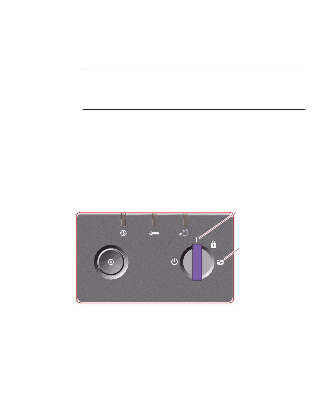
3. Insert the system key into the front panel keyswitch and turn it to the Normal or
Diagnostics position.
Normal position will enable the custom OpenBootTM configuration for diagnostic
testing as defined for your system.
Note – OpenBoot PROM Version 4.17.x provides diagnostics that are enabled by
default.
these enhancements, the new and redefined configuration variables, and the new
standard (default) configuration, refer to OpenBoot PROM Enhancements for Diagnostic
Operation Guide, which is included on the Sun Fire V890 Documentation CD.
Full OpenBoot Diagnostics run at initial power-on. For more information about
Diagnostics position will enable the standard default OpenBoot configuration for
running diagnostic tests. Your system will automatically run maximum POST and
OpenBoot Diagnostics tests and display the output. The system will also enable
automatic system recovery (ASR).
For information about the standard default Open Boot configuration for diagnostic
testing, refer to the OpenBoot PROM Enhancements for Diagnostic Operations Guide,
which is included on the Sun Fire V890 Documentation CD.
See “About Power Button and Keyswitch Settings” on page 14 for information about
each keyswitch setting.
Normal
position
Diagnostics
position
4. Press the Power button to the left of the keyswitch to power on the system.
Chapter 1 Preparing to Service the System 3
Page 32

Note – The system may take up to 30 minutes to run diagnostic tests and display
status messages before the ok prompt appears on the system console. The time
depends on the system configuration (number of CPUs, memory modules, and PCI
cards) and the configuration of the OpenBoot variables, which by default are set at
diag-level=max and verbosity=normal. To estimate boot time, and to
customize the standard configuration after initial power-on, refer to the OpenBoot
PROM Enhancements for Diagnostic Operation guide, which is included on the Sun
Fire V890 Documentation CD.
5. Turn the keyswitch to the Locked position.
This prevents anyone from accidentally powering off the system.
Locked
position
6. Remove the key from the keyswitch and keep it in a secure place.
What Next
The system’s front panel LED indicators provide power-on status information. For
more information about the system LEDs, see
page 259.
If your system encounters a problem during system startup, and the keyswitch is in
the Normal position, try restarting the system in the Diagnostics mode to determine
the source of the problem. Turn the front panel keyswitch to the Diagnostics position
and power cycle the system. See:
■ “How to Power Off the System” on page 5
4 Sun Fire V890 Server Service Manual • October 2005
“About Front Panel LEDs” on
Page 33

■ “How to Power On the System” on page 2
How to Power Off the System
What to Do
1. Notify users that the system will be powered down.
2. Back up the system files and data, if necessary.
3. Ensure that the front panel keyswitch is in the Normal or Diagnostics position.
Normal
position
Diagnostics
position
4. Press and release the Power button on the system front panel.
The system begins a graceful software system shutdown.
Note – Pressing and releasing the Power button initiates a graceful software system
shutdown. Pressing and holding in the Power button for five seconds causes an
immediate hardware shutdown. Whenever possible, you should use the graceful
shutdown method. Forcing an immediate hardware shutdown may cause disk drive
corruption and loss of data. Use this method only as a last resort.
5. Wait for the front panel Power/OK LED to turn off.
Chapter 1 Preparing to Service the System 5
Page 34

6. Turn the keyswitch to the Forced Off position.
Forced Off position
Caution – Be sure to turn the keyswitch to the Forced Off position before handling
any internal components. Otherwise, it is possible for a Remote System Control
(RSC) user to restart the system remotely while you are working inside it. The
Forced Off position is the only keyswitch position that prevents an RSC user from
restarting the system.
7. Remove the key from the keyswitch and keep it in a secure place.
About Hot-Pluggable and Hot-Swappable Components
Sun Fire V890 systems feature a variety of components that can be serviced while the
machine is running.
Hot-pluggable components are components that a qualified service technician can
install or remove while the system is running, without affecting the rest of the
system’s capabilities. However, in many cases, you must prepare the operating
system prior to the hot-plug event by performing certain system administration
tasks.
6 Sun Fire V890 Server Service Manual • October 2005
Page 35

Components that can be serviced without such preparation are called hot-swappable
components. These components can be removed or inserted at any time without
preparing the operating system in advance.
Sun Fire V890 hot-pluggable components fall into three basic groups:
■ Fan trays and power supplies
■ Disk drives
■ PCI cards
Each group is discussed in more detail in the sections that follow.
Note – PCI and disk hot-plug operations are not supported when the system ok
prompt is displayed. You can only perform these hot-plug operations while the
operating system is running.
Caution – The system controller (SC) card cannot be serviced while the system is
running. Before installing or removing a system controller card, you must power off
the system and disconnect all AC power cords.
Fan Trays and Power Supplies
Sun Fire V890 fan trays and power supplies are hot-swappable—they can be
removed or inserted at any time without requiring prior software preparations. Keep
in mind that a power supply is not considered hot-swappable unless it is part of an
N+1 redundant power configuration—a system configured with the third power
supply. Do not remove a power supply from a working system if its removal would
leave the system with fewer than two working power supplies.
You can install or remove a power supply or fan tray while the system is operating
at the ok prompt. However, in the case of the power supply, you must issue a
reset-all command at the ok prompt in order for the change to be recognized the
next time the operating system is booted.
Note – If you remove a power supply or fan tray while the operating system is
running, wait for an acknowledgement message on the system console before
installing a replacement part; otherwise, the environmental monitoring software will
not recognize the new device and false error conditions will result.
Caution – When hot-swapping a redundant fan tray, do not put your hand into the
empty fan tray bay. The fans in the populated bay are still spinning.
Chapter 1 Preparing to Service the System 7
Page 36

For additional information, see:
■ “About Power Supplies” on page 231
■ “About Fan Trays” on page 234
Disk Drives
Sun Fire V890 internal disk drives are hot-pluggable. However, certain software
preparations are required. To perform Sun Fire V890 disk drive hot-plug operations,
you use the Solaris luxadm utility. The luxadm utility is a command-line tool for
managing intelligent storage arrays such as Sun StorEdge
arrays or Sun Fire V890 internal storage arrays.
For more information about luxadm, refer to the Sun Fire V890 Server Owner’s Guide.
For complete disk hot-plug procedures, refer to Platform Notes: Using luxadm
Software, which is available on the Sun Fire V890 Documentation CD. Refer also to
the Sun Fire V890 Server Product Notes for late-breaking details.
Caution – When hot-plugging a disk drive, after disconnecting the drive from its
backplane, allow 30 seconds or so for the drive to spin down completely before
removing it from its drive bay.
TM
A5x00 series disk
PCI Cards
On Sun Fire V890 systems, PCI cards are hot-pluggable, while the system controller
card cannot be serviced when the machine is running.
Hot-plug operations for PCI cards involve Dynamic Reconfiguration (DR). DR is an
operating system feature that provides the ability to reconfigure system hardware
while the system is running. DR lets you logically attach or detach hardware
resources within an active operating system. The main benefit of DR is that a service
provider can add or replace hardware resources with little or no impact on normal
system operations.
PCI card hot-plug procedures may involve software commands for preparing the
system prior to removing a device, and for reconfiguring the operating system after
installing a new device. In addition, certain system requirements must be met in
order for hot-plug operations to succeed.
For information about system requirements and limitations, and for detailed PCI
card hot-plug procedures, refer to the Sun Fire V890 Dynamic Reconfiguration User’s
Guide, which is available at
Hardware. Refer to the Sun Fire V890 Server Product Notes for late-breaking details.
8 Sun Fire V890 Server Service Manual • October 2005
http://docs.sun.com, under Solaris on Sun
Page 37

Caution – You can hot-plug any standard PCI card that complies with PCI Hot-Plug
Specification Revision 1.1, provided a suitable software driver exists for the Solaris
Operating System, and the driver supports hot-plugging as described in the Sun Fire
V890 Dynamic Reconfiguration User’s Guide. The Sun Fire V890 system must be
running the Solaris
8 7/01 Operating System or a subsequent release that supports
Sun Fire V890 PCI hot-plug operations. Do not attempt to hot-plug a PCI card until
you are certain that its device drivers provide the proper support; otherwise, you
may cause a system panic. For a list of Sun PCI cards and device drivers that
support PCI hot-plug operations, refer to the Sun Fire V890 Server Product Notes.
Note – DR works in conjunction with (but does not require) multipathing software.
You can use multipathing software to switch I/O operations from one I/O controller
to another to prepare for DR operations. With a combination of DR and multipathing
software, you can remove, replace, or deactivate a PCI controller card with little or
no interruption to system operation. Note that this requires redundant hardware;
that is, the system must contain an alternate I/O controller that is connected to the
same devices as the card being removed or replaced. The alternate controller must
reside on a different PCI card or be integrated into the Sun Fire V890 system
motherboard or I/O board. For additional details, refer to the Sun Fire V890 Server
Owner’s Guide.
Chapter 1 Preparing to Service the System 9
Page 38

PCI Hot-Plug User Interfaces
There are two different methods for performing PCI hot-plug operations on Sun Fire
V890 systems:
■ Push-button method
■ Command-line method
The push-button method relies on push buttons and status LEDs located near each
PCI slot. You can initiate a hot-plug operation by pressing the push button for the
corresponding slot. The command-line method lets you perform hot-plug operations
via a remote login session, a Remote System Control (RSC) console, or a locally
attached console. This method involves the Solaris cfgadm(1) command.
Both hot-plug methods make use of the status LEDs located near each PCI slot.
These LEDs indicate where and when it is safe to insert or remove a card, and also
show whether the operation has succeeded or failed. For additional details on hotplug status LEDs, see
Note – Regardless of the method you use, it is often necessary to perform additional
administrative steps to prepare for a hot-plug removal operation. Prior to
performing a removal operation, you must ensure that the devices residing on the
board are not currently in use. To identify and manually terminate usage of such
devices, you can use standard Solaris Operating System commands such as
mount(1M), umount(1M), swap(1M), ifconfig(1M), and ps(1).
“About PCI Slot LEDs” on page 263.
For detailed PCI hot-plug procedures, refer to the Sun Fire V890 Dynamic
Reconfiguration User’s Guide, which is available at
Solaris on Sun Hardware. Refer to the Sun Fire V890 Server Product Notes for latebreaking details.
How to Initiate a Reconfiguration Boot
After installing any new internal option or external storage device, you must
perform a reconfiguration boot so that the operating system is able to recognize any
newly installed devices. In addition, if you remove any device and do not install a
replacement device prior to rebooting the system, you must perform a
reconfiguration boot in order for the operating system to recognize the configuration
change. This requirement also applies to any component that is connected to the
system’s I
supplies.
10 Sun Fire V890 Server Service Manual • October 2005
2
C bus, including memory modules, CPU/Memory boards, and power
http://docs.sun.com, under
Page 39

This requirement does not apply to any component that is:
■ Installed or removed as part of a hot-plug operation
■ Installed or removed before the operating system is installed
■ Installed as an identical replacement for a component that is already recognized
by the operating system
Caution – All internal options (except disk drives and power supplies) must be
installed only by qualified service personnel.
Before You Begin
Caution – Before you power on the system, make sure that the front and side doors
and all plastic outer panels are properly installed.
You need a system console in order to issue software commands. See:
■ “About Setting Up a Console” on page 16.
What to Do
1. Turn on power to any peripherals and external storage devices.
Read the documentation supplied with the device for specific instructions.
2. Turn on power to the console.
3. Insert the system key into the front panel keyswitch and turn the keyswitch to the
Diagnostics position.
Chapter 1 Preparing to Service the System 11
Page 40

4. Press the Power button to the left of the keyswitch to power on the system.
The system will automatically run power-on self-test (POST) and OpenBoot
Diagnostics tests and display the output.
Diagnostics
position
5. When the diagnostics tests are completed, and the system banner is displayed on
the system console, immediately abort the boot process to access the system ok
prompt.
The system banner contains the Ethernet address and host ID.
Note – The system may take up to 30 minutes to run diagnostic tests and display
status messages before the ok prompt appears on the system console. The time
depends on the system configuration (number of CPUs, memory modules, and PCI
cards) and the standard default configuration of the OpenBoot variables, which by
default are set at diag-level=max and verbosity=normal. To customize the
standard configuration after initial power-on, refer to the OpenBoot PROM
Enhancements for Diagnostic Operation guide, which is included on the Sun Fire V890
Documentation CD.
12 Sun Fire V890 Server Service Manual • October 2005
Page 41

6. At the ok prompt, type:
ok env-on
Environmental monitor is ON
ok boot -r
The env-on command re-enables the OpenBoot environmental monitor, which may
have been disabled as a result of the abort key sequence. The boot -r command
rebuilds the device tree for the system, incorporating any newly installed options so
that the operating system will recognize them.
7. Turn the keyswitch to the Locked position, remove the key, and keep it in a secure
place.
This prevents anyone from accidentally powering off the system.
Locked
position
What Next
The system’s front panel LED indicators provide power-on status information. For
more information about the system LEDs, see
page 259.
If your system encounters a problem during system start-up, and the keyswitch is in
the Normal position, try restarting the system with the keyswitch in the Diagnostics
position to determine the source of the problem. Turn the front panel keyswitch to
the Diagnostics position and power cycle the system.
“About Front Panel LEDs” on
Chapter 1 Preparing to Service the System 13
Page 42

About Power Button and Keyswitch Settings
System Power Button
The system Power button is recessed to prevent accidentally turning the system on
or off. The ability of the Power button to turn the system on or off is controlled by
the security keyswitch.
If the operating system is running, pressing and releasing the Power button initiates
a graceful software system shutdown. Pressing and holding in the Power button for
five seconds causes an immediate hardware shutdown.
Note – Whenever possible, you should use the graceful shutdown method. Forcing
an immediate hardware shutdown may cause disk drive corruption and loss of data.
Use this method only as a last resort.
Power button
14 Sun Fire V890 Server Service Manual • October 2005
Page 43

Security Keyswitch
The four-position security keyswitch controls the power-on modes of the system and
prevents unauthorized users from powering off the system or reprogramming
system firmware. The following table describes the function of each keyswitch
setting.
Position Icon Description
Normal This setting enables the system Power button to power the
system on or off. If the operating system is running, pressing
and releasing the Power button initiates a graceful software
system shutdown. Pressing and holding the Power button in
for five seconds causes an immediate hardware power off.
OpenBoot PROM Version 4.17.x provides diagnostics that are
enabled by default.
power-on. For more information about these
enhancements, the new and redefined configuration
variables, and the new standard (default) configuration, refer
to OpenBoot PROM Enhancements for Diagnostic Operation
Guide, which is included on the Sun Fire V890 Documentation
CD.
Locked The Locked setting:
• Disables the system Power button to prevent unauthorized
users from powering the system on or off
• Disables the keyboard Stop-A command, terminal Break key
command, ~# tip window command, and RSC break
command, preventing users from suspending system
operation to access the system ok prompt
• Prevents unauthorized programming of the system flash
PROMs
The Locked position is the recommended setting for normal
day-to-day operations.
Full OpenBoot Diagnostics run at initial
Chapter 1 Preparing to Service the System 15
Page 44

Position Icon Description
Diagnostics This setting forces the power-on self-test (POST) and
OpenBoot Diagnostics to run during system startup. The
Power button functions the same as when the keyswitch is in
the Normal position.
Forced Off This setting forces the system to power off immediately and
enter 5-volt standby mode. It also disables the system Power
button. You may want to use this setting when AC power is
interrupted and you do not want the system to restart
automatically when power is restored. With the keyswitch in
any other position, if the system was running prior to losing
power, it restarts automatically once power is restored.
The Forced Off setting also prevents an RSC console from
restarting the system. However, the service controller card
continues to operate using the system’s 5-volt standby power.
About Setting Up a Console
To install your server or to diagnose problems, you need some way to enter system
commands and to view system output. There are four ways to do this.
1. Attach an alphanumeric (ACSII) character terminal to serial port A.
You can attach a simple terminal to serial port A. For instructions, see “How to
Initiate a Reconfiguration Boot” on page 10.
2. Establish a tip connection from another Sun system.
For information about establishing a tip connection, refer to the OpenBoot 4.x
Command Reference Manual, which is available at
Solaris on Sun Hardware. Refer to the Sun Fire V890 Server Product Notes for latebreaking details.
3. Install a local graphics console on your server.
The server is often shipped without a mouse, keyboard, monitor, or frame buffer for
the display of graphics. To install a local graphics console on a server, you must
install a graphics frame buffer card in a PCI slot, and attach a monitor, mouse, and
keyboard to the appropriate rear panel ports. For detailed instructions, see
Configure a Local Graphics Console” on page 19.
Note – Power-on self-test (POST) messages are output to serial port A (ttya) or the
RSC console only.
16 Sun Fire V890 Server Service Manual • October 2005
http://docs.sun.com, under
“How to
Page 45

4. Set up a Remote System Control (RSC) console.
RSC is a remote server management tool that lets you monitor and control your
server over serial lines or over a network. RSC provides remote system
administration for geographically distributed or physically inaccessible systems. For
additional details, refer to your Sun Fire V890 Server Owner’s Guide.
Note – You cannot use an RSC console to perform the initial installation of the
Solaris OS. The operating system must be installed prior to setting up an RSC
console. Once you install the operating system and the RSC software, you can
configure the system to use RSC as the system console. For detailed instructions,
refer to your Sun Fire V890 Server Owner’s Guide.
How to Attach an Alphanumeric Terminal
Before You Begin
If your server is configured without a local graphics console, you need to attach an
alphanumeric (ASCII) terminal to the server in order to install the operating system
and to run diagnostic tests. Alternatively, you can install a local graphics console,
create a tip connection from another Sun system, or set up an RSC console. See:
■ “About Setting Up a Console” on page 16
■ “How to Configure a Local Graphics Console” on page 19
Note – You cannot use an RSC console to perform the initial installation of the
Solaris OS. The Solaris OS must be installed prior to setting up an RSC console.
What to Do
1. Connect a DB-25 null modem serial cable or a DB-25 serial cable and null modem
adapter to the terminal’s serial port.
Chapter 1 Preparing to Service the System 17
Page 46

2. Connect the opposite end of the cable to the system’s serial port connector or to
serial port A on
the serial splitter cable.
3. Connect the terminal’s power cable to an AC outlet.
4. Set the terminal to receive:
■ At 9600 baud
■ An 8-bit signal with no parity and 1 stop bit
See the documentation accompanying your terminal for more information.
What Next
You can now issue system commands and view system messages. Continue with
your installation or diagnostic procedure as needed.
18 Sun Fire V890 Server Service Manual • October 2005
Page 47

How to Configure a Local Graphics Console
Before You Begin
If your server is configured without a local alphanumeric terminal, you need to
install a local graphics console in order to install the operating system and to run
diagnostic tests. Alternatively, you can attach an alphanumeric (ASCII) terminal,
create a tip connection from another Sun system, or set up an RSC console. See:
■ “About Setting Up a Console” on page 16
■ “How to Attach an Alphanumeric Terminal” on page 17
Note – You cannot use an RSC console to perform the initial installation of the
Solaris OS. The Solaris OS must be installed prior to setting up an RSC console.
To install a local graphics console, you must have:
■ A supported PCI-based graphics frame buffer card and software driver
■ A monitor with appropriate resolution
■ A Sun Type-6 USB keyboard
■ A Sun-compatible USB three-button mouse
What to Do
1. Install the graphics card into a vacant PCI slot.
See “How to Install a PCI Card” on page 83.
Chapter 1 Preparing to Service the System 19
Page 48

2. Attach the monitor video cable to the graphic card’s video port.
Tighten the thumbscrews to secure the connection.
3. Connect the monitor’s power cord to an appropriate AC power outlet.
4. Attach the keyboard cable to one of the system’s USB ports.
5. Attach the mouse cable to the system’s remaining USB port, or to a USB port on
the keyboard, if applicable.
20 Sun Fire V890 Server Service Manual • October 2005
Page 49

What Next
You can now issue system commands and view system messages. Continue with
your service or diagnostic procedure as needed.
How to Open and Remove a Side Door
Before You Begin
If you are not performing a hot-plug procedure, complete the following task:
■ “How to Power Off the System” on page 5
What to Do
1. Use the system key to unlock the door.
Chapter 1 Preparing to Service the System 21
Page 50

2. Swing the side door open.
3. To remove the door from the chassis, open the door 90 degrees and pull it up until
its mounting pins clear the brackets on the rear panel.
What Next
To reassemble the system side door, complete the following task:
■ “How to Close a Side Door” on page 23
22 Sun Fire V890 Server Service Manual • October 2005
Page 51

How to Close a Side Door
What to Do
1. If you removed the side door, remount it to the chassis.
Position the side door mounting pins over the corresponding holes in the chassis
rear panel and lower the side door into place.
2. Close the side door.
Make sure that the door is firmly seated in its frame.
Chapter 1 Preparing to Service the System 23
Page 52

3. Lock the side door with the system key.
24 Sun Fire V890 Server Service Manual • October 2005
Page 53

Locating Rear Panel Features
The following figure shows the system features that are accessible from the rear
panel.
SC Gigabit
Ethernet interface
USB B
USB A
Serial port A/B
SC card
Grounding screw
Power supply 2
PCI slot 8
PCI slot 7
PCI slot 6
PCI slot 5
PCI slot 4
PCI slot 3
PCI slot 2
PCI slot 1
PCI slot 0
TPE Fast
Ethernet
interface
Power supply 0
Power supply 1
A grounding screw is located just above the center power supply. When installing a
a Sun Fire V890 server into a rack, or connecting the server to an external storage
array, be sure to connect an appropriate grounding strap between the server’s
grounding screw and the grounding screw on the rack enclosure or external storage
array. A grounding strap prevents ground loops between systems and peripherals
and helps guard against possible data loss.
Chapter 1 Preparing to Service the System 25
Page 54

How to Avoid Electrostatic Discharge
Use the following procedure to prevent static damage whenever you are accessing
any of the internal components of the system.
Before You Begin
Complete this task if you are working with a component that is not hot-pluggable:
■ “How to Power Off the System” on page 5
You must have the following items:
■ Antistatic wrist or foot strap
■ Antistatic mat (or the equivalent)
What to Do
Caution – Printed circuit boards and hard disk drives contain electronic
components that are extremely sensitive to static electricity. Ordinary amounts of
static from your clothes or the work environment can destroy components.
Do
not touch the components or any metal parts without taking proper antistatic
precautions.
1. Disconnect the AC power cord from the wall power outlet only when performing
the following procedures:
■ Removing and installing the system controller card
■ Removing and installing the I/O board
■ Removing and installing the power distribution board
The AC power cord provides a discharge path for static electricity, so it should
remain plugged in except when you are servicing the parts noted above.
26 Sun Fire V890 Server Service Manual • October 2005
Page 55

2. Use an antistatic mat or similar surface.
When performing any option installation or service procedure, place static-sensitive
parts, such as boards, cards, and disk drives, on an antistatic surface. The following
items can be used as an antistatic surface:
■ The bag used to wrap a Sun replacement part
■ The shipping container used to package a Sun replacement part
■ Sun electrostatic discharge (ESD) mat, Sun part number 250-1088 (available
through your Sun sales representatives)
■ Disposable ESD mat, shipped with replacement parts or options
3. Use an antistatic wrist strap.
Attach one end of the strap to the system chassis sheet metal, and attach the other
end to your wrist. Refer to the instructions that come with the strap.
Note – Make sure that the wrist strap is in direct contact with the metal on the
chassis.
4. Detach both ends of the strap after you complete the installation or service
procedure.
Chapter 1 Preparing to Service the System 27
Page 56

Tools Required for Installation and Service
The following tools are required to install and service the system:
■ Screwdriver, Phillips No. 1
■ Screwdriver, Phillips No. 2
■ Nut driver, 3/16ths inch
■ Electrostatic discharge (ESD) mat, Sun part number 250-1088, or equivalent
■ Grounding wrist or foot strap
The latter two items help protect the server against damage due to electrostatic
discharge. For more information, see
page 26.
“How to Avoid Electrostatic Discharge” on
28 Sun Fire V890 Server Service Manual • October 2005
Page 57

CHAPTER
2
Servicing the Motherboard Side Components
This chapter describes how to remove and install the system motherboard and
components on the motherboard side of the system. For a list of part numbers for
field-replaceable units (FRUs) and optional equipment, see
Breakdown” on page 247.
The following tasks are covered in this chapter:
■ “How to Remove a CPU/Memory Board” on page 30
■ “How to Install a CPU/Memory Board” on page 34
■ “How to Remove a Memory Module” on page 40
■ “How to Install a Memory Module” on page 44
■ “How to Remove a CPU Fan Tray” on page 48
■ “How to Install a CPU Fan Tray” on page 50
■ “How to Remove a Motherboard Fan Tray” on page 52
■ “How to Install a Motherboard Fan Tray” on page 55
■ “How to Remove the CPU Fan Status Assembly” on page 57
■ “How to Install the CPU Fan Status Assembly” on page 60
■ “How to Remove the CPU/Memory Board Status Assembly” on page 61
■ “How to Install the CPU/Memory Board Status Assembly” on page 63
■ “How to Remove the Motherboard Fan Status Flex Circuit” on page 64
■ “How to Install the Motherboard Fan Status Flex Circuit” on page 65
■ “How to Remove the Motherboard” on page 66
■ “How to Install the Motherboard” on page 70
“Illustrated Parts
29
Page 58

How to Remove a CPU/Memory Board
You must remove the CPU/Memory board to service the memory modules.
Caution – Either a CPU/Memory board or an air baffle must be installed in each
CPU/Memory slot at all times. After removing a CPU/Memory board, you must
install a replacement board or an air baffle immediately to avoid an automatic
thermal shutdown. For more information, see
page 218.
Note – Use only Sun Fire V890 CPU/Memory boards in the Sun Fire V890 system.
Before You Begin
Complete these tasks:
■ “How to Power Off the System” on page 5
■ “How to Open and Remove a Side Door” on page 21
■ “How to Avoid Electrostatic Discharge” on page 26
“About CPU/Memory Boards” on
What to Do
1. Identify the CPU/Memory board that you want to remove.
30 Sun Fire V890 Server Service Manual • October 2005
Page 59

2. Loosen the two captive screws securing the CPU/Memory board.
3. Rotate the green CPU/Memory board ejection levers outward so that the
CPU/Memory board connectors disengage from the motherboard.
Chapter 2 Servicing the Motherboard Side Components 31
Page 60

4. Pull the CPU/Memory board from the chassis.
5. Place the CPU/Memory board on an antistatic mat.
6. If you are not immediately replacing the CPU/Memory board, install a CPU air
baffle into its slot next to the CPU fan trays.
Caution – A CPU air baffle must be installed into an empty CPU/Memory board
slot to ensure proper cooling of the system. Spare CPU air baffles are located under
the CPU side chassis top.
32 Sun Fire V890 Server Service Manual • October 2005
Page 61

a. Align the air baffle so that the tab on the end is under its slot in the chassis.
b. Rotate the air baffle into position.
c. Push in the plastic pin on the air baffle.
7. If you are not immediately replacing the CPU/Memory board, install a
CPU/Memory board dust cover on that slot’s motherboard CPU/Memory board
connectors.
Chapter 2 Servicing the Motherboard Side Components 33
Page 62

What Next
If you are installing a replacement CPU/Memory board, you must transfer all
memory modules from the faulty board to the replacement board. Complete these
tasks:
■ “How to Remove a Memory Module” on page 40
■ “How to Install a Memory Module” on page 44
To reassemble the system, complete this task:
■ “How to Close a Side Door” on page 23
If you are not replacing the part right away, you need to perform a reconfiguration
boot. A reconfiguration boot is required in order for the operating system to
recognize the configuration change. See:
■ “How to Initiate a Reconfiguration Boot” on page 10
How to Install a CPU/Memory Board
Before You Begin
Caution – If a CPU/Memory board connector dust cover is installed on the
motherboard CPU/Memory board connectors in the slot where you are installing
the CPU/Memory board, you must remove it. If you have not removed the dust
cover from the motherboard, installing a CPU/Memory board in that slot may
damage the motherboard and the CPU/Memory board.
Note – Use only Sun Fire V890 CPU/Memory boards in the Sun Fire V890 system.
Complete the following tasks:
■ “How to Power Off the System” on page 5
■ “How to Open and Remove a Side Door” on page 21
■ “How to Avoid Electrostatic Discharge” on page 26
34 Sun Fire V890 Server Service Manual • October 2005
Page 63

If you are replacing a faulty CPU/Memory board with a new one, you must transfer
the memory modules from the faulty CPU/Memory board to the new one. See the
following sections for more information about transferring memory modules:
■ “About Memory Modules” on page 221
■ “How to Remove a Memory Module” on page 40
■ “How to Install a Memory Module” on page 44
What to Do
1. Locate the CPU/Memory board slot into which you want to install the
CPU/Memory board.
2. If a CPU/Memory board connector dust cover is installed on the slot’s
motherboard CPU/Memory board connectors, remove it.
Caution – If you have not removed the dust cover from the motherboard
CPU/Memory board connectors, installing a CPU/Memory board in that slot may
damage the motherboard and the CPU/Memory board.
Chapter 2 Servicing the Motherboard Side Components 35
Page 64

3. If a CPU air baffle is installed in the CPU/Memory board’s slot, remove the air
baffle.
a. Pull the plastic tab on the air baffle and rotate the baffle from its slot.
b. Place the CPU air baffle into an empty CPU air baffle slot on the underside of
the chassis top.
36 Sun Fire V890 Server Service Manual • October 2005
Page 65

4. Make sure that the green ejection levers on the CPU/Memory board are rotated
out at least 90 degrees.
5. Slide the CPU/Memory board into the guides in the chassis.
Slide the board into the system until the connectors on the board begin to engage the
sockets on the motherboard and the ejection levers begin to contact the bracket.
Chapter 2 Servicing the Motherboard Side Components 37
Page 66

6. Push in the two ejection levers simultaneously until the board is fully engaged in
its slot.
7. Hand-tighten the two captive screws on the CPU/Memory board.
38 Sun Fire V890 Server Service Manual • October 2005
Page 67

8. Using a No. 2 Phillips screwdriver, fully tighten the right-side captive screw and
repeat for the left-side screw.
1
2
What Next
To reassemble the system, complete this task:
■ “How to Close a Side Door” on page 23
If you installed this part as a new option, you need to perform a reconfiguration
boot. A reconfiguration boot is required in order for the operating system to
recognize the new device. See:
■ “How to Initiate a Reconfiguration Boot” on page 10
Note – Be sure to run POST and OpenBoot Diagnostics tests to verify that the
system functions correctly with the parts you have just installed. Refer to OpenBoot
PROM Enhancements for Diagnostic Operation on the Sun Fire V890 Documentation
CD.
Chapter 2 Servicing the Motherboard Side Components 39
Page 68

How to Remove a Memory Module
Before You Begin
Read the section “About Memory Modules” on page 221.
Complete these tasks:
■ “How to Power Off the System” on page 5
■ “How to Open and Remove a Side Door” on page 21
■ “How to Avoid Electrostatic Discharge” on page 26
■ “How to Remove a CPU/Memory Board” on page 30
What to Do
Caution – Dual inline memory modules (DIMMs) are made of electronic
components that are extremely sensitive to static electricity. Static electricity from
your clothes or work environment can destroy the DIMM. Do not remove any
DIMM from its antistatic packaging until you are ready to install it. Handle the
modules only by their edges. Do not touch the components or any metal parts,
including the gold contacts on the bottom edge of the module. Always wear a
grounding strap when you handle the modules.
40 Sun Fire V890 Server Service Manual • October 2005
Page 69

1. Remove the plastic cover on the CPU/Memory board.
Push the tabs inward until you can lift the cover free of the CPU/Memory board
shroud.
2. Identify the memory module that you want to remove.
Chapter 2 Servicing the Motherboard Side Components 41
Page 70

3. Push down on the ejection levers at each end of the memory module until the
memory module pops out of its socket.
Apply even pressure on both levers.
4. Grasp the top corners of the memory module and pull it up and out of its socket.
5. Place the memory module on an antistatic mat.
42 Sun Fire V890 Server Service Manual • October 2005
Page 71

6. If you are not installing replacement memory modules immediately, replace the
plastic cover on the CPU/Memory board.
To fully engage the tabs on the cover, push both tabs at the same time until you hear
a click.
What Next
To replace a memory module, complete this task:
■ “How to Install a Memory Module” on page 44
To reassemble the system, complete these tasks:
■ “How to Install a CPU/Memory Board” on page 34
■ “How to Close a Side Door” on page 23
If you are not replacing the part right away, you need to perform a reconfiguration
boot. A reconfiguration boot is required in order for the operating system to
recognize the configuration change. See:
■ “How to Initiate a Reconfiguration Boot” on page 10
Chapter 2 Servicing the Motherboard Side Components 43
Page 72

How to Install a Memory Module
Before You Begin
Read the section “About Memory Modules” on page 221.
Complete these tasks:
■ “How to Power Off the System” on page 5
■ “How to Open and Remove a Side Door” on page 21
■ “How to Avoid Electrostatic Discharge” on page 26
■ “How to Remove a CPU/Memory Board” on page 30
What to Do
Caution – Dual inline memory modules (DIMMs) are made of electronic
components that are extremely sensitive to static electricity. Static electricity from
your clothes or work environment can destroy the DIMM. Do not remove any
DIMM from its antistatic packaging until you are ready to install it. Handle the
modules only by their edges. Do not touch the components or any metal parts,
including the gold contacts on the bottom edge of the module. Always wear a
grounding strap when you handle the modules.
44 Sun Fire V890 Server Service Manual • October 2005
Page 73

1. Remove the plastic cover on the CPU/Memory board.
Push the tabs inward until you can lift the cover free of the CPU/Memory board
shroud.
2. Locate the slot into which you will install the memory module.
3. Rotate outward the memory module ejection levers for that slot.
Chapter 2 Servicing the Motherboard Side Components 45
Page 74

4. Holding the bottom edge of the module parallel to its socket, carefully align the
module so that each of its contacts is centered on a socket pin.
5. Push firmly and evenly on both ends of the memory module until its bottom edge
is firmly seated in the socket.
You will hear a click when the ejection levers are in the locked position.
46 Sun Fire V890 Server Service Manual • October 2005
Page 75

6. Replace the plastic cover on the CPU/Memory board.
To fully engage the tabs on the cover, push both tabs at the same time until you hear
a click.
What Next
To reassemble the system, complete these tasks:
■ “How to Install a CPU/Memory Board” on page 34
■ “How to Close a Side Door” on page 23
If you installed this part as a new option, you need to perform a reconfiguration
boot. A reconfiguration boot is required in order for the operating system to
recognize the new device. See:
■ “How to Initiate a Reconfiguration Boot” on page 10
Note – Be sure to run POST and OpenBoot Diagnostics tests to verify that the
system functions correctly with the parts you have just installed. Refer to OpenBoot
PROM Enhancements for Diagnostic Operation on the Sun Fire V890 Documentation
CD.
Chapter 2 Servicing the Motherboard Side Components 47
Page 76

How to Remove a CPU Fan Tray
Caution – At least one CPU fan tray, one I/O fan tray, and one motherboard fan
tray must be installed and operating to ensure proper system cooling; otherwise, the
system will initiate an automatic thermal shutdown.
The primary CPU fan tray is in slot 1. If a CPU fan tray fails and you do not have a
replacement available, leave the failed CPU fan tray installed to ensure proper
system cooling. The failed fan tray acts as a baffle channeling airflow to cool the
CPU/Memory module. For more information about CPU fan trays, see
Trays” on page 234.
All fan trays feature a hot-swap capability. You can remove and replace a faulty fan
tray without shutting down the operating system or turning off the system power.
For additional details, see
on page 6.
“About Hot-Pluggable and Hot-Swappable Components”
Note – Use only Sun Fire V890 CPU fan trays in the Sun Fire V890 system.
Before You Begin
“About Fan
If you are not performing a hot-swap procedure, complete the following task:
■ “How to Power Off the System” on page 5
Complete these tasks:
■ “How to Open and Remove a Side Door” on page 21
■ “How to Avoid Electrostatic Discharge” on page 26
What to Do
1. Identify the CPU fan tray that you want to remove.
The primary CPU fan tray occupies CPU fan tray slot 1. For information about CPU
fan tray LEDs, see
48 Sun Fire V890 Server Service Manual • October 2005
“About Fan Tray LEDs” on page 266.
Page 77

2. Loosen the two captive screws holding the CPU fan tray in the chassis.
3. Slide the fan tray out from the system.
Caution – If you are performing a hot-swap procedure, do not put your hand into
the empty fan bay. The fans in the populated fan tray are still spinning.
Caution – You must install a replacement fan tray immediately to ensure proper
system cooling.
Chapter 2 Servicing the Motherboard Side Components 49
Page 78

What Next
Note – During a hot-swap operation, after you remove a fan tray or power supply,
wait for an acknowledgement message on the system console before installing a
replacement part; otherwise, the environmental monitoring software will not
recognize the new device and false error conditions will result.
To replace the CPU fan tray, complete this task:
■ “How to Install a CPU Fan Tray” on page 50
To reassemble the system, complete this task:
■ “How to Close a Side Door” on page 23
How to Install a CPU Fan Tray
All fan trays feature a hot-swap capability. You can remove and replace a faulty fan
tray without shutting down the operating system or turning off the system power.
For additional details, see
on page 6.
“About Hot-Pluggable and Hot-Swappable Components”
Note – Use only Sun Fire V890 CPU fan trays in the Sun Fire V890 system.
Before You Begin
If you are not performing a hot-swap procedure, complete the following task:
■ “How to Power Off the System” on page 5
Complete these tasks:
■ “How to Open and Remove a Side Door” on page 21
■ “How to Avoid Electrostatic Discharge” on page 26
50 Sun Fire V890 Server Service Manual • October 2005
Page 79

What to Do
1. Identify the slot into which you want to install the CPU fan tray.
The primary CPU fan tray occupies CPU fan tray slot 1. For information about CPU
fan tray LEDs, see
Caution – If you are performing a hot-swap procedure, do not put your hand into
the empty fan bay. The fans in the populated fan tray are still spinning.
2. Align the CPU fan tray with its slot in the chassis.
The arrow label on the fan tray indicates the top side of the fan tray.
3. Slide the fan tray into the chassis until the connector on the fan tray is firmly
seated in its socket.
“About Fan Tray LEDs” on page 266.
4. Tighten the two captive screws on the fan tray.
What Next
To reassemble the system, complete this task:
Chapter 2 Servicing the Motherboard Side Components 51
Page 80

■ “How to Close a Side Door” on page 23
If you installed this part as a new option while the system was powered off, you
need to perform a reconfiguration boot. A reconfiguration boot is required in order
for the operating system to recognize the new device. See:
■ “How to Initiate a Reconfiguration Boot” on page 10
How to Remove a Motherboard Fan Tray
Caution – At least one CPU fan tray, one I/O fan tray, and one motherboard fan
tray must be installed and operating to ensure proper system cooling; otherwise, the
system will initiate an automatic thermal shutdown.
Note – The motherboard fan tray is also referred to as the I/O bridge fan tray by the
system’s firmware and environmental software. For more information about
motherboard fan trays, see “About Fan Trays” on page 234.
All fan trays feature a hot-swap capability. You can remove and replace a faulty fan
tray without shutting down the operating system or turning off the system power.
For additional details, see
on page 6.
“About Hot-Pluggable and Hot-Swappable Components”
Before You Begin
If you are not performing a hot-swap procedure, complete the following task:
■ “How to Power Off the System” on page 5
Complete these tasks:
■ “How to Open and Remove a Side Door” on page 21
■ “How to Avoid Electrostatic Discharge” on page 26
What to Do
1. Identify the motherboard fan tray that you want to remove.
The primary motherboard fan tray occupies slot 5. The fan tray numbers are
stamped into the chassis sheet metal at the base of each fan tray.
52 Sun Fire V890 Server Service Manual • October 2005
Page 81

2. Unplug the motherboard fan tray cable from the fan tray you are going to remove.
If you are removing a redundant fan tray, drape the cable away from the other fan.
Caution – If you are performing a hot-swap procedure, do not put your hand into
the empty fan bay. The fan in the populated fan tray is still spinning.
3. Loosen the captive screw on the fan tray you are going to remove.
4. If you are removing fan tray 5 and fan tray 6 is installed, disconnect the cable to
fan tray 6 and drape it out of the way so that you can remove fan tray 5.
Note – When both motherboard fan trays are not operational in a running Sun Fire
V890 system, the environmental monitoring software generates warning messages
that the fan trays are removed. If an operational fan tray is not installed quickly, the
system may initiate a thermal shutdown. During motherboard fan tray hot-swap
procedures, to avoid these messages and potential cooling issues resulting in a
system thermal shutdown, reconnect the motherboard fan tray cables for functional
fans as soon as possible.
Chapter 2 Servicing the Motherboard Side Components 53
Page 82

5. Slide the fan tray you are removing out of the system.
6. If you disconnected the cable to fan tray 6 to remove fan tray 5, reconnect the
cable to fan tray 6.
If you disconnected the cable to fan tray 6 as part of a hot-swap procedure for fan
tray 5 and you are immediately replacing fan tray 5, do not reconnect the cable to
fan tray 6 until you install fan tray 5.
What Next
Note – During a hot-swap operation, after you remove a fan tray or power supply,
wait for an acknowledgement message on the system console before installing a
replacement part; otherwise, the environmental monitoring software will not
recognize the new device and false error conditions will result.
To replace the motherboard fan tray, complete this task:
■ “How to Install a Motherboard Fan Tray” on page 55
To reassemble the system, complete this task:
■ “How to Close a Side Door” on page 23
54 Sun Fire V890 Server Service Manual • October 2005
Page 83

How to Install a Motherboard Fan Tray
Note – The motherboard fan tray is also referred to as the I/O bridge fan tray by the
system’s firmware and environmental software. For more information about
motherboard fan trays, see “About Fan Trays” on page 234.
All fan trays feature a hot-swap capability. You can remove and replace a faulty fan
tray without shutting down the operating system or turning off the system power.
For additional details, see
on page 6.
Before You Begin
If you are not performing a hot-swap procedure, complete the following task:
■ “How to Power Off the System” on page 5
Complete these tasks:
■ “How to Open and Remove a Side Door” on page 21
■ “How to Avoid Electrostatic Discharge” on page 26
What to Do
“About Hot-Pluggable and Hot-Swappable Components”
1. Locate the slot into which you will install the motherboard fan tray.
a. If you are installing fan tray 5 and fan tray 6 is installed, disconnect the cable to
fan tray 6.
The primary motherboard fan tray occupies slot 5. The fan tray numbers are
stamped into the chassis sheet metal at the base of each fan tray.
Note – When both motherboard fan trays are not operational in a running Sun Fire
V890 system, the environmental monitoring software generates warning messages
that the fan trays are removed. If an operational fan tray is not installed quickly, the
system may initiate a thermal shutdown. During motherboard fan tray hot-swap
procedures, to avoid these messages and potential cooling issues resulting in a
system thermal shutdown, reconnect the motherboard fan tray cables for functional
fans as soon as possible.
Chapter 2 Servicing the Motherboard Side Components 55
Page 84

Note – Ensure that the fan tray cable is not in the path of the fan tray that you will
install.
2. Align the fan tray to be installed with its plastic guide in the chassis.
3. Slide the fan tray into the chassis.
4. If you disconnected the cable to fan tray 6 to install fan tray 5, reconnect the cable
to fan tray 6.
Caution – If you are performing a hot-swap procedure, do not put your hand into
the empty fan bay. The fan in the populated fan tray is still spinning.
5. Tighten the captive screw on the fan tray.
6. Connect the motherboard fan tray cable to its connector.
56 Sun Fire V890 Server Service Manual • October 2005
Page 85

What Next
To reassemble the system, complete this task:
■ “How to Close a Side Door” on page 23
If you installed this part as a new option while the system was powered off, you
need to perform a reconfiguration boot. A reconfiguration boot is required in order
for the operating system to recognize the new device. See:
■ “How to Initiate a Reconfiguration Boot” on page 10
How to Remove the CPU Fan Status Assembly
Before You Begin
Complete these tasks:
■ “How to Power Off the System” on page 5
■ “How to Open and Remove a Side Door” on page 21
■ “How to Avoid Electrostatic Discharge” on page 26
Chapter 2 Servicing the Motherboard Side Components 57
Page 86

What to Do
1. Disconnect the CPU fan status cable from the top of the assembly.
Press the tab on the cable connector.
58 Sun Fire V890 Server Service Manual • October 2005
Page 87

2. Remove the two Phillips screws securing the assembly to the chassis.
3. Carefully pull the fan status assembly out of the system and place it on an
antistatic mat.
What Next
To replace the CPU fan status assembly, complete this task:
■ “How to Install the CPU Fan Status Assembly” on page 60
Chapter 2 Servicing the Motherboard Side Components 59
Page 88

How to Install the CPU Fan Status Assembly
Before You Begin
Complete this task:
■ “How to Avoid Electrostatic Discharge” on page 26
What to Do
1. Position the fan status assembly into place in the system.
The CPU fan status cable connector is on the top of the assembly. The sheet metal
bracket is keyed on the bottom so that you can install the assembly only one way.
2. Fasten the two Phillips screws that attach the assembly to the chassis.
60 Sun Fire V890 Server Service Manual • October 2005
Page 89

3. Connect the fan tray status cable to the assembly.
What Next
To reassemble the system, complete this task:
■ “How to Close a Side Door” on page 23
How to Remove the CPU/Memory Board Status Assembly
Before You Begin
Complete these tasks:
■ “How to Power Off the System” on page 5
■ “How to Open and Remove a Side Door” on page 21
■ “How to Avoid Electrostatic Discharge” on page 26
Chapter 2 Servicing the Motherboard Side Components 61
Page 90

What to Do
1. Remove the two Phillips screws securing the status assembly to the chassis.
Be sure to support the status assembly as you remove the screws so that the ribbon
cable connected to the back of the assembly is not jarred.
2. Disconnect the ribbon cable from the connector on the status assembly and
remove the assembly from the system.
3. Place the status assembly on an antistatic mat.
What Next
To replace the CPU/Memory board status assembly, complete this task:
■ “How to Install the CPU/Memory Board Status Assembly” on page 63
62 Sun Fire V890 Server Service Manual • October 2005
Page 91

How to Install the CPU/Memory Board Status Assembly
Before You Begin
Complete this task:
■ “How to Avoid Electrostatic Discharge” on page 26
What to Do
1. Connect the CPU/Memory board status cable to the connector on the back of the
status assembly.
2. Place the status assembly into position and fasten the two Phillips screws that
secure the assembly to the chassis.
Chapter 2 Servicing the Motherboard Side Components 63
Page 92

What Next
To reassemble the system, complete this task:
■ “How to Close a Side Door” on page 23
How to Remove the Motherboard Fan Status Flex Circuit
Before You Begin
Complete these tasks:
■ “How to Power Off the System” on page 5
■ “How to Open and Remove a Side Door” on page 21
■ “How to Avoid Electrostatic Discharge” on page 26
What to Do
1. Disconnect the motherboard fan status cable from the back of the flex circuit.
2. Remove the two Phillips screws securing the flex circuit to the bracket.
3. Remove the flex circuit from the system.
4. Place the flex circuit on an antistatic mat.
What Next
To replace the motherboard fan status flex circuit, complete this task:
■ “How to Install the Motherboard Fan Status Flex Circuit” on page 65
64 Sun Fire V890 Server Service Manual • October 2005
Page 93

How to Install the Motherboard Fan Status Flex Circuit
Before You Begin
Complete this task:
■ “How to Avoid Electrostatic Discharge” on page 26
What to Do
1. Position the flex circuit in the system and fasten the two Phillips screws that
secure it to its bracket.
2. Connect the motherboard fan status cable to the connector on the back of the flex
circuit.
Chapter 2 Servicing the Motherboard Side Components 65
Page 94

What Next
To reassemble the system, complete this task:
■ “How to Close a Side Door” on page 23
How to Remove the Motherboard
Before You Begin
Complete these tasks:
■ “How to Power Off the System” on page 5
■ “How to Open and Remove a Side Door” on page 21
■ “How to Avoid Electrostatic Discharge” on page 26
■ “How to Remove a CPU/Memory Board” on page 30
■ “How to Remove the CPU/Memory Board Status Assembly” on page 61
What to Do
1. Disconnect the CPU/Memory board status assembly cable (P35) from the
motherboard at connector P35 (LED).
2. Disconnect the motherboard power cable (P8) from the motherboard at connector
J4702 (Main Power).
3. Disconnect the motherboard power cable (P9) from the motherboard at connector
J4701 (48 Volt Power).
4. Disconnect the base backplane FC-AL cable (A and B) from the motherboard at
connectors A(FCALIN) and B(FCALOUT).
66 Sun Fire V890 Server Service Manual • October 2005
Page 95

5. Remove the Gigabit Ethernet housing from the rear panel.
Remove the two Phillips screws securing the housing to the chassis rear panel.
Chapter 2 Servicing the Motherboard Side Components 67
Page 96

6. Remove the 15 M4 Phillips screws securing the motherboard to the centerplane.
68 Sun Fire V890 Server Service Manual • October 2005
Page 97

7. If the system I/O board is installed, disengage the motherboard from the system
by rotating the two ejection levers away from the motherboard.
8. Remove the motherboard from the system.
a. Carefully pull the motherboard away from the centerplane so that the plastic
motherboard air duct slides off the metal motherboard air guide.
b. Angle the motherboard to avoid the motherboard fan status flex circuit as you
pull the motherboard out from the system.
9. Place the motherboard on an antistatic mat.
10. Transfer the CPU/Memory board connector dust covers from the replacement
motherboard to the faulty motherboard.
Chapter 2 Servicing the Motherboard Side Components 69
Page 98

What Next
To replace the motherboard, complete this task:
■ “How to Install the Motherboard” on page 70
How to Install the Motherboard
Before You Begin
Complete this task:
■ “How to Avoid Electrostatic Discharge” on page 26
What to Do
1. If you are installing a new motherboard, remove the CPU/Memory board
connector dust covers from every slot into which you will install a CPU/Memory
board.
Keep dust covers on any unused slots.
2. Carefully position the motherboard in the chassis against the centerplane.
a. Angle the motherboard into the system so that you do not hit the motherboard
fan status assembly.
b. Carefully slide the plastic motherboard air duct over the metal motherboard air
guide.
c. Use the two guideposts that fit through two holes near the top of the
motherboard to align the motherboard against the centerplane.
70 Sun Fire V890 Server Service Manual • October 2005
Page 99

3. If the system I/O board is installed, seat the motherboard in the system by evenly
and firmly pushing on the top outer ends of the motherboard stiffener and
ejection assembly.
Caution – Do not push on the ejection levers to seat the motherboard in the system.
Chapter 2 Servicing the Motherboard Side Components 71
Page 100

4. Replace the 15 M4 Phillips screws that secure the motherboard in the chassis.
a. Insert the top center screw and tighten it by two turns.
b. Insert the screw directly beneath the top center screw and tighten it by two
turns.
c. Insert the top left and right screws and tighten them by two turns.
d. Repeat this pattern for the remaining screws until they are all installed.
e. Fully tighten the screws in the pattern described until the board is fully seated.
72 Sun Fire V890 Server Service Manual • October 2005
 Loading...