

Page 1

SSGG225500HHXXPPVVGGrriidd--CCoonnnneecctteedd
IInnvveerrtteerrUUsseerrMMaannuuaallSSGG225500HHXX--
VV111122--UUEENN--VVeerr1100--220022000033
SG250HX-V112-UEN-Ver10-202003
SG250HX
PPVVGGrriidd--CCoonnnneecctteeddIInnvveerrtteerr
UUsseerrMMaannuuaall
Page 2

Page 3

AllRightsReserved
AAllllRRiigghhttssRReesseerrvveedd
Nopartofthisdocumentcanbereproducedinanyformorbyanymeanswithoutthe
priorwrittenpermissionofSungrowPowerSupplyCo.,Ltd(hereinafter"SUNGROW").
TTrraaddeemmaarrkkss
andotherSungrowtrademarksusedinthismanualareownedby
SungrowPowerSupplyCo.,Ltd.
Allothertrademarksorregisteredtrademarksmentionedinthisdocumentareowned
bytheirrespectiveowners.
SSooffttwwaarreeLLiicceennsseess
• It is prohibitedto use datacontained in firmwareor software developedby
SUNGROW,inpartorinfull,forcommercialpurposesbyanymeans.
• Itisprohibitedtoperformreverseengineering,cracking,oranyotheroperationsthat
compromisetheoriginalprogramdesignofthesoftwaredevelopedbySUNGROW.
SungrowPowerSupplyCo.,Ltd.
Address:
Email:iinnffoo@@ssuunnggrrooww..ccnn
Tel:+8655165327834
Website:
NNoo..11669999XXiiyyoouuRRdd..,,NNeeww&&HHiigghhTTeecchhZZoonnee,,HHeeffeeii,,223300008888,,CChhiinnaa..
wwwwww..ssuunnggrroowwppoowweerr..ccoomm
I
Page 4

AboutThisManual
Themanual mainlydescribestheproductinformation, guidelinesforinstallation,
operationandmaintenance.Themanualcannotincludecompleteinformationaboutthe
photovoltaic(PV)system.Youcangetadditionalinformationaboutotherdevicesat
wwwwww..ssuunnggrroowwppoowweerr..ccoommoronthewebpageoftherespectivecomponent
manufacturer.
VVaalliiddiittyy
Thismanualisvalidforthefollowinginvertertypes:
• SG250HX
Theywillbereferredtoas“inverter”hereinafterunlessotherwisespecified.
TTaarrggeettGGrroouupp
Thismanualisintendedfor:
• qualifiedpersonnelwhoareresponsiblefortheinstallationandcommissioningofthe
inverter;and
• inverterownerswhowillhavetheabilitytointeractwiththeinverter.
HHoowwttooUUsseeTThhiissMMaannuuaall
Readthemanualandotherrelateddocumentsbeforeperforminganyworkonthe
inverteriscarriedout.Documentsmustbestoredcarefullyandbeavailableatalltimes.
Thecontentsofthemanualwillbeperiodicallyupdatedorrevisedduetotheproduct
development.Itisprobablythattherearechangesofmanualinthesubsequentinverter
edition.Thelatestmanualcanbeacquiredviavisitingthewebsiteat
ssuunnggrroowwppoowweerr..ccoomm
.
wwwwww..
SSyymmbboollss
Importantinstructionscontainedinthismanualshouldbefollowedduringinstallation,
operationandmaintenanceoftheinverter.Theywillbehighlightedbythefollowing
symbols.
SSyymmbboollEExxppllaannaattiioonn
Indicatesahazardwithahighlevelofriskthat,ifnotavoided,will
resultindeathorseriousinjury.
Indicatesahazardwithamediumlevelofriskthat,ifnotavoided,
couldresultindeathorseriousinjury.
Indicatesahazardwithalowlevelofriskthat,ifnotavoided,could
resultinminorormoderateinjury.
II
Page 5

SSyymmbboollEExxppllaannaattiioonn
Indicatesasituationthat,ifnotavoided,couldresultinequipmentor
propertydamage.
Indicatesadditionalinformation,emphasizedcontentsortipsthat
maybehelpful,e.g.tohelpyousolveproblemsorsavetime.
III
Page 6

Page 7

CCoonntteennttss
AllRightsReserved.....................................................................................................I
AboutThisManual.....................................................................................................II
1Safety..............................................................................................................1
1.1PVPanels.....................................................................................................1
1.2UtilityGrid....................................................................................................1
1.3Inverter........................................................................................................2
1.4SkillsofQualifiedPersonnel..........................................................................3
2ProductIntroduction...................................................................................4
2.1IntendedUsage............................................................................................4
2.2ProductIntroduction.....................................................................................5
2.2.1ModelDescription...............................................................................5
2.2.2Appearance........................................................................................6
2.2.3Dimensions........................................................................................6
2.2.4LEDIndicatorPanel............................................................................7
2.2.5DCSwitch...........................................................................................7
2.3CircuitDiagram............................................................................................8
2.4FunctionDescription....................................................................................8
3UnpackingandStorage...........................................................................10
3.1UnpackingandInspection..........................................................................10
3.2IdentifyingtheInverter................................................................................10
3.3ScopeofDelivery.......................................................................................12
3.4InverterStorage.........................................................................................12
4MechanicalMounting..............................................................................14
4.1SafetyduringMounting..............................................................................14
4.2LocationRequirements..............................................................................14
4.2.1InstallationEnvironmentRequirements.............................................14
4.2.2CarrierRequirements........................................................................15
4.2.3InstallationAngleRequirements........................................................15
4.2.4InstallationClearanceRequirements.................................................16
4.3InstallationTools.........................................................................................18
4.4MovingtheInverter....................................................................................19
V
Page 8

4.4.1ManualTransport.............................................................................19
4.4.2HoistingTransport............................................................................19
4.5Dimensionsofmounting-bracket................................................................20
4.6PVBracket-MountedInstallation.................................................................21
4.6.1PreparationbeforeMounting............................................................21
4.6.2MountingSteps................................................................................21
4.7Wall-MountedInstallation...........................................................................23
4.7.1PreparationbeforeMounting............................................................23
4.7.2MountingSteps................................................................................23
5ElectricalConnection...............................................................................26
5.1SafetyInstructions......................................................................................26
5.2TerminalDescription...................................................................................26
5.3ElectricalConnectionOverview..................................................................28
5.4AdditionalGroundingConnection...............................................................30
5.4.1AdditionalGroundingRequirements..................................................30
5.4.2ConnectionProcedure......................................................................30
5.5OpeningtheWiringCompartment..............................................................31
5.6ACCableConnection.................................................................................32
5.6.1ACSideRequirements......................................................................32
5.6.2RequirementsforOT/DTTerminal.....................................................34
5.6.3AluminiumCableRequirements........................................................35
5.6.4ConnectionProcedure......................................................................35
5.7DCCableConnection.................................................................................38
5.7.1PVInputConfiguration......................................................................39
5.7.2ConnectionProcedure......................................................................40
5.7.3InstallingthePVConnectors.............................................................41
5.8WiringofTrackingSystemPowerCable(Optional).....................................42
5.9RS485Communication..............................................................................45
5.9.1InterfaceDescription.........................................................................45
5.9.2RS485CommunicationSystem........................................................47
5.9.3ConnectionProcedure(TerminalBlock).............................................48
5.10PLCCommunicationConnection..............................................................49
5.11DryContactConnection...........................................................................50
5.11.1DryContactFunction......................................................................50
5.11.2WiringProcedure............................................................................52
5.12ClosingtheWiringCompartment..............................................................52
VI
Page 9

6Commissioning...........................................................................................54
6.1InspectionbeforeCommissioning...............................................................54
6.2CommissioningProcedure.........................................................................54
7iSolarCloudApp..........................................................................................55
7.1BriefIntroduction........................................................................................55
7.2DownloadandInstall..................................................................................55
7.3FunctionOverview.....................................................................................56
7.4Login..........................................................................................................56
7.4.1Requirements...................................................................................56
7.4.2LoginSteps......................................................................................56
7.5Homepage................................................................................................58
7.6RunningInformation...................................................................................60
7.7HistoryRecord...........................................................................................62
7.7.1FaultAlarmRecords.........................................................................63
7.7.2PowerYieldsRecords.......................................................................64
7.7.3EventRecords..................................................................................65
7.8More..........................................................................................................65
7.8.1ParameterSetting.............................................................................66
7.8.2PasswordChanging.........................................................................66
8SystemDecommissioning......................................................................68
8.1DisconnectingtheInverter..........................................................................68
8.2DismantlingtheInverter..............................................................................68
8.3DisposaloftheInverter...............................................................................69
9TroubleshootingandMaintenance......................................................70
9.1Troubleshooting.........................................................................................70
9.2Maintenance..............................................................................................80
9.2.1RoutineMaintenance........................................................................81
9.2.2MaintenanceInstruction...................................................................81
10Appendix....................................................................................................84
10.1TechnicalData.........................................................................................84
10.2WringDistanceofDIDryContact.............................................................86
10.3QualityAssurance....................................................................................87
10.4ContactInformation.................................................................................88
VII
Page 10

Page 11
1
Safety
Theinverterhasbeendesignedandtestedstrictlyaccordingtointernationalsafety
regulations.Readallsafetyinstructionscarefullypriortoanyworkandobservethemat
alltimeswhenworkingonorwiththeinverter.
Incorrectoperationorworkmaycause:
• injuryordeathtotheoperatororathirdparty;or
• damagetotheinverterandotherpropertysafetyoftheoperatororathirdparty.
Alldetailedwork-relatedsafetywarningsandnoteswillbespecifiedatcriticalpointsin
thismanual.
Thesafetyinstructionsinthismanualcannotcoveralltheprecautionsthat
shouldbefollowed.Performoperationsconsideringactualonsiteconditions.
SUNGROWshallnotbeheldliableforanydamagecausedbyviolationofthe
safetyinstructionsinthismanual.
1.1PVPanels
PVstringswillproduceelectricalpowerwhenexposedtosunlightandcan
causealethalvoltageandanelectricshock.
• Alwayskeepinmindthat theinverteris dualpowersupplied. Electrical
operatorsmustwearproperpersonalprotectiveequipment:helmet,
insulatedfootwear,glove,etc.
• BeforetouchingtheDCcables,operatormustuseameasuringdeviceto
ensurethatthecableisvoltage-free.
• FollowallwarningsonthePVstringsandinitsmanual.
1.2UtilityGrid
Pleasefollowtheregulationsrelatedtotheutilitygrid.
1
Page 12
1SafetyUserManual
Allelectricalconnectionsmustbeinaccordancewithlocalandnational
standards.
Onlywiththepermissionoftheutilitygrid,theinvertercanbeconnectedtothe
utilitygrid.
1.3Inverter
Dangertolifefromelectricshocksduetolivevoltage
• Do notopentheenclosureatanytime.Unauthorizedopeningwillvoid
guaranteeandwarrantyclaimsandinmostcasesterminatetheoperating
license.
Riskofinverterdamageorpersonalinjury
• DonotpulloutthePVconnectorswhentheinverterisrunning.
• Waitatleast5minutesfortheinternalcapacitorstodischarge.Ensurethat
thereisnovoltageorcurrentbeforepullinganyconnector.
Allsafetyinstructions,warninglabels,andnameplateontheinverter:
• Mustbeclearlylegible.
• Shouldnotberemovedorcovered.
Riskofburnsduetohotcomponents!
Donottouchanyhotparts(suchasheatsink)duringoperation.OnlytheDC
switchcansafelybetouchedatanytime.
2
Page 13
UserManual1Safety
Onlyqualifiedpersonnelcanperformthecountrysetting.
• Unauthorizedalterationofthecountrysettingmaycauseabreachofthe
type-certificatemarking.
Bytouchingtheelectroniccomponents,youmaydamagetheinverter.For
inverterhandling,besureto:
• avoidanyunnecessarytouching;and,
• wearagroundingwristbandbeforetouchinganyconnectors.
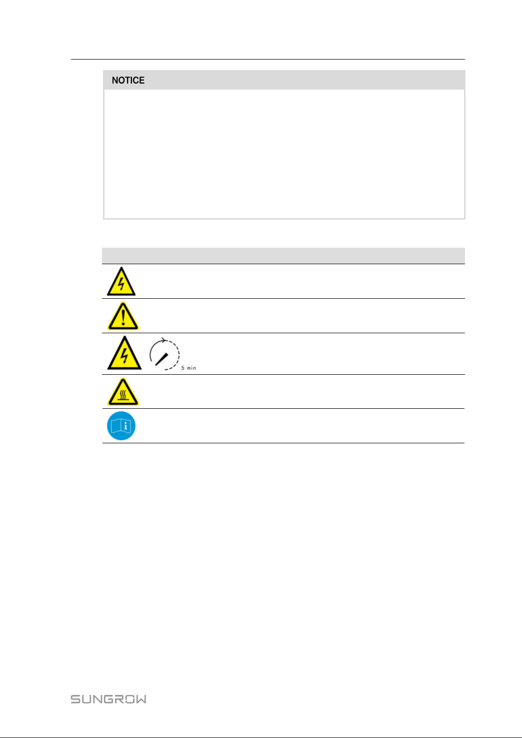
WWaarrnniinnggLLaabbeell
LLaabbeell
DDeessccrriippttiioonn
Dangertolifeduetohighvoltages!
Onlyqualifiedpersonnelcanopenandservicetheinverter.
Disconnecttheinverterfromalltheexternalpowersources
beforeservice!
Donottouchlivepartsuntil5minutesafterdisconnection
fromthepowersources.
Thereisadangerfromahotsurfacethatmayexceed60°C.
Checktheusermanualbeforeservice!
1.4SkillsofQualifiedPersonnel
Allinstallationsshouldbeperformedbyqualifiedpersonnel.Theyshouldhave:
• Trainingintheinstallationandcommissioningoftheelectricalsystem,aswellasthe
dealingwithhazards
• Knowledgeofthemanualandotherrelateddocuments
• Knowledgeofthelocalregulationsanddirectives
3
Page 14
2
ProductIntroduction
2.1IntendedUsage
SG250HX,atransformerlessthree-phasePV grid-connectedinverter,isan integral
componentinthePVpowersystem.
TheinverterisdesignedtoconvertthedirectcurrentpowergeneratedfromthePV
modulesintogrid-compatibleACcurrentandfeedstheACcurrenttotheutilitygrid.The
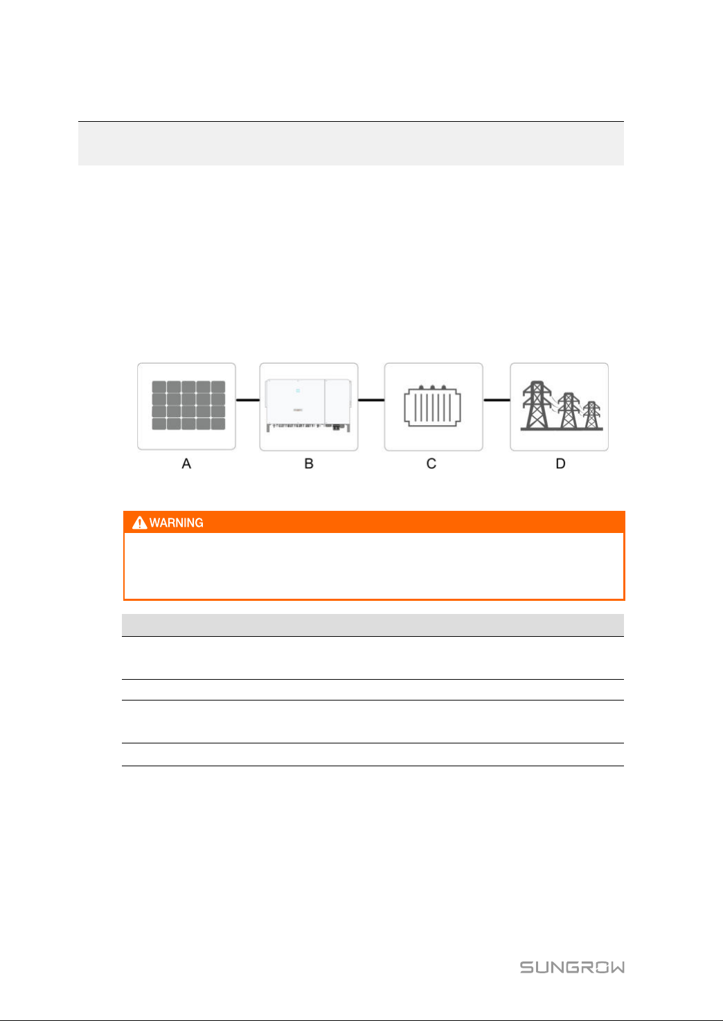
intendedusageoftheinverterisillustratedin
system"
.
InvertercannotconnectthePVstringswhosepositiveandnegativeterminals
needtobegrounded.
DonotconnectanylocalloadbetweentheinverterandtheACcircuitbreaker.
"figure2-1InverterapplicationinPVpower
ffiigguurree22--11InverterapplicationinPVpowersystem
IItteemm
A
BInverterSG250HX
CTransformer
D
4
DDeessccrriippttiioonn
PVstrings
Utilitygrid
NNoottee
Monocrystallinesilicon,polycrystallinesiliconandthin-
filmwithoutgrounding.
Boostthelowvoltagefrominvertertogrid-compatible
mediumvoltage.
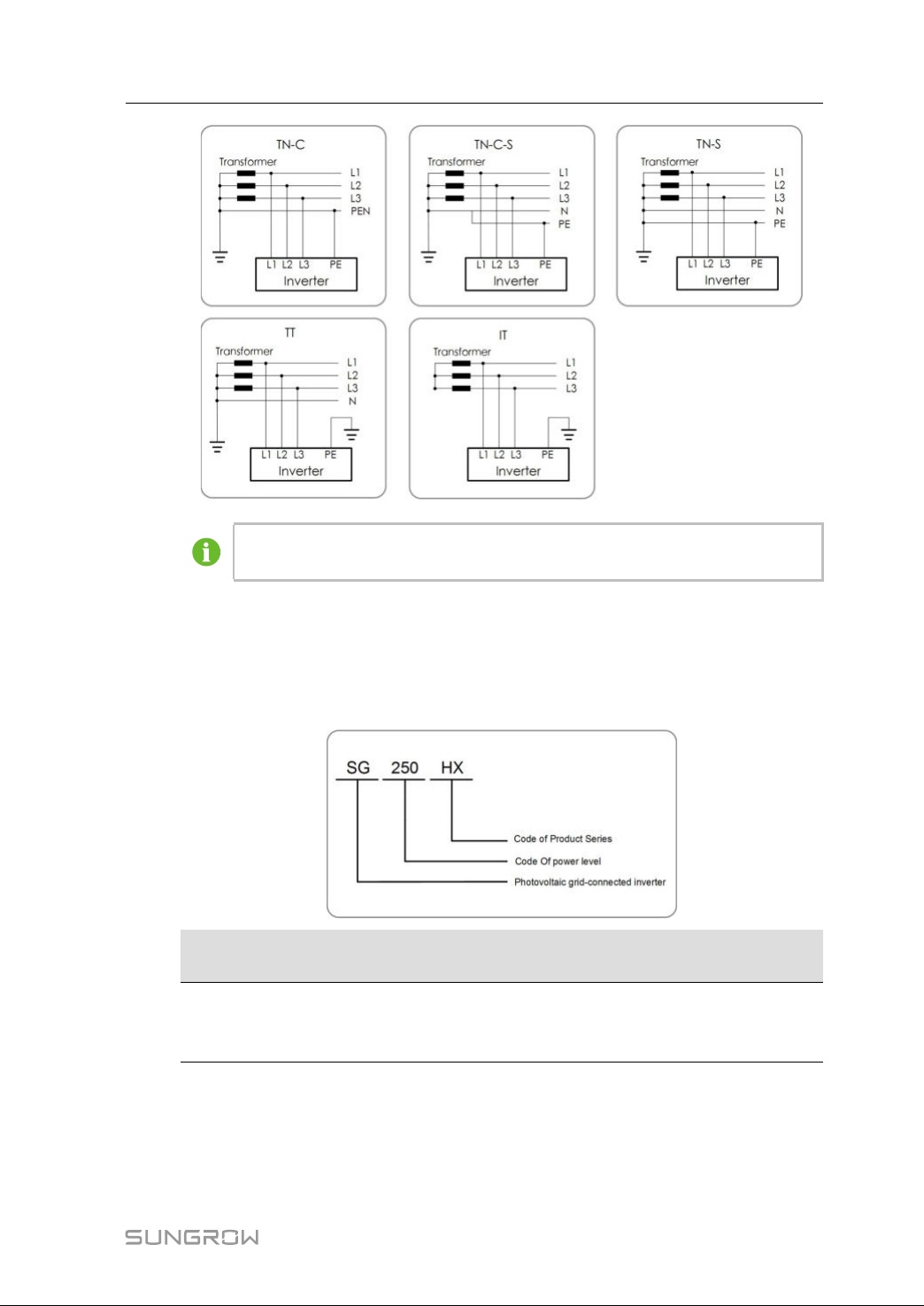
TN-C,TN-S,TN-C-S,TT,IT.
Page 15
UserManual2ProductIntroduction
MakesuretheinverterisappliedtoanITsystembeforeenablingtheAnti-PID
function.
2.2ProductIntroduction
2.2.1 ModelDescription
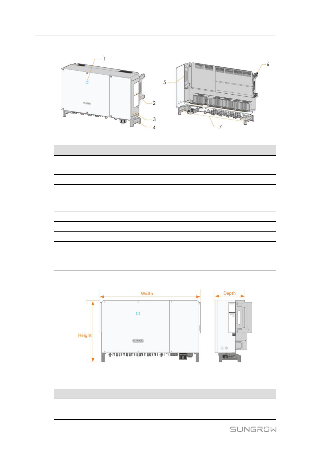
Thedevicemodeldescriptionisasfollows:
MMooddeell
SG250HX
Thedevicemodelcanbefoundonthenameplateattachedtothesideoftheinverter.
Fordetails,referto
NNoommiinnaallOOuuttppuutt
PPoowweerr
250kVA@30℃/
225kVA@40℃/
200KVA@50℃
"3.2IdentifyingtheInverter".
NNoommiinnaallGGrriiddVVoollttaaggee
3/PE,800V
5
Page 16
2ProductIntroductionUserManual
2.2.2 Appearance
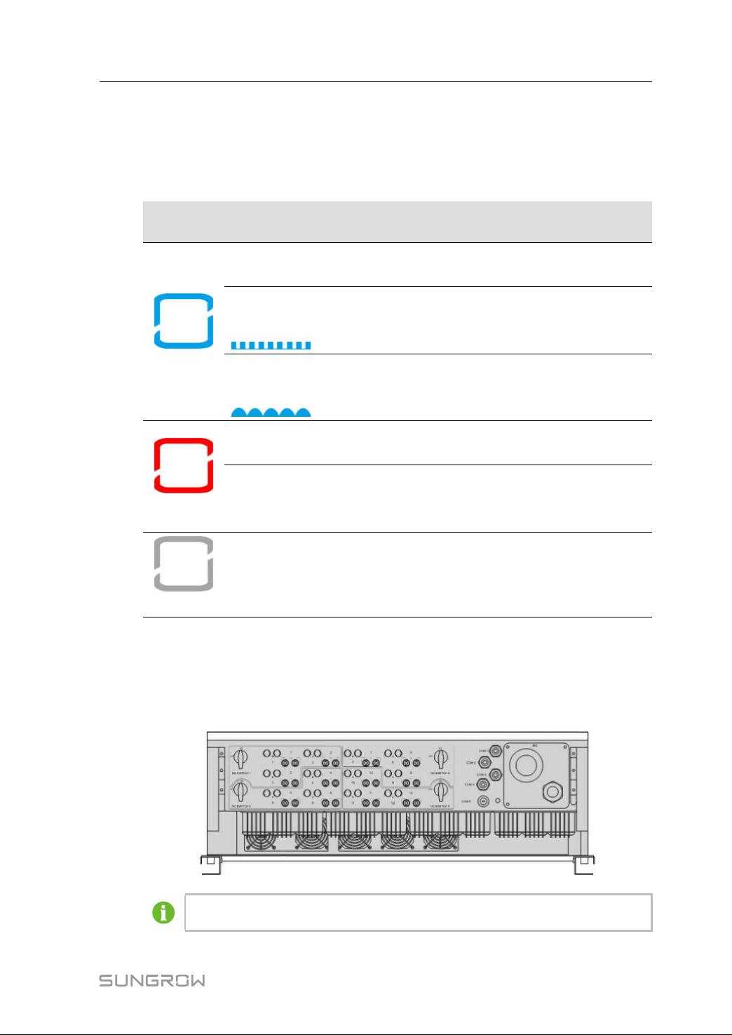
*Theimageshownhereisforreferenceonly.Theactualproductyoureceivemaydiffer.
NNoo..NNaammee
1LEDindicator
panel
2Labels
3Additional
grounding
terminals
4Bottomhandles2,usedtomovetheinverter.
5
Sidehandles
6Mountingears4,usedtohangtheinverterontothemounting-bracket.
7
Wiringarea
2.2.3 Dimensions
DDeessccrriippttiioonn
HMIinterfacetoindicatethepresentworkingstateof
theinverter.
Warningsymbols,nameplate,andQRcode.
2,useatleastoneofthemtogroundtheinverter.
2,usedtomovetheinverter.
DCswitches,ACterminals,DCterminals,and
communicationterminals.
Fordetails,referto
"5.2TerminalDescription".
ffiigguurree22--22DimensionsoftheInverter
*Theimageshownhereisforreferenceonly.Theactualproductyoureceivemaydiffer.
DDiimmeennssiioonnss((WW**HH**DD))WWeeiigghhtt
1051*660*363mm
99kg(218.3lb)
(41.4''*26''*14.3'')
6
Page 17
UserManual2ProductIntroduction
2.2.4 LEDIndicatorPanel
AsanHMI,theLEDindicatorpanelonthefrontoftheinvertercanindicatethepresent
workingstateoftheinverter.
table2-1LEDindicatordescription
LLEEDD
iinnddiiccaattoorr
Blue
Red
OFF
LLEEDDssttaatteeDDeeffiinniittiioonn
Thedeviceisconnectedtothegridandoperating
ON
Fastblink
(Period:0.2s)
normally.
TheBluetoothcommunicationisconnectedand
thereisdatacommunication.
Nosystemfaultoccurs.
Slowflash
Thedeviceisinstandbyorstartupstate(not
(Period:2s)
feedingpowerintothegrid).
Afaultoccursandthedevicecannotconnectto
ON
thegrid
TheBluetoothcommunicationisconnectedand
Twinkling
thereisdatacommunication.
Systemfaultoccurs.
OFF
BoththeACandDCsidesarepowereddown.
2.2.5 DCSwitch
TheDCswitchisusedtodisconnecttheDCcurrentsafelywhenevernecessary.
TheinverterisequippedwithfourDCswitches,eachDCswitchcontrolsits
correspondingDCterminals.
TurntheDCswitchestotheONpositionbeforerestartingtheinverter.
7
Page 18
2ProductIntroductionUserManual
2.3CircuitDiagram
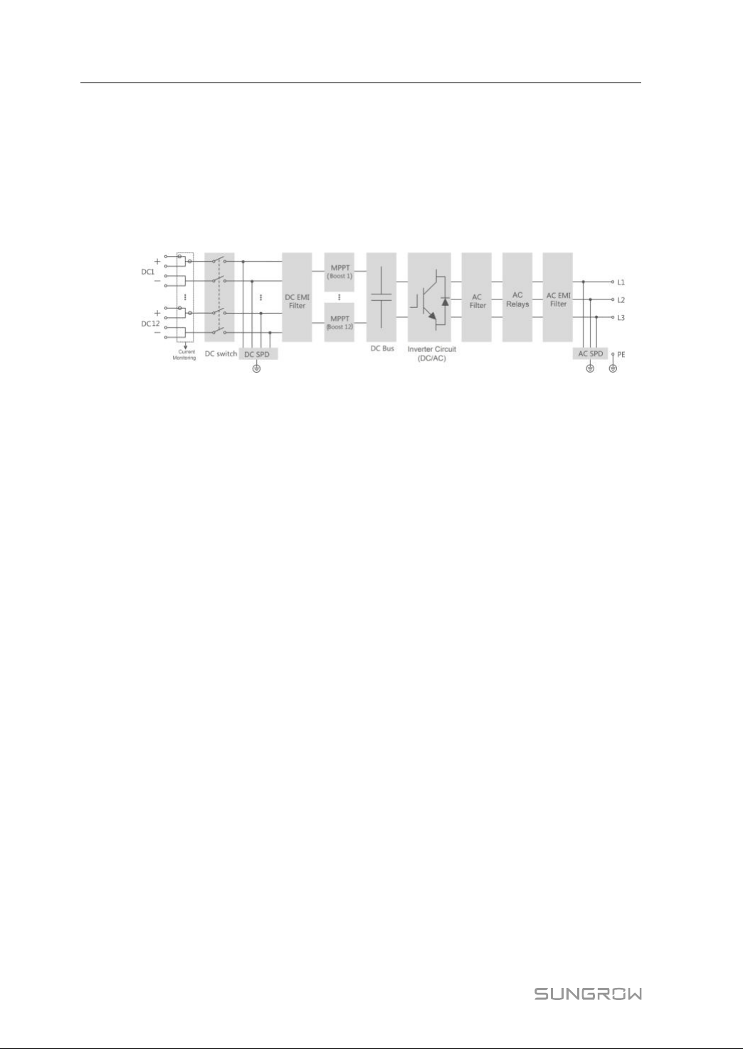
TheMPPTisutilizedforDCinputtoensurethemaximumpowerfromthePVarrayat
differentPVinputconditions.TheinversioncircuitconvertstheDCpowerintoACpower
andfeedstheACpowerintotheutilitygridthroughtheACterminal.Theprotection
circuitisequippedtoensurethesafeoperationofthedeviceandpersonalsafety.
Thefollowingfigureshowsthemaincircuitoftheinverter.
ffiigguurree22--33Circuitdiagram
2.4FunctionDescription
Theinverterisequippedwiththefollowingfunctions:
CCoonnvveerrssiioonnffuunnccttiioonn
TheinverterconvertstheDCcurrentintogrid-compatibleACcurrentandfeedstheAC
currentintothegrid.
DDaattaassttoorraaggee
Theinverterlogsrunninginformation,errorrecords,etc.
PPaarraammeetteerrccoonnffiigguurraattiioonn
Theinverterprovidesvarioussettableparameters.Userscansetparametersviathe
Apptomeettherequirementsandoptimizetheperformance.
CCoommmmuunniiccaattiioonniinntteerrffaaccee
TheinverterisdesignedwithstandardRS485communicationinterfaces.
ThestandardRS485communicationinterfacesareusedtoestablishcommunication
connectionwithmonitoringdevicesanduploadmonitoringdatabyusing
communicationcables.
Aftercommunicationconnectionisestablished,userscanviewinverterinformationor
setinverterparametersthroughtheiSolarCloud.
PPrrootteeccttiioonnFFuunnccttiioonn
Theprotectivefunctionsareintegratedintheinverter,includinganti-islandprotection,
LVRT/ZVRT,DCreversedpolarityprotection,ACshortcircuitprotection,leakagecurrent
protection,DCovervoltage/overcurrentprotection,etc.
PPIIDDffuunnccttiioonn
AfterthePIDfunctionisenabled,thevoltagetogroundofallPVmodulesisgreaterthan
0,thatis,thePVmodule-to-groundvoltageisapositivevalue.
8
Page 19
UserManual2ProductIntroduction
• BeforeenablingthePIDrecoveryfunction,makesurethevoltagepolarityof
thePVmodulestogroundmeetsrequirement.Ifthereareanyquestions,
contactthePVmodulemanufacturerorreaditscorrespondingusermanual.
• IfthevoltageschemeforthePIDprotection/recoveryfunctiondoesnotmeet
therequirementofcorrespondingPVmodules,thePIDfunctionwillnotwork
asexpectedorevendamagethePVmodules.
• Anti-PIDfunction
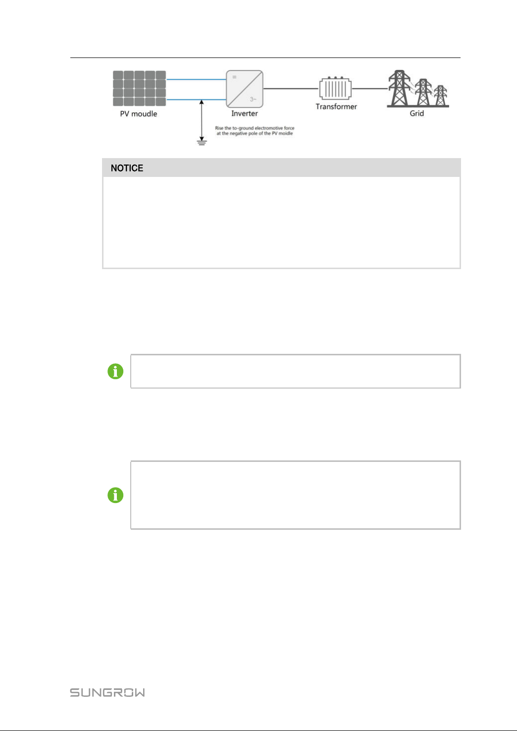
Whentheinverterisrunning,thePIDfunctionmodulerisesthepotentialbetweenthe
negativepoleofthePVarrayandthegroundtoapositivevalue,tosuppressthePID
effect.
MakesuretheinverterisappliedtoanITsystembeforeenablingtheanti-PID
function.
• PIDrecoveryfunction
Whentheinverter isnot running,thePID modulewill applyinverse voltageto PV
modules,torestorethedegradedmodules.
• IfthePIDrecoveryfunctionisenabled,itonlyworksatnight.
• AfterthePIDrecoveryfunctionisenabled,thevoltageofthePVstringto
ground is500Vdc bydefault,andthedefault valuecanbemodified
throughtheApp.
9
Page 20
3
UnpackingandStorage
3.1UnpackingandInspection
Theinverteristhoroughlytestedandstrictlyinspectedbeforedelivery.Damagemaystill
occurduringshipping.Conductathoroughinspectionafterreceivingthedevice.
• Checkthepackingforanyvisibledamage.
• Checktheinnercontentsfordamageafterunpacking.
• Checkthedeliveryscopeforcompletenessaccordingtothepackinglist.
ContactSUNGROWorthesupplierincasethereisanydamageorincompleteness.
Donotdisposeoftheoriginalpackingcase.Itisrecommendedtostoretheinverterinit.
3.2IdentifyingtheInverter
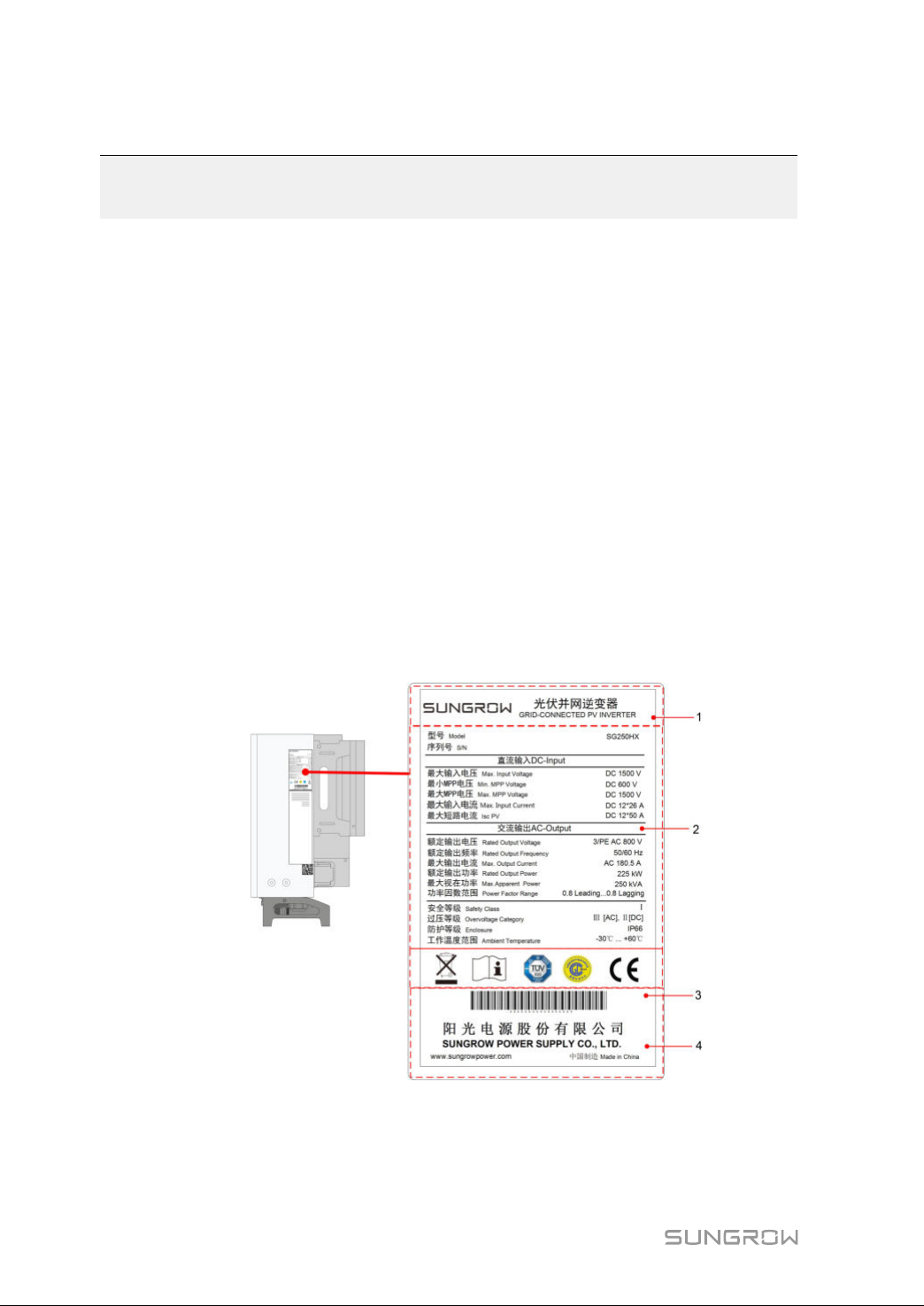
Thenameplatecanbefoundonboththeinverterandthepackingcase.Itprovides
informationontypeofinverter,importantspecifications,marksofcertification
institutions,andserialnumberwhichareavailableandidentifiedbySUNGROW.
10
ffiigguurree33--11NameplateofInverters
*Theimageshownhereisforreferenceonly.Theactualproductyoureceivemaydiffer.
Page 21
UserManual3UnpackingandStorage
IItteemm
1
DDeessccrriippttiioonn
SUNGROWlogoandproducttype
2Technicaldataofinverter
3
4
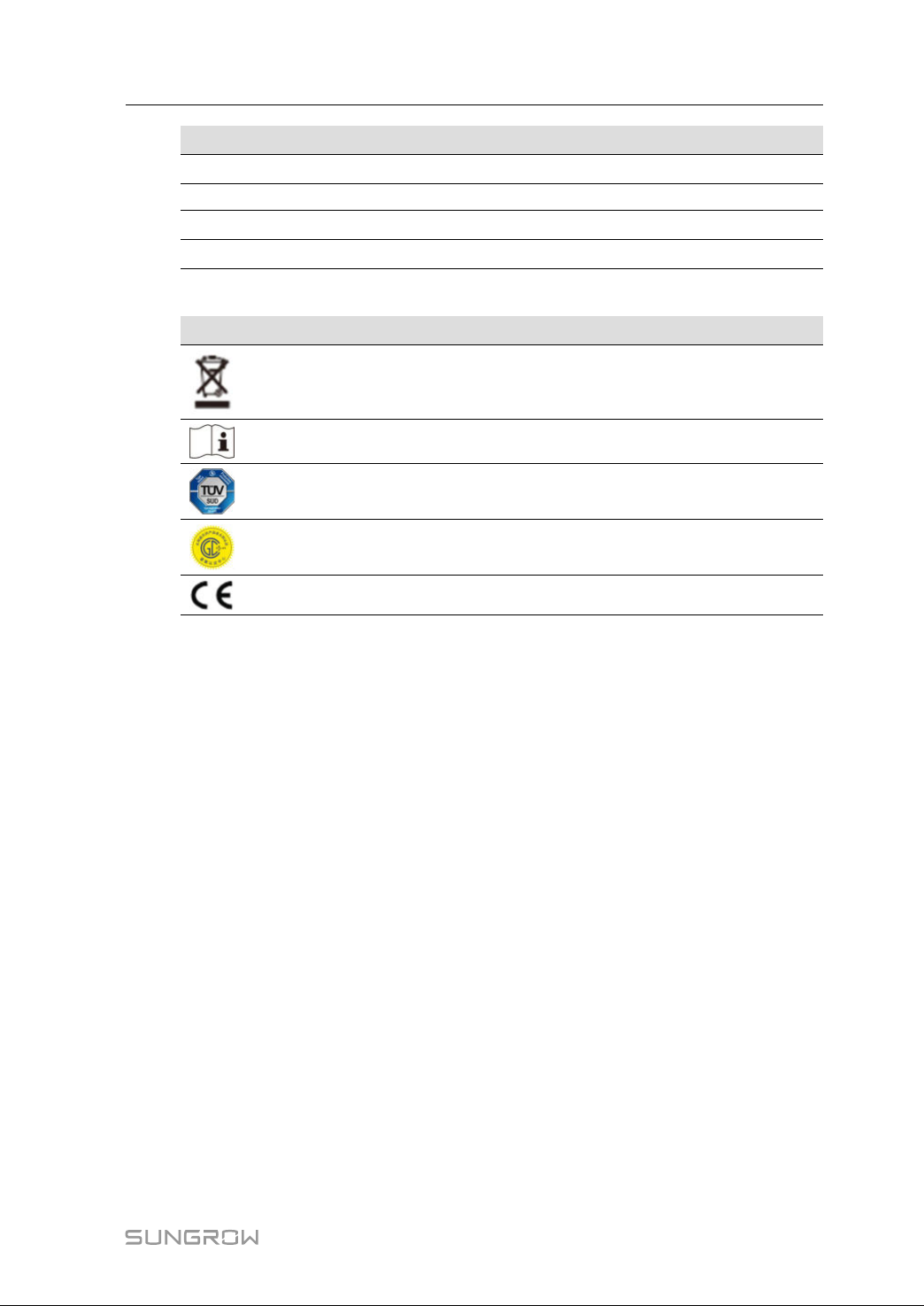
table3-1DescriptionofIconsontheNameplate
IIccoonn
Instructionsandmarksofconformity
Companyname,websiteandcountryofmanufacture
DDeessccrriippttiioonn
Donotdisposeoftheinvertertogetherwithhouseholdwaste.
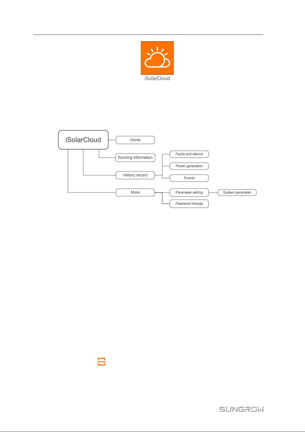
Refertothecorrespondinginstructions.
TÜVmarkofconformity.
CGC-SOLARmarkofconformity.
CEmarkofconformity.
11
Page 22
3UnpackingandStorageUserManual
3.3ScopeofDelivery
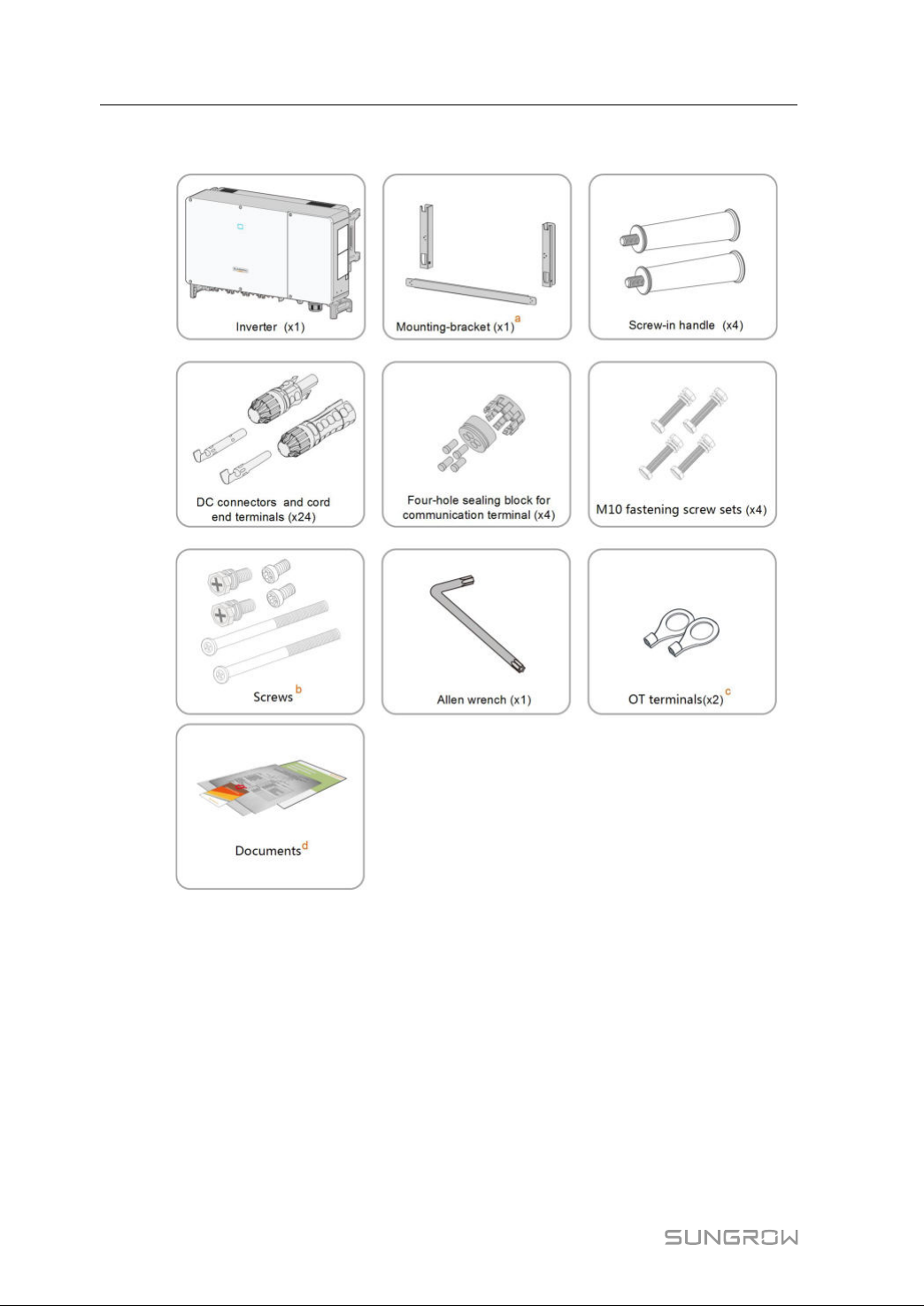
a.Themounting-bracketincludes2mounting-bracketcomponentsand1connecting
bar.
b.ThescrewsincludetwoM4×10,twoM6×65,andtwoM6×12hexsocketscrews.
c.ThetwoOTterminalsareusedforwiringpowercableofthetrackingsystem,where
thewiringrangeis4–6mm
d.Thedocumentsincludethequickinstallationguide,packinglist,warrantycard,etc.
3.4InverterStorage
Properstorageisrequirediftheinverterisnotinstalledimmediately.
12
ffiigguurree33--22ScopeofDelivery
2
.
Page 23
UserManual3UnpackingandStorage
• Storetheinverterintheoriginalpackingcasewiththedesiccantinside.
• Thestoragetemperaturemustbealwaysbetween-40°Cand+70°C,andthe
storagerelativehumiditymustbealwaysbetween0and95%,non-condensing.
• Incaseofstackingstorage,thenumberofstackinglayersshouldneverexceedthe
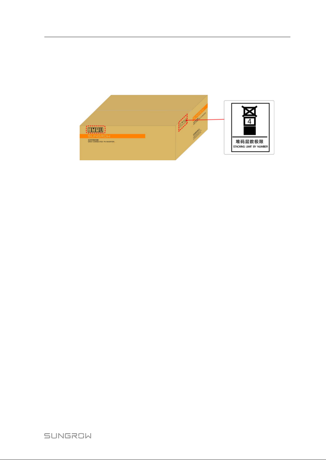
limitmarkedontheoutersideofthepackingcase.
• Thepackingcaseshouldbeupright.
• Iftheinverterhasbeenstoredmorethanhalfayear,thequalifiedpersonnelshould
thoroughlycheckandtestitbeforeusing.
13
Page 24
4
MechanicalMounting
4.1SafetyduringMounting
Makesurethereisnoelectricalconnectionbeforeinstallation.
Inordertoavoidelectricshockorotherinjury,besurethereisnoelectricityor
plumbinginstallationsbeforedrillingholes.
Riskofinjuryduetoimproperhandling
• Alwaysfollowtheinstructionswhenmovingandpositioningtheinverter.
• Improperoperationmaycauseinjuries,seriouswounds,orbruise.
Systemperformancelossduetopoorventilation!
• Keeptheheatsinksuncoveredtoensureheatdissipationperformance.
4.2LocationRequirements
Selectanoptimalmountinglocationforsafeoperation,longservicelife,and
outstandingperformance.
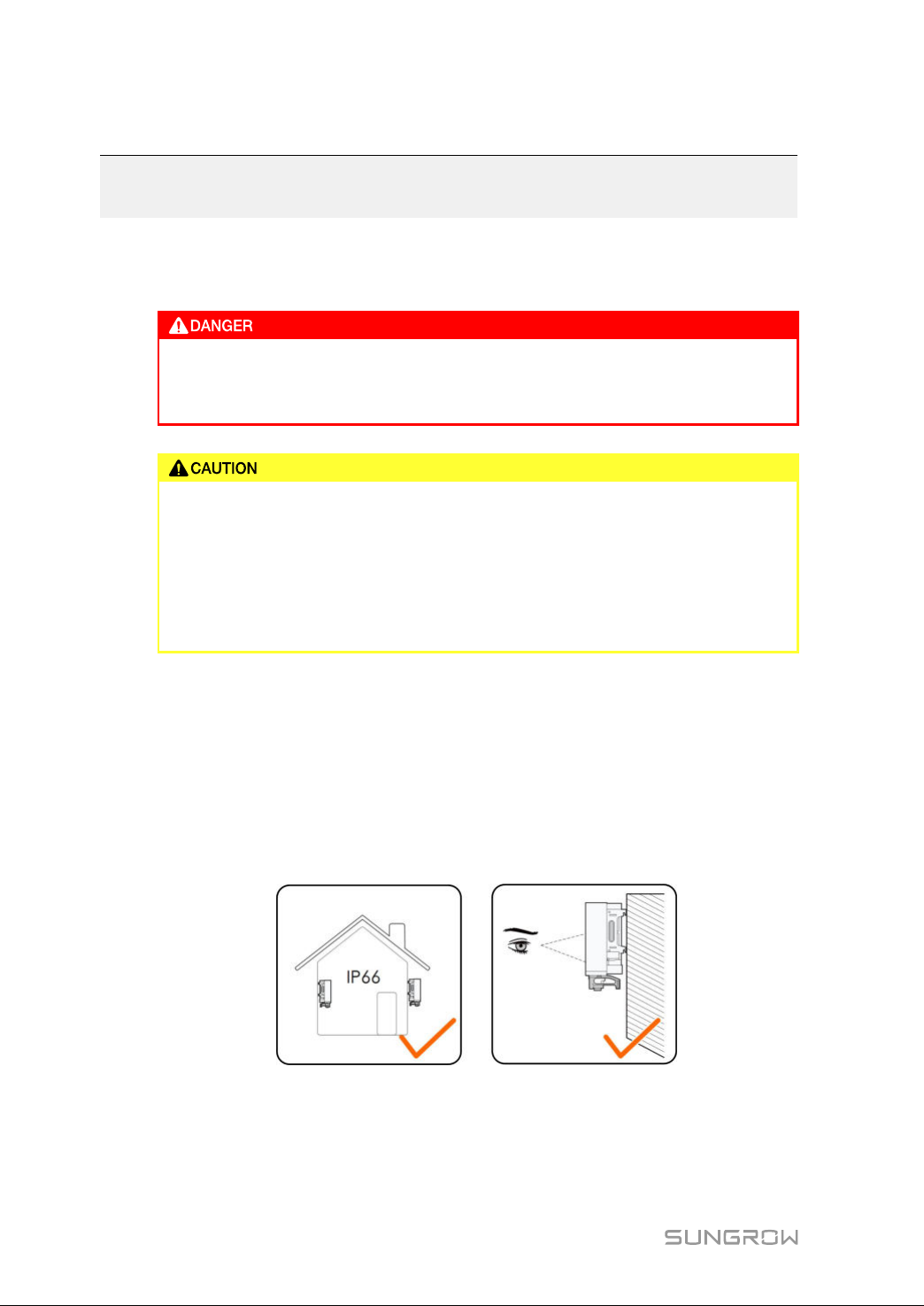
• TheinverterwithIP66canbeinstalledbothindoorsandoutdoors.
• Installtheinverterinaplaceconvenientforelectricalconnection,operation,and
maintenance.
4.2.1 InstallationEnvironmentRequirements
• Theinstallationenvironmentisfreeofinflammableorexplosivematerials.
• Thelocationshouldbenotaccessibletochildren.
14
Page 25
UserManual4MechanicalMounting
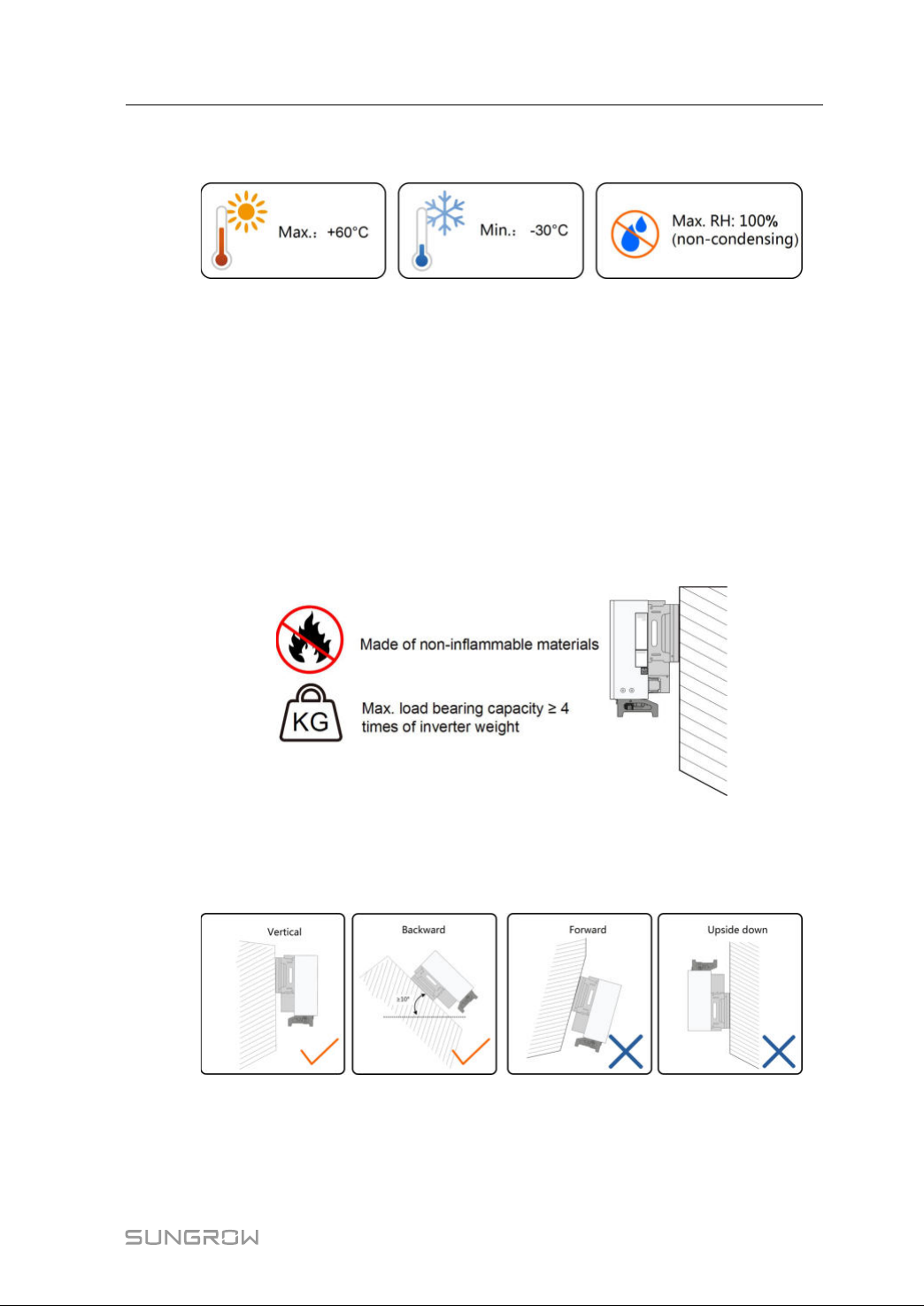
• Theambienttemperatureandrelativehumiditymustmeetthefollowing
requirements.
• Donotinstalltheinverteroutdoorsinareaswithsaltdamage,whichmainlyreferto
theareaswithin500mawayfromthecoast.Thedepositionofsaltfogvarieslargely
with nearby seawatercharacteristics, sea wind,precipitation, relative humidity,
terrain,andforestcoverage.
• Preventtheinverterfromdirectexposuretosun,rainandsnow.
• Theinvertershouldbewellventilated.Ensureaircirculation.
• Neverinstalltheinverter inlivingareas. Theinverter willgeneratenoise during
operation,affectingdailylife.
4.2.2 CarrierRequirements
Theinstallationcarriershouldmeetthefollowingrequirements:
4.2.3 InstallationAngleRequirements
Inverterverticallyorataminimumbacktiltof10°.Forwardinstallationorupsidedown
installationisprohibited.
15
Page 26
4MechanicalMountingUserManual
Incasetheinstallationsiteisalevelsurface,mounttheinvertertothe
horizontal-mountingbrackettomeetthemountinganglerequirements,as
showninthefigurebelow.
Takethefollowingitemsintoaccountwhendesigningthebracketscheme:
• Consideronsite climateconditions andtakeanti-snow andanti-rain
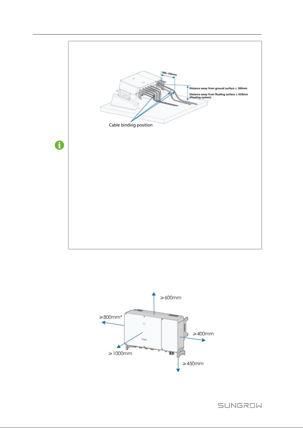
measuresifnecessary.
• Ensurethatthewaterproofconnectorsareatleast300mmhigherthanthe
groundsurface.Incasetheinverterisappliedinafloatingpowerplant,
ensurethatthewaterproofconnectorsareatleast650mmhigherthanthe
floatingbodysurface.
• Bindthecablesatthepositions300~350mmawayfromtheDCconnector,
ACwaterproofterminal,andcommunicationwaterproofterminal.
• Thevariouswaterproofterminalsshouldbetightenedinaccordancewith
thetorquerequirementsinthismanualtoensurethattheyaretightand
sealed.
ContactSUNGORWifyouhaveanyquestion.
4.2.4 InstallationClearanceRequirements
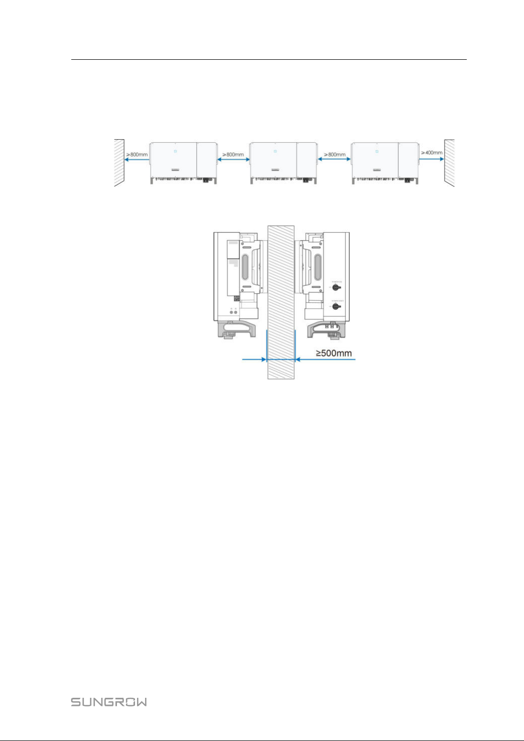
• Reserveenoughclearancearoundtheinvertertoensuresufficientspaceforheat
dissipation.(Thefansaremaintainedontheleftsideoftheinverter,andalarger
clearanceisrequired.)
16
Page 27
UserManual4MechanicalMounting
*Thedistancecanbeshortenedto200mmaccordingtoonsiteconditions.Incase
thedistanceislessthan800mm,movetheinverterfromthemounting-bracketor
wallbeforemaintainingfans.
• Incaseofmultipleinverters,reservespecificclearancebetweentheinverters.
• Incaseofback-to-backinstallation,reservespecificclearancebetweenthetwo
inverters.
• InstalltheinverteratanappropriateheightforeaseofviewingLEDindicatorsand
operatingswitches.
17
Page 28
4MechanicalMountingUserManual
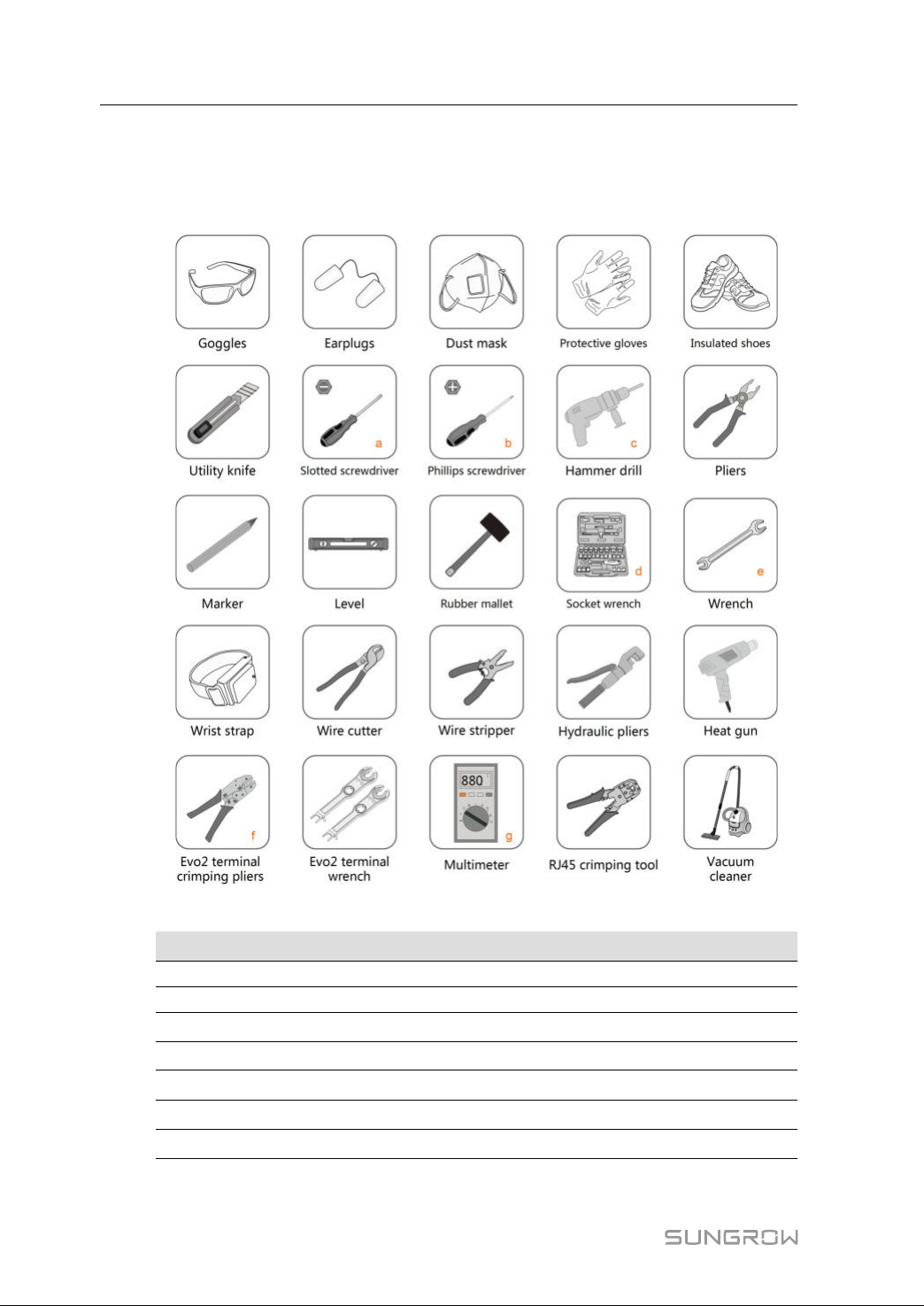
4.3InstallationTools
Installationtools includebutarenotlimitedtothefollowing recommendedones.If
necessary,useotherauxiliarytoolsonsite.
18
table4-1Toolspecification
NNoo..
a
SSppeecciiffiiccaattiioonn
M2/M6
bM4/M6/M8
c
d
e
f
g
Drillbit:φ12,φ14
Includessleevewithopeningsize16mm
Opening:13,16mm
Crimprange4~6mm
Range≥1500Vdc
2
Page 29
UserManual4MechanicalMounting
4.4MovingtheInverter
Movetheinvertertothespecifiedpositionbeforeinstallation.Theinvertercanbemoved
manuallyorviaahoist.
4.4.1 ManualTransport
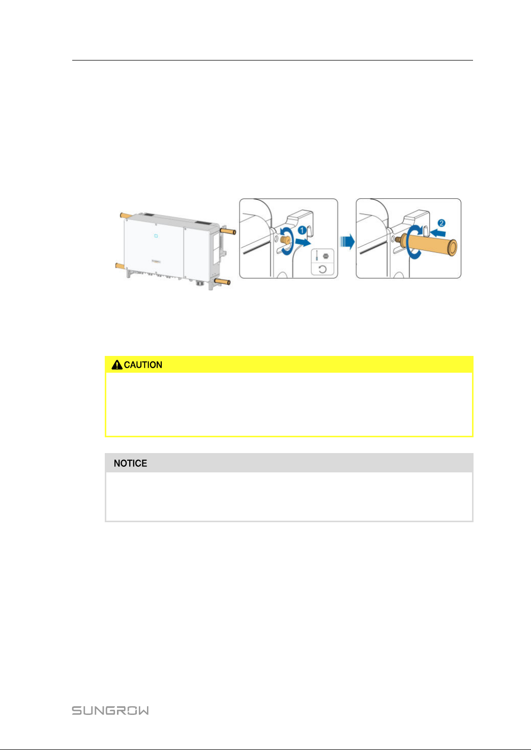
step1Releasethesealingscrewsonthemountingearswithaflat-headscrewdriverandstore
themproperly.Anchorthefoursuppliedscrew-inhandlestothemountingearsand
baseoftheinverter.
step2Liftandmovetheinvertertothedestinationbyusingthesideandbottomhandlesas
wellasthefourinstalledhandles.
step3Removethescrew-inhandlesandreassemblethesealingscrewsreleasedinStep1.
Inappropriatemovingoperationmaycausepersonalinjury!
Itisrecommendedthatatleastfourinstallerscarrytheinvertertogetherand
wearprotectiveequipmentsuchassmash-proofshoesandgloves.
Alwaysbewareofthegravitycenteroftheinverterandavoidtipping.
Thegroundsurfaceonwhichtheinverteristobeplacedshouldbecoveredwith
aspongepad,foamcushionortheliketopreventtheinverterbottomfrom
scratches.
----EEnndd
4.4.2 HoistingTransport
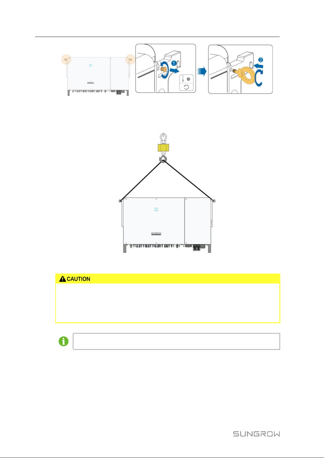
step1Releasethesealingscrewsonthemountingearsandstorethemproperly.Anchortwo
M12threadliftingringstothehangersoftheinverter.
19
Page 30
4MechanicalMountingUserManual
step2Leadtheslingthroughthetwoliftingringsandfastenthetie-downstrap.
step3Hoisttheinverter,andstoptocheckforsafetywhentheinverteris100mmabovethe
ground.Continuehoistingthedevicetothedestinationafterensuringthesafety.
step4RemovetheliftingringsandreassemblethesealingscrewsreleasedinStep1.
Keeptheinverterbalancedthroughoutthehoistingprocessandavoidcollisions
withwallsorotherobjects.
Stophoistingintheeventofsevereweather,suchasheavyrain,thickfog,or
strongwind.
Theliftingringsandtheslingarenotwithinthedeliveryscope.
----EEnndd
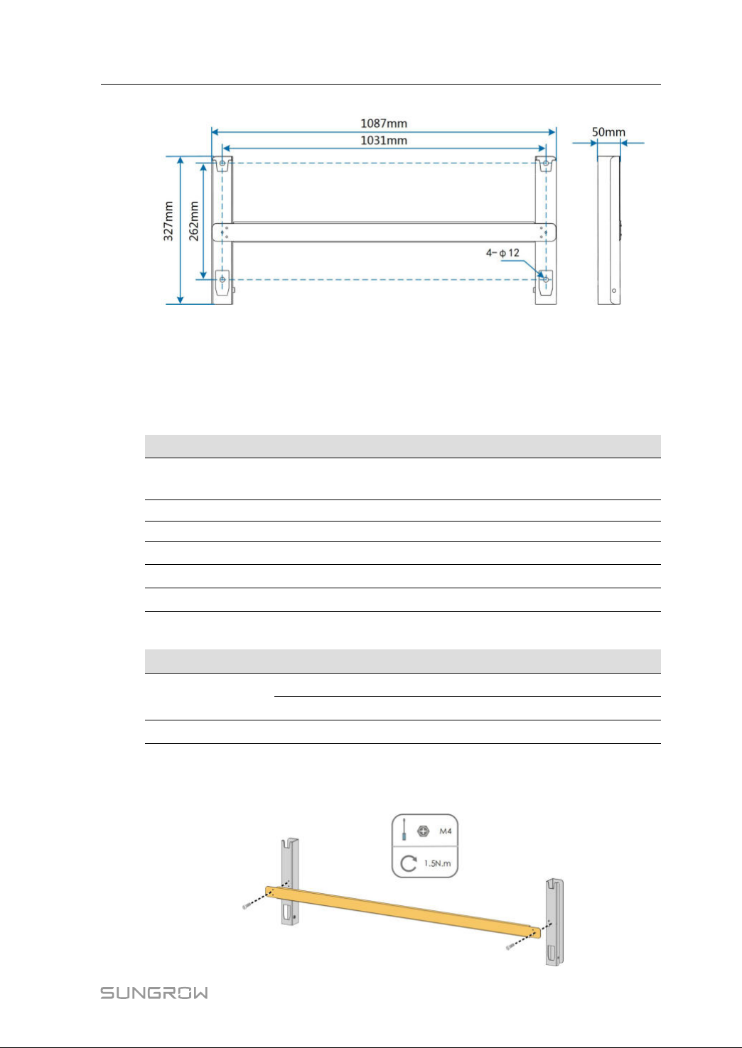
4.5Dimensionsofmounting-bracket
Dimensionsoftheassembledmounting-bracketareasfollows:
20
Page 31
UserManual4MechanicalMounting
ffiigguurree44--11Dimensionsofmounting-bracket
4.6PVBracket-MountedInstallation
4.6.1 PreparationbeforeMounting
TToooollss
IItteemm
Phillipsscrewdriver/electric
screwdriver
Marker
Level
Hammerdrill
Socketwrench
wrench
SSppaarreeppaarrttss
IItteemm
Grubscrew
Boltassembly
QQuuaannttiittyySSppeecciiffiiccaattiioonn
2M4×10
2M6×65
4M10
SSppeecciiffiiccaattiioonn
M4,M6
-
-
Drillbit:φ12
Including16mmsocket
Opening:16mm
4.6.2 MountingSteps
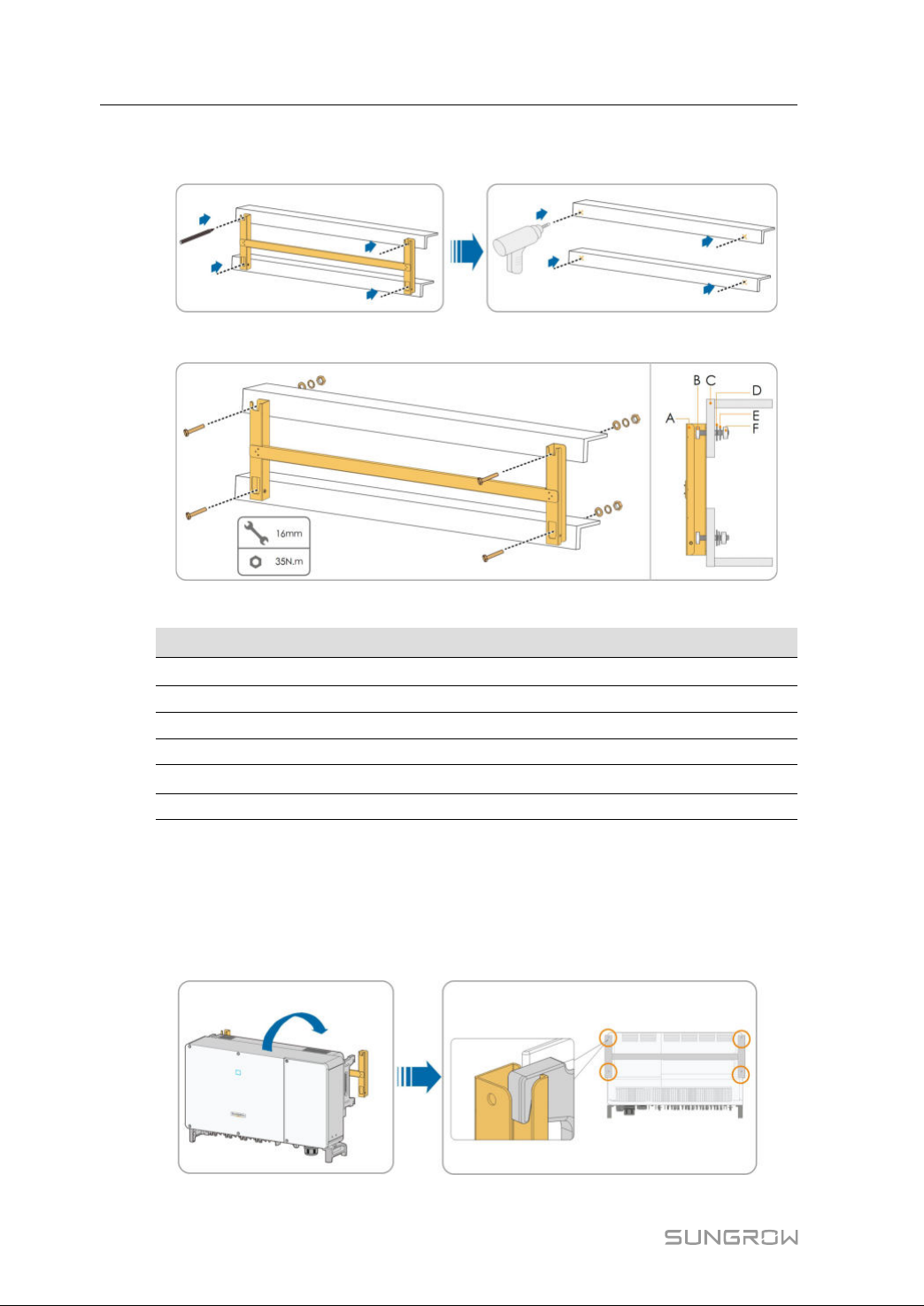
step1Assemblethemounting-bracketbyusingtheconnectingbar.
SSoouurrccee
Deliveryscope
Deliveryscope
Deliveryscope
21
Page 32
4MechanicalMountingUserManual
step2Leveltheassembledmounting-bracketbyusingthelevel,andmarkthepositionsfor
drillingholesonthePVbracket.Drilltheholesbyusingahammerdrill.
step3Securethemounting-bracketwithbolts.
table4-2Fasteningsequence
NNoo..
A
CCoommppoonneennttssDDeessccrriippttiioonn
Mounting-bracket
-
BFullthreadedboltM10*45
CMetalbracket
DFlatwasher
E
Springwasher
-
-
-
FHexnutsM10
step4Takeouttheinverterfromthepackingcase.
step5Hoisttheinvertertotheinstallationpositionwhennecessary(referto
Transport"
).Iftheinstallationpositionisnothighenough,skipperformingthisstep.
"4.4.2Hoisting
step6Hangtheinvertertothemounting-bracketandensurethatthemountingearsperfectly
engagewiththemounting-bracket.
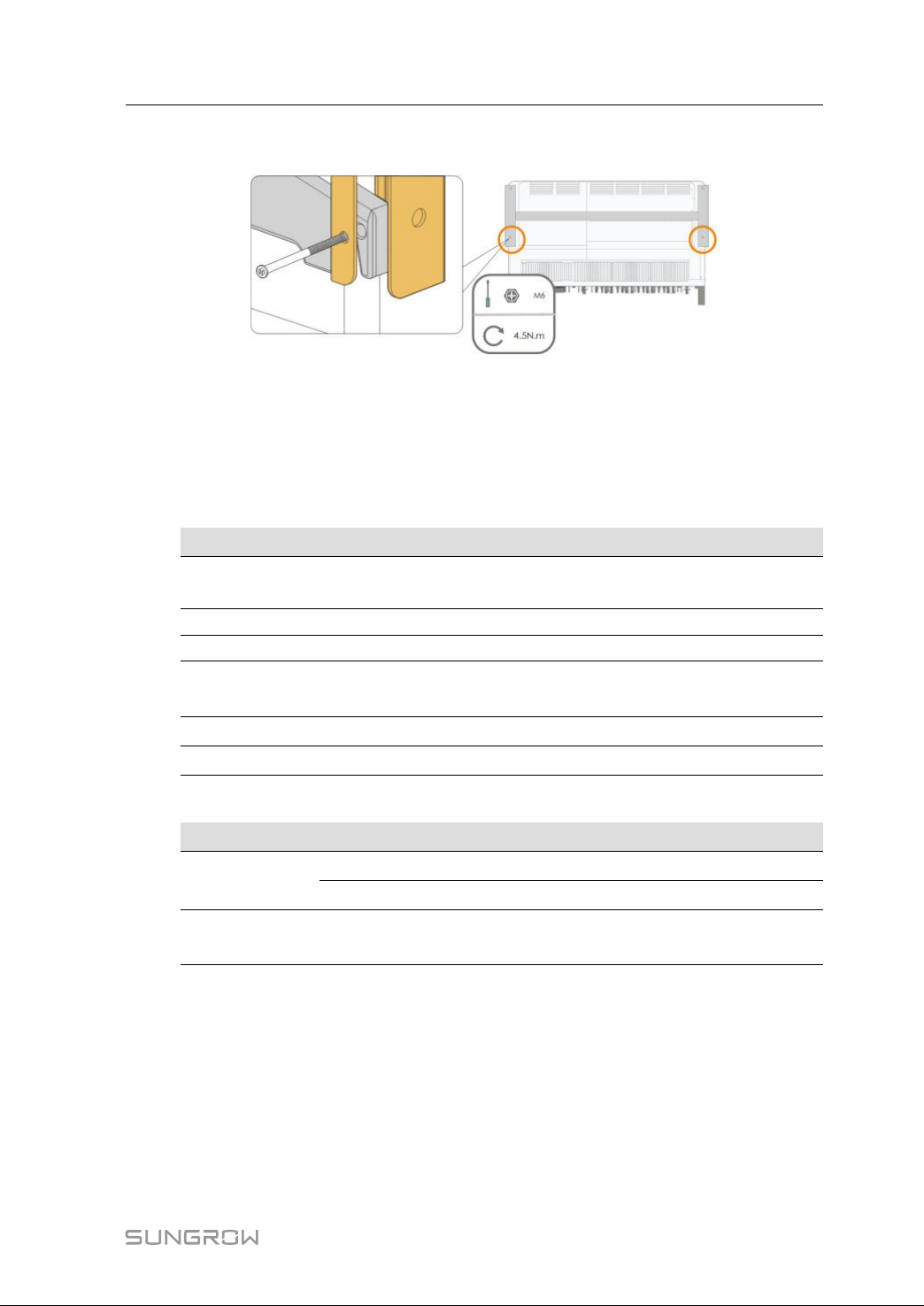
22
Page 33
UserManual4MechanicalMounting
step7FixtheinverterwithtwoM6×65screws.
----EEnndd
4.7Wall-MountedInstallation
4.7.1 PreparationbeforeMounting
TToooollss
IItteemm
Phillipsscrewdriver/electric
screwdriver
Marker
Level
Hammerdrill
Socketwrench
Wrench
SSppaarreeppaarrttss
IItteemm
Grubscrew
Expansionbolts
QQuuaannttiittyySSppeecciiffiiccaattiioonn
2M4×10
2M6×65
4
SSppeecciiffiiccaattiioonn
M4,M6
-
-
Drillbit(Selectaccordingtoexpansionbolt
specifications)
Including16mmsocket
Opening:16mm
M10×95
(Recommended)
4.7.2 MountingSteps
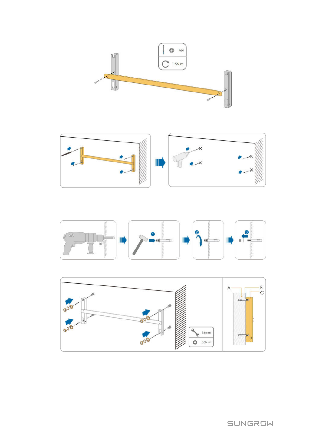
step1Assemblethemounting-bracketbyusingtheconnectingbar.
SSoouurrccee
Deliveryscope
Deliveryscope
Self-prepared
23
Page 34
4MechanicalMountingUserManual
step2Leveltheassembledmounting-bracketbyusingthelevel,andmarkthepositionsfor
drillingholesontheinstallationsite.
step3Inserttheexpansionboltsintotheholesandsecurethemwitharubberhammer.Fasten
thenutwithawrenchtoexpandthebolt.Removethenut,springwasher,andflat
washer,andstorethemproperly.
step4Fixthemounting-bracketwiththeexpansionbolts.
24
Page 35
UserManual4MechanicalMounting
table4-3Fasteningsequence
IItteemm
AWall
B
C
DDeessiiggnnaattiioonnDDeessccrriippttiioonn
-
Expansionbolt
Fasteningtheboltinthesequenceofnut,springwasher,
slatwasher
Mounting-
bracket
-
step5Takeouttheinverterfromthepackingcase.
step6Hoisttheinvertertotheinstallationpositionwhennecessary(referto
Transport"
).Iftheinstallationpositionisnothighenough,skipperformingthisstep.
"4.4.2Hoisting
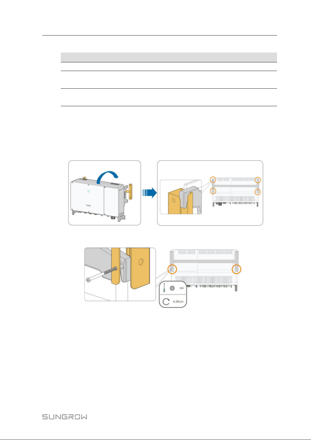
step7Hangtheinvertertothemounting-bracketandensurethatthemountingearsperfectly
engagewiththemounting-bracket.
step8Fixtheinverterwithscrews.
----EEnndd
25
Page 36
5
ElectricalConnection
5.1SafetyInstructions
Priortoanyelectrical connections,keepin mindthatthe inverterhasdual power
supplies. It is mandatory for thequalified personnel to wear personal protective
equipments(PPE)duringtheelectricalwork.
Dangertolifeduetoahighvoltageinsidetheinverter!
• ThePVstringwillgeneratelethalhighvoltagewhenexposedtosunlight.
• Beforestartingelectricalconnections,disconnect theDCand ACcircuit
breakersandpreventthemfrominadvertentreconnection.
• Ensurethatallcablesarevoltagefreebeforeperformingcableconnection.
• Anyimproperoperationsduringcableconnectioncancausedevicedamage
orpersonalinjury.
• Onlyqualifiedpersonnelcanperformcableconnection.
• All cablesmust beundamaged, firmlyattached, properlyinsulated and
adequatelydimensioned.
ComplywiththesafetyinstructionsrelatedtothePVstringsandtheregulations
relatedtotheutilitygrid.
• Allelectricalconnections mustbe inaccordancewithlocaland national
standards.
• Onlywiththepermissionoftheutilitygrid,theinvertercanbeconnectedto
theutilitygrid.
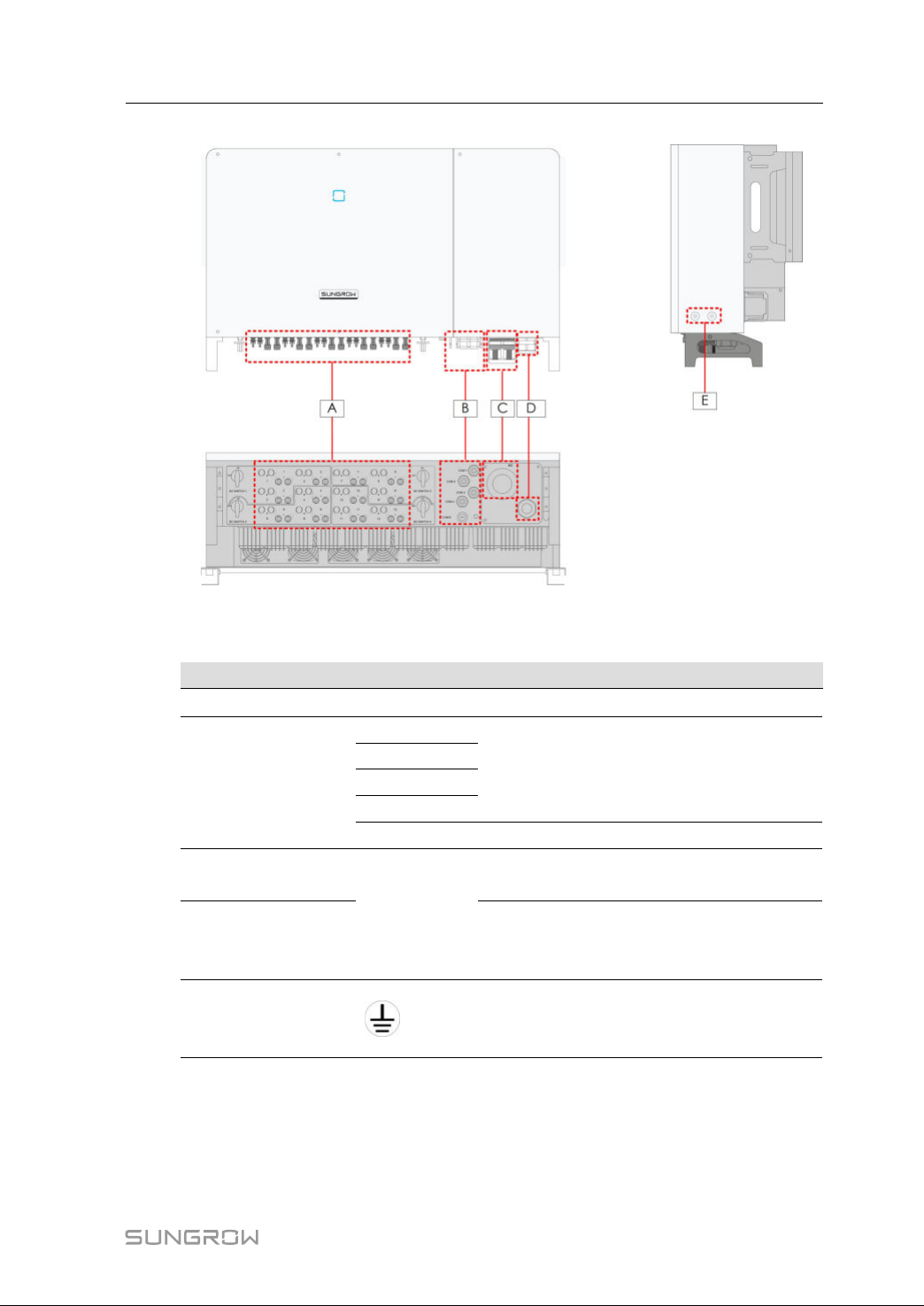
5.2TerminalDescription
Wiringterminalsareatthebottomoftheinverter,asshowninthefigurebelow.
26
Page 37
UserManual5ElectricalConnection
ffiigguurree55--11Wiringterminals
*Figureshownhereisforreferenceonly.Theactualproductyoureceivemaydiffer!
IItteemmTTeerrmmiinnaallMMaarrkkNNoottee
APVterminals+/-
24,PVconnector
COM1
B
Communica-
tionterminal
COM2
COM3
COM4
RS485communication,digitalinput/output
DI/DO,andpowersupplyoftrackingsystem.
COM5Reserved
C
D
ACwiring
terminal
Standby
grounding
AC
UsedforACoutputcableconnection.
Usedforinternalgrounding.
terminal*
Additional
E
grounding
terminal
2,useatleastoneofthemtogroundthe
inverter.
*Ifthe PEcableis anindependentsingle-core cable,itisinsertedintothecabinet
throughthestandbygroundingterminal.
27
Page 38
5ElectricalConnectionUserManual
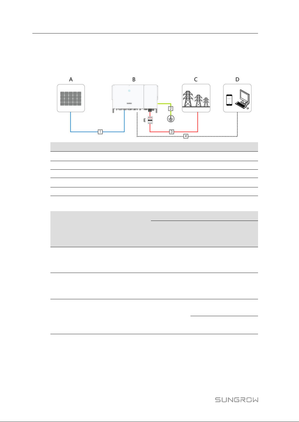
5.3ElectricalConnectionOverview
ElectricalconnectioninthePVsystemincludesadditionalgroundingconnection,AC
connection,andPVstringconnection.
IItteemm
A
DDeessiiggnnaattiioonn
PVstring
BInverter
CGrid
D
Monitoringdevice
EACcircuitbreaker
table5-1Cablerequirements
NNoo..CCaabbllee
TTyyppee
PVcable
1DCcable
complyingwith
1,500Vstandard
Additional
2
Groundin-
gcable
Outdoorsingle-
corecopperwire
cable
Four-corecopper
3ACcable
oraluminum
cable*
SSppeecciiffiiccaattiioonn
CCaabbllee
DDiiaammeetteerr
((mmmm))
CCrroossss--sseeccttiioonnaallaarreeaa
((mmmm22))
4.7~6.44~6
/
Thesameasthatofthe
PEwireintheACcable
L1,L2,L3,(N)wire:
70~240
38~56
PEwire:referto
2PEwirerequirements"
"table5-
28
Page 39
UserManual5ElectricalConnection
SSppeecciiffiiccaattiioonn
NNoo..CCaabbllee
TTyyppee
Three-core
copperor
aluminumcable
andone
independent
single-corePE
CCaabbllee
DDiiaammeetteerr
((mmmm))
Phasecable:
38~56
PEcable:
14~32
CCrroossss--sseeccttiioonnaallaarreeaa
((mmmm22))
L1,L2,L3wire:70~240
PEwire:referto
"table5-
2PEwirerequirements"
cable
Foursingle-core
outdoorcopperor
aluminum
14~32
cables**
Commun-
4
ication
Shieldedtwisted
pair
4.5~181~1.5
L1,L2,L3wire:70~300
PEwire:referto
"table5-
2PEwirerequirements"
cable
*Acoppertoaluminumadapterterminalisrequiredwhenanaluminumcableisused.
Fordetails,referto
"5.6.3AluminiumCableRequirements".
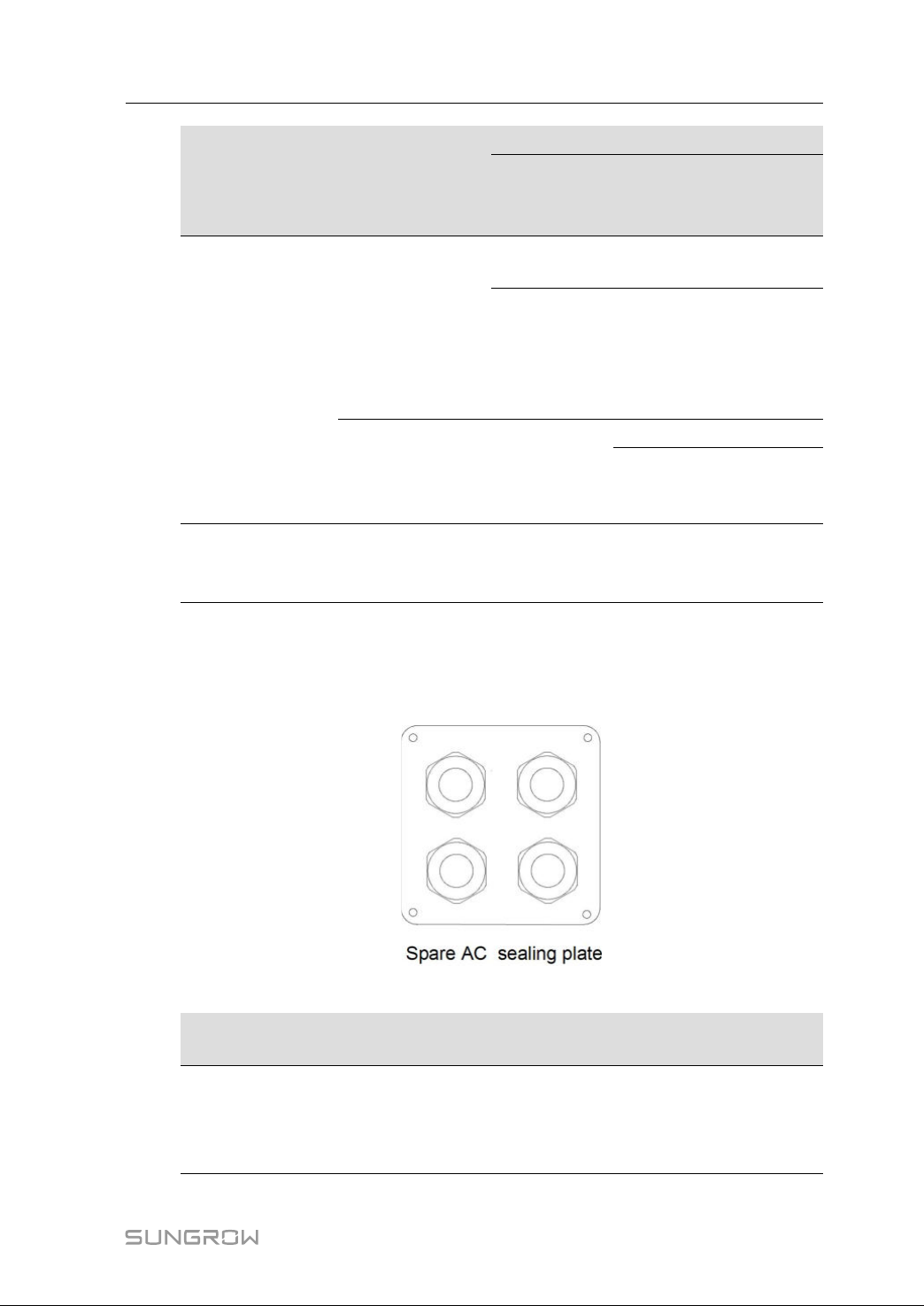
**Ifcaseoffoursingle-corecables,anspareACsealingplateaccessoryisrequired.To
purchasetheACsealingplateaccessory,contactSUNGROW.
table5-2PEwirerequirements
PPEEwwiirreeccrroossss
sseeccttiioonn
S/2
NNoottee
ThespecificationsarevalidonlywhenthephasewireandPE
wireusethesamematerial.Ifotherwise,ensurethatthecross
(S:Phasewire
cross-sectionS)
sectionofthePEwireproducesaconductanceequivalentto
thatofthewirespecifiedinthetable.
29
Page 40

5ElectricalConnectionUserManual
table5-3Powercablefortrackingsystem
SSppeecciiffiiccaattiioonn
CCaabbllee
TTyyppee
CCaabbllee
DDiiaammeett--
eerr((mmmm))
RReeccoommmmeennddeedd
CCrroossss--sseeccttiioonnaall
aarreeaa((mmmm22))
VVoollttaaggeelleevveell
Power
cable
for
tracking
Double-core
outdoor
coppercable
4.5~184~6*
Consistentwith
selectedACcable
system
*Onlywhenthe cablecross-sectional arearanges between4mm
suppliedOTterminalscanbeused.Ifotherwise,usersshouldprepareM12OTterminals
bythemselves,andensurethatthecablecross-sectionalareaiswithintherangeof
0.5–10mm
2
.
5.4AdditionalGroundingConnection
Sincetheinverterisatransformerlessinverter,neitherthenegativepolenorthe
positivepoleofthePVstringcanbegrounded.Otherwise,theinverterwillnot
operatenormally.
Connecttheadditionalgroundingterminaltotheprotectivegroundingpoint
beforeACcableconnection,PVcableconnection,andcommunicationcable
connection.
Thegroundconnectionofthisadditionalgroundingterminalcannotreplacethe
connectionofthePEterminaloftheACcable.Makesurethoesterminalsare
bothgroundedreliably.
5.4.1 AdditionalGroundingRequirements
2
and6mm2,the
Allnon-currentcarryingmetalpartsanddeviceenclosuresinthePVpowersystem
shouldbegrounded,forexample,bracketsofPVmodulesandinverterenclosure.
WhenthereisonlyoneinverterinthePVsystem,connecttheadditionalgrounding
cabletoanearbygroundingpoint.
WhentherearemultipleinvertersinthePVsystem,connectgroundingpointsofall
invertersandthePVarrayframestotheequipotentialcable(accordingtotheonsite
conditions)toimplementanequipotentialconnection.
5.4.2 ConnectionProcedure
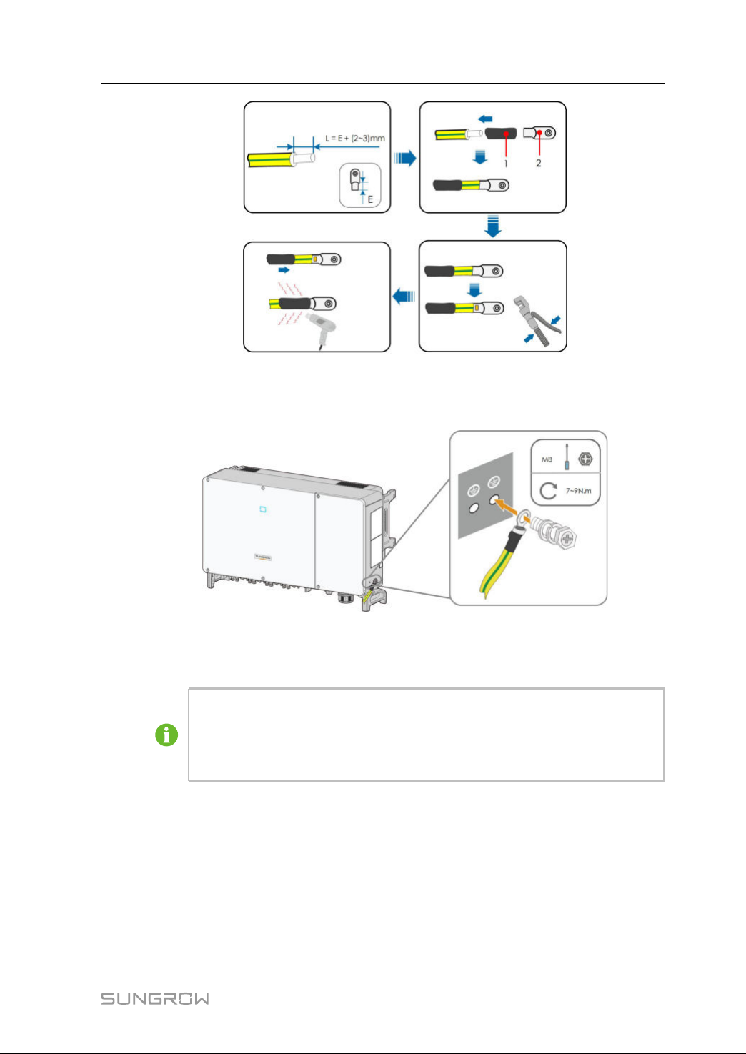
step1PreparethecableandOT/DTterminal.
30
Page 41
UserManual5ElectricalConnection
1:Heatshrinktubing
step2Removethescrewonthegroundingterminalandfastenthecablewithascrewdriver.
step3Applypainttothegroundingterminaltoensurecorrosionresistance.
----EEnndd
Thegroundingscrewshavebeenanchoredtothesideoftheinverterbefore
delivery,anddonotneedtobeprepared.
Therearetwogroundingterminals.Useatleastoneofthemtogroundthe
inverter.
2:OT/DTterminal
5.5OpeningtheWiringCompartment
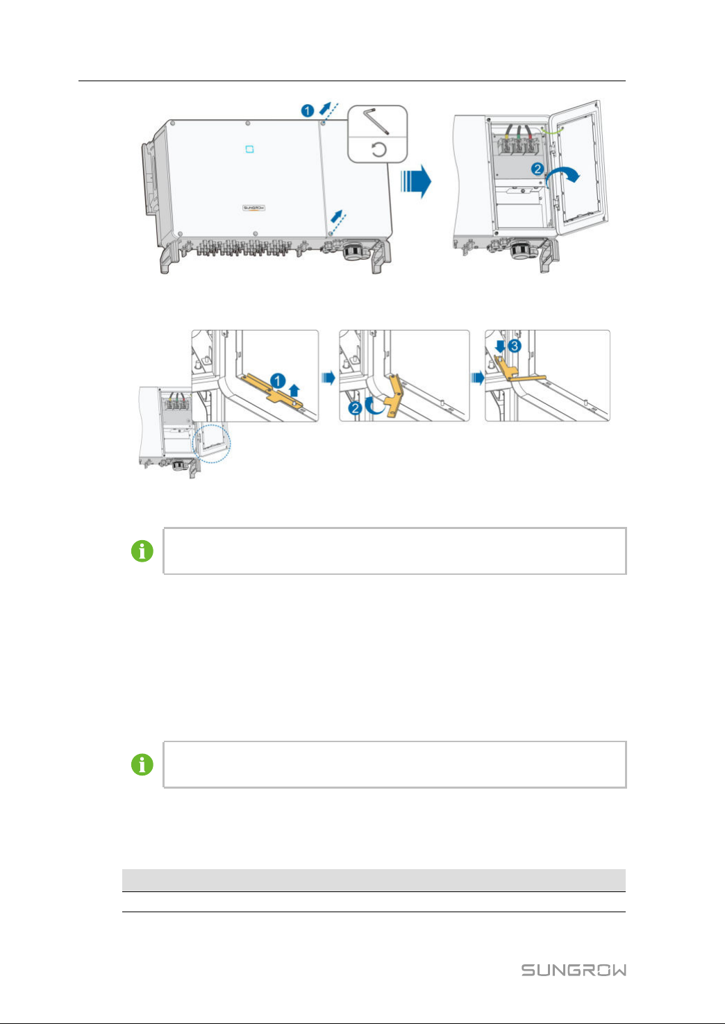
step1ReleasetwoscrewsonthefrontcoverofthewiringcompartmentwithsuppliedAllen
wrench.
step2Openthewiringcompartment.
31
Page 42
5ElectricalConnectionUserManual
step3Keepthewiringcompartmentopenedduringwiringthroughthelimitleverattachedto
thecover.
----EEnndd
Closethewiringcompartmentinreverseorderaftercompletingwiring
operations.
5.6ACCableConnection
5.6.1 ACSideRequirements
Before connectingthe invertertothegrid, ensurethegridvoltageand frequency
complywithrequirements,forwhich,referto
theelectricpowercompanyforhelp.
Connecttheinvertertothegridonlyaftergettinganapprovalfromthelocal
electricpowercompany.
AACCCCiirrccuuiittBBrreeaakkeerr
Anindependentthree-polecircuitbreakerisinstalledontheoutputsideoftheinverter
toensuresafedisconnectionfromthegrid.
RReeccoommmmeennddeeddrraatteeddvvoollttaaggee
800V250A
"10.1TechnicalData".Otherwise,contact
RReeccoommmmeennddeeddrraatteeddccuurrrreenntt
32
Page 43
UserManual5ElectricalConnection
If multipleinverters needtoshareacircuit breaker,thecircuitbreakershould be
selectedaccordingtothecapacity.
Neverconnectaloadbetweentheinverterandthecircuitbreaker.
MMuullttiipplleeIInnvveerrtteerrssiinnppaarraalllleellCCoonnnneeccttiioonn
Ifmultipleinvertersareconnectedinparalleltothegrid,ensurethatthetotalnumberof
parallel inverters does not exceed 28.Otherwise, please contact SUNGROW for
technicalscheme.
MMVVttrraannssffoorrmmeerr
The MVtransformerusedtogether withtheinverter shouldmeetthe following
requirements:
• Thetransformermaybeadistributiontransformer,anditmustbedesignedforthe
typicalcyclicalloadsofaPVsystem(loadinthedayandnoloadatnight).
• Thetransformermaybeoftheliquid-immersedtypeordrytype,andshieldwinding
isnotnecessary.
• Theline-to-linevoltageontheLVsideofthetransformershouldenduretheoutput
voltageofinverter.WhenthetransformerisconnectedtototheITgrid,to-ground
withstandingvoltageoftheLVwindingofthetransformer,theACcables,andthe
secondaryequipment(includingtherelayprotectiondevice,detection&measuring
device,andotherrelatedauxiliarydevices)shouldnotbelowerthan1,100V.
• Theline-to-linevoltageontheHVside oftransformershouldcomplywithlocal
powergridvoltage.
• AtransformerwithatapchangerontheHVsideisrecommendedinordertokeep
consistentwiththegridvoltage.
• Atanambienttemperatureof45℃,thetransformercanrunin1.1timesofloadfor
longtime.
• Transformerwithashort-circuitimpedance6%(permissibletolerance:±10%)is
recommended.
• Thevoltagedropofsystemcableisnomorethan3%.
• TheDCcomponentthatthetransformercanwithstandis1%ofthefundamental
currentatratedpower.
• Forthermalrating,theloadcurveofthetransformerandenvironmentconditions
shouldbetakenintoaccount.
• Theapparent powerofthe invertershouldnever exceedthepower ofthe
transformer.ThemaximumACcurrentofallinvertersconnectedinparallelmustbe
takenintoaccount.Ifmorethan28invertersareconnectedtothegrid,contact
SUNGROW.
• Thetransformermustbeprotectedagainstoverloadingandshortcircuit.
33
Page 44
5ElectricalConnectionUserManual
• Thetransformerisanimportantpartofgrid-connectedPVgenerationsystem.The
faulttolerancecapacityofthetransformershouldbetakenintoaccountatalltimes.
Thefaultinclude:systemshortcircuit,groundingfault,voltagedrop,etc.
• Takeambienttemperature,relativehumidity,altitude,airquality,andother
environmentalconditionsintoaccountwhenselectingandinstallingthetransformer.
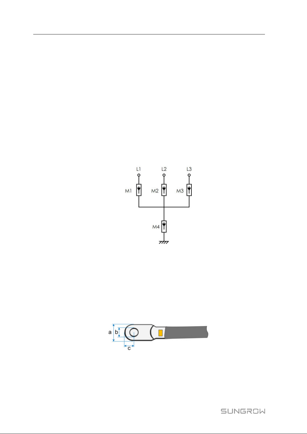
• Whentheanti-PIDfunctionisenabled,observethefollowingitems:
–IftheLVsidewindingisinYshape,neutralpointgroundingisprohibited.
–Surgeprotectivedevices(SPD)fortheACcombinerboxandontheLVsideof
thetransformerarerecommendedtobeconnectedinthe"3+1"manner,as
showninthefigurebelow.TheMin.continuousoperatingvoltagesofM1-M4are
750VAC.
–TheLVsidewindingofthetransformer,ACcables,andsecondarydevices(-
includingprotectiverelay,detectionandmeasurementinstruments,andrelated
auxiliarydevices)mustwithstandthevoltagetogroundofatleast906V.
5.6.2 RequirementsforOT/DTTerminal
OT/DTterminals(notincludedinthedeliveryscope)arerequiredforfixingACcablesto
theterminalblock.PurchasetheOT/DTterminalsaccordingtothefollowing
requirements.
OOTT//DDTTTTeerrmmiinnaallssooffPPhhaasseeWWiirree
• Specification:M12;
• Dimensions:a≤46mm/13mm≤b≤15.5mm/c≤22mm
ffiigguurree55--22DimensionsofTerminal
OOTT//DDTTTTeerrmmiinnaallooffPPEEWWiirree
• Specification:M8/M10.
34
Page 45
UserManual5ElectricalConnection
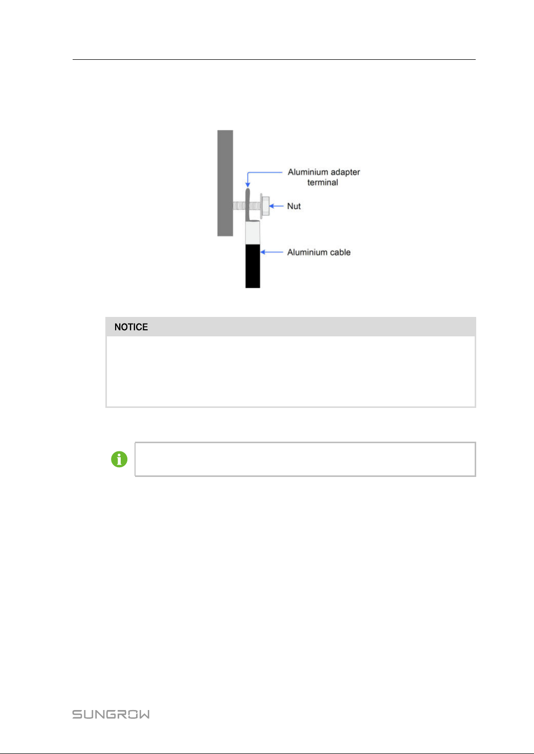
5.6.3 AluminiumCableRequirements
Ifanaluminiumcableisselected,useacoppertoaluminiumadapterterminaltoavoid
directcontactbetweenthecopperbarandthealuminiumcable.
ffiigguurree55--33Aluminiumcableterminalconnectionsequence
Ensurethattheselectedterminalcandirectlycontactwiththecopperbar.If
thereareanyproblems,contactthemanufacturerofterminal.
Directcontactbetweenthecopperbarandthealuminiumcablewillcause
electrochemicalcorrosionandimpairthereliabilityofelectricalconnection.
5.6.4 ConnectionProcedure
Inthismanual,descriptionisgivenbyusingfive-corecableasanexample.
Thewiringmethodofthefour-corecableisthesame.
step1Openthewiringcompartment.Fordetails,referto
Compartment"
.
step2DisconnecttheAC-sidecircuitbreakerandpreventitfrominadvertentreconnection.
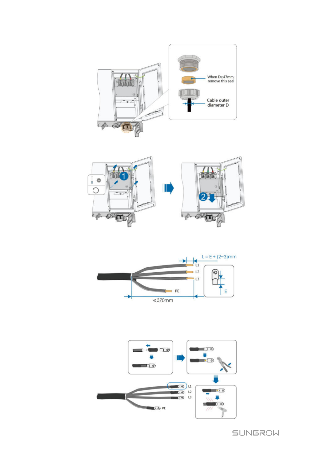
step3LoosentheswivelnutoftheACwaterproofconnectorandselectasealaccordingto
thecableouterdiameter. Leadthecablethrough theswivelnut, seal,andwiring
terminalsuccessively.
"5.5OpeningtheWiring
35
Page 46
5ElectricalConnectionUserManual
step4Removetheprotectioncoverandstorethereleasedscrewsproperly.
step5Striptheprotectionlayerandinsulationlayerbyspecificlength,asdescribedinthe
figurebelow.
step6Ifwiringoftrackingsystempowercableisrequired,referto"5.8WiringofTracking
SystemPowerCable(Optional)"
.Otherwise,skipperformingthisstep.
step7MakethecableandcrimpOT/DTterminal.
36
Page 47
UserManual5ElectricalConnection
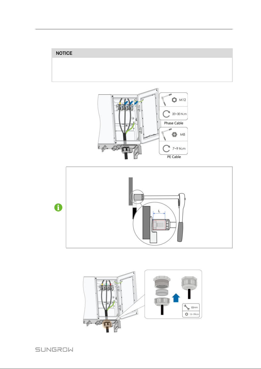
step8Securethewirestocorrespondingterminals.
NotetheterminalpositionsofPEwireandNwire.Ifaphasewireisconnected
tothePEterminalorNterminal,unrecoverabledamagemaybecausedtothe
inverter.
EnsurethatthedepthLofthesocketusedisnotlessthan28mm.
step9Gentlypullthecablebackwardstoensurefirmconnection,andfastentheswivelnut
clockwise.
37
Page 48
5ElectricalConnectionUserManual
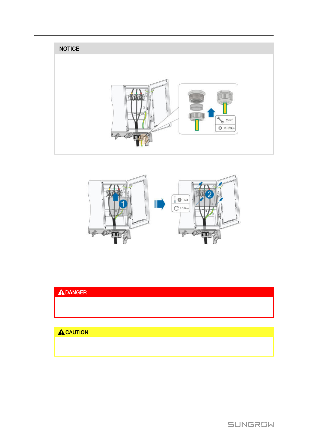
IfthePEcableisanindependentsingle-corecable,itisinsertedintothecabinet
throughthestandbygroundingterminal.
step10Installtheprotectioncover
----EEnndd
5.7DCCableConnection
Electricshock!
ThePVarraywillgeneratelethalhighvoltageonceexposedtosunlight.
MakesurethePVarrayiswellinsulatedtogroundbeforeconnectingittothe
inverter.
38
Page 49
UserManual5ElectricalConnection
Thereisariskofinverterdamage!Thefollowingrequirementsshouldbemet.
Failuretodosowillvoidguaranteeandwarrantyclaims.
• Makesurethemaximumvoltageofeachstringisalwayslessthan1500V.
• MakesurethemaximumshortcircuitcurrentontheDCsideiswithinthe
permissiblerange.
5.7.1 PVInputConfiguration
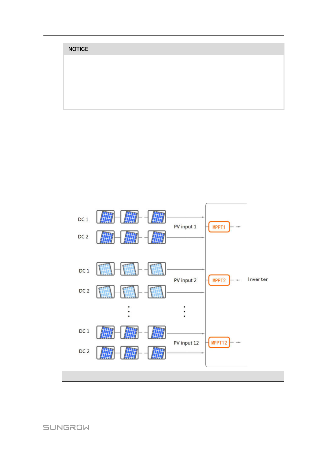
Asshowninthefigurebelow,theinverterisprovidedwithmultiplePVinputs:PVinputs
1~12;andeachPVinputisdesignedwithanMPPtracker.
Each PVinput operates independentlyand has itsown MPPT.Inthisway,string
structuresofeachPVinputmaydifferfromeachother,including PVmoduletype,
numberofPVmodulesineachstring,angleoftilt,andinstallationorientation.
EachPVinputareaincludestwoDCinputsDC1andDC2.ForthebestuseofDCpower,
DC1andDC2shouldbethesameinPVstringstructure,includingthetype,number,tilt,
andorientationofthePVmodules.
OOppeenncciirrccuuiittvvoollttaaggeelliimmiittMMaaxx..ccuurrrreennttffoorriinnppuuttccoonnnneeccttoorr
1,500V
30A
39
Page 50
5ElectricalConnectionUserManual
5.7.2 ConnectionProcedure
SUNGROWprovidescorrespondingplugconnectorsinthescopeofdeliveryforquick
connectionofPVinputs.
DCcablesshouldbeconnectedtotheinverterviaPVconnectorswhichareincludedin
thescopeofdelivery.
ToensureIP66protection,useonlythesuppliedconnectorortheconnector
withthesameingressofprotection.
Highvoltagemaybepresentintheinverter!
• Ensureallcablesarevoltage-freebeforeperformingelectricaloperations.
• DonotconnecttheACcircuitbreakerbeforefinishingelectricalconnection.
UsetheMC4EVO2PVconnecterswithinthescopeofdelivery.Damagetothe
deviceduetotheuseofincompatibleterminalshallnotbecoveredbythe
warranty.
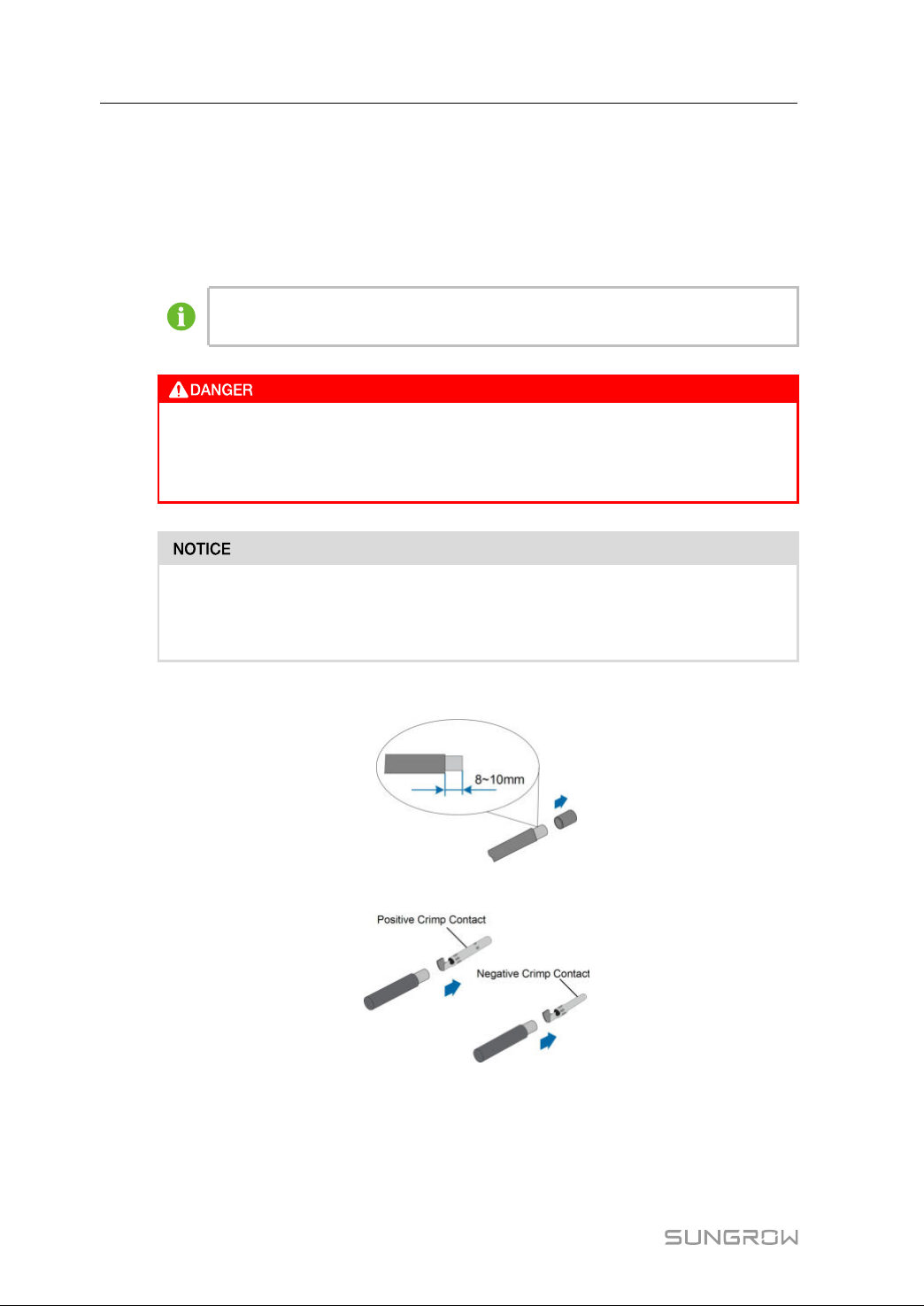
step1StriptheinsulationfromeachDCcable.
step2Assemblethecableendswiththecrimpingpliers.
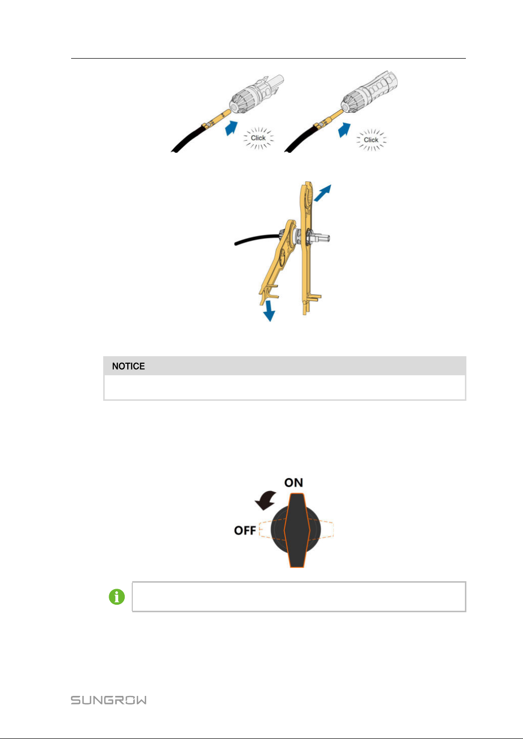
step3Insertthecrimpedcablesintothecorrespondingconnectorsuntiltheysnapintoplace.
Gentlypullthecablebackwardtoensurefirmconnection.
40
Page 51
UserManual5ElectricalConnection
step4Tightenthecableglandandtheinsulator.
step5Checkforpolaritycorrectness.
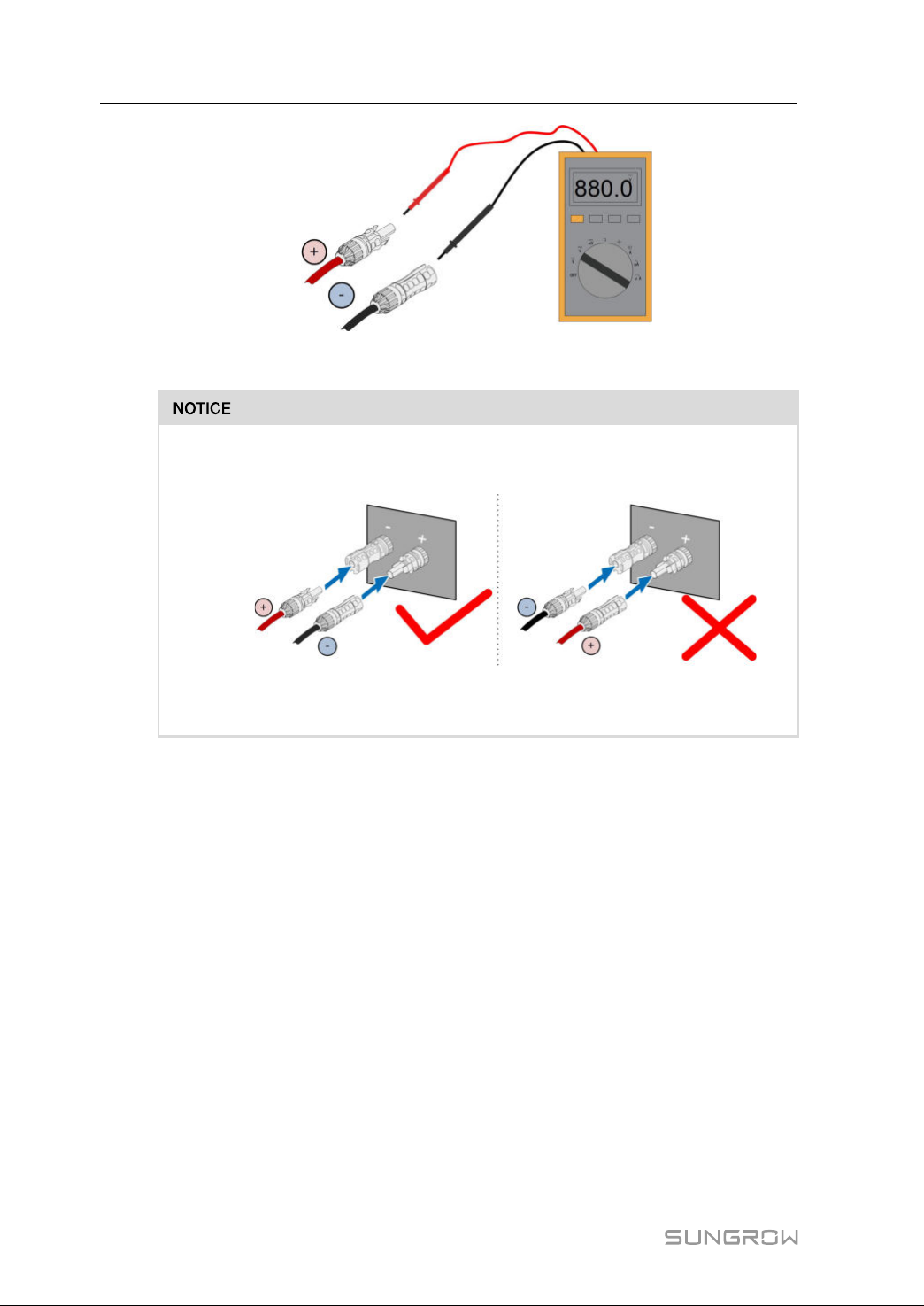
TheinverterwillnotfunctionproperlyifanyPVpolarityisreversed.
----EEnndd
5.7.3 InstallingthePVConnectors
step1RotatealltheDCswitchesto"OFF"position.
Skipperformingstep1whentheactualdeviceisnotequippedwithDC
switches.
step2CheckthecableconnectionofthePVstringforpolaritycorrectnessandensurethatthe
opencircuitvoltageinanycasedoesnotexceedtheinverterinputlimitof1,500V.
41
Page 52
5ElectricalConnectionUserManual
step3ConnectthePVconnectorstocorrespondingterminalsuntilthereisanaudibleclick.
CheckthepositiveandnegativepolarityofthePVstrings,andconnectthePV
connectorstocorrespondingterminalsonlyafterensuringpolaritycorrectness.
ArcorcontactorovertemperaturemayoccurifthePVconnectorsarenotfirmly
inplace,andSUNGROWshallnotbeheldliableforanydamagecaused.
step4FollowtheforegoingstepstoconnectPVconnectorsofotherPVstrings.
step5SealtheunusedPVterminalswiththeterminalcaps.
----EEnndd
5.8WiringofTrackingSystemPowerCable(Optional)
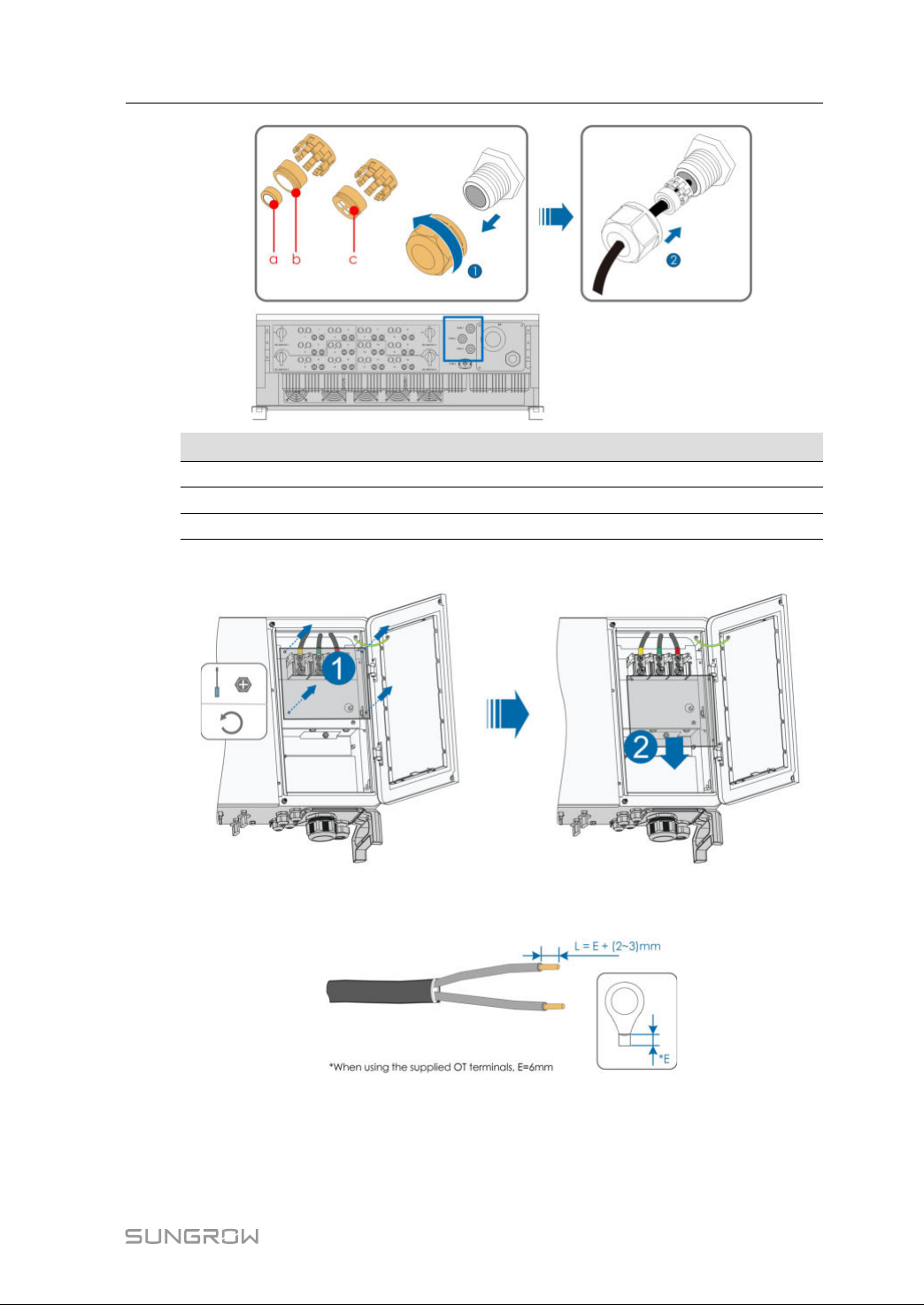
step1LeadtheACcableintothewiringcompartmentaccordingtoStep1toStep4described
in"5.6.4ConnectionProcedure".
step2Loosentheswivelnutofthecommunicationterminalandselectanappropriateseal
accordingtocableouterdiameter.Leadthecablethroughthe swivelnutandseal
successively.
42
Page 53
UserManual5ElectricalConnection
OOuutteerrddiiaammeetteerrDD((mmmm))
4.5~6
SSeeaall
c
6~12a+b
13~18b
step3Removetheprotectioncoverandstorethereleasedscrewsproperly.
step4Striptheprotectionlayerandinsulationlayerbyspecificlength,asdescribedinthe
figurebelow.
step5InstalltheOTterminalandpressittight.
43
Page 54
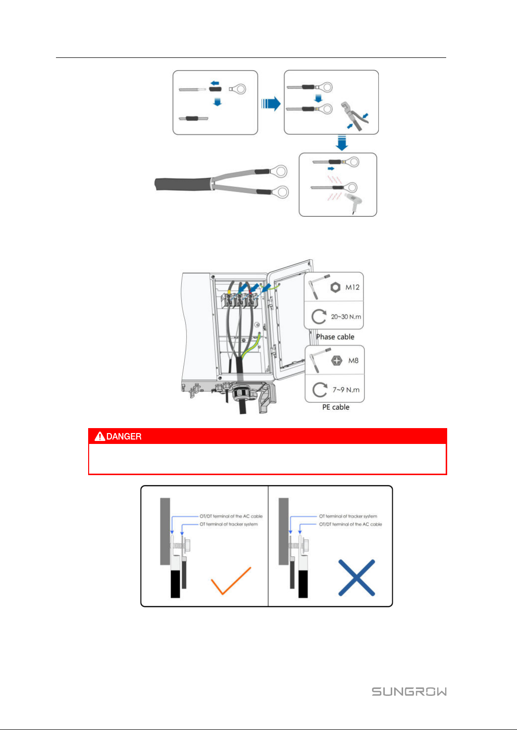
5ElectricalConnectionUserManual
step6StacktheOTterminalsontheOT/DTterminaloftheACcables,andfixthecablesto
correspondingterminals.
EnsurethatOTterminalsofthepowercableareinstalledontheOT/DT
terminalsoftheACcable.Otherwise,itwillcauseoverheatorevenburn.
step7Gentlypullthecablebackwardstoensurefirmconnection,andfastentheswivelnut
clockwise.
44
Page 55
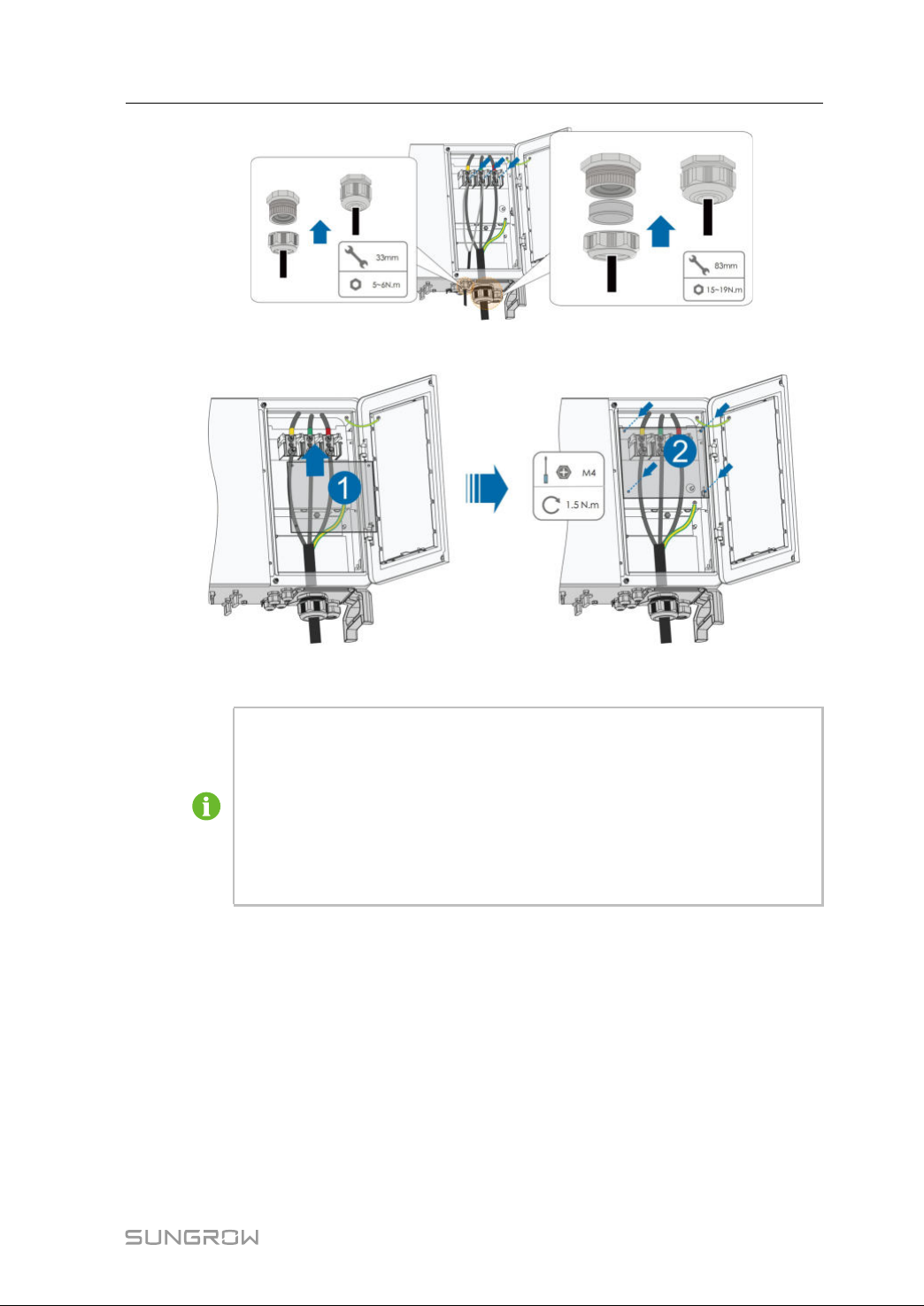
UserManual5ElectricalConnection
step8Installtheprotectioncover
----EEnndd
TherearefourcommunicationterminalsCOM1,COM2,COM3andCOM4on
thebottomoftheinverter.Selectthecommunicationterminalaccordingto
onsiteconditions.
Disconnector(≥540V)andfuse(16A,gM)shouldbeinstalledbetweenthe
inverterandthetrackingsystemcontrolcabinet.
Lengthofthecableconnectingtheinternalwiringterminaloftheinverterand
thefuseshouldbelessthan2.5m.
5.9RS485Communication
5.9.1 InterfaceDescription
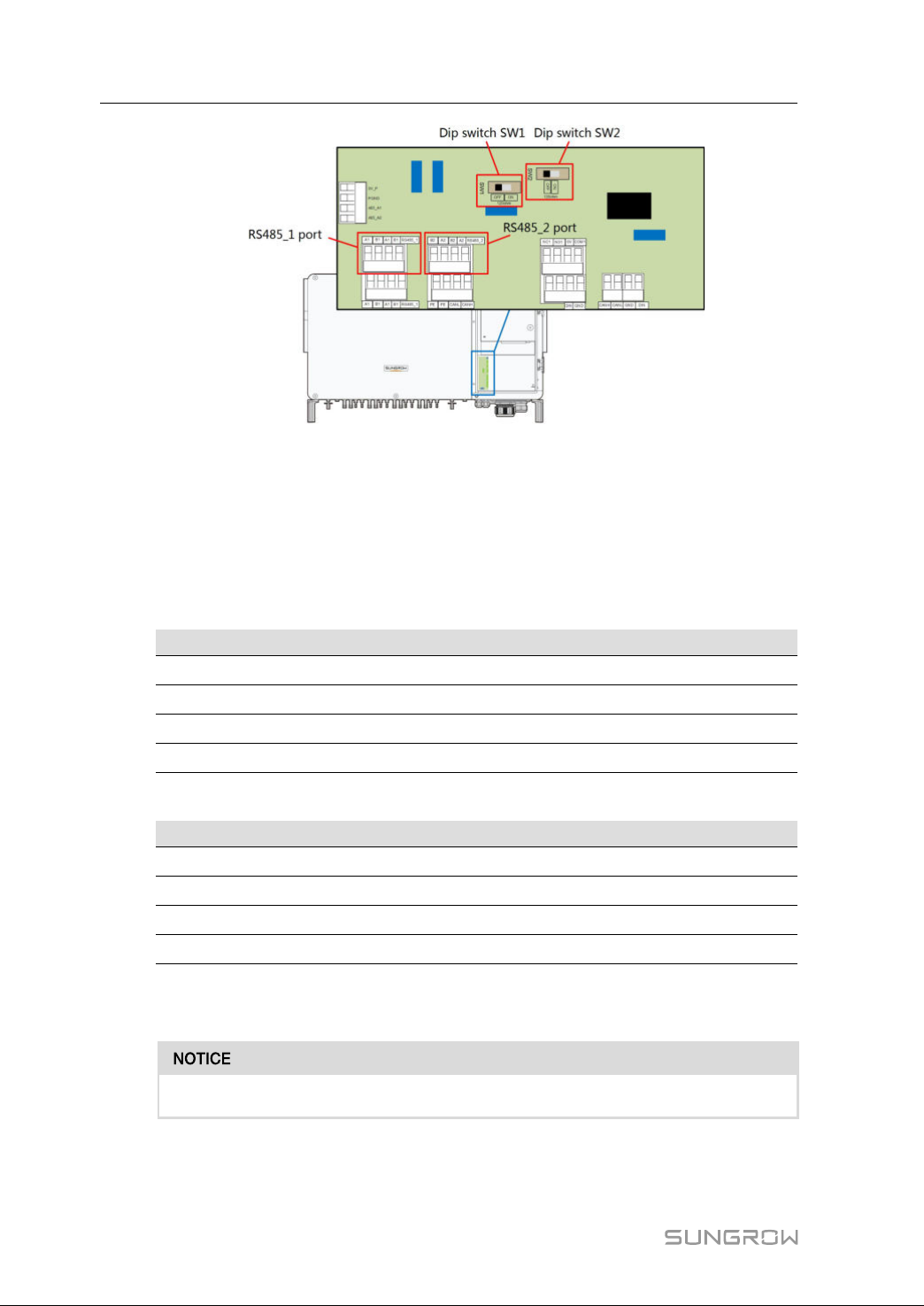
Thefollowingfigureshows thepositionof thecommunicationwiringboard inthe
inverteraswellastheterminalsequippedforthewiringboard.
45
Page 56
5ElectricalConnectionUserManual
The inverterisequipped with twogroupsof RS485 communicationinterfacesfor
externalcommunicationconnection.
TheportRS485_1isusedtoconnectLogger,soastoimplementdataexchangewith
PCorothermonitoringdevices.TheportRS485_2isusedtoconnectcommunication
deviceofthetrackingsystem,soastoimplementdataexchangewiththetracking
system.Terminaldefinitionsofthetwoportsareasfollows:
table5-4RS485_1portterminaldefinition
NNoo..DDeeffiinniittiioonn
A1
B1
A1
B1
table5-5RS485_2portterminaldefinition
RS485AIN,RS485Adifferentialsignal+
RS485BIN,RS485Bdifferentialsignal-
RS485AOUT,RS485Adifferentialsignal+
RS485BOUT,RS485Bdifferentialsignal-
NNoo..DDeeffiinniittiioonn
B2
A2
B2
A2
RS485BOUT,RS485Bdifferentialsignal-
RS485AOUT,RS485Adifferentialsignal+
RS485BIN,RS485Bdifferentialsignal-
RS485AIN,RS485Adifferentialsignal+
TheterminalblockinterfaceandRJ45interfacehavethesamefunctionwithonlywiring
mannerdifferent.Selecteitherinterfaceforcableconnection.
TheRS485_1interfaceismarkedasSW2.
46
Page 57
UserManual5ElectricalConnection
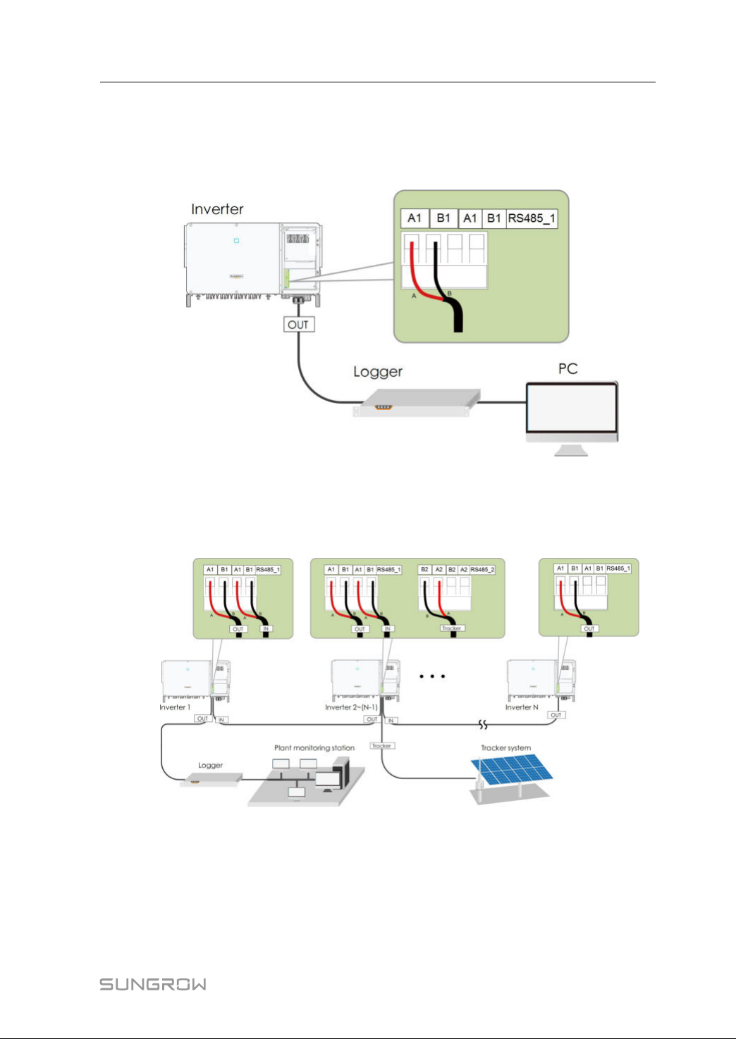
5.9.2 RS485CommunicationSystem
SSiinnggllee--iinnvveerrtteerrccoommmmuunniiccaattiioonnssyysstteemm
Incaseofasingleinverter,communicationcableconnectionrequiresonlyoneRS485
cable.
MMuullttii--iinnvveerrtteerrccoommmmuunniiccaattiioonnssyysstteemm
Incaseofmultipleinverters,alltheinverterscanbeconnectedviaRS485cablesinthe
daisychainmanner. Thecommunicationcableofthetrackingsystem canbe
connectedtotheportRS485_2ofanyinverterinthedaisychain.
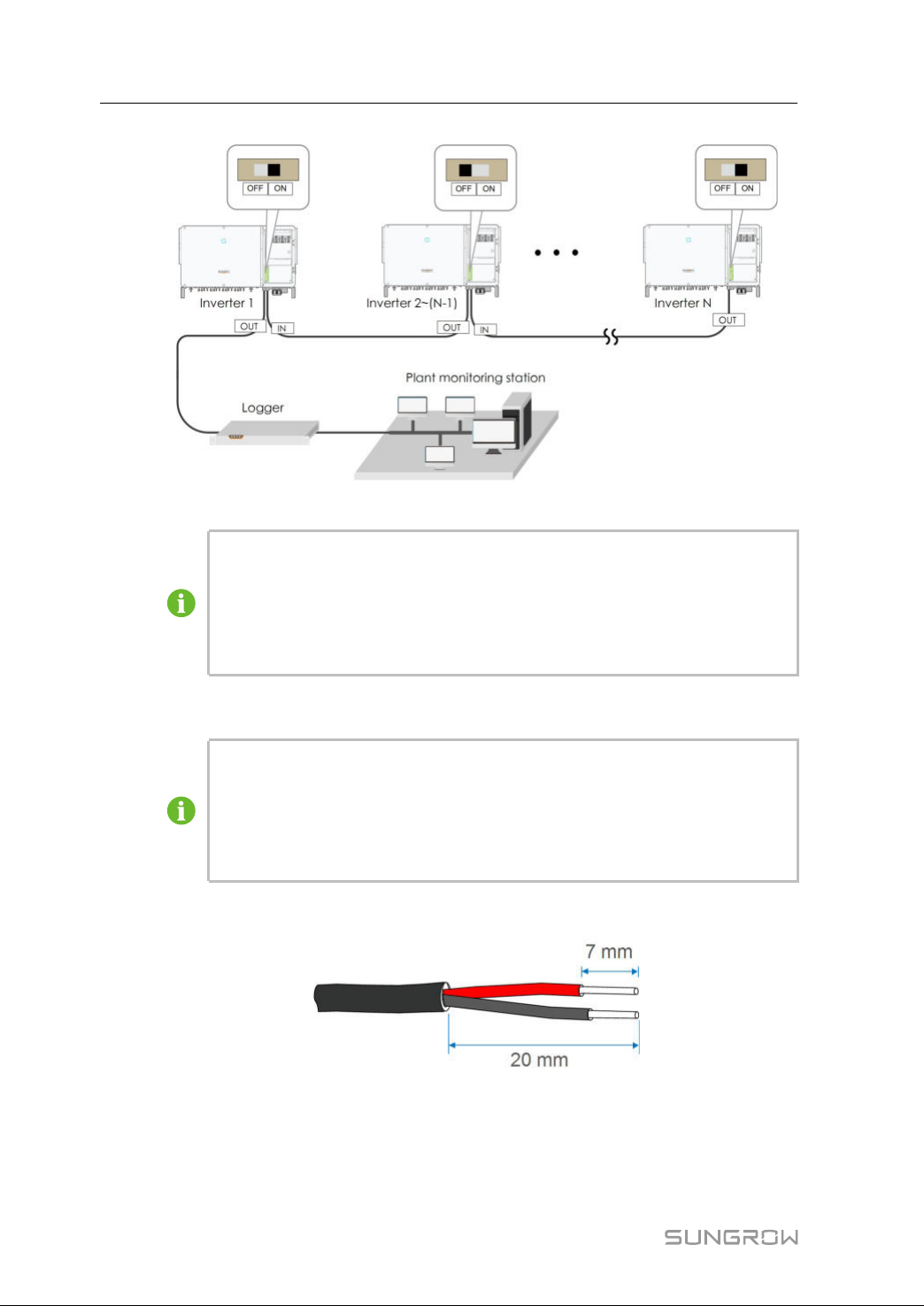
Whenmorethan15invertersareconnectedonthesamedaisychain,configurethe
RS485-dipswitchesoftheinvertersontwoendsofthechain(RS485_1is
correspondingtoSW2,andRS485_2iscorrespondingtoSW1),toensure
communicationquality.
47
Page 58
5ElectricalConnectionUserManual
ffiigguurree55--44Configurationofdipswitch(N≥15)
ThelengthoftheRS485cableshouldbenolongerthan1,200m.
IfmultipleinvertersareconnectedtothedatacollectorLogger3000,the
numberofpermissibledaisychainsandthenumberofdevicesallowedtobe
connectedshouldmeettherequirements(refertotheusermanualforthe
Logger3000).
5.9.3 ConnectionProcedure(TerminalBlock)
RS485communicationcablesshouldbeshieldedtwistedpaircablesor
shieldedtwistedpairEthernetcables.
TherearefourRS485communicationterminalsCOM1,COM2,COM3and
COM4onthebottomoftheinverter.Pleasechooseaccordingtotheactual
situation.
step1Striptheprotectionlayerandinsulationlayerbyappropriatelength.
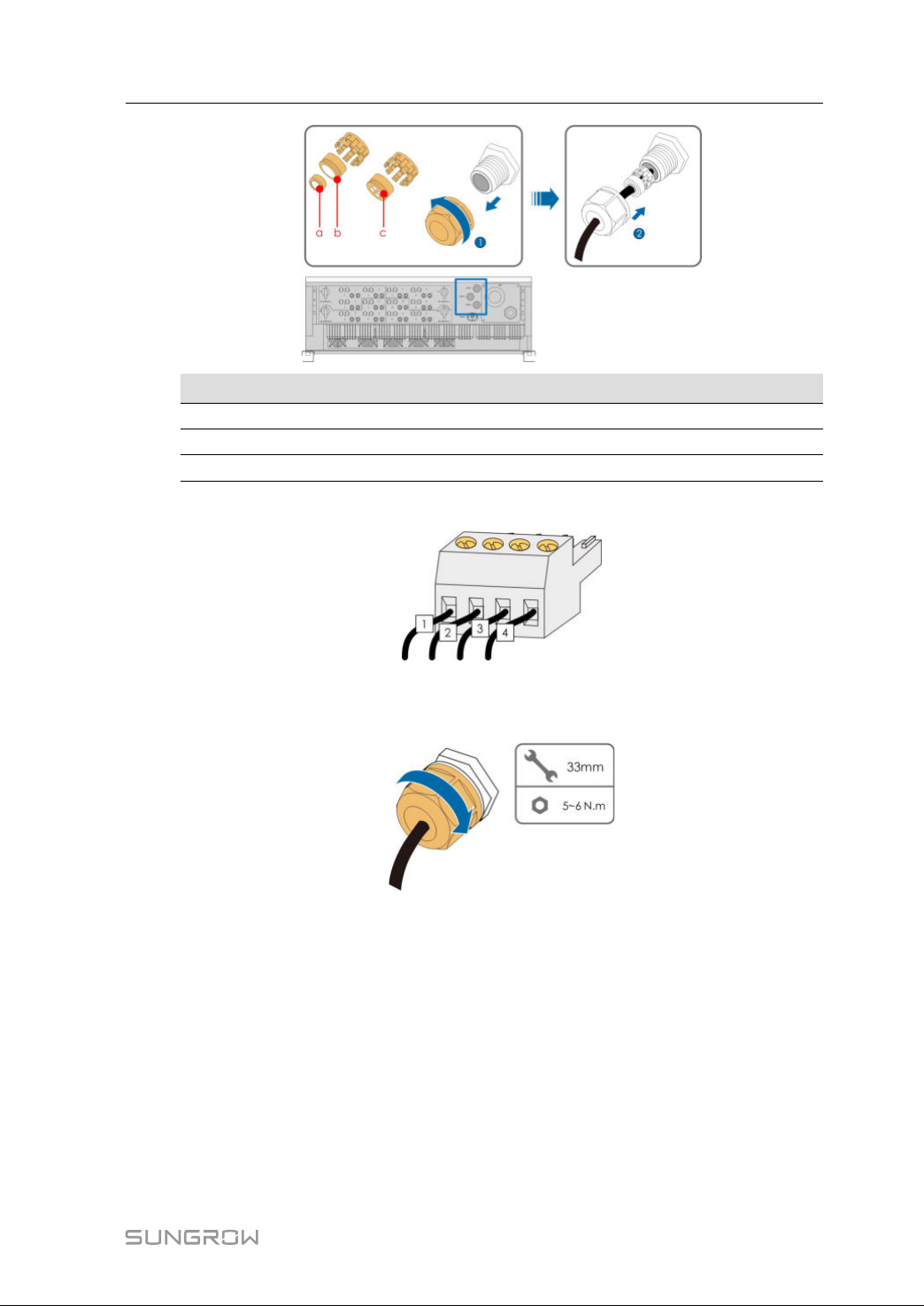
step2Loosentheswivelnutofthecommunicationterminalandselectanappropriateseal
accordingtocableouterdiameter.Leadthecablethroughthe swivelnutandseal
successively.
48
Page 59
UserManual5ElectricalConnection
OOuutteerrddiiaammeetteerrDD((mmmm))
4.5~6
6~12a+b
12~18b
step3Securethecabletotheterminalbase.
step4Inserttheterminalbaseintothecorrespondingterminal.
step5Pullthecablegentlytomakesureitissecured,tightentheswivelnutclockwise.
SSeeaall
c
----EEnndd
5.10PLCCommunicationConnection
WithaPLCcommunicationmodulebuiltinside,theinvertercancommunicatewiththe
PLCBOXprovidedbySUNGROW.Forspecificwiringmethod,refertothePLCBOX
usermanual.
49
Page 60
5ElectricalConnectionUserManual
• IncaseofPLCcommunication,theACcablemustbeamulti-corecable
ratherthanmultiplesingle-corecables.
• ThePLCBoxisanoptionaldevicethatcanbeorderedfromSungrow.
• ThePLCBoxconductsdatacommunicationbydirectlyusingtheACoutput
cableoftheinverterandthussavesthetroubletolayandmaintainthe
specialcommunicationcables.TheRS-485portofthePLCBoxsupports
the transparent transmission of the MODBUS-RTU and iscompletely
compatiblewiththemonitoringdevicesandsoftwareoftheoriginalRS-
485communicationmethod.
5.11DryContactConnection
Drycontactcablesrequireacrosssectionof1mm2to1.5mm2.
TheconnectionprocedureofthedrycontactisthesameasthatoftheRS485
terminalblock.
5.11.1DryContactFunction
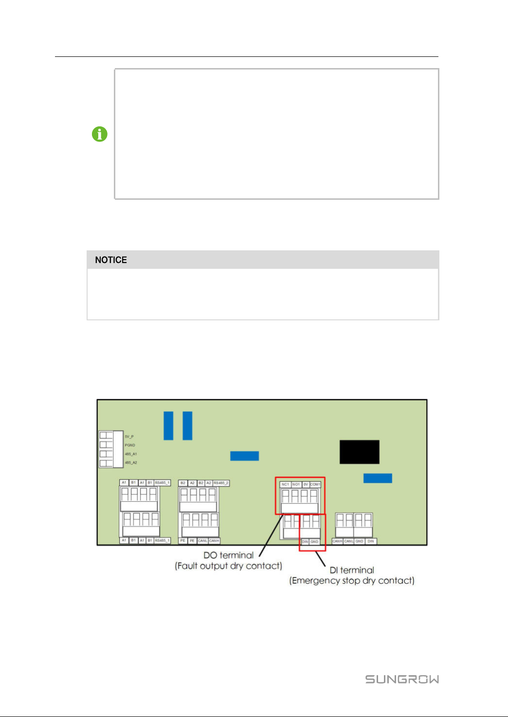
Theconfigurationcircuitboardisprovidedwithfaultoutputdrycontactandemergency
stopdrycontact,asshowninthefigurebelow.
ConnectionmethodofthedrycontactsissimilartothatoftheRS485terminalblock.
DDOOtteerrmmiinnaall((ffaauullttoouuttppuuttddrryyccoonnttaacctt))::therelaycanbesettofaultalarmoutput,and
usercanconfigureittobeanormalopencontact(COM&NO)oranormalclosecontact
(COM&NC).
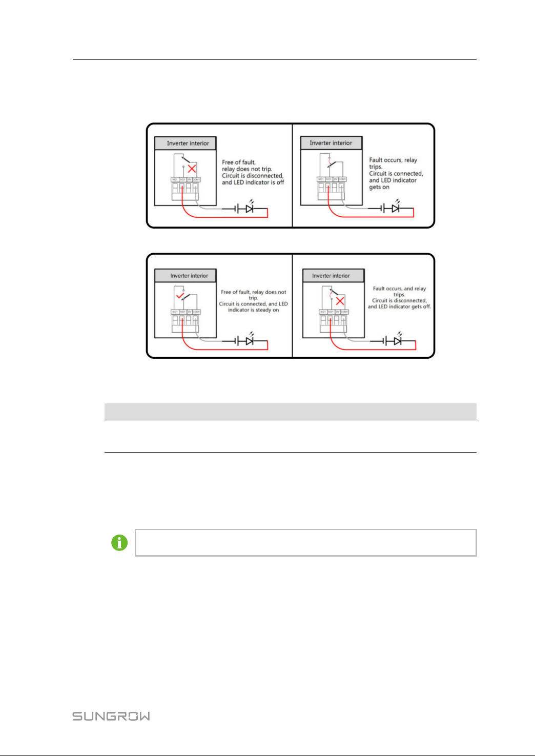
TherelayisinitiallyattheNCterminal,anditwilltriptoanothercontactwhenafault
occurs.
50
Page 61
UserManual5ElectricalConnection
UseLEDindicatorsorotherequipmenttoindicatewhethertheinverterisinthefaulty
state.Thefollowingfiguresshowthetypicalapplicationsofnormalopencontactand
normalclosecontact:
ffiigguurree55--55Normalopencontact
ffiigguurree55--66Normalclosecontact
Devicesconnectedtotherelayshouldcomplywithrelatedrequirements:
AACC--SSiiddeeRReeqquuiirreemmeennttssDDCC--SSiiddeeRReeqquuiirreemmeennttss
Max.voltage:250Vac
Max.current:5A
Max.voltage:30Vdc
Max.current:5A
DDIItteerrmmiinnaall((eemmeerrggeennccyyssttooppddrryyccoonnttaacctt))::thedrycontactcanbeconfiguredtobean
emergencystopcontact.
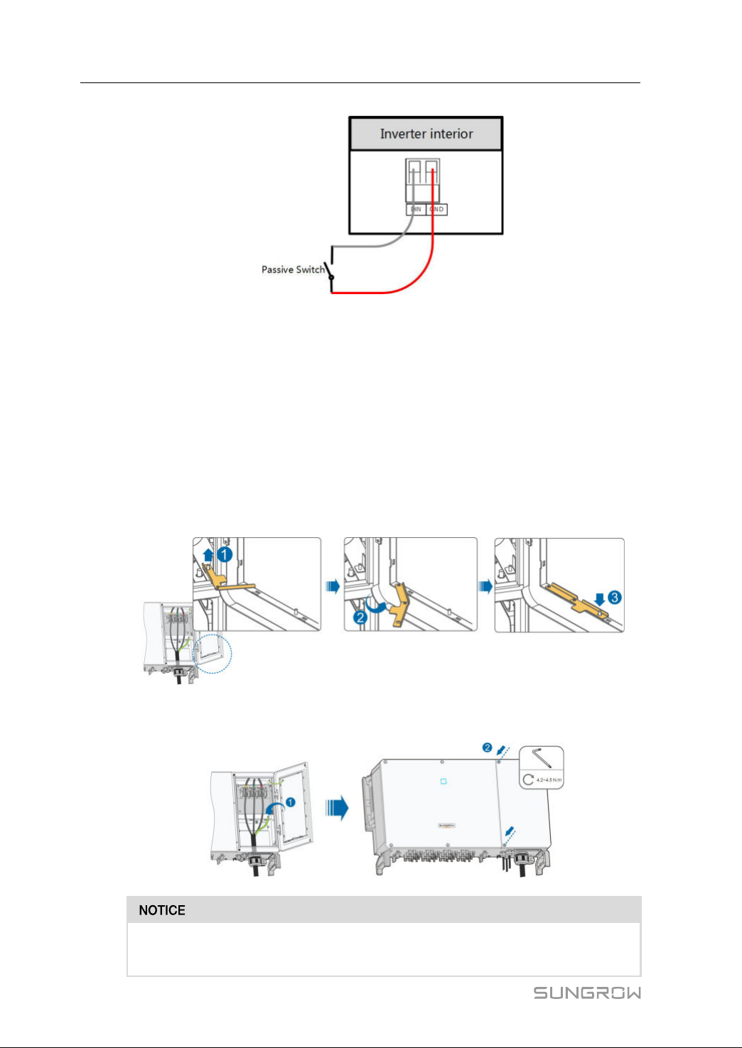
WhentheDIcontactandGNDcontactareshortedbyexternalcontrolledswitch,the
inverterwillimmediatelystop.
Thedrycontactsonlysupportpassiveswitchsignalinput.
Thefollowingfigureshowsthetypicalapplicationoflocalstopdrycontact.
51
Page 62
5ElectricalConnectionUserManual
ffiigguurree55--77Localstopcontact
When wiringDI dry contacts,ensurethat the maximumwiring distance meetthe
requirementsin
"10.2WringDistanceofDIDryContact".
5.11.2WiringProcedure
Refertothewiringofterminalblockdescribedinchapter"5.9.3ConnectionProcedure(-
TerminalBlock)"
.
5.12ClosingtheWiringCompartment
step1Releasethelimitlever.
step2Close thewiringcompartmentand tightenthetwo screwsonitsfront coverwith
suppliedAllenwrench.
52
Incasethescrewsonthecoveraremissing,youcanfindspareonesinthe
scopeofdelivery.
Page 63

UserManual5ElectricalConnection
----EEnndd
53
Page 64

6
Commissioning
6.1InspectionbeforeCommissioning
Checkthefollowingitemsbeforestartingtheinverter:
• TheinverterDCswitchandexternalcircuitbreakeraredisconnected.
• Theinvertershouldbeaccessibleforoperation,maintenanceandservice.
• Nothingisleftonthetopoftheinverter.
• Theinverteriscorrectlyconnectedtotheexternaldevices,andthecablesarerouted
inasafeplaceorprotectedagainstmechanicaldamage.
• TheselectionoftheACcircuitbreakerisinaccordancewiththismanualandall
applicablelocalstandards.
• Allunusedterminalsatthebottomoftheinverterareproperlysealed.
• Warningsigns&labelsaresuitablyaffixedanddurable.
6.2CommissioningProcedure
Ifalloftheitemsmentionedabovemeettherequirements,proceedasfollowstostart
uptheinverterforthefirsttime.
step1RotatetheDCswitchoftheinverterto"ON"position.
step2ConnecttheACswitch(ifapplicable)betweentheinverterandthegrid.
step3ConnecttheDCswitch(ifapplicable)betweentheinverterandthePVstring.
step4Set initial protectionparametersviatheiSolarCloudApp.Fordetails,please refer
to“7.4.2LoginSteps”.Iftheirradiationandgridconditionsmeetrequirements,the
inverterwillnormallyoperate.
step5ObservetheLEDindicatortoensurethattheinverteroperatesnormally.(RefertoTab.
2-2LEDindicatordescription).
----EEnndd
54
Page 65
7
iSolarCloudApp
7.1BriefIntroduction
TheiSolarCloudAppcanestablishcommunicationconnectiontotheinverterviathe
Bluetooth,therebyachievingnear-endmaintenanceontheinverter.Userscanusethe
Apptoviewbasicinformation,alarms,andevents,setparameters,ordownloadlogs,
etc.
*IncasethecommunicationmoduleEyeorWiFiisavailable,theiSolarCloudAppcan
alsoestablishcommunicationconnectiontotheinverterviathemobiledataorWiFi,
therebyachievingremotemaintenanceontheinverter.
Thismanualdescribesonlyhowtoachievenear-endmaintenanceviathe
Bluetoothconnection.ForremotemaintenancethroughtheEyeorWiFi,refer
totherelatedmanualsinthedeliveryscope.
ScreenshotsinthismanualarebasedontheAndroidsystemV2.1.6,andthe
actualinterfacesmaydiffer.
7.2DownloadandInstall
MMeetthhoodd11
DownloadandinstalltheAppthroughthefollowingapplicationstores:
• MyApp(Android,mainlandChinausers)
• GooglePlay(Android,usersotherthanmainlandChinaones)
• Appstore(iOS)
MMeetthhoodd22
ScanthefollowingQRcodetodownloadandinstalltheAppaccordingtotheprompt
information.
TheAppiconappearsonthehomescreenafterinstallation.
55
Page 66
7iSolarCloudAppUserManual
7.3FunctionOverview
TheAppprovidesparameterviewingandsettingfunctions,asshowninthefollowing"-
figure7-1Appfunctiontreemap"
.
ffiigguurree77--11Appfunctiontreemap
7.4Login
7.4.1 Requirements
Thefollowingitemsshouldmeetrequirements:
• TheACandDCsidesortheACsideoftheinverterispowered-on.
• Themobilephoneiswithin5mawayfromtheinverterandtherearenoobstructions
inbetween.
• TheBluetoothfunctionofthemobilephoneisenabled.
7.4.2 LoginSteps
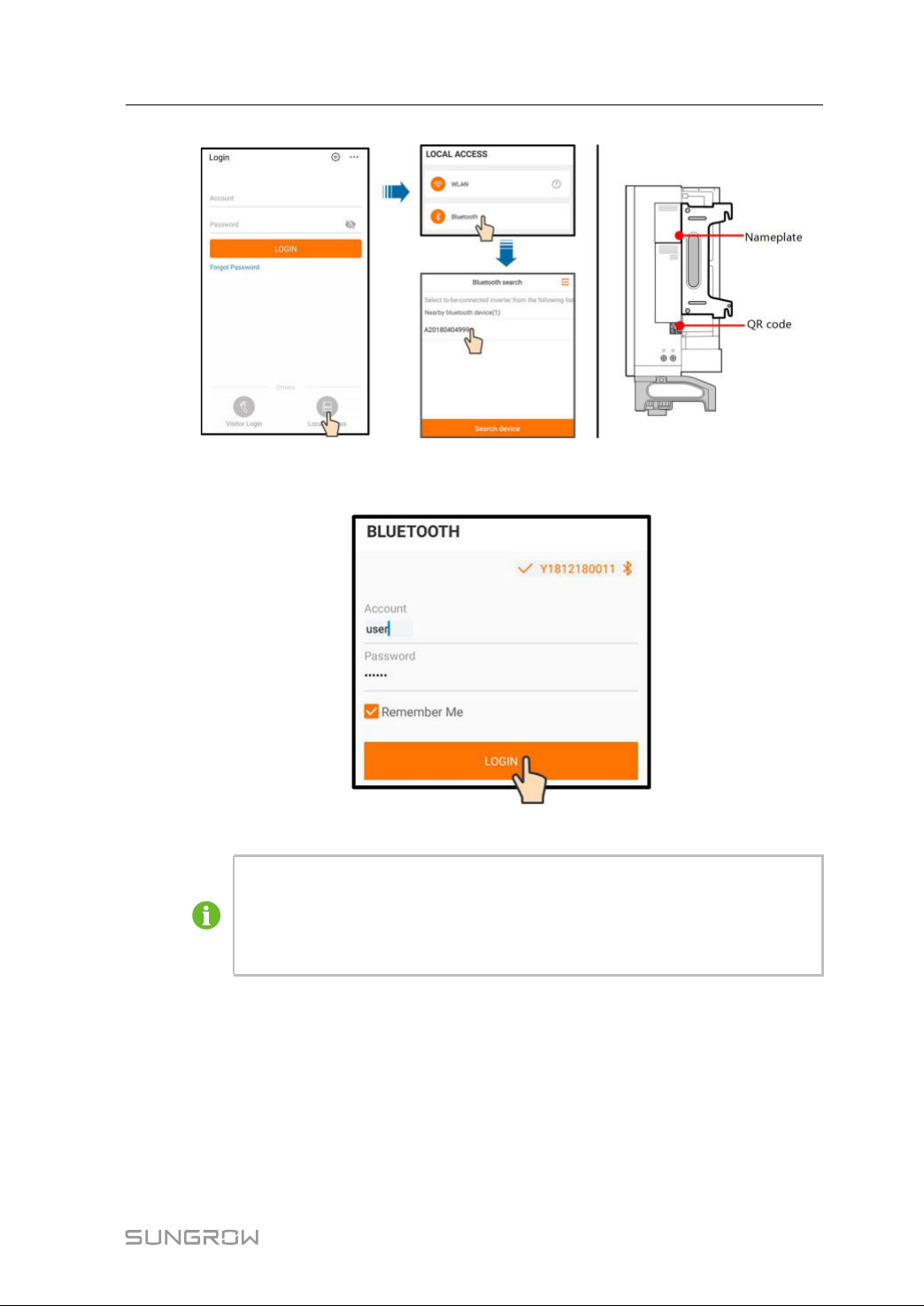
step1OpentheApptoentertheloginpage,clickon"LocalAccess"atthebottomofthepage
togotothenextpage.
step2Clickon"Bluetooth",afterwhichtheBluetoothsearchscreenpopsupautomatically,
andselecttheto-be-connectedinverteraccordingtheSNonthe nameplateofthe
inverter.TheBluetoothindicatorgetsononcetheconnectionisestablished.
Alternatively,tap"
Bluetoothconnection.
"toscantheQRcodeonthesideoftheinvertertoestablish
56
Page 67
UserManual7iSolarCloudApp
ffiigguurree77--22Bluetoothconnection
step3EntertheloginscreenaftertheBluetoothconnectionisestablished.
ffiigguurree77--33Login
Theusernameis“user”,andtheinitialpasswordis"pw1111"or"111111"
whichshouldbechangedfortheconsiderationofaccountsecurity.
Tosetinverterparametersrelatedtogridprotectionandgridsupport,contact
SUNGROWtoobtaintheadvancedaccountandcorrespondingpassword.
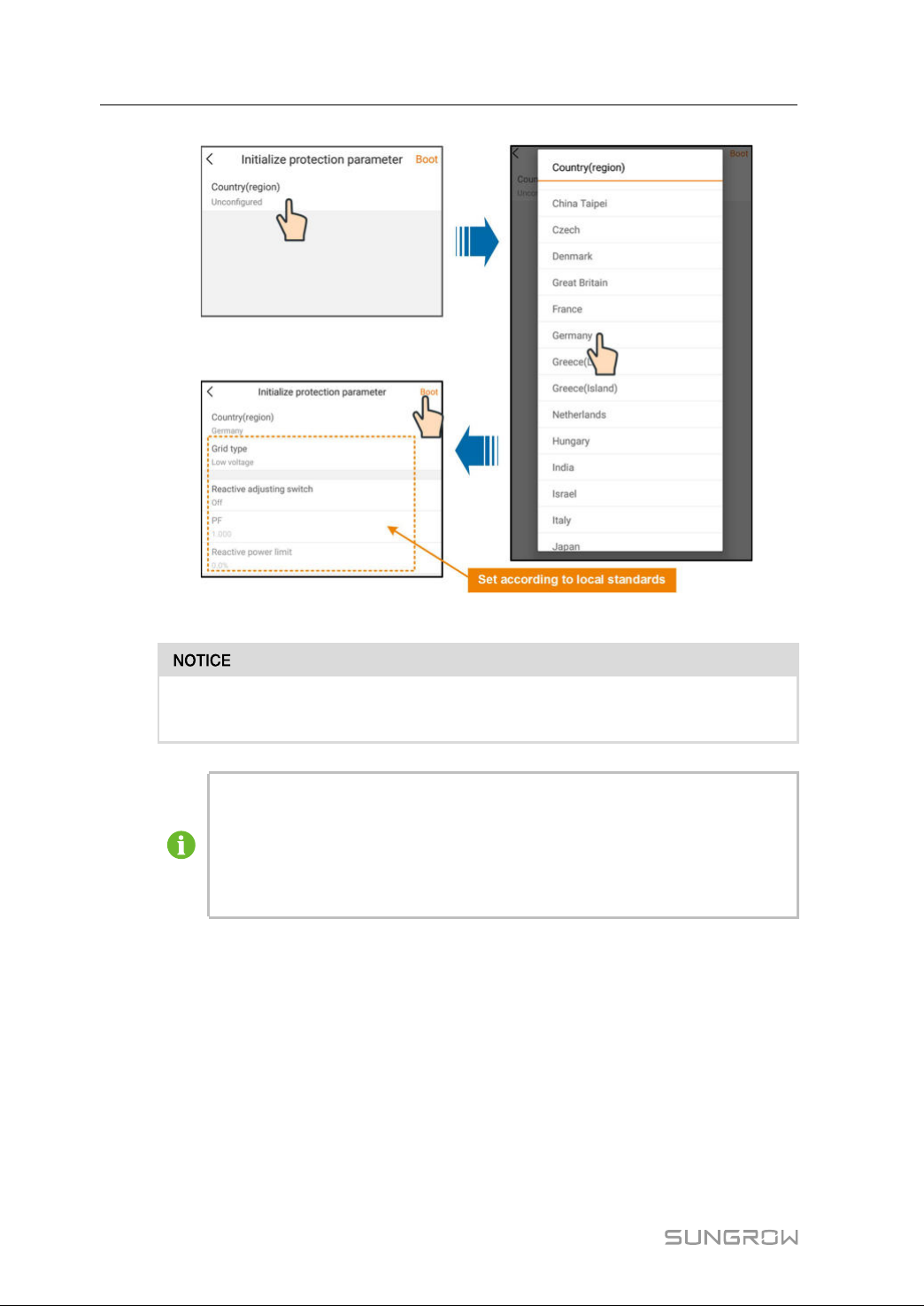
step4If the inverterisnotinitialized,youwillenterthequicksettingscreenofinitialize
protectionparameter.Afterfinishingsettingonthequicksettingscreen,click“Boot”
andthedevicewillbeinitialized.TheAppwillsendstartinstructionsandthedevicewill
startandoperate.
57
Page 68
7iSolarCloudAppUserManual
ffiigguurree77--44Initializationprotectionparameter
Resettheprotectionparametersifthecountrysettingisincorrect.Otherwise,
faultmayoccur.
IntheEuropeanregion,suchasNetherlands,Sweden,Denmark,whosegrid
codecomplieswithEN50549,selecttheparameterEN50549_1(LVgrid-
connection)orEN50549_2(MVgrid-connection).
IntheBrazilianregion,setthecountrycodeto"Brazil".Selecting"Brazil_230"
or"Brazil_240"willcausesettingfailure.
step5Iftheinverterisinitialized,theAppautomaticallyturnstoitshomepage.
----EEnndd
7.5Homepage
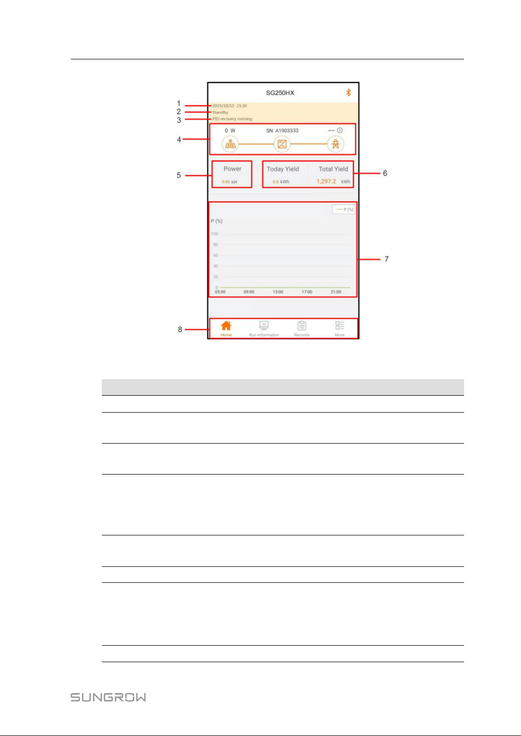
Afterlogin,thehomepageisasfollows:
58
Page 69
UserManual7iSolarCloudApp
table7-1Homepagedescription
NNoo..
DDeessiiggnnaattiioonnDDeessccrriippttiioonn
1Dateandtime
2Inverterstate
3
PIDfunction
state
4Powerflowchart
Power
5
6
generation
Real-timepowerOutputpoweroftheinverter
7Powercurve
8
NavigationbarIncluding"Home","Run-info","His-record",and"More"
ffiigguurree77--55Homepage
Systemdateandtimeoftheinverter
PresentoperationstateoftheinverterFordetails,refer
toTab.7-2Descriptionofinverterstate.
PresentstateofthePIDfunctionFordetails,refertoTab.
7-3DescriptionofPIDfunctionstate
DisplaythePVpowergenerationpower,feed-inpower,
etc.Thelinewithanarrowindicatesenergyflow
betweenconnecteddevices,andthearrowpointing
indicatesenergyflowdirection.
Todaypoweryieldandaccumulativepoweryieldofthe
inverter
Curveshowingchangeofpowerbetween5amand23
pmeveryday
(Eachpointonthecurverepresentsthepercentageof
presentinverterpowertoratedpower)
59
Page 70
7iSolarCloudAppUserManual
table7-2Descriptionofinverterstate
SSttaattee
DDeessccrriippttiioonn
Afterbeingenergized,invertertracksthePVarrays’maximum
Run
powerpoint(MPP)andconvertstheDCpowerintoACpower.Thisis
thenormaloperationmode.
StopInverterisstopped.
Inverterwillstopoperationbymanually“stop”viaapp.Inthisway,
Key-stop
inverterinternalDSPstops.Torestarttheinverter,manuallystartvia
app.
Standby
InverterentersstandbymodewhenDCsideinputisinsufficient.In
thismodeinverterwillwaitwithinthestandbyduration.
InitialstandbyTheinverterisintheinitialpower-onstandbystate.
StartingTheinverterisinitializingandsynchronizingwiththegrid.
WarningWarninginformationisdetected.
Derating
running
Scheduling
running
Theinverterderatesactivelyduetoenvironmentalfactorssuchas
temperatureoraltitude
Theinverterrunsaccordingtotheschedulinginstructionsreceived
fromthemonitoringbackground
Ifafaultoccurs,inverterwillautomaticallystopoperation,and
disconnecttheACrelay.Thefaultinformationwillbedisplayedinthe
Fault
app.Oncethefaultisremovedinrecoverytime,inverterwill
automaticallyresumerunning.
table7-3DescriptionofPIDfunctionstate
SSttaattee
PIDrecovery
running
PID
abnormity
DDeessccrriippttiioonn
TheinvertersperformPIDrecoveryactively.
ItisdetectedthattheISOimpedanceisabnormalorthePIDfunction
cannotworknormallyafterthePIDfunctionenabled.
Iftheinverterisrunningabnormally,thealarmorfaulticon
lowerrightcorneroftheinvertericoninpowerflowchart.Theusercantapthisiconto
enterthealarmorfaultscreentoviewdetailedinformationandcorrectivemeasures.
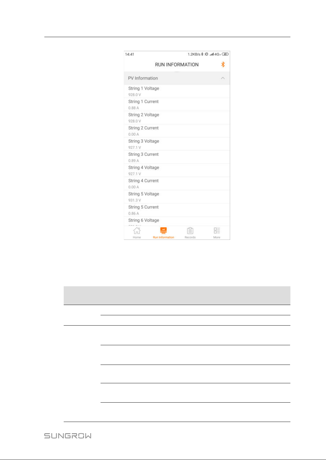
7.6RunningInformation
Tap""onthenavigationbartoentertherunninginformationscreen,asshown
inthefollowingfigure.
60
willbedisplayedinthe
Page 71
UserManual7iSolarCloudApp
ffiigguurree77--66RunningInformation
TheruninformationincludesthePVinformation,inverterinformation,inputandoutput
information.
table7-4Runinformation
CCllaassssiiffiiccaa--
ttiioonn
PV
Information
Inverter
Information
PPaarraammeetteerr
StringnVoltageTheinputvoltageofthen
StringnVoltageTheinputcurrentofthenthstring
TotalOn-grid
RunningTime
DailyOn-grid
RunningTime
NegativeVoltageto
Ground
BusVoltage
InternalAir
Temperature
DDeessccrriippttiioonn
th
string
/
/
InverterDCsidenegativetogroundvoltage
value
Voltagebetweenthepositiveandnegative
polesoftheDCsideoftheinverter
/
61
Page 72
7iSolarCloudAppUserManual
CCllaassssiiffiiccaa--
ttiioonn
Input
Output
PPaarraammeetteerr
ArrayInsulation
Resistance
CountryInformation
PowerLimitation
DDeessccrriippttiioonn
Insulationresistancevalueoftheinputsideto
theprotectionground
/
/
Mode
ReactivePower
/
Mode
TotalDCPower
MPPTxVoltageTheinputvoltageofthex
MPPTxCurrent
DCsidetotalinputpower
Theinputcurrentofthex
th
th
MPPT
MPPT
DailyYield/
MonthlyYield
AnnualYield
TotalActivePower
TotalReactive
/
/
Currentactivepowervalueoftheinverter
Currentreactivepowervalueoftheinverter
Power
TotalApparent
Currentapparentpowervalueoftheinverter
Power
TotalPowerFactorPowerfactoroftheACsideoftheinverter
GirdFrenquencyFrequencyoftheACsideoftheinverter
A-BLineVoltage
LineVoltageB-CLineVoltage
C-ALineVoltage
PhaseACurrent
PhaseCurrentPhaseBCurrent
PhaseCCurrent
7.7HistoryRecord
Tap""onthenavigationbartoenterthehistoryrecordscreen,asshowninthe
followingfigure.
62
Page 73
UserManual7iSolarCloudApp
ffiigguurree77--77Historyrecord
On"historyrecord"screen,userscancheckthealarmrecords,poweryieldrecordsand
eventrecords.
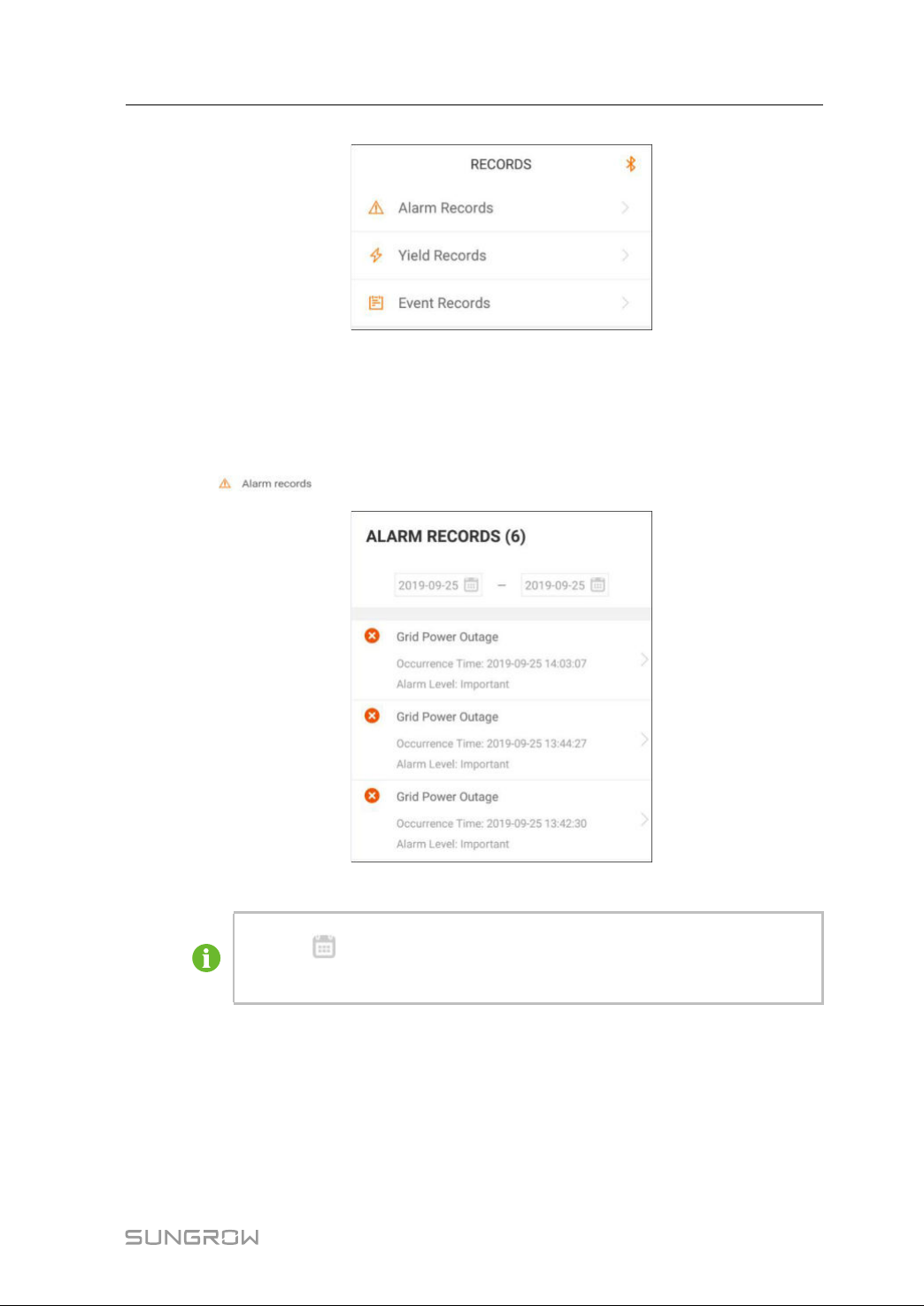
7.7.1 FaultAlarmRecords
Tap""toviewfaultandalarmrecords,asshowninthefollowingfigure.
ffiigguurree77--88Faultandalarmrecords
• Click""toselectatimesegmentandviewcorrespondingrecords.
• Theinvertercanrecordupto400latestentries.
Selectoneoftherecordsinthelistandclicktherecord,toviewthedetailedfaultinfoas
showninfollowingfigure.
63
Page 74
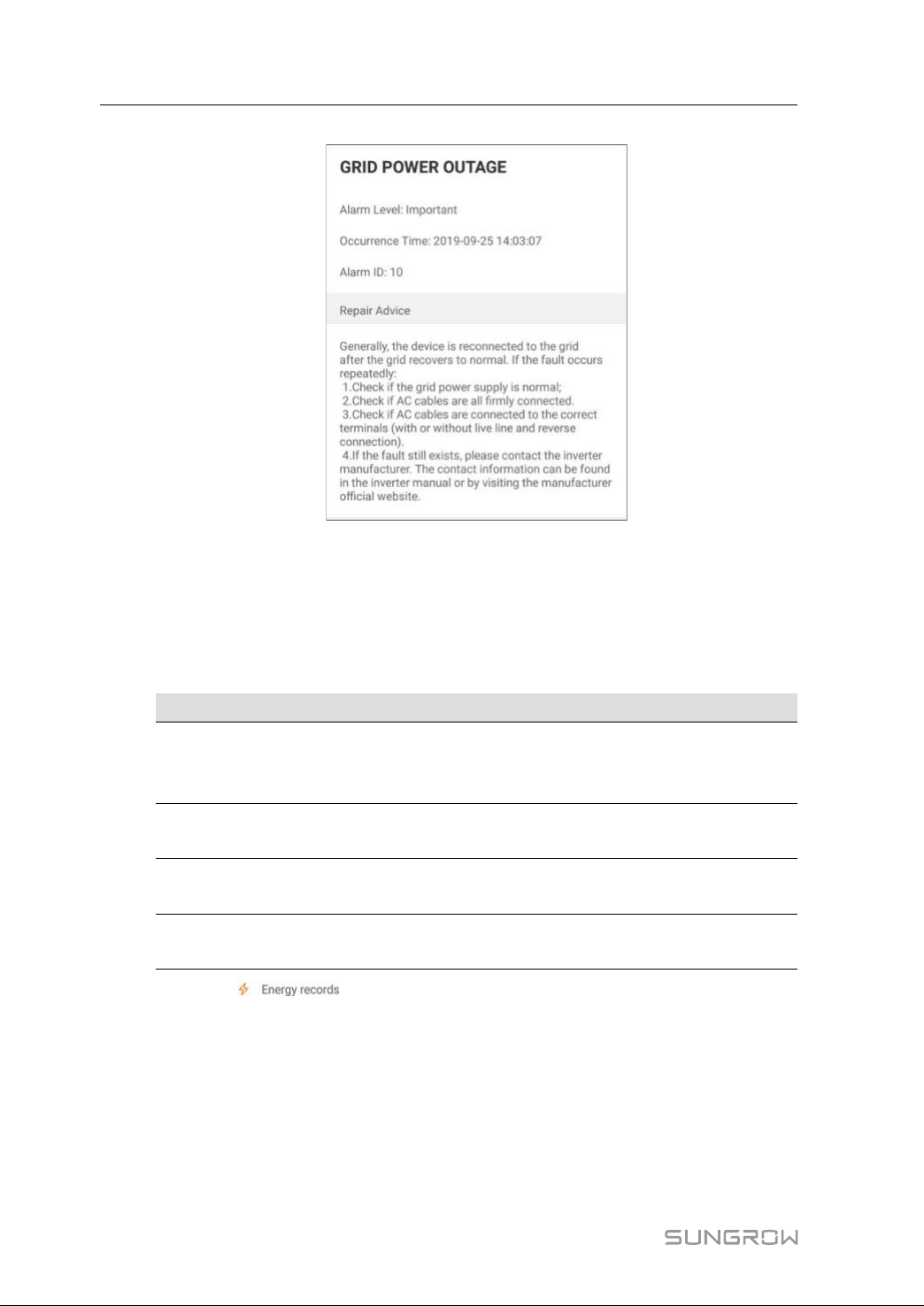
7iSolarCloudAppUserManual
ffiigguurree77--99Detailedfaultalarminfo
7.7.2 PowerYieldsRecords
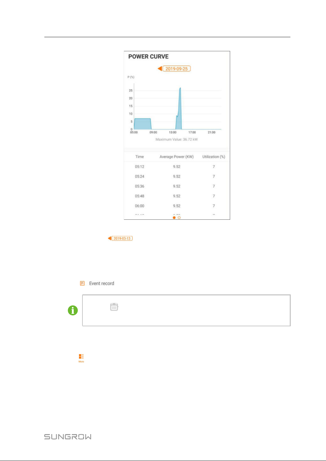
Usercanviewvarious energyrecords:power curve,dailyenergyhistogram, daily
energyhistogram,monthlyenergyhistogram,andannualenergyhistogram.
table7-5Explanationofpoweryieldsrecords
PPaarraammeetteerr
DDeessccrriippttiioonn
Showthepoweroutputfrom5amto11pminasingleday.
Powercurve
Eachpointinthecurveisthepercentageofpresentpowerand
nominalpower.
Dailyenergy
histogram
Monthlyenergy
histogram
Annualenergy
histogram
Clickthe“
Showsthepoweroutputeverydayinthepresentmonth.
Showsthepoweroutputeverymonthinayear.
Showsthepoweroutputeveryyear.
”toviewthepowercurvepageasshowninfollowingfigure.
64
Page 75
UserManual7iSolarCloudApp
Tapthetimebaronthetopofthescreentoselectatimesegmentandview
thecorrespondingpowercurve.
Swipelefttocheckthepoweryieldshistogram
7.7.3 EventRecords
Click""tovieweventrecordlist.
• Click"
• Theinvertercanatmostrecordthelatest400events.
7.8More
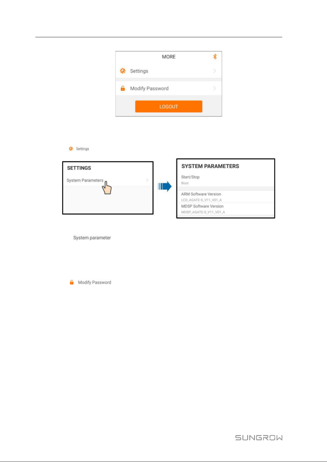
Tap""onthenavigationbartoenterthe"More"screen,asshowninthefollowing
figure.
ffiigguurree77--1100PowerCurve
"toselectatimesegmentandviewcorrespondingeventrecords.
65
Page 76
7iSolarCloudAppUserManual
ffiigguurree77--1111More
7.8.1 ParameterSetting
Tap""toentertheparametersettingscreen,asshowninthefollowingfigure.
Tap "" to enterthesystemparameter screenonwhich start/stop
instructioncanbesenttotheinverterandinformationsuchasARMversionandMDSP
versioncanbeviewed.
7.8.2 PasswordChanging
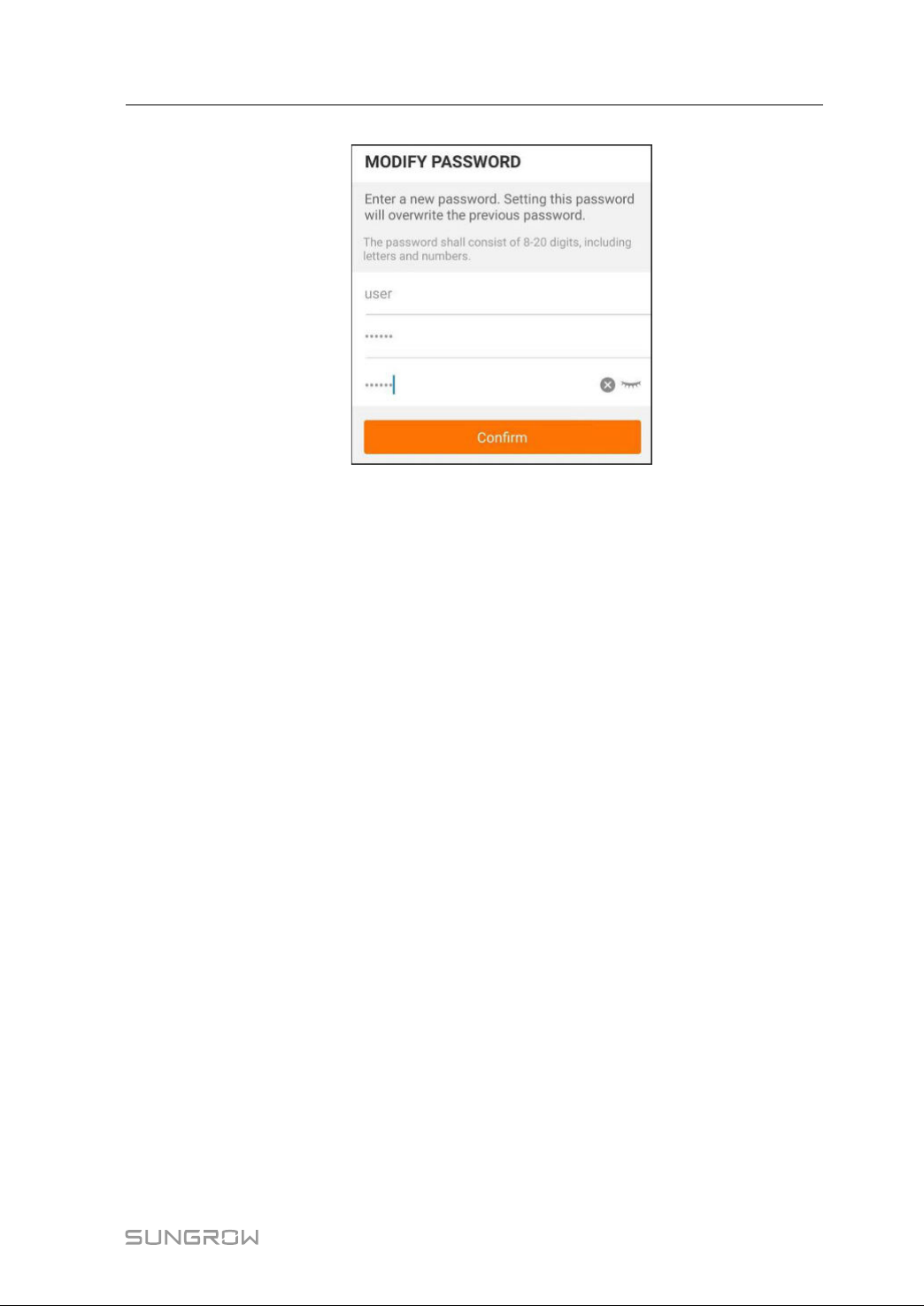
Tap""toenterthemodifypasswordscreen,asshowninthefollowing
figure.
ffiigguurree77--1122Parametersetting
66
Page 77
UserManual7iSolarCloudApp
ffiigguurree77--1133Changepassword
Thepasswordshallconsisitof8–20digits,includinglettersandnumbers.
67
Page 78
8
SystemDecommissioning
8.1DisconnectingtheInverter
Formaintenanceorotherservicework,theinvertermustbeswitchedoff.
Proceedas followstodisconnecttheinverterfromthe ACandDCpowersources.
Lethalvoltagesordamagetotheinverterwillfollowifotherwise.
step1DisconnecttheexternalACcircuitbreakerandsecureitagainstreconnection.
step2RotatetheDCswitchestothe“OFF”positionfordisconnectingallofthePVstring
inputs.
step3Waitabout5minutesuntilthecapacitorsinsidetheinvertercompletelydischarge.
step4EnsurethattheDCcableiscurrent-freeviaacurrentclamp.
step5InsertaPVterminalwrenchintothenotchandpressthewrenchwithanappropriate
forcetoremovetheDCconnector.
step6EnsurethattheACwiringterminalsarevoltage-freeviaamultimeter,andremovethe
ACwiresandcommunicationwires.
step7InstallthePVterminalwaterproofplugs.
Forfurtherdisconnectionandreconnectioninstructions,pleasevisitthe
webpageofrespectivecomponentmanufacturer.
----EEnndd
8.2DismantlingtheInverter
Riskofburninjuriesandelectricshock!
• Donottouchanyinnerlivepartsuntilatleast5minutesafterdisconnecting
theinverterfromtheutilitygridandthePVinput.
step1Referto
steps.
step2Dismantletheinverterreferringto
step3Ifnecessary,removethewall-mountingbracketfromthewall.
step4Iftheinverterwillbereinstalledinthefuture,pleasereferto
properconservation.
"5ElectricalConnection"fortheinverterdisconnectionofallcablesinreverse
"4MechanicalMounting"inreversesteps.
"3.4InverterStorage"fora
68
Page 79
UserManual8SystemDecommissioning
----EEnndd
8.3DisposaloftheInverter
Userstaketheresponsibilityforthedisposaloftheinverter.
Somepartsanddevicesoftheinverter,suchasthecapacitors,maycause
environmentalpollution.
Donotdisposeoftheproducttogetherwithhouseholdwastebutinaccordance
withthedisposalregulationsforelectronicwasteapplicableattheinstallation
site.
69
Page 80

9
TroubleshootingandMaintenance
9.1Troubleshooting
Onceafaultoccursintheinverter,thefaultinformationcanbedisplayedontheApp
interface.
Faultcodesandcheckmethodsareasfollows:
FFaauullttccooddee
002
003
DDeessccrriippttiioonn
Gridovervoltage,
Thegridvoltageis
higherthantheset
protectionvalue
Gridtransient
overvoltage,
Thetransientgrid
voltageishigherthan
thestandardvalue.
CChheecckkmmeetthhoodd
Generally,theinverterwillbereconnected
tothegridafterthegridreturnstonormal.If
thefaultoccursrepeatedly:
1.Measuretheactualgridvoltage,and
contactthelocalelectricpowercompany
forsolutionsifthegridvoltageishigherthan
thesetvalue.
2.Checkwhethertheprotectionparameters
areappropriatelysetviatheApportheLCD.
3.Checkwhetherthecross-sectionalarea
oftheACcablemeetstherequirement.
4.Ifthefaultisnotcausedbytheforegoing
reasonsandstillexists,contactSUNGROW.
Generally,theinverterwillbereconnected
tothegridafterthegridreturnstonormal.If
thefaultoccursrepeatedly,contact
SUNGROW.
70
Page 81

UserManual9TroubleshootingandMaintenance
FFaauullttccooddee
004
005
007
DDeessccrriippttiioonn
Gridundervoltage,
Thegridvoltageis
lowerthantheset
protectionvalue
Gridlowvoltage,
Thegridvoltageis
lowerthantheset
protectionvalue
ACinstantaneous
overcurrent,ACoutput
currentexceedsthe
upperlimitofthe
inverter.
CChheecckkmmeetthhoodd
Generally,theinverterwillbereconnected
tothegridafterthegridreturnstonormal.If
thefaultoccursrepeatedly:
1.Measuretheactualgridvoltage,and
contactthelocalelectricpowercompany
forsolutionsifthegridvoltageislowerthan
thesetvalue.
2.Checkwhethertheprotectionparameters
areappropriatelysetviatheApportheLCD.
3.CheckwhethertheACcableisfirmlyin
place.
4.Ifthefaultisnotcausedbytheforegoing
reasonsandstillexists,contactSUNGROW.
Generally,theinverterwillbereconnected
tothegridafterthegridreturnstonormal.If
thefaultoccursrepeatedly:
1.Measuretheactualgridvoltage,and
contactthelocalelectricpowercompany
forsolutionsifthegridvoltageislowerthan
thesetvalue.
2.Checkwhethertheprotectionparameters
areappropriatelysetviatheApportheLCD.
3.CheckwhethertheACcableisfirmlyin
place.
4.Ifthefaultisnotcausedbytheforegoing
reasonsandstillexists,contactSUNGROW.
Generally,theinverterwillbereconnected
tothegridafterthegridreturnstonormal.If
thefaultoccursrepeatedly,contact
SUNGROW.
71
Page 82

9TroubleshootingandMaintenanceUserManual
FFaauullttccooddee
008
009
010
011
DDeessccrriippttiioonn
Gridoverfrequency,
Gridfrequency
exceedstheupperlimit
oftheinverter.
Gridunderfrequency,
Gridfrequencyislower
thanthelowerlimitof
theinverter.
Gridpoweroutage,AC
switchorcircuitis
disconnected.
Deviceanomaly
CChheecckkmmeetthhoodd
Generally,theinverterwillbereconnected
tothegridafterthegridreturnstonormal.If
thefaultoccursrepeatedly:
1.Measuretheactualgridfrequency,and
contactthelocalelectricpowercompany
forsolutionsifthegridfrequencyisbeyond
thesetrange.
2.Checkwhethertheprotectionparameters
areappropriatelysetviatheApportheLCD.
3.Ifthefaultisnotcausedbytheforegoing
reasonsandstillexists,contactSUNGROW.
Generally,theinverterwillbereconnected
tothegridafterthegridreturnstonormal.If
thefaultoccursrepeatedly:
1.Checkwhetherthegridsuppliespower
reliably.
2.CheckwhethertheACcableisfirmlyin
place.
3.CheckwhethertheACcableis
connectedtothecorrectterminal(whether
thelivewireandtheNwirearecorrectlyin
place).
4.CheckwhethertheACcircuitbreakeris
connected.
5.Ifthefaultisnotcausedbytheforegoing
reasonsandstillexists,contactSUNGROW.
Waitfortheinvertertoreturntonormal.
DisconnecttheACandDCswitches,and
reconnecttheACandDCswitches15
minuteslatertorestarttheinverter.
Ifthefaultstillexists,contactSUNGROW.
72
Page 83

UserManual9TroubleshootingandMaintenance
FFaauullttccooddee
012
013
014
015
DDeessccrriippttiioonn
Excessiveleakage
current
Gridabnormal,thegrid
voltageorfrequencyis
outofthepermissible
range,andtheinverter
cannotbeconnected
tothegridnormally.
10-minutegrid
overvoltage,thegrid
voltageexceedsthe
presetACvoltageof
theinverterforalong
time.
Gridovervoltage,
Thegridvoltageis
higherthantheset
protectionvalue
CChheecckkmmeetthhoodd
1.Thefaultcanbecausedbypoorsunlight
ordampenvironment,andtheinverterwill
bereconnectedtothegridafterthe
environmentisimproved.
2.Iftheenvironmentisnormal,check
whethertheACandDCcablesarewell
insulated.
3.Ifthefaultisnotcausedbytheforegoing
reasonsandstillexists,contactSUNGROW.
Generally,theinverterwillbereconnected
tothegridafterthegridreturnstonormal.If
thefaultoccursrepeatedly:
1.Measuretheactualgridfrequency,and
contactthelocalelectricpowercompany
forsolutionsifthegridparameterexceeds
thesetvalue.
2.Ifthefaultisnotcausedbytheforegoing
reasonsandstillexists,contactSUNGROW.
Waitfortheinvertertoreturntonormal.
Ifthefaultoccursrepeatedly,contact
SUNGROW.
Generally,theinverterwillbereconnected
tothegridafterthegridreturnstonormal.If
thefaultoccursrepeatedly:
1.Measuretheactualgridvoltage,and
contactthelocalelectricpowercompany
forsolutionsifthegridvoltageishigherthan
thesetvalue.
2.Checkwhethertheprotectionparameters
areappropriatelysetviatheApportheLCD.
3.Checkwhetherthecross-sectionalarea
oftheACcablemeetstherequirement.
4.Ifthefaultisnotcausedbytheforegoing
reasonsandstillexists,contactSUNGROW.
73
Page 84

9TroubleshootingandMaintenanceUserManual
FFaauullttccooddee
016
017
019-020
021-022
024-025
030-034
DDeessccrriippttiioonn
Outputoverload,The
configuredmodule
powerisexcessively
largeandoutofthe
normaloperationrange
oftheinverter.
Gridvoltageunbalance,
theinverterdetects
unbalancedthree-
phasegridvoltage
Deviceanomaly
Deviceanomaly
Deviceanomaly
CChheecckkmmeetthhoodd
Waitfortheinvertertoreturntonormal.
Ifthefaultstillexists,contactSUNGROW.
Generally,theinverterwillbereconnected
tothegridafterthegridreturnstonormal.If
thefaultoccursrepeatedly:
1.Measuretheactualgridvoltage.Ifgrid
phasevoltagesdiffergreatly,contactthe
powercompanyforsolutions.
2.Ifthevoltagedifferencebetweenthe
threephasesiswithinthepermissiblerange
ofthelocalpowercompany,modifythegrid
voltageimbalanceparameterthroughthe
ApporLCDscreen.
3.Ifthefaultisnotcausedbytheforegoing
reasonsandstillexists,contactSUNGROW.
Waitfortheinvertertoreturntonormal.
DisconnecttheACandDCswitches,and
reconnecttheACandDCswitches15
minuteslatertorestarttheinverter.
Ifthefaultstillexists,contactSUNGROW.
Waitfortheinvertertoreturntonormal.
DisconnecttheACandDCswitches,and
reconnecttheACandDCswitches15
minuteslatertorestarttheinverter.
Ifthefaultstillexists,contactSUNGROW.
Waitfortheinvertertoreturntonormal.
DisconnecttheACandDCswitches,and
reconnecttheACandDCswitches15
minuteslatertorestarttheinverter.
Ifthefaultstillexists,contactSUNGROW.
74
Page 85

UserManual9TroubleshootingandMaintenance
FFaauullttccooddee
036
037
038
039
DDeessccrriippttiioonn
Temperatureanomaly,
Thetemperatureofthe
powermoduleis
excessivelyhighand
outofthesaferange.
Temperatureanomaly,
Thetemperatureofthe
interioroftheinverteris
excessivelyhighand
outofthesaferange.
Deviceanomaly
Lowsysteminsulation
resistance,whichis
generallycausedby
poorinsulationto
groundofthemodule/
cableorbyrainyand
dampenvironment.
CChheecckkmmeetthhoodd
1.Checkwhethertheinverterisdirectly
exposedtosunlight.Ifso,takesome
shadingmeasures.
2.Checkandcleantheairducts.
3.Checkwhetherthereis070(fan
anomaly)alarmviatheApportheLCD.Ifso,
replacethefans.
1.Checkwhethertheinverterisdirectly
exposedtosunlight.Ifso,takesome
shadingmeasures.
2.Checkandcleantheairducts.
3.Checkwhetherthereis070(fan
anomaly)alarmviatheApportheLCD.Ifso,
replacethefans.
Waitfortheinvertertoreturntonormal.
DisconnecttheACandDCswitches,and
reconnecttheACandDCswitches15
minuteslatertorestarttheinverter.
Ifthefaultstillexists,contactSUNGROW.
Waitfortheinvertertoreturntonormal.If
thefaultoccursrepeatedly:
1.CheckwhethertheISOresistance
protectionvalueisexcessivelyhighviathe
ApportheLCD,andensurethatitcomplies
withthelocalregulations.
2.Checktheresistancetogroundofthe
stringandDCcable.Takecorrection
measuresincaseofshortcircuitor
damagedinsulationlayer.
3.Ifthecableisnormalandthefaultoccurs
onrainydays,checkitagainwhenthe
weatherturnsfine.
4.Ifthefaultisnotcausedbytheforegoing
reasonsandstillexists,contactSUNGROW.
75
Page 86

9TroubleshootingandMaintenanceUserManual
FFaauullttccooddee
040-042
DDeessccrriippttiioonn
Deviceanomaly
Lowambient
temperature,the
ambienttemperatureis
043
lowerthanthe
temperatureatwhich
theinvertercan
operatenormally.
044-046
Deviceanomaly
PVinputconfiguration
047
abnormal,PVinput
modeerror
048-050
053-056
Deviceanomaly
059-060
070Fanalarm
071AC-sideSPDalarm
072DC-sideSPDalarm
076
Deviceanomaly
CChheecckkmmeetthhoodd
Waitfortheinvertertoreturntonormal.
DisconnecttheACandDCswitches,and
reconnecttheACandDCswitches15
minuteslatertorestarttheinverter.
Ifthefaultstillexists,contactSUNGROW.
Stopanddisconnecttheinverter.Restart
theinverterwhentheambienttemperature
fallswithintheoperationtemperaturerange.
Waitfortheinvertertoreturntonormal.
DisconnecttheACandDCswitches,and
reconnecttheACandDCswitches15
minuteslatertorestarttheinverter.
Ifthefaultstillexists,contactSUNGROW.
Stopanddisconnecttheinverter.Resetthe
inputmodeofthePVarray.
Waitfortheinvertertoreturntonormal.
DisconnecttheACandDCswitches,and
reconnecttheACandDCswitches15
minuteslatertorestarttheinverter.
Ifthefaultstillexists,contactSUNGROW.
1.Checkwhetherthefansoperatenormally
andareblockedbysundries.Iftheyare
blocked,clearthesundries.
2.Ifafandoesnotoperatenormally,stop
anddisconnecttheinvertertoreplacethe
fan.
ChecktheSPD,andreplaceitifnecessary.
Waitfortheinvertertoreturntonormal.
DisconnecttheACandDCswitches,and
reconnecttheACandDCswitches15
minuteslatertorestarttheinverter.
Ifthefaultstillexists,contactSUNGROW.
76
Page 87

UserManual9TroubleshootingandMaintenance
FFaauullttccooddee
DDeessccrriippttiioonn
078-081PVxabnormal
087
Electricarcdetection
moduleabnormal
088Electricarcfault
089
Electricarcdetection
disabled
CChheecckkmmeetthhoodd
1.CheckifthexthPVstringneedstobe
connected.
Ifnot,ignorethealarm;and
Ifso,checktheconnectionstatusandmake
sureitisconnectedreliably.
2.CheckifthexthDCfuseisdamaged.Ifso,
replacethefuse.
3.Ifthefaultisnotcausedbytheforegoing
reasonsandstillexists,contactSUNGROW.
*Thecode078tocode081are
correspondingtoPV1toPV4respectively.
Theinvertercanoperatenormally.
1.Checkwhethertherelatedcable
connectionandterminalsareabnormal,and
checkwhethertheambientenvironmentis
abnormal.Ifso,removethecorresponding
abnormity.
2.Ifthefaultisnotcausedbytheforegoing
reasonsandstillexists,contactSUNGROW.
1.DisconnecttheDCinputsandcheck
whetherDCcablesaredamaged,whether
thewiringterminalsorfusesarelooseorin
poorcontact,andwhethercomponentparts
areburnt.Ifso,takecorresponding
correctivemeasures.
2.Aftertakingcorrespondingmeasuresin
step1,reconnecttheDCinputs.Remove
thearcfaultthroughtheApporLCDscreen
sothattheinverterwillrecovertobenormal.
3.Ifthefaultisnotcausedbytheforegoing
reasonsandstillexists,contactSUNGROW.
1.EnabletheAFDfunctionthroughtheApp
ortheLCDscreensothattheinverterwill
recovertobenormal.
2.Ifthefaultisnotcausedbytheforegoing
reasonsandstillexists,contactSUNGROW.
77
Page 88

9TroubleshootingandMaintenanceUserManual
FFaauullttccooddee
DDeessccrriippttiioonn
Protectionself-check
105
106
116-117
failureongridside
Groundingcablefault
Deviceanomaly
220~227PVxabnormal
448~471
Stringxreverse
connectionfault
CChheecckkmmeetthhoodd
Restarttheinverterorclearthefaultthrough
theApp.
Ifthefaultstillexists,contactSUNGROW.
1.CheckwhethertheACcableiscorrectly
connected.
2.Checkwhethertheinsulationbetween
thegroundcableandthelivewireisnormal.
3.Ifthefaultisnotcausedbytheforegoing
reasonsandstillexists,contactSUNGROW.
Waitfortheinvertertoreturntonormal.
DisconnecttheACandDCswitches,and
reconnecttheACandDCswitches15
minuteslatertorestarttheinverter.
Ifthefaultstillexists,contactSUNGROW.
1.CheckifthexthPVstringneedstobe
connected.
Ifnot,ignorethealarm;and
Ifso,checktheconnectionstatusandmake
sureitisconnectedreliably.
2.CheckifthexthDCfuseisdamaged.Ifso,
replacethefuse.
3.Ifthefaultisnotcausedbytheforegoing
reasonsandstillexists,contactSUNGROW.
*Thecode220tocode227are
correspondingtoPV5toPV12respectively.
1.Checkwhetherthecorrespondingstring
isofreversepolarity.Ifso,disconnectthe
DCswitchandadjustthepolaritywhenthe
solarradiationislowandthestringcurrent
dropsbelow0.5A.
2.Ifthefaultisnotcausedbytheforegoing
reasonsandstillexists,contactSUNGROW.
*Thecode448tocode471are
correspondingtostring1tostring24
respectively.
78
Page 89

UserManual9TroubleshootingandMaintenance
FFaauullttccooddee
532-547
548-563
564-571
580-587
DDeessccrriippttiioonn
Stringxreverse
connectionalarm
Stringxoutputcurrent
anomaly
Stringxreverse
connectionalarm
Stringxoutputcurrent
anomaly
CChheecckkmmeetthhoodd
1.Checkwhetherthecorrespondingstring
isofreversepolarity.Ifso,disconnectthe
DCswitchandadjustthepolaritywhenthe
solarradiationislowandthestringcurrent
dropsbelow0.5A.
2.Ifthefaultisnotcausedbytheforegoing
reasonsandstillexists,contactSUNGROW.
*Thecode532tocode547are
correspondingtostring1tostring16
respectively.
1.Checkwhetherthecorresponding
moduleissheltered.Ifso,removethe
shelterandensuremodulecleanness.
2.Checkthemoduleforabnormalaging.
3.Ifthefaultisnotcausedbytheforegoing
reasonsandstillexists,contactSUNGROW.
*Thecode548tocode563are
correspondingtostring1tostring16
respectively.
1.Checkwhetherthecorrespondingstring
isofreversepolarity.Ifso,disconnectthe
DCswitchandadjustthepolaritywhenthe
solarradiationislowandthestringcurrent
dropsbelow0.5A.
2.Ifthefaultisnotcausedbytheforegoing
reasonsandstillexists,contactSUNGROW.
*Thecode564tocode571are
correspondingtostring17tostring24
respectively.
1.Checkwhetherthecorresponding
moduleissheltered.Ifso,removethe
shelterandensuremodulecleanness.
2.Checkthemoduleforabnormalaging.
3.Ifthefaultisnotcausedbytheforegoing
reasonsandstillexists,contactSUNGROW.
*Thecode580and587arecorresponding
tostring17andstring24respectively.
79
Page 90
9TroubleshootingandMaintenanceUserManual
9.2Maintenance
Riskofinverterdamageorpersonalinjuryduetoincorrectservice!
• Alwayskeepinmindthattheinverterispoweredbydualsources:PVstrings
andutilitygrid.
Beforeanyservicework,observethefollowingprocedure.
• DisconnecttheACcircuitbreakerandthensettheDCload-breakswitchof
theinvertertoOFF;
• Waitatleast5minutesforinnercapacitorstodischargecompletely;
• Verifythatthereisnovoltageorcurrentbeforepullinganyconnector.
Keepnon-relatedpersonsaway!
Atemporarywarningsignorbarriermustbepostedtokeepnon-related
personsawaywhileperformingelectricalconnectionandservicework.
Restarttheinverteronlyafterremovingthefaultthatimpairssafety
performance.
Astheinvertercontainsnocomponentpartsthatcanbemaintained,never
arbitrarilyreplaceanyinternalcomponents.
Foranymaintenanceneed,pleasecontactSUNGROW.Otherwise,SUNGROW
shallnotbeheldliableforanydamagecaused.
80
Page 91

UserManual9TroubleshootingandMaintenance
9.2.1 RoutineMaintenance
IItteemmMMeetthhooddPPeerriioodd
Checkthetemperatureanddustof
Systemclean
Fans
Cableentry
Electrical
Connection
theinverter.Cleantheinverter
enclosureifnecessary.
Checkiftheairinletandoutletare
normal.Cleantheairinletandoutlet,
ifnecessary.
Checkwhetherthereisfanwarning
usingApp.
Checkwhetherthereisany
abnormalnoisewhenthefanis
turning.
Cleanorreplacethefansif
necessary(seethefollowing
section).
Checkwhetherthecableentryis
insufficientlysealedorthegapis
excessivelylarge,andresealthe
entrywhennecessary.
Checkwhetherallcablearefirmlyin
place.
Checkwhetheracableisdamaged,
especiallythepartcontactingthe
metalenclosure.
Sixmonthstoayear(-
dependonthedust
contentsinair.)
Onceayear
Onceayear
Sixmonthstoayear
9.2.2 MaintenanceInstruction
CClleeaanniinnggAAiirrIInnlleettaannddOOuuttlleett
Ahugeamountofheatisgeneratedintheprocessofrunningtheinverter.Theinverter
adoptsacontrolledforced-aircoolingmethod.
Inordertomaintaingoodventilation,pleasechecktomakesuretheairinletandoutlet
arenotblocked.
Cleantheairinletandoutletwithsoftbrushorvacuumcleanerifnecessary.
81
Page 92
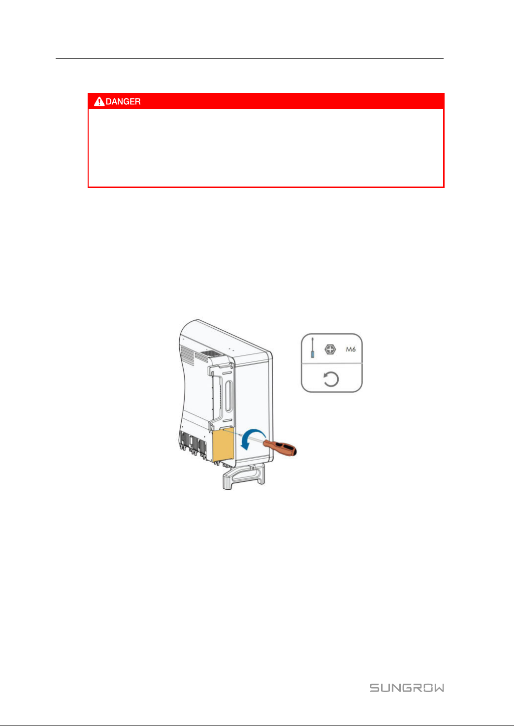
9TroubleshootingandMaintenanceUserManual
FFaannMMaaiinntteennaannccee
• Stoptheinverteranddisconnectitfromallpowersuppliesbefore
maintenance.
• Lethalvoltagestillexistsintheinverter.Pleasewaitforatleast5minutes
andthenperformmaintenancework.
• Onlyqualifiedelectricianscanmaintainthefans.
Fansinsidetheinverterareusedtocooltheinverterduringoperation.Ifthefansdonot
operatenormally,theinvertermaynotbecooleddownandinverterefficiencymay
decrease.Therefore,itisnecessarytocleanthedirtyfansandreplacethebrokenfans
intime.
Theoperationprocedureisasfollows:
step1Stoptheinverter(see
"8.1DisconnectingtheInverter").
step2Loosenthescrewonthesealingplateofthefanmodule.
step3Pressthehumpofthelatchhook,unplugthecableconnectionjointoutwards,and
loosenthescrewonthefanholder.
82
Page 93
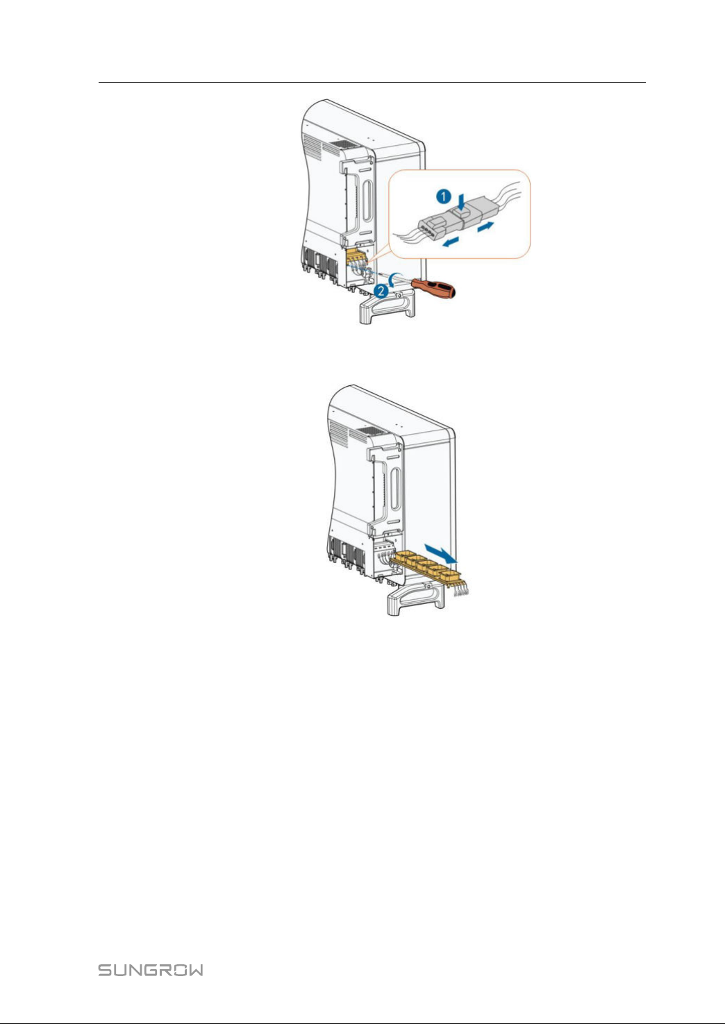
UserManual9TroubleshootingandMaintenance
step4Pulloutthefanmodule,cleanthefanswithsoftbrushorvacuumcleaner,andreplace
themwhennecessary.
step5Followthestepsabovetoremovethefanontheothersideoftheinverter.
step6Reinstallthefanbacktotheinverterinreverseorderandrestarttheinverter.
----EEnndd
83
Page 94

10
Appendix
10.1TechnicalData
PPaarraammeetteerrss
IInnppuutt((DDCC))
Max.PVinputvoltage1500V
Min.PVinputvoltage/Startup
inputvoltage
Nominalinputvoltage1160V
MPPvoltagerange600~1500V
MPPvoltagerangefornominal
power
No.ofindependentMPPinputs
Max.numberofPVstringsper
MPPT
Max.PVinputcurrent
Max.currentforinput
connector
Max.DCShort-circuitcurrent
Max.inverterbackfeedcurrent
tothearray
OOuuttppuutt((AACC))
ACoutputpower
Max.ACoutputcurrent
NominalACvoltage
ACvoltagerange
Nominalgridfrequency/Grid
frequencyrange
Totalharmonicdistortion(THD)
DCcurrentinjection
Powerfactor
Adjustablepowerfactor
Feed-inphases/Connection
phases
250kVA@30℃/225kVA@40℃/200KVA
50Hz/45~55Hz,60Hz/55~65Hz
<3%(atnominalpower)
0.8leading–0.8lagging
SSGG225500HHXX
600V/600V
860~1300V
12
2
26A*12
30A
50A*12
0A
@50℃
180.5A
3/PE,800V
680–880V
<0.5%In
>0.99
3/3
84
Page 95

UserManual10Appendix
PPaarraammeetteerrss
SSGG225500HHXX
EEffffiicciieennccyy
Max.efficiency/European
efficiency
99.0%/98.8%
PPrrootteeccttiioonn
DCreverseconnection
protection
ACshort-circuitprotection
Leakagecurrentprotection
Gridmonitoring
Groundfaultmonitoring
DCswitch/ACswitch
PVstringcurrentmonitoring
Qatnight
An-tiPIDandPIDrecovery
Yes
Yes
Yes
Yes
Yes
Yes/No
Yes
Yes
Yes
function
Overvoltageprotection
DCTypeII/ACTypeII
GGeenneerraallDDaattaa
Dimensions(W*H*D)
Weight
Isolationmethod
1051*660*363mm
99kg
Transformerless
DegreeofprotectionIP66
Nightpowerconsumption<2W
Operatingambient
temperaturerange
Allowablerelativehumidity
range(non-condensing)
Coolingmethod
Max.operatingaltitude
Display
Communication
DCconnectiontype
ACconnectiontype
5000m(>4000mderating)
MC4-Evo2(Max.6mm²,optional10mm² )
OT/DTterminal(Max.300mm²)
-30to60℃
0-100%
Smartforcedaircooling
LED,Bluetooth+APP
RS485/PLC
85
Page 96
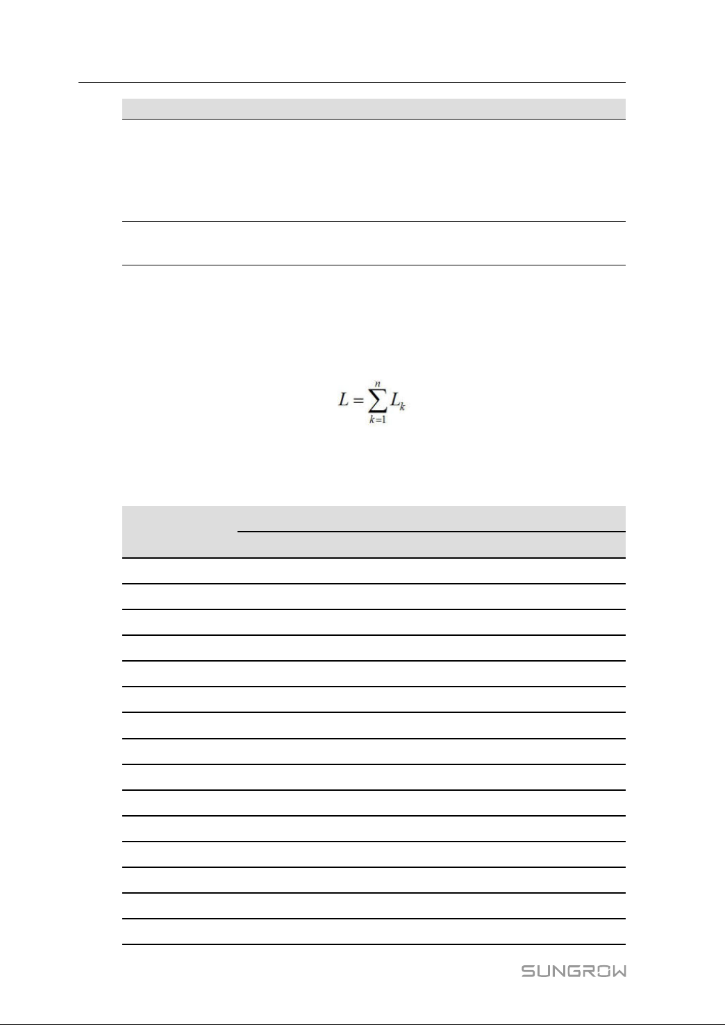
10AppendixUserManual
PPaarraammeetteerrss
IEC62109,IEC61727,IEC62116,IEC60068,IEC
61683,VDE-AR-N4110:2018,VDE-AR-N
Compliance
4120:2018,IEC61000-6-2,IEC61000-6-4,EN
50549,UNE206007-1:2013,P.O.12.3,UTEC15-
712-1:2013
GridSupport
Qatnightfunction,LVRT,HVRT,active&reactive
powercontrolandpowerrampratecontrol
10.2WringDistanceofDIDryContact
ThemaximumwiringdistanceofDCdrycontactmustmeettherequirementsinthe
tablebelow.ThewiringdistanceListhetotallengthofallDIsignalcables.
LKreferstothecablelengthbetweentheDIdrycontactterminalofthekthinverterand
thecorrespondingterminalofthe(k-1)thinverter.
table10-1Correspondencebetweennumberofinvertersandmaximumwiringdistance
SSGG225500HHXX
NNuummbbeerrooff
iinnvveerrtteerr
1166AAWWGG//11..3311mmmm
MMaaxxiimmuummwwiirriinnggddiissttaannccee((uunniitt::mm))
22
1177AAWWGG//11..002266mmmm
11303010552
265155276
343433517
432582638
526062110
621721759
718611507
816291319
914481172
1013031055
111185959
121086879
131002812
14931754
22
86
15869703
Page 97
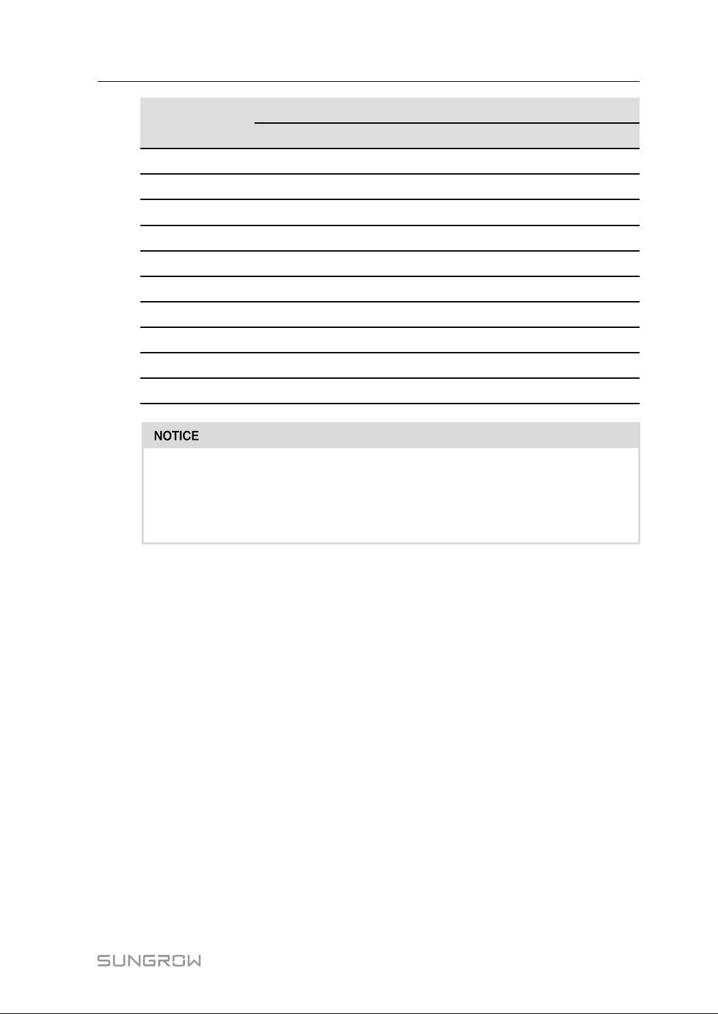
UserManual10Appendix
NNuummbbeerrooff
iinnvveerrtteerr
1166AAWWGG//11..3311mmmm
MMaaxxiimmuummwwiirriinnggddiissttaannccee((uunniitt::mm))
22
1177AAWWGG//11..002266mmmm
22
16814660
17766621
18724586
19686555
20652528
21620502
22592480
23567459
24543440
25521422
Incasethespecificationofthecableusedisnotincludedinthetableabove,
whenthereisonlyoneinverter,ensurethatthelineimpedanceoftheinputnode
islessthan300Ω;andwhentherearemultipleinvertersconnectedinthedaisy
chain,ensurethattheimpedanceislessthan300Ω/numberofinverter.
10.3QualityAssurance
Whenproductfaultsoccurduringthewarrantyperiod,SUNGROWwillprovidefree
serviceorreplacetheproductwithanewone.
EEvviiddeennccee
Duringthewarrantyperiod,thecustomershallprovidetheproductpurchaseinvoice
anddate.Inaddition,thetrademarkontheproductshallbeundamagedandlegible.
Otherwise,SUNGROWhastherighttorefusetohonorthequalityguarantee.
CCoonnddiittiioonnss
• Afterreplacement,unqualifiedproductsshallbeprocessedbySUNGROW.
• ThecustomershallgiveSUNGROWareasonableperiodtorepairthefaultydevice.
EExxcclluussiioonnooffLLiiaabbiilliittyy
Inthefollowingcircumstances,SUNGROWhastherighttorefusetohonorthequality
guarantee:
• Thefreewarrantyperiodforthewholemachine/componentshasexpired.
• Thedeviceisdamagedduringtransport.
87
Page 98

10AppendixUserManual
• Thedeviceisincorrectlyinstalled,refitted,orused.
• Thedeviceoperatesinharshenvironment,asdescribedinthismanual.
• Thefaultordamageiscausedbyinstallation,repairs,modification,ordisassembly
performedbyaserviceproviderorpersonnelnotfromSUNGROW.
• Thefaultor damageis causedby theuse ofnon-standard ornon-SUNGROW
componentsorsoftware.
• The installationanduserangearebeyondstipulations ofrelevant international
standards.
• Thedamageiscausedbyunexpectednaturalfactors.
Forfaultyproductsinanyofabovecases,ifthecustomerrequestsmaintenance,paid
maintenanceservicemaybeprovidedbasedonthejudgmentofSUNGROW.
10.4ContactInformation
Weneedthefollowinginformationtoprovideyouthebestassistance:
• Typeofthedevice
• Serialnumberofthedevice
• Faultcode/name
• Briefdescriptionoftheproblem
China
SungrowPowerSupplyCo.,Ltd
Hefei
+8655165327834
Brazil
SungrowDoBrasil
SaoPaulo
+551123661957
Germany
SungrowDeutschlandGmbH
München
+4989324914761
Australia
SungrowAustraliaGroupPty.Ltd.
Sydney
+61299221522
France
SungrowFrance–SiegeSocial
Paris
Greece
ServicePartner–SurveyDigital
+302106044212
88
Page 99

UserManual10Appendix
India
Sungrow(India)PrivateLimited
Gurgaon
+9108041201350
Japan
SungrowJapanK.K.
Tokyo
+81362629917
Malaysia
SungrowSEA
SelangorDarulEhsan
+60198973360
Thailand
SungrowThailandCo.,Ltd.
Bangkok
+66891246053
Romania
ServicePartner-Elerex
+40241762250
UK
SungrowPowerUKLtd.
MiltonKeynes
+44(0)0908414127
Vietnam
SungrowVietnam
Hanoi
+84918402140
Italy
SungrowItaly
Milano
Korea
SungrowPowerKoreaLimited
Seoul
+827077191889
Philippines
SungrowPowerSupplyCo.,Ltd
MandaluyongCity
+639173022769
Spain
SungrowIbéricaS.L.U.
Navarra
Turkey
SungrowDeutschlandGmbHTurkey
IstanbulRepresentativeBureau
Istanbul
+902127318883
U.S.A,Mexico
SungrowUSACorporation
PhoenixArizona
+18337476937
89
Page 100

Add: No.1699 Xiyou Rd.,New & High Technology Industrial Development Zone, 230088,Hefei, P. R. China.
Tel: +86 551 6532 7834 / 6532 7845Web: www.sungrowpower.com E-mail: [email protected]
Sungrow Power Supply Co., Ltd.
Specifications are subject to changes without advance notice.
 Loading...