

Page 1

LLooggggeerr33000000DDaattaa LLooggggeerrUUsseerr
MMaannuuaallLLooggggeerr33000000--UUEENN--VVeerr1177--
220011990044
Logger3000-UEN-Ver17-201904
Logger3000
DDaattaa LLooggggeerr
UUsseerr MMaannuuaall
Page 2

Page 3

CCoonntteennttss
1 About this Manual ....................................................................................... 1
1.1 Validity ......................................................................................................... 1
1.2 Target Group................................................................................................ 1
1.3 Symbol Explanations .................................................................................... 1
1.4 How to Use This Manual............................................................................... 3
2 Safety Instructions ...................................................................................... 4
3 Product Introduction ................................................................................... 6
3.1 Function Description .................................................................................... 6
3.2 Application scenario ..................................................................................... 7
3.3 Appearance ................................................................................................. 9
3.3.1 Appearance........................................................................................ 9
3.3.2 Dimensions ...................................................................................... 10
4 Installation Flow ......................................................................................... 11
5 Unpacking and Storage ........................................................................... 13
5.1 Scope of Delivery ....................................................................................... 13
5.2 Identifying the Logger3000 ........................................................................ 14
5.3 Checking upon Receiving ........................................................................... 14
5.4 Storage...................................................................................................... 15
6 Mechanical Installation ............................................................................ 16
6.1 Location Selection...................................................................................... 16
6.2 Installation Tools......................................................................................... 16
6.3 Installing Logger3000................................................................................. 17
6.3.1 Wall-Mounted Installation ................................................................. 17
6.3.2 Rack-mounted Installation ................................................................ 19
7 Electrical Connection ............................................................................... 21
7.1 Safety Instructions...................................................................................... 21
7.2 Port Introduction......................................................................................... 21
7.3 Overview.................................................................................................... 23
7.4 RS485 Port ................................................................................................ 23
7.4.1 Connecting to the Device with RS485 Port ........................................ 23
I
Page 4

7.4.2 Connecting to the Device with RJ45 Port........................................... 25
7.4.3 Connecting to the Meteo Station ....................................................... 26
7.4.4 Connecting to the Energy Meter........................................................ 27
7.5 Ethernet Port .............................................................................................. 28
7.6 PLC Port..................................................................................................... 29
7.7 Connecting to the AC Power Supply ........................................................... 30
7.8 Connecting to the DC Power Supply ........................................................... 31
7.9 Earthing Connection................................................................................... 32
8 Commissioning ........................................................................................... 33
8.1 Inspection before Commissioning .............................................................. 33
8.2 Commissioning Steps................................................................................. 33
9 Web Interface ............................................................................................. 34
9.1 Running Requirements ............................................................................... 34
9.2 Preparation before Login............................................................................ 34
9.3 Login Steps ................................................................................................ 34
9.4 Web Interface ............................................................................................ 35
9.5 Web Menus ............................................................................................... 36
9.6 Operation Flow........................................................................................... 36
9.7 Monitoring.................................................................................................. 37
9.7.1 View Real-Time Data ........................................................................ 37
9.7.2 Single-Parameter Setting .................................................................. 38
9.7.3 Batch Setting .................................................................................... 38
9.7.4 Parameter Readback ........................................................................ 38
9.7.5 Checking the Parameter Setting Log................................................. 38
9.8 Device Management .................................................................................. 38
9.8.1 Searching Device ............................................................................. 39
9.8.2 Device Operation .............................................................................. 41
9.8.3 Firmware Upgrade ........................................................................... 43
9.9 System Setting ........................................................................................... 43
9.9.1 SystemTime Setting .......................................................................... 43
9.9.2 Serial Port Setting ............................................................................. 44
9.9.3 Network Setting ................................................................................ 44
9.9.4 Restarting......................................................................................... 45
9.9.5 Modbus Service ............................................................................... 45
9.9.6 IEC104 Service Settings ................................................................... 46
9.9.7 IEC104 Main Protocol Settings (Optional).......................................... 46
II
Page 5

9.9.8 Cloud Service Setting........................................................................ 47
9.9.9 Country and Region Setting .............................................................. 49
9.9.10 About ............................................................................................. 49
9.10 Maintenance............................................................................................ 49
10 Grid Dispatching ...................................................................................... 51
10.1 Function Description ................................................................................ 51
10.2 Grid Dispatching Plans ............................................................................. 51
10.3 EMU Setting............................................................................................. 52
10.4 Local Power Regulation............................................................................ 54
10.5 BDEW...................................................................................................... 56
11 Maintenance ............................................................................................. 57
11.1 Safety Instructions.................................................................................... 57
11.2 Maintenance List...................................................................................... 58
12 Troubleshooting ....................................................................................... 59
12.1 Safety Instructions ................................................................................... 59
12.2 Common Faults and Corrective Measures................................................ 59
13 FAQ .............................................................................................................. 64
14 Appendix A: Technical Data ................................................................. 66
15 Appendix B: Related Drawings ........................................................... 67
16 Appendix C: General Information ....................................................... 68
16.1 Quality Guarantee .................................................................................... 68
16.2 Contact Information ................................................................................. 68
III
Page 6

Page 7

1 About this Manual
1.1 Validity
This manual is valid for the following data loggers:
• Logger3000
1.2 Target Group
This manual is applicable to technical personnel who are responsible for the installation,
operation and maintenance of the Logger3000 and to users who need to perform daily
operation. Readers should have the following qualifications:
• Have some knowledge of electrical and electric cabling and mechanical knowledge;
and be familiar with electrical and mechanical diagrams.
• Be familiar with the PV grid-connected power generation system and its working
principle.
• Have received professional training in installing and commissioning of the electrical
devices.
• Be capable of handling the danger or emergency that may occur during installation
or commissioning.
• Be familiar with the national/local standards and regulations.
• Be familiar with the description in this manual.
Only personnel meeting the foregoing requirements can conduct installation,
maintenance, and troubleshooting. Unauthorized personnel is prohibited to perform any
operation on the device.
1.3 Symbol Explanations
WWaarrnniinngg LLaabbeell
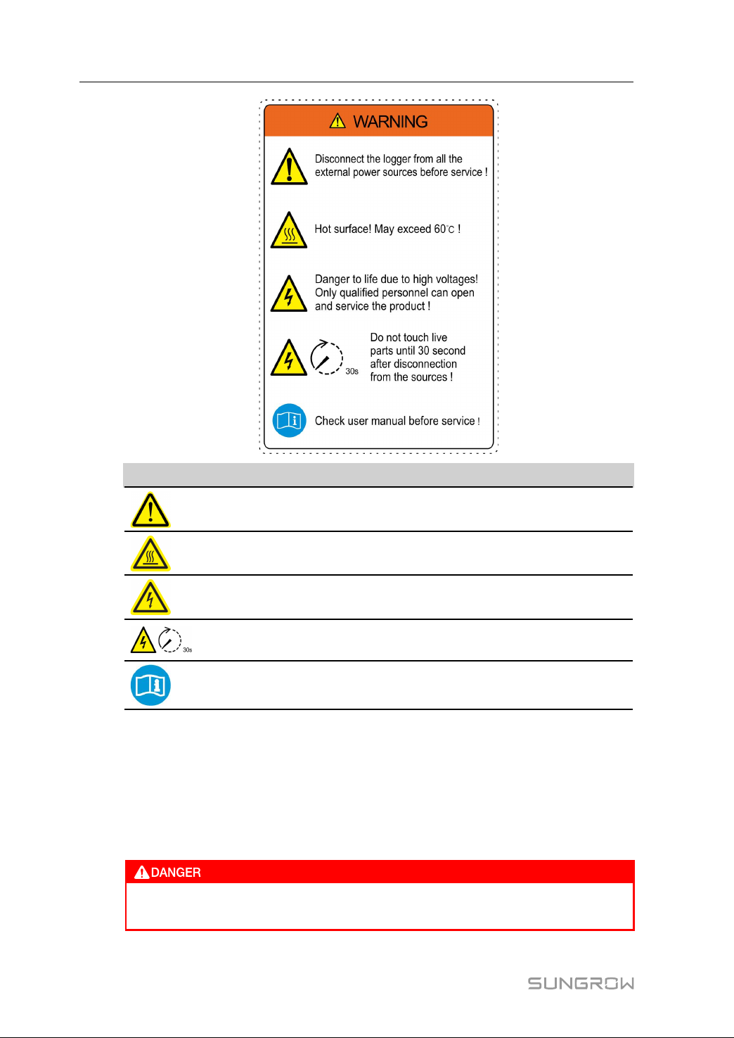
Warning label on enclosure of the Logger3000 is as follows:
1
Page 8
1 About this Manual User Manual
SSyymmbboollss EExxppllaannaattiioonn
Disconnect the Logger3000 from all the external power sources before
service!
Hot surface! Do not touch!
Risk of electric shock! If not avoided, lethal hazard can be caused.
Do not touch live parts until 30second after disconnection from the
sources!
Check user manual before service!
SSyymmbboollss
This manual contains important safety and operational instructions that must be
accurately understood and respected during the installation and maintenance of the
equipment.
To ensure the optimum use of this manual, note the following explanations of the
symbols used.
DANGER indicates a hazard with a high level of risk which, if not avoided, will
result in death or serious injury.
2
Page 9
User Manual 1 About this Manual
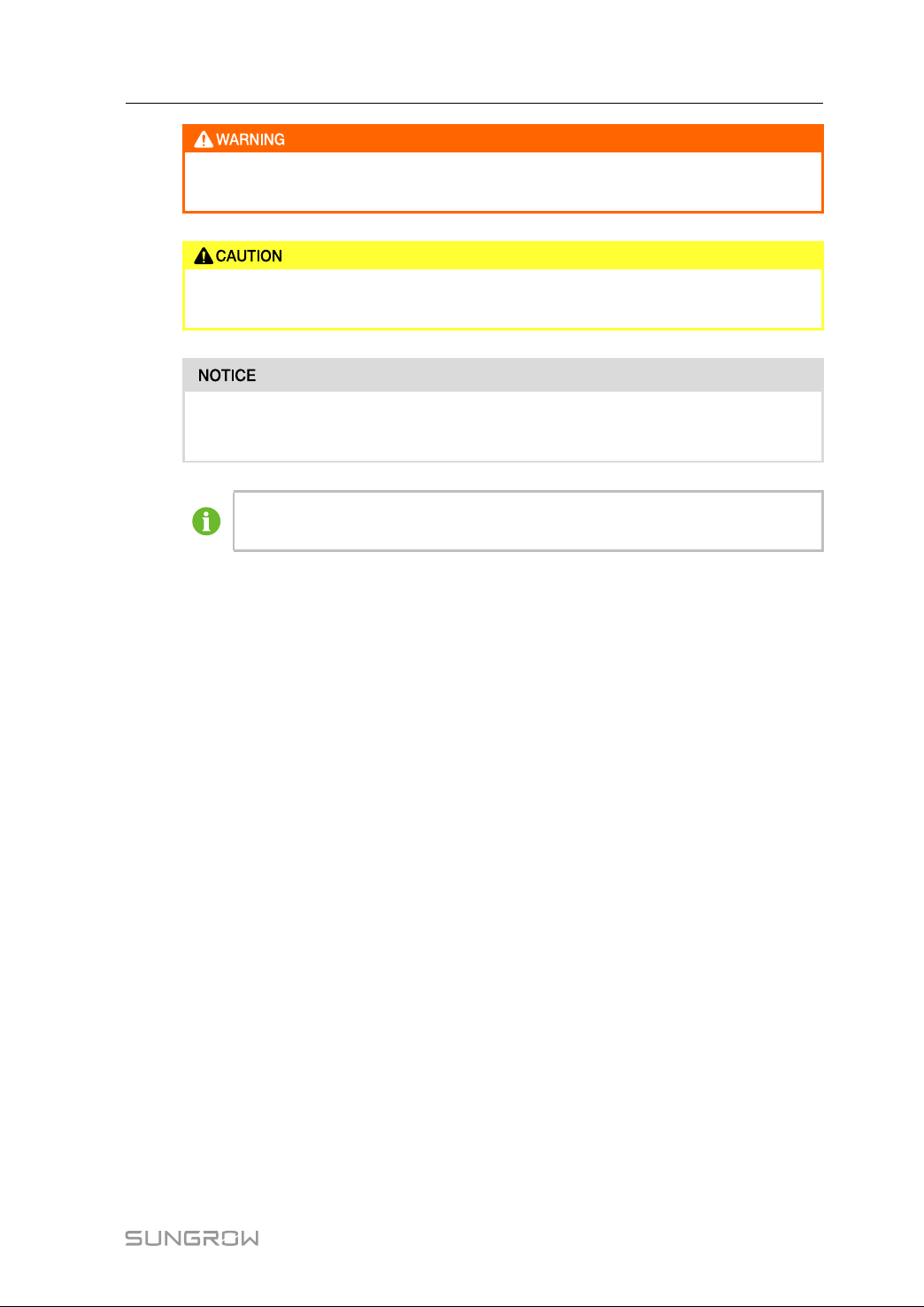
WARNING indicates a hazard with a medium level of risk which, if not avoided,
could result in death or serious injury.
CAUTION indicates a hazard with a low level of risk which, if not avoided, could
result in minor or moderate injury.
NOTICE indicates a situation which, if not avoided, could result in equipment or
property damage.
NOTE indicates additional information, emphasized contents or tips to help
you solve problems or save time.
1.4 How to Use This Manual
Read this manual carefully before performing operation on the device. This manual
must be stored at hand and available at all times.
All rights reserved including the pictures, symbols, and markings used in this manual.
Any reproduction or disclosure, even partially, of the contents of this manual is strictly
prohibited without prior written authorization of SUNGROW. The content of the manual
will be periodically updated or revised as per the product development. It is probably
that there are changes in manuals for the subsequent module edition. If there any
mismatch between the product and its manual, the actual product shall prevail and the
manual of the latest version can be obtained from SUNGROW.
3
Page 10
2
Safety Instructions
This chapter mainly introduces safety instructions that need to be respected during the
operation of Logger3000.
The Logger3000 has been designed and tested strictly according to international safety
regulations. As electrical and electronic equipment, the Logger3000 must be installed,
commissioned, operated, and maintained in strict accordance with related safety
instructions. Incorrect operation or misuse of the device may cause:
• damage to personnel safety of the operators or the third party
• damage to the Logger3000 or other properties belong to the operators or the third
party
Therefore, the following safety instructions must be read and always kept in mind prior
to any work. All detailed work-related safety warnings and notes will be specified at the
critical points in corresponding chapter.
All operations and electrical work must only be performed by qualified
personnel.
BBeeffoorree IInnssttaallllaattiioonn
After receiving the device, please check if there is damage caused during
transport. Contact SUNGROW or the forwarding company once any problem is
found.
The related operators must be familiar with the safety instructions in this manual
and other safety regulations about the installation, operation and maintenance
of the Logger3000.
Move, transport, install, operate, and maintain the Logger3000 correctly and
appropriately.
DDuurriinngg IInnssttaallllaattiioonn
The Logger3000 can only be used as described in this manual. Altering the
product without authorization or using spare parts not sold or recommended by
SUNGROW may lead to fire, electric shock or other damages.
4
Page 11
User Manual 2 Safety Instructions
Disconnect all electrical connections and the upstream input switch and make
sure the Logger3000 is voltage-free during installation.
MMaaiinntteennaannccee aanndd RReeppllaacceemmeenntt
The maintenance of the Logger3000 can only be performed by qualified
personnel from SUNGROW or other qualified personnel.
User can never maintain or replace the modules and other parts. Serious
personal injury or property loss may follow if otherwise.
Never replace the internal components of the Logger3000 without
authorization. SUNGROW shall not be held liable for any possible damage
caused by ignorance of this warning.
5
Page 12

3 Product Introduction
3.1 Function Description
The Logger3000 is equipped with the following functions:
SSuuppppoorrtt ooff DDeevviiccee CCoonnnneeccttiioonn
The Logger3000 can be connected to devices in the PV system via an RS485 bus, and
it can be also connected to SUNGROW string inverter equipped with the PLC
communication function through the PLC cable. The Logger3000 can store and process
device information as well as convert data communication protocol.
MMaannaaggeemmeenntt ooff CCoommmmuunniiccaattiioonn DDeevviiccee
The Logger3000 can centrally manage devices connected to it, including parameter
setting, firmware upgrade, etc, which makes onsite maintenance more convenient.
CCoonnffiigguurraattiioonn tthhrroouugghh WWEEBB IInntteerrffaaccee
Users can set system time, network, serial port, etc. and maintain the protocol point
table through the embedded WEB interface of the Logger3000.
DDaattaa FFoorrwwaarrddiinngg SSeerrvviiccee
The Logger3000 can forward collected data to cloud platform, for example, iSolarCloud.
PPrroottooccooll CCoonnvveerrssiioonn SSeerrvviiccee
The Logger3000 provides protocol conversion service, including converting
ModbusRTU into IEC104, MQTT, etc.
GGrriidd DDiissppaattcchhiinngg
The Logger3000 can receive and execute dispatching instructions from the grid,
including remote IEC104 instructions, remote dispatching from Japan utility power
company, and AI/DI dispatching control instructions.
The Logger3000 can perform active power control and reactive power regulation on the
inverter connected to it.
LLooccaall DDiissppaattcchhiinngg
The Logger3000 can receive and execute local dispatching instructions, including
delivering fixed value, energy meter closed-loop dispatching, etc.
II--VV CCuurrvvee SSccaannnniinngg
The Logger3000 can perform I-V curve scanning on SUNGROW inverter, and users can
view scanning result via iSolarCloud or Insight. For detailed description of the I-V curve
scanning, refer to the manual of iSolarCloud or Insight.
6
Page 13
User Manual 3 Product Introduction
3.2 Application scenario
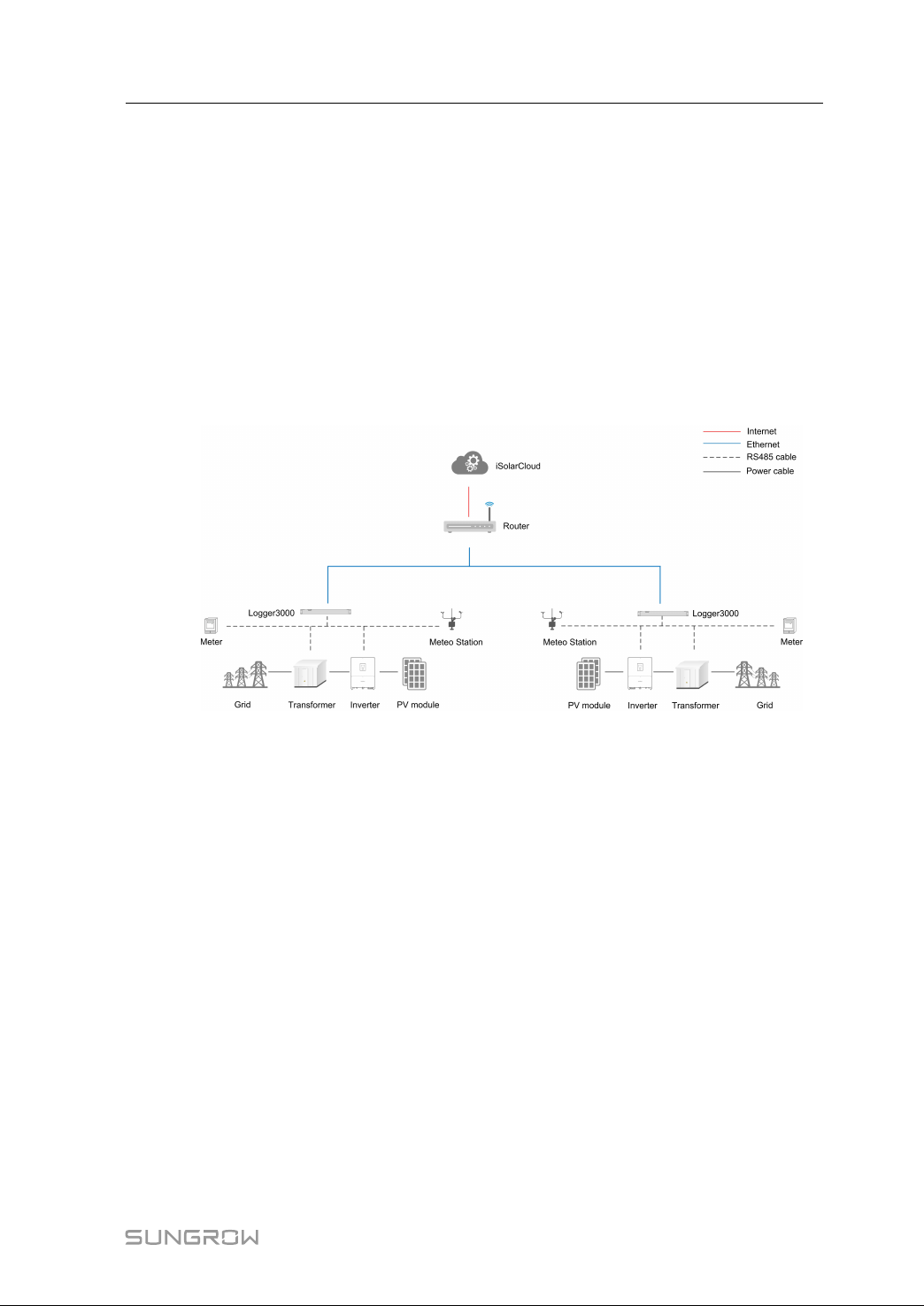
The Logger3000 is connected to the inverter, transformer, Meteo Station, and energy
meter in the PV system via RS485 bus, or it can be connected to SUNGROW string
inverter equipped with PLC communication function through PLC (power line carrier
communication) bus.
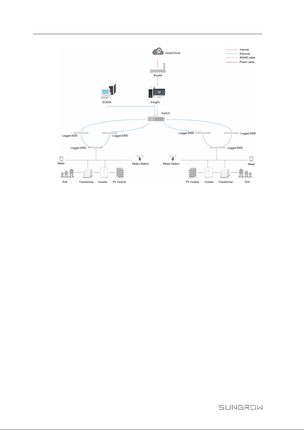
The Logger3000 sends the collected data to Insight or a third-party server via a core
switch, and then the background sends the data to iSolarCloud through a router.
CCoonnnneeccttiioonn tthhrroouugghh SSoorree SSwwiittcchh
The following figures shows how the Logger3000 is connected to the Insight or
iSolarCloud through a core switch.
ffiigguurree 33--11 Ring networking
7
Page 14
3 Product Introduction User Manual
ffiigguurree 33--22 Star networking
8
Page 15
User Manual 3 Product Introduction
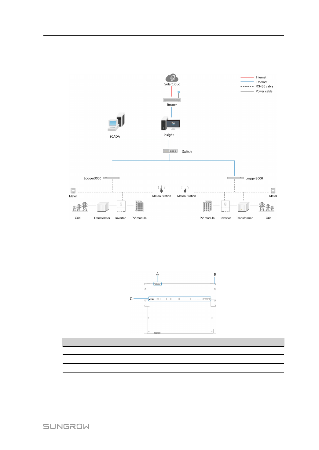
CCoonnnneeccttiioonn tthhrroouugghh RRoouutteerr
As shown in the figure below, the Logger3000 can be directly connected to the
iSolarCloud through a router.
3.3 Appearance
3.3.1 Appearance
Appearance of the Logger3000 is shown in the following figure.
NNoo.. DDeessccrriippttiioonn
A Indicator
B Mounting ear
C
Wiring terminal
9
Page 16
3 Product Introduction User Manual
IInnddiiccaattoorr
IInnddiiccaa--
NNaammee
DDeessccrriippttiioonn
ttoorr
PWR Power
indicator
RUN Running
On: power supply is normal; Off: power supply is
abnormal
Flashing: running is normal; Off: running is abnormal
indicator
BLE Bluetooth
Reserved
indicator
FAULT Fault indicator
On: fault occurs in connected inverter; Off: connected
inverter is free of fault
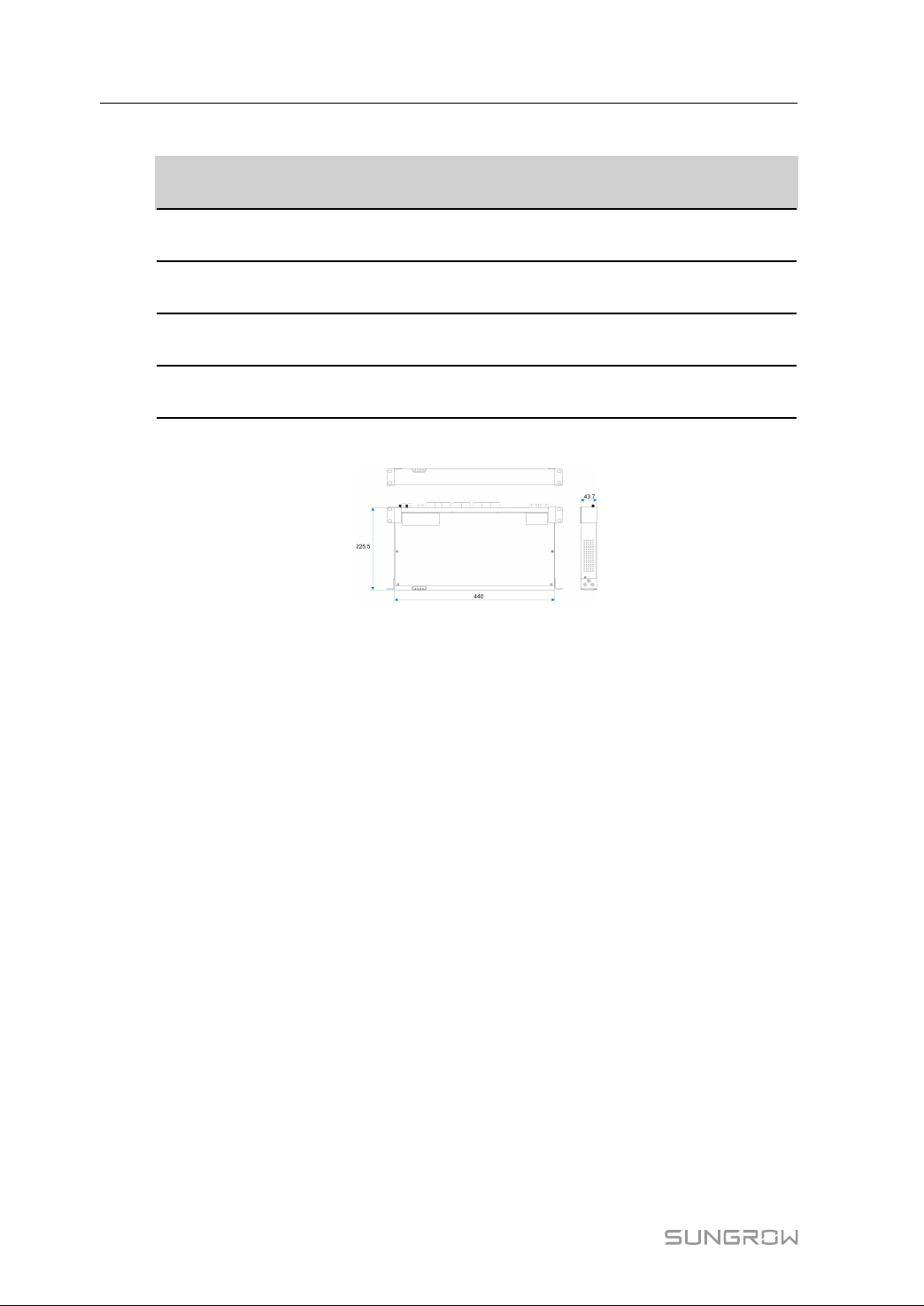
3.3.2 Dimensions
10
Page 17
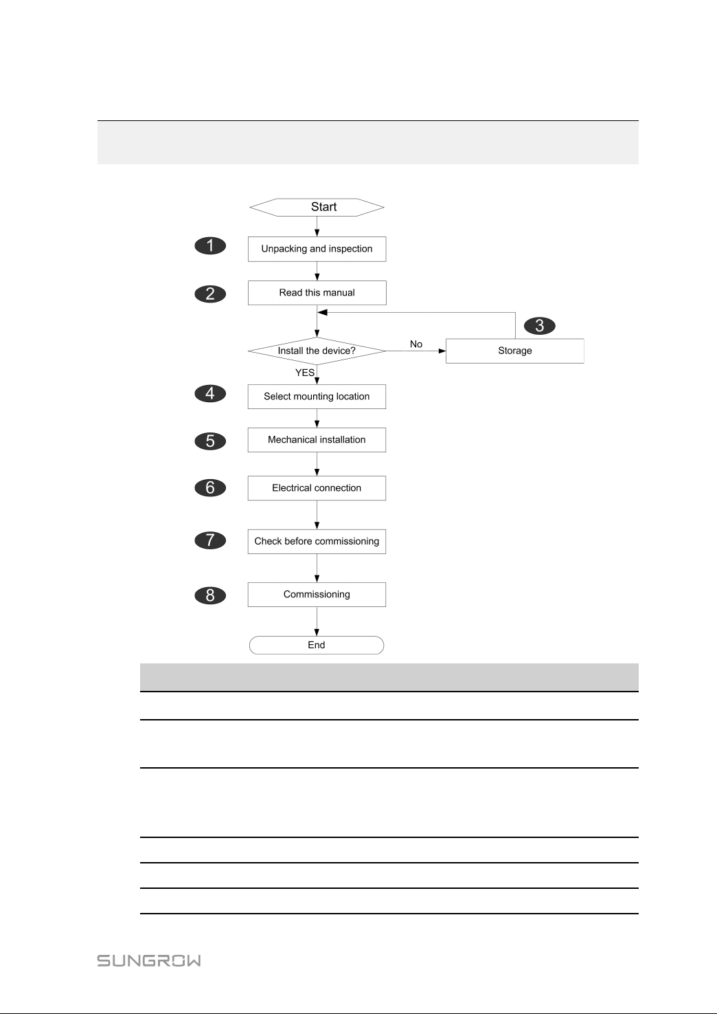
4 Installation Flow
The following figure shows the overall installation flow of Logger3000.
NNoo.. PPrroocceedduurree
Unpacking and inspection
1
Read the user manual,
2
especially "Safety Instructions"
Store the Logger3000 properly
if it is not to be installed
3
immediately
Installation location selection "6.1 Location Selection"
4
5 Mechanical installation
6 Electrical installation
RReeffeerreennccee cchhaapptteerr
"5.1 Scope of Delivery"
"2 Safety Instructions"
"5.4 Storage"
"6 Mechanical Installation"
"7 Electrical Connection"
11
Page 18

4 Installation Flow User Manual
NNoo.. PPrroocceedduurree
Check before commissioning "8.1 Inspection before Commissioning"
7
Commissioning "8.2 Commissioning Steps"
8
RReeffeerreennccee cchhaapptteerr
12
Page 19
5
Unpacking and Storage
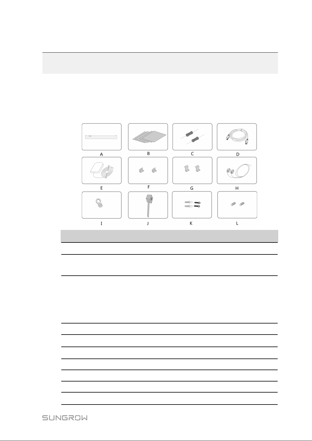
5.1 Scope of Delivery
Check the scope of delivery for completeness according to the packing list. The
following items should be included.
NNoo.. NNaammee
Logger3000
A
B Documents
Communication terminal
C
resistor
D Ethernet cable 1x2m
E GPS antenna
Mounting ear
F
Bottom supporter
G
H PLC cable 2 x1m
I OT terminal RNBL5-4
Nylon cable tie
J
DDeessccrriippttiioonn
-
Quick User Manual, quality certificate, packing list,
product test report, and warranty card
(Note: if there are more than 15 devices
connected on the RS485 bus, it is recommended
to connect a 120Ω terminal resistor in parallel on
the A and B lines at the head or tail end of the
bus)
Optional
2
2
Used to tie cables
13
Page 20
5 Unpacking and Storage User Manual
NNoo.. NNaammee
Tapping screw assembly 8, including ST4.8x19 expansion bolts and
K
L Fastener assembly
DDeessccrriippttiioonn
tapping screws, used for wall-mounted
installation
6, M4x8 cross recessed countersunk head
screws, used to anchor the mounting ears to the
Logger3000
5.2 Identifying the Logger3000
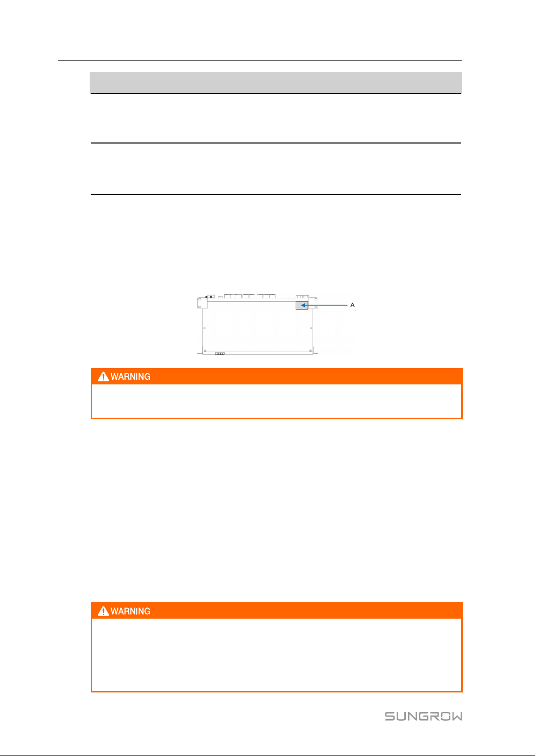
The type and key technical parameters of the Logger3000 can be found on the
nameplate. The nameplate is attached to the upper right corner of the Logger3000,
shown by A in the figure below.
The nameplate contains important parameters. Ensure it is intact and clearly
legible.
5.3 Checking upon Receiving
The Logger3000 is thoroughly inspected and packed before delivery, but damage may
be still caused during transport. Check the following items carefully once receiving the
Logger3000.
• Check the scope of delivery for completeness according to "5.1 Scope of Delivery".
• Ensure that the device type is correct.
• Check the device thoroughly and ensure there are no visible damages.
If there are any problems, contact SUNGROW or the forwarding company.
Only undamaged Logger3000 can be installed and commissioned. Before
installation, ensure that:
• The Logger3000 is intact without any damages.
• Related documents, such as quick user manual, are enclosed.
14
Page 21
User Manual 5 Unpacking and Storage
5.4 Storage
If the Logger3000 is not to be installed immediately after receiving, observe the
following requirements to store it properly:
• The Logger3000 should be store in its original packing case and placed in a wellventilated, dry, and tidy room.
• The storage carrier should be suitable for the weight of the Logger3000.
• The storage environment should be well ventilated, dry, and without any
accumulated water.
• Ambient temperature: -40℃ to +85℃; relative humidity: 0~95%, no condensation.
• Take precautions to protect the device against damage due to harsh environment
such as shock cooling, shock heating, and collision.
• Regularly inspect the Logger3000, usually at least once a week. Check the packing
case for intactness and replace it immediately when necessary.
• Unpack and check the Logger3000 in powered on state if it has been stored more
than half a year.
• The Logger3000 must be packed during storage!
• Never store the Logger3000 outdoors or in a place directly exposed to!
• No tilting or stacking!
After long-time storage, thoroughly check the Logger3000 and ensure it is
undamaged before installation. If necessary, install the Logger3000 only after
it has been tested by qualified personnel.
15
Page 22
6 Mechanical Installation
6.1 Location Selection
This section is intended to guide the user in selecting an appropriate installation location.
IInnssttaallllaattiioonn LLooccaattiioonn RReeqquuiirreemmeennttss
• With the ingress of protection IP 20, the Logger3000 can be installed only indoors.
• Ambient temperature range: -30℃ to +60℃. The relative humidity should not exceed
95%. If otherwise, the internal components will be damaged.
• The installation environment should be free of inflammable, explosive, and corrosive
materials.
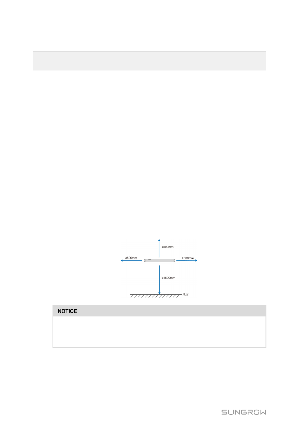
RReeqquuiirreemmeenntt ffoorr IInnssttaallllaattiioonn CClleeaarraannccee
Reserve enough clearances around the Logger3000.
Before installation, make sure the wiring terminals are at the bottom of the Logger3000
to prevent the dust or particles in the air penetrating into the device, impairing the
service life.
The installation location should be 1,500mm above the ground surface. Clearances of at
least 500mm should be reserved around the Logger3000 for ease of maintenance. The
follow figure shows the requirement for minimum clearances.
When there are external devices (such as Meteo Station) connected to the
Logger3000, users should install corresponding communication SPD according
to onsite conditions.
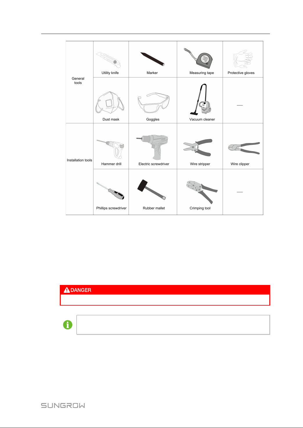
6.2 Installation Tools
Installation tools include but are not limited to the following recommended ones. If
necessary, use other auxiliary tools on site.
16
Page 23
User Manual 6 Mechanical Installation
6.3 Installing Logger3000
The Logger3000 can be installed anywhere in the room meeting the installation
environment requirements. Wall-mounted installation and rack-mounted installation are
supported.
6.3.1 Wall-Mounted Installation
Avoid drilling holes in the utility pipes and/or cables attached to back of the wall!
Turn on the vacuum cleaner and wear safety goggles and dust mask
throughout the drilling process to avoid dust inhalation or contact with eyes.
Installation component parts
• Marker (beyond the delivery scope)
• Hammer drill (beyond the delivery scope)
• Bottom supporter (in the delivery scope)
• Mounting ear (in the delivery scope)
17
Page 24
6 Mechanical Installation User Manual
• Expansion bolt (in the delivery scope)
• Tapping screw (in the delivery scope)
• Screwdriver (beyond the delivery scope)
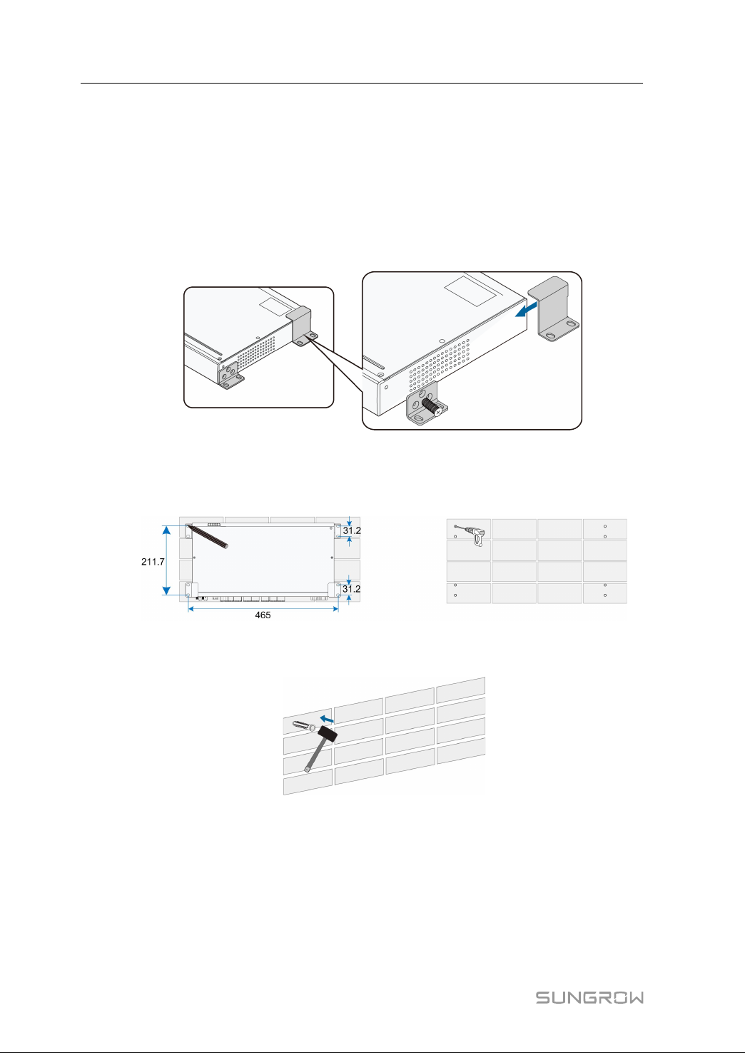
IInnssttaallll MMoouunnttiinngg EEaarrss aanndd BBoottttoomm SSuuppppoorrtteerrss
Anchor the mounting ears and bottom supporters to the Logger3000 with supplied
M4x8 cross recessed countersunk head screws. The fastening torque is 1.8-2.4N·m,
and the anchoring method is as follows:
MMoouunntt tthhee LLooggggeerr33000000 ttoo tthhee WWaallll
step 1 Mark positions for drilling holes on the installation wall. Drill the holes with a hammer drill
of φ6mm. (Note: Reserve sufficient clearances around the Logger3000.)
step 2 Insert the expansion sleeve into the drilled hole, and make it completely embedded in
the wall with a rubber hammer.
step 3 Insert the tap screw and mounting ear successively into the expansion sleeve, to fix the
Logger3000 onto the wall.
18
Page 25
User Manual 6 Mechanical Installation
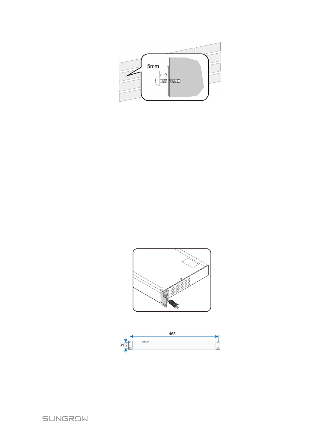
step 4 Fasten the tapping screw with a screwdriver by the torque of 0.3N·m.
-- -- EEnndd
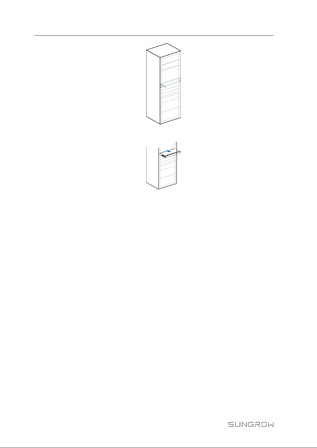
6.3.2 Rack-mounted Installation
Use 1U standard rack in case of the rack-mounted installation.
Installation tools and component parts
• 1U standard rack (beyond the scope of delivery)
• Electric screwdriver (beyond the scope of delivery)
• Screw (beyond the scope of delivery)
• Nut (beyond the scope of delivery)
IInnssttaallll mmoouunnttiinngg eeaarrss
Anchor the mounting ears to the Logger3000 with supplied M4x8 cross recessed
countersunk head screws. The fastening torque is 1.8-2.4N·m, and the anchoring
method is as follows:
step 1 Mark positions on the rack according to dimensions of the Logger3000.
step 2 Drill holes on the rack with a hammer drill of φ6mm.
19
Page 26
6 Mechanical Installation User Manual
step 3 Level the mounting ears with the drilled holes on the rack.
step 4 Fix the Logger3000 in the sequence of screws, mounting ears, rack, and nuts.
-- -- EEnndd
20
Page 27
7
Electrical Connection
7.1 Safety Instructions
High voltage hazard!
The Logger3000 should be reliably ground. Never touch the AC power supply
port "AC (10~277V)" and PLC communication port "PLC (L1、L2)" when the
device is powered on.
High voltage hazard! Danger will be caused by touching the PLC communication
port immediately after powering down. Wait at least 30s to have the capacitor
discharge completely.
Incorrect wiring will cause device damage or even personal injury.
All cables must be intact, well insulated, appropriately dimensioned, and firmly
connected.
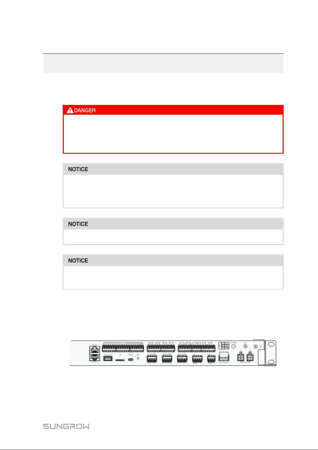
7.2 Port Introduction
External wiring terminals are located at the bottom of Logger3000, and the wiring area
is shown in the figure below.
21
Page 28

7 Electrical Connection User Manual
PPoorrtt FFuunnccttiioonn
ETH1, ETH2
DIN
USB-HOST
SD
Ethernet port
Digital input Dry contact input interface
USB port
SD port
Debug Debug port
RST Reset
DO1~DO4
PT1, PT2, AI1~AI4
A1B1~A6B6
Digital output
Analog input
RS485 communication
interface
CAN communication
CAN
port
DC24V power supply
24V
port
AC(110~277V) AC power supply port
GPS/BDS GPS antenna interface
RF
Wireless antenna
interface
DDeessccrriippttiioonn
ETH2 can be connected to the
background through devices like
switch and router.
Function of ETH1 is reserved.
Reserved
Reserved
Used for debugging of the
Logger3000
Used for hardware reset of
Logger3000
Relay output interface
Relay specification: 250Vac/1A or
30Vdc/1A
Reserved
Support of 6 inputs of RS485
Can be connected to both slave
device and background
Reserved
If the current is ≤2.0A, the switch
mode power supply at this port
requires reinforced insulation.
Connecting 110~277Vac (50/
60Hz), current≤0.5A
Used for time synchronization and
positioning
Reserved
22
PLC(L1, L2)
Grounding hole
PLC communication
interface
Connecting protective grounding
cable
Can be connected to string
inverters equipped with PLC
communication function
Page 29
User Manual 7 Electrical Connection
AACC ppoowweerr ssuuppppllyy ppoorrtt aanndd PPLLCC ccoommmmuunniiccaattiioonn iinntteerrffaaccee
High voltages may be present on the AC power supply port "AC (110~277V)" and
communication interface "PLC(L1、L2)". Therefore, before cable connection, ensure
that the two ports are free of voltage and the grounding cable is reliably connected.
DDiiggiittaall iinnppuutt//oouuttppuutt ppoorrttss
Digital input/output ports (DIN and DO1~DO4) are configured to collect node data and
control node communication.
GGPPSS wwiirreelleessss aanntteennnnaa
The wireless antenna should be installed outdoors. The GPS antenna port (GPS/BDS)
are used for time synchronization and positioning.
• The time synchronization function is available to the Logger3000 itself only.
• Positioning function can be used to read out the geographic position of the
Logger3000 with the help of communication devices.
Ensure that the Logger3000 has been powered down before installing or removing the
GPS antenna.
RRSS448855 ccoommmmuunniiccaattiioonn ppoorrttss
For the RS485 communication ports (A1B1~A6B6), the communication distance should
be no more than 1,000m.
7.3 Overview
The Logger3000 can be connected to:
• devices in the PV system such as the inverter, combiner box, Meteo Station, and
energy meter through the RS485 port
• background devices through the Ethernet port
• transformer or other devices through the PLC port
7.4 RS485 Port
7.4.1 Connecting to the Device with RS485 Port
Use an RS485 shielded twisted pair (STP) to connect any RS485 port (A1B1–A6B6) of
the Logger3000 and the RS485 communication terminal of the inverter.
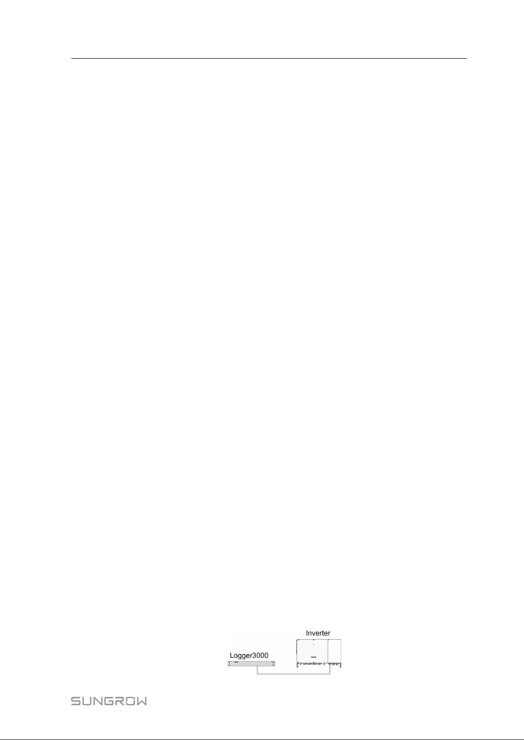
CCoonnnneeccttiinngg ttoo aa SSiinnggllee IInnvveerrtteerr
Insert the communication cable led from the inverter to any RS485 port (A1B1–A6B6)
of the Logger3000.
23
Page 30
7 Electrical Connection User Manual
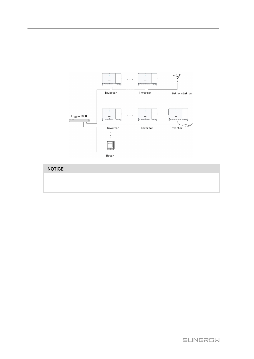
CCoonnnneeccttiinngg ttoo MMuullttiippllee IInnvveerrtteerrss
Multiple inverters are connected to the Logger3000 in the RS485 daisy chain manner. If
more than 15 inverters are connected on the RS485 bus, it is recommended to connect
a 120Ω terminal resistor in parallel on the RS485A and RS485B lines at the head or tail
end of the bus.
With an outdoor device connected to the Logger3000, it is recommended to
connect an SPD to protect the device from lightning damage.
• The Logger3000 supports 6 RS485 buses and 200 devices at most. Each RS485
bus supports 60 devices at most.
• Devices of different types must be connected to different RS485 communication
ports of the Logger3000. For example, the transformer and the inverter should be
connected to different RS485 communication ports of the Logger3000.
• The address of each device on the RS485 bus should be within the set address
range (1 to 246) of the Logger3000 without repetition. Otherwise, communication
failure occurs.
• Serial port parameters of each device on the RS485 bus should be consistent with
those of the Logger3000. The serial port parameters include baud rate, data bit, stop
bit, and check bit.
CCoonnnneeccttiioonn PPrroocceedduurree
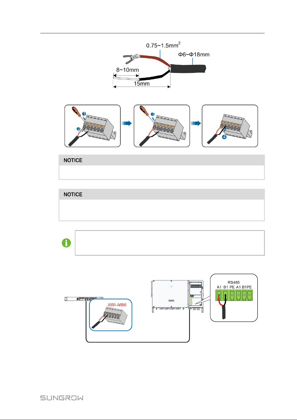
step 1 Lead the RS485 communication cable from the inverter to the wiring area of
Logger3000.
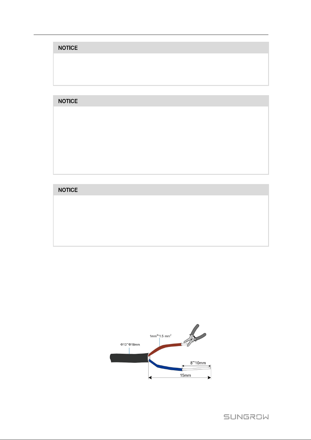
step 2 Strip the protection layer of the communication cable with a wire stripper. Cable
specification and stripped length are as follows:
24
Page 31
User Manual 7 Electrical Connection
step 3 Crimp the wiring terminal.
RS485A is connected to port A while RS485B is connected to port B.
The RS485 communication cable must be the shielded twisted pair with the
shielding layer single-point grounded.
When a multi-core multi-strand copper cable is used, crimp an appropriate
euro style terminal at the communication cable head and then connect it to
the RS485 port of the Logger3000.
step 4 Connect the wiring terminal to the terminal "A1B1~A6B6" of the Logger3000.
-- -- EEnndd
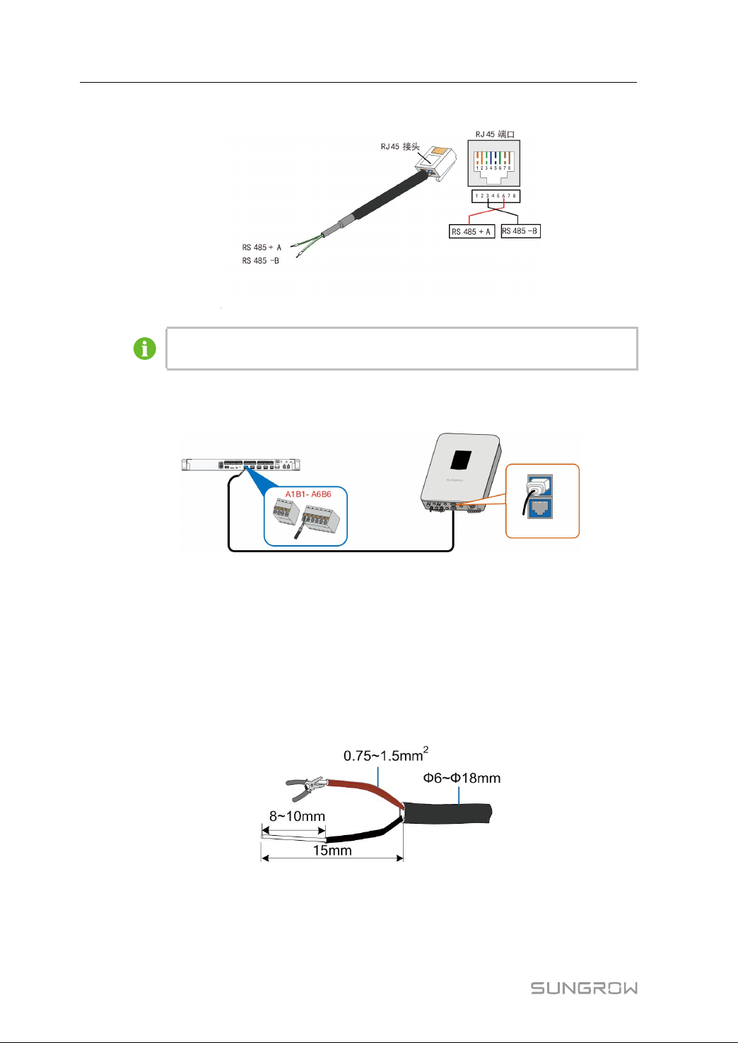
7.4.2 Connecting to the Device with RJ45 Port
step 1 Lead the RS485 communication cable from the inverter to the wiring area of
Logger3000.
25
Page 32
7 Electrical Connection User Manual
step 2 Strip the Ethernet cable.
The white-green wire 3 is defined as RS485- B wire and the green wire 6 as
RS485+ A wire.
step 3 Connect the communication cable to the RS485 port of the Logger3000, as shown in
the figure below.
-- -- EEnndd
7.4.3 Connecting to the Meteo Station
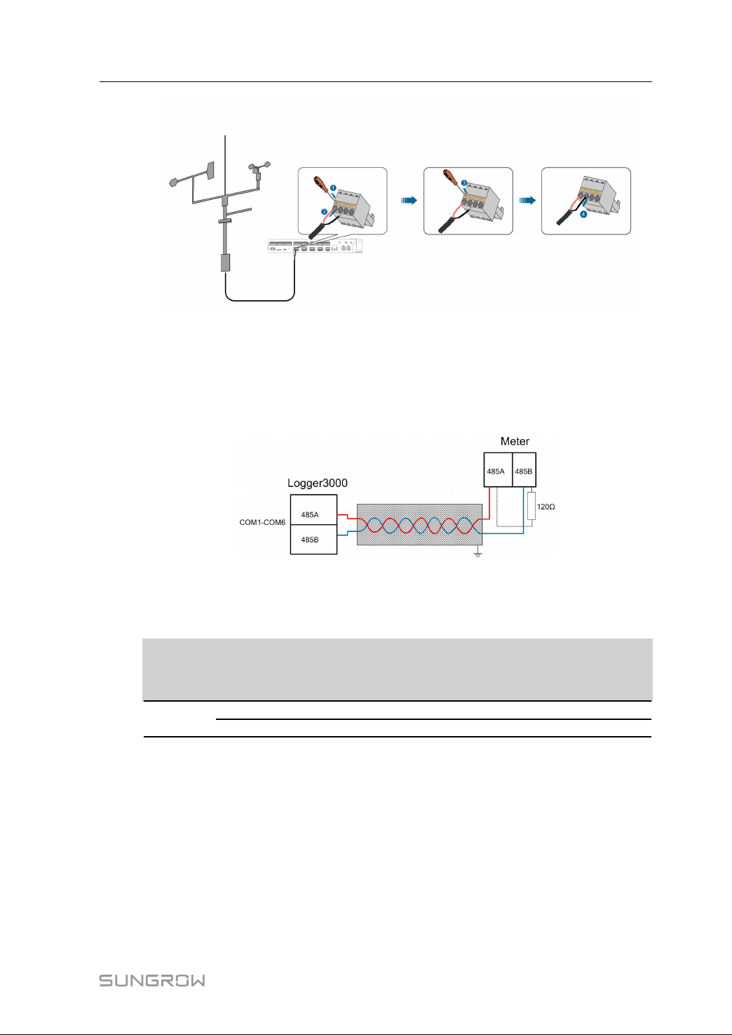
Meteo Station of the Modbus-RTU protocol can be connected to the Logger3000.
step 1 Connect the communication cable led from the Meteo Station to the RS485 port of the
Logger3000.
step 2 Strip the protection layer and insulation layer of the communication cable with a wire
striper, as shown in the figure below.
step 3 Connect the stripped cable to the RS485 port of the Logger3000, as shown in the figure
below.
26
Page 33
User Manual 7 Electrical Connection
-- -- EEnndd
7.4.4 Connecting to the Energy Meter
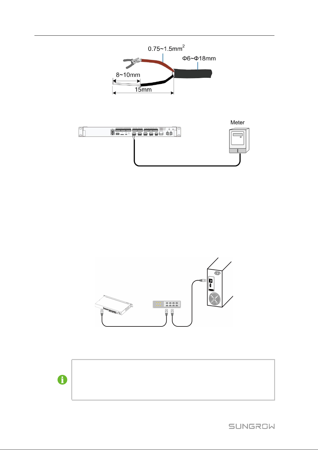
Communication connection between the Logger3000 and the energy meter is as
follows:
Energy meter can be connected to the Logger3000. The following table shows the
communication port, port definition, and protocol type of a commonly used energy
meter.
RRSS448855
BBrraanndd
ccoommmmuunniiccaattiioonn
PPoorrtt ddeeffiinniittiioonn
PPrroottooccooll ttyyppee
ppoorrtt
Acrel
21 RS485-A Modbus RTU
22 RS485-B Modbus RTU
WWiirriinngg mmeetthhoodd
step 1 Lead the RS485 cable from the energy meter to the wiring area of the Logger3000.
step 2 Strip the protection layer and insulation layer of the communication cable with a wire
striper, as shown in the figure below.
27
Page 34
7 Electrical Connection User Manual
step 3 Connect the stripped cable to the RS485 port of the Logger3000, as shown in the figure
below.
-- -- EEnndd
7.5 Ethernet Port
The Logger3000 is equipped with two Ethernet ports: ETH1 and ETH2. The function of
the ETH1 is reserved. The Logger3000 can be connected to the Ethernet switch and
router through the ETH2 port.
step 1 Insert one plug of the supplied network cable into the network port of the Ethernet
switch and the other plug into the ETH2 port of the Logger3000.
step 2 Configure network parameters.
-- -- EEnndd
• Default IP address of the ETH2 port is 192.168.1.100.
• If the ETH2 port has enabled the Dynamic Host Configuration Protocol (-
DHCP) function, the IP address of the port can be read out after the it is
connected to a router or other devices.
28
Page 35
User Manual 7 Electrical Connection
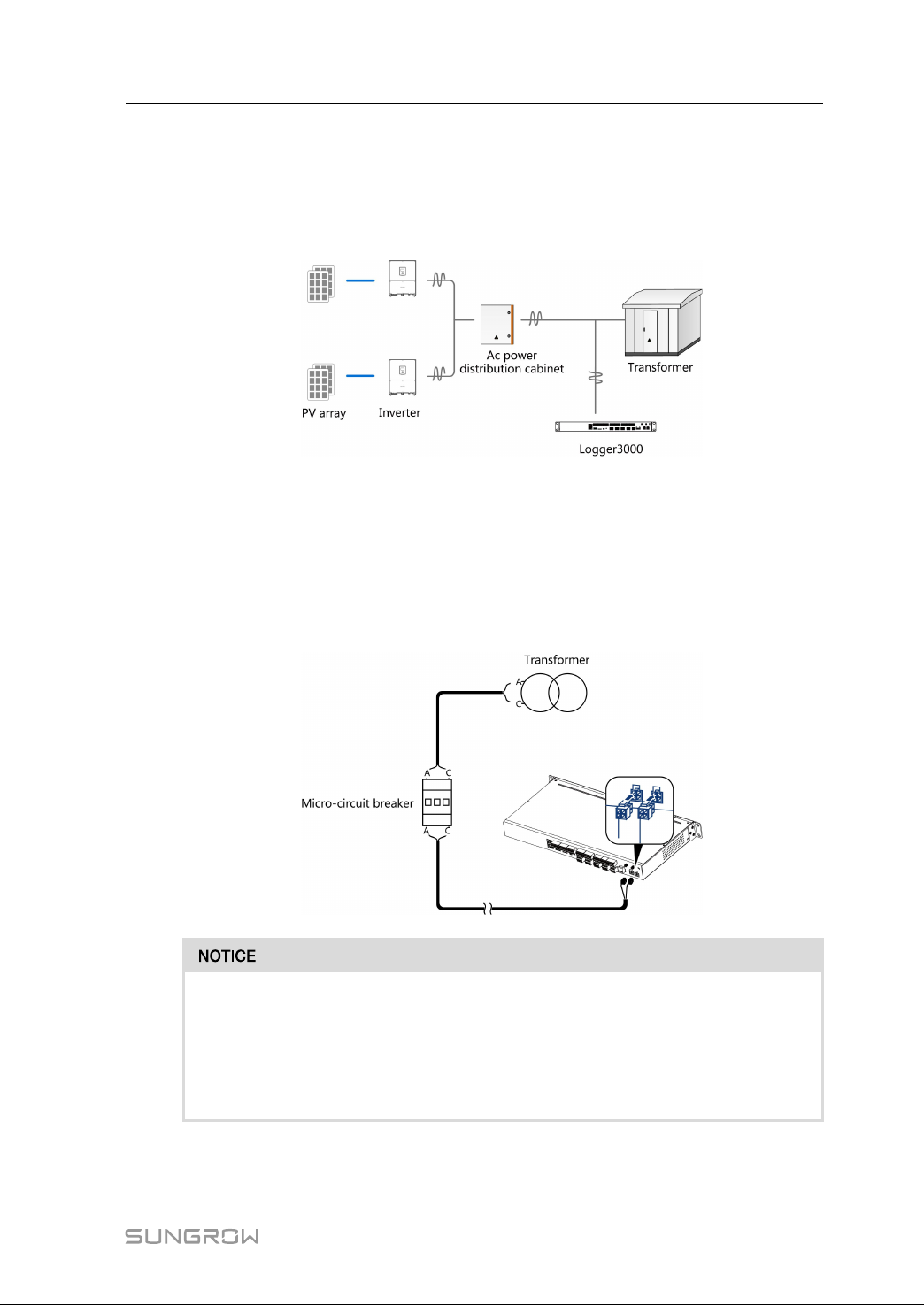
7.6 PLC Port
Integrated with PLC master node, the Logger3000 can be connected to the inverter
integrated with PLC slave node and achieve PLC communication by using existing
power cable.
PPrreeppaarraattiioonn bbeeffoorree wwiirriinngg
• Disconnect the transformer from the grid.
• Disconnect the DC side of the inverter and make sure the system is in safe state.
WWiirriinngg mmeetthhoodd
Connect one end of the supplied PLC power cable to any two phases of the micro
circuit breaker and the other end to the port "PLC(L1、L2)" of the Logger3000.
Isolation voltage of the PLC cable should be greater than 800V, recommended
cable specification: 1.5mm.
Add 800 insulation sleeve to the PLC cable.
PLC cable must be connected to an additional SPD. Otherwise, device damage
may occur.
29
Page 36
7 Electrical Connection User Manual
The built-in PLC module of the Logger3000 supports AC voltage less than 800V.
In case of PLC communication, the distance between the Logger3000 and the
inverter should be no more than 1,000m.
PLC networking is intended for medium voltage grid-connection. If low voltage
grid-connection is desired, observe the following two conditions:
• Never connect a load between the Logger3000 and the PLC slave node.
• The distance between the Logger3000 and the load should be greater than
20m, that is, the LV grid-connection point should be more than 20m away
from the nearest load distribution line. The load includes air conditioners,
machines, motors, etc.
In case of PLC communication, note that:
• Electrical connection between the inverter and its downstream transformer
has been correctly performed.
• Input and output circuit breakers of the Logger, inverter, and transformer are
connected.
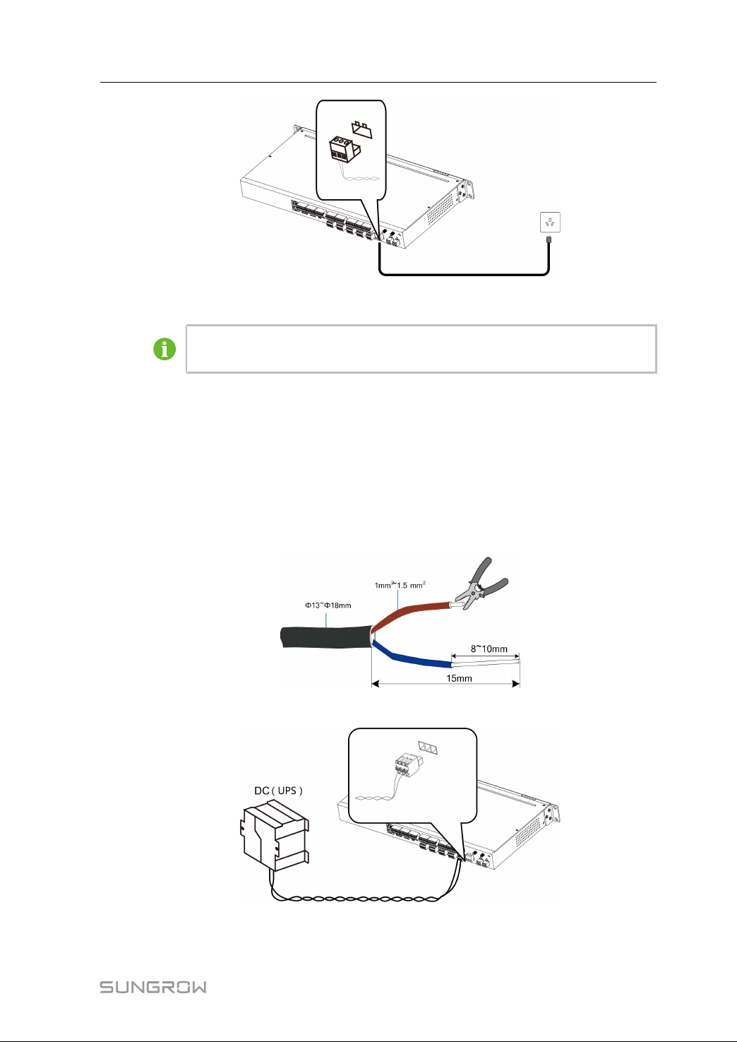
7.7 Connecting to the AC Power Supply
The Logger3000 can be connected to a power source with voltage ranging from 110 to
277Vac.
step 1 Lead the external power supply cable to the wiring area of the Logger3000.
step 2 Strip the power supply cable by an appropriate length and crimp it to an euro style
terminal.
step 3 Insert the euro style terminal to the external jack "AC110~277V" of the Logger3000.
30
Page 37
User Manual 7 Electrical Connection
-- -- EEnndd
The Logger3000 can be connected to both AC power supply and DC power
supply. UPS can be used as a DC backup power source.
7.8 Connecting to the DC Power Supply
The Logger3000 can be connected to 24Vdc external power supply. UPS can be used
as a power source.
step 1 Lead the external power supply cable to the wiring area of the Logger3000.
step 2 Strip the power supply cable by an appropriate length and crimp it to an euro style
terminal.
step 3 Insert the euro style terminal to the external jack "24V (+、-)" of the Logger3000.
-- -- EEnndd
31
Page 38
7 Electrical Connection User Manual
7.9 Earthing Connection
The grounding cable should be grounded reliably. Otherwise,
lethal electric shock may occur in case of fault; and
the device may be damaged due to lightning.
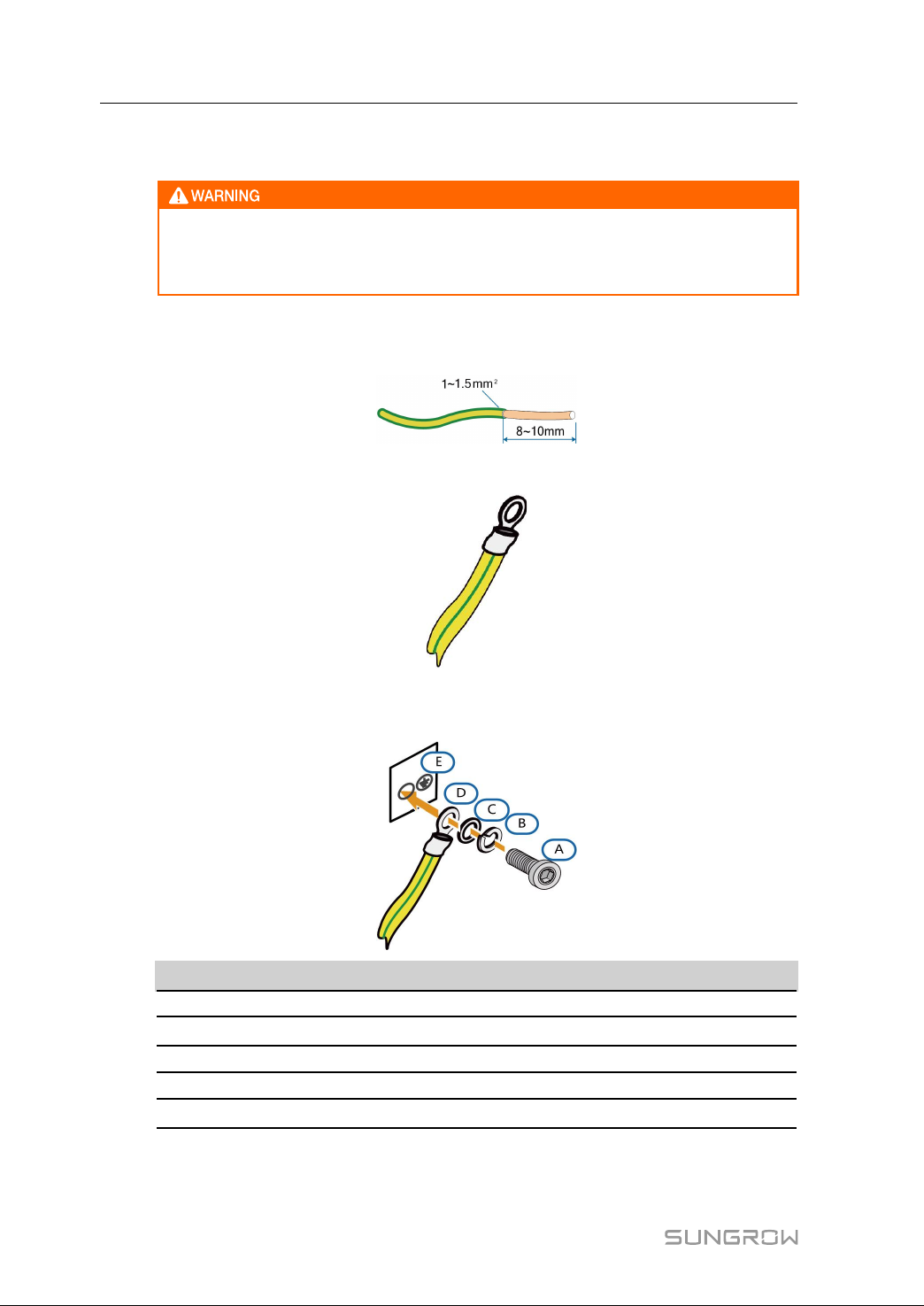
step 1 Strip the protection layer and insulation layer of the grounding cable by specific length,
as shown in the figure below.
step 2 Crimp the stripped cable into an appropriate euro style terminal.
step 3 Secure the grounding cable to the grounding hole of the Logger3000, as shown in the
figure below.
NNoo..
A Bolt M4
B
C Flat washer
D OT terminal
E
step 4 Fasten the screw with a wrench by the torque of 5±1N·m.
-- -- EEnndd
DDeessccrriippttiioonn
Spring washer
Grounding hole
NNoottee
—
—
—
—
32
Page 39

8
Commissioning
8.1 Inspection before Commissioning
NNoo.. IInnssppeeccttiioonn iitteemm
1 All cables are intact, well-insulated, and appropriately dimensioned.
2
All cables are connected correctly and firmly.
3 The polarity of the power supply cable is correct. The grounding cable is
reliably grounded.
8.2 Commissioning Steps
Commission the Logger3000 only after all the foregoing items meet requirements.
Commissioning steps are as follows:
SStteepp
NNoo..
1 Power on the Logger3000.
2 Check whether the RUN indicator of Logger3000 is normal state.
Enter the IP address, such as 192.168.1.100, of the Logger3000 in the PC
3
address bar.
4
Configure serial port parameters on the WEB interface.
Add the PV devices connected to the Logger3000 to the WEB interface by
5
means of searching or manual adding.
6
Configure IP address.
Configure the address of iSolarCloud if running data needs to be uploaded to
iSolarCloud.
If the Logger3000 is used in mainland China, it is unnecessary to configure the
7
address.
If the Logger3000 is used in regions other than mainland China, set the
address to api.isolarcloud.com.hk and the port to 19999.
Check whether running data of SUNGROW inverter is correct via the WEB
8
interface.
Check whether the forwarding data is correct via the background monitoring
9
system.
Create new plant through the iSolarCloud APP and check whether the platform
10
data is correct.
33
Page 40
9 Web Interface
9.1 Running Requirements
IItteemm PPaarraammeetteerr
System WIN7, WIN8, WIN10
Browser
Min. resolution 1366 x 768
CPU CPU frequency higher than 2.5GHz
9.2 Preparation before Login
• Connect the PC to the ETH2 port of the Logger3000, and the IP address of the ETH
port is 192.168.1.100 by default.
• Set the PC IP address to a value within the same network segment as that of the IP
address of the port ETH2. For example, the PC IP address can be set to
192.168.1.125 and the subnet mask to 255.255.255.0.
9.3 Login Steps
IE10 - IE11, Chrome43 - Chrome45
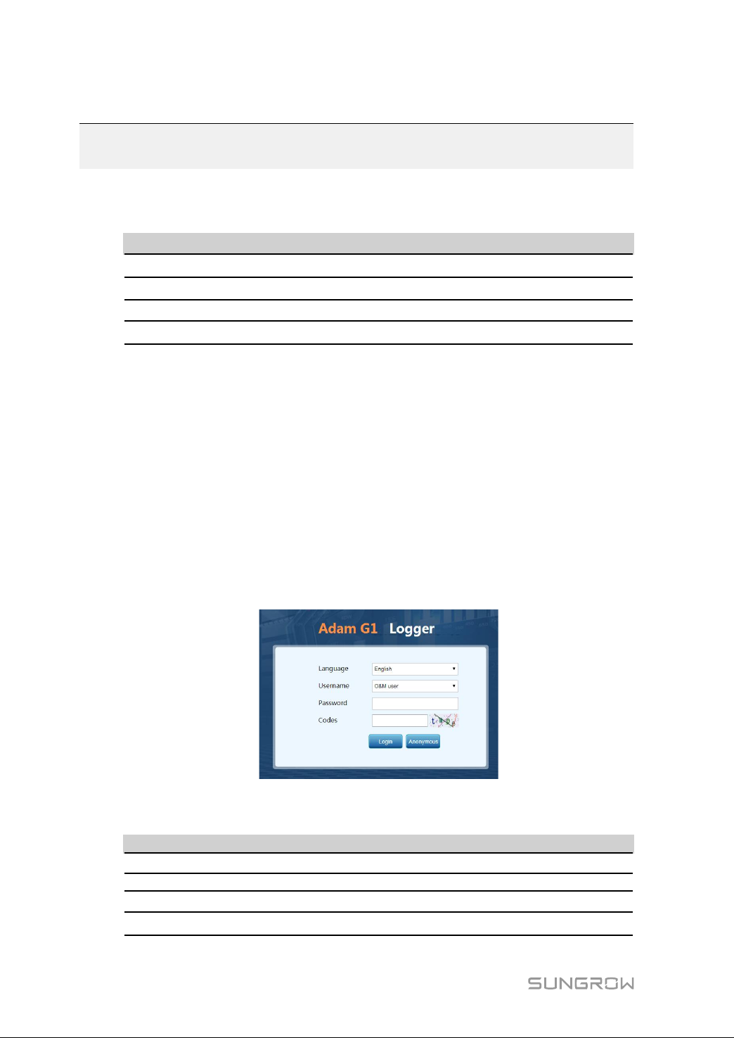
step 1 Enter the IP address, for example, 192.168.1.100, of the port ETH2 in the address bar
of the PC, to enter the login interface, as shown in the figure below.
step 2 Select the desired language and user role (for example, O&M user), enter the default
password "adamg1", fill in the verification code, and click "Login".
RRoollee PPaasssswwoorrdd
O & M user
R & D user Unavailable
Factory user
Anonymous
adamg1
Unavailable
Log in without a password
34
Page 41
User Manual 9 Web Interface
-- -- EEnndd
9.4 Web Interface
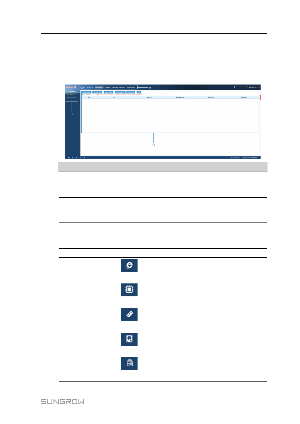
The WEB interface is as follows:
NNoo.. NNaammee
st
1
A
navigation
menu
st
2
B
navigation
menu
Function
C
display
area
D User
E Info icon
DDeessccrriippttiioonn
Display the main function modules of WEB
st
After selecting the 1
corresponding info through the 2
function module, check or set the
nd
navigation menu
Display the present selected check or set function interface
Display the present login user
Internet access
CPU use rate
memory use rate
hardware use rate
total number of online devices
35
Page 42
9 Web Interface User Manual
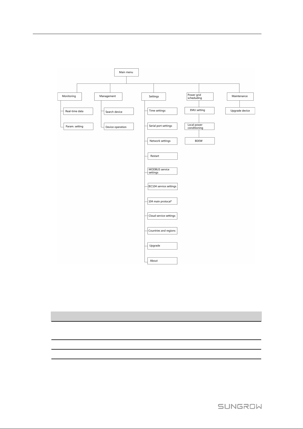
9.5 Web Menus
The following figure shows the menus of the O&M user.
Note: * is optional.
9.6 Operation Flow
Operate as follows to log into the Logger3000 for the first time.
SStteepp RReeffeerreennccee cchhaapptteerr
1. Check that external devices are
correctly connected to the Logger3000.
2. Set the serial port of the Logger3000.
3.*Automatically search device.
36
"7 Electrical Connection"
"9.9.2 Serial Port Setting"
"9.8.1 Searching Device"
Page 43
User Manual 9 Web Interface
SStteepp RReeffeerreennccee cchhaapptteerr
4. Add device.
5.Perform the service settings.
Note: For devices that support automatic search function (like SUNGROW string
inverters), you can search the devices and allocate the address automatically.
"9.8.2 Device Operation"
"9.9.5 Modbus Service"
"9.9.6 IEC104 Service Settings"
"9.9.7 IEC104 Main Protocol Settings
(Optional)"
9.7 Monitoring
On the "Monitoring" interface, users can perform the following operations:
• View information such as the real-time data of devices (for example, inverter)
connected to the Logger3000.
• Set parameters of devices managed by the Logger3000, including initial parameters,
running parameters, protection parameters, and system parameters.
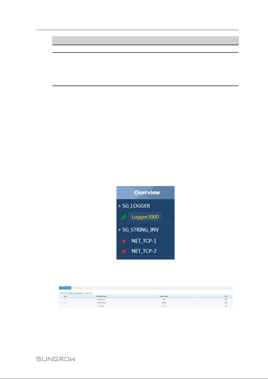
The left sidebar "Overview" displays a list of devices currently managed by the
Logger3000.
9.7.1 View Real-Time Data
Click "Monitoring" -> "Real-time data" to enter the corresponding interface.
Select a device, for example, an inverter, from the sidebar "Overview" to view real-time
data of the corresponding device.
Click "DC data" and "Device attributes" on this interface to view corresponding
information.
Tick the checkbox "Auto refresh" so that the system will refresh data once every 10s.
37
Page 44
9 Web Interface User Manual
9.7.2 Single-Parameter Setting
step 1 Select a device from the left sidebar "Overview".
step 2 Tick a to-be-set parameter and enter the setting value.
step 3 Click "Setting."
-- -- EEnndd
9.7.3 Batch Setting
step 1 Select a device from the left sidebar "Overview".
step 2 Tick multiple to-be-set parameters and enter the setting values.
step 3 Click "Batch setting".
-- -- EEnndd
9.7.4 Parameter Readback
The function is used to read out set parameter values of the current device.
step 1 Select a to-be-read back device from the left sidebar "Overview".
step 2 Tick a to-be-read back parameter.
step 3 Click "Query" to read out the parameter value of the device.
-- -- EEnndd
If parameter values fall beyond the set range or the device does not support
the readback function, the set values will be in red.
9.7.5 Checking the Parameter Setting Log
The function is used to view parameter setting logs of a device. The method is as
follows:
step 1 Click the icon
interface.
step 2 Select a device name.
step 3 Click "Search".
-- -- EEnndd
in the upper right corner on the "Monitoring" -> "Param. setting"
9.8 Device Management
The "Management" menu is used to manage devices connected to the Logger3000
and configure addresses for them.
38
Page 45
User Manual 9 Web Interface
9.8.1 Searching Device
The function is used to search for devices equipped with searching function, such as
string inverter, and allocate address to them.
Devices can be searched for in the following two manners:
• Searching by Port
• Searching by Address
9.8.1.1 Searching by Port
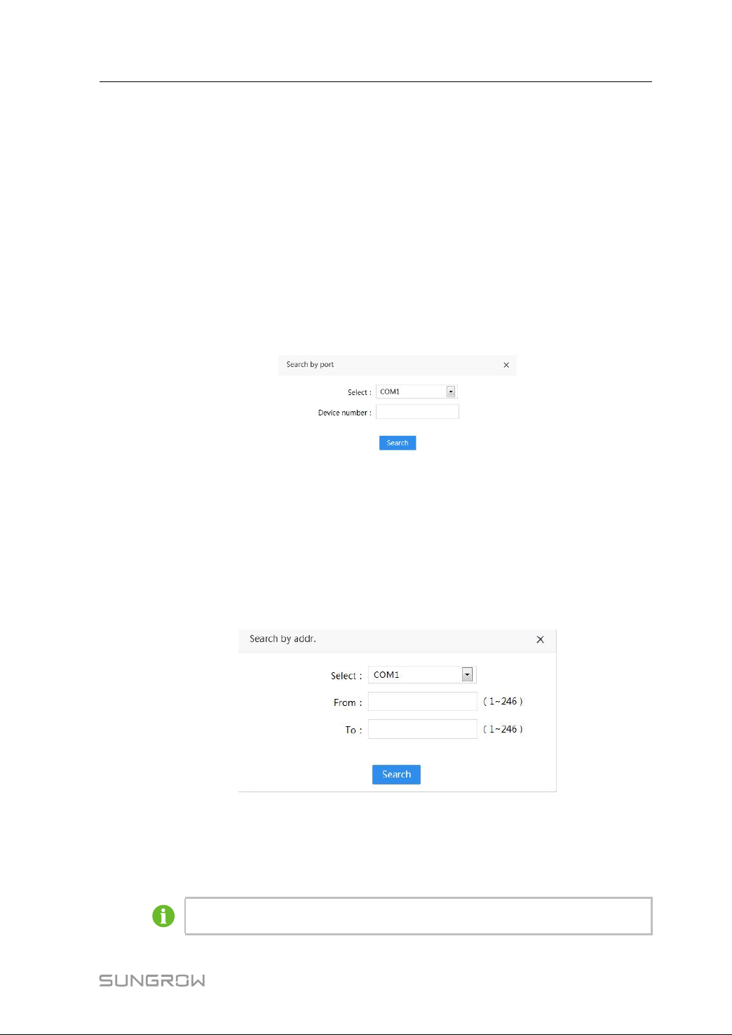
step 1 Click "Management" -> "Search device" to enter the corresponding interface.
step 2 Click "Search by port", select a serial port name, enter the device number, and click
"Search".
step 3 Click "Save" after the searching operation ends.
-- -- EEnndd
9.8.1.2 Searching by Address
step 1 Click "Management" -> "Search device" to enter the corresponding interface.
step 2 Click "Search by addr.", select a serial port name, enter the start address and end
address, and click "Search".
step 3 Click "Save" after the searching operation ends.
Corresponding device information can be viewed after the searching operation ends.
-- -- EEnndd
There should be no repeated addresses. Otherwise, the searching shall fail.
39
Page 46
9 Web Interface User Manual
9.8.1.3 View Searched Devices
View the searched devices in the following three manners on the "Search device"
interface.
FFuunnccttiioonn bbuuttttoonn
DDeevviiccee
Display devices All devices searched
Search by port
Search by addr.
Devices searched by port
Devices searched by address range
9.8.1.4 Export Results
After the searching operation ends, click "Export results" on the "Search device"
interface, to export the searched devices in the report form.
9.8.1.5 Reallocate Address
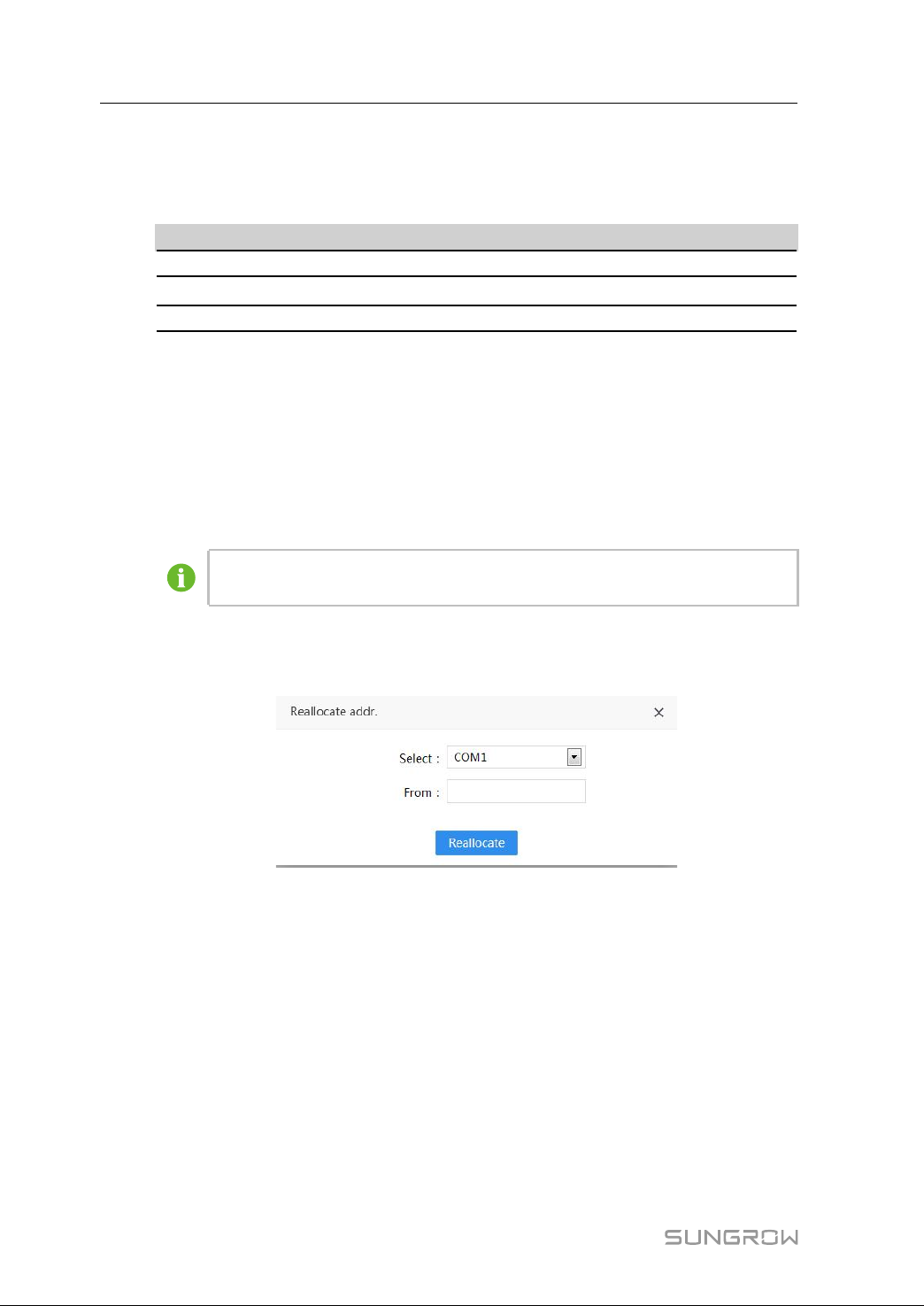
This function is used to allocate address to devices searched.
In this case, the devices should support the automatic address allocation
function.
step 1 Click "Reallocate addr." on the "Search device" interface.
step 2 Select a serial port, enter start address and end address, and click "Allocate".
step 3 Click "Save".
-- -- EEnndd
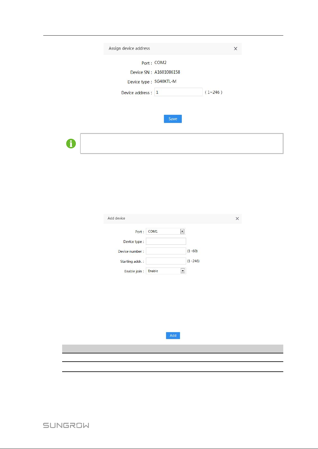
9.8.1.6 Modify the Device Address
After the searching operation ends, a list of devices searched will be displayed on the "-
Search device" interface.
On this interface, click "Reallocate addr." to enter the device address manually, and click
"Save" to finish the setting.
40
Page 47
User Manual 9 Web Interface
Never modify the device address arbitrarily. Make sure the new address is not
repeated and consistent with the actual device address.
9.8.2 Device Operation
This function is used to add, modify, and delete devices connected to the Logger3000.
AAdddd DDeevviiccee
Click "Add device" on the "Device operation" interface, and fill in the required
information on the pop-up window.
PPaarraammeetteerr
Port
Device type
Device number
DDeessccrriippttiioonn
Includes COM1~COM6, PLC, NET_TCP, and NET_IEC104
Select the corresponding type of the device
The max. value is 5 when the port parameter is set to "NET_
TCP" or "NET_IEC104"
It can only be set to 1 when the port parameter is set to "NET_
IEC104"
41
Page 48
9 Web Interface User Manual
PPaarraammeetteerr
DDeessccrriippttiioonn
Starting address Range: 1~246
Enable join Can be set to "Enable" or "Disable" according to requirements
After filling in the information, click "Add" to save the operations.
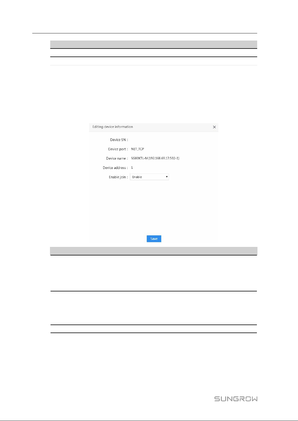
EEddiittiinngg DDeevviiccee IInnffoorrmmaattiioonn
This function is used to modify names and addresses of devices connected to the
Logger3000. The method is as follows:
Click "Edit" on the "Device operation" interface, and then "Save" to save the editing
operation.
42
PPaarraammeetteerr
DDeessccrriippttiioonn
Named in the format of device type-(port number-port
address)
Device name
PLC communication port: C
COM (A1B1~A6B6) communication ports: 1, 2, 3, 4, 5, and 6
Range: 1~246
Device address
Never modify the device address arbitrarily. Make sure the
new address is not repeated and consistent with the actual
device address.
Enable join
Enable/Disable
DDeelleettiinngg DDeevviiccee
If a device has been removed on site, it should be deleted from the Web interface. The
method is as follows:
Select the device to be deleted, click "Delete" on the operation bar, and click "Save" to
save the operation.
Page 49
User Manual 9 Web Interface
9.8.3 Firmware Upgrade
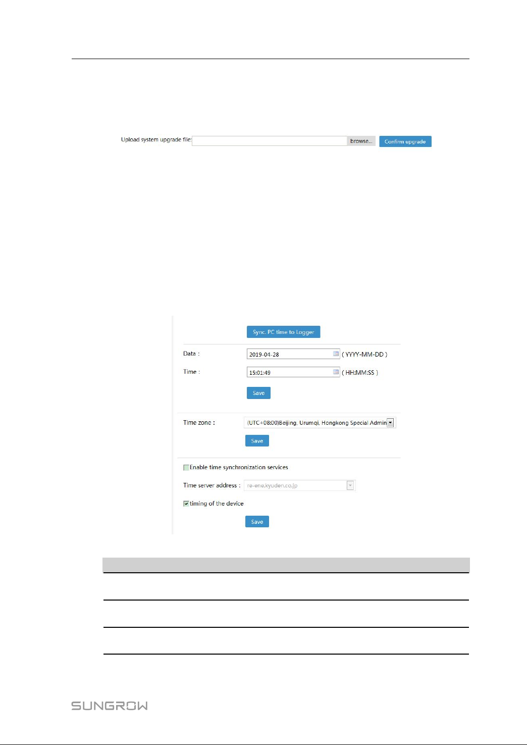
This function is used to upgrade the firmware of the Logger3000.
Method: Click "Setting" -> "Upgrade" to enter the corresponding interface.
Click "browse" to import an upgrading file, and then click "Confirm upgrade".
9.9 System Setting
9.9.1 SystemTime Setting
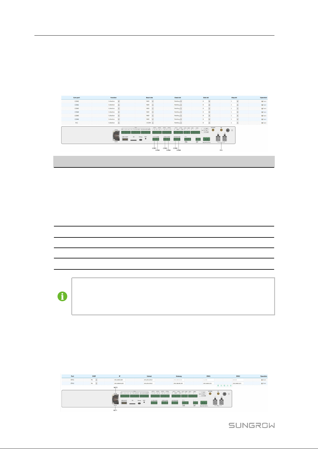
This function is used to set the system time and time zone of the Logger3000. The
method is as follows:
step 1 Click "Settings" -> "Time setting" to enter the corresponding interface.
step 2 Fill in the required information on the interface.
Time setting method is as follows:
PPaarraammeetteerr DDeessccrriippttiioonn
Sync. PC time to
Logger
Date
Time
-- -- EEnndd
Click this button to synchronize the time of Logger3000 and PC.
System date of the Logger3000 is in the format of "YYYY-MMDD", that is, year-month-day.
System time of the Logger3000 is in the format of "HH:MM:SS",
that is, hour-minute-second.
43
Page 50
9 Web Interface User Manual
9.9.2 Serial Port Setting
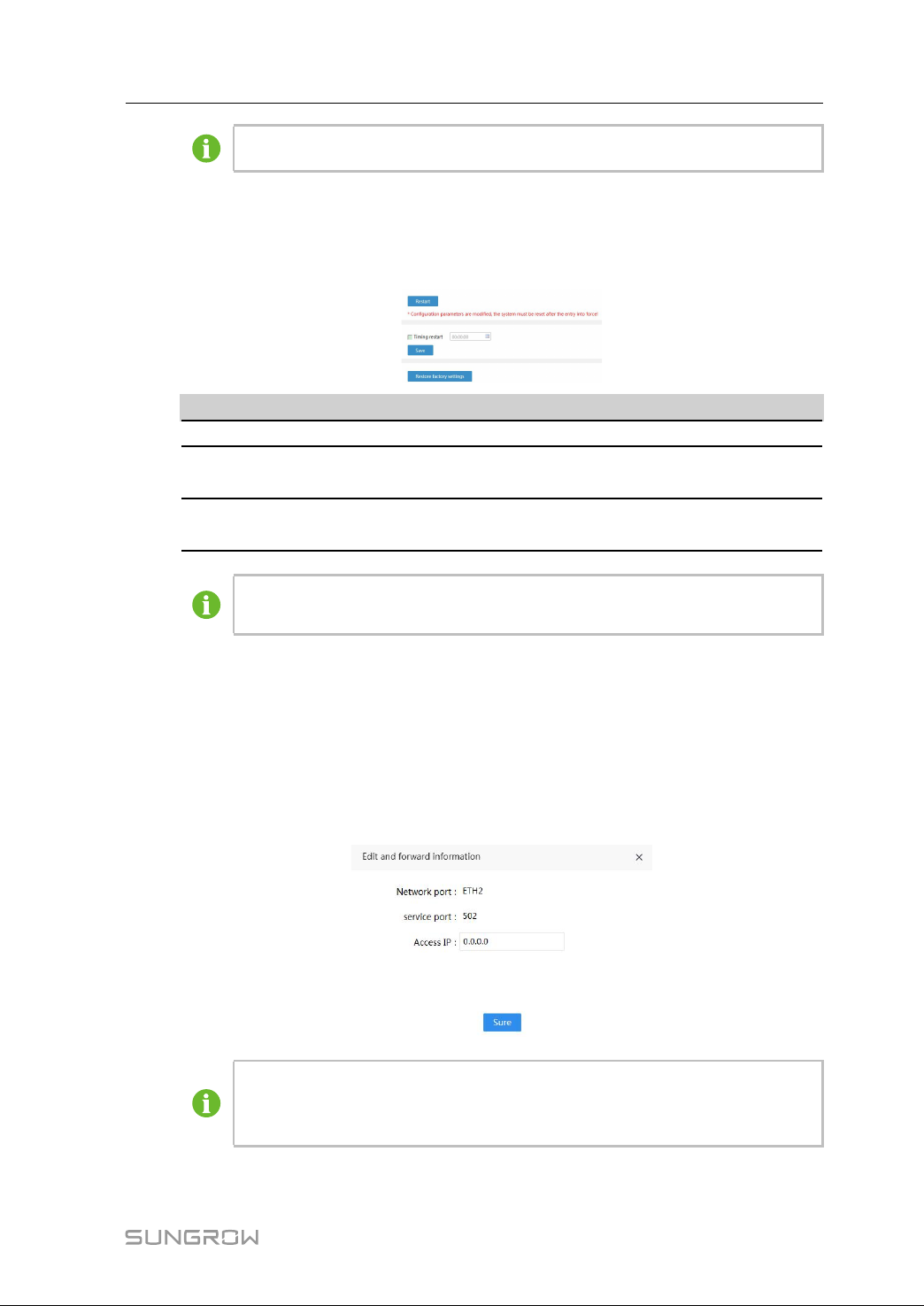
This function is used to set serial port parameters of the Logger3000, such as PLC port
and COM port (A1B1~A6B6). The parameters include function, baud rate, check bit,
stop bit, etc.
Click "Settings" -> "Serial port settings" to enter the corresponding interface.
PPaarraammeetteerr
Function
Baud rate
Check bit Default value: Null
Data bit Default value: 8
Stop bit
When a device is connected to the serial port of the Logger3000, make sure
the "bud rate", "check bit", "data bit" and "stop bit" of the serial port are
consistent with the configuration of the device, to ensure normal
communication.
9.9.3 Network Setting
DDeessccrriippttiioonn
Includes collection and forwarding background
When a device is connected to the serial port of the Logger3000, set
the function to "Collection".
There should be no more than 3 serial ports whose "function" is set to
"Forwarding background". It is recommended to use COM4/COM5/
COM6 as the forwarding serial port.
Default value: 9600bps
Default value: 1
44
This function is used to configure network parameters of the Logger3000. The method
is as follows:
Click "Settings" -> "Network settings" to enter the corresponding interface. After
performing the operation, click "Save" in the right operation bar.
Page 51
User Manual 9 Web Interface
Default IP address of the ETH2 is 192.168.1.100.
9.9.4 Restarting
This function is used to restore factory settings or restart the Logger3000.
Click "Settings" -> "Restart" to enter the corresponding interface.
OOppeerraattiioonn
Restart Performed to restart the Logger3000.
Timing restart
Restore factory
settings
The modification of parameters (serial port parameters, network parameters,
and service configuration) will not be valid before the system is restarted.
9.9.5 Modbus Service
This function is used to configure the Modbus service of the Logger3000. The method is
as follows:
Click "Settings" -> "Modbus services" to enter the corresponding interface.
• Click "Forwarding service cfg." to view the configuration information.
• Click "Network port" to set network port parameters.
DDeessccrriippttiioonn
Tick "Timing restart", select the time, and click "Save", so that
the Logger3000 will be restarted at the set time.
Click "Restore factory settings" to clear all information except
for IP address of the Logger3000.
If the access IP is set to "0.0.0.0", any background device with valid IP address
can access the Logger3000. If the access IP is set to a specific value, only this
background can access the Logger3000.
45
Page 52
9 Web Interface User Manual
9.9.6 IEC104 Service Settings
This function is used to configure the IEC104 services of the Logger3000. The method
is as follows:
Click "Settings" -> "IEC104 service settings" to enter the corresponding interface.
If the access IP is set to "0.0.0.0", any background device with valid IP address
can access the Logger3000.
If the access IP is set to a specific value, only this background can access the
Logger3000.
9.9.7 IEC104 Main Protocol Settings (Optional)
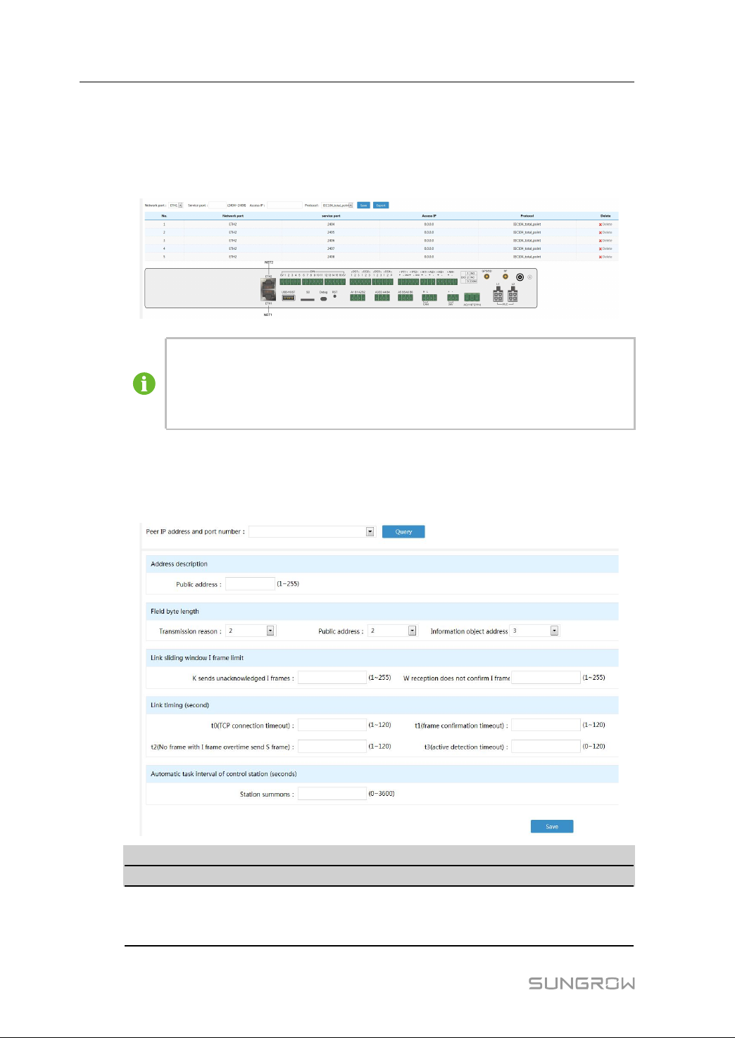
If a device whose type is NET_IEC104 has been added on the "Management" -> "Device operation" interface, perform this setting accordingly.
PPaarraammeetteerr DDeessccrriippttiioonn RRaannggee
AAddddrreessss ddeessccrriippttiioonn
Public address Address of different
1~255
slave stations on the
IEC104 link
46
Page 53

User Manual 9 Web Interface
PPaarraammeetteerr DDeessccrriippttiioonn RRaannggee
FFiieelldd bbyyttee lleennggtthh
Transmission reason
Byte length of the
1, 2
transmission reason
Public address
Information object
-
-
1, 2
1, 2, 3
address
LLiinnkk sslliiddiinngg wwiinnddooww II ffrraammee lliimmiitt
K sends
unacknowledged I
frames
When the number of
frames unacknowledged
by the slave station
1~255
reaches K, the master
station stops sending
data and wait the slave
station to acknowledge
them.
W reception does not
confirm I frames:
When the number of
frames unacknowledged
1~255
by the master station
reaches W, the master
station actively sends
acknowledgement
frames.
LLiinnkk ttiimmiinngg ((sseeccoonndd))
t0(TCP connection
timeout)
t1(frame
confirmation timeout)
TCP connection timeout
time
Frame
acknowledgement
1~120
1~120
timeout tim
t2(No frame with I
frame overtime send
S frame)
t3(active detection
timeout)
Timeout time for sending
the S frame by the non-
piggy frame I
Active detection timeout
time
1~120
0~120
AAuuttoommaattiicc ttaasskk iinntteerrvvaall ooff ccoonnttrrooll ssttaattiioonn ((sseeccoonnddss))
Station summons Station summon period
0~3600
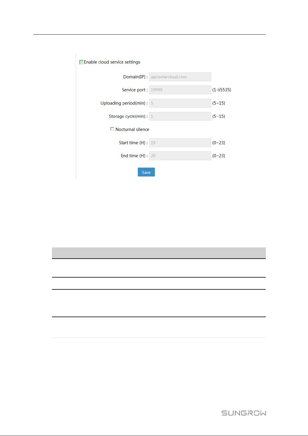
9.9.8 Cloud Service Setting
On this interface, users can set parameters related to iSolarCloud service, including
whether to enable cloud service settings, corresponding domain, service port, uploading
period, storage cycle, etc., and whether to enable the silence function, the start time an
end time. The method is as follows:
47
Page 54
9 Web Interface User Manual
Click "Settings" -> "Cloud service settings" to enter the corresponding interface.
CClloouudd sseerrvviiccee sseettttiinngg
Enable the cloud service setting function if you want to upload the device information
collected by the Logger3000 to the iSolarCloud. Otherwise, you may enable or disable
the function.
The method is as follows:
Tick the option "Enable cloud service settings" on the "Cloud service settings" interface,
and set corresponding parameters.
48
PPaarraammeetteerr
Domain (IP)
Service port
Uploading period
(min)
DDeessccrriippttiioonn RRaannggee
Domain of iSolarCloud: api.
isolarcloud.com
-
-
1-65535
Period of data transmission
between the Logger3000 and
5~15
iSolarCloud
Storage cycle
(min)
-
5~15
NNooccttuurrnnaall ssiilleennccee ffuunnccttiioonn aanndd ppaarraammeetteerr sseettttiinngg
If the "Nocturnal silence" function is enabled, there will be no data exchange between
the Logger3000 and iSolarCloud during the set time.
Generally, the time segment can be set to 0~23h. specifically, you may set the start time
and end time according to needs.
Page 55
User Manual 9 Web Interface
9.9.9 Country and Region Setting
According to the requirements of the grid company, the working status of the inverter
forwarded by the Logger3000 must be uploaded to the local background according to
the local standards.
Therefore, set the country and region to the location where the Logger3000 is installed
before using it.
The method is as follows:
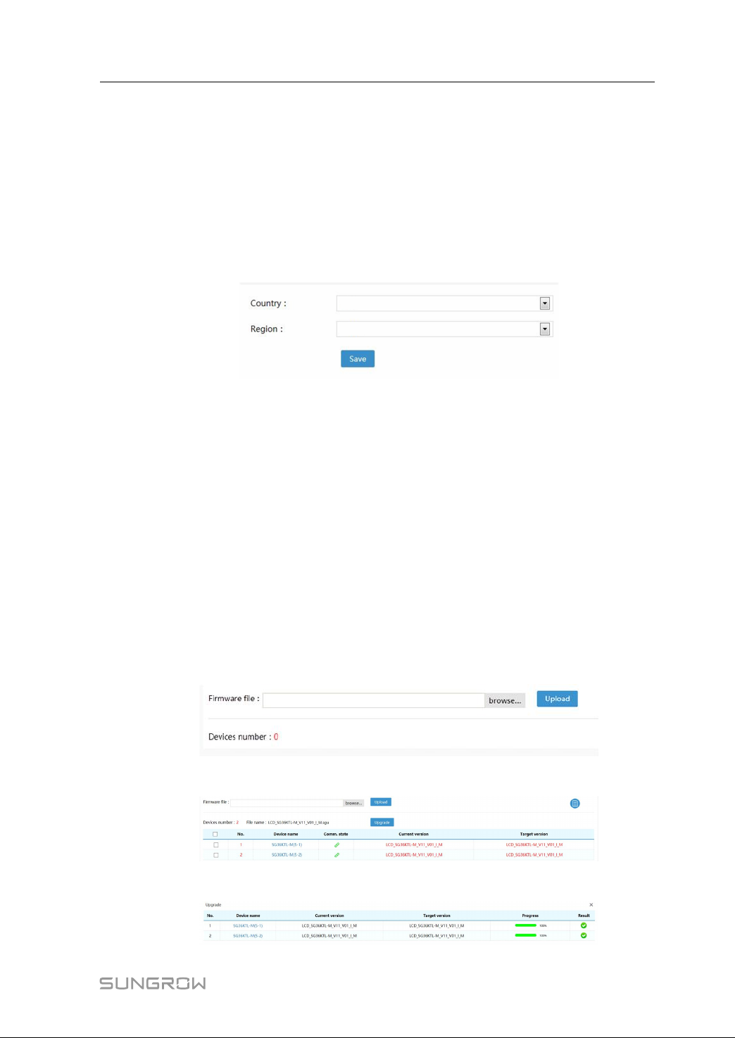
Click "Settings" -> "Countries and regions" to enter the corresponding interface.
For different regions, the codes of inverter working status forwarded by the Logger3000
are shown in the table below.
9.9.10 About
This interface includes information such as the name of the Logger3000, serial number,
password, firmware version, and web version.
Click "Settings" -> "About" to enter the corresponding interface and view related
information.
9.10 Maintenance
On this interface, user can upgrade devices managed by the Logger3000.
The method is as follows:
step 1 Click "Maintenance" -> "Upgrade device" to enter the corresponding interface.
step 2 Click "browse" to select an upgrade file, and click "Upload" to upload the desired file.
step 3 Select devices to be upgraded.
49
Page 56

9 Web Interface User Manual
-- -- EEnndd
50
Page 57
10
Grid Dispatching
10.1 Function Description
The Logger3000 includes a power control module inside used to receive control
instruction from the grid dispatching center and send the control instruction to the
monitored inverters through the RS485 port, thereby controlling the output active power,
reactive power, power factor, and start or stop of the inverter.
10.2 Grid Dispatching Plans
The grid dispatching plans include direct-connection networking and cascading
networking.
DDiirreecctt--ccoonnnneeccttiioonn NNeettwwoorrkkiinngg
In the direction-connection mode, all inverters of the current power plant are connected
to one Logger3000. In this mode, the Logger3000 has the following two functions:
• EMU (energy management) function
The Logger3000 can compare data of the gateway meter with the real-time power
of the inverter, thereby dynamically adjusting the active power or reactive power of
the inverter. For more information. refer to "10.3 EMU Setting"。
• Data upload function
The Logger3000 can upload the running data of the inverter in the PV system to
iSolarCloud.
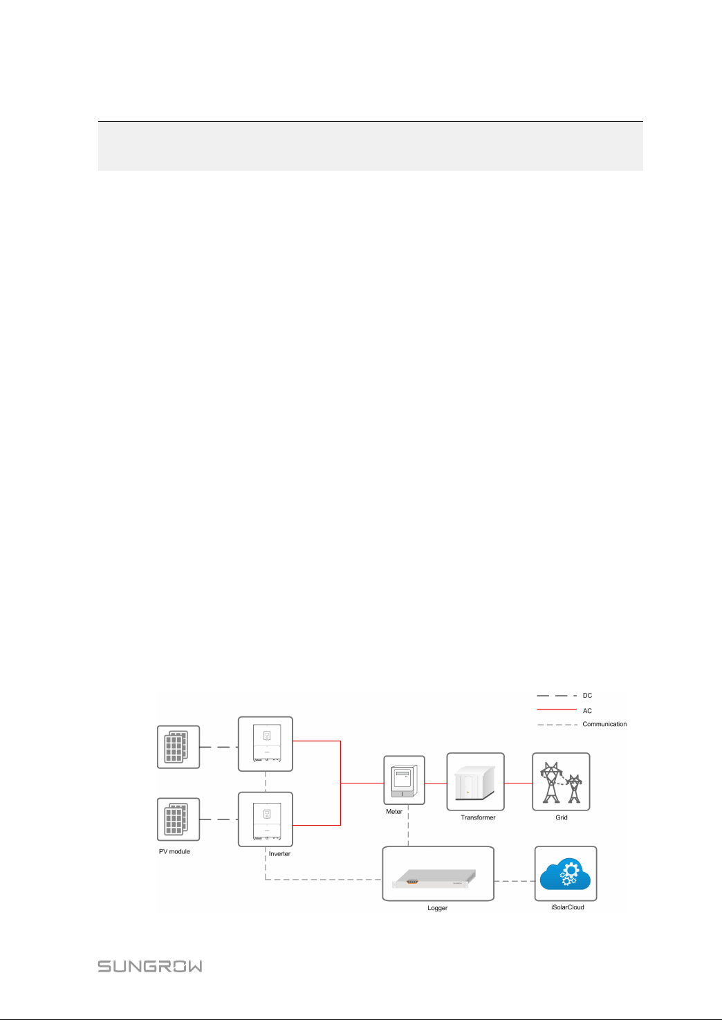
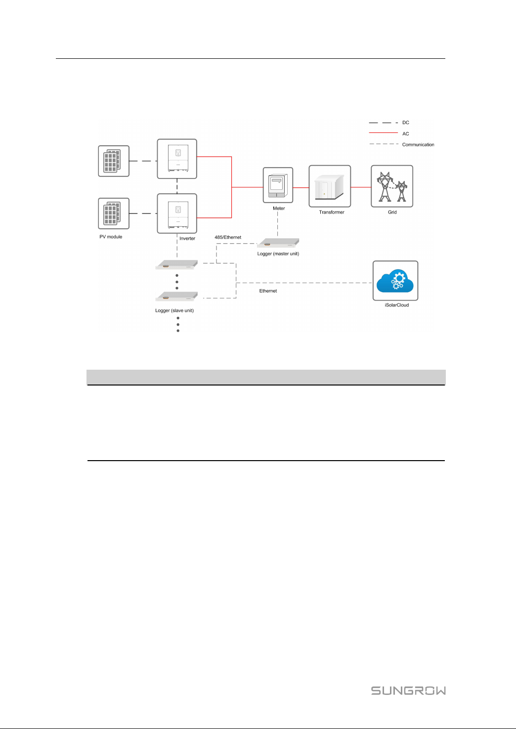
The schematic diagram of the direct-connection networking is as follows:
51
Page 58
10 Grid Dispatching User Manual
CCaassccaaddiinngg NNeettwwoorrkkiinngg
In the cascading mode, inverters can be connected to multiple Loggers. The schematic
diagram is as follows:
The Logger3000 connected to the inverter is slave unit by default; and the Logger3000
connected to the meter and the slave unit is master unit by default.
MMaasstteerr uunniitt ffuunnccttiioonn SSllaavvee uunniitt ffuunnccttiioonn
Data upload function
• Directly upload running data of the inverter to
EMU function
The function needs to be enabled manually. For specific method, refer to "10.3 EMU
Setting"
iSolarCloud.
• Upload running data of the slave unit to the master unit
and receive control instruction from the master unit.
10.3 EMU Setting
This function is applicable to China & APAC and Japan only.
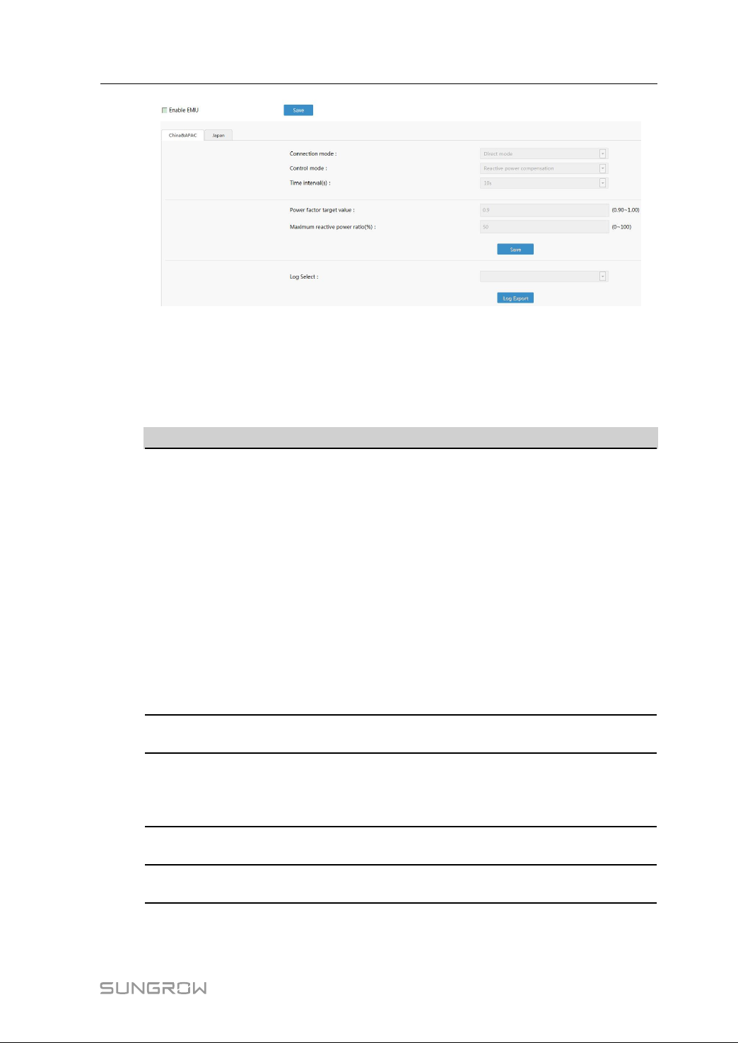
step 1 Click "Power grid scheduling" -> "EMU setting" to enter the corresponding interface.
52
Page 59
User Manual 10 Grid Dispatching
step 2 Select the corresponding country/region.
step 3 Tick the option "Enable EMU".
step 4 Set related parameters.
For China & APAC, description of the settable parameter are as follows:
PPaarraammeetteerr
Connection
mode
Control
mode
Maximum
reactive
power ratio
(%)
Power factor
target value
Time interval
(s)
DDeessccrriippttiioonn
It can be set to direct mode or cascading host mode.
Set the connection mode according to actual networking scheme.
• In case of direct-connection networking, set the connection mode
to "Direct mode", and then click "Management" -> "Device
operation" to add inverter and meter connected to the Logger3000.
• In case of cascading networking, set the connection mode to "Cascading host mode", and then click "Management" -> "Device
operation" to add slave units and meter connected to the master
unit. The salve units and meter should support Modbus TCP
protocol, and the address of the slave unit can only be set to 247.
A maximum of 5 inputs of connections are supported.
Note: For the cascading mode, only the EMU function of the master
unit can be enabled. Never enable the EMU function of the slave unit.
It can be set to reactive power compensation or active control
according to needs.
When the "control mode" is set to "Reactive power compensation",
the parameter needs to be configured.
When the "control mode" is set to "Reactive power compensation",
the parameter needs to be configured.
It can be set to 10s, 20s, or 30s; and it is 10s by default.
For Japan, description of the settable parameter are as follows:
53
Page 60
10 Grid Dispatching User Manual
PPaarraammeetteerr DDeessccrriippttiioonn
Remote
scheduling
Local
scheduling
Time
modification
Tick the option "Enable EMU", enable the "Remote scheduling"
function, fill in related information, import the scheduling file, and
click "Save", to enable the remote scheduling function.
Tick the option "Enable EMU", select the "Local scheduling" function,
import the scheduling file, set the parameter type, and click "Save",
to enable the local scheduling function.
Perform modification according to actual conditions. The parameter
ranges from -10 to +10. After the modification saved, the option "Time settings" -> "Sync. PC time to Logger" will not be displayed.
When the system time of the Logger3000 < the time modified
through "Time modification", or the time of the Logger3000 < NTP
time,
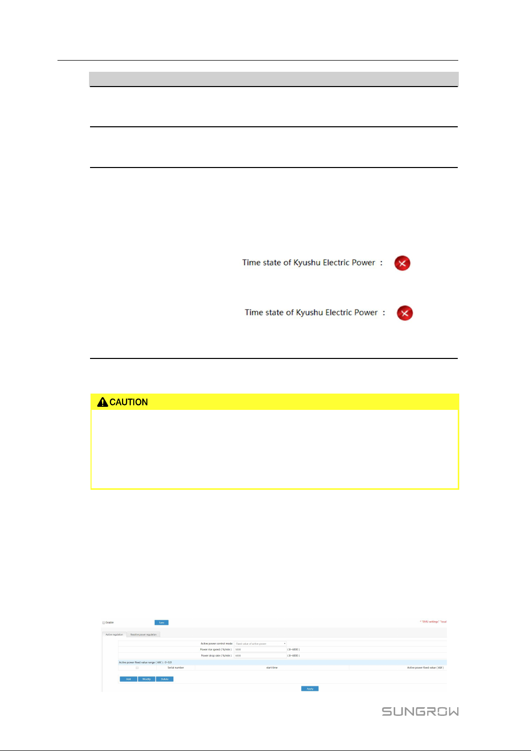
the information ”
appear on in the upper right corner of the interface. In this case, the
Logger3000 sends stop instruction to the inverter.
The information ” ” will
not disappear until operation such as "Time modification" or NTP
synchronization is performed.
-- -- EEnndd
After saving the operations, enter the permission password Sglogger2018 to
have the settings valid.
If an error schedule is imported due to human reasons, causing abnormal
sending of control instructions, SUNGROW shall not be held liable for any
damage caused.
10.4 Local Power Regulation
The Logger3000 can regulate the power of inverter connected to it. The regulation
includes active power regulation and reactive power regulation. The method is as
follows:
” will
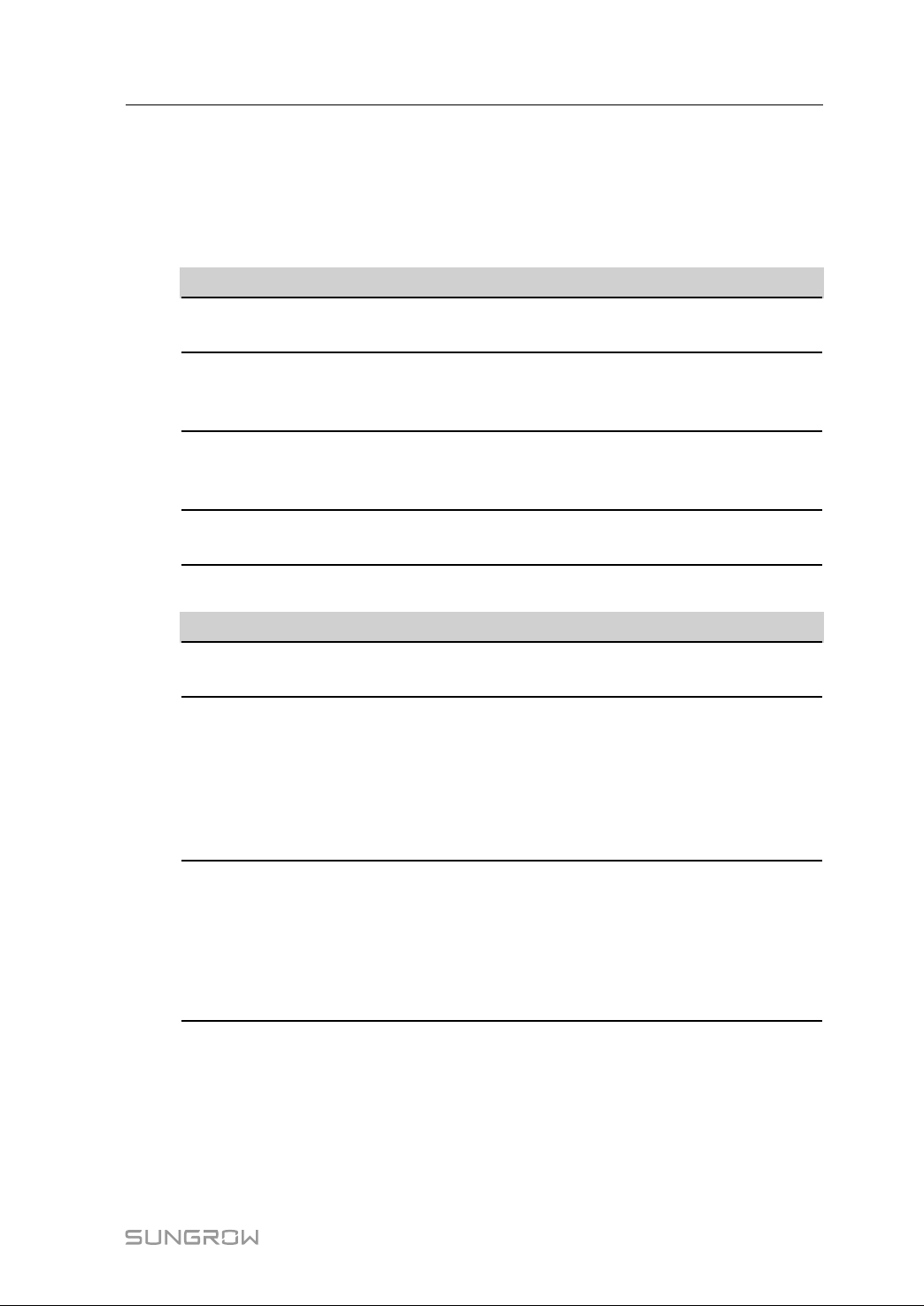
step 1 Click "Power grid scheduling" -> "Local power conditioning" to enter the corresponding
interface.
54
Page 61
User Manual 10 Grid Dispatching
step 2 Tick the option "Enable" in the upper left corner and click "Save", to enable the local
regulation function.
step 3 Select the corresponding local regulation mode, for example, active power regulation
and reactive power regulation.
table 10-1 Description of active regulation parameters
PPaarraammeetteerr DDeessccrriippttiioonn
Active power control mode The control mode is set to "Fixed value of active
power".
Power rise speed (%/min) Rising rate of active power, ranging from 8 to
6000. For specific meanings, refer to the inverter
manual.
Power drop rate (%/min) Decline rate of active power, ranging from 8 to
6000. For specific meanings, refer to the inverter
manual.
Start time Click "Add", "Modify", and "Delete" to edit the
start time of the active power fixed value.
table 10-2 Description of reactive regulation parameters
PPaarraammeetteerr
Reactive power control mode
Reactive power percentage start
time
Reactive power fixed value start
time
-- -- EEnndd
DDeessccrriippttiioonn
Includes reactive power percentage start time
and power factor fixed value
When the reactive power control mode is set to
"reactive power percentage", the start time also
needs to be set.
Method: Click "Add", "Modify", and "Delete" to
edit the start time of the reactive power
percentage.
When the reactive power control mode is set to
"power factor fixed value", the start time also
needs to be set.
Method: Click "Add", "Modify", and "Delete" to
edit the start time of the reactive power fixed
value start time.
55
Page 62
10 Grid Dispatching User Manual
10.5 BDEW
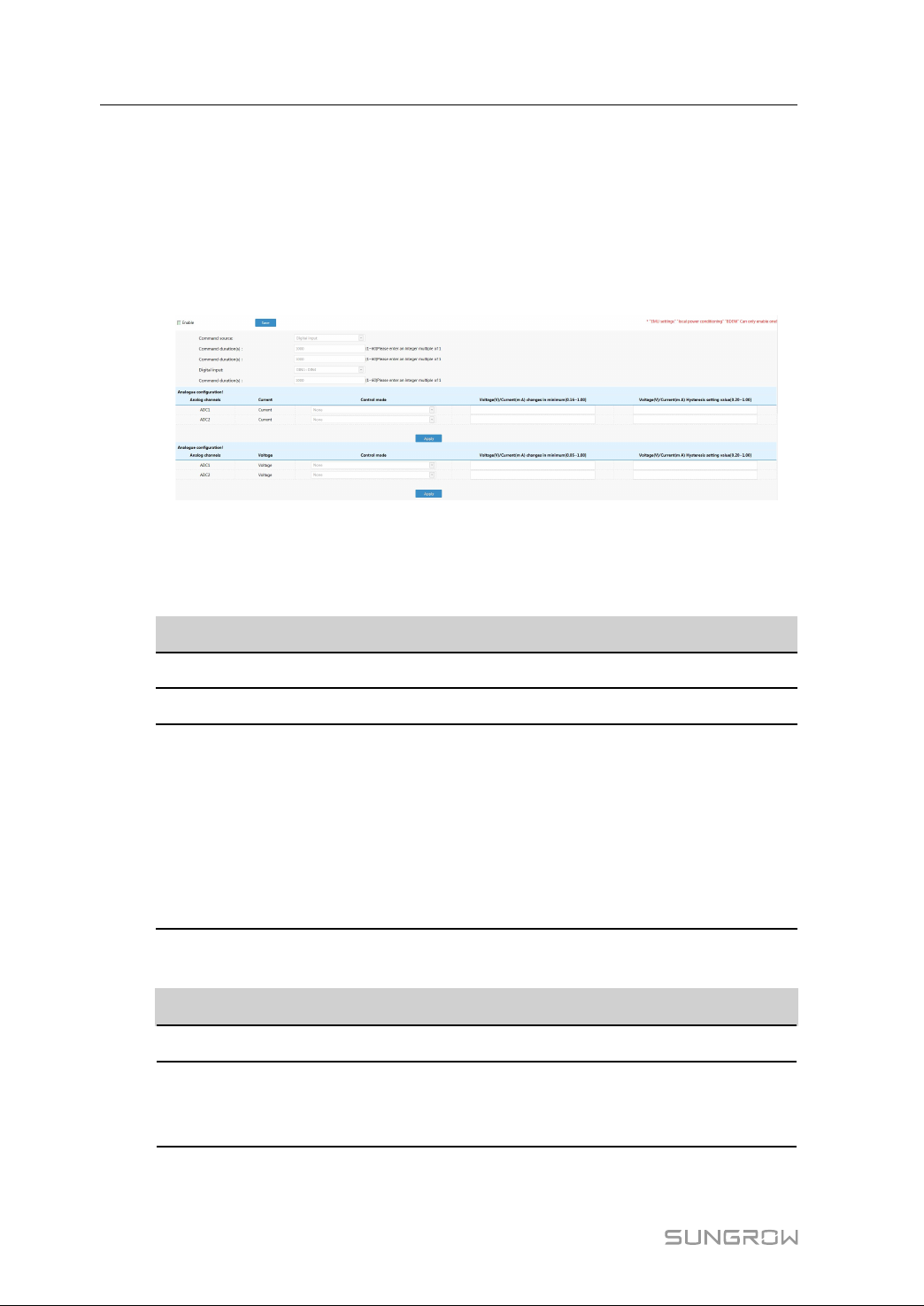
According to the BDEW standard, it is necessary to configure a digital input or an analog
input to the Logger3000, to achieve the remote grid dispatching function. The method is
as follows:
step 1 Click "Power grid scheduling" -> "BDEW", to enter the corresponding interface, as
shown in the figure below.
step 2 Tick the option "Enable", to set the parameters.
step 3 Select the corresponding command source.
When the "Command source" is set to "Digital input", set the following parameters:
PPaarraammeetteerr
Digital input
Command duration (s) Ranging from 1 to 60, integral number
DIN configuration
When the "Command source" is set to "Voltage input" or "Current input", set the
following parameters:
PPaarraammeetteerr DDeessccrriippttiioonn
Command duration (s) Ranging from 1 to 60, integral number
Analog configuration Used to set the control mode, changes in
DDeessccrriippttiioonn
Includes DIN1- DIN 4, DIN5- DIN 8, and DIN9
Used to configure the parameters of one or
multiple digital input nodes, including control
mode and percentage
Click "Add", "Modify", and "Delete" to edit the
current node parameter
If it is selected, the parameter is set to 1
If it is not selected, the parameter is set to 0
minimum, and hysteresis value of an analog
channel
56
-- -- EEnndd
Page 63
11 Maintenance
Due to the influence of ambient temperature, humidity, dust and vibration, the inner
components of the Logger3000 will be aging and worn out. To ensure the system safety
and maintain the efficiency of the Logger3000, it is necessary to carry out routine and
periodic maintenance.
All measures, which can help the Logger3000 to keep good working conditions, are
within the maintenance scope.
11.1 Safety Instructions
Only qualified personnel can perform the work described in this chapter.
Do not leave any screws, washers or other metallic parts inside the Logger3000
to avoid device damage.
After the Logger3000 stops, wait at least 5 minutes before performing any work
on it.
FFiivvee SSaaffeettyy RRuulleess
Respect the following five rules throughout the maintenance or service process to
ensure personnel safety.
• Disconnect the Logger3000 from all the external connections and internal power
supplies.
• Ensure that the Logger3000 will not be inadvertently connected.
• Ensure that the Logger3000 is voltage free with a multimeter.
• Connect necessary grounding cables.
• Cover the electrical components with insulation cloth during operation.
57
Page 64

11 Maintenance User Manual
11.2 Maintenance List
IItteemm MMeetthhoodd
Check to make sure there is no strong EMC interference device
around the Logger3000
Working
environment
Hardware
maintenance
System
cleaning
Terminal and
cable
connection
Software
maintenance
Check to make sure there is no hot source around the Logger3000.
Check to make sure there is no corrosive materials around the
Logger3000
Check to make sure the power supply voltage is normal
Check to make sure the cables are connected firmly
Check to make sure the grounding cable is grounded properly
Clean the enclosure, circuit board and the components
Check the heat dissipation hole and the ensure it is not covered
Check if the screws of the control terminals are loose. Refasten
them with screwdriver if necessary
Check if the connection copper bar or screws are discoloring
Visually check the wiring layout and the device terminal connection
Log in Web to check the device communication situation
Log in Web to check the parameter setting of the Logger3000
Log in Web to check the software version of the Logger3000
58
Page 65
12
Troubleshooting
12.1 Safety Instructions
The ground cable must be grounded reliably. Otherwise, electric shock may
occur to the operators!
12.2 Common Faults and Corrective Measures
The following table shows common faults and corresponding corrective measures. If
the fault still persists after you perform the corrective measures as described in this
manual, contact SUNGROW with the following information provided:
• Serial number of the Logger3000, date of manufacture, and software version
• Manufacture, type, configuration, and other information of device connected to the
Logger3000
• Fault information and brief description
• Picture of the fault (if possible)
FFaauulltt
Failure to log into
the Web
PPoossssiibbllee ccaauussee
1. Cable connection between
the PC and the Logger3000 is
abnormal.
2. PC network signal is
abnormal.
3. IP address of the PC is
incorrect.
4. The PC cannot normally
receive data.
CCoorrrreeccttiivvee mmeeaassuurree
1. Check whether the PC is
normally connected to the
port ETH1 of the Logger3000.
2. Check whether the network
signal icon of the PC is
abnormal, like this
3. Manually set the IP address
to be within 0 network
segment, for example,
192.168.0.123.
4. Use the shortcut key win+R
to call up the running
command box and enter "-
ping 192.168.0.100", to
check whether the PC can
receive data packets.
.
59
Page 66
12 Troubleshooting User Manual
FFaauulltt
Communication
failure between the
Logger3000 and
devices connected
to it
Data
communication
between the
Logger3000 and
background via
ModbusRTU failed
PPoossssiibbllee ccaauussee
5. Confrontation with network
card or anti-virus software
occurs.
1. The RS485 cable
connecting the device and
the Logger3000 is abnormal.
2. Configuration of the serial
port is inconsistent with the
RS485 parameters of the
device.
3. The current device is an
inverter, and the inverter
cannot be added to the Web
system in automatic search
manner.
4. Communication connection
status between the
Logger3000 and the device is
abnormal.
1. The RS485 cable
connecting the device and
the Logger3000 is abnormal.
CCoorrrreeccttiivvee mmeeaassuurree
5. If the PC cannot receive
data packets, disable other
network cards, anti-virus
software or fireproof wall, and
try the login again.
1. Check the RS485 cable
connecting the device and
the Logger3000 and ensure it
is not in short circuit, open
circuit, or reverse connection
between RS485–A and
RS485–B.
2. Log into the Web, and click
"Settings" -> "Serial port
settings" to check whether
the port configuration is
consistent with the RS485
parameters of the device.
3. Manually input the inverter
address to add the inverter to
the Web system.
4. Log into the Web, and click
"Monitoring", to check
whether the communication
status icon is like this
and check whether repeated
addresses are allocated to
the same port.
If the fault persists, contact
SUNGROW.
1. Check the RS485 cable
connecting the device and
the Logger3000 and ensure it
is not in short circuit, open
circuit, or reverse connection
between RS485–A and
RS485–B.
,
60
Page 67

User Manual 12 Troubleshooting
FFaauulltt
No data exchange
between the and
background via
ModbusTCP
PPoossssiibbllee ccaauussee
2. COM port parameter is
incorrectly set on the web
interface.
3. Collection address of the
device does not match with
access address.
4. Protocol configuration of
the background is
inconsistent with that of the
device.
1. Network connection
between the and background
is incorrect.
2. Configuration of port ETH2
of the is incorrect.
3. Collection address of the
device does not match with
forwarding address.
4. Background IP is
incorrectly set.
CCoorrrreeccttiivvee mmeeaassuurree
2. Log into the Web, and click
"Settings" -> "Serial port
settings" to check whether
the COM port is set to "-
Forwarding background".
Check whether the serial port
parameter is correct.
3. Log into the Web, and click
"Settings" -> "Modbus
service settings" to ensure
that the collection address of
the matches with the access
address.
4. Ensure that the protocol
configuration of the
background is consistent with
that of the device.
1. Check that the network
connection between the and
the background is correct.
2. Set the IP address of the
port ETH2 of the to the one
that the background needs to
access.
3. Log into the Web, and click
"Settings" -> "Modbus
service settings" to ensure
that the collection address of
the matches with the
forwarding address.
4. Log into the Web, and click
"Settings" -> "Network
settings" to check whether
the background IP is set to
fixed IP. It is recommended to
set the background IP
parameter of the to 0.0.0.0 or
the actual background IP
address.
61
Page 68

12 Troubleshooting User Manual
FFaauulltt
No data exchange
between the and
background via
IEC104
No data exchange
between the and
iSolarCloud
Remote inverter
upgrading failed
PPoossssiibbllee ccaauussee
5. Protocol configuration of
the background is
inconsistent with that of the
device.
1. Network connection
between the and background
is incorrect.
2. IP address of the
forwarding device or
background IP address is
incorrect.
3. The communication device
is abnormal.
4. Background parameters
are incorrectly configured.
1. System time of the is
incorrect.
2. The port ETH2 is abnormal.
3. Communication between
the and devices like inverter
and combiner box is
abnormal.
1. The current inverter does
not support remote upgrading
function, or the upgrading file
is inconsistent with the actual
device type.
CCoorrrreeccttiivvee mmeeaassuurree
5. Ensure that the protocol
configuration of the
background is consistent with
that of the device.
1. Check that the network
connection between the and
the background is correct.
2. Log into the Web, and click
"Settings" -> "IEC104
service settings" to check that
the access address is set to
0.0.0.0.
It is recommended to set the
background IP parameter of
the to 0.0.0.0 or the actual
background IP address.
3. Check that the
communication device is
normal.
4. Ensure that the
background parameters are
correctly configured.
1. Log into the Web, and click
"Settings" -> "Time settings"
to check whether the time
setting is correct.
2. Users access the Internet
via the port ETH2.
3. Check that the can
normally communicate with
devices such as inverter and
combiner box.
1. Ensure that the current
inverter supports the remote
upgrading function, and the
sgu file is consistent with the
actual device type.
62
Page 69
User Manual 12 Troubleshooting
FFaauulltt
PPoossssiibbllee ccaauussee
2. The upgrading file is
abnormal.
3. The type of to-beupgraded inverter is
inconsistent with the
upgrading file.
4. Communication connection
is abnormal.
1. Communication connection
is abnormal.
CCoorrrreeccttiivvee mmeeaassuurree
2. The upgrading file is invalid,
for example, the file is
encrypted or the file is named
incorrectly.
3. Check whether the type of
the to-be-upgraded inverter is
inconsistent with the
upgrading file.
4. Check whether the
communication cable is
correctly connected, and try
to upgrade the inverter again
if so.
If the fault persists, contact
SUNGROW.
1. Log into the Web, and click
"Monitoring", to check
whether the communication
status icon is normal, like this
Remote parameter
setting failed
2. The current operation
mode of the inverter does not
support the parameter setting.
.
2. Identify the current
operation mode of the
inverter. For example, the
active power rising speed and
drop speed can be set only
when the speed control
switch of the inverter is
enabled.
63
Page 70

13
FAQ
Q1. How many types of communication ports does the Logger3000 support, what are
the corresponding ports, and how to set the port parameters?
TTyyppee
Ethernet
RS485 A1B1~A6B6
PLC PLC
Q2. What are the forwarding protocols supported by the Logger3000?
PPrroottooccooll
ModbusRTU/ModbusTCP
IEC104
PPoorrtt
ETH1
ETH2
PPaarraammeetteerr sseettttiinngg
Reserved
Default IP: 192.168.1.100; subnet mask:
255.255.255.0
Gateway: 192.168.1.254
DNS1: 1.2.4.8
DNS2: 8.8.8.8
Default Baud rate: 9600
Check bit: Null
Data bit: 8
Stop bit: 1
Default Baud rate: 115200
Check bit: Null
Data bit: 8
Stop bit: 1
DDeessccrriippttiioonn
The Logger3000 sends the collected data of devices (-
such as inverter, combiner box, Meteo Station) to the
background. The background allocates forwarding
addresses to theses devices, thereby accessing and
obtaining the data of the devices.
1. Add or search devices on the Web interface (such
as inverter, combiner box, Meteo Station).
2. Export the IEC104 point table by clicking "Settings"
-> "IEC104 service settings". The point table shows
measuring point information of devices.
64
Q3. How to log into the system via R&D account and how to obtain the password?
Generally, the O&M users have access to most of onsite configurations. If there should
be any needs to use the R&D account, contact SUNGROW to obtain a temporary
password which is valid only as of this day.
Q4. How to connect multiple Logger3000s to the background through the network?
Page 71
User Manual 13 FAQ
1 Logger3000s closer to the Ethernet switch (<100m) are connected to the Ethernet
switch by using network cables.
2 Logger3000s relatively far away from the Ethernet switch (>100m) are connected
to the Ethernet switch by using routed fiber optic cables.
3 After cable connection, IP address of the multiple Logger3000s should be set to be
within the same network segment, without repeated addresses.
65
Page 72

14
Appendix A: Technical Data
CCoommmmuunniiccaattiioonn
Inverter communication RS485
PC communication
Max. Communication Range
RS485/Ethernet
Interface Design
RS485
Digital input port 16
Ethernet port 2
Power Supply
Power module 110 V ~ 277 V (50 / 60 Hz)
Adapter input voltage 9 V – 24 V
Power consumption Typ. 8 W / Max. 15 W
Environmental Conditions
Operating Temperature
Storage Temperature
Relative humidity ≤ 95 %(non-condensing)
Max.operating altitude 3000m
Protection class IP20
Memory
Internal
General Data
Dimension (W x H x D) 440 x 44 x 241mm
Weight 3 kg
Installtion method Rack-mounted installation, wall mounted
Man-Machine Interaction WEB
Language Chinese, English, Japanese
Compliance UL 60950-1, FCC, IEC 62109-1, IEC 61000-6-
Ethernet / RS485
1000 m /100 m
6
-30 ℃ to +60 ℃
-40 ℃ to +80 ℃
4 GB circulating memory
installation
2/-4
66
Page 73
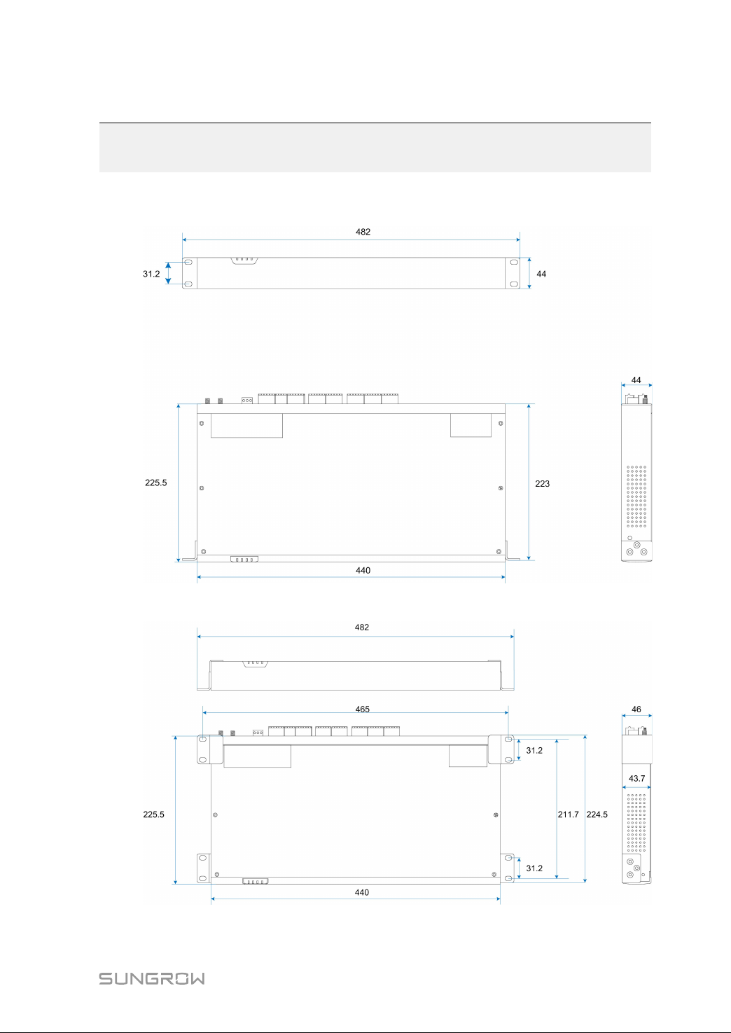
15
Appendix B: Related Drawings
RRaacckk--mmoouunntteedd ddrraawwiinnggss
WWaallll--mmoouunntteedd ddrraawwiinnggss
67
Page 74
16
Appendix C: General Information
16.1 Quality Guarantee
SUNGROW shall service or replace the faulty product for free within the warranty period.
EEvviiddeennccee
Within the warranty period, SUNGROW shall require the customer to present the
purchase invoice and date. The trademark on the product shall be clearly visible, and
SUNGROW shall hold no liability if otherwise.
EExxcclluussiioonn ooff LLiiaabbiilliittyy
• The free warranty period for the whole machine/components has expired
• The device is damaged during transport
• The device is installed, altered, or operated incorrectly
• The device operates in an environment harsher than that described in this manual
• The fault or damage is caused due to installation, maintenance, alteration, or
disassembly performed by persons not from SUNGROW
• The fault or damage caused by using non-standard components or software or
using components or software not from SUNGROW
• The installation and operation do not comply with stipulations of relevant international
standards
• The damage is caused by unpredictable factors
For the foregoing faults or damages, SUNGROW can provide a paid service at the
request of the client after judgment.
The dimensions and parameters of the device are subject to changes without
notification, and reference can be made to the latest document.
SSooffttwwaarree LLiicceennsseess
• It is prohibited to use data contained in firmware or software developed by
SUNGROW, in part or in full, for commercial purposes by any means.
• It is prohibited to perform reverse engineering, cracking, or any other operations that
compromise the original program design of the software developed by SUNGROW.
16.2 Contact Information
Should you have any question about this product, please contact us.
68
Page 75

User Manual 16 Appendix C: General Information
We need the following information to provide you the best assistance:
• Type of the device
• Serial number of the device
• Fault code/name
• Brief description of the problem
China (HQ)
Sungrow Power Supply Co., Ltd
Hefei
+86 551 65327834
Brazil
SungrowDo Brasil
Sao Paulo
+55 11 2366 1957
Germany
Sungrow Deutschland GmbH
München
+49 89 324 914 761
India
Sungrow (India) Private Limited
Gurgaon
+9108041201350
Japan
Sungrow Japan K.K.
Tokyo
+ 81 3 6262 9917
Malaysia
Sungrow SEA
Selangor Darul Ehsan
+6019897 3360
Australia
Sungrow Australia Group Pty. Ltd.
Sydney
+61 2 9922 1522
France
Sungrow France – Siege Social
Paris
Greece
Service Partner – Survey Digital
+30 2106044212
Italy
Sungrow Italy
Milano
Korea
Sungrow Power Korea Limited
Seoul
+827077191889
Philippines
Sungrow Power Supply Co., Ltd
Mandaluyong City
+639173022769
69
Page 76

16 Appendix C: General Information User Manual
Thailand
SungrowThailand Co., Ltd.
Bangkok
+66891246053
Romania
Service Partner - Elerex
+40 241762250
UK
Sungrow Power UK Ltd.
Milton Keynes
+44 (0) 0908 414127
Vietnam
Sungrow Vietnam
Hanoi
+84 918 402 140
Spain
Sungrow Ibérica S.L.U.
Navarra
Turkey
Sungrow Deutschland GmbH Turkey
Istanbul Representative Bureau
Istanbul
+90 2127318883
U.S.A, Mexico
Sungrow USA Corporation
PhoenixArizona
+1833 7476937
70
Page 77

Add: No.1699 Xiyou Rd.,New & High Technology Industrial Development Zone, 230088,Hefei, P. R. China.
Tel: +86 551 6532 7834 / 6532 7845Web: www.sungrowpower.com E-mail: [email protected]
Sungrow Power Supply Co., Ltd.
Specifications are subject to changes without advance notice.
 Loading...