

Page 1

Logger1000A/ Logger1000B
Data Logger
User Manual
Logger1000A_B-UEN-Ver12-201910 Version: 1.2
Page 2

Page 3

Content
1 About this Manual ................................................................... 1
1.1 Intended Use ........................................................................................................ 1
1.2 Target Group ........................................................................................................ 1
1.3 How to Use This Manual ................................................................................... 1
1.4 Symbol Explanations ......................................................................................... 2
2 Safety Instruction .................................................................... 3
3 Product Introduction ............................................................... 5
3.1 Function Description ......................................................................................... 5
3.1.1 Brief Product Introduction .................................................................................. 5
3.1.2 Network ing Application ...................................................................................... 6
3.2 Appearance .......................................................................................................... 8
3.3 Dimensions ........................................................................................................... 9
4 Installation Flow..................................................................... 10
5 Mechanical Installation ......................................................... 11
5.1 Unpacking and Inspection ............................................................................ 11
5.2 Installation Location Requirements ........................................................... 12
5.3 Installation Tools .............................................................................................. 13
5.4 Installing Logger1000 .................................................................................... 13
5.4.1 Wall-Mounted Installation ................................................................................14
5.4.2 Guide Rail-Mounted Installation .....................................................................15
5.5 Installing Antenna ........................................................................................... 17
5.6 Installing Power Box ....................................................................................... 17
6 Electrical Connection ............................................................. 19
6.1 Safety Instructions ........................................................................................... 19
6.2 Port Introduction ............................................................................................. 19
6.3 Connection to PV Devices ............................................................................. 20
6.3.1 Connection to Inverter ......................................................................................20
I
Page 4

6.3.2 Connection to Energy Meter ........................................................................... 24
6.3.3 Connection to Meteo Station .......................................................................... 24
6.4 Connection to Background ........................................................................... 25
6.5 Connection to Micro-SIM............................................................................... 26
6.6 Connection to Power Box .............................................................................. 26
6.7 Cable Routing Requirements ....................................................................... 28
7 Commissioning ...................................................................... 30
7.1 Inspection before Commissioning ............................................................. 30
7.2 Commissioning Steps ..................................................................................... 30
8 Web Interface ......................................................................... 32
8.1 Running Requirements .................................................................................. 32
8.2 Login Steps ........................................................................................................ 32
8.2.1 WiFi Login............................................................................................................... 32
8.2.2 Ethernet Login ...................................................................................................... 33
8.3 Web Main Interface ......................................................................................... 33
8.4 Web Menu .......................................................................................................... 34
8.5 Operation Procedure ...................................................................................... 35
8.6 Overview............................................................................................................. 36
8.6.1 General Information ........................................................................................... 36
8.6.2 Current Alarms...................................................................................................... 37
8.7 Device Monitoring ........................................................................................... 37
8.7.1 RealTime Values ................................................................................................... 37
8.7.2 DC Data ................................................................................................................... 37
8.7.3 Initial Parameter ................................................................................................... 37
8.7.4 Protection Parameter ......................................................................................... 38
8.7.5 General Parameter .............................................................................................. 38
8.7.6 Device Instruction ............................................................................................... 38
8.7.7 Device Information ............................................................................................. 39
8.8 Device Maintenance ....................................................................................... 39
8.8.1 Device List .............................................................................................................. 39
8.8.2 Firmware Update ................................................................................................. 40
II
Page 5

8.8.3 Inverter Log ...........................................................................................................41
8.9 History Data ....................................................................................................... 41
8.10 System ................................................................................................................. 41
8.10.1 Running Information .......................................................................................41
8.10.2 System Maintenance ........................................................................................41
8.10.3 Remote Maintenance.......................................................................................42
8.10.4 Message Export .................................................................................................43
8.10.5 System Time ........................................................................................................43
8.10.6 Forwarding Configuration ..............................................................................44
8.10.7 Interface ...............................................................................................................48
8.11 About ................................................................................................................... 50
9 Grid Dispatching Function .................................................... 51
9.1 Function Description ...................................................................................... 51
9.2 Interface Description ...................................................................................... 52
9.2.1 Digital Control Interface ....................................................................................52
9.2.2 Analog Control Interface ...................................................................................54
9.2.3 DRM Control Inter face .......................................................................................54
9.3 Power Control ................................................................................................... 55
9.3.1 Active Power ..........................................................................................................55
9.3.2 Reactive Power .....................................................................................................60
9.3.3 Emergency Button ..............................................................................................64
10 Device Maintenance .............................................................. 65
10.1 Safety Instructions ........................................................................................... 65
10.1.1 Safety Rules .........................................................................................................65
10.1.2 Five Safety Rules ................................................................................................65
10.2 Maintenance ..................................................................................................... 66
10.3 Troubleshooting .............................................................................................. 66
11 Appendix ................................................................................ 68
11.1 Technical Data .................................................................................................. 68
11.2 Quality Guarantee ........................................................................................... 68
11.3 Contact Information ....................................................................................... 70
III
Page 6

Page 7
1 About this Manual
This manual is valid for the following data loggers researched and manufactured by
Sungrow Power Supply Co., Ltd.
Logger1000A (4G version)
Logger1000B (non-4G version)
The foregoing Loggers are referred to as the "Logger1000" for short unless
otherwise specified.
1.1 Intended Use
This manual is intended to provide users with detailed information on the
Logger1000 as well as installation, operation, and maintenance description.
1.2 Target Group
This manual is applicable to technical personnel who are responsible for the
installation, operation and maintenance of the Logger1000 and to users who need
to perform daily operation. Readers should have some electrical knowledge and be
familiar with electrical principles and electrical components. This manual does not
cover the electrical connections of the inverter and the Meteo Station or related
safety instructions. For the details of the electrical connections of these devices,
refer to the corresponding manuals.
1.3 How to Use This Manual
Read this manual carefully before performing operation on the device. This manual
must be stored at hand and available at all times.
All rights reserved including the pictures, symbols, and markings used in this
manual. Any reproduction or disclosure, even partially, of the contents of this
manual is strictly prohibited without prior written authorization of SUNGROW. The
content of the manual will be periodically updated or revised as per the product
development. It is probably that there are changes in manuals for the subsequent
module edition. If there any mismatch between the product and its manual, the
1
Page 8
1 About this Manual User Manual
, could result in
actual product shall prevail and the manual of the latest version can be obtained
from SUNGROW.
1.4 Symbol Explanations
This manual contains important safety and operational instructions that must be
accurately understood and respected during the installation and maintenance of
the equipment.
To ensure the optimum use of this manual, note the following explanations of the
symbols used.
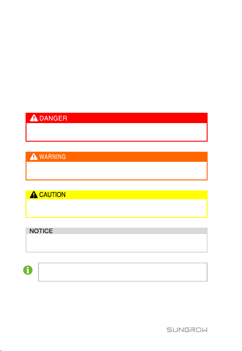
DANGER indicates a hazard with a high level of risk which, if not avoided,
will result in death or serious injury.
WARNING indicates a hazard with a medium level of risk which, if not
avoided, could result in death or serious injury.
CAUTION indicates a hazard with a low level of risk which, if not avoided,
could result in minor or moderate injury.
NOTICE indicates a situation which, if not avoided
equipment or property damage.
NOTE indicates additional information, emphasized contents or tips to help
you solve problems or save time.
2
Page 9
2 Safety Instruction
This chapter mainly introduces safety instructions that need to be respected during
the operation of Logger1000.
The Logger1000 has been designed and tested strictly according to international
safety regulations. As electrical and electronic equipment, the Logger1000 must be
installed, commissioned, operated, and maintained in strict accordance with related
safety instructions. Incorrect operation or misuse of the device may cause:
damage to personnel safety of the operators or the third party
damage to the Logger1000 or other properties belong to the operators or the
third party
Therefore, the following safety instructions must be read and always kept in mind
prior to any work. All detailed work-related safety warnings and notes will be
specified at the critical points in corresponding chapter.
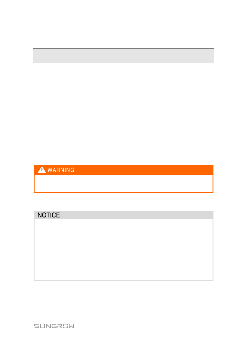
All operation and electrical work must only be performed by qualified
personnel.
Before Installation
After receiving the device, please check if there is damage caused during
transport. Contact SUNGROW or the forwarding company once any problem
is detected.
The related operators must be familiar with the safety instructions in this
manual and other safety regulations about the installation, operation and
maintenance of the Logger1000.
Move, transport, install, operate, and maintain the Logger1000 correctly
and appropriately.
3
Page 10
2 Safety Instruction User Manual
spare parts not sold or
During Installation
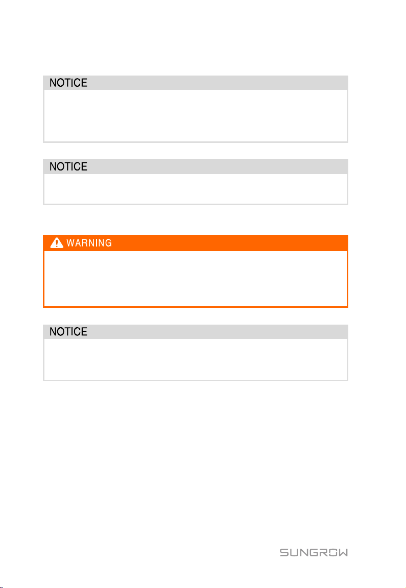
The Logger1000 can only be used as described in this manual. Altering the
product without authorization or using
recommended by SUNGROW may lead to fire, electric shock or other
damages.
Disconnect all electrical connections and the upstream input switch and
make sure the Logger1000 is voltage-free during installation.
Maintenance and Replacement
The maintenance of the Logger1000 can only be performed by qualified
personnel from service dept. of SUNGROW or other qualified personnel.
User can never maintain or replace the modules and other parts. Serious
personal injury or property loss may follow if otherwise.
Never replace the internal components of the Logger1000 without
authorization. SUNGROW shall not be held liable for any possible damage
caused by ignorance of this warning.
4
Page 11
3 Product Introduction
3.1 Function Description
3.1.1 Brief Product Introduction
The Logger1000 is a device used for data collection, power control, and protocol
conversion for inverters and other PV equipment in the PV plant. The device is also
integrated with communication gateway and plant O&M function.
The Logger1000 is featured as flexible networking, auxiliary maintenance, and easy
operation.
Flexible networking
Support of RS485, Ethernet, and WiFi communication
Support of access by various environment sensors, energy meters, Meteo
Stations, inverters, and other equipment
Auxiliary maintenance
Support of batch inverter parameter setting and software upgrading
Support of remote desktop function, lower maintenance costs
Support of grid control instruction and power factor control
Support of local real-time monitoring, unnecessary to connect the Internet
Easy operation
Auto search and allocation of inverter address
Embedded web operation interface, support of mobile phone access, free
download of the App
5
Page 12
3 Product Introduction User Manual
3.1.2 Networking Application
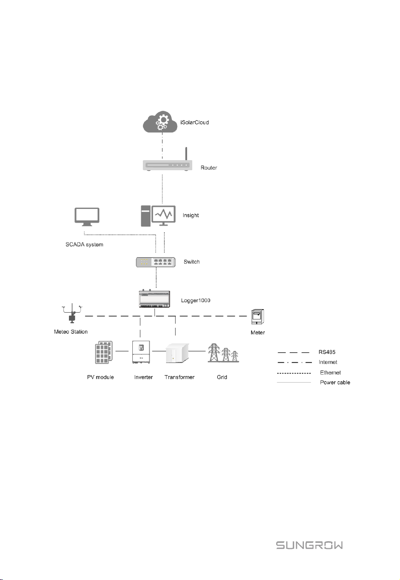
As shown in the figure below, the Logger1000 can be connected to iSolarCloud via a
switch.
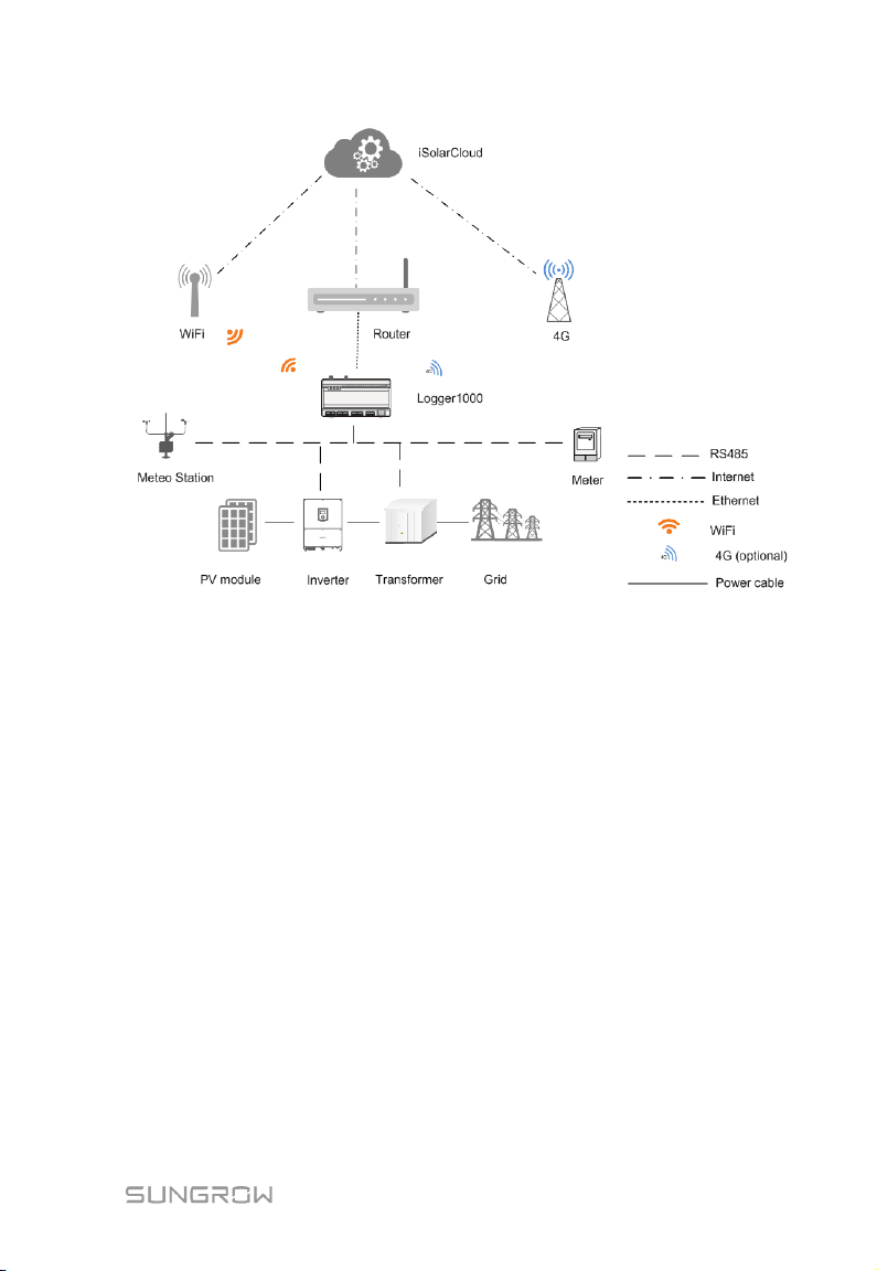
The Logger1000 can be connected to iSolarCloud via the router or connected to the
iSolarCloud via the WiFi or 4G network.
6
Page 13
User Manual 3 Product Introduction
The Logger1000 supports various communication manners such as WiFi and 4G.
The Logger1000 is connected to various environment sensors, energy meters,
Meteo Stations, and inverters in the PV power generation system via an RS485
bus.
Users can access the Web interface via mobile phone or PC, on which parameter
configuration and remote on-line upgrading can be performed.
The Logger1000 can transmit data to iSolarCloud and forward background
instructions to downstream devices.
The Logger1000 is equipped with grid dispatching function, including active
power control, reactive power regulation, etc.
7
Page 14
3 Product Introduction User Manual
Front view
Rear view
Bottom view
Side view
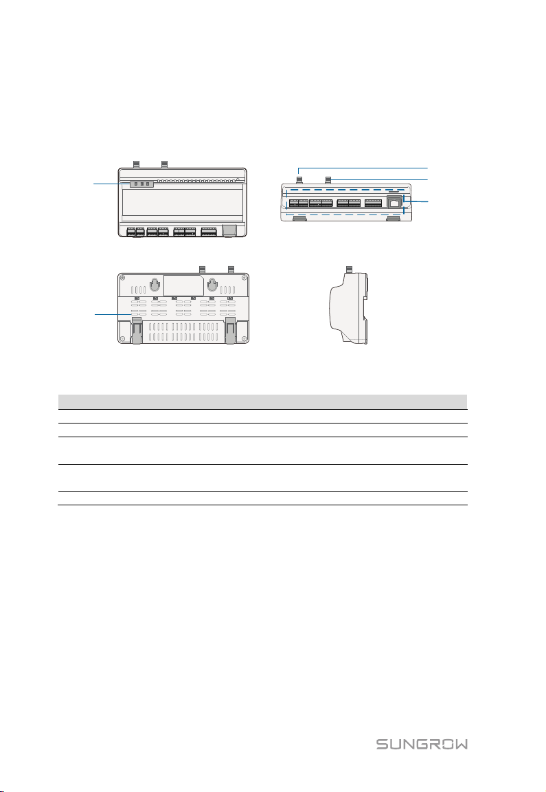
A
B
C
D
E
Item
Designation
Description
A
Indicator
Indicate the running state of the Logger1000
B
Vent
-
WLAN antenna mounting
hole
4G antenna mounting
hole
E
Wiring terminal
Refer to "Tab. 6-1Port description"
3.2 Appearance
Views of the Logger1000 are shown in the following figure.
C
D*
Fig. 3-1 Appearance
-
-
Note: D* is 4G antenna mounting hole. The Logger1000A is provided with the hole
while the Logger1000B is not. Specifically, refer to the actual product received. In
the following, description is given by using the Logger1000A as an example.
8
Page 15
User Manual 3 Product Introduction
Indicator
(print)
No external power supply
connected
Slow flash
(Green)
Slow flash
(Red)
Steady on
(Red)
4G indicator
Off
No data communication
Steady on
4G connected successfully
Slow flash
Data communication in process
Off
No data communication
Steady on
WiFi connected successfully
Slow flash
Data communication in process
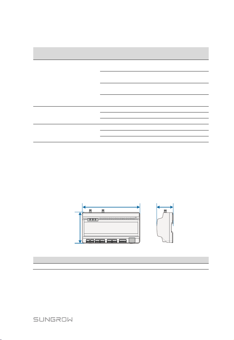
Width (W)
Height
(H)
Depth (D)
Width (W)
Height (H)
Depth (D)
200mm
110mm
60mm
Indicator
LED color LED status Description
Off
Running
indicator (RUN)
Red/green
Normal running
Device alarm
Logger1000 running fault
(4G)
WLAN indicator
(WLAN)
Blue
Blue
Note: * Only the Logger1000A is equipped with the 4G indicator.
Slow flash means that the indicator flashes once every second.
Slow flash of the communication indicator indicates data communication in process. If
there has been no data communication with iSolarCloud for 10s, the indicator will
keep steady on.
3.3 Dimensions
Fig. 3-2 Dimensions
9
Page 16
Mechanical installation
Electrical installation
Check before commissioning
Commissioning steps
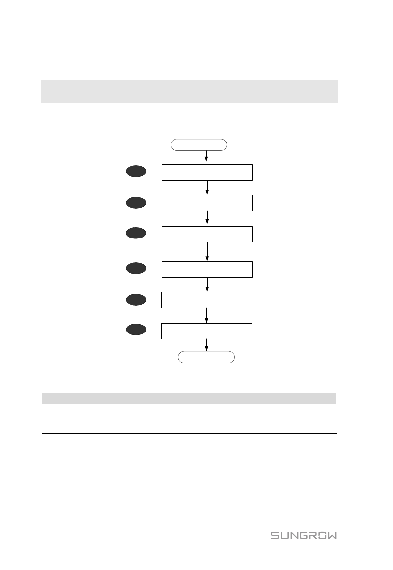
Start
Ends
1
2
Unpacking and Inspection
4
3
5
6
Installation location selection
No.
Procedure
Reference chapter
1
Unpacking and inspection
5.1 2 Installation location selection
5.2 3 Mechanical installation
5.4~5.6
4
Electrical installation
6 5 Check before commissioning
7.1 6 Commissioning steps
7.2
4 Installation Flow
The following figure shows the overall installation flow of Logger1000.
Tab. 4-1 Description of the installation flow
10
Fig. 4-1 Installation flow
Page 17
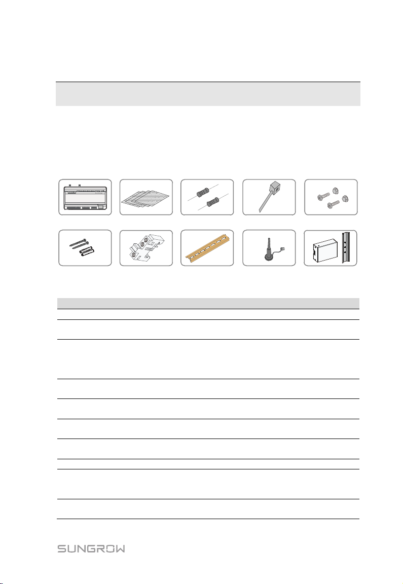
A
B
D
G
C
E
F
H
I
J
Item
Designation
Description
A
Logger1000
Logger1000
Quick User Manual, quality certificate, packing list, product
n terminal
6x120Ω (Note: if there are more than 15 devices
ected on the RS485 bus, it is recommended to
lines at the head or tail end of the bus)
Nylon cable
tie
Fastener
assembly
4 sets, M4X16, used for wall-mounting to fasten the device
on the metal surface
Expansion
bolt
4 sets, ST4.8X19, used for wall-mounting to fasten the
device on the concrete wall
Terminal
fastener
2 sets, E/UK-1201442, fixed on the guide rail to prevent
the Logger1000 from moving
H
Guide rail
Length: 240mm
WLAN
4G antenna
The Logger1000A is provided with the 4G antenna
refer to the actual product received.
Converters the AC current into DC current
Length of supporting guide rail: 170mm
5 Mechanical Installation
5.1 Unpacking and Inspection
Check the scope of delivery for completeness according to the packing list. The
following items should be included.
Fig. 5-1 Scope of delivery
B Documents
C
D
E
F
G
I
J Power box
Communicatio
resistor
antenna
11
test report, and warranty card
conn
connect a 120Ω terminal resistor in parallel on the A and B
Used to tie cables
mounting hole while Logger1000B is not. Specifically,
Page 18
5 Mechanical Installation User Manual
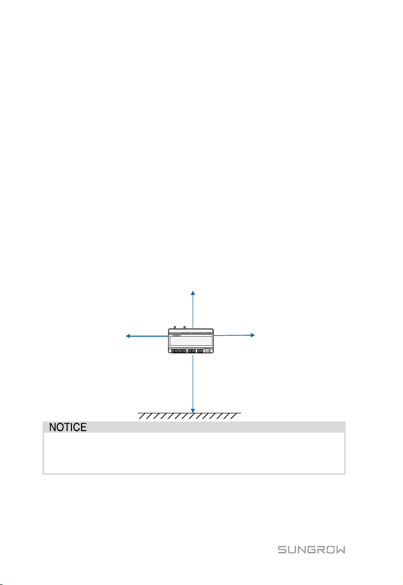
≥500mm
≥1500mm
≥500mm
≥500mm
Ground
Logger1000, users should add corresponding communication SPD
5.2 Installation Location Requirements
Selecting an optimal installation location for the Logger1000 is critical to safe
operation, long service life, and sound performance.
Take the following requirements into account when selecting the installation
location:
With the ingress of protection IP 20, the Logger1000 can be installed only
indoors.
Ambient temperature range: -30℃ to +60℃.
The relative humidity should not exceed 95%. If otherwise, the internal
components will be damaged.
Take anti-moisture and anti-corrosion measures.
Ensure that enough space is reserved around the Logger1000. The installation
location should be 1,500mm above the ground surface, and maintenance
clearance of at least 500mm should be reserved. Minimum clearances are shown
in the figure below.
When there are external devices (such as Meteo Station) connected to the
according to onsite condition.
12
Page 19
User Manual 5 Mechanical Installation
Type
Tool
Utility knife
Marker
Measuring tape
Protective
Dust mask
Goggles
Vacuum
-
Hammer drill
Electric
Wire stripper
Wire clipper
Phillips
Rubber mallet
Crimping tool
-
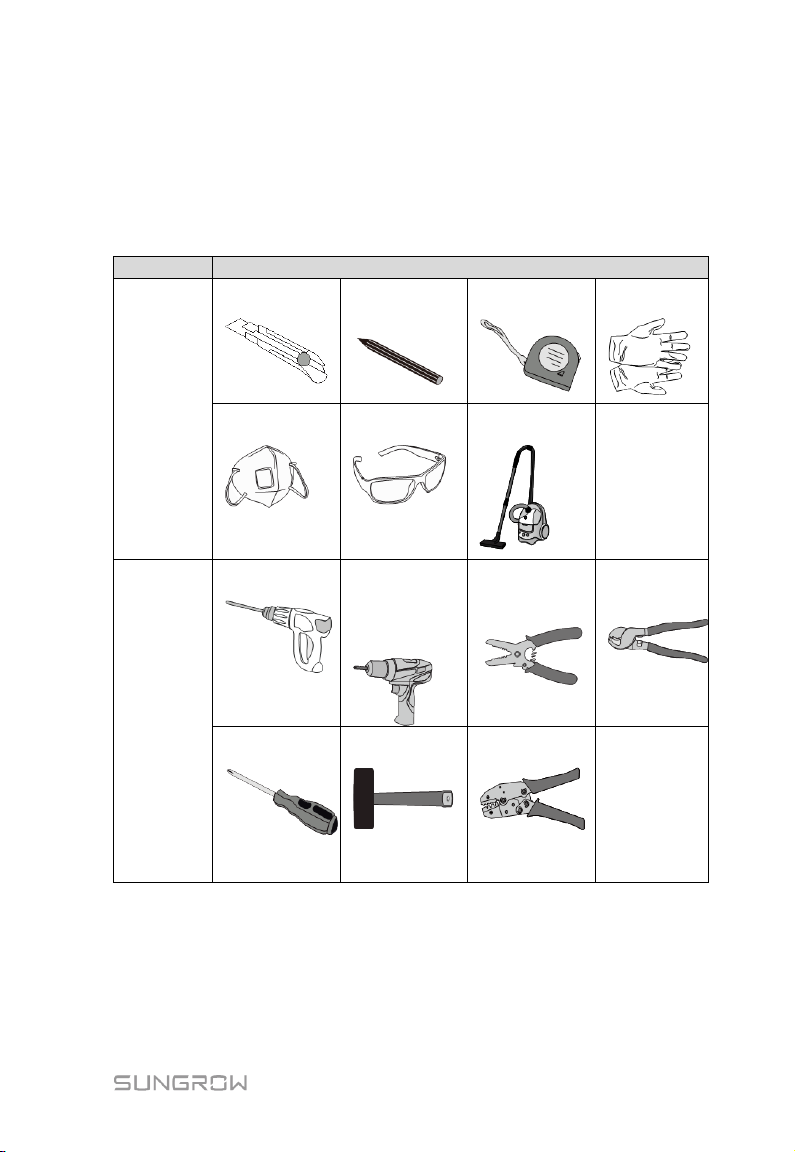
5.3 Installation Tools
Installation tools include but are not limited to the following recommended ones. If
necessary, use other auxiliary tools on site.
General
tools
Installation
tools
screwdriver
screwdriver
Specification:
M4
cleaner
gloves
5.4 Installing Logger1000
The Logger1000 can be installed in the wall-mounting manner or guide
rail-mounting manner, and users can select either one according to onsite
condition.
13
Page 20
5 Mechanical Installation User Manual
Mount the Logger1000 onto the concrete wall or metal surface
Mounting
hole
83mm
83mm
Concrete wall
83mm
Metal surface
Concrete wall
Metal surface
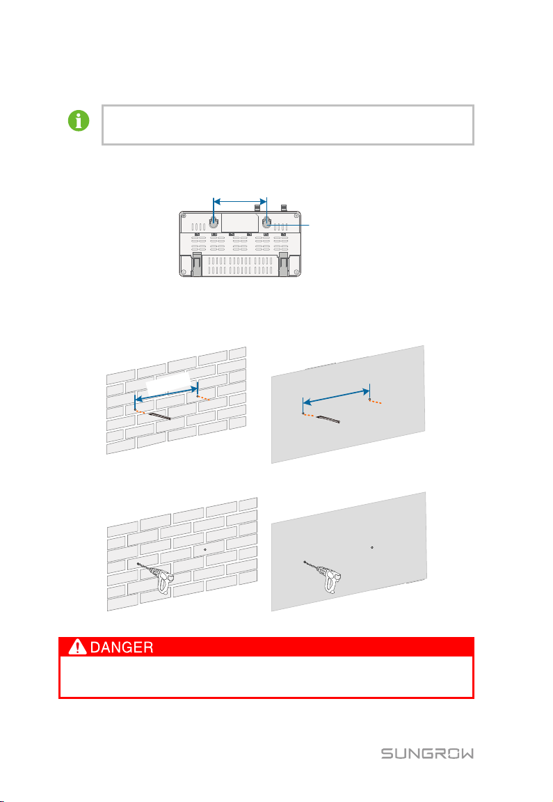
5.4.1 Wall-Mounted Installation
according to onsite conditions.
Mount the Logger1000 onto the wall via the wall-mounting holes (as shown in the
figure below) on the back of it.
Fig. 5-2 Wall-mounting hole dimension
Select an appropriate installation surface.
Step 1
Step 2 Mark positions for drilling holes with a marker.
Step 3 Drill the holes with a drill according to the marked positions.
Avoid drilling holes in the utility pipes and/or cables attached to back of the
wall!
14
Page 21
User Manual 5 Mechanical Installation
If the Logger1000 is installed onto the metal surface, skip performing
Operation personnel should wear goggles and dust mask throughout the
drilling process to avoid dust inhalation or contact with eyes.
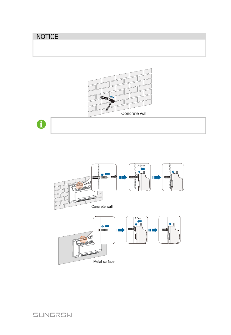
Step 4 Secure the expansion bolts into the holes with a rubber mallet.
this step.
Step 5 Fix the screw or bolt on the installation surface, where the screw protrudes
from the wall surface by about 5mm.Hang the Logger1000 onto the screws
on the concrete wall or metal surface via the wall-mounting holes on the
back of Logger1000.
Check and ensure that the Logger1000 is firmly installed.
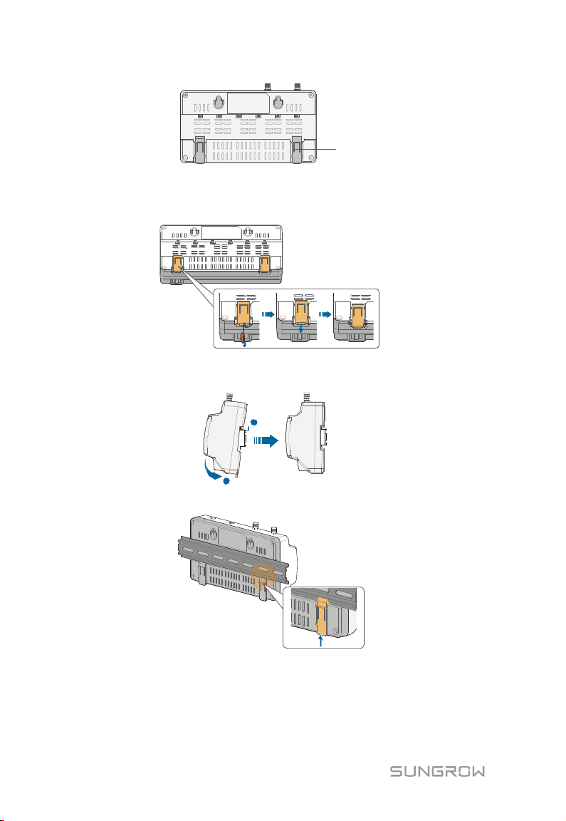
5.4.2 Guide Rail-Mounted Installation
Secure the Logger1000 via the rail buckles (as shown in the figure below) on the
back of it.
15
Page 22
5 Mechanical Installation User Manual
Buckle
1
2
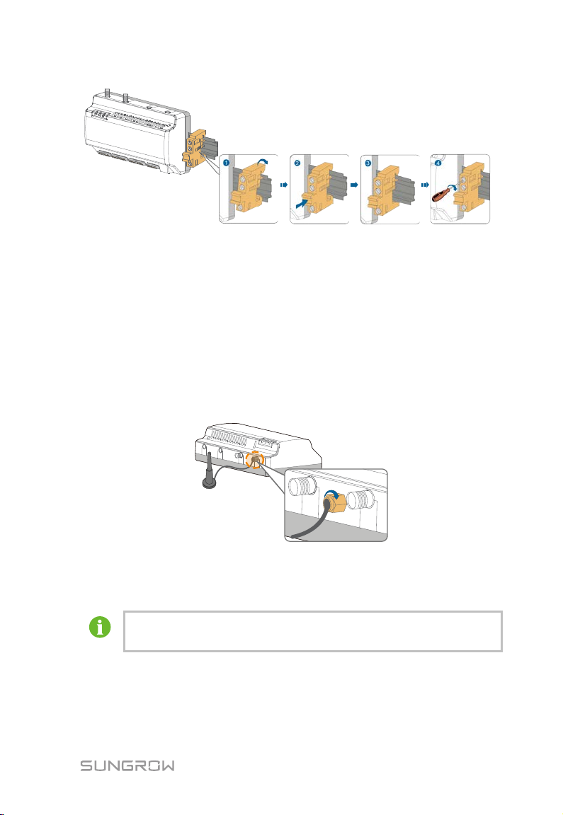
Step 1 Install and secure the guide rail at the appropriate location.
Step 2 Slight press down the recessed part under the buckle of Logger1000 with a
flat-head screwdriver or other similar tools to pull out the buckle outwards.
Step 3 Hook the Logger1000 into the guide rail from above and press down the
lower part of the Logger1000 until it snaps into place.
Step 4 Push the buckle of the Logger1000 upwards to clamp the guide rail.
Step 5 Secure the terminal fasteners on both ends of the guide rail, to prevent the
Logger1000 from moving.
16
Page 23
User Manual 5 Mechanical Installation
Mount the power box onto the concrete wall or metal surface according
Check and ensure that the Logger1000 is firmly installed.
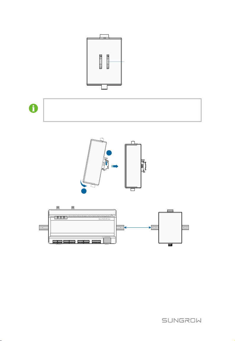
5.5 Installing Antenna
The sucker antenna base should be placed on a metal surface outside the container
to avoid impact on signal reception.
Antenna entry should be reserved on the container, and the entry hole size is 20mm.
Secure the sucker antenna base onto the surface outside the container, lead one
end (with the nut) of the antenna through the drilled hole, and fix it onto the
corresponding terminal of the Logger1000 clockwise, as shown in the figure below.
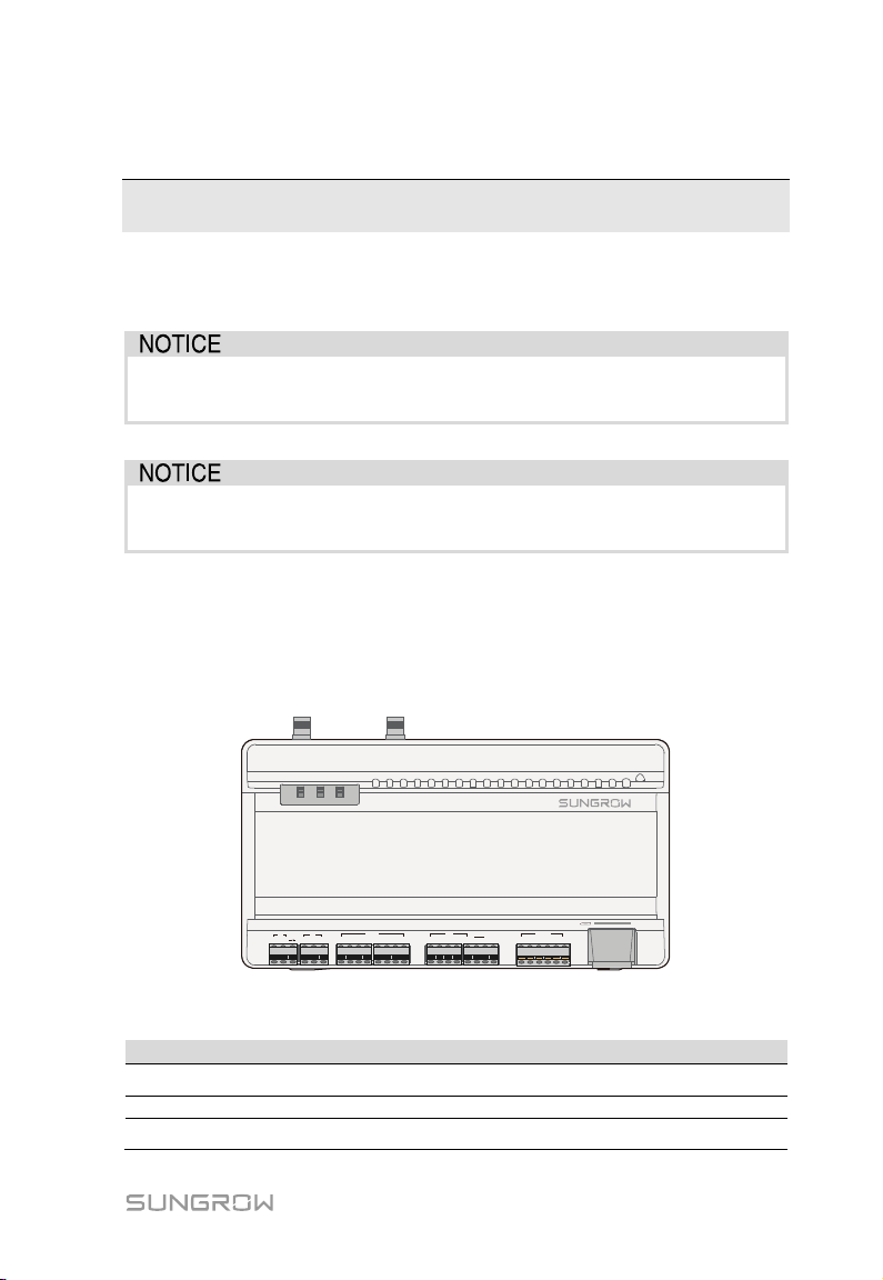
5.6 Installing Power Box
to onsite conditions.
Secure the power box via the buckles (as shown in the figure below) on the back of
it.
17
Page 24
5 Mechanical Installation User Manual
Buckle
The power box should be 200mm away from the Logger1000 to ensure
1
2
200mm
Step 1 Install and secure the power box guide rail at the appropriate location.
that the power cable from the power box can be connected to the
power input port of the Logger1000.
Step 2 Tilt the power box and hook the buckle into the guide rail. Press down the
power box until it snaps into place with an audible "Click" sound.
Step 3 The installation of the power box and Logger1000 is completed.
18
Page 25
1+ 1- 2+ 2-
AI/DI
3+ 4+3- 4-
1 2 3 4
DI DRM
0V
5 R C
A1 B1 A2 B2
RS485
A3 B3
RUN 4G WLAN
4G
RST
WLAN
ETH
24V
OUT
DI
+
-
24V
IN
+
-
Port
Function
Description
DI
Converters AI into DI
Switch for enabling the AI/DI function
6 Electrical Connection
6.1 Safety Instructions
Incorrect cable connection may cause device damage or even personal
injury.
All cables must be intact, well insulated, appropriately dimensioned, and
firmly connected.
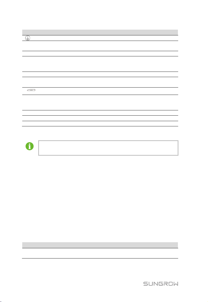
6.2 Port Introduction
External wiring terminals are located at the bottom of Logger1000, and the wiring
area is shown in the figure below.
Tab. 6-1 Port description
24V OUT 24V power output
24V IN 24V power input
19
Fig. 6-1 Wiring area
24V±5%, the max. output current: 0.5A
24V±3%
Page 26
6 Electrical Connection User Manual
Port
Function
Description
Grounding
Connecting protective grounding cable
Compatible with AI/DI
function
Default AI input sampling: 0-10V or
4-20mA
DI
Digital input
Digital signal input
DRM (Demand
function
0V
Digital reference point
-
RS485 communication
port
*
Can be connected to background master
router
WLAN
WLAN antenna
-
4G*
4G antenna
-
RST
Restart
Press it for 3s to restart
For the RS485 (A1B1~A3B3) ports, the communication distance should not
Cable
Type
Recommended cross-section
RS485 communication
cable
AI/DI
DRM
RS485
ETH Ethernet port
Response Modes)
SIM card slot Support of Micro-SIM card
Works together with the DI1~DI4 to
achieve the DRM function
Support of 3 inputs of RS485
via devices such as Ethernet switch and
Note: * Only the Logger1000A is equipped with the SIM card slot and the 4G
function.
exceed 1,000m.
6.3 Connection to PV Devices
Devices in the PV system that can be connected to the Logger1000 include the
inverter, Meteo Station, energy meter, etc.
6.3.1 Connection to Inverter
Connection to a single inverter
The RS485 port of SUNGROW inverter is RS485 terminal block or RJ45 port.
RS485 terminal block connection
Communication cable specification:
Shielded twisted pair 0.75mm2~1.5mm2
20
Page 27
User Manual 6 Electrical Connection
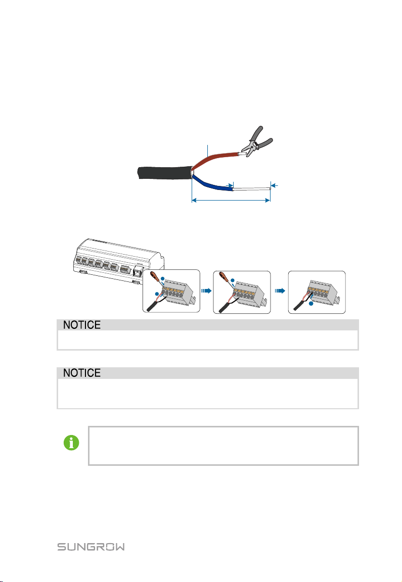
0.75 mm
2
1.5 mm
2
15mm
8~10mm
~
1
2
3
4
When a multi-core multi-strand copper wire cable is used, crimp an
Cable connection procedure:
Step 1 Lead the RS485 communication cable from the inverter to the wiring area of
Logger1000.
Step 2 Strip the cable jacket and insulation layer with a wire stripper by about
15mm and 8mm to 10mm respectively.
Step 3 Connect the stripped cable to the RS485 ports of the Logger1000, as shown
in the figure below.
RS485A is connected to port A while RS485B is connected to port B.
The RS485 communicati on cabl e must be t he shielded twisted pair with
the shielding layer single-point grounded.
appropriate euro style terminal at the communication cable head and
then connect it to the RS485 port of the Logger1000.
Step 4 Connect the Logger1000 to the inverter.
21
Page 28
6 Electrical Connection User Manual
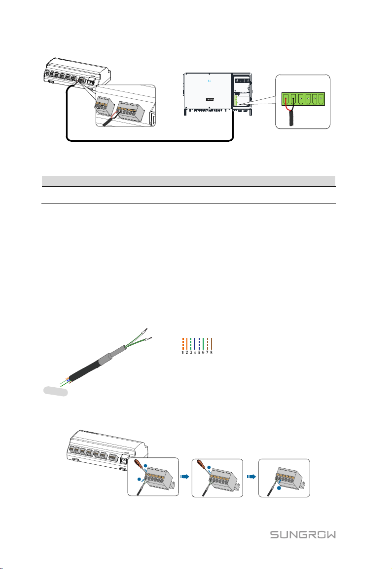
Logger1000
Inverter
A1 B1 PE A1 B1 PE
RS485
Cable
Type
Shielded twisted pair Ethernet cable
RS485+ A
RS485- B
1----8
Pin 3 and Pin 6 are used for
communication.
- Pin 3 to RS485- B
- Pin 6 to RS485+ A
Corresponding Relationship Between Cables
and Pins:
Pin 1: White-orange; Pin 2: Orange;
Pin 3: White-green; Pin 4: Blue;
Pin 5: White-blue; Pin 6: Green;
Pin 7: White-brown; Pin 8: Brown.
1
2
3
4
RJ45 port connection
Communication cable specification:
RS485 communication cable
Cable connection procedure:
Step 1 Lead the RS485 communication cable from the inverter to the wiring area of
Logger1000.
Step 2 Strip the insulation layer of the communication cable with an Ethernet wire
stripper, and lead the corresponding RS485A/B signal cables out. Insert cord
end terminals into signal cable RS485+ A and signal cable RS485- B, and
crimp them with a crimper. Cut off the redundant signal cable and warp it
with a heat-shrink tubing.
Step 3 If the communication cable is Shielded Ethernet cable, white-green wire 3 is
defined as RS485- B wire and the green wire 6 as RS485+ A wire.
Step 4 Connect the communication cable to the RS485 ports of the Logger1000, as
shown in the figure below.
Step 5 Connect the Logger1000 to the inverter.
22
Page 29
User Manual 6 Electrical Connection
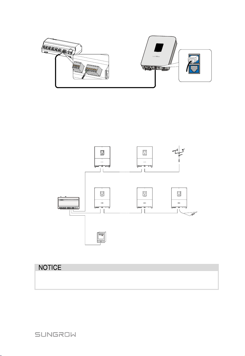
Logger1000
Inverter
...
...
Inverter Inverter Meteo station
Inverter Inverter Inverter
Logger1000
Energy meter
Connection to multiple devices
Multiple inverters are connected to the Logger1000 in the RS485 daisy chain
manner. If more than 15 inverters are connected on the RS485 bus, it is
recommended to connect a 120Ω terminal resistor in parallel on the RS485A and
RS485B lines at the head or tail end of the bus.
With an outdoor device connected to the Logger1000, it is recommended to
connect an SPD to protect the Logger1000 from lightning damage.
The Logger1000 allows for 3 inputs of RS485 buses and 30 devices at most.
23
Page 30
6 Electrical Connection User Manual
No.
Manufacture
Type
1
Sfere
PD194E/Z
2
Acrel
PZ96-E3
3
Acrel
DTSD1352
4
Janitza
UMG604
Logger1000
Energy meter
All devices on each RS485 bus support the same communication
Different device types must connect to different RS485 communication ports of
the Logger1000. For example, connect the transformer and inverter to different
RS485 communication ports of the Logger1000.
The addresses of devices on each RS485 bus must be different from one another
and within the address range set for the Logger1000 (address range of residential
inverters and string inverters manufactured by SUNGROW: 1-247; address range
of third-party devices: 1-255). Otherwise, communication error will occur.
Serial port parameters of each device on the RS485 bus should be consistent
with those of the Logger1000. The serial port parameters include baud rate, data
bit, stop bit, and check bit.
6.3.2 Connection to Energy Meter
It is recommended to use the energy meter whose communication protocol
complies with DL/T645-2007 protocol or Modbus RTU protocol. The recommended
energy meter types are as follows:
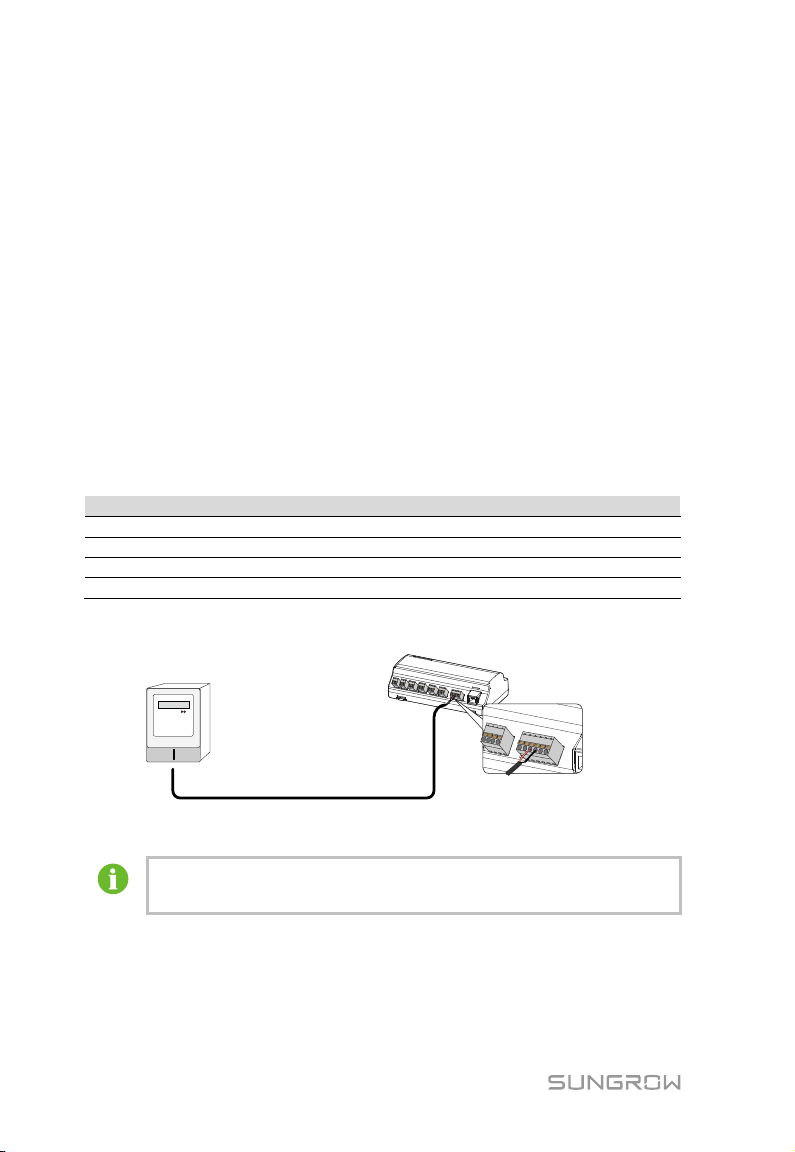
The following figure shows the connection between the Logger1000 and the energy
meter.
Connect the communication cable led from the energy meter to the RS485 port of
the Logger1000.
protocol.
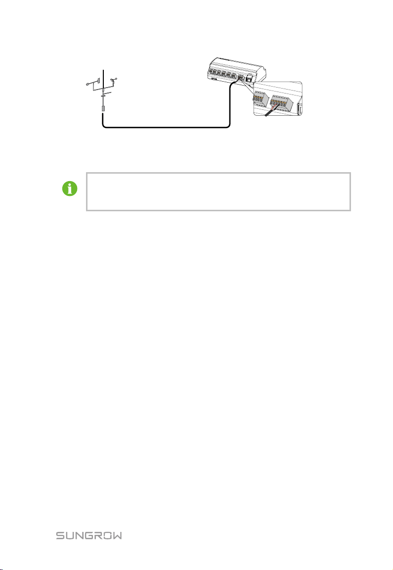
6.3.3 Connection to Meteo Station
The following figure shows the connection between the Logger1000 and the Meteo
Station.
24
Page 31
User Manual 6 Electrical Connection
Logger1000
Meteo Station
If multiple inverters are connected to the Logger1000 together with the
Connect the communication cable led from the Meteo Station to the RS485 port of
the Logger1000.
Meteo Station, the Meteo Station should be connected on the very end
of the daisy chain.
6.4 Connection to Background
The Logger1000 can be connected to the background of the PV system via the
network port, and the communication protocol is standard Modbus TCP or IEC104.
As a salve device, the Logger1000 can be accessed by multiple backgrounds and
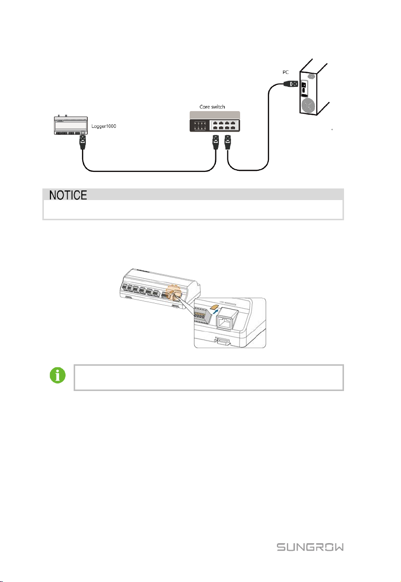
communicate by using the standard protocol. The following figure shows the
connection between the Logger1000 and the background.
The Logger1000 can be connected to multiple monitoring background systems via
the Ethernet switch or router, or it may be connected to the single monitoring
background system via the network cable.
For example, the Logger1000 is connected to the background system via the
Ethernet switch, and the wiring steps are as follows:
Step 1 Prepare an Ethernet cable of suitable length.
Step 2 Insert one end of the cable into the port of the Ethernet switch and the other
end to the "ETH" port of the Logger1000.
Step 3 Set IP address of the ETH port to be within the same network segment as
that of the background monitoring system.
25
Page 32
6 Electrical Connection User Manual
Fig. 6-2 Connection to PV background system
Default IP of the "ETH": IP12.12.12.12.
6.5 Connection to Micro-SIM
Support of hot plug of Micro-SIM.
6.6 Connection to Power Box
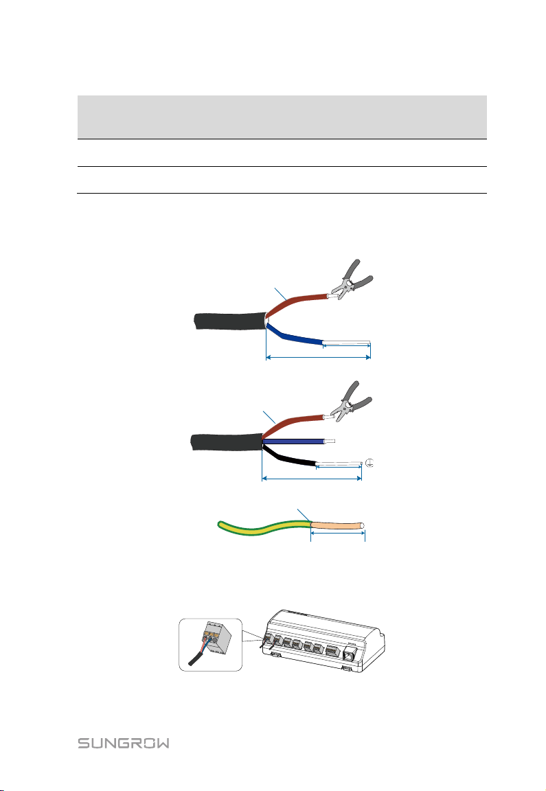
The Logger1000 supports DC24V power supply. Prepare two-core DC cable,
three-core AC cable, and grounding cable before wiring. Power cable specifications
are shown in the table below.
26
Page 33
User Manual 6 Electrical Connection
Length of cable
to be
stripped off
Length of
insulation to be
stripped off
DC cable, AC
cable
Grounding
cable
1mm
2
~
1.5 mm
2
A
A:15mm
B:8mm~10mm
B
DC cable
AC cable
A
A:15mm
B:8mm~10mm
B
1mm
2
~
1.5 mm
2
L
N
A
1mm
2
~
1.5mm
2
A:8mm~10mm
Grounding cable
Tab. 6-2 Power cable specification
Cable
Recommended
cross-section
jacket
1mm2~1.5mm2 15mm 8mm~10mm
1mm2~1.5mm2 8mm~10mm -
Power cable wiring steps are as follows:
Step 1 Strip the cable jackets and insulation layers of the DC cable, AC cable, and
grounding cable with a wire stripper by appropriate length.
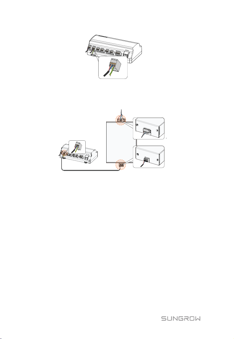
Step 2 Insert the stripped DC cable into the "24V IN" and "24V OUT" ports of the
Logger1000. Connect the DC cable led from the "24V OUT" port of the
Logger1000 to other devices that need 24V DC power supply.
Step 3 Connect the stripped grounding cable to the corresponding port of the
Logger1000.
27
Page 34
6 Electrical Connection User Manual
Logger1000 Power box
DC 24V OUT
AC (100~277V)
Step 4 Connect the DC cable led from the "24V IN" port of the Logger1000 to the
"DC 24V OUT" port of the power box. Connect the stripped AC cable to the
"AC (100~277V)" port of the power box, and connect the other end of the AC
cable to the 220V AC power.
6.7 Cable Routing Requirements
Cables used in the system generally include power cables and communication
cables.
The communication cable needs to be routed away from the power cable, and the
cables need to form a right angle at the intersection. The communication cable
needs to be as short as possible and keeps a distance from the power cable.
Power cables and communication cables should be routed in different cable
trenches to avoid long-distance parallel cable routing of power cables and other
cables, thereby reducing electromagnetic interference due to output voltage
transient.
The distance between the power cable and communication cable should be greater
than 200mm. When the cables meet with each other, the cross angle should be 90°,
and the distance can be reduced accordingly.
The following table shows the recommended minimum distances between parallel
28
Page 35

User Manual 6 Electrical Connection
Parallel cable length (m)
Min. distance (m)
200
0.3
300
0.5
500
1.2
shielded communication cables and power cables.
The communication cables should be routed as closely to the ground surface or
supports (such as support beam, steel channel, or metal rail) as possible.
29
Page 36
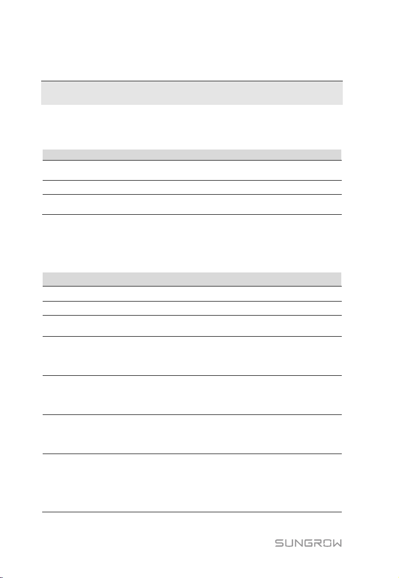
No.
Inspection item
Result
All cables are intact, well-insulated, and appropriately
dimensioned
The polarity of the power supply cable is correct. The grounding
cable is reliably grounded
Connect the debugging PC to the "ETH" port of the Logger1000 via
browser.
Make sure the communication cable connecting the device and
breaker of the inverter to ensure the inverter is supplied with
power.
Set serial port parameters by referring to the "RS485" chapter,
bit.
Set the devices connected to the Logger1000 through the device
devices of other types, connect them to the Logger1000 by
referring to "8.8.1 Device List". For the devices of other types, the
7 Commissioning
7.1 Inspection before Commissioning
1
2 All cables are connected correctly and firmly
3
□
□
□
7.2 Commissioning Steps
Tab. 7-1 Commissioning Steps
No. Step Result
1 Inspection before commissioning
2 Power on the Logger1000.
3 Check whether the indicators of Logger1000 normally flash.
the network cable (default IP address of "ETH": 12.12.12.12).
4
Log in the Web at 12.12.12.12 through the IE, Safari or Chrome
the Logger1000 is firmly in place, and connect the DC circuit
5
including the baud rate, check bit, data bit, and stop bit.
6
The default setting is 9600bps, 8 data bit, 2 stop bit, and no check
□
□
□
□
□
□
management function. If the device connected for the first time is
SUNGROW string inverter, use "
7
the device whose address will be automatically allocated. For
30
8.8.1 Device List" function to search
□
Page 37
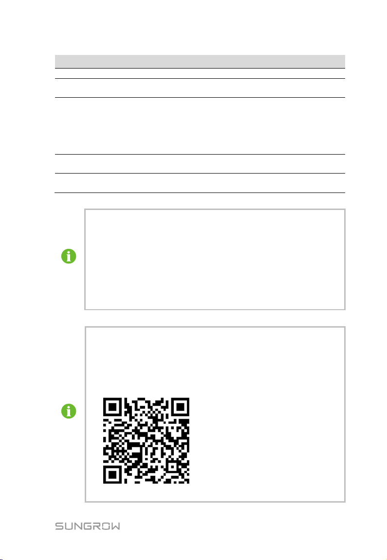
User Manual 7 Commissioning
communication address needs to be preset.
Enable the DHCP service of the router, so that the Logger1000
automatically obtains the IP address via the DHCP function.
Set the iSolarCloud address if data needs to be uploaded to cloud
s "China Station". Users in
the "Europe Station", and users in other regions access the
"International station".
Check the data of SUNGROW string inverter for correctness on the
real-time information interface.
Create new plant via the iSolarCloud APP and check the
iSolarCloud data for correctness.
Addresses of the device connected to the same communication port
Use the iSolarCloud APP to create a new plant. Users can directly scan
dance of iSolarCloud APP. Scan the bottom QR Code to view or
No. Step Result
8
server.
The default iSolarCloud station i
9
mainland China access the "China Station", users in Europe access
10
11
□
□
□
□
The auto search function is available for SUNGROW string inverters
whose addresses are automatically allocated.
Devices of other types, such as energy meter and transformer, can be
connected to Logger1000 via the adding device function.
should be different from each other.
Save the settings after operation, and otherwise the settings will not
take effect.
the QR code on the front label of the Logger1000 or manually input the
S/N to add communication equipment. For details, refer to the Quick
Gui
obtain the Quick Guidance of iSolarCloud APP.
31
Page 38
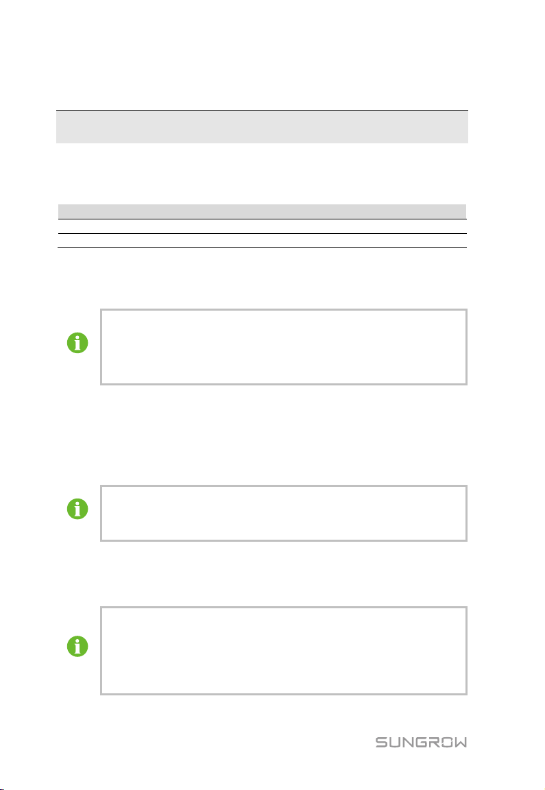
Item
Parameter
Browser
IE11 or later, Chrome65 or later, and Safari11 or later
Min. resolution
1024*768
The Web interfaces provided in this document are for reference only,
the permission to set and modify parameters of the Logger1000 and
8 Web Interface
8.1 Running Requirements
8.2 Login Steps
and the actual ones may differ.
Users of different types have different permissions. In the following,
description is given by using the O&M permission as an example.
Users can log into the Logger1000 via the Ethernet or WiFi (recommended).
8.2.1 WiFi Login
Step 1 Open the wireless network settings of the PC, search for the wireless network
"SG-A1234567890" of the Logger1000, and connect the PC to the wireless
network of the Logger1000 (without password).
"SG-A1234567890" is just used as an example. For actual wireless
network, refer to the S/N on the label attached to the front side of the
Logger1000.
Step 2 Enter the IP address 11.11 .11.1 of the Logger1000 in the PC address bar to
enter the general user login interface.
Step 3 Click the button "Login" in the upper right corner, enter the default password
"pw 1111", and click "Login", to enter the O&M user interface.
User types include "general user" and "O&M user".
The general user can view basic information, real-time fault, and
device monitoring information of the Logger1000.
In addition to all permissions of the general user, the O&M user has
32
Page 39
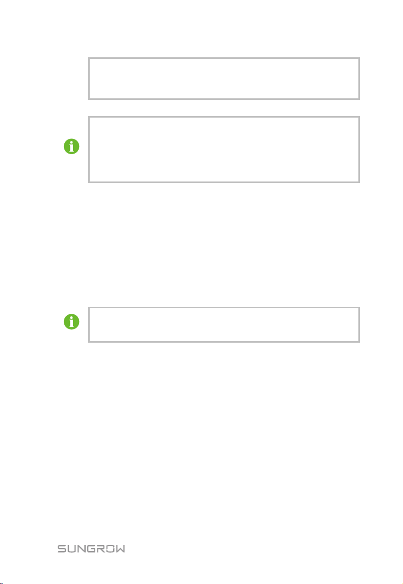
User Manual 8 Web Interface
devices connected to the Logger1000.
In the following, description is given by using the O&M permission as an
example.
After login for the first time, it is recommended to change the password
as soon as possible. Click "O&M user" -> "Modify password" to change
the password.
With the login password forgot en, contact SUNGROW and provide the
device S/N as well as system time, to get the password.
8.2.2 Ethernet Login
Step 1 The IP address of the PC connected to the Logger1000 is the same as that of
the Logger1000. The IP address is 12.12.12.X. For example, the IP address of
the PC can be set to 12.12.12.125, and the subnet mask is 255.255.255.0.
Step 2 Connect the Logger1000 to the PC via the Ethernet.
Step 3 Enter the IP address 12.12.12.12 of the Logger1000 in the PC address bar to
enter the general user login interface.
Step 4 Click the button "Login" in the upper right corner, enter the default password
"pw 1111", and click "Login", to enter the O&M user interface.
User types include "general user" and "O&M user".
Users of different types have different permissions.
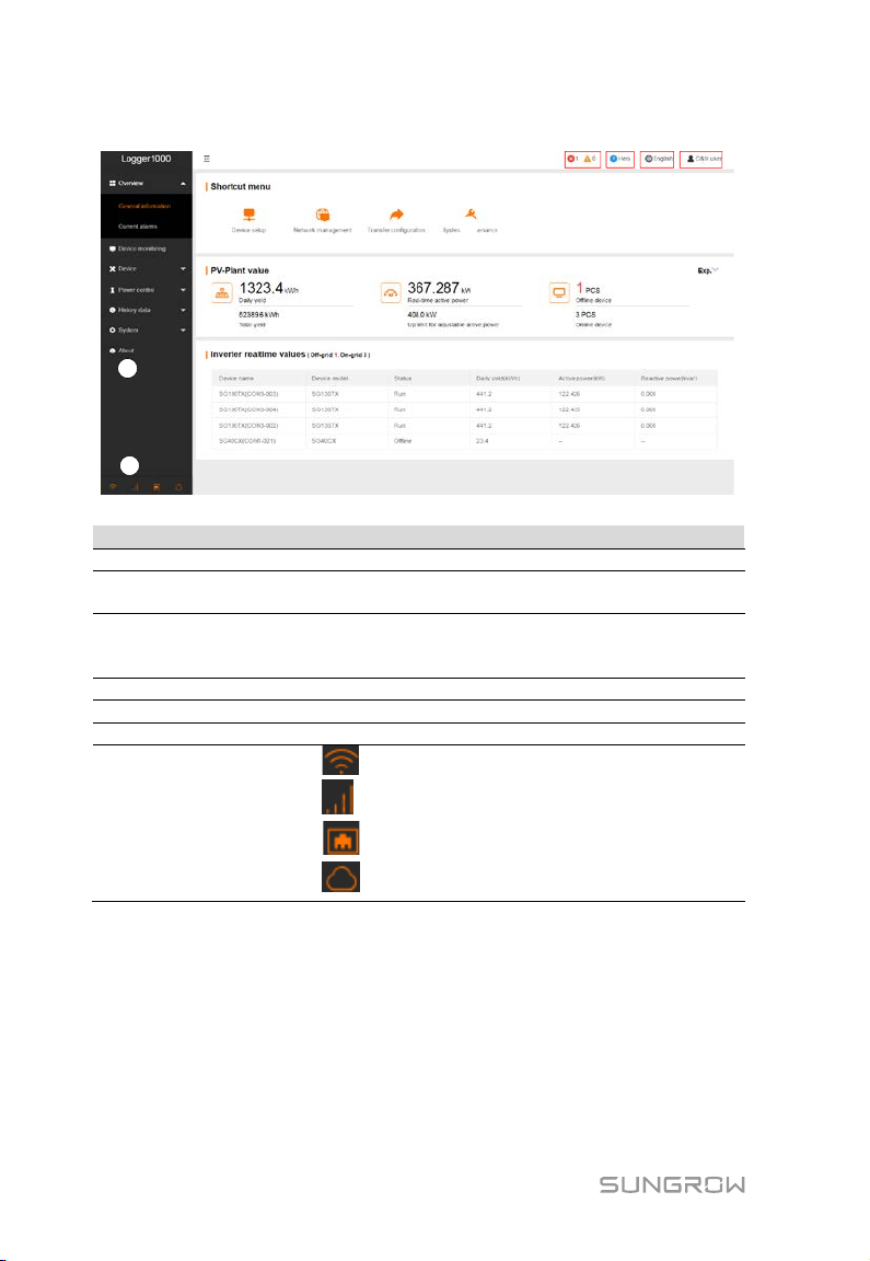
8.3 Web Main Interface
When the "O&M user" logs into the Web for the first time, the "Help" window pops
up. Follow the prompts to perform operations such as time synchronization, device
connection, and forwarding configuration.
The Web main interface is as follows:
33
Page 40
8 Web Interface User Manual
A
B
C
G
D E F
Item
Designation
Description
A
Navigation menu
Display main function modules of the Web
Function display
area
Display the current alarm level and alarm number. Users
D
Help
Display the basic configuration steps of the Logger1000
E
Language menu
Click the button to select the desired language
F
User
Display the current login user
B
C Alarm icon
G Information icon
Display the current interface
can click the icons to enter the corresponding alarm
interface
: WiFi connection
:Wireless connection
:Ethernet Connection
:Cloud access
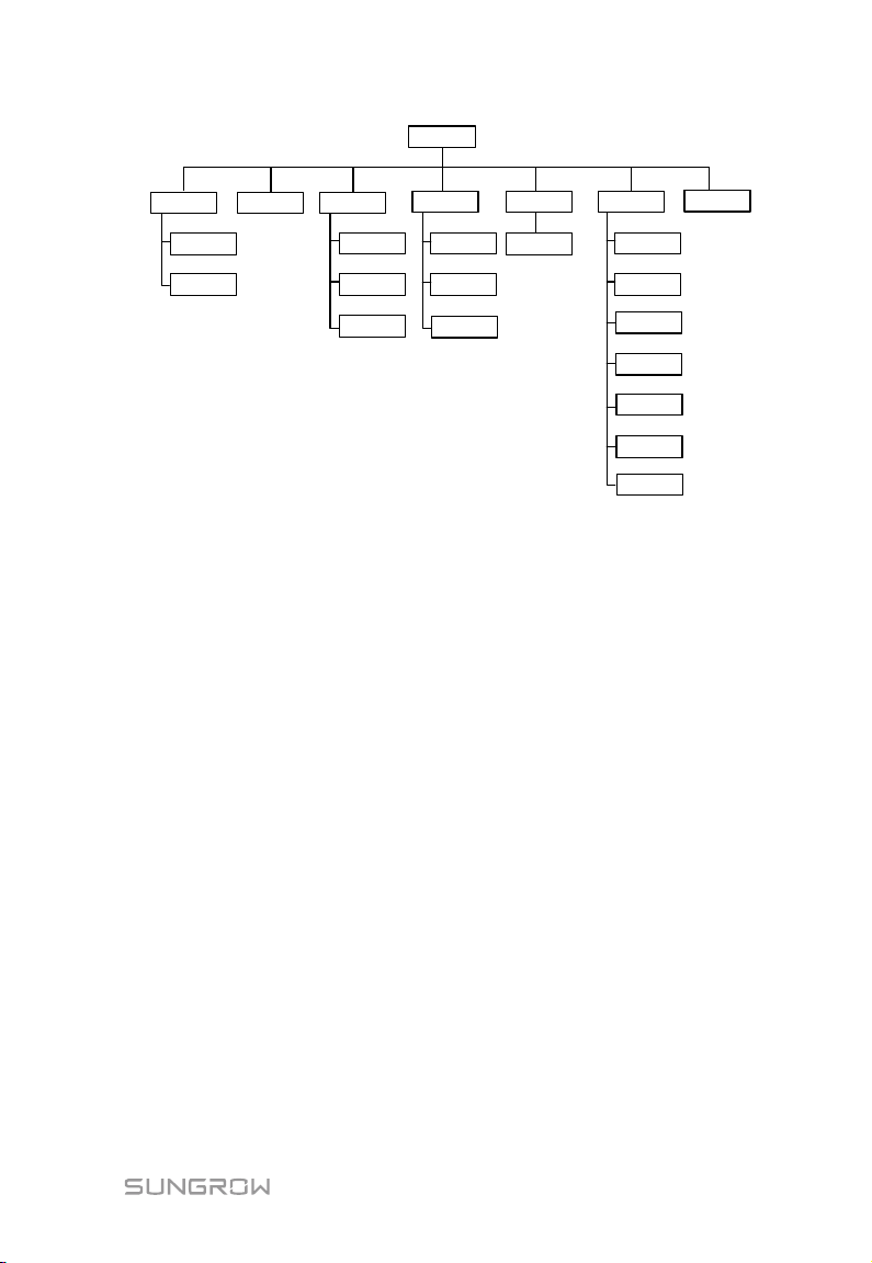
8.4 Web Menu
The Web has seven main function modules: "Overview", "Device monitoring",
"Device", "Power Control", "History Data", "System", and "About".
The permissions of the O&M users are as follows:
34
Page 41
Main menu
Overview
Device
monitoring
Device
Power control
General
information
Active power
Reactive power
Device list
Firmware update
Inverter log
Transfer
configuration
Emergency
button
Interface
Current alarms
History data
Operation
logbook
System
Run-info
System
maintenance
System time
About
Remote
maintenance
Message export
User Manual 8 Web Interface
8.5 Operation Procedure
Perform the following operations before logging into the Logger1000 Web for the
first time.
Step 1 Complete the electrical connections.
Ensure that the Logger1000 has been correctly connected to other devices. Refer to
the chapter "6 Electrical Connection".
Step 2 Configure serial ports of the Logger1000.
After logging into the Web, first configure the serial ports of the Logger1000, to
ensure that the Logger1000 can normally communicate with upstream devices.
Refer to the chapter “8.10.7 Interface”.
Step 3 Calibrate the system time.
Check whether the current system time is correct, and perform manual time
synchronization or automatic time synchronization when necessary. Refer to the
chapter "8.10.5 System Time".
Step 4 Automatically search the device.
Devices that can be automatically searched, such as SUNGROW string inverter, can
be added via the auto search function with addresses allocated automatically. Refer
to the chapter “8.8.1 Device List”.
Step 5 Add the device. Refer to the chapter “8.8.1 Device List”.
Step 6 Configure forwarding service.
35
Page 42
8 Web Interface User Manual
After all devices have been added, configure the forwarding service of the
Logger1000, to ensure that the Logger1000 can forward the data to upstream
devices. Refer to the chapter "8.10.6 Forwarding Configuration".
8.6 Overview
8.6.1 General Information
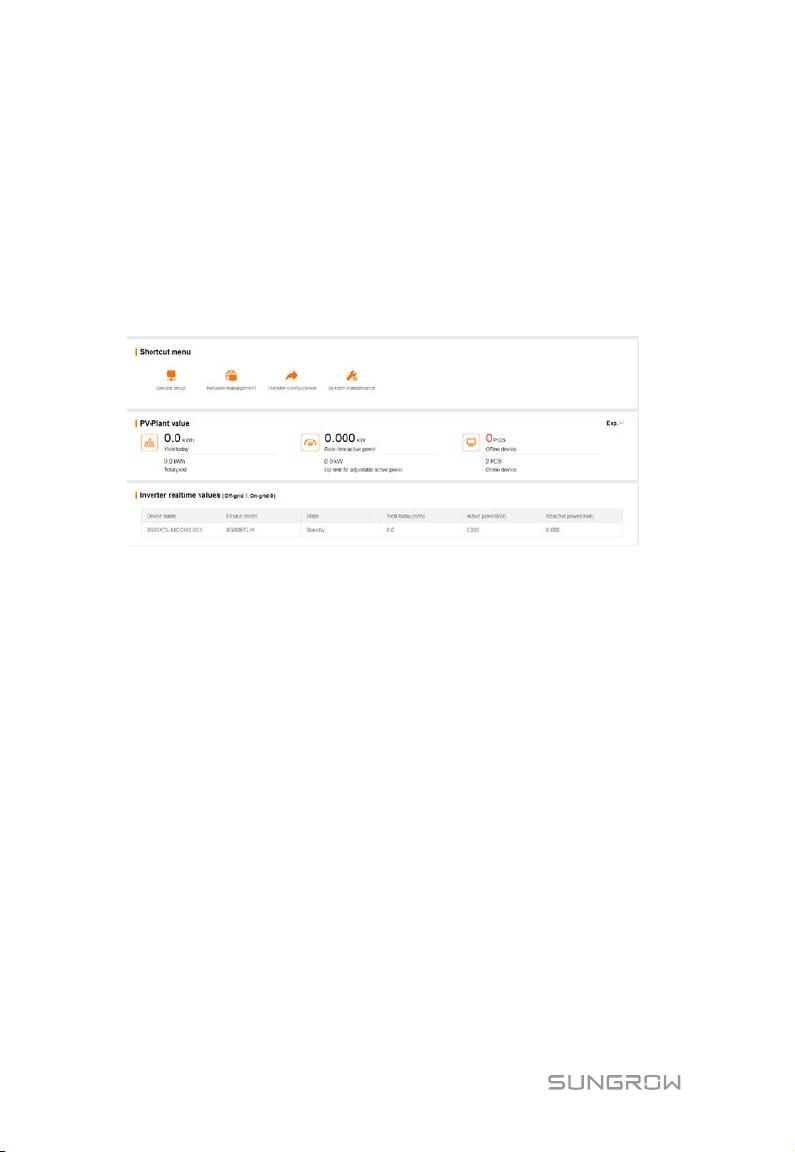
Click "Overview" -> "General information" to enter the corresponding interface.
Shortcut menu
Device setup: support of auto search and add device functions. Click the menu to
add, delete, modify, and view the device or perform auto search operation to search
the device to which address will be automatically allocated. Refer to the chapter
“8.8.1 Device List”.
Network management: set Ethernet parameters. Refer to the chapter “8.10.7
Interface”.
Transfer configuration: transfer the data connected by the system to the
background. Refer to the chapter "8.10.6 Forwarding Configuration".
System maintenance: support of operations such as system upgrade, log export,
and rebooting. Refer to the chapter "8.10.2 System Maintenance”.
PV-plant value
Information such as today yield, total yield, real-time active power, and number of
offline devices can be viewed.
Click the button "Exp." to view more information.
36
Page 43

User Manual 8 Web Interface
Inverter realtime values
Information on the inverter such as state, daily yield, active power, and reactive can
be viewed.
8.6.2 Current Alarms
Click "Overview" -> "Current alarms" to view the device fault information.
Information such as device name, alarm name, alarm type, alarm time, fault code,
and fault ID can be viewed.
8.7 Device Monitoring
Click "Device Monitoring" to enter the corresponding interface.
Device information such as real-time values, DC data, initial parameter, protection
parameter, general parameter, device instruction and device information can be
viewed on this interface.
8.7.1 RealTime Values
Realtime information such as power generation, device state, and active power can
be viewed on this interface.
Step 1 Click "Device Monitoring" -> "Realtime values" to view the corresponding
information.
Step 2 Click the button “ ” to select the device type.
8.7.2 DC Data
Click "Device Monitoring" -> "DC data" to view the corresponding information.
On this interface, voltage and current information of multiple inputs of MPPTs and
strings can be viewed.
8.7.3 Initial Parameter
Click "Device monitoring" -> "Initial parameter" to enter the corresponding interface
and set initial parameters.
Initial parameters can be set in two manners: single setting and batch setting.
Single setting
Step 1 Select the desired country (region) and grid type.
37
Page 44

8 Web Interface User Manual
Step 2 Click "Setting" to set initial parameters for the single device.
Batch setting:
Step 1 Select the desired country (region) and grid type.
Step 2 Click "Configure synchronization".
Step 3 Select the desired devices in the pop-up device list, and click "Save" to
achieve batch setting.
8.7.4 Protection Parameter
Click "Device monitoring" -> "Protection parameter" to enter the corresponding
interface and set protection parameters.
Protection parameters can be set in two manners: single setting and batch setting.
For specific setting method, refer to “8.7.3 Initial Parameter".
8.7.5 General Parameter
Step 1 Click "Device monitoring" -> "General parameters" to enter the
corresponding interface and set general parameters.
Step 2 Select "Read-back", set register address, register number, and address type,
and click the button "Read-back", to read the current value of the device.
Step 3 Select "Setting", set register address, data type, and set value, and click the
button "Save", to set device parameters.
8.7.6 Device Instruction
Click "Device monitoring" -> "Device instruction" to enter the corresponding
interface.
On this interface, users can boot/shutdown the device or reset all settings.
Device instruction can be set in two manners: single setting and batch setting. Take
the boot operation as an example for explanation.
Single setting
Step 1 Select a device, click “boot”, and a dialog box pops up.
Step 2 Click “Yes” to start a single device.
Batch setting
Step 1 Select a device, click “boot”, and a dialog box pops up.
Step 2 Click "Configure synchronization".
38
Page 45
User Manual 8 Web Interface
t the SN do not support the automatic search function
Step 3 Select the desired devices in the pop-up device list, and click "Save" to
achieve batch setting.
Step 4 Click “Confirm” on the pop-up dialog box.
8.7.7 Device Information
Click "Device Monitoring" -> "Device Information" to view the corresponding
information.
Parameter information such as device S/N, device model, and rated active power
can be viewed.
8.8 Device Maintenance
8.8.1 Device List
The function module "Device list" is used for managing devices connected to the
Logger1000 and configuring addresses for these devices. Devices can be
automatically searched and added.
Auto search
The "Auto search" function is used for SUNGROW string inverter to which addresses
will be automatically allocated.
Step 1 Click "Device" -> "Device list" to enter the corresponding interface.
Step 2 Click the button "Auto search", and the corresponding window pops up.
Select an interface type, and click "Search".
Step 3 After that, corresponding devices will be displayed.
Inverters withou
and device adding function.
Automatic address allocation pops up only when there is an actual
address confrontation.
Export
Step 1 Click "Device" -> "Device list" to enter the corresponding interface.
Step 2 Click the button to export the device list.
Import
Step 1 Click "Device" -> "Device list" to enter the corresponding interface.
39
Page 46
8 Web Interface User Manual
The "Device Name" is named in the form device model (port
Step 2 Click the button to export the device list.
Step 3 After the device list is exported, the user can modify device names in batch.
Step 4 After the modification is completed, save the device list file in the .csv format.
Step 5 Click the button to import the .csv file into the Web.
Add device
Step 1 Click "Device" -> "Device list" to enter the corresponding interface.
Step 2 Click "Add device", select a device type in the pop-up window, and fill in the
information required.
Edit device
Step 1 Click "Device" -> "Device list" to enter the corresponding interface.
Step 2 Click the button in the operation bar, to modify the name of the device
connected to the Logger1000 and other parameters.
Step 3 Click "Save".
number-communication address).
Take SG36KTL-M (COM1-7) as an example. SG36KTL-M is device type,
COM1 is the communication port, and 7 is the communication address.
Delete device
After a device is deleted on site, the user can delete the device from the device list,
to keep device consistency.
Step 1 Click "Device" -> "Device list" to enter the corresponding interface.
Step 2 Select the device to be deleted, click the button "Delete".
Step 3 Click "Confirm" in the pop-up window, to delete the device.
8.8.2 Firmware Update
The firmware update function is used to upgrade the SUNGROW residential inverter
and string inverter.
Step 1 Click "Device" -> "Firmware update" to enter the corresponding interface.
Step 2 Click the button "Select a firmware file".Select an upgrading file and import it
to the system. Matching inverters will be detected.
Step 3 Select the device to be upgraded, and click “Upgrade”.
40
Page 47
User Manual 8 Web Interface
Step 4 Complete firmware update to view current version, target version, start time,
end time and other information.
The firmware file should be in the ".sgu" format.
8.8.3 Inverter Log
Step 1 Click "Device" -> "Inverter log" to enter the corresponding interface.
Step 2 Select the device running information, and click the button to view the
export progress.
Step 3 Click "Save" to store the exported log in the local.
Step 4 Click "Cancel" and then "Confirm" on the pop-up window, to cancel the
current operation.
8.9 History Data
Click "History data" -> "Operation logbook" to enter the corresponding interface.
On this interface, users can view history information.
8.10 System
8.10.1 Running Information
Click "System" -> "Run-info" to enter the corresponding interface.
Information such as mobile network signal strength, WiFi, AI voltage, DI status can
be viewed.
8.10.2 System Maintenance
System upgrade
Users can upgrade Logger1000 on the Web interface.
Step 1 Click "System" -> "System maintenance" to enter the corresponding
interface.
Step 2 Click "System upgrade", select the upgrade file, and export it to the system.
Step 3 Click "Upgrade" on the pop-up version information window. The system
enters upgrade state.
41
Page 48
8 Web Interface User Manual
Remote maintenance switch state
Description
Not allow for remote maintenance on the
Logger1000
Enable
Allow for remote maintenance on the
The upgrade file should be in the ".zip" format.
Log export
Step 1 Click "System" -> "System maintenance" to enter the corresponding
interface.
Step 2 Click the button "Log export" to enter the corresponding interface.
Step 3 Select the type of logs to be exported, and click "Confirm".
Rebooting
Step 1 Click "System" -> "System maintenance" to enter the corresponding
interface.
Step 2 Click "Rebooting" to enter the corresponding interface.
Step 3 A warning window will pop up, and click "Confirm" to continue the rebooting
operation.
Reset all setting
Step 1 Click "System" -> "System maintenance" to enter the corresponding
interface.
Step 2 Click "Reset all settings" to enter the corresponding interface.
Step 3 A warning window will pop up, and click "Confirm" to continue the reset all
settings operation.
Restoring the factory settings refers to restoring all modified settings to the factory
state and will not clear the data.
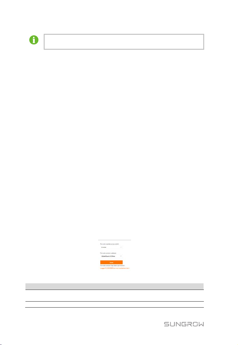
8.10.3 Remote Maintenance
Click "System" -> "Remote maintenance" to enter the corresponding interface.
Tab. 8-1 Parameter description
Disabled
42
Page 49
User Manual 8 Web Interface
Remote maintenance switch state
Description
Logger1000
Parameter
Description
Range
Serial port: COM1, COM2, COM3
Network port: ETH, WiFi, 4G
Export the message recorded
during the set time
In case the remote maintenance switch is in the "Enable" state, the remote service
address needs to be set. Users in mainland China select "iSolarCloud of China", users
in Europe select "iSolarCloud of Europe", and users in other regions select the
"iSolarCloud of International".
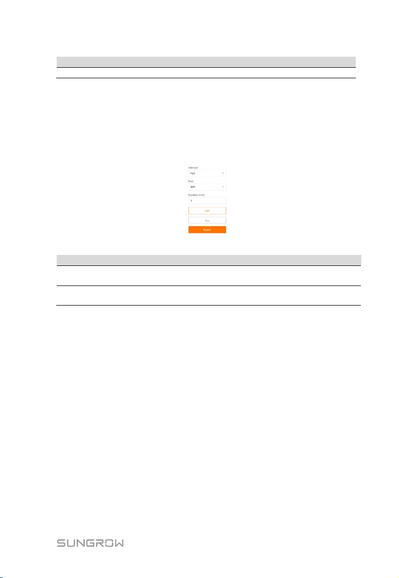
8.10.4 Message Export
Step 1 Click "System" -> "Message export" to enter the corresponding interface.
Tab. 8-2 Parameter description
Port -
Duration
Step 2 Set parameters, including interface, serial port, and duration, and click "Start"
to start recording message. The recording automatically stops when the set
time reaches, or the user may manually click the button "Stop" to stop
recoding message.
Step 3 Click "Export" to export the message.
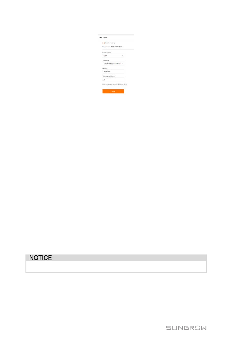
8.10.5 System Time
Click the "System time" to check whether the current system time is correct,
synchronize the system time, and enable/disable "Inverter timing".
Click "System" -> "System time" to enter the corresponding interface.
43
1min ~ 10min
Page 50
8 Web Interface User Manual
Method of setting system time:
1. When the option "Inverter timing" is selected, device time will be
synchronized with the time of Logger1000.
2. When the clock source is set to "User define", user can manually set the
current system time and time zone in the following two manners:
Select "Use PC time" to synchronize the time of the Logger1000 with the time of
the PC.
Click the "Time zone" pull-down-list and select the local time zone. Enter the
"Date" and "Time" and click "Save" to manually set the time of the Logger1000.
It is recommended to select "User define" during debugging.
3. When the clock source is set to "NTP", time of all devices can be synchronized.
Click the "Time zone" pull-down-list and select the local time zone. Fill in the
domain, set the time interval, and click "Save". In this way, the time of the
Logger1000 is synchronized with the time of the server.
4. The clock source is set to "IEC104". In this way, the Logger1000 and the
background must use the IEC104 communication protocol, and otherwise,
this manner is invalid.
5. The clock source is set to "iSolarCloud".
6. The clock source is set to "MODBUS-TCP".
It is recommended that the top priority should be given to the IEC104 and then the
iSolarCloud.
Set the system time when using the Logger1000 for the first time.
8.10.6 Forwarding Configuration
The Logger1000 supports data forwarding to the background, before which
forwarding service configuration needs to be performed. The Logger1000 includes 4
kinds of forwarding services: iSolarCloud, IEC104, MODBUS, and third-party portal.
44
Page 51
User Manual 8 Web Interface
The default iSolarCloud station is "iSolarCloud of China". Users in
mainland China select "iSolarCloud of China", users in Europe select
loud of Europe", and users in other regions select the
Data Type
Description
YC
Telemetry
YX
Telesignalling
YM
Remote pulse
YK
Remote control
Click "System" -> "Transfer configuration" to enter the corresponding interface.
iSolarCloud
"iSolarC
"iSolarCloud of International".
Step 1 Click "System" -> "Transfer configuration" to enter the corresponding
interface.
Step 2 Click the button to modify the forwarding configuration information of
iSolarCloud.
IEC104
Configure the IEC104 forwarding service for the Logger1000 on this interface.
Click "System" -> "Transfer configuration" -> "IEC104" to enter the corresponding
interface.
The local port is 2404.
White list setting
When the option "Enable the white list or not" is not selected, and the default IP
address is "0.0.0.0", any background devices with valid IP address can access the
Logger1000.
When the option "Enable the white list or not" is selected, and specified IP address is
entered, only the device with the specified IP address can access the Logger1000.
Edit IEC104 forwarding point table
Step 1 Click "Export of configuration tools" to export the IEC104 forwarding point
table.
Step 2 Open the sheet "Introduce" of the IEC104 forwarding point table, where data
of five types (telemetry, telesignalling, remote pulse, remote control, and
remote regulating) are included.
Tab. 8-3 Introduce tab parameters
45
Page 52

8 Web Interface User Manual
Data Type
Description
YT
Remote regulating
Data Type
YX
YC
YM
YK
YT
Bngr Addr
1
16385
15221
15271
15000
Data
Type
YC 1 Y N 1000 W P
YC 2 Y N 1000
Var
Q
YX 3 Y Y 1
NA
On-grid
YX 4 Y N 1
NA
Off-grid
YM 5 Y N 1
kWh
E-Daily
YK 6 Y N 1
NA
Power On / Off
YT 7 Y N 1
kW
P-Set
YT 8 Y N 1
Var
Q-Set
Parameter
Value
Description
Data Type
-
Data type
Data ID
-
Data type
Data is uploaded to the background via the IEC104
communication protocol
N
Data is not uploaded to the background
Y
Negate, 0 is 1, and 1 is 0, available for telesignalling only
N
No negate, 0 is 0 and 1 is 1
Coefficient, available for telemetry, remote pulse, and
remote regulating only
Unit, available for telemetry, remote pulse, and remote
NA indicates no unit
Data Name
-
Data name in multiple languages
Step 3 Open the sheet "Cfg Para" of the IEC104 forwarding point table to view and
set the addresses of the five types of data. The addresses shown in the
following table are default ones and can be modified according to actual
situation.
Tab. 8-4 Cfg Para tab parameters
Step 4 Open the sheets such as inverter, energy meter, Meteo Station, and
Logger1000, to set corresponding measuring point data.
DataID State Invert Coefficient Uint Data Name
State*
Invert*
Coefficient* -
Uint -
Y
regulating only
Note: * indicates that the parameters should be set according to onsite conditions.
Step 5 Open the sheet "Device List" of the IEC104 forwarding point table to sort the
devices.
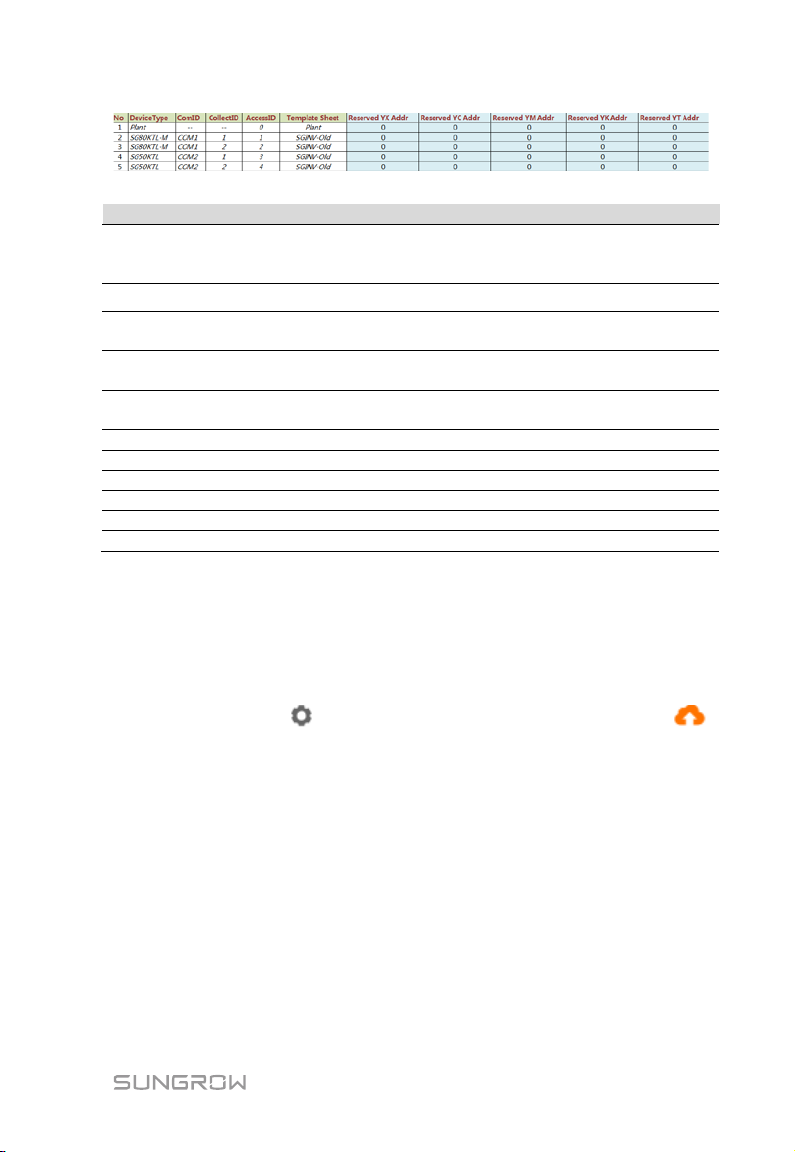
46
Page 53
User Manual 8 Web Interface
Parameter
Description
Sort devices, and only support moving the whole line for the
line
Device type
Number of COM port to which device connected, corresponding
to the port data of the "Device list" on the Web interface
Collect device Modbus address, corresponding to communication
address of the "Device list" on the Web interface
Background access address, corresponding to the forwarding
address of the "Device list" on the Web interface
Template Sheet
Keep consistent with the that in the device sheet
Reserved YX Addr
Reserved telesignalling address
Reserved YC Addr
Reserved telemetry address
Reserved YM Addr
Reserved remote pulse address
Reserved YK Addr
Reserved remote control address
Reserved YT Addr
Reserved remote regulating address
No.
Device Type
Com ID*
Collect ID*
Access ID*
device type corresponds one-to-one to its parameters in the same
Note: Export the excel from the "Device list" interface and copy the data in the
exported excel.
Import IEC104 forwarding point table
Step 1 After editing the IEC104 forwarding point table, click "Export" -> "IEC104
CFG", so that a prompt window pops up, and then convert the excel file into
xml file. The xml file and the excel file are at the same path.
Step 2 Click the button on the operation bar, and then click the button
on the pop-up window, to import the xml file.
MODBUS
Configure the MODBU forwarding service for the Logger1000 on this interface.
Step 1 Click "System" -> "Transfer configuration" -> "MODBUS" to enter the
corresponding interface.
Step 2 For the white list setting, refer to the description in "IEC104".
Third-party portal
Configure the third-party cloud forwarding service for the Logger1000 on this
interface.
47
Page 54
8 Web Interface User Manual
When the Logger1000 is connected to a device via the serial port, the
as those set for the connected device, so as to ensure normal
Ethernet and the WiFi STA are at different network segment. Otherwise,
Step 1 Click "System" -> "Transfer configuration" -> "Third-party portal" to enter the
corresponding interface.
Step 2 Turn on the switch.
Step 3 Click the button on the operation bar, so that an advanced setting
window will pop up.
Step 4 Modify the configuration information and click "Save".
8.10.7 Interface
Set ports of the Logger1000 on the interface.
RS485
Step 1 Click "System" -> "Interface" -> "RS485" to enter the corresponding interface.
Step 2 Click to modify baud rate, parity bit, and stop bit.
Step 3 Click to save the information.
baud rate, parity bit, and stop bit of the serial port should be the same
communication between the Logger1000 and the connected device.
The baud rate is 9,600bps, stop bit is 1, and there is no parity bit by
default.
Ethernet
Perform Ethernet settings on this interface.
Step 1 Click "System" -> "Interface" -> "Ethernet" to enter the corresponding
interface.
Step 2 If auto IP allocation is , it is recommended to obtain the current IP
address of the ETH port by connecting the WiFi module and logging into
11.11.11.1.
Step 3 If the parameter "Automatically obtain IP settings (DHCP)" is set to ,
fill in the information such as the IP address, subnet mask, and default
gateway, and click the button
to save the operation.
The default IP address of the ETH port is 12.12.12.12.
If both auto IP allocation and WiFi STA client are enabled, ensure that the
it is probably that neither of the two networks is available.
48
Page 55
User Manual 8 Web Interface
Parameter
Description
SSID
Network name
Null: without password
WPA2: hotspot encrypted, password required
Mobile network
Perform Mobile network setting on this interface.
Step 1 Click "System" -> "Interface" -> "Mobile network" to enter the corresponding
interface.
Step 2 After modifying the APN, username and password, click to save the
information.
WiFi
Perform WiFi setting on this interface.
WiFi STA client
WiFi STA refers to a case in which the Logger1000 connect to another hotspot or
router via the WiFi function.
Step 1 Click "System" -> "Interface" -> "WiFi" to enter the corresponding interface.
Step 2 Users will enter the client mode by default, and the WiFi switch is closed.
WiFi hotspot
WiFi hotspot mode means that the Logger1000 is used as an hotspot, and the PC or
mobile phone can be connected to the Logger1000 via the WiFi function.
Step 1 Click "System" -> "Interface" -> "WiFi" to enter the corresponding interface.
Step 2 Click "Hotspot” to enter the corresponding interface.
Tab. 8-5 Description of hotspot parameter
Security
Changing of the WiFi hotpot password requires reconnection of the
WiFi.
AI
Step 1 Click "System" -> "Interface" -> "AI" to enter the corresponding interface.
Step 2 Select an input type, set the lower limit and upper limit, and click the button
to save the operation.
49
Page 56
8 Web Interface User Manual
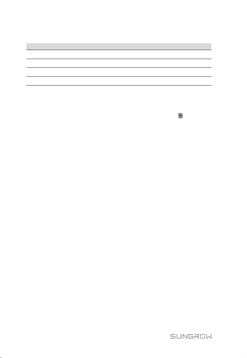
Parameter
Default value
Range
Tab. 8-6 Description of AI parameter
Voltage lower limit(V)
Voltage upper limit(V)
Current lower limit(mA)
Current upper limit(mA)
0 0 ~ 10
10 0 ~ 10
4 4 ~ 20
20 4 ~ 20
DI
Step 1 Click "System" -> "Interface" -> "DI" to enter the corresponding interface.
Step 2 Set the initial status to "NO" or "NC", and click the button to save the
operation.
8.11 About
Click "About" to enter the corresponding interface.
Information such as firmware information of the Logger1000 can be viewed.
Users can scan the QR code via the iSolarCloud APP to add the Logger1000.
50
Page 57
Logger1000
Digital input
Analog input
Grid dispatching center
K1 K2 K3 K4
K5
PC
9 Grid Dispatching Function
Only installation personnel with some communication knowledge can
perform operations described in this chapter.
9.1 Function Description
The Logger1000 not only serves as a communication management device of single
PV array/plant, but also has the power regulation function. Multiple regulation
manners can meet different regulation requirements. The Logger1000 can regulate
the power output of the SUNGROW inverter, and the regulation mainly includes
active power control and reactive power regulation.
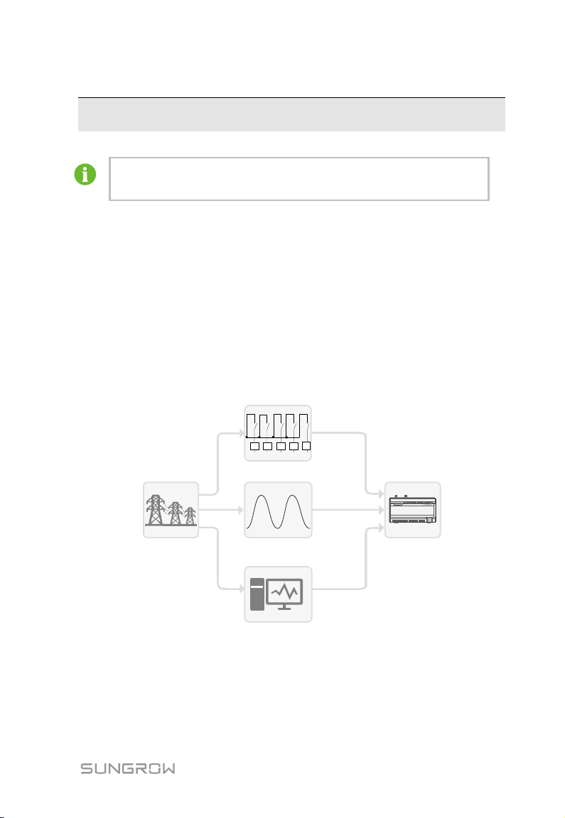
The Logger1000 can control device power output according to the local preset
instructions. In addition, it can receive regulation instructions via the remote
communication (IEC104, MODBUS, and TCP), AI, and dry contact (DI).
Fig. 9-1 Overall frame of power control function
The Logger1000 supports closed-loop power regulation. The regulation accuracy
and real-time performance can be further improved by adding an energy meter.
The Logger1000 supports fast instruction transfer channels (ms-level processing
delay) while ensuring that the dispatching instructions are correctly transmitted to
all inverters.
51
Page 58
9 Grid Dispatching Function User Manual
The corresponding power dispatching function is available only when the
1+ 1- 2+ 2-
AI/DI
3+ 4+3- 4-
123 4
DI DRM
5 R C
24V
OUT
DI
+
-
24V
IN
+
-
0V
Signal
Definition
Enabling switch for converting AI function to DI
function
1+, 1-, 2+, 23+, 3-, 4+, 4-
1, 2, 3, 4, 5
5 independent-input dry contact signal channel
Works together with the DI1 to DI4 to achieve the
DRM function
0V
Input dry contact signal ground
inverter supports active power control, power factor control, and reactive
power regulation!
For details, refer to the inverter user manual or consult the local retailer.
9.2 Interface Description
The Logger1000 is equipped with digital control interfaces and analog control
interfaces for receiving digital instructions and analog instructions sent by the grid
dispatching center.
9.2.1 Digital Control Interface
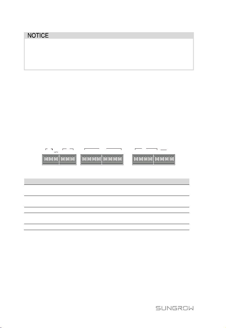
The digital control interfaces are at the bottom of the Logger1000, and a sum of 5
digital input ports are provided, as shown in the figure below.
Tab. 9-1 Digital control interface signal definition
DI
4 input dry contact channels
DRM
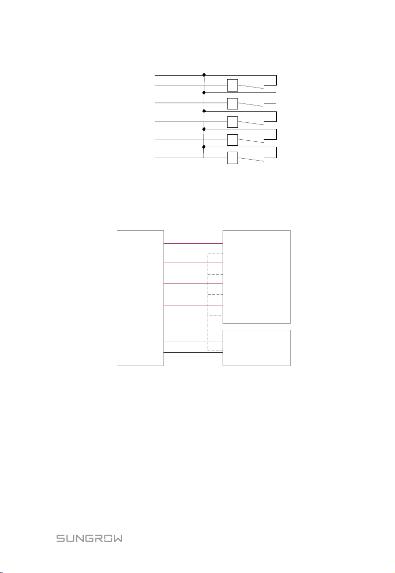
There are 4 ports at the bottom of the Logger1000 compatible with the AI/DI
function. When the DI function of the "AI/DI" port is enabled, use a power cable to
connect the "24V OUT+" port to "DI" port.
Wiring between the Logger1000 and the wireless receiver controller is as follows:
52
Page 59
User Manual 9 Grid Dispatching Function
K1
K2
K3
K4
K5
0V
l
2
3
4
5
Logger1000 Wireless receiver controller
Logger1000
Ripple Control Receiver
1
2
3
4
5
0V
DI 1+
DI 1-
DI 2+
DI 2DI 3+
DI 3DI 4+
DI 4-
Fast-Stop
+
-
In Germany and some other European countries, the grid company uses the Ripple
Control Receiver to convert the grid dispatching signal and send it in a dry contact
manner, In this case, the plant needs to receive the grid dispatching signal in the dry
contact communication manner.
Wiring of the active power dry contact is shown in the figure below:
Wiring of the reactive power dry contact is shown in the figure below:
53
Page 60
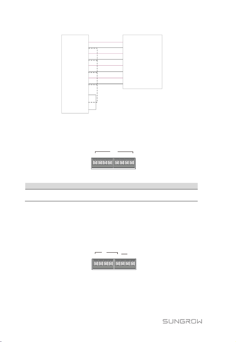
9 Grid Dispatching Function User Manual
Logger1000
Ripple Control Receiver
1+
12+
23+
3-
4+
4-
DI
24 OUT-
24 OUT+
DI 1+
DI 1-
DI 2+
DI 2DI 3+
DI 3DI 4+
DI 4-
1+ 1- 2+ 2-
AI/DI
3+ 4+3- 4-
Signal
Definition
1+, 1-, 2+, 23+, 3-, 4+, 4-
123 4
DI DRM
5 R C
0V
9.2.2 Analog Control Interface
The analog control interfaces are at the bottom of the Logger1000, and a sum of 4
analog input ports are provided, as shown in the figure below.
Tab. 9-2 Analog control interface signal definition
4 analog input channels
The Logger1000 supports 4 inputs of 4~20mA analog currents or 4 inputs of 0~
10V analog voltage.
9.2.3 DRM Control Interface
The DRM control interface are located at the bottom of the Logger1000, as shown in
the figure below.
The DRM interface works together with DI1~DI4 to achieve the DRM function.
Wiring between the Logger1000 and the DRED is as follows:
54
Page 61
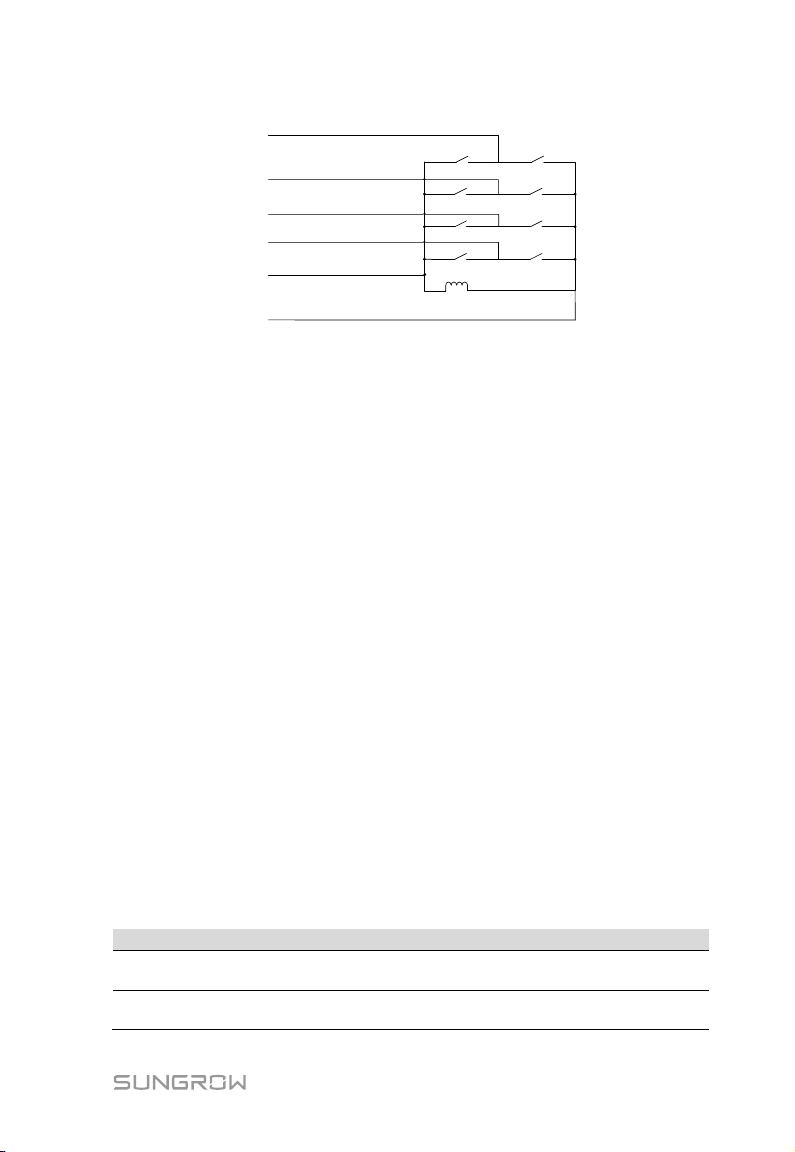
User Manual 9 Grid Dispatching Function
S1
S7
S6
S5
S4
S3
S2
S8
15K
DRED
1
2
3
4
R
C
Logger1000
Parameter
Description
Communication
abnormality output (%)
Communication is abnormal, and specified dispatch
output value is delivered.
Open loop control: Remote monitoring background is
connected and active instruction of remote dispatching is
The DRM interface requires that the Logger1000 can be connected to the DRED via
the corresponding wiring terminal or RJ45 connector.
9.3 Power Control
Power regulation includes active power control and reactive power regulation.
9.3.1 Active Power
Disable
If the inverter needs to operate at full load, the active control mode should be set to
"Disable".
Step 1 Click "Power control" -> "Active power" to enter the active power interface.
Step 2 Set the active control mode to "Disable" and click “Save”.
Remote power control
When the instruction source is IEC104 or MODBUS TCP protocol, set the active
control mode to "Remote power control".
Step 1 Click "Power control" -> "Active power" to enter the active power interface.
Step 2 Set the active control mode to "Remote power control".
Step 3 Set remote dispatching parameters. For specific parameter description, refer
to the following Tab. 9 -3.
Tab. 9-3 Parameter description
Control method
55
Page 62

9 Grid Dispatching Function User Manual
Parameter
Description
sent to the power output port of the inverter, thereby
, remote
and active power compensation ratio is
active power of the meter needs to be
power feed-in.
Unselected
Select energy meter involved in power regulation
Time interval of delivering dispatching instructions
Parameter range: 5~60s
Parameter
Description
Communication
Communication is abnormal, and specified dispatch
inverter, thereby implementing active power control.
achieving active power control.
Closed-loop control:
1) In case no energy meter is selected
monitoring background is connected, active
instruction of remote dispatching is used as target
value,
calculated and sent to the power output port of the
inverter. Generally, this strategy is used for fast and
accurate active power regulation.
2) In case an energy meter is selected, remote
monitoring background is connected, active
instruction of remote dispatching is used as target
value,
collected and used as input parameter, and active
power compensation ratio is calculated and sent to
the power output port of the inverter. Generally, this
strategy is used for anti-backflow or avoiding zero
Select energy meter*
Control cycle
Note: *Only when the control method is set to "Closed-loop control", the parameter
"Select energy meter" is settable.
Step 4 After finishing parameter setting, click "Save" to save the operation.
Local power control
If active dispatching instruction or dispatching target value is used as dispatching
input locally, the active control mode is set to "Local power control".
Step 1 Click "Power control" -> "Active power" to enter the active power interface.
Step 2 Set the active control mode to "Local power control".
Step 3 Set local dispatching parameters. For specific parameter description, refer to
the following Tab. 9-4.
Tab. 9-4 Parameter description
abnormality output (%)
Control method
56
output value is delivered.
Open loop control:At the start time, the locally configured
active instruction is sent to the power output port of the
Page 63
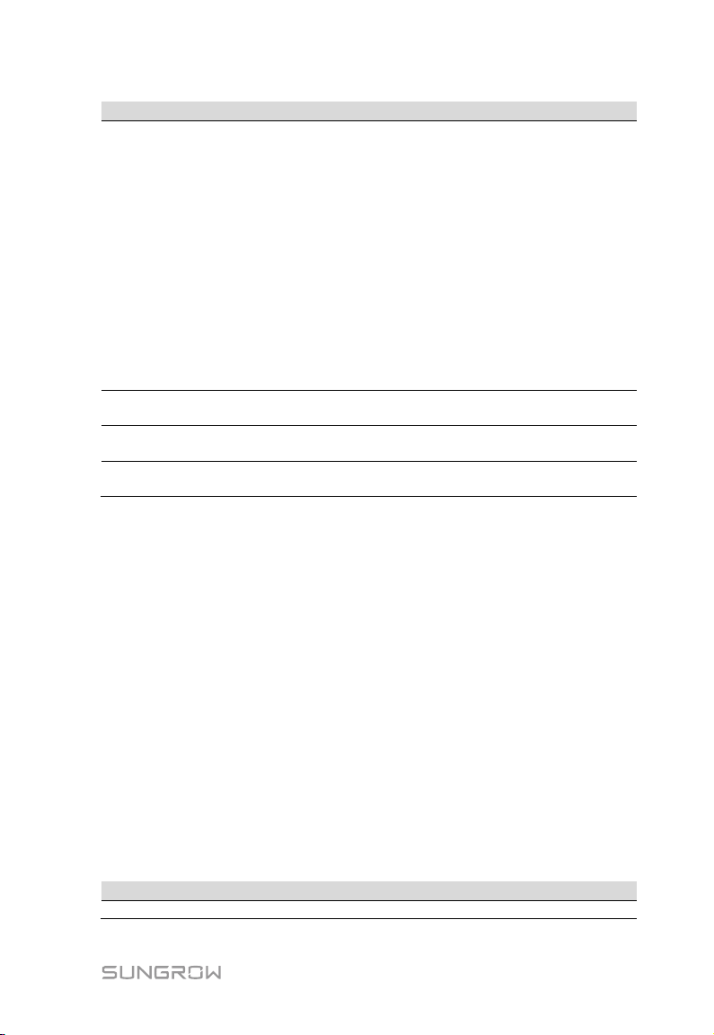
User Manual 9 Grid Dispatching Function
Parameter
Description
Closed-loop control:
power feed-in.
Unselected
Select energy meter involved in power regulation
Time interval of delivering dispatching instructions
Parameter range: 5~60s
kW: set active power value
%: set active power percentage
Parameter
Description
Communication
Communication is abnormal, and specified dispatch
1) In case no energy meter is selected, at the beginning
time, the active instruction configured locally is used
as target value, and active power compensation ratio
is calculated and sent to the power output port of
the inverter. Generally, this strategy is used for fast
and accurate active power regulation.
2) In case an energy meter is selected, at the beginning
time, active instruction configured locally is used as
target value, active power of the meter needs to be
collected and used as input parameter, and active
power compensation ratio is calculated and sent to
the power output port of the inverter. Generally, this
strategy is used for anti-backflow or avoiding zero
Select energy meter*
Control cycle
Q-Method
Note: *Only when the control method is set to "Closed-loop control", the parameter
"Select energy meter" is settable.
Step 4 Add local power control manner
Fill in "Start time" and "Percentage" (fixed value of active power), and click "Save".
Subsequent operation
Delete local power control manner: select a local control manner that needs to be
deleted, and click "Clear data".
AI control
When using the analog signal at the AI port of the Logger1000 as the dispatching
input, set the active control mode to "Analog input".
Step 1 Click "Power control" -> "Active power" to enter the active power interface.
Step 2 Set the active control mode to "Analog input".
Step 3 Set AI control parameters. For specific parameter description, refer to the
following Tab. 9-5.
Tab. 9-5 Parameter description
57
Page 64

9 Grid Dispatching Function User Manual
Parameter
Description
abnormality output (%)
output value is delivered.
Open loop control: Active instruction controlled by AI is
of the meter needs to be collected and used as input
Generally, this strategy is used for
anti-backflow or avoiding zero power feed-in.
Unselected
Select energy meter involved in power regulation
Time interval of delivering dispatching instructions
Parameter range: 5~60s
AI port
AI1~AI4 available
kW: set active power value
%: set active power percentage
Min.
Lower limit: 0.0
When "Q-Method" is set to "%", the upper limit is 100.0%
kW
The minimum difference value between two consecutive
power dispatching instructions
sent to the power output port of the inverter, thereby
achieving active power control.
Closed-loop control:
1) In case no energy meter is selected, active
instruction controlled by AI is used as target value,
and active power compensation ratio is calculated
Control method
Select energy meter*
Control cycle
Q-Method
and sent to the power output port of the inverter.
Generally, this strategy is used for fast and accurate
active power regulation.
2) In case an energy meter is selected, active instruction
controlled by AI is used as target value, active power
parameter, and active power compensation ratio is
calculated and sent to the power output port of the
inverter.
Max.
Step
When "Q-Method" is set to "kW", the upper limit is 999999
Note: *Only when the control method is set to "Closed-loop control", the parameter
"Select energy meter" is settable.
Step 4 After finishing parameter setting, click "Save" to save the operation.
Digital input
When using the digital signal at the DI port of the Logger1000 as the dispatching
input, set the active control mode to "Digital input".
Step 1 Click "Power control" -> "Active power" to enter the active power interface.
Step 2 Set the active control mode to "Digital input".
Step 3 Set DI control parameters. For specific parameter description, refer to the
following Tab. 9-6.
58
Page 65

User Manual 9 Grid Dispatching Function
Parameter
Description
Communication
abnormality output (%)
Communication is abnormal, and specified dispatch
output value is delivered.
Open loop control: Active instruction controlled by DI is
, active
inverter. Generally, this strategy is used for
anti-backflow or avoiding zero power feed-in.
Unselected
Select energy meter involved in power regulation
Time interval of delivering dispatching instructions
Parameter range: 5~60s
kW: set active power value.
%: set active power percentage.
Tab. 9-6 Parameter description
sent to the power output port of the inverter, thereby
achieving active power control.
Closed-loop control:
1) In case no energy meter is selected
instruction controlled by DI is used as target value,
and active power compensation ratio is calculated
and sent to the power output port of the inverter.
Control method
Select energy meter*
Control cycle
Q-Method
Generally, this strategy is used for fast and accurate
active power regulation.
2) In case an energy meter is selected, active instruction
controlled by DI is used as target value, active power
of the meter needs to be collected and used as input
parameter, and active power compensation ratio is
calculated and sent to the power output port of the
Note: *Only when the control method is set to "Closed-loop control", the parameter
"Select energy meter" is settable.
Step 4 Add digital input manner
Select the desired DI channel, fill in the "Percentage"(fixed value of active power),
and click "Save".
Subsequent operation
Delete digital input manner: select a digital input manner that needs to be deleted,
and click "Clear data".
DRM mode
When using the digital signal at the DI port (DI1 ~ DI4) of the Logger1000 as the
dispatching input, set the active control mode to "DRM mode".
Step 1 Click "Power control" -> "Active power" to enter the active power interface.
Step 2 Set the active control mode to "DRM mode" and click “Save”.
59
Page 66

9 Grid Dispatching Function User Manual
Parameter
Description
Communication
abnormality output (%)
Communication is abnormal, and specified dispatch
output value is delivered.
Open loop control: Remote monitoring background is
ed as input
Generally, this strategy is used for improving the power
factor of the property boundary point.
Select energy meter*
Select energy meter involved in power regulation
Time interval of delivering dispatching instructions
Parameter range: 5~60s
9.3.2 Reactive Power
Disable
If the grid company does not need the power plant to adjust the voltage at the
grid-connection point, and the inverter does not need to cooperate with the grid for
reactive power compensation, the inverter keeps operating in the
reactive-forbidden output state, and the Reactive control mode is set to "Disable".
Step 1 Click "Power control" -> "Reactive power" to enter the reactive power
interface.
Step 2 Set the reactive control mode to "Disable" and click “Save”.
Remote power control
When the instruction source is IEC104 or MODBUS TCP protocol, set the "Reactive
control mode" to "Remote power control".
Step 1 Click "Power control" -> "Reactive power" to enter the reactive power
interface.
Step 2 Set the "Reactive control mode" to "Remote power control".
Step 3 Set remote dispatching parameters. For specific parameter description, refer
to the following Tab. 9-7.
Tab. 9-7 Parameter description
connected and active instruction of remote dispatching is
sent to the power output port of the inverter, thereby
achieving active power control.
Closed-loop control: Remote monitoring background is
Control method
Control cycle
connected and reactive instruction of remote dispatching
is used as target value, reactive power and power factor of
the meter need to be collected and us
parameters, and reactive power compensation ratio is
calculated and sent to power output port of the inverter.
Note: *Only when the control method is set to "Closed-loop control", the parameter
"Select energy meter" is settable.
60
Page 67
User Manual 9 Grid Dispatching Function
Parameter
Description
Communication
abnormality output (%)
Communication is abnormal, and specified dispatch
output value is delivered.
t the beginning time, reactive
for improving the power factor of the property boundary
point.
Select energy meter*
Select energy meter involved in power regulation
Time interval of delivering dispatching instructions
Parameter range: 5~60s
PF: set the power factor as the target value
%: set reactive power percentage.
Step 4 After finishing parameter setting, click "Save" to save the operation.
Local power control
If reactive dispatching instruction or dispatching target value is used as dispatching
input locally, the reactive control mode is set to "Local power control".
Step 1 Click "Power control" -> "Reactive power" to enter the reactive power
interface.
Step 2 Set the "Reactive control mode" to "Local power control".
Step 3 Set local dispatching parameters. For specific parameter description, refer to
the following Tab. 9-8.
Tab. 9-8 arameter description
Open loop control:At the start time, the locally configured
active instruction is sent to the power output port of the
inverter, thereby implementing reactive power control.
Closed-loop control: A
Control method
instruction configured locally is used as target value,
reactive power and power factor of the meter need to be
collected and used as input parameters, and reactive
power compensation ratio is calculated and sent to power
output port of the inverter. Generally, this strategy is used
Control cycle
Q-Method
Note: *Only when the control method is set to "Closed-loop control", the parameter
"Select energy meter" is settable.
Step 4 Add local power control manner
Fill in "Start time" and "Percentage"(PF), and click "Save".
Subsequent operation
Delete local power control manner: select a local power control manner that needs
to be deleted, and click "Clear data".
61
Page 68

9 Grid Dispatching Function User Manual
Parameter
Description
Communication
abnormality output (%)
Communication is abnormal, and specified dispatch
output value is delivered.
Open loop control: Reactive instruction controlled by AI is
e inverter, thereby
Generally, this strategy is used for improving the power
factor of the property boundary point.
Select energy meter*
Select energy meter involved in power regulation
Time interval of delivering dispatching instructions
Parameter range: 5~60s
AI port
AI1~AI4 available
PF: set the power factor as the target value
%: set reactive power percentage
When "Q-Method" is set to "%", the parameter ranges from
from -1 to -0.8 or 0.8 to 1.
The minimum difference value between two consecutive
power dispatching instructions
When the parameter "Q-Method" is set to PF, dispatching
output maintains to be PF±1
AI control
When using the analog signal at the AI port of the Logger1000 as the dispatching
input, set the reactive control mode to "Analog input".
Step 1 Click "Power control" -> "Reactive power" to enter the reactive power
interface.
Step 2 Set the reactive control mode to "Analog input".
Step 3 Set AI control parameters. For specific parameter description, refer to the
following Tab. 9-9.
Tab. 9-9 Parameter description
sent to power output port of th
achieving active power control.
Closed-loop control: Reactive instruction controlled by AI
Control method
is used as target value and reactive power and power
factor of the meter need to be collected and used as input
parameters, and reactive power compensation ratio is
calculated and sent to power output port of the inverter.
Control cycle
Q-Method
Min. / Max.
Step
Hysteresis range**
-100.0% to 100.0%.
When "Q-Method" is set to "PF", the parameter ranges
Note: *Only when the control method is set to "Closed-loop control", the parameter
"Select energy meter" is settable.
** Only when the control method is set to "Open loop control" and the Q-Method to
"PF" or when the control method is set to "Closed-loop control", an energy meter is
selected, and the Q-Method is set to "PF", the parameter "Hysteresis range" is
settable.
62
Page 69
User Manual 9 Grid Dispatching Function
Parameter
Description
Communication
abnormality output (%)
Communication is abnormal, and specified dispatch
output value is delivered.
Open loop control: Reactive instruction controlled by DI is
sent to power output port of the inverter, thereby
rategy is used for improving the power
factor of the property boundary point.
Select energy meter*
Select energy meter involved in power regulation
Time interval of delivering dispatching instructions
Parameter range: 5~60s
PF: set the power factor as the target value
%: set reactive power percentage
The open-loop control has the "PF" Q-Method, and the closed-loop
Step 4 After finishing parameter setting, click "Save" to save the operation.
Digital input
When using the digital signal at the DI port of the Logger1000 as the dispatching
input, set the reactive control mode to "Digital input".
Step 1 Click "Power control" -> "Reactive power" to enter the reactive power
interface.
Step 2 Set the reactive control mode to "Digital input".
Step 3 Set DI control parameters. For specific parameter description, refer to the
following Tab. 9-10.
Tab. 9-10 Parameter description
achieving active power control.
Closed-loop control: Reactive instruction controlled by DI
Control method
is used as target value and reactive power and power
factor of the meter need to be collected and used as input
parameters, and reactive power compensation ratio is
calculated and sent to power output port of the inverter.
Generally, this st
Control cycle
Q-Method
Note: *Only when the control method is set to "Closed-loop control", the parameter
"Select energy meter" is settable.
control has the "PF" Q-Method only when the meter is selected.
Step 4 Add digital input manner
Select the desired DI channel, fill in the "Percentage "(PF), and click "Save".
Subsequent operation
Delete digital input manner: select a digital input manner that needs to be deleted,
and click "Clear data".
63
Page 70

9 Grid Dispatching Function User Manual
Parameter
Description
Enable: The emergency button is turned on, and inverters are
restored to the boot in batch.
DI port
Associated with DI5 channel
9.3.3 Emergency Button
In inverters need to be stopped in batch, select the button "Emergency button".
Click "Power control" -> "Emergency button" to enter the corresponding interface.
Emergency button
stopped in batch.
Disable: The emergency button is turned off, and inverters are
64
Page 71
10 Device Maintenance
Due to the effect of ambient temperature, humidity, dust and vibration, the inner
components of the Logger1000 will be aging and worn out. To ensure the system
safety and maintain the efficiency of the Logger1000, it is necessary to carry out
routine and periodic maintenance.
All measures, which can help the Logger1000 to keep good working conditions, are
within the maintenance scope.
10.1 Safety Instructions
10.1.1 Safety Rules
Only qualified personnel can perform the work described in this chapter.
Do not leave any screws, washers or other metallic parts inside the
Logger1000 to avoid damages to the Logger1000.
Wait at least 5 minutes after the Logger1000 stops and then perform
operations on it.
10.1.2 Five Safety Rules
Respect the following five rules thought the maintenance or service process to
ensure personnel safety.
Disconnect the Logger1000 from all the external connections and internal power
supplies.
Ensure that the Logger1000 will not be inadvertently connected.
Ensure that the Logger1000 is voltage free with a multimeter.
Connect necessary grounding cables.
Cover the electrical components with insulation cloth during operation.
65
Page 72
10 Device Maintenance User Manual
Item
Method
Check to make sure there is no strong EMC interference
the Logger1000
Check to make sure the power supply voltage is normal
properly
Clean the enclosure, circuit board and the components
hole and the ensure it is not
covered
Check if the screws of the control terminals are loose.
Check if the connection copper bar or screws are
connection
Log in Web to check the device communication situation
og in Web to check the parameter setting of the
Log in Web to check the software version of the Logger1000
10.2 Maintenance
Recommended routine maintenance work is shown in the following table.
Working
environment
Hardware
maintenance
System cleaning
Terminal and cable
connection
Software
maintenance
device around the Logger1000
Check to make sure there is no hot source around the
Logger1000.
Check to make sure there is no corrosive materials around
Check to make sure the cables are connected firmly
Check to make sure the grounding cable is grounded
Check the heat dissipation
Refasten them with screwdriver if necessary;
discoloring.
Visually check the wiring layout and the device terminal
L
Logger1000
10.3 Troubleshooting
The grounding cable must be grounded reliably. Otherwise, electric shock
can cause personal injury!
The common faults and troubleshooting is shown in the table below. If the problem
still cannot be removed by following the instruction in this manual, please contact
SUNGROW.
66
Page 73
User Manual 10 Device Maintenance
Fault
Cause
Corrective measures
1. The power supply
3. Logger1000 fault
1. Connect the power cable to the
power supply terminal of the
3. Contact SUNGROW
find any
1. The RS485 port is not
the connection cable is
loose or connected
support automatic search
are not manually added,
The address of the
added device is
normally.
cable connection; reconnect and
Baud rate and the communication
lly add the devices such as
0 displays
the device
state as
Communication cable
s loose or
2. The device operates
1. Check the cable connection between
the device and Logger1000; and
so, research or add the device
“Delete”.
ate with
1. The network between the
Logger1000 and the
2. Network parameter
configuration is incorrect.
1. Check if the Ethernet port of the
set correctly.
Power-on
fault
Cannot
device
The
Logger100
disconnecti
on
Cannot
communic
the
backgroun
d
terminal of the Logger1000
has no power connection
2. Power source failure
connected to any devices or
reversely.
2. The RS485
communication parameters
are set incorrectly.
3. The devices that do not
such as Meteo Station and
energy meter.
4.
manually
inconsistent with the actual
device address
5. Device does not operate
1.
between the device and the
Logger1000 i
disconnected.
abnormally
3. The device is removed or
its configuration is changed
background is failed.
setting is incorrect.
3. The forwarding protocol
67
Logger1000
2. Replace the power source
1. Check the RS485 communication
tighten the cable if necessary.
2. Check the RS485 communication
parameter setting; and make sure the
address setting are correct.
3. Manua
Meteo Station and energy meter.
4. Check the device address setting.
5. Check the device operation status.
reconnect and tighten the cable if
necessary.
2. Power on the device if the device
connection is correct
3. Check if there is a device replaced. If
manually.
If the device is removed, conduct the
“Device List” operation through the
Logger1000 is connected to the PC or
router correctly.
2. Check if the network parameter is set
correctly.
3. Check if the forwarding protocol is
Page 74
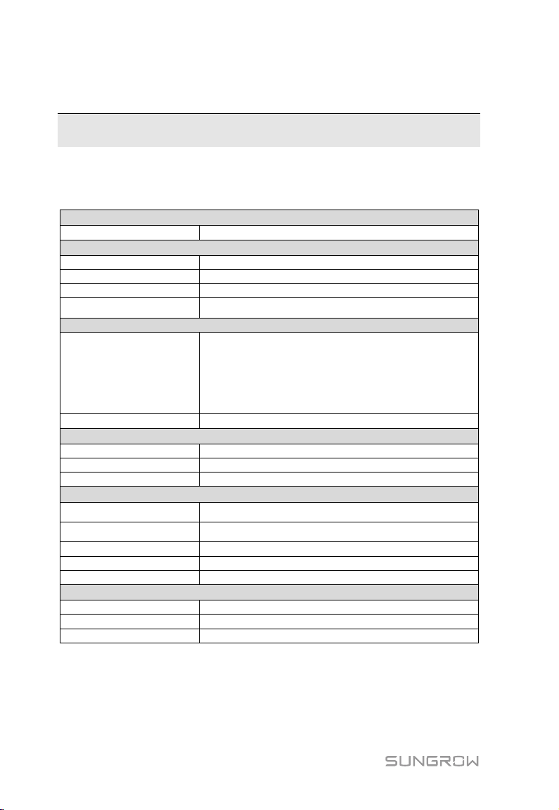
Communication
Max. number of devices
30 at most
Communication ports
RS485 interface
3
Ethernet
1 x RJ45, 10/100/1000Mbps
Digital input
5, Max. 24VDC
Wireless Communication
LTE(FDD): B1, B3, B5, B8
WCDMA: B1, B8
WiFi communication
802.11 b/g/n/ac; HT20/40/80MHz; 2.4GHz/5GHz
Power Supply
DC input
24VDC, max. current: 1.2A
DC output
24VDC, 0.5A
Power consumption
<10W
Ambient Conditions
Relative air humidity
≤95% (no condensation)
Elevation
≤4000m
Protection class
IP20
Mechanical Parameters
Dimensions (W x H x D)
200 x 110 x 60 mm
Weight
500 g
Mounting type
Top-hat rail mounting/ wall mounting
11 Appendix
11.1 Technical Data
Analog input
4G Communication
Operating temperature
Storage temperature
11.2 Quality Guarantee
SUNGROW shall service or replace the faulty product for free within the warranty
4, support 4~20mA or 0~10VDC
LTE(TDD): B38,B39, B40, B41
TD-SCDMA: B34, B39
CDMA: BC0
GSM: 900/1800 MHz
-30℃ ~ +60℃
-40℃ ~ +80℃
68
Page 75
User Manual 11 Appendix
period.
Evidence
Within the warranty per iod, SUNGROW shall require the customer to present the
purchase invoice and date. The trademark on the product shall be clearly visible, and
SUNGROW shall hold no liability if otherwise.
Conditions
The replaced failure product needs to be disposed of by SUNGROW.
The client needs to reserve enough troubleshooting time for SUNGROW.
Exclusion of Liability
The following cases shall void the warranty claims of SUNGROW.
The free warranty periods for the whole machine/components have expired
The device is damaged during transport
The device is installed, altered, or operated incorrectly
The device operates in an environment harsher than that described in this
manual
The fault or damage is caused due to installation, maintenance, alteration, or
disassembly performed by persons not from SUNGROW
The fault or damage caused by using non-standard components or software or
using components or software not from SUNGROW
The installation and use do not comply with stipulations of relevant international
standards
The damage is caused by unpredictable factors
For the foregoing faults or damages, SUNGROW can provide a paid service at the
request of the client after judgment.
The dimensions and parameters of the device are subject to changes
without notification, and reference can be made to the latest document.
Software licenses
It is prohibited to use data contained in firmware or software developed by
SUNGROW, in part or in full, for commercial purposes by any means.
69
Page 76

11 Appendix User Manual
China (HQ)
Australia
Brazil
France
Germany
Greece
It is prohibited to perform reverse engineering, cracking, or any other operations
that compromise the original program design of the software developed by
SUNGR OW.
11.3 Contact Information
Should you have any question about this product, please contact us.
We need the following information to provide you the best assistance:
Type of the device
Serial number of the device
Fault code/name
Brief description of the problem
Sungrow Power Supply Co., Ltd
Hefei
+86 551 65327834
Sungrow Do Brasil
Sao Paulo
+55 11 2366 1957
Sungrow Deutschland GmbH
München
+49 89 324 914 761
70
Sungrow Australia Group Pty. Ltd.
Sydney
+61 2 9922 1522
Sungrow France – Siege Social
Paris
Service Partner – Survey Digital
+30 2106044212
Page 77
User Manual 11 Appendix
India
Italy
Japan
Korea
Malaysia
Philippines
Thailand
Spain
Romania
Turkey
Sungrow (India) Private Limited
Gurgaon
+91 080 41201350
Sungrow Japan K.K.
Tok yo
+ 81 3 6262 9917
Sungrow SEA
Selangor Darul Ehsan
+60 19 897 3360
Sungrow Thailand Co., Ltd.
Bangkok
+66 891246053
Sungrow Italy
Milano
Sungrow Power Korea Limited
Seoul
+82 70 7719 1889
Sungrow Power Supply Co., Ltd
Mandaluyong City
+63 9173022769
Sungrow Ibérica S.L.U.
Navarra
Service Partner – Elerex
+40 241762250
71
Sungrow Deutschland GmbH Turkey
Istanbul Representative Bureau
Istanbul
+90 212 731 8883
Page 78

11 Appendix User Manual
UK
U.S.A, Mexico
Vietnam
Sungrow Power UK Ltd.
Milton Keynes
+44 (0) 0908 414127
Sungrow Vietnam
Hanoi
+84 918 402 140
Sungrow USA Corporation
Phoenix Arizona
+1 833 747 6937
72
 Loading...