

Page 1
1
Motion Activated Dual Light & Video Camera
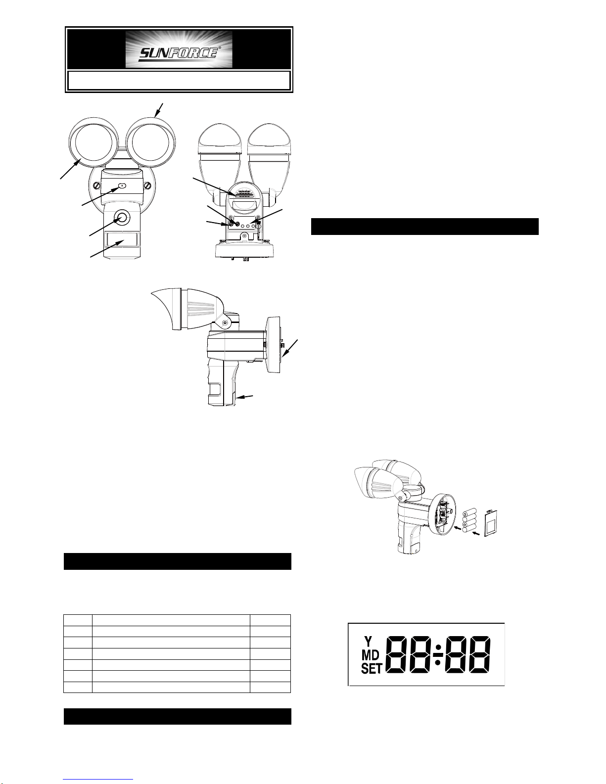
① Floodlight
② Lampshade
③ Microphone
④ Camera
⑤ PIR (Motion Sensor)
⑥
Warning Speaker
⑦ Lux Control Knob
⑧ Ti m e Control Knob (PIR trigger time)
⑨ LCD control panel and Setting buttons
⑩ Battery Cover
⑪ SD Card Slot
PACKAGE CONTENTS
Please check y o u r box carefully and confirm the
contents listed below are included.
No.
Item
Qty
1
Base Unit (model 82346)
1
2
AA Size 1.5V Alkaline Battery
4
3
2GB SD Card
1
4
Screw Pack
1
5
Halogen Bulb
2
6
Operating Instruction Manual
1
INTRODUCTION
Y o u r Motion Activated Dual Light & Video Camera is a
unique surveillance system for your home or business.
At night, the built-in passive infrared (PIR) motion
sensor turns on the light when it detects motion in its
coverage area, so that camera images can be clearly
seen. During the day, the built-in photocell sensor
saves electricity by automatically deactivating the light.
Y our unit comes with a built-in SD card slot for
additional storage; accepts memory storage up to
32GB. Customized sound recording is also available.
The Motion Activated Dual Light & Video Camera is
designed for indoor/outdoor use and your unit can be
controlled by remote control.
Note: Read this entire manual before installation
BEFORE START
Please follow the steps below for installation;
NOTE: The alkaline batteries function unit settings only.
Do NOT install the batteries until you're ready to set the
functions and mount the unit. The battery power will last
about 1 hour after installed.
Caution: After completion of all function settings,
please remove the batteries from the unit prior to
installation.
POWERING UP
The Motion Activated Dual Light & Video Camera is
powered by batteries for optional setting selection.
Press and release the battery cover and insert 4 AA
size 1.5V alkaline batteries (FIGURE 1). Re-cover the
battery housing.
FIGURE 1
Once the Motion Activated Dual Light & Video Camera
is powered up, it enters PIR warm up mode. The LCD
displays as below (FIGURE 2).
FIGURE 2
After 3 seconds, the unit enters standby mode (as
shown in FIGURE 3). It implies the unit is ready for
Rear View
Side View
⑪
Front View
Page 2
2
function setting.
FIGURE 3
SD CARD INST ALLATION
Once the unit is powered up, if no SD card is found, a
beep sound will be played for 10 seconds every hour.
For security reasons, the 2GB SD card is sealed in the
unit. There is no need to take it out it is needed or to
upgrade it with a larger capacity SD card (up to 32GB).
Note: Make sure the unit is powered OFF before
inserting or removing SD cards. If the unit is not
powered off, press ‘SET’ to enter scene mode and then
press ‘Up’ or ‘Down’ to choose Scene 4. After the
unit is set to Scene 4, insert or remove the SD card
accordingly. T o insert an SD card:
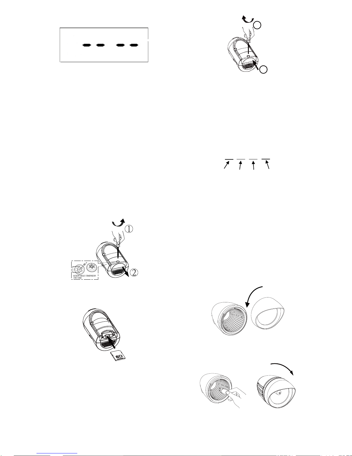
(1) T o open the SD card cover, insert the wrench
provided in the screw pack and turn 3-5 times
counterclockwise. The cover will slide down (the
screw will stay in place to avoid losing it) (FIGURE
4).
FIGURE 4
(2) Insert SD card into the card slot (FIGURE 5).
FIGURE 5
(3) Refit the cover, and fasten the screw clockwise
(FIGURE 6).
1
2
FIGURE 6
(4) Once the unit is powered up, it will detect the
existence of a ‘LIGHT’ folder. All recorded files
will be saved in this folder. If the folder isn’t found,
the SD card will be formatted while a ‘LIGHT’ folder
will be generated.
(5) Once a video recording is taken, it will be saved
in .asf format under the path
LIGHT\YMD\time+serial no.asf. Below is an
example of a self generated file name:
17075600
Note: Oldest videos are deleted and overwritten as the
card reaches capacity to ensure recent events are
always available.
BULB INSTALLATION
C AUT I ON : Always handle quartz halogen bulb with a
soft cloth. Do not touch the bulb with your bare hands
as it will shorten the bulb life.
(1) Do not touch the light while it is in use or still hot
Allow it to cool off (about 5 minutes) before
touching it
(2) Do not use halogen bulb rated higher than 60 watts
for each lamp
(3) Disconnect the power cord or wall switch
(4) Turn the lampshade counterclockwise to remove it
FIGURE 7).
FIGURE 7
(5) Install a G9 halogen bulb to its lamp holder
(FIGURE 8a).
FIGURE 8a & 8b
Hour
Minute
Seconds
Serial No.
Page 3
3
(6) After bulb is in place, reposition the lampshade by
turning clockwise. (FIGURE 8b).
FUNCTION SETTINGS
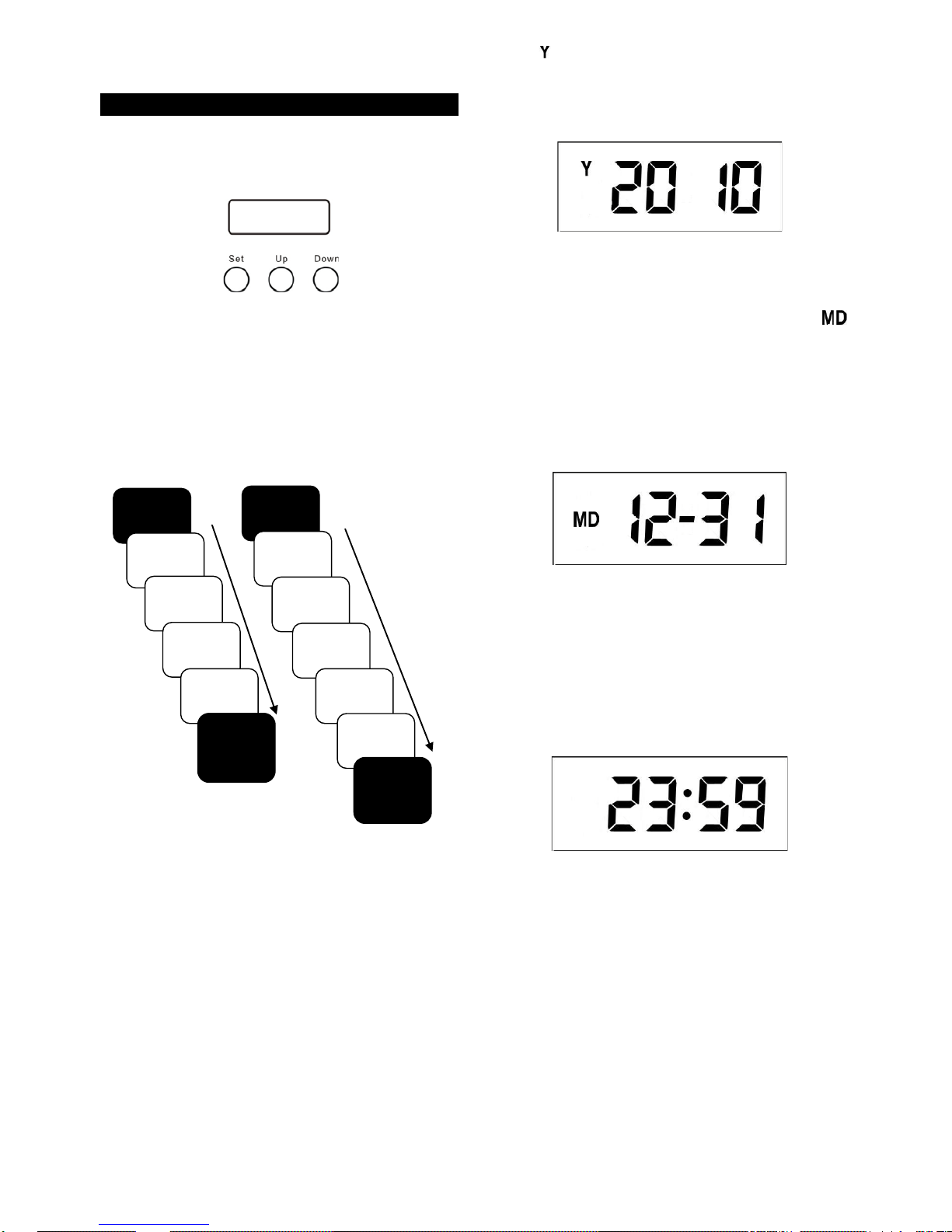
The Motion Activated Dual Light & Video Camera has
an LCD panel with three control knobs: Set, Up and
Down (FIGURE 9).
FIGURE 9
TWO SETTING FUNCTIONS
The Motion Activated Dual Light & Video Camera has
two setting functions: general setting and local time
setting. In standby mode, prompt pressing or
pressing for about 3 seconds on the Set button can
lead to different settings. The following diagram
illustrates setting sequences.
FIGURE 10
LOCAL TIME SETTINGS
The Motion Activated Dual Light & Video Camera has
‘pre-record’ and ‘time record’ functions. The pre-record
time is the length of time before the unit detects motion;
varies from 4 to 12 seconds. During this time, video will
be taken. To ensure you get correct time and day for
the recorded images, it is important to set the y e a r ,
month, day , and time accurately. Please follow the
steps below to set up local time.
1 . YE AR
Under standby mode (FIGURE 3), press Set for 3
seconds and light flashes once to enter local time.
When displays on the LCD screen, it is ready to be
set.
Y ear range is between 2010 and 2099. Press Up or
Down to select correct year, as shown below:
FIGURE 11
2. MONTH & DATE
Once year setting is complete, press Set and
displays on the LCD. The unit is ready for month and
date settings.
Month ranges from 1 to 12. Press Up or Down to select
correct month. The press Set to adjust the date. The
digit will not flash. Simply press Up or Down to select
correct date. The date ranges from 1 to 31. The LCD
shows as below:
FIGURE 12
3. HOUR & MINUTE
Now press Set to enter the hour and minute settings.
Hour ranges from 00 to 23. Press Up or Down to select
correct hour. Then press Set to adjust the minutes.
The digit will not flash. Simply press Up or Down to
select. Minute ranges from 00 to 59. The LCD shows
as below:
FIGURE 13
After settings are completed, press Set and LCD
returns back to standby mode (FIGURE 3). This
implies the local time setting is completed. PIR stops
detecting function for one minute.
Note: If no action is taken within 12 seconds, the LCD
returns back to standby mode and your settings are not
saved. To ensure the settings have been saved
properly, always keep pressing Set until LCD returns
back to Standby Mode.
GENE R AL SETTINGS
1. SCENE MODE
Scene selection allows you to choose the most suitable
Standby
Mode
Scene
Mode
Warning
Sound
PIR
Sensitivity
ID Code
Learning
Standby
Mode
(completed)
General Setting
(Prompt Pressing)
Standby
Mode
Year
Setting
Month
Setting
Date
Setting
Hour
Setting
Minute
Setting
Standby
Mode
(completed)
Local Time Setting
(3 Second Pressing)
Page 4
4
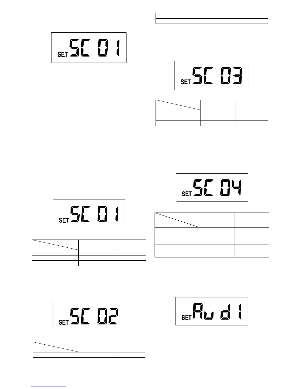
combination of the unit’s functions. In standby mode
(FIGURE 3), press Set to enter scene mode. The LCD
shows as below:
FIGURE 14
Scene one is the preset mode. Press Set and the light
turns on to remind user that the unit is operating. Four
scenes are available for selecting. Press Up or Down
to change the scene.
After desired scene is selected the light flashes once
and then turns on steadily for 10 seconds. This implies
the scene change is in progress. Once the light turns off,
if you wish to save the setting or skip other settings,
keep pressing Set until LCD returns back to standby
mode.
Note: Under scene mode, if no action is taken within 12
seconds, LCD returns back to standby mode and the
light turns off; the setting isn’t saved.
There are 4 scene modes:
1.1 Scene 1
Al l armed mode (FIGURE 15). Once the PIR detects
motion, the camera and light turn on and the
microphone starts recording. Warning sound plays for
10 seconds.
FIGURE 15
Ambient Light
Function
Day
Night
Camera & MIC
On
On
Warning Speaker
On
On
Light
On
On
1.2 Scene 2
Once PIR detects motion, the camera and microphone
start recording. Depending on the ambient light (day or
night) the speaker and light turn on.
FIGURE 16
Ambient Light
Function
Day
Night
Camera & MIC
On
On
Warning Speaker
On
Off
Light
Off
On
1.3 Scene 3
Once PIR detects motion, the camera and microphone
start recording. Depending on the ambient light (day or
night) speaker and light turn on.
FIGURE 17
Ambient Light
Function
Day
Night
Camera & MIC
On
On
Warning Speaker
Off
On
Light
Off
On
1.4 Scene 4
The camera and warning speaker are off. This is
energy saving mode. Once PIR detects motion,
depending on the ambient light (day or night) the light
turns on/off. The light can also be turned on/off via a
remote control.
FIGURE 18
Ambient Light
Function
Day
Night
Camera & MIC
Off
Off
Warning Speaker
Off
Off
Light
Off
(Remote Control
ON/OFF)
On
(Remote Control
ON/OFF)
Note: In Scene 4, local time setting is not available
2. WARNING SOUNDS
In scene mode, press Set to enter warning sound
settings . T he LCD shows as below:
FIGURE 19
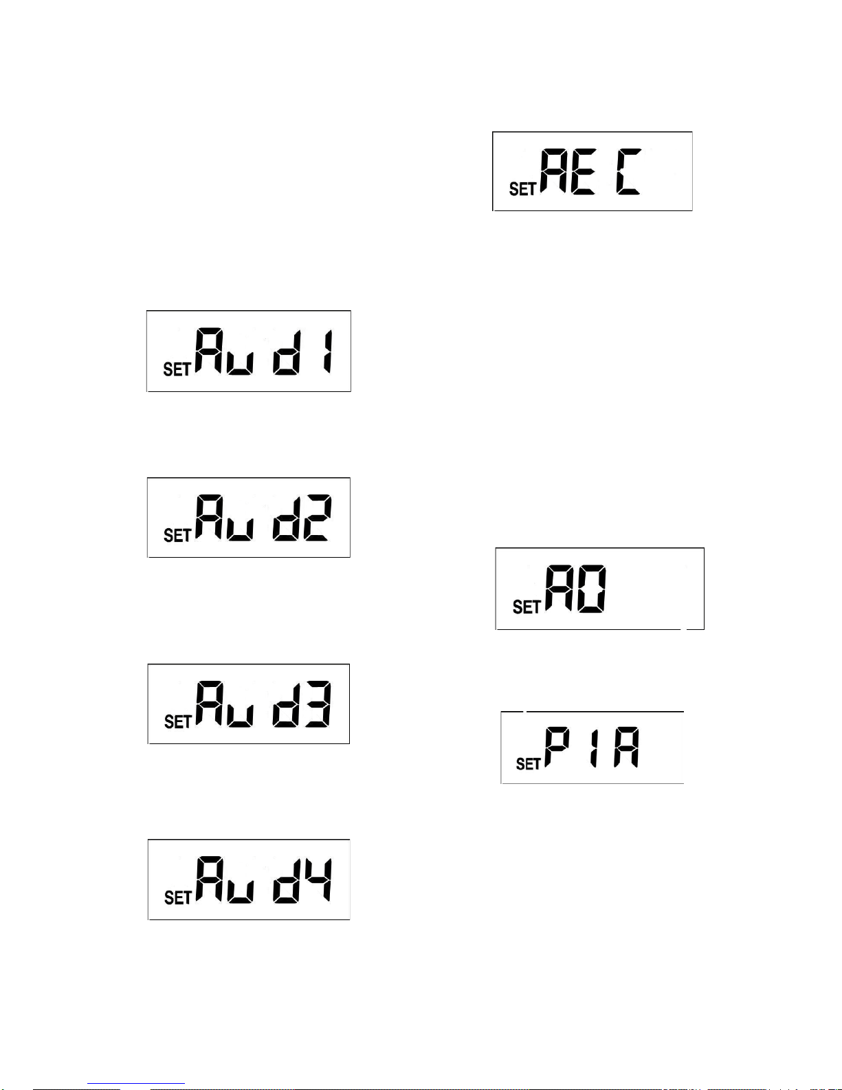
Warning sound 1 is the preset sound. 5 warning
sounds are available for selecting. Warning sounds
3 and 4 are open for your voice/sound recording. The
pla ytime for each warning sound is 10 seconds, and the
Page 5
5
sound volume is 85 dB at 30 cm (11.8 in.) distance.
Press Set; the light is still on to remind user the unit is
operating. 5 warning sounds are available for selecting,
press Up or Down to change warning sound.
After desired sound is selected, if you wish to skip other
settings keep pressing Set until LCD returns back to
standby mode which implies setting is completed.
Note: Under warning sound mode, if no action is taken
within 12 seconds, the LCD returns back to the standby
mode and the light turns off. T he setting is not saved.
There are 5 warning sounds:
2.1 Warning Sound 1
Pre-set alarm sound (this cannot be changed)
FIGURE 20
2.2 Warning Sound 2
Dog barking sound (this cannot be changed)
FIGURE 21
2.3 Warning Sound 3
Open for user recording; you can record your own
audio warning.
FIGURE 22
2.4 Warning Sound 4
Open for user recording; you can record your own
audio warning.
FIGURE 23
Built-in microphone is used for video recording and for
creating your unique warning sounds.
T o create your unique sounds (warning sound 3 & 4):
a. Select warning sound # 3 or 4
b. Press Set for 3 seconds. The light flashes once to
imply the unit is ready for recording
c. Wait for 5 seconds. The LCD shows ‘REC’ and the
recording can begin (FIGURE 24).
FIGURE 24
d. Record time is 10-seconds
e. After recording, the LCD returns back to warning
sound 3 or 4 (FIGURE 22 or 23).
f. The unit will replay the recorded sound for
verification
g. After sound is played, the LCD returns back to
standby mode (FIGURE 3). Sound recording and
warning sound selection is completed. Note: PIR
stops detecting function for one minute
h. If warning sound 1, 2 or 5 is selected, press Set for
3 seconds so you will not execute recording
function. Ten seconds after LCD returns back to
standby mode, the setting of warning sound is
completed.
Note: If you wish to execute sound recording while the
unit is performing video recording, the sound recording
will not be executed until video recording is completed.
2.5 Warning Sound 5 (Mute Mode)
Mute mode (this cannot be changed)
FIGURE 25
3. PIR SENSITIVITY
Under warning sound mode, press Set to enter PIR
sensitivity selection.
FIGURE 26
Press Set. The light is still on to remind user the unit is
operating. 4 PIR sensitivities are available for selecting.
Press Up or Dow n to change sensitivity. PIR sensitivity
#1 is the highest sensitivity and the preset value.
After desired sensitivity is selected, if you wish to skip
the other settings, keep pressing Set until LCD returns
back to standby mode which implies setting is
completed.
The PIR sensor can be swiveled in different directions
to adjust detection coverage.
Note: When in PIR sensitivity settings, if no action is
taken within 12 seconds, the LCD returns back to
Page 6
6
standby mode and the light turns off. The setting is not
saved.
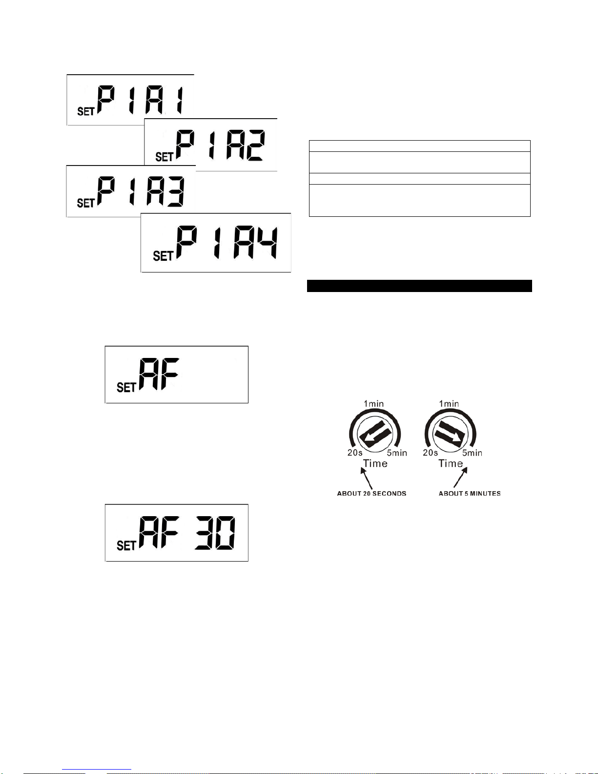
There are 4 PIR sensitivity displays:
FIGURE 27
4. ID CODE LEARNING
When in PIR sensitivity settings, press Set to enter ID
code learning mode. The LCD displays as below:
FIGURE 28
Press Set and the light stays on to remind user the unit
is operating. Once the unit enters ID code learning
mode, press Set for 3 seconds. The light will flash and
the unit starts ID code learning. A t hirty second
countdown will start and the LCD displays as per below
(FIGURE 29);
FIGURE 29
If ID code learning is not finished within 30 seconds, it
fails coding and the LCD returns back to standby mode.
If ID code learning is successful, the LCD returns back
to standby mode and PIR stops detecting function for
one minute.
Once the unit receives RF signals for scene changing,
the light flashes once and then turns on steadily for 10
seconds implying the scene change is in progress.
After 10 seconds the light turns off. The setting is
completed within one minute after the RF signal is
received.
The unit can learn up to 12 ID codes. If you ever wish
to clear ID codes, enter ID code learning mode. The
thirty second countdown starts and press Set for 6
seconds. Please note that when ID code clearing is
executed, ALL ID codes recorded in the unit will be
cleared.
T o ensure learning or clearing is successful, you can
use the remote control to switch between scenes.
Please refer to the user manual for the remote control
for more operating information.
If unit receives TURN ON signal
It operates as a working light while the function of
camera and PIR detection is off
If unit receives TURN OFF signal
The PIR and LUX detection of the unit are still
active, but the light only turns on at night while
camera is off
Note: Under ID code learning mode, if no action is
taken within 12 seconds the settings are not saved and
the LCD returns back to standby mode (the light turns
off).
SETTING THE LIGHTING SYSTEM
(1) TIME ADJUSTMENT
The TIME adjustment controls how long the light stays
on after motion has been detected, as well as video
recording time. Three lengths of time are available for
selection: 20 seconds, 1 minute and 5 minutes. Turn
the TIME control knob to the position of 20s, 1min or
5min (FIGURE 30). Please ensure the control knob
has been turned and set to the accurate position.
FIGURE 30
Note: While setting the time, if the PIR keeps detecting
motion, the lighting time will be extended (video
extended as well). Once time is up (i.e. 20 seconds, 1
minute or 5 minutes), the recording will stop. It takes 2
seconds before the next recording can be active.
(2) LUX ADJUSTMENT
The LUX adjustment determines at what light level the
light starts operating.
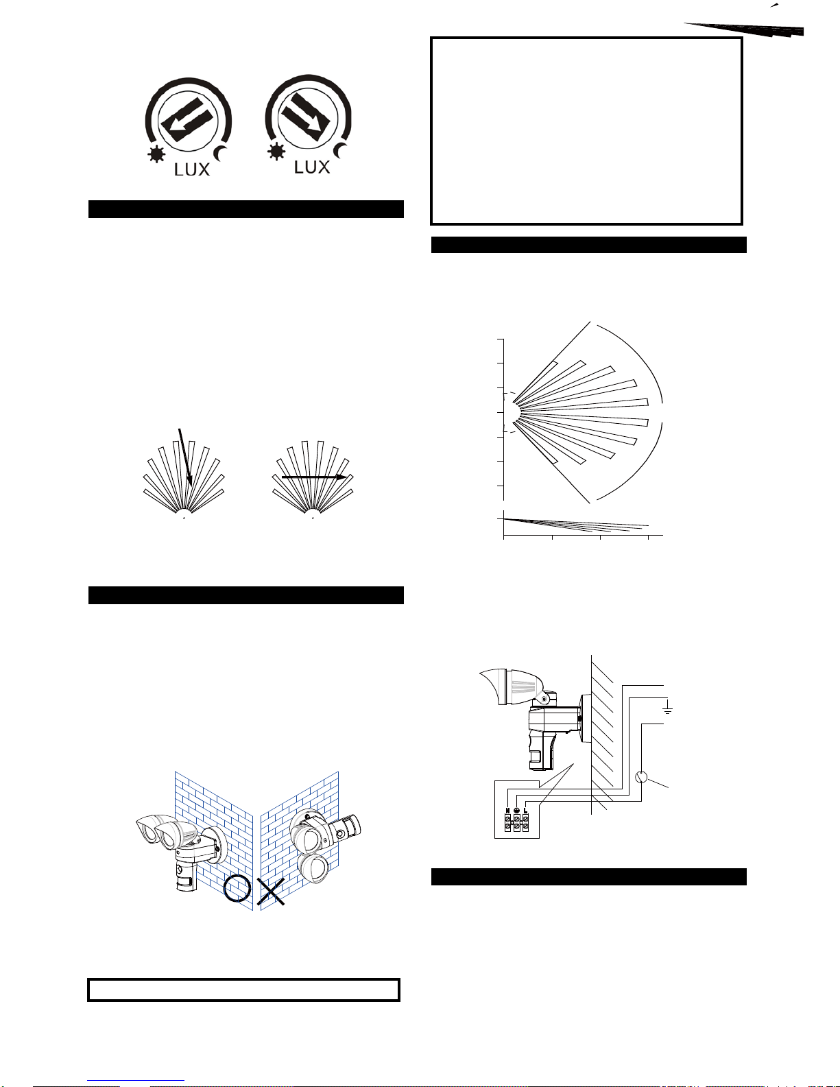
T o start turn the LUX control knob to the edge with the
moon (dusk) position (FIGURE 31). In this provisional
setting mode, the Motion Sensor remains inactive
during daylight. At dusk when you have found the LUX
level desired for operation, simply set the LUX control
knob to the position desired (which will allow the sensor
to become active as daylight declines)
Sensitivity 4
(Lowest Sensitivity)
Sensitivity 1
(Highest Sensitivity)
Sensitivity 2
Sensitivity 3
Page 7
7
Note: The LUX setting range is between 20 LUX to 200
LUX.
FIGURE 31
CHOOSING A MOUNTING LOCATION
For best results affix the unit on a solid surface, 2 -
2.5m (6.5 – 8 feet) above the ground
Avoid aiming the unit at pools, heating vents, air
conditioners, or other objects which change in
temperature rapidly
Sunlight falling directly on the front of the unit may
affect video quality. It is recommended to test the
location prior to installation.
Try to avoid pointing the unit at trees, shrubs or
where the motion of pets may often be detected
The motion sensor is more sensitive to objects
moving across its field of view. It is less sensitive
to an object moving directly towards the sensor
head. (FIGURE 32).
MORE SENSITIVE
SENSOR
LESS SENSITIVE
SENSOR
FIGURE 32
SAFETY PRECAUTIONS
Do not install the Motion Activated Dual Light &
Video Camera when it is raining
Be sure to switch off power source before
installing
To avoid fire or burning hazards; allow fixture to
cool before touching. The bulb and the fixture
operate at high temperatures
When mounting on the wall, the unit must be
installed vertically (FIGURE 33a), not horizontally
(FIGURE 33b).
VERTICAL HORIZONTAL
FIGURE 33a & 33b
IM PO RTANT
Installation must be performed by skilled technicians
who are aware about the standards and technical
requirements of the appliance and its proper
installation.
Check your local codes as they apply to your
situation. If the house wiring is aluminum, consult
with an electrician about proper wiring methods.
Before proceeding with the installation, TURN OFF
THE POWER TO THE LIGHTING CIRCUIT AT THE
CIRCUIT BREAKER OR FUSE BOX TO AVOID
ELECTRICAL SHOCK.
INSTALLATION
A drill and a screwdriver are needed for installation.
Select a location for the unit based on the coverage
angles as shown in FIGURE 34.
TOPVIEW
0
12
2
4
8
4
0
12
8
84
SIDEVIEW
12
UNIT:m
1
1
0
°
FIGURE 34
Install a wall switch adjacent to the power source.
(FIGURE 35). This will help you operate the unit with
ease.
N
L
WALL
SWITCH
AC
POWER
FIGURE 35
WIRING INSTRUCTIONS
American Version
(1) Switch off the power source or wall switch
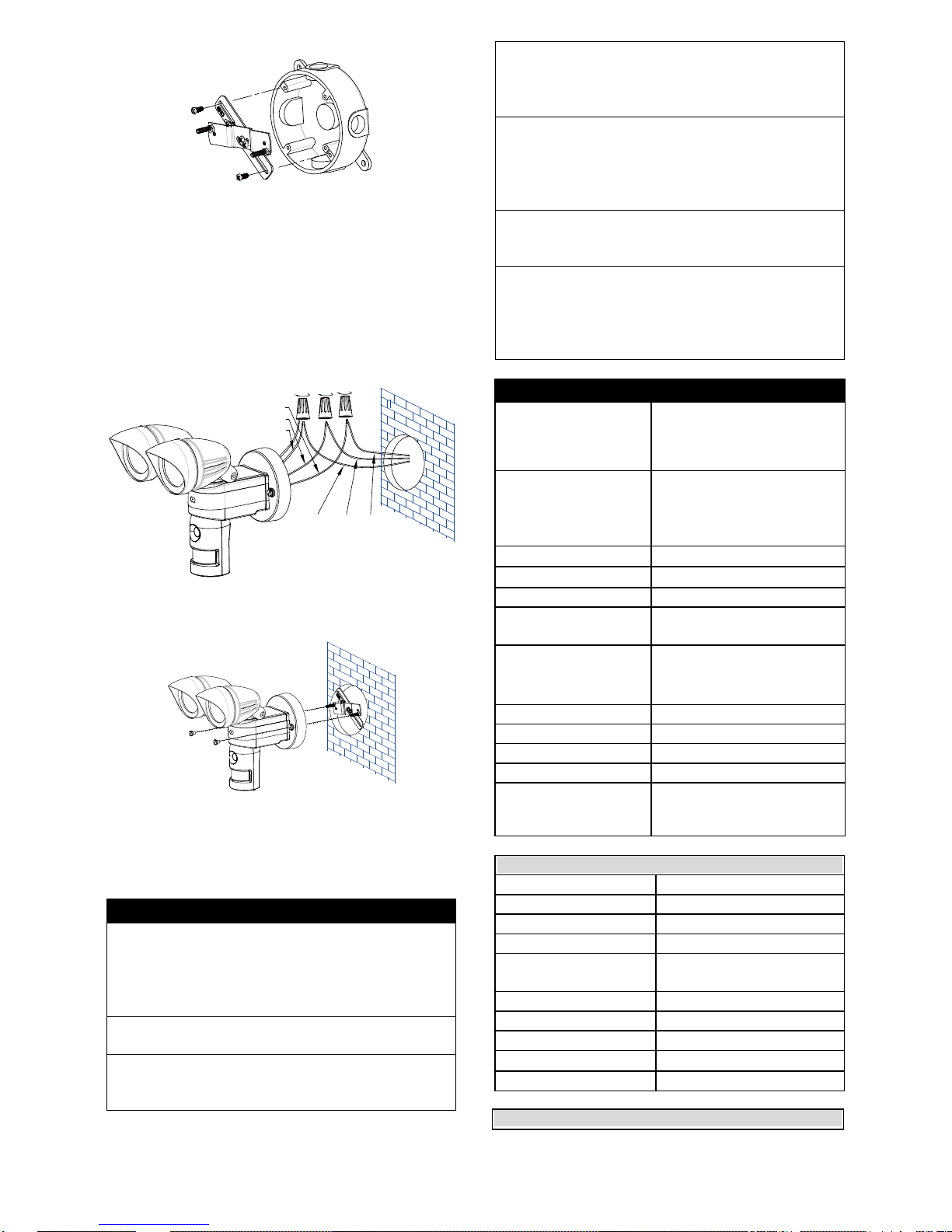
(2) Line up the holes on the mounting bracket with the
holes on your junction box. Using fitting screws
(depending on size of the holes in your junction
box), and attach the mounting bracket to your
junction box (FIGURE 36).
Page 8
8
FIGURE 36
(3) Place the gasket in position before wiring
(4) Connect the brown wire from the fixture to the
brown (Live) power supply wire from your power
source using the wire nuts provided. Connect the
blue wire from the fixture to the blue (Neutral)
power supply wire using the wire nuts provided.
Connect the yellow/green wire from the fixture to
the yellow/green (Earth) power supply wire using
the wire nuts provided (FIGURE 37).
Earth Neutral
Live
Brown
Blue
Yellow/Green
FIGURE 37
(5) Place the wiring box and secure it with the two
screws provided. (FIGURE 38)
FIGURE 38
Note: THIS EQUIPMENT MUST NOT BE MOUNTED
ON AN OUTLET BOX WHICH IS SUPPORTED BY A
BAR HANGER (or equivalent)
TROUBLESHOOTING
Light does not turn on:
Confirm that you have made a correct “wiring
connection”
Make sure that the bulb has not burned out
and is installed correctly
Warning Sound is on after powering up:
SD card is not inserted
PIR and LUX settings are not working:
Do not allow sunlight to fall directly on to the
front of the unit
Warning sound and video recording is not on:
They are on only when the unit is triggered
Make sure the unit is not on Scene 4
Please re-power the unit
Filmed videos can’t be saved onto the SD card:
Damage of the videos might be caused by
inappropriate retrieval/insertion of SD card;
ensure the unit is powered off before action is
taken
Video and sound recording is not functioning:
The function is disabled if the unit is set to
scene 4
Views of people are blurred during the night:
Avoid the s k y a s a background; turn the
camera lens down if needed
Try not to spot the light on reflective objects;
the reflection of light could cause blurriness
SPECIFICATIONS
Power Requirement
120V~ 60Hz for USA or
220-240V~ 50Hz for EU or
1.5V AA alkaline battery x 4
(for SD card & camera only)
Lighting Load
Max. 60W x 2 G9 Halogen
Bulb (VC613-1)
Max. 60W x 1 G9 Halogen
Bulb (VC613-4)
PIR Detection Angle
Up to 150°
PIR Detection Distance
Up to 12m under 28°C
Protection Class
I
Protection Degree
IP44 for Europe. Suitable for
wet locations for USA
Swiveling Angle
Sensor Part: Horizontal 90°
(45° left, right), Vertical 30°
(downward)
Mounting Height
2 to 2.5m
Tim e Adjustment
20 secs/1 min /5 mins
Lux Adjustment
Y e s
Warm U p T i m e
About 60 second
Operating Temperature
Range
-10°C ~ 40°C. 20~85%
relative humidity,
non-condensation.
CAMERA
Pixel
640 x 480 Pixel VGA
Lux Sensitivity
1 Lux
White Balance
Auto
AGC
Auto
Backlight
Compensation
Auto
SNR
>48 dB
Gamma Compensation
0.45
Electric Shutter
Auto
Angle
60°
Microphone
Built-in
SD Card
Page 9
9
Write-protect Switch
YES
Capacity
Min. 512MB ~ Max. 32GB
(2GB SD card is included)
Format
F A T / F A T 3 2
*Specifications are subject to change without prior notice.
A501111614R03
Federal Communication Commission Interference
Statement
This equipment has been tested and found to comply with the
limits for a Class B digital device, pursuant to Part 15 of the
FCC Rules. These limits are designed to provide
reasonable protection against harmful interference in a
residential installation. This equipment generates, uses and
can radiate radio frequency energy and, if not installed and
used in accordance with the instructions, may cause harmful
interference to radio communications. However, there is no
guarantee that interference will not occur in a particular
installation. If this equipment does cause harmful
interference to radio or television reception, which can be
determined by turning the equipment off and on, the user is
encouraged to try to correct the interference by one of the
following measures:
- Reorient or relocate the receiving antenna.
- Increase the separation between the equipment and
receiver.
- Connect the equipment into an outlet on a circuit different
from that to which the receiver is connected.
- Consult the dealer or an experienced radio/TV technician for
help.
This device complies with part 15 of the FCC rules.
Operation is subject to the following two conditions.
1) This device may not cause harmful interference, and
2) This device must accept any interference received,
including interference that may cause undesired
operation.
Per FCC 15.21, you are cautioned that changes or
modifications not expressly approved by the part responsible
for compliance could void the user’s authority to operate the
equipment.
IMPORTANT NOTE:
FCC Radiation Exposure Statement:
This equipment complies with FCC radiation exposure limits
set forth for an uncontrolled environment. End users must
follow the specific operating instructions for satisfying RF
exposure compliance.
This transmitter must not be co-located or operating in
conjunction with any other antenna or transmitter.
Do not dispose of electrical appliances as unsorted municipal
waste, use separate collection facilities.
Contact your local government for information regarding the
collection systems available.
If electrical appliances are disposed of in landfills or dumps,
hazardous substances can leak into the groundwater and get
into the food chain, damaging your health and well-being.
When replacing old appliances with new once, the retailer is
legally obligated to take back your old appliance for disposal
at least for free of charge.
Q & A
1. Is a software CD needed to view video from a
computer? No – the SD card will store the video
recordings and can be inserted directly into your
computer for viewing/saving videos
2. Does the camera record video and still images? No –
this is a video recording unit only
 Loading...