

Page 1
FEATURES
4 Boom Positions with Rated Capacity Indicated
MODEL #5218
4000 LB. CAPACITY
BREAKDOWN ENGINE CRANE
LOW CLEARANCE WITH 8 TON QUICK LIFT RAM
PARTS BREAKDOWN AND OPERATING MANUAL
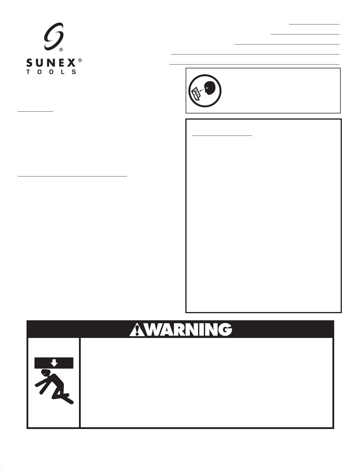
THIS OPERATING MANUAL CONTAINS
IMPORTANT SAFETY INFORMATION.
READ CAREFULLY AND UNDERSTAND
ALL INFORMATION BEFORE OPERATING
TOOL. SAVE THIS MANUAL FOR FUTURE
USE.
Heavy Duty Slow Release Power Unit
4" Front Leg Clearance
8 Ton Quick Lift Ram
OWNER/USER RESPONSIBILITY:
The owner and/or user must have a thorough understanding
of the manufacturer’s operating instructions and warnings
before using this mobile crane. Personnel involved in the
use and operation of equipment shall be careful, competent,
trained, and qualified in the safe operation of the equipment
and its proper use when servicing motor vehicles and their
components. Warning information should be emphasized
and understood. If the operator is not fluent in English, the
manufacturer’s instructions and warnings shall be read to and
discussed with the operator in the operator’s native language
by the purchaser/owner, making sure that the operator comprehends its contents.
Owner and/or user must study and maintain for future
reference the manufacturer’s instructions. Owner and/or user
is responsible for keeping all warning labels and instruction
manuals legible and intact. Replacement labels and literature
are available from the manufacturer.
SPECIFICATIONS:
Pos. 1 Pos. 2 Pos. 3 Pos. 4
Max. Boom Ht. ..........95.25" ........91.25" ........ 87" ............82.5"
Min. Boom Ht. ............... 0" ............. 5.75" .......12.25" ......... 18.5"
Boom Capacity ..........1/2 Ton .........1 Ton ..... 1-1/2 Ton .......2 Ton
Boom Ext. From End
to Ram ..................... 50" ............42.5" ........ 35.5" ..........28.5"
Base Dimensions – Open
Width Back ................................................................... 34"
Width Front .............................................................. 35.5"
Length ....................................................................... 69.5"
Base Dimensions – Folded
Width Back ................................................................... 34"
Width Front ................................................................. 24"
Depth ......................................................................... 21.5"
Power Unit .......................... 8 Ton Heavy Duty Quick Lift
Shipping Weight ...................................................210 Lbs.
(Shipped in 2 boxes)
THIS CRANE IS DESIGNED FOR ENGINE LIFTING PURPOSES ONLY.
WHEN REMOVING ENGINES FROM VEHICLES, BE SURE THAT THE
FRONT OF THE VE HICLE IS NOT JAMMED AGAINS T THE
HYDRAULIC UNIT. FAILURE TO OBSERVE THIS WARNING COULD
RESULT IN A DROPPED ENGINE.
A VISUAL INSPECTION SHOULD BE MADE BEFORE EACH USE OF
THE CRANE, CHECKING FOR LEAKING HYDRAULIC FLUID AND
CRACKED, DAMAGED, LOOSE OR MISSING PARTS.
DO NOT OVERLOAD. OVERLOADING CAN CAUSE DAMAGE TO OR
FAILURE OF THE MOBILE CRANE.
LOWER BOOM AND LOAD TO THE LOWEST POSSIBLE POSITION
BEFORE TRANSPORTING.
ASSURE THAT THE LOAD IS NOT ALLOWED TO DROP SUDDENLY
OR SWING DURING TRANSPORTING.
5218 1 rev. 12/31/04
MAKE SURE THAT BOOM IS FULLY LOWERED BEFORE ADDING OIL
TO UNIT RESERVOIR.
THIS MOBILE CRANE IS DESIGNED FOR USE ONLY ON HARD LEVEL
SURFACES CAPABLE OF SUSTAINING THE LOAD. USE ON OTHER
THAN HARD LEVEL SURFACES CAN RESULT IN MOBILE CRANE
INSTABILITY AND POSSIBLE LOSS OF LOAD.
NO ALTERATIONS TO THE MOBILE CRANE SHALL BE MADE. USE
ONLY SLINGS OR CHAINS WITH CAPACITY GREATER THAN THAT
OF THE LOAD BEING LIFTED.
READ, STUDY AND UNDERSTAND THE INSTRUCTION MANUAL
PACKED WITH THIS CRANE BEFORE USING CRANE.
FAILURE TO HEED THESE WARNINGS MAY RESULT IN LOSS OF
, DAMAGE TO CRANE, AND/OR FAILURE RESULTING IN
LOAD
PROPERTY DAMAGE, PERSONAL OR FATAL INJURY.
Page 2

ASSEMBLY INSTRUCTIONS
NOTE: An assistant is required to assemble this unit and
minimize the potential hazards and/or injury.
1. Line up the holes on the Caster Wheels (29) with the
matching holes on the Base (7) and attach with Bolts
(32).
2. Slide the right Front Leg Extension (wheel angled
slightly inward) (1) into right side of Base (7) until the
pin hole aligns with the pin hole on base. Slide Pin (3)
through hole in leg extension and base and secure pin
with Clip (8). Repeat this procedure for the left front
leg extension.
3. With the help of an assistant, install the Upright Mast
(10) onto the base using Bolts (6), Washers (5) and Nuts
(4). Install the Mast Braces (9) onto the base using Bolts
(6), Washers (5) and Nuts (4). Align holes at the upper
end of the Mast Braces with the second hole from the
top in the Upright Mast using Bolt (14), Washer (15)
and Nut (16). Once aligned, tighten the bolts securely.
4. Install the Hydraulic Ram (13) to the support bracket
on the Upright Mast using Bolt (11), Washer (15) and
Nut (16). Once secured, lean the hydraulic ram against
the Upright Mast temporarily.
5. Install the Boom (25) on top of the Upright Mast and
secure with Bolt (20), Washer (21) and Nut (22).
6. Align and install the top of the hydraulic ram into the
welded fork on the boom and secure with Bolt (23),
Washer (15) and Nut (16).
7. Slide Boom Extension (26) into boom and secure with
Slide Pin (24) and secure with Clip (8).
8. Install the Hook and Chain (27) at the end of the boom
extension using Bolt (28), Washer (5) and Nut (4).
OPERATING INSTRUCTIONS
1. Lock the boom in place for the proper weight marking
using the lock pin BEFORE APPLYING THE LOAD TO THE
LIFT. Do not exceed the rated capacity and travel limits
of the equipment.
2. Use appropriate levellers, slings or chains around the
load capable of sustaining the load before using the
hook to lift it. Make sure that the latching mechanism
is working properly before lifting or moving the load.
3. Once the load is securely hooked in place, lift the load
by turning the release valve clockwise until closed,
and pumping the jack until the load is clear of any
obstruction. Move very carefully avoiding slopes in
the direction of travel. Avoid sudden or swinging
movements of the load. To lower the load, turn the
release valve on the hydraulic jack counterclockwise
very slowly.
TROUBLE SHOOTING
SYSTEM AIR PURGE
1. Turn release valve counterclockwise one full turn
to open.
2. Pump handle eight full strokes.
3. Turn release valve clockwise to closed position.
4. Pump handle until the lift arm reaches maximum
height and continue to pump several times to remove
trapped air in the ram.
5. Turn release valve counterclockwise one full turn to
open and allow lift arm to retract.
6. Close release valve and check for proper pump action.
It may be necessary to perform the above move more
than once to assure air is evacuated totally.
9. Slide the Handle (12) on the socket on the hydraulic
ram.
5218 2 rev. 12/31/04
OTHER SYMPTOMS
Jack will not lift to full height: Low oil level
Jack will not hold: Release valve not closing
Dirt in hydraulic jack
oil or pump valves not
sealing
Refer to Air Purge
Section
Lift arm will not lower: Cylinder ram binding
Release valve broken
Parts worn
Jack feels spongy when lifting: See Air Purge section
Page 3

MODEL # 5218
4000 Lb. Capacity
Low Clearance
Breakdown Engine Crane
Item # Part # Description Qty. Item # Part # Description Qty
1 RS521801 Right Leg Extension 1 17 Bolt 4
2 RS521802 Left Leg Extension 1 18 Spring Washer 4
3 Dowel Pin 2 19 RS521819 Push Bar 1
4 Nut 5 20 Bolt 1
5 Washer 5 21 Washer 1
6 Bolt 4 22 Nut 1
7 RS521807 Base 1 23 Bolt 1
8 Cotter Pin 3 24 Dowel Pin 1
9 RS521809 Mast Brace 2 25 RS521825 Boom 1
10 RS521810 Upright Mast 1 26 RS521826 Boom Extension 1
11 Bolt 1 27 RS521827 Hook & Chain 1
12 RS521812 Handle 1 28 Bolt 1
13 RS80QL Hydraulic Ram (incl. #12) 1 29 RS521829 Rear Caster 2
14 Bolt 1 30 RS521830 Front Base Wheel 2
15 Washer 3 31 RS521831 Front Leg Wheel 2
16 Nut 3 32 Bolt - M8 x 16 8
RS5218BK Hardware Kit (including # 3, 4, 5, 6, 8, 11, 14, 15, 16, 17, 18, 20, 21, 22, 23, 24, 27, 28, 32)
Only items identified by part number are available for purchase.
5218 3 rev. 12/31/04
Page 4

MAINTENANCE AND INSPECTION
1. Inspect the crane before each use. Check for cracks in the
jack support, boom and boom extension. Check for loose,
missing or damaged parts and for hydraulic oil leaks. If the
crane is damaged in any way, it should be removed from
service immediately.
2. Check for unauthorized modification of the product.
Modifications to this product and/or use of unapproved
attachments are prohibited due to the potential hazards
that are associated with improper use.
3. Any crane which appears to be damaged in any way,
found to be worn, or operates abnormally MUST BE
REMOVED FROM SERVICE UNTIL REPAIRED. Owners
and/or operators should be aware that repair of the equipment requires specialized knowledge and facilities. Only
factory authorized parts, labels and decals shall be used on
this equipment.
4. If jack is subjected to abnormal load or shock, remove
from service and have it examined by an Authorized
Repair Service.
5. Clean all surfaces and maintain all labels and warnings.
6. Grease Pivot Points:
A. Boom to Upright Support Post
B. Ram Mount to Boom
A list of authorized repair facilities is available from the
manufacturer.
CHECK OIL LEVEL
WARNING
Always purchase those products labeled “Hydraulic Jack Oil”.
Do not use brake or transmission fluids, as they can damage
the seals.
1. Turn release valve counterclockwise to allow ram to
fully retract.
2. Remove fill plug.
3. With jack in vertical position, proper oil level should be
even with bottom of hole. If low, fill with NEW, clean
hydraulic jack oil and recheck level. Do not overfill!!
4. Replace filler plug.
5. Turn release valve counterclockwise one full turn to open
and allow lift arm to retract.
6. Close release valve and check for proper pump action. It
may be necessary to perform the above move more than
once to assure air is evacuated totally.
STORAGE
1. Lower the boom (25) to its lowest position, with the boom
extension (26) slid into position #4. Ensure pin (24) is
installed and secured with clip (8).
2. Remove clips and pins (3, 8) holding front legs (1, 2) to the
base (7). Remove front legs from base and position them
vertically in the storage pockets located slightly to the rear
of the wheels (30) on base.
3. Reinstall the clips and pins removed in step 2 to prevent
the loss of parts.
LIMITED WARRANTY:
SUNEX INTERNATIONAL, INC. WARRANTS TO ITS CUSTOMERS THAT THE COMPANY’S SUNEX TOOLS
ARE FREE FROM DEFECTS IN WORKMANSHIP AND MATERIALS.
Sunex International, Inc. will repair or replace its Sunex Tools
defective workmanship or materials, based upon the terms and conditions of the following described warranty plans attributed
to that specific product.
This product carries a ONE-YEAR warranty. During this warranty period, Sunex Tools will repair or replace at our option any part
or unit which proves to be defective in material or workmanship.
Other important warranty information...
This warranty does not cover damage to equipment or tools arising from alteration, abuse, misuse, damage and does not cover
any repairs or replacement made by anyone other than Sunex Tools or its authorized warranty service centers.
The foregoing obligation is Sunex Tools’ sole liability under this or any implied warranty and under no circumstances shall we
be liable for any incidental or consequential damages.
Note: Some states do not allow the exclusion or limitation of incidental or consequential damages, so the above limitation or
exclusion may not apply to you.
Return equipment or parts to Sunex Tools, transportation prepaid. Be certain to include your name and address, evidence of the
purchase date, and description of the suspected defect.
If you have any questions about warranty service, please write to Sunex Tools. This warranty gives you specific legal rights and
you may also have other rights which vary from state to state.
Repair kits and replacement parts are available for many of Sunex Tools products regardless of whether or not the product is
still covered by a warranty plan.
SHIPPING ADDRESS:
Sunex Tools
315 Hawkins Rd.
Travelers Rest, South Carolina 29690
®
branded products which fail to give satisfactory service due to
MAILING ADDRESS:
Sunex Tools
P.O. Box 4215
Greenville, South Carolina 29608
®
BRANDED PRODUCTS
5218 4 rev. 12/31/04
 Loading...